

Motorola MC13159DTB Datasheet
Device
Operating
Temperature Range
Package
SEMICONDUCTOR
TECHNICAL DATA
WIDEBAND FM IF
SUBSYSTEM FOR PHS
AND DIGITAL
APPLICATIONS
ORDERING INFORMATION
TA = –30° to +85°C TSSOP–16
DTB SUFFIX
PLASTIC PACKAGE
CASE 948F
(TSSOP–16)
16
1
Order this document by MC13159/D
MC13159DTB
1
MOTOROLA ANALOG IC DEVICE DATA
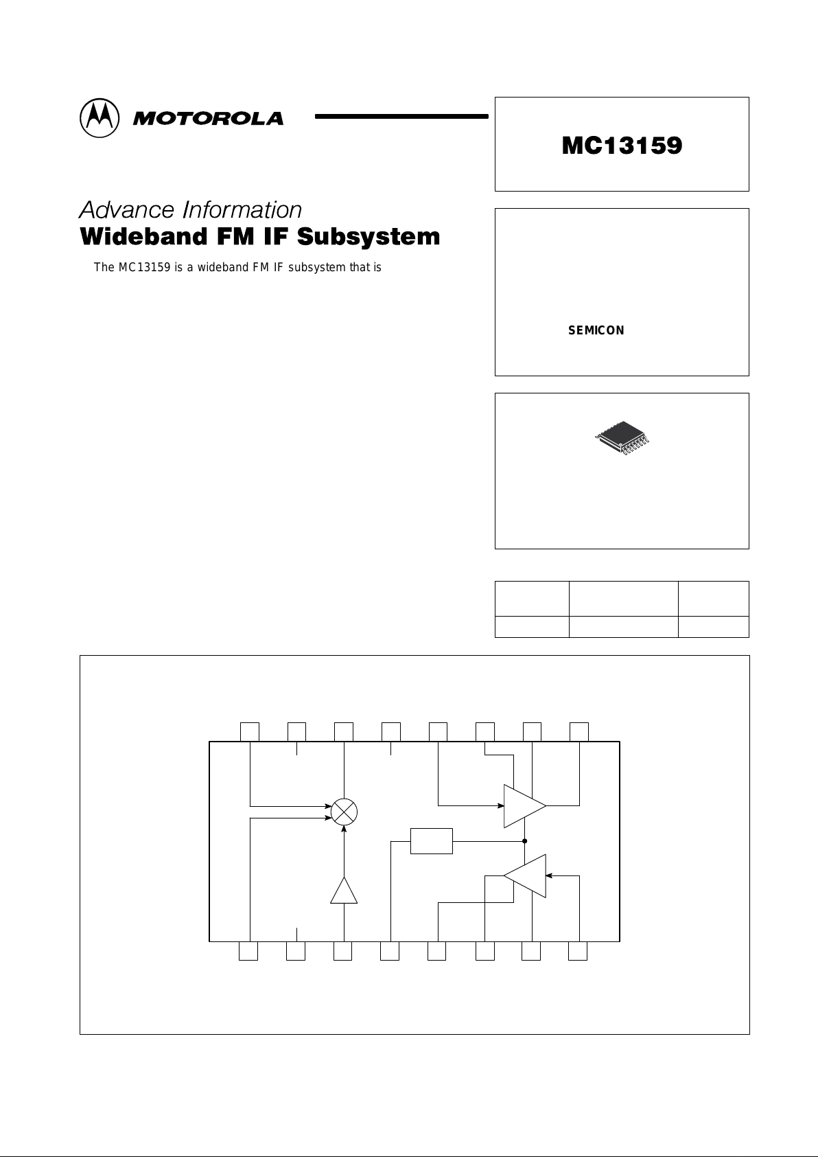
The MC13159 is a wideband FM IF subsystem that is designed for high
performance data and digital applications. Excellent high frequency
performance is achieved, with low cost, through the use of Motorola’s RF
bipolar process. The MC13159 includes a mixer, local oscillator buffer
amplifier, IF amplifier, limiter amplifier and RSSI functions. The mixer is
useful for a 240 MHz input used in a single–ended/balanced differential
configuration. The IF and limiter amplifier are separated so that an external
filter can be used in series, or connected directly with an external capacitor.
The RSSI output is derived by summing the output of both the IF and
Limiter sections. An enable control is provided to power down the IC for
power management in battery powered applications.
Suitable applications include PHS, DECT, PDC, and PCS telephones,
wideband wireless data links, and other battery powered radio systems.
• Designed for PHS Applications
• 2.7 to 5.5 V Operating Voltage
• Low Drain Current: 5.5 mA (Typ)
• Wide Input Dynamic Range of Mixer (Maximum –16 dBm Input)
• Enable Function for Power Down Mode
• Over 80 dB of RSSI Dynamic Range (AC Coupling between IF Amplifier
and Limiter Amplifier)
• Few External Components Required
Simplified Block Diagram
16 15 14 13 12 11 10 9
Mix
in
V
EE
Mix
out
Enable
IF
in
IF
Dec1IFDec2
IF
out
Mix
Decoup
V
CC
LO
in
RSSI
Mixer
IF Amp
LIM
Amp
RSSI
12345678
LIM
out
LIM
Dec2
LIM
Dec1
LIM
in
Local
Oscillator
Buffer
This device contains 164 active transistors.
This document contains information on a new product. Specifications and information herein
are subject to change without notice.
Motorola, Inc. 1997 Rev 1
MC13159
2
MOTOROLA ANALOG IC DEVICE DATA
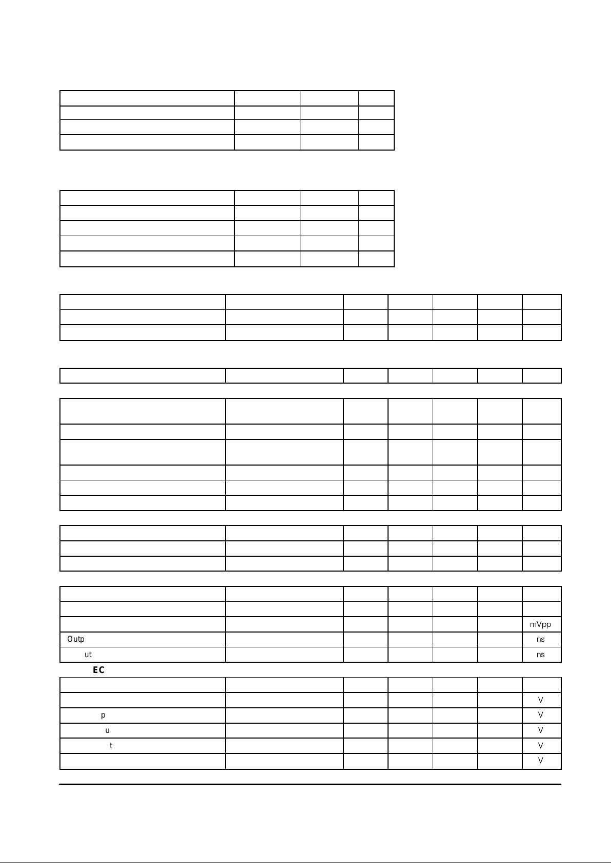
MAXIMUM RATINGS
Rating Symbol Value Unit
Power Supply Voltage V
S(max)
6.0 Vdc
Junction Temperature T
Jmax
150 °C
Storage Temperature Range T
stg
–65 to +150 °C
NOTE: ESD data available upon request.
RECOMMENDED OPERATING CONDITIONS
Rating Symbol Value Unit
Power Supply Voltage V
S
2.7 to 5.5 Vdc
Input Frequency f
in
10 to 600 MHz
Ambient Temperature Range T
A
–30 to +85 °C
Input Signal Level at Local Input V
in
–10 dBm
DC ELECTRICAL CHARACTERISTICS (T
A
= 25°C, VS = 3.0 V; No Input Signal)
Characteristics Conditions Symbol Min Typ Max Unit
Total Drain Current 1 Active Mode I
CC1
4.5 5.5 7.5 mA
Total Drain Current 2 Disable Mode I
CC2
– 0.1 10 µA
AC ELECTRICAL CHARACTERISTICS
Characteristics Conditions Symbol Min Typ Max Unit
MIXER (T
A
= 25°C; VS = 3.0; fRF = 240 MHz, fLO = 229.3 MHz)
Mixer Conversion Gain 50 Ω Termination
Input Matched
– 11
–
14
21
17
–
dB
Noise Figure Input Matched NF – 14 – dB
Mixer Input Impedance Single–Ended Rp
Cp
–
–
400
4.0
–
–
Ω
pF
Mixer Output Impendance – – – 330 – Ω
1.0 dB Gain Compression @Mix
in
Vicp – –16 – dBm
3rd Order Input Intercept 50 Ω Termination IIP3 – –8.0 – dBm
IF AMPLIFIER SECTION (T
A
= 25°C; VS = 3.0 V; fIF = 10.7 MHz)
IF Gain f = 10.7 MHz – 32 36 45 dB
Input Impedance – – – 330 – Ω
Output Impedance – – – 330 – Ω
LIMITING AMPLIFIER SECTION (T
A
= 25°C; VS = 3.0 V; fIF = 10.7 MHz)
Limiter Gain f = 10.7 MHz – – 70 – dB
Input Impedance – – – 330 – Ω
Output Swing – – 400 500 600
mVpp
Output Rise Time – – – 10 –
ns
Output Fall Time – – – 20 –
ns
RSSI SECTION (T
A
= 25°C; VS = 3.0 V; fIF = 10.7 MHz)
RSSI Slope – – 10 14 18 mV/dB
RSSI Output DC Voltage 1 No Input Signal – 0.8 0.9 1.0
V
RSSI Output DC Voltage 2 VIF = –85 dBm – 0.82 0.95 1.02
V
RSSI Output DC Voltage 3 VIF = –80 dBm – 0.85 1.0 1.15
V
RSSI Output DC Voltage 4 VIF = –40 dBm – 1.4 1.5 1.6
V
RSSI Output DC Voltage 5 Vin = 0 dBm – 1.95 2.1 2.25
V
MC13159
3
MOTOROLA ANALOG IC DEVICE DATA
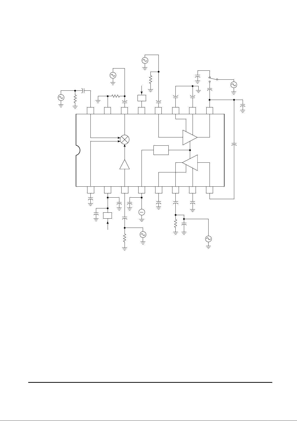
Figure 1. Test Circuit
Mix
out
10.7 MHz
RF
in
240 MHz
10 n
Mix
in
V
EE
16 15 14 13 12 11 10 9
1.0 n
Enable
IF
in
IF
Dec1
IF
out
IF
Dec2
Mix
out
Mix
Decoup
LO
in
1234
RSSI
LIM
876
5
50
220 p
100 n
1.0 n
47 p
10 n
10 n 10 n
10 p
(From Probe
Impedance)
10 k
DCI
39 p
50
Mixer
LIM
in
LIM
Dec1
LIM
out
LIM
Dec2
RSSI
IF
V
CC
V
CC
Local Osc Input
229.3 MHz
–10 dBm
1.0 n
10 n
330
50
10 n
1.0 n
10 n
IF
in
10.7 MHz
IF
out
10.7 MHz
a
b
39 p
DCI
V
V
V
V
S1
Local
Oscillator
Buffer
 Loading...