

Motorola MC13001XP, MC13007XP Datasheet
Device
Operating
Temperature Range
Package
SEMICONDUCTOR
TECHNICAL DATA
MONOMAX
BLACK AND WHITE TV
SUBSYSTEM
ORDERING INFORMATION
MC13001XP
MC13007XP
TA = 0° to +70°C Plastic DIP
Order this document by MC13001X/D
P SUFFIX
PLASTIC PACKAGE
CASE 710
1
MOTOROLA ANALOG IC DEVICE DATA
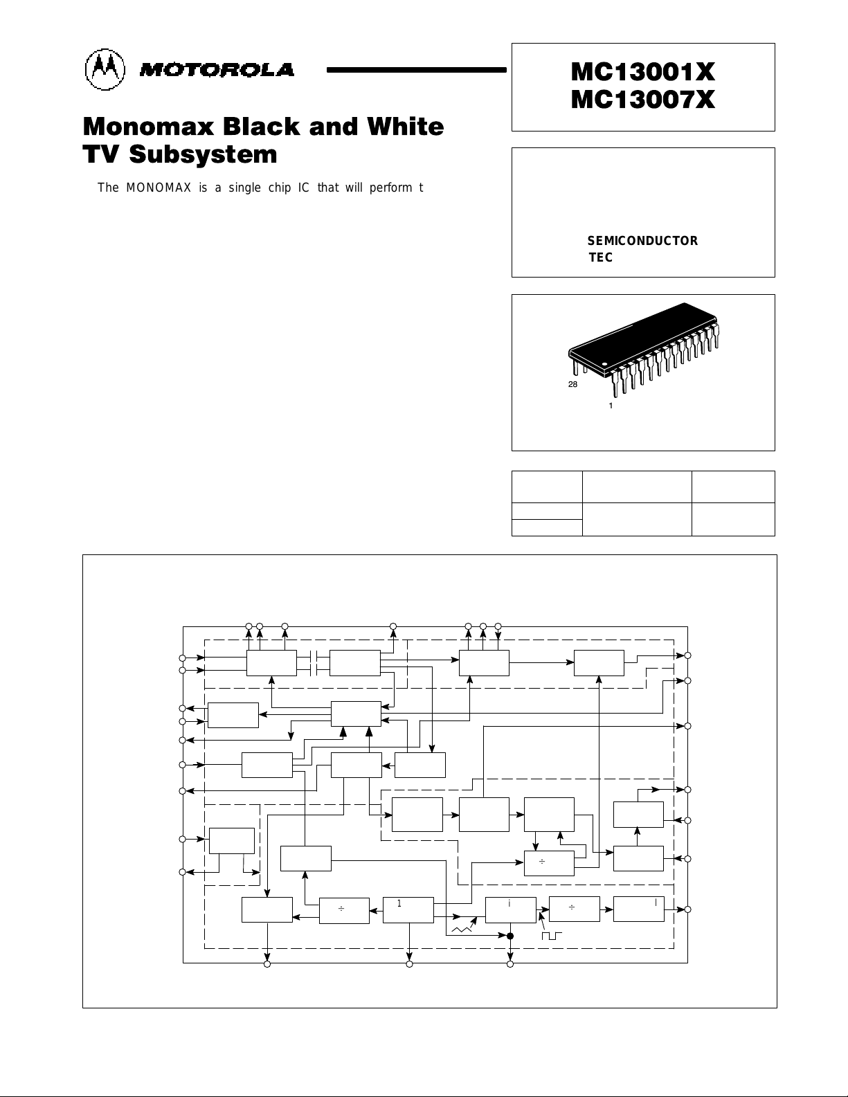
The MONOMAX is a single chip IC that will perform the electronic
functions of a monochrome TV receiver, with the exception of the tuner,
sound channel, and power output stages. The MC13001XP and
MC13007XP will function as a drop–in replacement for the MC13001P and
MC13007P, but some external IF components can be removed for maximum
benefit. IF AGC range has been increased, video output impedance lowered,
and horizontal driver output current capability increased.
• Full Performance Monochrome Receiver with Noise and Video
Processing (Black Level Clamp, DC Contrast, Beam Limiter)
• Video IF Detection On–Chip (No Coils, No Pins, except Inputs)
• Noise Filtering On–Chip (Minimum Pins and Externals)
• Oscillator Components On–Chip (No Precision Capacitors Required)
• MC13001XP for 525 Line NTSC and MC13007XP for 625 Line CCIR
• Low Dissipation in All Circuit Sections
• High Performance Vertical Countdown
• 2–Loop Horizontal System with Low Power Startup Mode
• Noise Protected Sync and Gated AGC System
• Designed to work with TDA1190P or TDA3190P Sound IF and Audio
Output Devices
Figure 1. Basic Elements of the System
Vertical
Integrator
Vertical
Sync
Separator
Window
Control
& Reset
IF In
IF In
RF AGC
RF AGC Delay
AGC
Flyback
Horizontal Sync
Separator
V
CC
3
5
11
10
9
15
7
18
19+8.0V Out
4 2 6 26 25 27
VIF IF Decoupling
Sound
IF
28
Contrast Beam Limit
24
8
23
22
21
20
17
Video Out
AGC Filter
Vertical Sync
Vertical Out
Vertical
Feedback
Vertical Size
Horizontal Out
13 12 14
Horizontal Phase
Detector 1
Horizontal Frequency
Video IF
VIF Detector
Video
Process
Blank
Buffer
Video Process
AGC Sync
RF
AGC
AGC
AGC
Feed Forward
Sync
Separator
Noise
Process
Vertical
Clock
B
525
Vertical
Ramp
Horizontal
Phase
Detector 2
Regulator
B
2
31.5 kHz
Oscillator
B
2
Vertical
Preamp
Phase
Detector 1
Variable
Slicer
Horizontal
Buffer
Flyback
Buffer
Black
Clamp
Horizontal Phase
Detector 2
Motorola, Inc. 1995
MC13001X MC13007X
2
MOTOROLA ANALOG IC DEVICE DATA
MAXIMUM RATINGS
(TA = 25°C, unless otherwise noted.)
Rating
Symbol Value Unit
Power Supply Voltage – Pin 18 V
CC
+16 Vdc
Power Dissipation P
D
1.0 W
Horizontal Driver Current – Pin 17 I
hor
–20 mA
RF AGC Current – Pin 11 I
RFAGC
20 mA
Video Detector Current – Pin 24 I
VID
5.0 mA
Vertical Driver Current – Pin 22 I
vert
5.0 mA
Auxiliary Regulator Current – Pin 19 I
reg
35 mA
Thermal Resistance Junction–to–Case Rθ
JC
60 °C/W
Maximum Junction Temperature T
J
150 °C
Storage Temperature Range T
stg
–65 to + 150 °C
Operating Temperature Range T
A
0° to + 70 °C
RECOMMENDED OPERATING CONDITIONS
Rating Symbol Value Unit
Horizontal Output Drive Current I
hor
≤10 mA
RF AGC Current I
RFAGC
≤10 mA
Regulator Current I
reg
≤20 mA
ELECTRICAL CHARACTERISTICS (V
CC
= 11.3 V, TA = 25°C)
Characteristics
Symbol Min Typ Max Unit
Power Supply Current (Pins 18, 19) I
CC
44 – 76 mA
Regulator Voltage (Pin 19) V
reg
7.2 8.2 8.8 Vdc
HORIZONTAL SPECIFICATIONS
Oscillator Frequency (Nominal) (Pin 12) f
hor(NOM)
13 – 19 kHz
Oscillator Sensitivity – 230 – Hz/µA
Startup Frequency (I18 = 4.0 mA) f
hor
–10 – +10 %
Oscillator Temperature Stability (0 ≤ TA ≤ 75°C) – – 50 – Hz
Phase Detector 1 (Charge/Discharge Current)
(Non–Standard Frame)
(Standard Frame)
Iφ
1
–
–
±900
±400
–
–
µA
Phase Detector 2
(Charge/Discharge Current)
Vφ
2
– +1.0
–0.6
– mA
Phase Detector 1
(Output Voltage Limits)
Vφ
1
– 7.5 (max)
2.5 (min)
– Vdc
Phase Detector 2
(Output Voltage Limits)
Vφ
1
– 7.7 (max)
1.5 (min)
–
Phase Detector 1
(Leakage Current)
– – 2.0 µA
Phase Detector 2
(Leakage Current)
– – 3.0
Horizontal Delay Range
(Sync to Flyback)
–
–
18 (max)
5.0 (min)
–
–
µs
Horizontal Output Saturation Voltage
(I17 = 15 mA)
V
17(sat)
– – 0.3 Vdc
Phase–Detector 1 (Gain Constant)
(Out–of–Lock)
(In–Lock)
–
–
5.0
10
–
–
µA/µs
Horizontal Pull–In Range ±500 ±750 – Hz
MC13001X MC13007X
3
MOTOROLA ANALOG IC DEVICE DATA
ELECTRICAL CHARACTERISTICS (continued) (V
CC
= 11.3 V, TA = 25°C)
Characteristics
Symbol Min Typ Max Unit
VERTICAL SPECIFICATIONS
Output Current (Pin 22) I
22
–0.6 – – mA
Feedback Leakage Current (Pin 21) I
21
– – 6.0 µA
Feedback Maximum Voltage V
21
– 5.1 – Vdc
Ramp Retrace Current (Pin 20) I
20
500 – 900 µA
Ramp Leakage Current (Pin 20) – – 0.3 µA
IF SPECIFICATIONS
Regulator Voltage V
4
– 7.5 – Vdc
Input Bias Voltage V
2,6
– 4.2 –
Input Resistance R
in
– 6.0 – kΩ
Input Capacitance (V
AGC
Pin 8 = 4.0 V) C
in
– 2.0 – pF
Sensitivity
(V8 = 0 V, 400 Hz 30% MOD, V28 = 0.8 Vpp)
– 80 – µV
rms
Bandwidth BW – 75 – MHz
VIDEO SPECIFICATIONS
Zero Carrier Voltage (See Figure 5) (Pin 28) – 7.0 – Vdc
Output Voltage (See Figure 6) (Pin 24)
White to Back Porch
– 1.4 – V
Differential Gain – 6 – %
Differential Phase (IRE Test Method) 4 Degrees
Contrast Bias Current (Pin 26) I
26
– 10 – µA
Contrast Control Range – 14:1 –
Beam Limiting Voltage (Pin 27) V
27
– 1.0 – Vdc
AGC & SYNC
RF (Turner AGC Output Current (V11 = 5.5 V) I
11
5.0 – – mA
AGC Delay Bias Current I
10
– –10 – µA
AGC Feedforward Current I
9
– 1.0 – mA
AGC Threshold (Sync Tip at Pin 28) V
28
4.7 – 5.1 Vdc
Sync Separator Operating Point V
7
– 4.2 – Vdc
Sync Separator Charge Current I
7
– 5.0 – mA
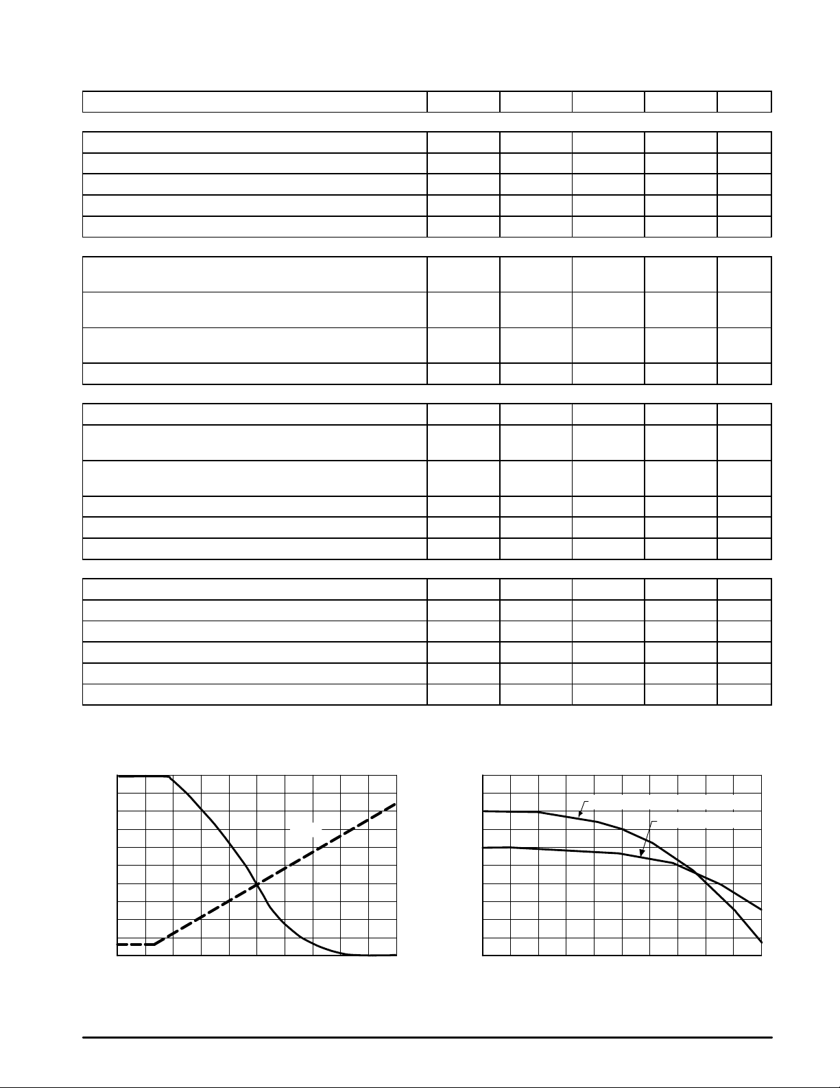
Figure 2. Monomax AGC Characteristics Figure 3. Video Output Response
AGC VOLTAGE, Pin 8 (V)
IF GAIN REDUCTION (dB)
AGC FEEDFORWARD, Pin 9 (V)
0 1.0 2.0 3.0 4.0 5.0 0 2.0 4.0 6.0 8.0 10
RELATIVE ATTENUATION (dB)
VIDEO OUTPUT RESPONSE (MHz)
0
–10
–20
–30
–40
–50
3
2
1
0
–1
–2
–3
–4
–5
–6
5.0
4.0
3.0
2.0
1.0
0
(Pin 9)
Video Out (Pin 24) with Max Contrast
Sound IF Out (Pin 28)
 Loading...