

Motorola MC12210D Datasheet
The MC12210 is a 2.5 GHz Bipolar monolithic serial input phase locked
loop (PLL) synthesizer with pulse–swallow function. It is designed to provide
the high frequency local oscillator signal of an RF transceiver in handheld
communication applications.
Motorola’s advanced Bipolar MOSAIC V technology is utilized for low
power operation at a minimum supply voltage of 2.7 V. The device is
designed for operation over 2.7 to 5.5 V supply range for input frequencies
up to 2.5 GHz with a typical current drain of 9.5 mA. The low power
consumption makes the MC12210 ideal for handheld battery operated
applications such as cellular or cordless telephones, wireless LAN or
personal communication services. A dual modulus prescaler is integrated to
provide either a 32/33 or 64/65 divide ratio.
For additional applications information, two
documents containing software (based on a Microsoft Excel spreadsheet)
and an Application Note are available. Please order DK305/D and DK306/D
from the Motorola Literature Distribution Center.
• Low Power Supply Current of 8.8 mA Typical for I
for I
P
• Supply Voltage of 2.7 to 5.5 V
• Dual Modulus Prescaler With Selectable Divide Ratios of 32/33 or 64/65
• On–Chip Reference Oscillator/Buffer
• Programmable Reference Divider Consisting of a Binary 14–Bit
Programmable Reference Counter
• Programmable Divider Consisting of a Binary 7–Bit Swallow Counter
and an 1 1–Bit Programmable Counter
• Phase/Frequency Detector With Phase Conversion Function
• Balanced Charge Pump Outputs
• Dual Internal Charge Pumps for Bypassing the First Stage of the Loop
Filter to Decrease Lock Time
• Outputs for External Charge Pump
• Operating Temperature Range of –40 to 85°C
• Space Efficient Plastic Surface Mount SOIC or TSSOP Packages
InterActiveApNote
and 0.7 mA Typical
CC
Order this document by MC12210/D
MECL PLL COMPONENTS
SERIAL PLL
FREQUENCY SYNTIESIZER
SEMICONDUCTOR
TECHNICAL DATA
16
1
D SUFFIX
PLASTIC PACKAGE
CASE 751B
(SO–16)
20
1
DT SUFFIX
PLASTIC PACKAGE
CASE 948E
(TSSOP–20)
MOSAIC V, Mfax and
MAXIMUM RATINGS
Parameter Symbol Value Unit
Power Supply Voltage, Pin 4 (Pin 5 in
20–lead package)
Power Supply Voltage, Pin 3 (Pin 4 in
20–lead package)
Storage Temperature Range Tstg –65 to 150 °C
NOTES: 1. Maximum Ratings are those values beyond which damage to the device may
occur. Functional operation should be restricted to the Recommended
Operating Conditions.
2.ESD data available upon request.
InterActiveApNote
(Note 1)
are trademarks of Motorola, Inc.
V
CC
V
p
–0.5 to 6.0 Vdc
VCC to 6.0 Vdc
ORDERING INFORMATION
Operating
Device
MC12210D
MC12210DT
Motorola, Inc. 1997 Rev 4
Temperature Range
TA = – 40° to +85°C
Package
SO–16
TSSOP–20
MC12210
φ
R
φ
P
f
BISW
FC
LE
DATA
OUT
16
15
14
13
12
11
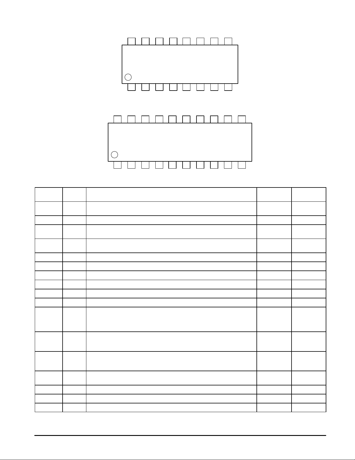
Pinout: 16–Lead Package (Top View)
1
2
3
4
5
6
OSCin
φ
20
OSCout
R
NC
19
φ
18
V
V
Do
FC
15
GND
LE
14
P
CC
P
f
BISW
OUT
17
16
Pinout: 20–Lead Package (Top View)
1
2
3
4
5
6
7
OSCin
NC
OSCout
V
V
Do
P
CC
GND
PIN NAMES
Pin I/O Function
OSCin I Oscillator input. A crystal may be connected between OSCin and OSCout. It is
OSCout O Oscillator output. Pin should be left open if external source is used 2 3
V
P
V
CC
Do O Internal charge pump output. Do remains on at all times 5 6
GND — Ground 6 7
LD O Lock detect, phase comparator output 7 8
f
IN
CLK I Clock input. Rising edge of the clock shifts data into the shift registers 9 11
DATA I Binary serial data input 10 13
LE I Load enable input (with internal pull up resistor). When LE is HIGH or OPEN, data
FC I Phase control select (with internal pull up resistor). When FC is LOW, the
BISW O Analog switch output. When LE is HIGH or OPEN (“analog switch is ON”) the
f
OUT
φP O Output for external charge pump. Standard CMOS output level 15 18
φR O Output for external charge pump. Standard CMOS output level 16 20
NC — No connect — 2, 9, 12, 19
highly recommended that an external source be ac coupled into this pin (see text).
— Power supply for charge pumps (VP should be greater than or equal to VCC) V
provides power to the Do, BISW and φP outputs
— Power supply voltage input. Bypass capacitors should be placed as close as
possible to this pin and be connected directly to the ground plane.
I Prescaler input. The VCO signal is AC–coupled into this pin 8 10
stored in the shift register is transferred into the appropriate latch (depending on
the level of control bit). Also, when LE is HIGH or OPEN, the output of the second
internal charge pump is connected to the BISW pin
characteristics of the phase comparator and charge pump are reversed. FC also
selects fp or fr on the f
output of the second charge pump is connected to the BISW pin. When LE is LOW,
BISW is high impedance
O Phase comparator input signal. When FC is HIGH, f
reference divider output; when FC is LOW, f
OUT
pin
=fp, programmable divider output
OUT
OUT
CLK
10
9
7
8
LD
f
IN
DATA
NC
CLK
13
12
11
8
9
10
LD
NC
f
=fr, programmable
IN
16–Lead Pkg
P
Pin No.
1 1
3 4
4 5
11 14
12 15
13 16
14 17
20–Lead Pkg
Pin No.
2
MOTOROLA RF/IF DEVICE DATA
OSCin
OSCout
CRYST AL
OSCILLA TOR
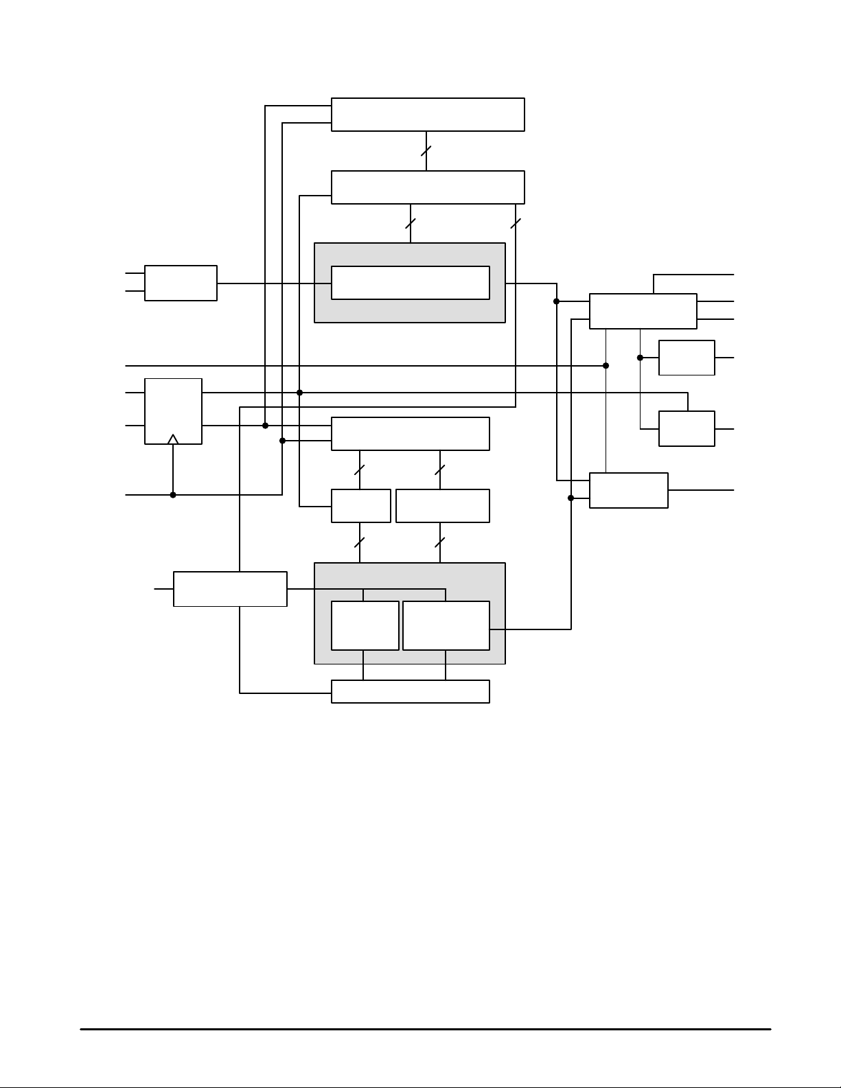
MC12210
Figure 1. MC12210 Block Diagram
15–BIT SHIFT REGISTER
15
15–BIT LATCH
14 1
PROGRAMMABLE REFERENCE DIVIDER
14–BIT REFERENCE COUNTER
fr
PHASE/FREQUENCY
DETECTOR
LD
φ
φ
P
R
FC
LE
DATA
CLK
CONTROL
BIT
f
IN
LE
DATA
PRESCALER
32/33 or 64/65
18–BIT SHIFT REGISTER
7 11
7–BIT
LATCH
7 11
PROGRAMMABLE DIVIDER
7–BIT
SWALLOW
A–COUNTER
11–BIT LATCH
11–BIT
PROGRAMMABLE
N–COUNTER
CONTROL LOGIC
CHARGE
PUMP 1
CHARGE
PUMP 2
DIVIDER
OUTPUT MUX
fp
Do
BISW
f
OUT
MOTOROLA RF/IF DEVICE DATA
3
MC12210
DATA ENTRY FORMAT
The three wire interface of DATA pin, CLK (clock) pin and LE (load enable) pin controls the serial data input of the 14–bit
programmable reference divider plus the prescaler setting bit, and the 18–bit programmable divider. A rising edge of the clock
shifts one bit of serial data into the internal shift registers. Depending upon the level of the control bit, stored data is transferred
into the latch when load enable pin is HIGH or OPEN.
Control bit: “H” = data is transferred into 15–bit latch of programmable reference divider
“L” = data is transferred into 18–bit latch of programmable divider
WARNING: Switching CLK or DA TA after the device is programmed may generate noise on the charge pump outputs which will
affect the VCO.
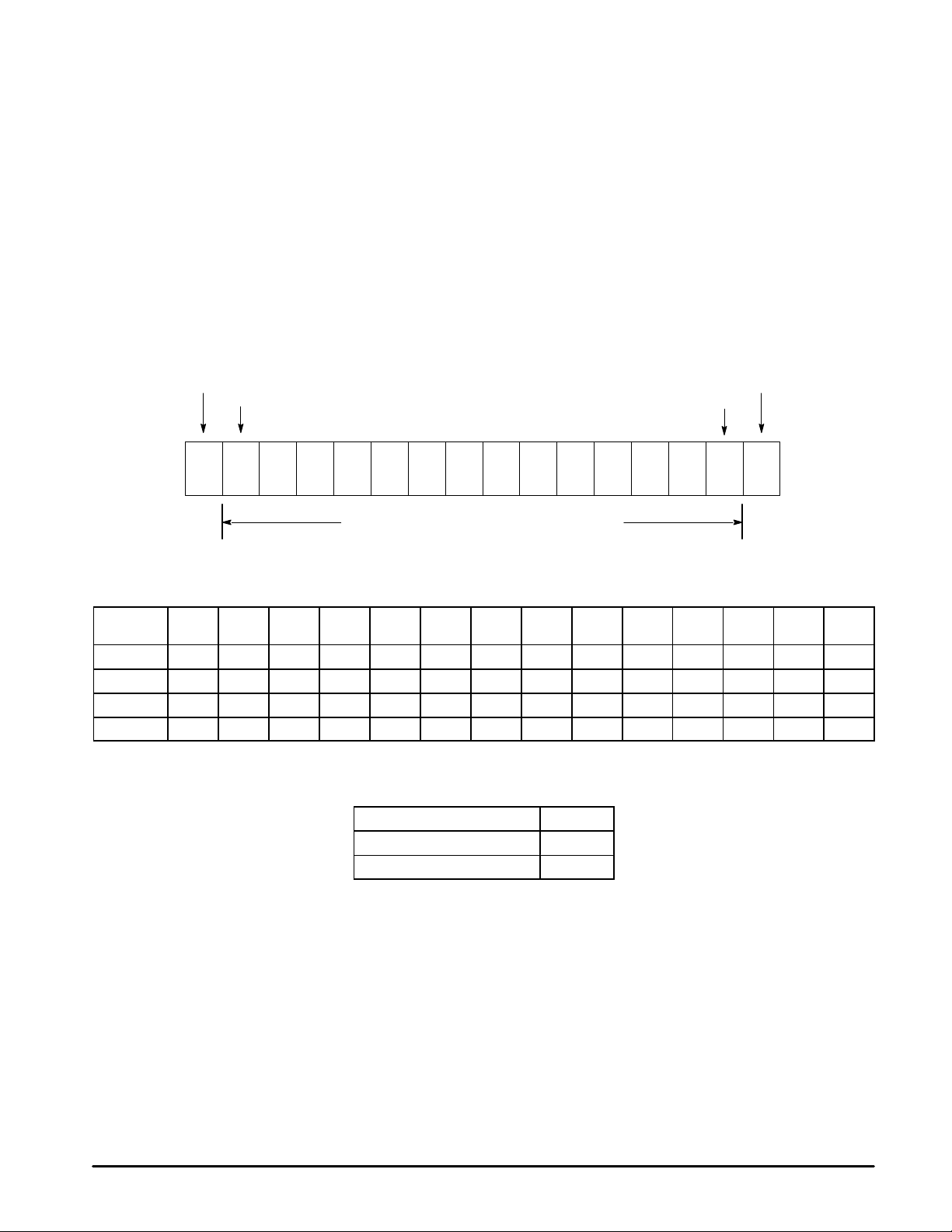
PROGRAMMABLE REFERENCE DIVIDER
16–bit serial data format for the programmable reference counter, “R–counter”, and prescaler select bit (SW) is shown below. If
the control bit is HIGH, data is transferred from the 15–bit shift register into the 15–bit latch which specifies the R divide ratio (8 to
16383) and the prescaler divide ratio (SW=0 for ÷64/65, SW=1 for ÷
For Control bit (C) = HIGH:
32/33). An R divide ratio less than 8 is prohibited.
SETTING BIT FOR PRESCALER DIVIDE RATIO (FIRST BIT)
MSB
R
R
R
R
R
R
R
S
8
9
10
11
12
13
14
W
SETTING BITS FOR DIVIDE RATIO OF PROGRAMMABLE
REFERENCE COUNTER (R–COUNTER)
R
R
R
5
6
7
CONTROL BIT (LAST BIT)
R
R
R
2
3
4
LSB
CR
1
DIVIDE RATIO OF PROGRAMMABLE REFERENCE (R) COUNTER
Divide
Ratio R
8 0 0 0 0 0 0 0 0 0 0 1 0 0 0
9 0 0 0 0 0 0 0 0 0 0 1 0 0 1
• • • • • • • • • • • • • • •
16383 1 1 1 1 1 1 1 1 1 1 1 1 1 1
14
R
13
R
12
R
R
11
10
R
R
9
R
8
R
7
R
6
R
5
R
4
R
3
R
2
PRESCALER SELECT BIT
Prescaler Divide Ratio P SW
64/65 0
32/33 1
R
1
4
MOTOROLA RF/IF DEVICE DATA
 Loading...