

Motorola MC10H179FN, MC10H179L Datasheet
SEMICONDUCTOR TECHNICAL DATA
The MC10H179 is a functional/pinout duplication of the standard MECL 10K
part, with 100% improvement in propagation delay and no increase in power
supply current.
• Power Dissipation, 300 mW Typical
• Improved Noise Margin 150 mV (Over Operating Voltage and
Temperature Range)
• Voltage Compensated
• MECL 10K–Compatible
MAXIMUM RATINGS
Characteristic Symbol Rating Unit
Power Supply (VCC = 0) V
Input Voltage (VCC = 0) V
Output Current— Continuous
— Surge
Operating Temperature Range T
Storage Temperature Range— Plastic
— Ceramic
I
T
EE
I
out
A
stg
–8.0 to 0 Vdc
0 to V
EE
50
100
0 to +75 °C
–55 to +150
–55 to +165
Vdc
mA
°C
°C
ELECTRICAL CHARACTERISTICS (VEE = –5.2 V ±5%) (See Note)
0° 25° 75°
Characteristic Symbol Min Max Min Max Min Max Unit
Power Supply Current I
Input Current High
Pins 5 and 9
Pins 4, 7 and 11
Pin 14
Pin 12
Pins 10 and 13
Input Current Low I
High Output Voltage V
Low Output Voltage V
High Input Voltage V
Low Input Voltage V
I
E
inH
inL
OH
OL
IH
— 79 — 72 — 79 mA
—
465
—
545
—
705
—
790
—
870
0.5 — 0.5 — 0.3 — µA
–1.02 –0.84 –0.98 –0.81 –0.92 –0.735 Vdc
–1.95 –1.63 –1.95 –1.63 –1.95 –1.60 Vdc
–1.17 –0.84 –1.13 –0.81 –1.07 –0.735 Vdc
–1.95 –1.48 –1.95 –1.48 –1.95 –1.45 Vdc
IL
—
275
—
320
—
415
—
465
—
510
—
—
—
—
—
275
320
415
465
510
AC PARAMETERS
Propagation Delay
P to P
G
G, P, Cn to
Cn or G
G
Rise Time t
Fall Time t
NOTE:
Each MECL 10H series circuit has been designed to meet the dc specifications shown in the test table,
after thermal equilibrium has been established. The circuit is in a test socket or mounted on a printed
circuit board and transverse air flow greater than 500 Ifpm is maintained. Outputs are terminated through
a 50–ohm resistor to –2.0 volts.
t
pd
0.4
1.4
0.4
1.5
0.5
0.6
2.3
0.7
2.4
0.8
0.5 1.7 0.5 1.8 0.5 1.9 ns
r
0.5 1.7 0.5 1.8 0.5 1.9 ns
f
1.7
2.6
µA
ns
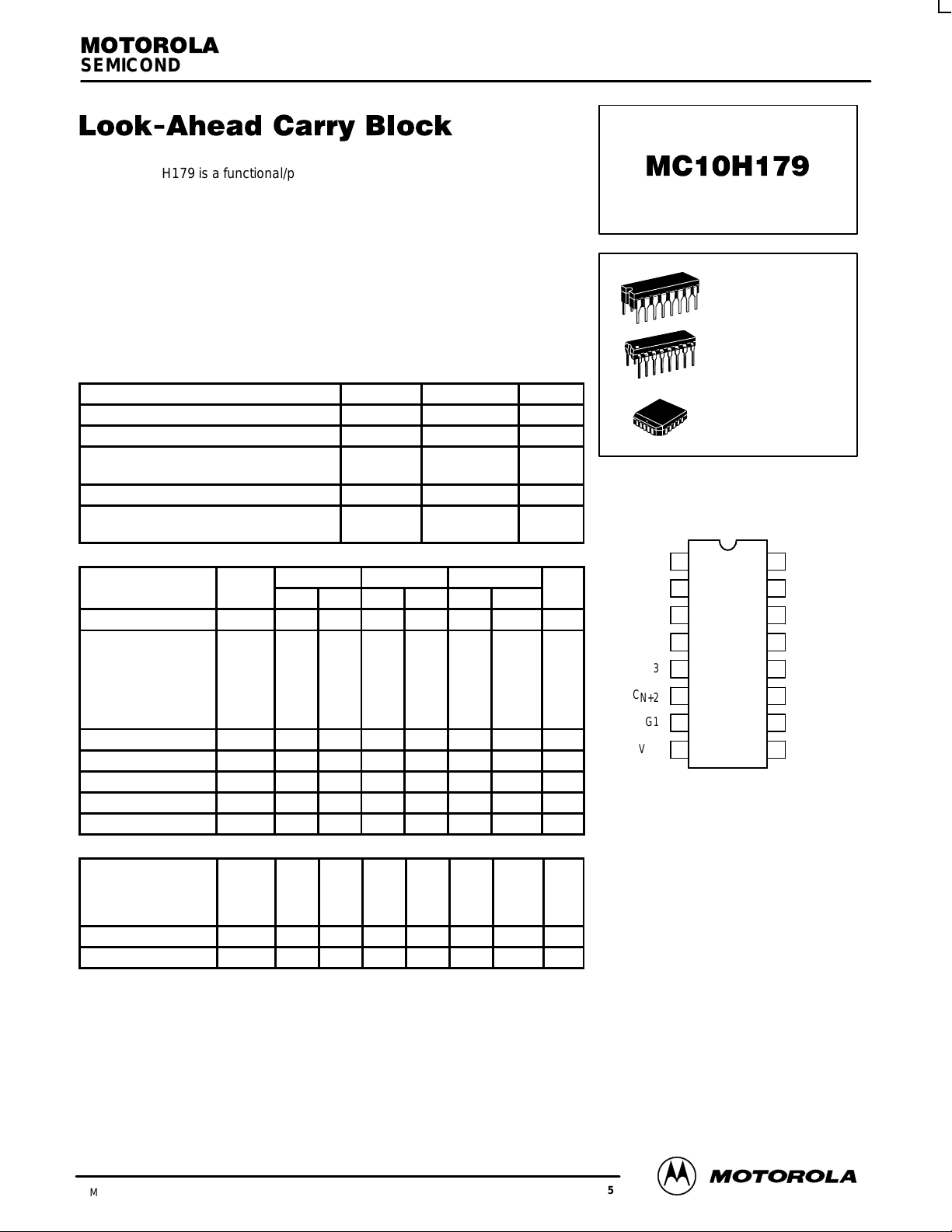
L SUFFIX
CERAMIC PACKAGE
CASE 620–10
P SUFFIX
PLASTIC PACKAGE
CASE 648–08
FN SUFFIX
PLCC
CASE 775–02
DIP
PIN ASSIGNMENT
V
CC1
G
G
C
N+4
G0
G3
C
N+2
G1
V
EE
Pin assignment is for Dual–in–Line Package.
For PLCC pin assignment, see the Pin Conversion
T ables on page 6–11 of the Motorola MECL Data
1
2
3
4
5
6
7
8
Book (DL122/D).
16
15
14
13
12
11
10
V
CC2
P
G
P0
P3
P2
C
N
P1
G2
9
3/93
Motorola, Inc. 1996
2–135
REV 5
MC10H179
G3 5
P3 13
G2 9
P2 12
CN 11
G1 7
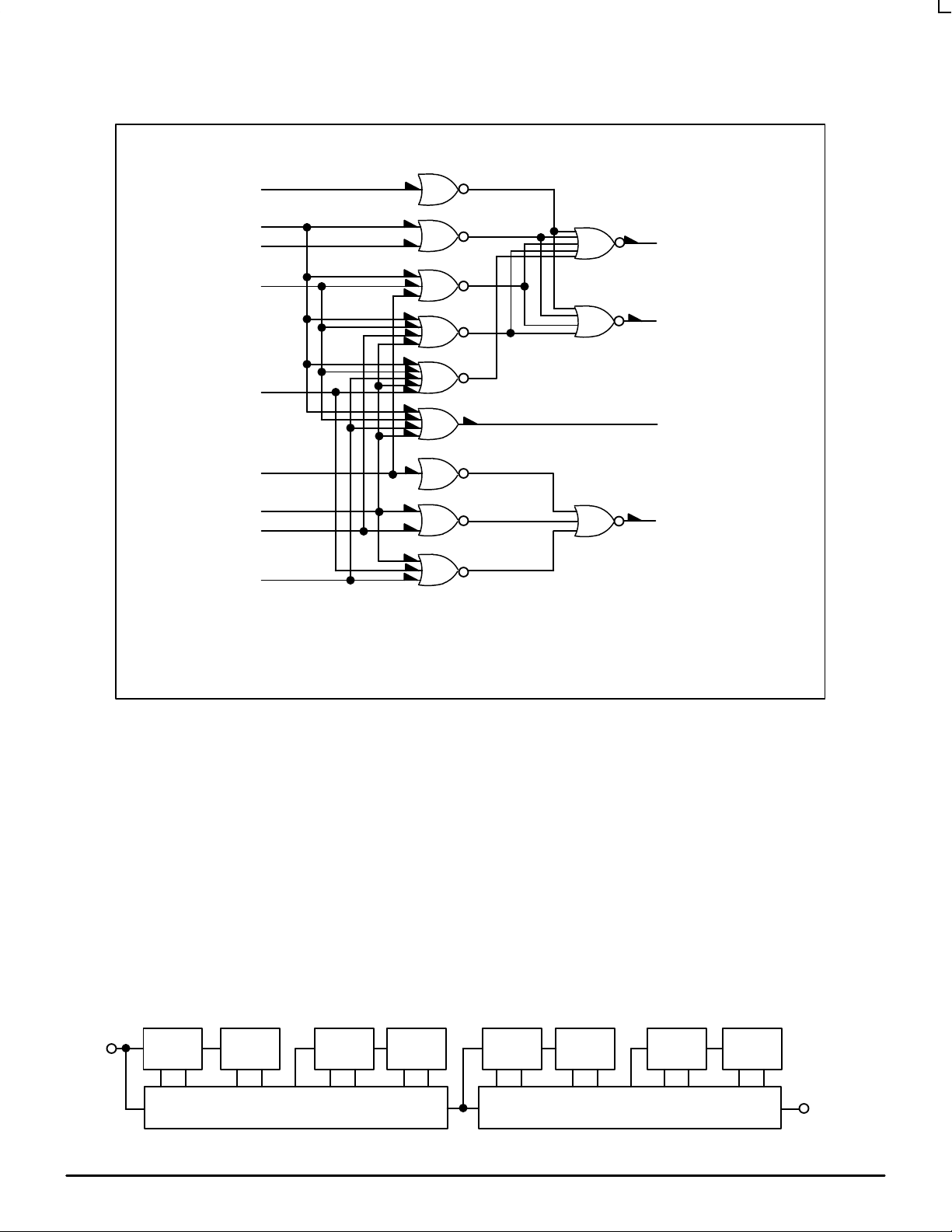
LOGIC DIAGRAM
3 C
2 G
15 P
N+4
G
G
P1 10
G0 4
P0 14
PG= P0 + P1 + P2 + P3
GG= (G0 + P1 + P2 + P3) (G1 + P2 + P3) (G2 + P3) G3
C
=(CN + P0 + P1) (G0 + P1) G1
N+2
C
=(CN + P0 + P1 + P2 + P3) (G0 + P1 + P2 + P3) (G1 + P2 + P3)
N+4
(G2 + P3) G3
TYPICAL APPLICATIONS
The MC10H179 is a high–speed, low–power, standard
MECL complex function that is designed to perform the
look–ahead carry function. This device can be used with
the MC10H181 4–bit ALU directly , or with the MC10H180
dual arithmetic unit in any computer, instrumentation or
digital communication application requiring high speed
arithmetic operation on long words.
When used with the MC10H181, the MC10H179
performs a second order or higher look–ahead. Figure 2
6 C
N+2
V
= PIN 1
CC1
V
= PIN 16
CC2
VEE= PIN 8
shows a 16–bit look–ahead carry arithmetic unit. Second
order carry is valuable for longer binary words. As an
example, addition of two 32–bit words is improved from
30 nanoseconds with ripple–carry techniques. A block
diagram of a 32–bit ALU is shown in Figure 1. The
MC10H179 may also be used in many other applications.
It can, for example, reduce system package count when
used to generate functions of several variables.
FIGURE 1 — 32–BIT ALU WITH CARRY LOOK–AHEAD
C
in
MOTOROLA MECL Data
ALU
CnC
n+4
PG
C
n
ALU
C
n
PG
C
n+2
MC10H179
ALU
CnC
n+4
PG
ALU
C
n
PG
C
n+4
2–136
ALU
CnC
n+4
PG
C
n
ALU
C
n
PG
C
n+2
MC10H179
ALU
CnC
n+4
PG
C
n
PG
Add Time =
ALU
18 ns typ
C
n+4
DL122 — Rev 6
C
out
 Loading...