

D0
D3 D4 D5 V
CCO
Q5 Q4 V
CCO
Q3
Q2
V
CC
V
CCO
COUT
COUT
CLOUT
V
CCO
Q1Q0V
CCO
D1
MR
CLIN
CIN
CLK
V
EE
S1
S2
D2
4
3
2
1
28
27
26
25
24
23
22
21
20
19
18
17
16
15
14
13
12
11109
7
8
6
5
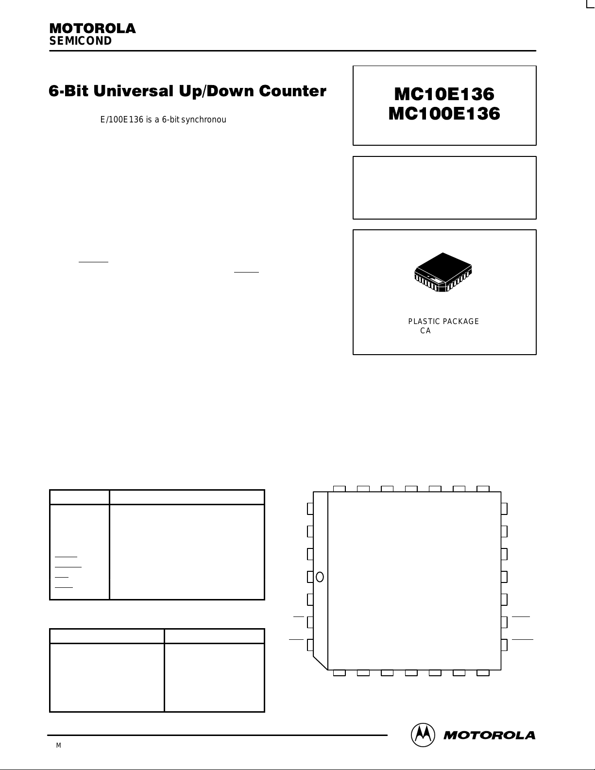
Pinout: 28-lead PLCC
(Top View)
* All VCC and V
CCO
pins are tied together on the die.
SEMICONDUCTOR TECHNICAL DATA
2–1
REV 2
Motorola, Inc. 1996
5/95
The MC10E/100E136 is a 6-bit synchronous, presettable, cascadable
universal counter. The device generates a look-ahead-carry output and
accepts a look-ahead-carry input. These two features allow for the
cacading of multiple E136’s for wider bit width counters that operate at
very nearly the same frequency as the stand alone counter.
• 550 MHz Count Frequency
• Fully Synchronous Up and Down Counting
• Internal 75 kΩ Input Pulldown Resistors
• Look-Ahead-Carry Input and Output
• Asynchronous Master Reset
• Extended 100E V
EE
Range of –4.2 V to –5.46 V
The CLOUT
output will pulse LOW for one clock cycle one count
before the E136 reaches terminal count. The COUT
output will pulse
LOW for one clock cycle when the counter reaches terminal count. For
more information on utilizing the look-ahead-carry features of the device
please refer to the applications section of this data sheet. The differential
COUT output facilitates the E136’s use in programmable divider and
self-stopping counter applications.
Unlike the H136 and other similar universal counter designs the E136
carry out and look-ahead-carry out signals are registered on chip. This
design alleviates the glitch problem seen on many counters where the carry out signals are merely gated. Because of this
architecture there are some minor functional differences between the E136 and H136 counters. The user, regardless of
familiarity with the H136, should read this data sheet carefully . Note specifically (see logic diagram) the operation of the carry out
outputs and the look-ahead-carry in input when utilizing the master reset.
When left open all of the input pins will be pulled LOW via an input pulldown resistor. The master reset is an asynchronous
signal which when asserted will force the Q outputs LOW.
The Q outputs need not be terminated for the E136 to function properly , in fact if these outputs will not be used in a system it is
recommended to save power and minimize noise that they be left open. This practice will minimize switching noise which can
reduce the maximum count frequency of the device or significantly reduce margins against other noise in the system.
PIN NAMES
Pin Function
D0 – D
5
Preset Data Inputs
Q0 – Q
5
Data Inputs
S1, S2 Mode Control Pins
MR Master Reset
CLK Clock Input
COUT, COUT Carry-Out Output (Active LOW)
CLOUT Look-Ahead-Carry Out (Active LOW)
CIN Carry-In Input (Active LOW)
CLIN Look-Ahead-Carry In Input (Active LOW)
FUNCTION TABLE (Expanded truth table on page 2–4)
S1
S2 CIN MR CLK Function
L
L
L
H
H
H
X
L
H
H
L
L
H
X
X
L
H
L
H
X
X
L
L
L
L
L
L
H
Z
Z
Z
Z
Z
Z
X
Preset Parallel Data
Increment (Count Up)
Hold Count
Decrement (Count Down)
Hold Count
Hold Count
Reset (Qn = LOW)
6-BIT UNIVERSAL
UP/DOWN COUNTER
FN SUFFIX
PLASTIC PACKAGE
CASE 776-02
MC10E136 MC100E136
MOTOROLA ECLinPS and ECLinPS Lite
DL140 — Rev 4
2–2
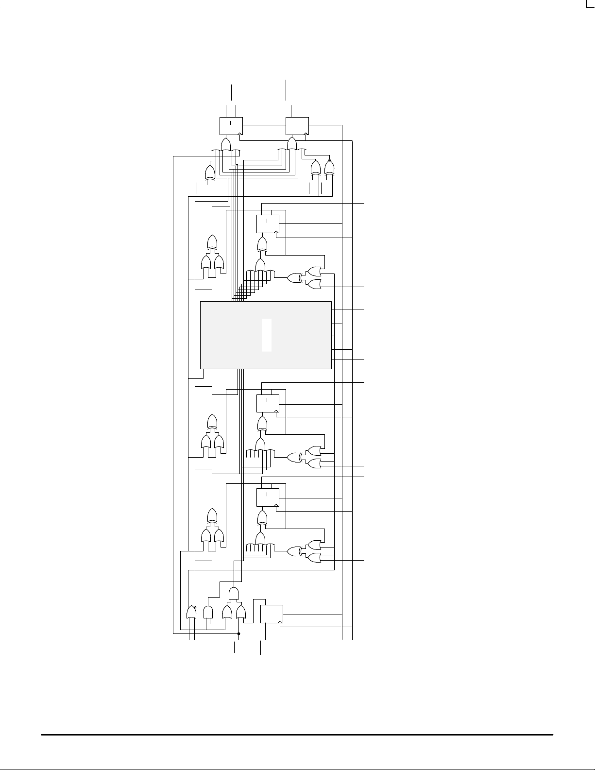
E136 Universal Up/Down Counter Logic Diagram
S1
S2
CIN
CLIN
MR
CLK
D Q
S
D Q
R
Q
D Q
R
Q
D Q
R
Q
D Q
S
Q
D Q
S
D0 Q0 D1 Q1 D2 – D4 Q2 – Q4 D5 Q5
COUT
QM0
QM1
QM0
COUT
CLOUT
Bits 2 – 4
Note that this diagram is provided for understanding of logic operation only. It should not be used for propagation delays as many gate functions
are achieved internally without incurring a full gate delay.
MC10E136 MC100E136
2–3 MOTOROLAECLinPS and ECLinPS Lite
DL140 — Rev 4
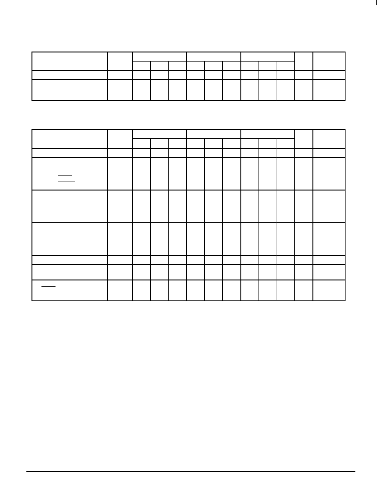
DC CHARACTERISTICS (V
EE
= VEE(min) to VEE(max); VCC = V
CCO
= GND)
0°C 25°C 85°C
Characteristic Symbol Min Typ Max Min Typ Max Min Typ Max Unit Condition
Input HIGH Current I
IH
— — 150 — — 150 — — 150 µA
Power Supply Current
10E
100E
I
EE
——125
125
150
150——
125
125
150
150——
125
140
150
170
mA
AC CHARACTERISTICS (V
EE
= VEE(min) to VEE(max); VCC = V
CCO
= GND)
0°C 25°C 85°C
Characteristic Symbol Min Typ Max Min Typ Max Min Typ Max Unit Condition
Maximum Count Frequency f
COUNT
550 650 — 550 650 — 550 650 — MHz
Propagation Delay to Output
CLK to Q
MR to Q
CLK to COUT
CLK to CLOUT
t
PLH
t
PHL
850
850
800
825
1150
1150
1150
1150
1450
1450
1300
1400
850
850
800
825
1150
1150
1150
1150
1450
1450
1300
1400
850
850
800
825
1150
1150
1150
1150
1450
1450
1300
1400
ps
Setup Time
S1, S2
D
CLIN
CIN
t
s
1000
800
150
800
650
400
0
400
—
—
—
—
1000
800
150
800
650
400
0
400
—
—
—
—
1000
800
150
800
650
400
0
400
—
—
—
—
ps
Hold Time
S1, S2
D
CLIN
CIN
t
h
150
150
300
150
–200
–250
0
–250
—
—
—
—
150
150
300
150
–200
–250
0
–250
—
—
—
—
150
150
300
150
–200
–250
0
–250
—
—
—
—
ps
Reset Recovery Time t
RR
1000 700 — 1000 700 — 1000 700 — ps
Minimum Pulse Width
CLK, MR
t
PW
700 400 — 700 400 — 700 400 —
ps
Rise/Fall Times
COUT
Other
t
r
t
f
275
300——
600
700
275
300——
600
700
275
300——
600
700
ps
20% - 80%

MC10E136 MC100E136
MOTOROLA ECLinPS and ECLinPS Lite
DL140 — Rev 4
2–4
EXPANDED TRUTH TABLE
Function S1 S2 MR CIN CLIN CLK D5 D4 D3 D2 D1 D0 Q5 Q4 Q3 Q2 Q1 Q0 COUT CLOUT
Preset L L L X X Z L L L L H H L L L L H H H H
Down H
H
H
H
L
L
L
L
L
L
L
L
L
L
L
L
L
L
L
L
Z
Z
Z
Z
X
X
X
X
X
X
X
X
X
X
X
X
X
X
X
X
X
X
X
X
X
X
X
X
L
L
L
H
L
L
L
H
L
L
L
H
L
L
L
H
H
L
L
H
L
H
L
H
H
H
L
H
H
L
H
H
Preset L L L X X Z H H H H L L H H H H L L H H
Up L
L
L
L
L
L
H
H
H
H
H
H
L
L
L
L
L
L
L
L
L
L
L
L
L
L
L
L
L
L
Z
Z
Z
Z
Z
Z
X
X
X
X
X
X
X
X
X
X
X
X
X
X
X
X
X
X
X
X
X
X
X
X
X
X
X
X
X
X
X
X
X
X
X
X
H
H
H
L
L
L
H
H
H
L
L
L
H
H
H
L
L
L
H
H
H
L
L
L
L
H
H
L
L
H
H
L
H
L
H
L
H
H
L
H
H
H
H
L
H
H
H
H
Hold HHH
H
L
L
X
X
X
X
ZZXXXXXXXXXXXXLLLLLLLLHHLLH
H
H
H
Down
Hold
Down
Hold
Hold
H
H
H
H
H
H
H
H
L
L
L
L
L
L
L
L
L
L
L
L
L
L
L
L
L
H
L
H
H
H
L
L
L
L
L
L
L
H
H
L
Z
Z
Z
Z
Z
Z
Z
Z
X
X
X
X
X
X
X
X
X
X
X
X
X
X
X
X
X
X
X
X
X
X
X
X
X
X
X
X
X
X
X
X
X
X
X
X
X
X
X
X
X
X
X
X
X
X
X
X
L
L
L
L
L
L
L
L
L
L
L
L
L
L
L
L
L
L
L
L
L
L
L
L
L
L
L
L
L
L
L
L
L
L
L
L
L
L
L
L
H
H
L
L
L
L
L
L
H
H
L
H
H
H
L
L
L
H
H
H
H
H
H
H
Hold
Preset
Up
Hold
Up
Hold
Hold
H
L
L
L
L
L
L
L
L
H
L
H
H
H
H
H
H
H
L
L
L
L
L
L
L
L
L
L
X
L
L
H
L
H
H
L
L
X
L
L
L
L
L
H
L
Z
Z
Z
Z
Z
Z
Z
Z
Z
X
H
X
X
X
X
X
X
X
X
H
X
X
X
X
X
X
X
X
H
X
X
X
X
X
X
X
X
H
X
X
X
X
X
X
X
X
L
X
X
X
X
X
X
X
X
L
X
X
X
X
X
X
X
L
H
H
H
H
H
H
H
H
L
H
H
H
H
H
H
H
H
L
H
H
H
H
H
H
H
H
L
H
H
H
H
H
H
H
H
L
L
L
H
H
H
H
H
H
L
L
H
L
L
H
H
H
H
L
H
H
H
H
L
H
H
L
H
H
H
L
H
H
H
H
H
Up L
L
L
L
H
H
H
H
L
L
L
L
L
L
L
L
L
L
L
L
Z
Z
Z
Z
X
X
X
X
X
X
X
X
X
X
X
X
X
X
X
X
X
X
X
X
X
X
X
X
L
L
L
L
L
L
L
L
L
L
L
L
L
L
L
L
L
L
H
H
L
H
L
H
H
H
H
H
H
H
H
H
Reset X X H X X X X X X X X X L L L L L L H H
Z = Low to High Transition

MC10E136 MC100E136
2–5 MOTOROLAECLinPS and ECLinPS Lite
DL140 — Rev 4
APPLICATIONS INFORMATION
Overview
The MC10E/100E136 is a 6-bit synchronous, presettable,
cascadable universal counter. Using the S1 and S2 control
pins the user can select between preset, count up, count
down and hold count. The master reset pin will reset the
internal counter, and set the COUT
, CLOUT, and CLIN
flip-flops. Unlike previous 136 type counters the carry out
outputs will go to a high state during the preset operation. In
addition since the carry out outputs are registered they will
not go low if terminal count is loaded into the register. The
look-ahead-carry out output functions similarly.
Note from the schematic the use of the master information
from the least significant bits for control of the two carry out
functions. This architecture not only reduces the carry out
delay, but is essential to incorporate the registered carry out
functions. In addition to being faster, because these functions
are registered the resulting carry out signals are stable and
glitch free.
Cascading Multiple E136 Devices
Many applications require counters significantly larger
than the 6 bits available with the E136. For these applications
several E136 devices can be cascaded to increase the bit
width of the counter to meet the needs of the application.
In the past cascading several 136 type universal counters
necessarily impacted the maximum count frequency of the
resulting counter chain. This performance impact was the
result of the terminal count signal of the lower order counters
having to ripple through the entire counter chain. As a result
past counters of this type were not widely used in large bit
counter applications.
An alternative counter architecture similar to the E016
binary counter was implemented to alleviate the need to
ripple propagate the terminal count signal. Unfortunately
these types of counters require external gating for cascading
designs of more than two devices. In addition to requiring
additional components, these external gates limit the
cascaded count frequency to a value less than the free
running count frequency of a single counter. Although there is
a performance impact with this type of architecture it is minor
compared to the impact of the ripple propagate designs. As a
result the E016 type counters have been used extensively in
applications requiring very high speed, wide bit width
synchronous counters.
Motorola has incorporated several improvements to past
universal counter designs in the E136 universal counter.
These enhancements make the E136 the unparalleled leader
in its class. With the addition of look-ahead-carry features on
the terminal count signal, very large counter chains can be
designed which function at very nearly the same clock
frequency as a single free running device. More importantly
these counter chains require no external gating. Figure 1
below illustrates the interconnect scheme for using the
look-ahead-carry features of the E136 counter.
Figure 1. 24-bit Cascaded E136 Counter
Q0 –> Q5
D0 –> D5
CLK
Q0 –> Q5
D0 –> D5
CLK
Q0 –> Q5
D0 –> D5
CLK
LSB
Q0 –> Q5
D0 –> D5
CLOUT
COUT
CLIN
CIN
CLK
CLOUT
COUT
CLK
000001000000111111111110111101
CLOCK
“LO”
“LO” “LO”
CLOUT
COUT
CLIN
CIN
CLOUT
COUT
CLIN
CIN
MSB
CLOUT
COUT
CLIN
CIN

MC10E136 MC100E136
MOTOROLA ECLinPS and ECLinPS Lite
DL140 — Rev 4
2–6
Figure 2. Look-Ahead-Carry Input Structure
ACTIVE
LOW
CLK
CIN
CLIN
QD
Note from the waveforms that the look-ahead-carry output
(CLOUT
) pulses low one clock pulse before the counter
reaches terminal count. Also note that both CLOUT
and the
carry out pin (COUT
) of the device pulse low for only one
clock period. The input structure for look-ahead-carry in
(CLIN) and carry in (CIN) is pictured in Figure 2.
The CLIN
input is registered and then ORed with the CIN
input. From the truth table one can see that both the CIN and
the CLIN
inputs must be in a LOW state for the E136 to be
enabled to count (either count up or count down). The CLIN
inputs are driven by the CLOUT output of the lowest order
E136 and therefore are only asserted for a single clock
period. Since the CLIN
input is registered it must be asserted
one clock period prior to the CIN
input.
If the counter previous to a given counter is at terminal
count its COUT
output and thus the CIN input of the given
counter will be in the “LOW” state. This signals the given
counter that it will need to count one upon the next terminal
count of the least significant counter (LSC). The CLOUT
output of the LSC will pulse low one clock period before it
reaches terminal count. This CLOUT
signal will be clocked
into the CLIN
input of the higher order counters on the
following positive clock transition. Since both CIN
and CLIN
are in the LOW state the next clock pulse will cause the least
significant counter to roll over and all higher order counters, if
signaled by their CIN
inputs, to count by one.
Figure 3. 6-bit Programmable Divider
“LO”
S0
S1
Q0 –> Q5
D0 –> D5
COUT
COUT
CLK
CLOCK
During the clock pulse in which the higher order counter is
counting by one the CLIN
is clocking in the high signal
presented by the CLOUT
of the LSC. The CIN’s in the higher
order counter will ripple propagate through the chain to
update the count status for the next occurrence of terminal
count on the LSC. This ripple propagation will not affect the
count frequency as it has 26–1 or 63 clock pulses to ripple
through without affecting the count operation of the chain.
The only limiting factor which could reduce the count
frequency of the chain as compared to a free running single
device will be the setup time of the CLIN
input. This limit will
consist of the CLK to CLOUT
delay of the E136 plus the CLIN
setup time plus any path length differences between the
CLOUT
output and the clock.
Programmable Divider
Using external feedback of the COUT
pin, the E136 can be
configured as a programmable divider. Figure 3 illustrates the
configuration for a 6-bit count down programmable divider. If
for some reason a count up divider is preferred the COUT
signal is simply fed back to S2 rather than S1. Examination of
the truth table for the E136 shows that when both S1 and S2
are LOW the counter will parallel load on the next positive
transition of the clock. If the S2 input is low and the S1 input is
high the counter will be in the count down mode and will
count towards an all zero state upon successive clock
pulses. Knowing this and the operation of the COUT
output it
becomes a trivial matter to build programmable dividers.
For a programmable divider one wants to load a
predesignated number into the counter and count to terminal
count. Upon terminal count the counter should automatically
reload the divide number. With the architecture shown in
Figure 3 when the counter reaches terminal count the COUT
output and thus the S1 input will go LOW, this combined with
the low on S2 will cause the counter to load the inputs
present on D0-D5. Upon loading the divide value into the
counter COUT
will go HIGH as the counter is no longer at
terminal count thereby placing the counter back into the
count mode.
Table 1. Preset Inputs Versus Divide Ratio
Divide Preset Data Inputs
Ratio D5 D4 D3 D2 D1 D0
2
3
4
5
•
•
36
37
38
•
•
62
63
64
L
L
L
L
•
•
H
H
H
•
•
H
H
H
L
L
L
L
•
•
L
L
L
•
•
H
H
H
L
L
L
L
•
•
L
L
L
•
•
H
H
H
L
L
L
H
•
•
L
H
H
•
•
H
H
H
L
H
H
L
•
•
H
L
L
•
•
L
H
H
H
L
H
L
•
•
H
L
H
•
•
H
L
H

MC10E136 MC100E136
2–7 MOTOROLAECLinPS and ECLinPS Lite
DL140 — Rev 4
Figure 4. Programmable Divider Waveforms
S1
COUT
CLOCK
DIVIDE BY 37
LOAD
000000000001000010000011100010100011
100100
• • •
• • •
• • •
LOAD
The exercise of building a programmable divider then
becomes simply determining what value to load into the
counter to accomplish the desired division. Since the load
operation requires a clock pulse, to divide by N, N–1 must be
loaded into the counter. A single E136 device is capable of
divide ratios of 2 to 64 inclusive, Table 1 outlines the load
values for the various divide ratios. Figure 4 presents the
waveforms resulting from a divide by 37 operation. Note that
the availability of the COUT complimentary output COUT
allows the user to choose the polarity of the divide by output.
For single device programmable counters the E016
counter is probably a better choice than the E136. The E016
has an internal feedback to control the reloading of the
counter, this not only simplifies board design but also will
result in a faster maximum count frequency.
For programmable dividers of larger than 8 bits the
superiority of the E016 diminishes, and in fact for very wide
dividers the E136 will provide the capability of a faster count
frequency. This potential is a result of the cascading features
mentioned previously in this document. Figure 5 shows the
architecture of a 24-bit programmable divider implemented
using E136 counters. Note the need for one external gate to
control the loading of the entire counter chain. An ideal
device for the external gating of this architecture would be the
4-input OR function in the 8-lead SOIC ECLinPS Lite family .
However the final decision as to what device to use for the
external gating requires a balancing of performance needs,
cost and available board space. Note that because of the
need for external gating the maximum count frequency of a
given sized programmable divider will be less than that of a
single cascaded counter.
Figure 5. 24-bit Programmable Divider Architecture
S1S1S1S1
Q0 –> Q5
D0 –> D5
CLK
Q0 –> Q5
D0 –> D5
CLK
Q0 –> Q5
D0 –> D5
CLK
LSB
Q0 –> Q5
D0 –> D5
CLOUT
COUT
CLIN
CIN
CLK
CLOCK
“LO”
“LO” “LO”
CLOUT
COUT
CLIN
CIN
CLOUT
COUT
CLIN
CIN
MSB
CLOUT
COUT
CLIN
CIN

MC10E136 MC100E136
MOTOROLA ECLinPS and ECLinPS Lite
DL140 — Rev 4
2–8
OUTLINE DIMENSIONS
FN SUFFIX
PLASTIC PLCC PACKAGE
CASE 776–02
ISSUE D
0.007 (0.180) T L
–M
SNSM
0.007 (0.180) T L
–M
SNSM
0.007 (0.180) T L
–M
SNSM
0.010 (0.250) T L
–M
SNSS
0.007 (0.180) T L
–M
SNSM
0.010 (0.250) T L
–M
SNSS
0.007 (0.180) T L
–M
SNSM
0.007 (0.180) T L
–M
SNSM
0.004 (0.100)
SEATING
PLANE
-T-
12.32
12.32
4.20
2.29
0.33
0.66
0.51
0.64
11.43
11.43
1.07
1.07
1.07
—
2
°
10.42
1.02
12.57
12.57
4.57
2.79
0.48
0.81
—
—
11.58
11.58
1.21
1.21
1.42
0.50
10
°
10.92
—
1.27 BSC
A
B
C
E
F
G
H
J
K
R
U
V
W
X
Y
Z
G1
K1
MIN MINMAX MAX
INCHES MILLIMETERS
DIM
NOTES:
1. DATUMS -L-, -M-, AND -N- DETERMINED
WHERE TOP OF LEAD SHOULDER EXITS
PLASTIC BODY AT MOLD PARTING LINE.
2. DIM G1, TRUE POSITION TO BE MEASURED
AT DATUM -T-, SEATING PLANE.
3. DIM R AND U DO NOT INCLUDE MOLD FLASH.
ALLOWABLE MOLD FLASH IS 0.010 (0.250)
PER SIDE.
4. DIMENSIONING AND TOLERANCING PER ANSI
Y14.5M, 1982.
5. CONTROLLING DIMENSION: INCH.
6. THE PACKAGE TOP MAY BE SMALLER THAN
THE PACKAGE BOTTOM BY UP TO 0.012
(0.300). DIMENSIONS R AND U ARE
DETERMINED AT THE OUTERMOST
EXTREMES OF THE PLASTIC BODY
EXCLUSIVE OF MOLD FLASH, TIE BAR
BURRS, GATE BURRS AND INTERLEAD
FLASH, BUT INCLUDING ANY MISMATCH
BETWEEN THE TOP AND BOTTOM OF THE
PLASTIC BODY.
7. DIMENSION H DOES NOT INCLUDE DAMBAR
PROTRUSION OR INTRUSION. THE DAMBAR
PROTRUSION(S) SHALL NOT CAUSE THE H
DIMENSION TO BE GREATER THAN 0.037
(0.940). THE DAMBAR INTRUSION(S) SHALL
NOT CAUSE THE H DIMENSION TO BE
SMALLER THAN 0.025 (0.635).
VIEW S
B
U
Z
G1
X
VIEW D-D
H
K
F
VIEW S
G
C
Z
A
R
E
J
0.485
0.485
0.165
0.090
0.013
0.026
0.020
0.025
0.450
0.450
0.042
0.042
0.042
—
2
°
0.410
0.040
0.495
0.495
0.180
0.110
0.019
0.032
—
—
0.456
0.456
0.048
0.048
0.056
0.020
10
°
0.430
—
0.050 BSC
-N-
Y BRK
D
D
W
-M-
-L-
28 1
V
G1
K1

MC10E136 MC100E136
2–9 MOTOROLAECLinPS and ECLinPS Lite
DL140 — Rev 4
Motorola reserves the right to make changes without further notice to any products herein. Motorola makes no warranty , representation or guarantee regarding
the suitability of its products for any particular purpose, nor does Motorola assume any liability arising out of the application or use of any product or circuit, and
specifically disclaims any and all liability , including without limitation consequential or incidental damages. “Typical” parameters which may be provided in Motorola
data sheets and/or specifications can and do vary in different applications and actual performance may vary over time. All operating parameters, including “Typicals”
must be validated for each customer application by customer’s technical experts. Motorola does not convey any license under its patent rights nor the rights of
others. Motorola products are not designed, intended, or authorized for use as components in systems intended for surgical implant into the body, or other
applications intended to support or sustain life, or for any other application in which the failure of the Motorola product could create a situation where personal injury
or death may occur. Should Buyer purchase or use Motorola products for any such unintended or unauthorized application, Buyer shall indemnify and hold Motorola
and its officers, employees, subsidiaries, affiliates, and distributors harmless against all claims, costs, damages, and expenses, and reasonable attorney fees
arising out of, directly or indirectly, any claim of personal injury or death associated with such unintended or unauthorized use, even if such claim alleges that
Motorola was negligent regarding the design or manufacture of the part. Motorola and are registered trademarks of Motorola, Inc. Motorola, Inc. is an Equal
Opportunity/Affirmative Action Employer.
How to reach us:
USA/EUROPE/Locations Not Listed: Motorola Literature Distribution; JAPAN: Nippon Motorola Ltd.; Tatsumi–SPD–JLDC, 6F Seibu–Butsuryu–Center,
P.O. Box 20912; Phoenix, Arizona 85036. 1–800–441–2447 or 602–303–5454 3–14–2 Tatsumi Koto–Ku, Tokyo 135, Japan. 03–81–3521–8315
MFAX: RMFAX0@email.sps.mot.com – TOUCHTONE 602–244–6609 ASIA/PACIFIC: Motorola Semiconductors H.K. Ltd.; 8B Tai Ping Industrial Park,
INTERNET: http://Design–NET.com 51 Ting Kok Road, Tai Po, N.T., Hong Kong. 852–26629298
MC10E136/D
*MC10E136/D*
◊
 Loading...