

Motorola MC10E136FNR2, MC10E136FN, MC100E136FNR2, MC100E136FN Datasheet
D0
D3 D4 D5 V
CCO
Q5 Q4 V
CCO
Q3
Q2
V
CC
V
CCO
COUT
COUT
CLOUT
V
CCO
Q1Q0V
CCO
D1
MR
CLIN
CIN
CLK
V
EE
S1
S2
D2
4
3
2
1
28
27
26
25
24
23
22
21
20
19
18
17
16
15
14
13
12
11109
7
8
6
5
Pinout: 28-lead PLCC
(Top View)
* All VCC and V
CCO
pins are tied together on the die.
SEMICONDUCTOR TECHNICAL DATA
2–1
REV 2
Motorola, Inc. 1996
5/95
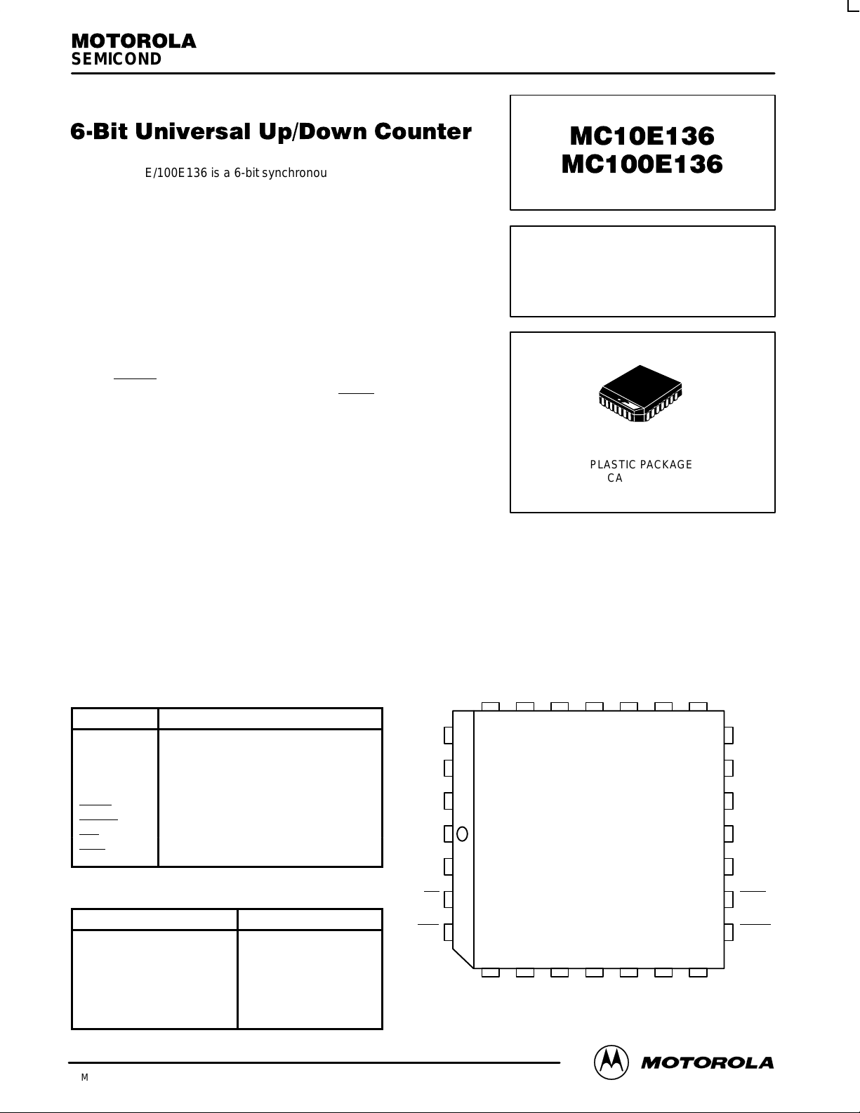
The MC10E/100E136 is a 6-bit synchronous, presettable, cascadable
universal counter. The device generates a look-ahead-carry output and
accepts a look-ahead-carry input. These two features allow for the
cacading of multiple E136’s for wider bit width counters that operate at
very nearly the same frequency as the stand alone counter.
• 550 MHz Count Frequency
• Fully Synchronous Up and Down Counting
• Internal 75 kΩ Input Pulldown Resistors
• Look-Ahead-Carry Input and Output
• Asynchronous Master Reset
• Extended 100E V
EE
Range of –4.2 V to –5.46 V
The CLOUT
output will pulse LOW for one clock cycle one count
before the E136 reaches terminal count. The COUT
output will pulse
LOW for one clock cycle when the counter reaches terminal count. For
more information on utilizing the look-ahead-carry features of the device
please refer to the applications section of this data sheet. The differential
COUT output facilitates the E136’s use in programmable divider and
self-stopping counter applications.
Unlike the H136 and other similar universal counter designs the E136
carry out and look-ahead-carry out signals are registered on chip. This
design alleviates the glitch problem seen on many counters where the carry out signals are merely gated. Because of this
architecture there are some minor functional differences between the E136 and H136 counters. The user, regardless of
familiarity with the H136, should read this data sheet carefully . Note specifically (see logic diagram) the operation of the carry out
outputs and the look-ahead-carry in input when utilizing the master reset.
When left open all of the input pins will be pulled LOW via an input pulldown resistor. The master reset is an asynchronous
signal which when asserted will force the Q outputs LOW.
The Q outputs need not be terminated for the E136 to function properly , in fact if these outputs will not be used in a system it is
recommended to save power and minimize noise that they be left open. This practice will minimize switching noise which can
reduce the maximum count frequency of the device or significantly reduce margins against other noise in the system.
PIN NAMES
Pin Function
D0 – D
5
Preset Data Inputs
Q0 – Q
5
Data Inputs
S1, S2 Mode Control Pins
MR Master Reset
CLK Clock Input
COUT, COUT Carry-Out Output (Active LOW)
CLOUT Look-Ahead-Carry Out (Active LOW)
CIN Carry-In Input (Active LOW)
CLIN Look-Ahead-Carry In Input (Active LOW)
FUNCTION TABLE (Expanded truth table on page 2–4)
S1
S2 CIN MR CLK Function
L
L
L
H
H
H
X
L
H
H
L
L
H
X
X
L
H
L
H
X
X
L
L
L
L
L
L
H
Z
Z
Z
Z
Z
Z
X
Preset Parallel Data
Increment (Count Up)
Hold Count
Decrement (Count Down)
Hold Count
Hold Count
Reset (Qn = LOW)
6-BIT UNIVERSAL
UP/DOWN COUNTER
FN SUFFIX
PLASTIC PACKAGE
CASE 776-02
MC10E136 MC100E136
MOTOROLA ECLinPS and ECLinPS Lite
DL140 — Rev 4
2–2
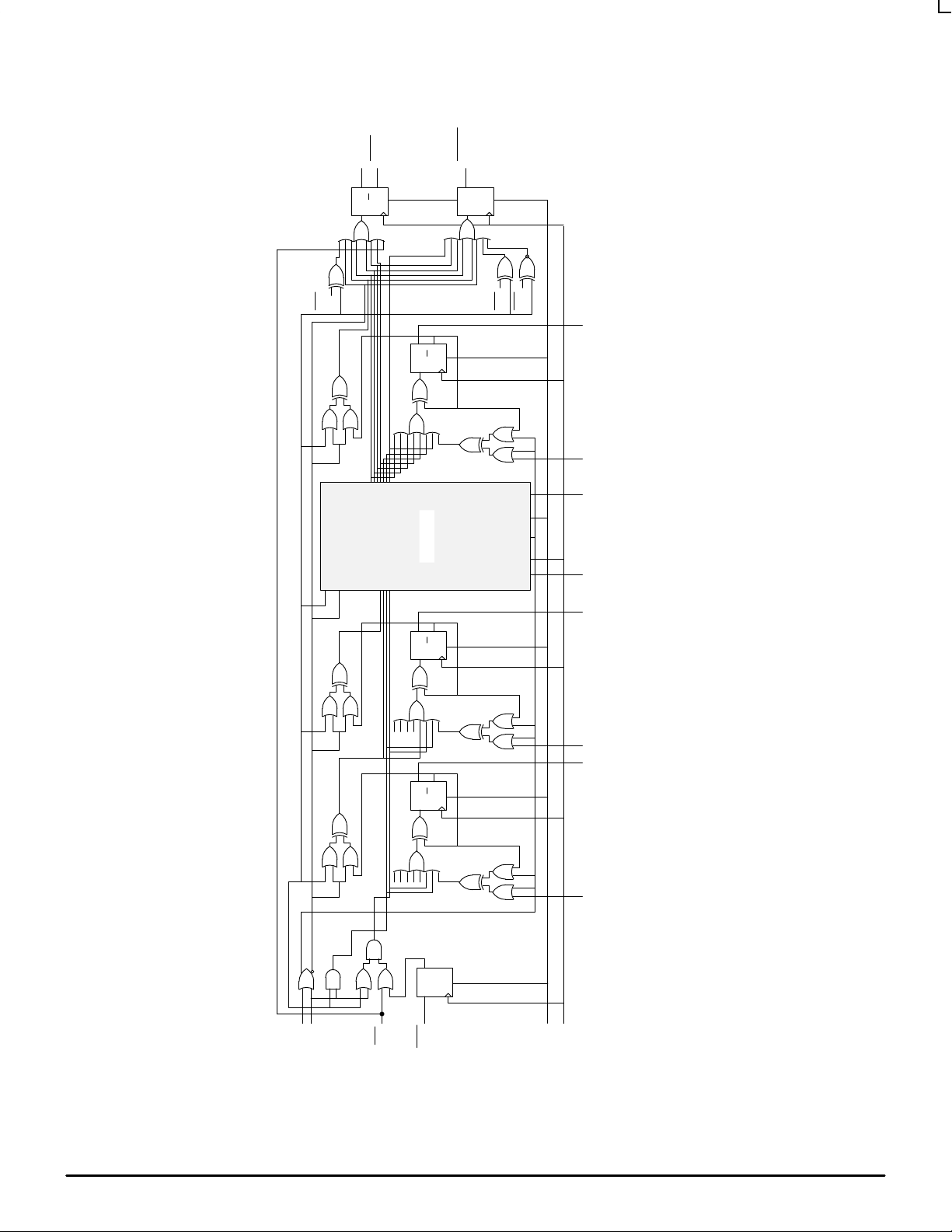
E136 Universal Up/Down Counter Logic Diagram
S1
S2
CIN
CLIN
MR
CLK
D Q
S
D Q
R
Q
D Q
R
Q
D Q
R
Q
D Q
S
Q
D Q
S
D0 Q0 D1 Q1 D2 – D4 Q2 – Q4 D5 Q5
COUT
QM0
QM1
QM0
COUT
CLOUT
Bits 2 – 4
Note that this diagram is provided for understanding of logic operation only. It should not be used for propagation delays as many gate functions
are achieved internally without incurring a full gate delay.
MC10E136 MC100E136
2–3 MOTOROLAECLinPS and ECLinPS Lite
DL140 — Rev 4
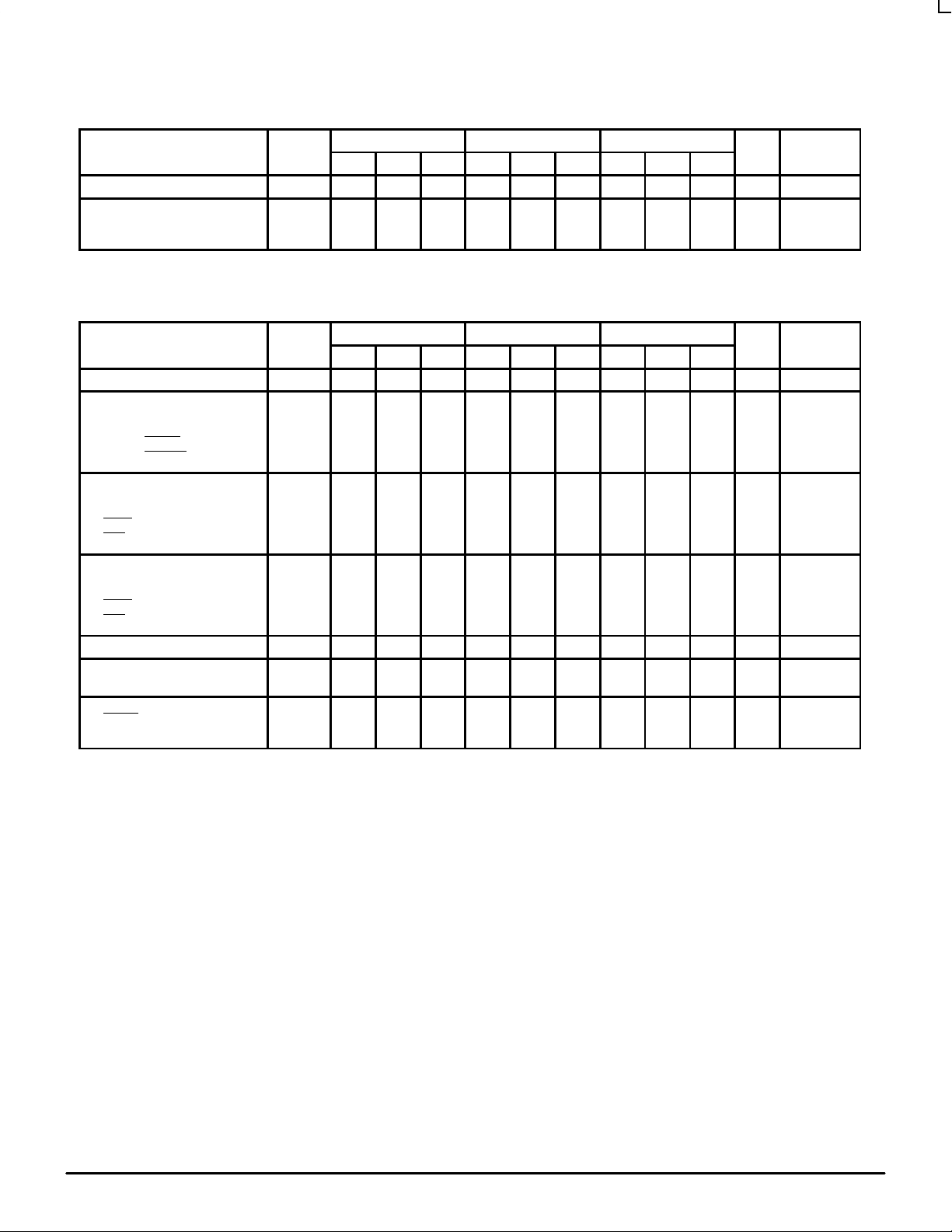
DC CHARACTERISTICS (V
EE
= VEE(min) to VEE(max); VCC = V
CCO
= GND)
0°C 25°C 85°C
Characteristic Symbol Min Typ Max Min Typ Max Min Typ Max Unit Condition
Input HIGH Current I
IH
— — 150 — — 150 — — 150 µA
Power Supply Current
10E
100E
I
EE
——125
125
150
150——
125
125
150
150——
125
140
150
170
mA
AC CHARACTERISTICS (V
EE
= VEE(min) to VEE(max); VCC = V
CCO
= GND)
0°C 25°C 85°C
Characteristic Symbol Min Typ Max Min Typ Max Min Typ Max Unit Condition
Maximum Count Frequency f
COUNT
550 650 — 550 650 — 550 650 — MHz
Propagation Delay to Output
CLK to Q
MR to Q
CLK to COUT
CLK to CLOUT
t
PLH
t
PHL
850
850
800
825
1150
1150
1150
1150
1450
1450
1300
1400
850
850
800
825
1150
1150
1150
1150
1450
1450
1300
1400
850
850
800
825
1150
1150
1150
1150
1450
1450
1300
1400
ps
Setup Time
S1, S2
D
CLIN
CIN
t
s
1000
800
150
800
650
400
0
400
—
—
—
—
1000
800
150
800
650
400
0
400
—
—
—
—
1000
800
150
800
650
400
0
400
—
—
—
—
ps
Hold Time
S1, S2
D
CLIN
CIN
t
h
150
150
300
150
–200
–250
0
–250
—
—
—
—
150
150
300
150
–200
–250
0
–250
—
—
—
—
150
150
300
150
–200
–250
0
–250
—
—
—
—
ps
Reset Recovery Time t
RR
1000 700 — 1000 700 — 1000 700 — ps
Minimum Pulse Width
CLK, MR
t
PW
700 400 — 700 400 — 700 400 —
ps
Rise/Fall Times
COUT
Other
t
r
t
f
275
300——
600
700
275
300——
600
700
275
300——
600
700
ps
20% - 80%
 Loading...