

Page 1
Symbol LS2208
Product Reference Guide
Page 2

Page 3

Symbol LS2208
Product Reference Guide
72E-58808-06
Revision A
May 2008
Page 4

ii Symbol LS2208 Product Reference Guide
© 2007-2008 by Motorola, Inc. All rights reserved.
No part of this publication may be reproduced or used in any form, or by any electrical or mechanical means,
without permission in writing from Motorola. This includes electronic or mechanical means, such as
photocopying, recording, or information storage and retrieval systems. The material in this manual is subject to
change without notice.
The software is provided strictly on an “as i s” basis. All sof twar e, including firmware, furnished to the user is on
a licensed basis. Motorola grants to the user a non-transferab le and non-exclusive license to use each
software or firmware program delivered hereunder (licensed program). Except as noted below, such license
may not be assigned, sublicensed, or otherwise transferred by the user without prior written consent of
Motorola. No right to copy a licensed program in whole or in part is granted, except as permitted unde r
copyright law. The user shall not modify, merge, or incorporate any form or portion of a licensed program with
other program material, create a derivative work from a licensed program, or use a licensed program in a
network without written permission from Motorola. The user agrees to maintain Motorola’s copyright notice on
the licensed programs delivered hereunder, and to include the same on any authorized copies it makes, in
whole or in part. The user agrees not to deco mpile, disassemble, decode, or reverse engineer any licensed
program delivered to the user or any portion thereof.
Motorola reserves the right to make changes to any software or product to improve reliability, function, or
design.
Motorola does not assume any product liability arising out of, or in connection with, the application or use of
any product, circuit, or application described herein.
No license is granted, either expressly or by implication, estoppel, or otherwise under any Motorola, Inc.,
intellectual property rights. An implied license only exists for equipment, circuits, and subsystems contained in
Motorola products.
MOTOROLA and the Stylized M Logo and Symbol and the Symbol logo are registered in the US Patent &
Trademark Office. Bluetooth is a registered trademark of Bluetooth SIG. Microsoft, Windows and ActiveSync
are either registered trademarks or trademarks of Microsoft Corporation. All other product or service names
are the property of their respective owners.
Motorola, Inc.
One Motorola Plaza
Holtsville, New York 11742-1300
http://www.symbol.com
Patents
This product is covered by one or more of the patents listed on the website: http://www.symbol.com/patents.
Warranty
For the complete Motorola hardware product warranty statement, go to: http://www.symbol.com/warranty.
Page 5

Revision History
Changes to the original manual are listed below:
Change Date Description
-01 Rev A 3/2003 Initial release.
-02 Rev A 10/2003 Updated with additional bar codes and various other changes.
-03 Rev A 1/2007 Updated service information, added parameter bar codes for Bookland ISBN, new
-04 Rev A 9/2007 Motorola rebranding, changed Set Length(s) for MSI parameter default to 4-55,
-05 Rev A 10/2007 Added bar codes for "Timeout Between Decodes" to User Preferences.
-06 Rev A 5/2008 Updated service information, removed IBM XT bar code and keyboard from
iii
UPC supplemental decode options, report software version, report MIMIC version,
report Synapse cable, COM port, prefix/suffix value.
changed RSS references to GS1 DataBar.
Keyboard Wedge chapter , add French Belgian country co des, added note regarding
Code ID and No Read, added Send Pause and Comma bar codes to ADF chapter.
Page 6

iv Symbol LS2208 Product Reference Guide
Page 7

Table of Contents
About This Guide
Introduction.................................................................................................................... xiii
Chapter Descriptions..................................................................................................... xiii
Notational Conventions.................................................................................................. xiv
Related Documents....................................................................................................... xv
Service Information........................................................................................................ xv
Chapter 1: Getting Started
Introduction ................................................................................................................... 1-1
Unpacking Your Scanner .............................................................................................. 1-2
Setting Up the Scanner ................................................................................................. 1-3
Installing the Interface Cable .................................................................................. 1-3
Connecting Power (if required) ............................................................................... 1-4
Configuring Your Scanner ....................................................................................... 1-4
Connecting a Synapse Cable Interface .................................................................. 1-5
Removing the Interface Cable ................................................................................ 1-5
Chapter 2: Scanning
Introduction ................................................................................................................... 2-1
Beeper Definitions ........................................................................................................ 2-2
LED Definitions ............................................................................................................. 2-3
Scanning in Hand-Held Mode ....................................................................................... 2-4
Aiming ........................................................................................................................... 2-5
Decode Zone ................................................................................................................ 2-6
Scanning in Hands-Free Mode ..................................................................................... 2-7
Assembling the Stand ............................................................................................. 2-7
Mounting the Stand (optional) ................................................................................. 2-8
Scanning in Hands-Free Mode ..................................................................................... 2-9
Scanning in the Hands-Free Mode ......................................................................... 2-9
Page 8

vi Symbol LS2208 Product Reference Guide
Chapter 3: Maintenance and Technical Specifications
Introduction ................................................................................................................... 3-1
Maintenance ................................................................................................................. 3-1
Troubleshooting ............................................................................................................ 3-2
Technical Specifications ............................................................................................... 3-4
Scanner Signal Descriptions ......................................................................................... 3-6
Chapter 4: User Preferences
Introduction ................................................................................................................... 4-1
Scanning Sequence Examples ..................................................................................... 4-1
Errors While Scanning .................................................................................................. 4-2
User Preferences Default Parameters .......................................................................... 4-2
User Preferences .......................................................................................................... 4-3
Set Default Parameter ............................................................................................ 4-3
Beeper Tone ........................................................................................................... 4-4
Beeper Volume ....................................................................................................... 4-5
Power Mode .................................................................................................................. 4-6
Laser On Time ........................................................................................................ 4-7
Beep After Good Decode ........................................................................................ 4-8
Timeout Between Decodes ........................................................................................... 4-9
Chapter 5: Keyboard Wedge Interface
Introduction ................................................................................................................... 5-1
Connecting a Keyboard Wedge Interface ..................................................................... 5-2
Keyboard Wedge Default Parameters .......................................................................... 5-3
Keyboard Wedge Host Types ....................................................................................... 5-4
Keyboard Wedge Host Types ................................................................................. 5-4
Keyboard Wedge Country Types (Country Codes) ................................................ 5-5
Ignore Unknown Characters ................................................................................... 5-7
Keystroke Delay ...................................................................................................... 5-8
Intra-Keystroke Delay ............................................................................................. 5-9
Alternate Numeric Keypad Emulation ..................................................................... 5-9
Caps Lock On ......................................................................................................... 5-10
Caps Lock Override ................................................................................................ 5-10
Convert Wedge Data .............................................................................................. 5-11
Function Key Mapping ............................................................................................ 5-12
FN1 Substitution ..................................................................................................... 5-13
Send Make and Break ............................................................................................ 5-13
Keyboard Maps ....................................................................................................... 5-14
ASCII Character Set ..................................................................................................... 5-16
Chapter 6: RS-232 Interface
Introduction ................................................................................................................... 6-1
Connecting an RS-232 Interface .................................................................................. 6-2
RS-232 Default Parameters .......................................................................................... 6-3
RS-232 Host Parameters .............................................................................................. 6-4
RS-232 Host Types ................................................................................................. 6-6
Page 9

Baud Rate ............................................................................................................... 6-8
Parity ....................................................................................................................... 6-10
Stop Bit Select ........................................................................................................ 6-12
Data Bits ................................................................................................................. 6-12
Check Receive Errors ............................................................................................. 6-13
Hardware Handshaking .......................................................................................... 6-14
Software Handshaking ............................................................................................ 6-16
Host Serial Response Time-out .............................................................................. 6-18
RTS Line State ........................................................................................................ 6-19
Beep on <BEL> ....................................................................................................... 6-19
Intercharacter Delay ................................................................................................ 6-20
Nixdorf Beep/LED Options ...................................................................................... 6-21
Ignore Unknown Characters ................................................................................... 6-21
ASCII Character Set ..................................................................................................... 6-22
Chapter 7: USB Interface
Introduction ................................................................................................................... 7-1
Connecting a USB Interface ......................................................................................... 7-1
USB Default Parameters .............................................................................................. 7-3
USB Host Parameters .................................................................................................. 7-4
USB Device Type .................................................................................................... 7-4
USB Country Keyboard Types (Country Codes) .................................................... 7-6
USB Keystroke Delay ............................................................................................. 7-9
USB CAPS Lock Override ...................................................................................... 7-10
USB Ignore Unknown Characters ........................................................................... 7-11
Emulate Keypad ...................................................................................................... 7-12
USB Keyboard FN 1 Substitution ............................................................................ 7-12
Function Key Mapping ............................................................................................ 7-13
Simulated Caps Lock .............................................................................................. 7-13
Convert Case .......................................................................................................... 7-14
ASCII Character Set ..................................................................................................... 7-15
Table of Contents vii
Chapter 8: IBM 468X/469X Interface
Introduction ................................................................................................................... 8-1
Connecting to an IBM 468X/469X Host ........................................................................ 8-2
IBM Default Parameters ............................................................................................... 8-3
IBM 468X/469X Host Parameters ................................................................................. 8-4
Port Address ........................................................................................................... 8-4
Convert Unknown to Code 39 ................................................................................. 8-5
Chapter 9: Wand Emulation Interface
Introduction ................................................................................................................... 9-1
Connecting Using Wand Emulation .............................................................................. 9-2
Wand Emulation Default Parameters ........................................................................... 9-3
Wand Emulation Host Parameters ............................................................................... 9-4
Wand Emulation Host Types .................................................................................. 9-4
Leading Margin (Quiet Zone) .................................................................................. 9-5
Page 10

viii Symbol LS2208 Product Reference Guide
Polarity .................................................................................................................... 9-6
Ignore Unknown Characters ................................................................................... 9-6
Convert All Bar Codes to Code 39 .......................................................................... 9-7
Convert Code 39 to Full ASCII ............................................................................... 9-7
Chapter 10: Undecoded Scanner Emulation Interface
Introduction ................................................................................................................... 10-1
Connecting Using Undecoded Scanner Emulation ....................................................... 10-2
Undecoded Scanner Emulation Default Parameters .................................................... 10-3
Undecoded Scanner Emulation Host ............................................................................ 10-4
Undecoded Scanner Emulation Host Parameters ........................................................ 10-5
Beep Style ............................................................................................................... 10-5
Parameter Pass-Through ........................................................................................ 10-6
Convert Newer Code Types .................................................................................... 10-7
Module Width .......................................................................................................... 10-7
Convert All Bar Codes to Code 39 .......................................................................... 10-8
Code 39 Full ASCII Conversion .............................................................................. 10-8
Transmission Timeout ............................................................................................. 10-9
Ignore Unknown Characters ................................................................................... 10-10
Leading Margin ....................................................................................................... 10-11
Check For Decode LED .......................................................................................... 10-12
Chapter 11: 123Scan
Introduction ................................................................................................................... 11-1
Communication With the 123Scan PC Based Configuration Tool ................................ 11-1
123Scan Parameter ...................................................................................................... 11-2
Chapter 12: Symbologies
Introduction ................................................................................................................... 12-1
Scanning Sequence Examples ..................................................................................... 12-1
Errors While Scanning .................................................................................................. 12-1
Symbology Default Parameters .................................................................................... 12-2
UPC/EAN ...................................................................................................................... 12-5
Enable/Disable UPC-A/UPC-E ............................................................................... 12-5
Enable/Disable UPC-E1 .......................................................................................... 12-6
Enable/Disable EAN-13/EAN-8 ............................................................................... 12-7
Enable/Disable Bookland EAN ............................................................................... 12-8
Decode UPC/EAN/JAN Supplementals .................................................................. 12-9
User-Programmable Supplementals ....................................................................... 12-12
UPC/EAN/JAN Supplemental Redundancy ............................................................ 12-12
Transmit UPC-A/UPC-E/UPC-E1 Check Digit ........................................................ 12-13
UPC-A Preamble .................................................................................................... 12-14
UPC-E Preamble .................................................................................................... 12-15
UPC-E1 Preamble .................................................................................................. 12-16
Convert UPC-E to UPC-A ....................................................................................... 12-17
Convert UPC-E1 to UPC-A ..................................................................................... 12-18
EAN-8/JAN-8 Extend .............................................................................................. 12-18
Page 11

Table of Contents ix
Bookland ISBN Format ........................................................................................... 12-19
UPC/EAN Security Level ........................................................................................ 12-20
UCC Coupon Extended Code ................................................................................. 12-21
Code 128 ...................................................................................................................... 12-22
Enable/Disable Code 128 ....................................................................................... 12-22
Enable/Disable UCC/EAN-128 ............................................................................... 12-22
Enable/Disable ISBT 128 ........................................................................................ 12-23
Code 39 ........................................................................................................................ 12-24
Enable/Disable Code 39 ......................................................................................... 12-24
Enable/Disable Trioptic Code 39 ............................................................................ 12-24
Convert Code 39 to Code 32 .................................................................................. 12-25
Code 32 Prefix ........................................................................................................ 12-25
Set Lengths for Code 39 ......................................................................................... 12-26
Code 39 Check Digit Verification ............................................................................ 12-27
Transmit Code 39 Check Digit ................................................................................ 12-27
Code 39 Full ASCII Conversion .............................................................................. 12-28
Code 39 Buffering (Scan & Store) .......................................................................... 12-29
Code 93 ........................................................................................................................ 12-32
Enable/Disable Code 93 ......................................................................................... 12-32
Set Lengths for Code 93 ......................................................................................... 12-33
Code 11 ........................................................................................................................ 12-34
Code 11 .................................................................................................................. 12-34
Set Lengths for Code 11 ......................................................................................... 12-35
Code 11 Check Digit Verification ............................................................................ 12-36
Transmit Code 11 Check Digits .............................................................................. 12-37
Interleaved 2 of 5 (ITF) ................................................................................................. 12-38
Enable/Disable Interleaved 2 of 5 ........................................................................... 12-38
Set Lengths for Interleaved 2 of 5 ........................................................................... 12-39
I 2 of 5 Check Digit Verification ............................................................................... 12-40
Transmit I 2 of 5 Check Digit ................................................................................... 12-41
Convert I 2 of 5 to EAN-13 ...................................................................................... 12-41
Discrete 2 of 5 (DTF) .................................................................................................... 12-42
Enable/Disable Discrete 2 of 5 ................................................................................ 12-42
Set Lengths for Discrete 2 of 5 ............................................................................... 12-43
Chinese 2 of 5 ............................................................................................................... 12-44
Enable/Disable Chinese 2 of 5 ................................................................................ 12-44
Codabar (NW - 7) ......................................................................................................... 12-45
Enable/Disable Codabar ......................................................................................... 12-45
Set Lengths for Codabar ......................................................................................... 12-46
CLSI Editing ............................................................................................................ 12-47
NOTIS Editing ......................................................................................................... 12-47
MSI ............................................................................................................................... 12-48
Enable/Disable MSI ................................................................................................ 12-48
Set Lengths for MSI ................................................................................................ 12-49
MSI Check Digits .................................................................................................... 12-50
Transmit MSI Check Digit(s) ................................................................................... 12-50
MSI Check Digit Algorithm ...................................................................................... 12-51
GS1 DataBar (Formerly RSS, Reduced Space Symbology) ........................................ 12-52
GS1 DataBar ........................................................................................................... 12-52
Convert GS1 DataBar to UPC/EAN ........................................................................ 12-53
Page 12

x Symbol LS2208 Product Reference Guide
Redundancy Level ........................................................................................................ 12-54
Redundancy Level 1 ............................................................................................... 12-54
Redundancy Level 2 ............................................................................................... 12-54
Redundancy Level 3 ............................................................................................... 12-55
Redundancy Level 4 ............................................................................................... 12-55
Security Level ............................................................................................................... 12-56
Security Level 0 ...................................................................................................... 12-56
Security Level 1 ...................................................................................................... 12-56
Security Level 2 ...................................................................................................... 12-56
Security Level 3 ...................................................................................................... 12-57
Bi-directional Redundancy ...................................................................................... 12-58
Intercharacter Gap Size .......................................................................................... 12-58
Report Version .............................................................................................................. 12-59
Report MIMIC Version .................................................................................................. 12-59
Report Synapse Cable .................................................................................................. 12-59
Chapter 13: Miscellaneous Scanner Options
Introduction ................................................................................................................... 13-1
Scanning Sequence Examples ..................................................................................... 13-2
Errors While Scanning .................................................................................................. 13-2
Miscellaneous Default Parameters ............................................................................... 13-2
Miscellaneous Scanner Parameters ............................................................................. 13-3
Transmit Code ID Character ................................................................................... 13-3
Prefix/Suffix Values ................................................................................................. 13-4
Scan Data Transmission Format ............................................................................ 13-4
FN1 Substitution Values ......................................................................................... 13-6
Transmit “No Read” Message ................................................................................. 13-6
Synapse Interface ................................................................................................... 13-7
Chapter 14: Advanced Data Formatting
Introduction ................................................................................................................... 14-1
Rules: Criteria Linked to Actions ................................................................................... 14-1
Using ADF Bar Codes .................................................................................................. 14-2
ADF Bar Code Menu Example ..................................................................................... 14-2
Rule 1: The Code 128 Scanning Rule .................................................................... 14-3
Rule 2: The UPC Scanning Rule ............................................................................ 14-3
Alternate Rule Sets ................................................................................................. 14-3
Rules Hierarchy (in Bar Codes) .............................................................................. 14-4
Default Rules .......................................................................................................... 14-5
Special Commands ....................................................................................................... 14-6
Pause Duration ....................................................................................................... 14-6
Begin New Rule ...................................................................................................... 14-6
Save Rule ............................................................................................................... 14-6
Erase ....................................................................................................................... 14-7
Quit Entering Rules ................................................................................................. 14-7
Disable Rule Set ..................................................................................................... 14-8
Criteria .......................................................................................................................... 14-9
Code Types ............................................................................................................. 14-9
Page 13

Code Lengths .......................................................................................................... 14-12
Message Containing A Specific Data String ........................................................... 14-17
Actions .......................................................................................................................... 14-20
Send Data ............................................................................................................... 14-20
Setup Field(s) .......................................................................................................... 14-23
Modify Data ............................................................................................................. 14-28
Pad Data with Spaces ............................................................................................. 14-29
Pad Data with Zeros ............................................................................................... 14-33
Beeps ...................................................................................................................... 14-37
Send Keystroke (Control Characters and Keyboard Characters) ........................... 14-38
Send Right Control Key .......................................................................................... 14-66
Send Graphic User Interface (GUI) Characters ...................................................... 14-67
Turn On/Off Rule Sets ............................................................................................ 14-72
Alphanumeric Keyboard ............................................................................................... 14-73
Appendix A: Standard Default Parameters
Table of Contents xi
Appendix B: Programming Reference
Symbol Code Identifiers ................................................................................................ B-1
AIM Code Identifiers ..................................................................................................... B-2
Appendix C: Sample Bar Codes
Code 39 ........................................................................................................................ C-1
UPC/EAN ...................................................................................................................... C-1
UPC-A, 100 % ......................................................................................................... C-1
EAN-13, 100 % ....................................................................................................... C-2
Code 128 ...................................................................................................................... C-2
Interleaved 2 of 5 .......................................................................................................... C-2
GS1 DataBar-14 ........................................................................................................... C-2
Appendix D: Numeric Bar Codes
Numeric Bar Codes ...................................................................................................... D-1
0, 1, 2 ...................................................................................................................... D-1
3, 4, 5, 6 .................................................................................................................. D-2
7, 8, 9 ...................................................................................................................... D-3
Cancel ........................................................................................................................... D-3
Glossary
Index
Tell Us What You Think...
Page 14

xii Symbol LS2208 Product Reference Guide
Page 15

About This Guide
Introduction
The Symbol LS2208 Product Reference Guide provides general instructions for setting up, operating, maintaining
and troubleshooting the Symbol LS2208.
Chapter Descriptions
Topics covered in this guide are as follows:
•
Chapter 1, Getting Started provides a product overview and unpacking instructions.
•
Chapter 2, Scanning describes part s of the scanne r , b eeper and LED definitions, and h ow to use the scanner
in hand-held and hands-free modes.
•
Chapter 3, Maintenance and Technical Specifications provides information on how to care for the scanner,
troubleshooting, and technical specifications.
•
Chapter 4, User Preferences provides programming bar codes for selecting user preference features for the
scanner.
•
Chapter 5, Keyboard Wedge Interface provides information for setting up the sc an ne r fo r Keyb o ar d Wedge
operation.
•
Chapter 6, RS-232 Interface provides information for setting up the scanner for RS-232 operation.
•
Chapter 7, USB Interface provides information for setting up the scanner for USB operation.
•
Chapter 8, IBM 468X/469X Interface provides information for setting up the scanner with IBM 468X/469X
POS systems.
•
Chapter 9, Wand Emulation Interface pr ovides information for setting up the scanne r fo r Wand emulation
operation.
•
Chapter 10, Undecoded Scanner Emulation Interface provides information for setting up the scanner for
Undecoded Scanner emulation operation.
•
Chapter 11, 123Scan (PC based scanner configuration tool) provides the bar code to scan to communicate
with the 123Scan program.
Page 16

xiv Symbol LS2208 Product Reference Guide
•
Chapter 12, Symbologies describes all symbology features and provides programming bar codes for
selecting these features for the scanner.
•
Chapter 13, Miscellaneous Scanner Option s includes features frequently used to customize how data
transmits to the host device.
•
Chapter 14, Advanced Data Formatting (ADF) describes how to customize scanned data befo re transmitting
to the host.
•
Appendix A, Standard Defaul t Parameters provides a table of all host devices and miscellaneous scanne r
defaults.
•
Appendix B, Programming Reference provides a table of AIM code identifiers, ASCII character conversions,
and keyboard maps.
•
Appendix C, Sample Bar Codes includes sample bar codes of various code types.
•
Appendix D, Numeric Bar Codes includes the numeric bar codes to scan for parameters requiring specific
numeric values.
Notational Conventions
The following conventions are used in this document:
•
Italics are used to highlight chapters and sections in this and related documents
•
Bold text is used to highlight parameter and bar code names
•
Bullets (•) indicate:
• Action items
• Lists of alternatives
• Lists of required steps that are not necessarily sequential
•
Sequential lists (e.g., those that describe step-by-s te p pr oc ed ur e s) ap pe a r as nu m be re d lists.
•
Throughout the programming bar code menus, asterisks (*) are used to denote default parameter settings.
* Indicates Default
NOTE This symbol indicates something of special interest or importance to the reader. Failure to read the note
will not result in physical harm to the reader, equipment or data.
*Baud Rate 9600
Feature/Option
CAUTION This symbol indicates that if this information is ignored, the possiblity of data or material damage may
occur.
WARNING! This symbol indicates that if this information is ignored the possibility that serious personal
injury may occur.
Page 17

Related Documents
The Symbol LS2208 Ser ies Quick Reference Gu ide, p/n 72-58807-xx, pro vides general information to help you get
started with the scanner. It includes basic set-up and operation instructions.
For the latest version of this guide and all guides, go to: http://www.symbol.com/manuals.
Service Information
If you have a problem with your equipment, contact Motorola Enterprise Mobility Support for your region. Contact
information is available at: http://www.symbol.com/contactsupport
When contacting Enterprise Mobility Support, please have the following information available:
•
Serial number of the unit
•
Model number or product name
•
Software type and version number.
About This Guide xv
.
Motorola responds to calls by E-mail, telephone or fax within the time limits set forth in support agreements.
If your problem cannot be solved by Motorola Enterprise Mobility Support, you may need to return your equipment
for servicing and will be given specific directions. Motorola is not responsible for any damages incurred during
shipment if the approved shipping container is not used. Shipping the units improperly can possibly void the
warranty.
If you purchased your Enterprise Mobility business product from a Motorola business partner, contact that business
partner for support.
Page 18

xvi Symbol LS2208 Product Reference Guide
Page 19
Chapter 1 Getting Started
Introduction
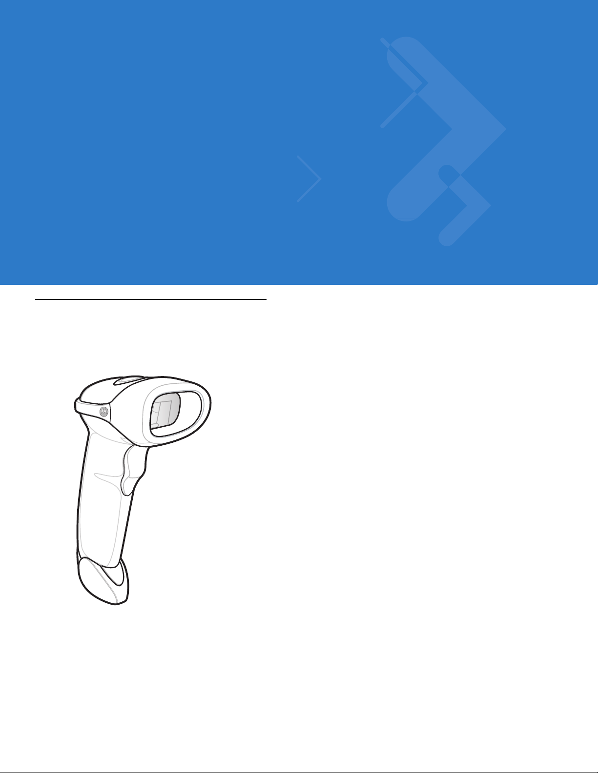
The Symbol LS2208 scanner combines excellent scanning performance and advanced ergonomics to provide the
best value in a lightweight laser scanner. Whether used as a hand-held scanner or in hands-free mode in a stand,
the scanner ensures comfort and ease of use for extended periods of time.
Figure 1-1
Symbol LS2208 Scanner
Page 20

1 - 2 Symbol LS2208 Product Reference Guide
The Symbol LS2208 scanner supports the following interfaces:
•
Stan dard RS-232 connection to a host. Scan bar code menus to set up pr oper communication o f the scanner
with the host.
•
Keyboard Wedge connection to a host. The host interprets scanned data as keystrokes.
•
International Keyboards supported: North America, German, French, French International, Spanish, Italian,
Swedish, British, Japanese, and Portuguese-Brazilian.
•
Wand Emulation connection to a ho st. The scanner connect s to a portable data terminal, a controller , or host
which collects the data as wand data and decodes it.
•
Undecoded Emulation connection to a host. The scanner connects to a portable data terminal, and a
controller which collects the data and interprets it for the host.
•
Connection to IBM 468X/469X hosts. Scan bar code menus to se t up proper communication of the scanner
with the IBM terminal.
•
USB connection to a host. The scanner autodetects a USB host and defaults to the HID keyboard interface
type. Scan programming bar codes to select other USB interface types.
•
International Keyboards supported (for Windows™ environment): North America, German, French, French
International, Spanish, Italian, Swedish, British, Portuguese-Brazilian, and Japanese.
•
Synapse capability. Enables connection to a wide variety of host systems using a Synapse and Synapse
adapter cable. The scanner autodetects Synapse.
•
Configuration via 123Scan.
Unpacking Your Scanner
Remove the scanner from its packing and inspect it for damage. If the scanner was damaged in transit, contact
Motorola Enterprise Mobility Support. See p age xv for contact information. KEEP THE PACKING. It is the
approved shipping container and should be used if you ever need to return your equipment for servicing.
Page 21
Setting Up the Scanner
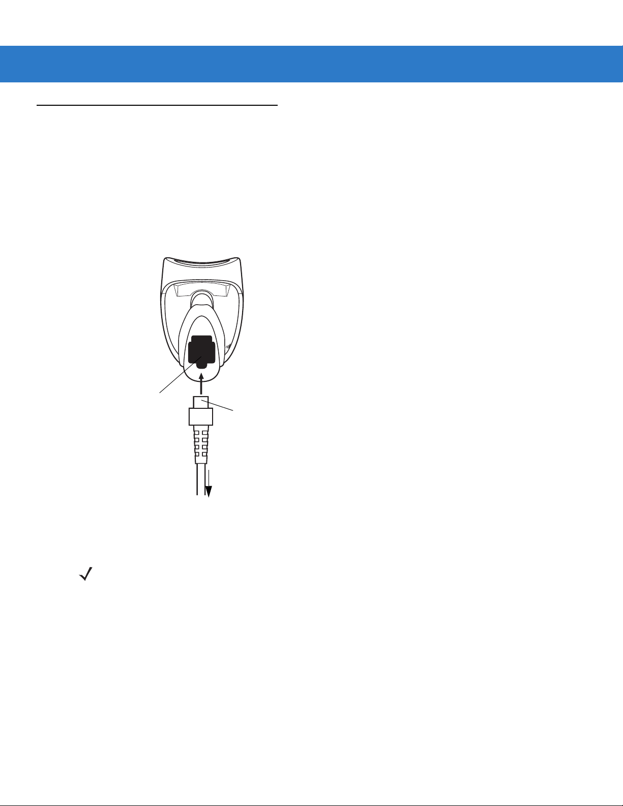
Installing the Interface Cable
1. Plug the interface cable modular connector into the cable interface port on the bottom of the scanner handle.
(See Figure 1-2.)
2. Gently tug the cable to ensure the connector is properly secured.
3. Connect the other end of the interface cable to the host (see the specific host chapter for information on host
connections).
Getting Started 1 - 3
Cable Interface Port
Figure 1-2
Installing the Cable
NOTE Different hosts require different cables. The connectors illustrated in each host chapter are examples only.
Interface Cable
Modular Connector
To host
Your connectors may be different than those illustrated, but the steps to connect the scanner are the
same.
Page 22

1 - 4 Symbol LS2208 Product Reference Guide
Connecting Power (if required)
If the host does not provide power to the scanner, use an external power connection to the scanner:
1. Connect the interface cable to the bottom of the scanner, as described in Installing the Interface Cable on page
1-3.
2. Connect the other end of the interface cable to the host (refer to the host manual to locate the correct port).
3. Plug the power supply into the power jack on the interface cable. Plug the other end of the power supp ly into
an AC outlet.
Configuring Your Scanner
To configure the scanner, use the bar codes included in this manual, or the 123Scan configuration program.
See Chapter 4, User Preferences for information about programming the scanner using bar code menus. See
Chapter 11, 123Scan to configure the scanner using this configuration program. 123Scan includes a help file.
The scanner supports RS-232, IBM 468X/469X, Keyboard Wedge, Wand Emulation, Undecoded Scanner
Emulation, USB, and Synapse to interface to a host system. Each host specific chapter describes how to set up
each of these connections.
Page 23
Getting Started 1 - 5
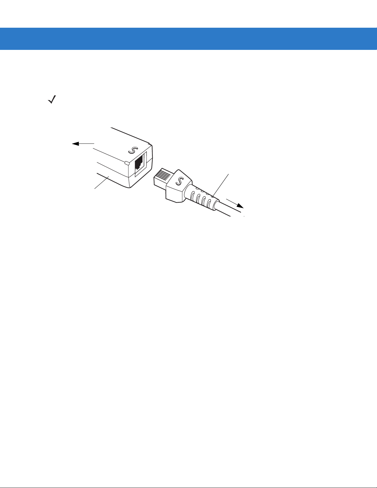
Connecting a Synapse Cable Interface
NOTE See the Synapse Interface Guide provided with the Synapse cable for detailed setup instructions.
Symbol’s Synapse Smart Cables enable interfacin g to a variety of hosts. The appropriate Synapse cable has the
built-in intelligence to detect the host to which it is connected.
To Host
Synapse Adapter Cable
Synapse Smart Cable
To Scanner
Figure 1-3
1. Plug the Synapse adapter cable (p/n 25-32463-xx) into the bottom of the scann er, as described in Installing the
Synapse Cable Connection
Interface Cable on page 1-3.
2. Align the ‘S’ on the Synapse adapter cable with the ‘S’ on the Synapse Smart Cable and plug the cable in.
3. Connect the other end of the Synapse Smart Cable to the host.
Removing the Interface Cable
To remove the interface cable:
1. Unplug the installed cable’s modular connector by depressing the connector clip with the tip of a screwdriver.
2. Carefully slide out the cable.
3. Follow the steps for Installing the Interface Cable on page 1-3 to connect a new cable.
Page 24

1 - 6 Symbol LS2208 Product Reference Guide
Page 25

Chapter 2 Scanning
Introduction
This chapter includes the techniques involved in scanning bar codes, beeper and LED definitions, and general
instructions and tips about scanning.
Scan Window
Trigger
LED
Figure 2-1
Scanner Parts
Page 26
2 - 2 Symbol LS2208 Product Reference Guide
Beeper Definitions
The scanner communicates by emitting different beeper sequences and patterns. Table 2-1 defines beep
sequences that occur during both normal scanning and while programming the scanner.
Table 2-1
Standard Use
Low/medium/high beep Power up.
Short high beep A bar code symbol was decoded (if decode beeper is
4 long low beeps A transmission error was detected in a scanned
5 low beeps Conversion or format error.
Lo/hi/lo beep ADF transmit error.
Hi/hi/hi/lo beep RS-232 receive error.
Parameter Menu Scanning
Short high beep Correct entry scanned or correct menu sequence
Lo/hi beep Input error, incorrect bar code or “Cancel” scanned,
Standard Beeper Definitions
Beeper Sequence Indication
enabled).
symbol. The data is ignored. This occurs if a unit is
not properly configured. Check option setting.
performed.
wrong entry, incorrect bar code programming
sequence; remain in program mode.
Hi/lo beep Keyboard parameter selected. Enter value using bar
code keypad.
Hi/lo/hi/lo beep Successful program exit with change in the
parameter setting.
Low/hi/low/hi beep Out of host parameter storage space. Scan
Default Parameter on page 4-3
Code 39 Buffering
Hi/lo beep New Code 39 data was entered into the buffer.
3 Beeps - long high beep Code 39 buffer is full.
Lo/hi/lo beep The Code 39 buffer was erased or there was an
attempt to clear or transmit an empty buffer.
Lo/hi beep A successful transmission of buffered data.
.
Set
Page 27
Scanning 2 - 3
Table 2-1
Host Specific
Standard Beepe r Definitions (Continued)
USB only
4 short high beeps Scanner has not completed initialization. W ait several
Scanner gives a power-up beep after scanning a
USB Device Type.
This power-up beep occurs more than once. The USB bus may put the scanner in a state where
RS-232 only
1 short high beep A <BEL> character is received and Beep on <BEL> is
LED Definitions
Beeper Sequence Indication
seconds and scan again.
Communication with the bus must be established
before the scanner can operate at the highest power
level.
power to the scanner is cycled on and off more than
once. This is normal and usually happens when the
PC cold boots.
enabled.
In addition to beeper sequences, the scanner communicates using a two-color LED display. Tab le 2-2 defines LED
colors that display during scanning.
Table 2-2
Off No power is applied to the scanner, or the scanner is on and ready to scan.
Green A bar code was successfully decoded.
Red A data transmission error or scanner malfunction occurred.
Standard LED Definitions
LED Indication
Page 28

2 - 4 Symbol LS2208 Product Reference Guide
Scanning in Hand-Held Mode
Install and program the scanner. See each host chapter and Chapter 4, User Preferences, Chapter 12,
Symbologies, Chapter 13, Miscellaneous Scanner Options, and Chapter 14, Advanced Data Formatting for
programming instructions. For assistance, contact your local supplier or Motorola Enterprise Mobility Support.
Figure 2-2
1. Ensure all connections are secure. See the host chapter for your host.
2. Aim the scanner at the bar code. Press the trigger.
3. Ensure the scan line crosses every bar and space of the symbol.
4. Upon successful decode, the scanner beeps and the LED turns green. For more information on beeper and
LED definitions, see Table 2-1 and Table 2-2.
Scanning in Hand-Held Mode
RIGHT
012345
WRONG
012345
Page 29
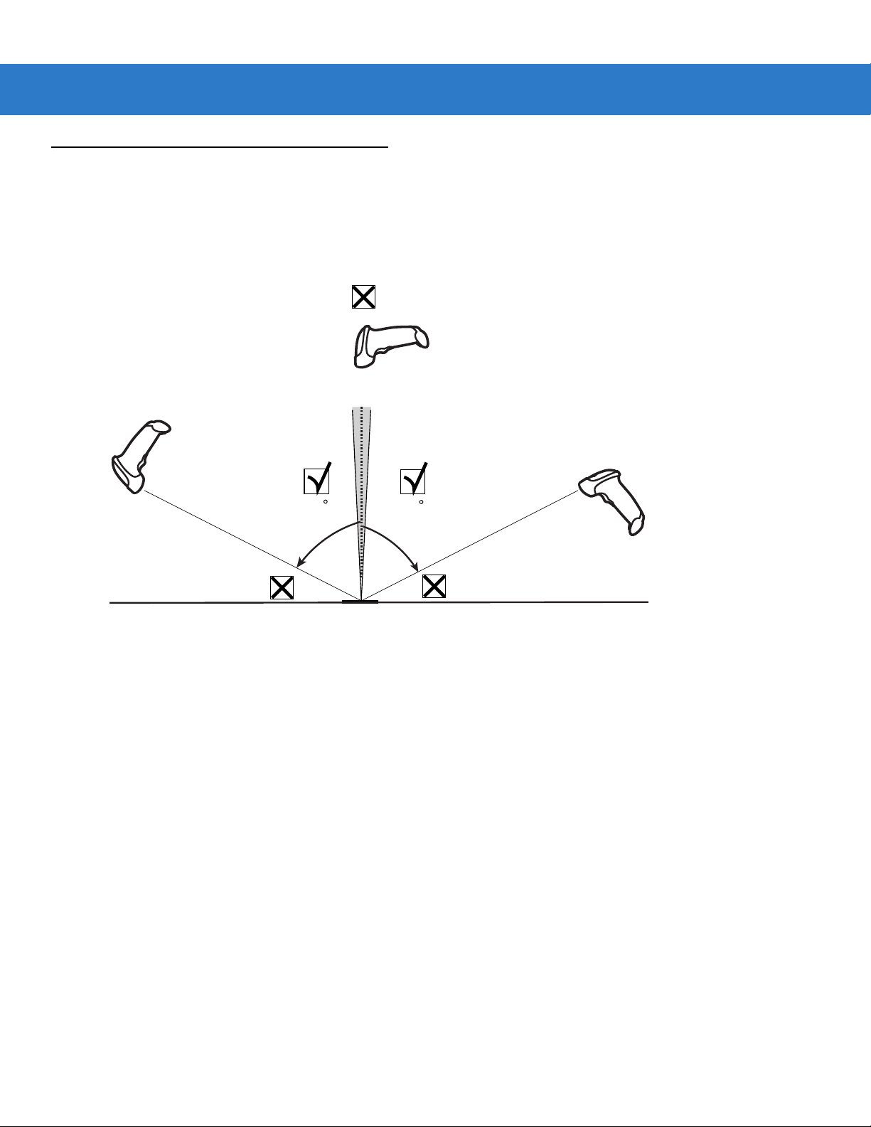
Aiming
Do not hold the scanner directly over the bar code. Laser light reflecting directly back into the scanner from the bar
code is known as specular reflection. This specular reflection can make decoding difficult.
You can tilt the scanner up to 55° forward or back and achieve a successful decode (Figure 2-3). Simple practice
quickly shows what tolerances to work within.
Scanning 2 - 5
Figure 2-3
65
Maximum Tilt Angles and Dead Zone
65
Page 30
2 - 6 Symbol LS2208 Product Reference Guide
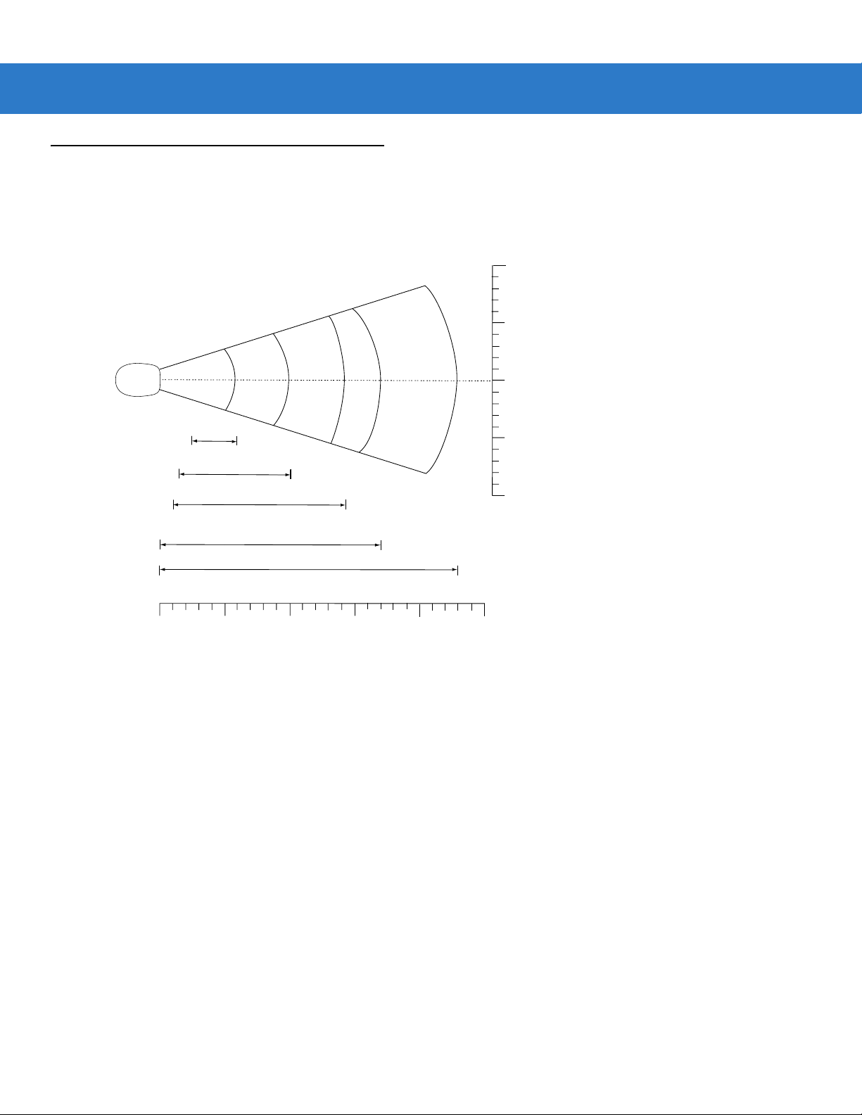
Decode Zone
Note: Typical performance at 73˚ F (23˚ C) on
high quality symbols in normal room light.
LS 2208
5 mil
2.5"
1.5"
1.0"
0
6"
7.5 mil
10 mil
100% UPC
*
cm
0
in.
0
5
12.7
10
25.4
Depth of Field
*Minimum distance determined by symbol length and scan angle
10.0"
20 mil
14.5"
15
38.1
17.0"
20
50.8
23.0"
25
63.5
in. cm
10 25.4
5 12.7
0 0
5 12.7
10 25.4
W
i
d
t
h
o
f
F
i
e
l
d
Figure 2-4
Symbol LS2208 Decode Zone
Page 31

Scanning in Hands-Free Mode
The Symbol LS2208 Intellistand adds greater flexibility to scanning operation. See Assembling the Stand,
Mounting the St and (optional), and Scanning in the Hands-Free Mode for more information about hands-free
scanning.
Assembling the Stand
One piece scanner
“cup” with flexible neck.
1.
Unscrew the wingnut
from the bottom of the
one piece scanner “cup”.
Scanning 2 - 7
Figure 2-5
NOTE Before tightening the wingnut under the base, ensure that the flat areas on the flexible neck fit securely in
Flat areas
Stand base
Wingnut
Assembling the Stand
the grooves in the base.
2. Fit the bottom of the neck
piece into the opening on
the top of the stand base.
3. Tighten the wingn ut
underneath the base to
secure the cup and neck
piece to the base (see
the note below).
4. Bend the neck to the
desired position for
scanning.
Page 32

2 - 8 Symbol LS2208 Product Reference Guide
Mounting the Stand (optional)
You can attach the base of the scanner’s stand to a fl at surface using two screws or double-sided tape (not
provided).
Two screw-mount holes
Double-sided tape areas
(3 places)
dimensions = 1” x 2”)
Figure 2-6
Mounting the Stand
Screw Mount
1. Position the assembled base on a flat surface.
2. Screw one #10 wood screw into each screw-mount hole until the base of the sta nd is secure (see Figure 2-6).
Tape Mount
1. Peel the paper liner off one side of each piece of tape and place the sticky surface over each of the three
rectangular tape holders.
2. Peel the paper liner off the exposed sides of each piece of tape and press the stand on a flat surface until it is
secure (see Figure 2-6).
Page 33

Scanning in Hands-Free Mode
The optional Intellistand adds greater flexibility to scanning operation.
Scanning in the Hands-Free Mode
When the scanner is seated in the stand’s “cup”, the scanner’s built-in sensor places the scanner in hands-free
mode. When you remove the scanner from the stand it operates in its normal hand-held mode.
Scanning 2 - 9
Scanner
Holder (Front)
Figure 2-7
Intellistand operation:
1. Ensure all cable connections are secure.
2. Insert the scanner in the optional Intellistand by placing the front of the scanner into the stand’s “cup” (see
Figure 2-7).
3. To scan a bar code, present the bar code and ensure the scan line crosses every bar and space of the symbol.
4. Upon successful decode, the scanner beeps and the LED turns green.
Inserting and Using the Scanner in the Stand
Page 34

2 - 10 Symbol LS2208 Product Reference Guide
Page 35

Chapter 3 Maintenance and Technical
Specifications
Introduction
This chapter includes suggested scanner maintenance, troubleshooting, technical specifications, and signal
descriptions (pinouts).
Maintenance
Cleaning the exit window is the only maintenance required. A dirty window can affect scanning accuracy.
•
Do not allow any abrasive material to touch the window
•
Remove any dirt particles with a damp cloth
•
Wipe the window using a tissue moistened with ammonia/water
•
Do not spray water or other cleaning liquids directly into the window.
Page 36

3 - 2 Symbol LS2208 Product Reference Guide
Troubleshooting
Table 3-1
Nothing happens when you follow
the operating instructions, or the
scanner displays erratic behavior
(laser does not come on, scanner
emits frequent beeps).
Laser comes on, but symbol does
not decode.
Symbol is decoded, but not
transmitted to the host.
Troubleshooting
Problem Possible Causes Possible Solutions
No power to the scanner. Check the system power. Ensure the power
supply is connected if your configuration
requires a power supply.
Interface/power cables are
loose.
Scanner is not programmed
for the correct bar code type.
Bar code symbol is
unreadable.
Distance between scanner
and bar code is incorrect.
Scanner is not programmed
for the correct host type.
Check for loose cable connections.
Be sure the scanner is programmed to read
the type of bar code you are scanning.
Check the symbol to make sure it is not
defaced. Try scanning test symbols of the
same bar code type.
Move the scanner closer to or further from
the bar code.
Scan the appropriate host type bar code.
Page 37

Maintenance and Technical Specifications 3 - 3
Table 3-1
Troubleshooting (continued)
Problem Possible Causes Possible Solutions
Scanned data is incorrectly
displayed on the host.
NOTE If after performing these checks the symbol still does not scan, contact your distributor or Motorola
Enterprise Mobility Support. See page xv for contact information.
Scanner is not programmed to
work with the host. Check
scanner host type parameters
or editing options.
Be sure proper host is selected. (See the
host chapter for your scanner.)
For RS-232, ensure the scanner’s
communication parameters match the host’ s
settings.
For a USB HID keyboard or a keyboard
wedge configuration, ensure the system is
programmed for the correct keyboard type
and language, and the CAPS LOCK key is in
the correct state.
Be sure editing options (e.g., ADF, UPC-E to
UPC-A Conversion) are properly
programmed.
Page 38

3 - 4 Symbol LS2208 Product Reference Guide
Technical Specifications
Table 3-2
Power Requirements Decoded: 5 VDC + / - 10% @ approximately 200mA (nominal)
Stand-By Current 500mA (max)
Power Source Depending on host:
Decode Capability Decoded:
Beeper Operation User-selectable: Enable, Disable
Beeper Volume User-selectable: three levels
Beeper Tone User-selectable: three tones
Technical Specifications
Item Description
•
Host powered
•
External power supply
•
Battery box:
Converts a 9 Volt battery to a 5 Volt battery
UPC/EAN, UPC/EAN with supplementals, UCC/EAN, JAN 8 & 13, 128, Code 39,
Code 39 Full ASCII, Code 39 Trioptic, Codabar (NW7), Interleaved 2 of 5,
Discrete 2 of 5, Code 128, Code 93, MSI, Code 11, UCC/EAN, GS1 DataBar,
Code 32, Coupon Code, Bookland EAN, IATA.
Scan Repetition Rate 100 ± 5 scans/second
Yaw Tolerance ± 10° from nominal
Pitch Tolerance ± 65° from nominal
Roll Tolerance ± 60° from nominal
Print Contrast Minimum 25% minimum reflectance differential, measured at 650 nm.
Ambient Light Immunity
Indoor:
Outdoor:
Durability 5 ft (1.5 m) drops to concrete
Operating Temperature 32° to 120° F (0° to 50° C)
Storage Temperature -40° to 140° F (-40° to 60° C)
Humidity 5% to 95% (non-condensing)
Weight (without cable) 5.15 oz. (146 g)
Dimensions:
Height
Width
Depth
450 Ft Candles (4,842 Lux) (indoor)
10,000 Ft Candles (107,600 Lux) (outdoor)
6.0 in. (15.2 cm)
2.5in. (6.3 cm)
3.34 in. (8.4 cm)
Page 39

Maintenance and Technical Specifications 3 - 5
Table 3-2
Laser 650nm laser diode
Laser Classifications IEC 825-1 Class 2
ESD 15 kV area discharge
Minimum Element Width 5 mil (0.127 mm)
Interfaces Supported Decoded:
Electrical Safety Certified Pending to UL1950, CSA C22.2 No.950. EN60950/IC950
Input Transient Protection IEC 1000-4-(2,3,4,5,6,11)
EMI FCC Part 15 Class B, ICES-003 Class B European Union EMC Directive,
Technical Specifications (continued)
Item Description
8 kV contact discharge
RS-232, Keyboard Wedge, Wand Emulation, Undecoded Scanner Emulation,
IBM 468X/469X, USB, Synapse
Australian SMA, Taiwan EMC, Japan VCCI/MITI/Dentori
Page 40

3 - 6 Symbol LS2208 Product Reference Guide
Scanner Signal Descriptions
Bottom of Scanner
Cable Interface Port
PIN 10
Interface Cable
Modular Connector
Figure 3-1
Scanner Cable Pinouts
PIN 1
Page 41

Maintenance and Technical Specifications 3 - 7
The signal descriptions in Table 3-3 apply to the connector on the scanner and are for reference only.
Table 3-3
Pin IBM Synapse RS-232
1 Reserved SynClock Reserved Reserved Reserved Jump to Pin 6
2 Power Power Power Power Power Power
3 Ground Ground Ground Ground Ground Ground
4 IBM_A(+) Reserved TxD KeyClock DBP Reserved
5 Reserved Reserved RxD TermData CTS D +
6 IBM_B(-) SynData RTS KeyData RTS Jump to Pin 1
7 Reserved Reserved CTS TermClock Reserved D 8 Reserved Reserved Reserved Reserved Reserved Reserved
9 Reserved Reserved Reserved Reserved Reserved Reserved
10 Reserved Reserved Reserved Reserved Reserved Reserved
Scanner Signal Pin-outs
Symbol LS2208
Keyboard
Wedge
Wand USB
Page 42

3 - 8 Symbol LS2208 Product Reference Guide
Page 43

Chapter 4 User Preferences
Introduction
You can program the Symbol LS2208 scanner to perform various functions, or activate different features. This
chapter describes each user preference feature and provides programming bar codes for selecting these features
for the Symbol LS2208 scanner.
The Symbol LS2208 ships with the settings shown in the User Preferences Default Table on page 4-2 (also see
Appendix A, Standard Defaul t Parameters for all host device and miscellaneous scanner defaults). If the default
values suit requirements, programming is not necessary.
Set feature values by scanning single bar codes or short bar code sequences. The settings are stored in
non-volatile memory and are preserved even when the scanner is powered down.
If you are not using a Synapse or USB cable you must select a host type (see each host chapter for specific host
information). After the power-up beeps sound, select a host type. You only need to this once, upon the first
power-up when connecting to a new host.
To return all features to their default values, scan Set All Defaults on page 4-3. Throughout the programming bar
code menus, asterisks (
*) indicate default values.
* Indicates Default
Scanning Sequence Examples
In most cases, scanning one bar code sets the parameter value. For example, to set the beeper tone to high, scan
the High Frequency (beeper tone) bar code under Beeper Tone on page 4-4. The scanner issues a fast warble
beep and the LED turns green, signifying a succe ssf ul paramete r en tr y.
Other parameters, such as specifying Serial Response Time-Out or setting Data Transmission Formats, require
scanning several bar codes. See Laser On Time on page 4-7 and Scan Data Transmission Format on page 13-4
for descriptions of this procedure.
*High Frequency
Feature/Option
Page 44

4 - 2 Symbol LS2208 Product Reference Guide
Errors While Scanning
Unless otherwise specified, to correct an error during a scanning sequence, just re-scan the correct parameter.
User Preferences Default Parameters
Table 4-1 lists the defaults for user preferences parameter s. To change any option, scan the appropriate bar
code(s) provided in the User Preferences section beginning on page 4-3.
NOTE See Appendix A, Standard Default Parameters for all user preferences, hosts, symbologies, and
miscellaneous default parameters.
Table 4-1
User Preferences
Set Default Parameter All Defaults
Beeper Tone Medium
Beeper Volume High
Power Mode Continuous On
Laser On Time 3.0 Sec
Beep After Good Decode Enable
Timeout Between Decodes
Time-out Between Same Symbol 0.6 sec
Time-out Between Different Symbols 0.2 sec
User Preferences Default Table
Parameter Default
Page
Number
4-3
4-4
4-5
4-6
4-7
4-8
4-9
4-9
Page 45

User Preferences
Set Default Parameter
Scanning this bar code returns all parameters to the default values listed in Table A-1 on page A-1.
User Preferences 4 - 3
Set All Defaults
Page 46

4 - 4 Symbol LS2208 Product Reference Guide
Beeper Tone
To select a decode beep frequency (tone), scan the Low Frequency, Medium Frequency, or High Frequency bar
code.
Low Frequency
*Medium Frequency
(Optimum Settings)
High Frequency
Page 47

Beeper Volume
To select a beeper volume, scan the Low Volume, Medium Volume, or High Volume bar code.
Low Volume
Medium Volume
User Preferences 4 - 5
*High Volume
Page 48

4 - 6 Symbol LS2208 Product Reference Guide
Power Mode
This parameter determines whether or not power remains on after a decode attempt. When in reduced power
mode, the scanner enters into a low power consumption mode to preserve battery life after each decode attempt.
When in continuous power m od e , p ow er r em a ins on a fter ea ch decode attempt.
*Continuous On
Reduced Power Mode
Page 49

User Preferences 4 - 7
Laser On Time
This parameter sets the maximum time that decode processing continues during a scan attempt. It is
programmable in 0.1 second increments from 0.5 to 9.9 seconds. The default Laser On Time is 3.0 seconds.
To set a Laser On Time, scan the bar code below. Next, scan two numeric bar codes beginning on page D-1 in
Appendix D, Numeric Bar Codes that correspond to the desired on time. Include a leading zero for single digit
numbers. For example, to set an On Time of 0.5 seconds, scan the bar code below, then scan the “0” and “5” bar
codes. To correct an error or change a selection, scan Cancel on page D-3.
Laser On Time
Page 50

4 - 8 Symbol LS2208 Product Reference Guide
Beep After Good Decode
Scan a bar code below to select whether or not the scanner beeps af ter a good decode. If you select Do Not Beep
After Good Decode, the beeper still operates during parameter menu scanning and indicates error conditions.
*Beep After Good Decode
(Enable)
Do Not Beep After Good Decode
(Disable)
Page 51

Timeout Between Decodes
Timeout Between Decodes, Same Symbol
This parameter sets the minimum time between decodes of the same symbol. It is programmable in 0.1-second
increments from 0.0 to 9.9 seconds. Setting this above 0.4 seconds is recommended. The default for this
parameter is 0.6 seconds.
Scan the bar code below to select a new timeout. Next, scan two numeric bar codes beginning in Numeric Bar
Codes on page D-1 that correspond to the desired timeout. Include a leading zero for single digit numbers. For
example, to set a timeout of 0.5 seconds, scan the bar code below, then scan the “0 ” a nd “5” ba r co des. If a n err or
occurs, or to change the selection, scan Cancel on page D-3.
User Preferences 4 - 9
Timeout Between Same Symbol
Timeout Between Decodes, Different Symbol
This parameter sets the minimum time between decodes of different symbols. It is programmable in 0.1- second
increments from 0.0 to 9.9 seconds. The default for this parameter is 0.2 seconds.
Scan the bar code below to select a new timeout. Next, scan two numeric bar codes beginning in Numeric Bar
Codes on page D-1 that correspond to the desired timeout. Include a leading zero for single digit numbers. For
example, to set a timeout of 0.5 seconds, scan the bar code below, then scan the “0 ” a nd “5” ba r co des. If a n err or
occurs, or to change the selection, scan Cancel on page D-3.
Timeout Between Different Symbol
Page 52

4 - 10 Symbol LS2208 Product Reference Guide
Page 53

Chapter 5 Keyboard Wedge Interface
Introduction
This chapter covers Keyboard Wedge interface information for setting up the scanner. Use this interface type to
attach the scanner between the keyboard and host computer . The scanner translates the bar code data into
keystrokes. The host computer accepts the keystrokes as if they originate from the keyboard.
This mode of operation allows adding bar code reading functionality to a system designed for manual keyboard
input. In this mode the keyboard keystrokes are simply passed through.
Throughout the programming bar code menus, aste risks (
* Indicates Default
*North American
*) indicate default values.
Feature/Option
Page 54

5 - 2 Symbol LS2208 Product Reference Guide
Connecting a Keyboard Wedge Interface
Male DIN Keyboard Connector to Host Connector to Host
Power supply
(if needed)
Y-cable
Figure 5-1
Keyboard Wedge Connection with Y-cable
To connect the Keyboard Wedge Y-cable:
1. Switch off the host and unplug the keyboard connector.
2. Attach the modular connector of the Y-cable to the cable interface port on the scanner. (See Installing the
Interface Cable on page 1-3.)
3. Connect the round male DIN host connector of the Y-cable to the keyboard port on the host device.
4. Connect the round female DIN keyboard connector of the Y-cable to the keyboard.
5. If needed, attach the optional power supply to the connector in the middle of the Y-cable.
6. Ensure that all connections are secure.
7. Switch on the host system.
8. Scan the appropriate bar codes in this chapte r to configure the scanner.
Page 55

Keyboard Wedge Default Parameters
Table 5-1 lists the defaults for Keyboard Wedge host parameters. To change any option, scan the appropriate bar
code(s) provided in the Keyboard Wedge Host Parameters section beginning on page 5-4.
NOTE See Appendix A, Standard Default Parameters for all user preferences, hosts, symbologies, and
miscellaneous default parameters.
Keyboard Wedge Interface 5 - 3
Table 5-1
Keyboard Wedge Host Parameters
Keyboard Wedge Host Type
Country Types (Country Codes) North American
Ignore Unknown Characters Transmit
Keystroke Delay No Delay
Intra-Keystroke Delay Disable
Alternate Numeric Keypad Emulation Disable
Caps Lock On Disable
Caps Lock Override Disable
Convert Wedge Data No Convert
Function Key Mapping Disable
FN1 Substitution Disable
Keyboard Wedge Host Default Table
Parameter Default
IBM PC/AT& IBM PC Compatibles
Page
Number
1
5-4
5-5
5-7
5-8
5-9
5-9
5-10
5-10
5-11
5-12
5-13
Send and Make Break Send
1
User selection is required to configure this interface and this is the most common selection.
5-13
Page 56

5 - 4 Symbol LS2208 Product Reference Guide
Keyboard Wedge Host Types
Keyboard Wedge Host Types
Select the keyboard wedge host by scanning one of the bar codes below.
IBM PC/A T & IBM PC Compatibles
IBM PS/2 (Model 30)
IBM AT NOTEBOOK
NCR 7052
1
NOTE User selection is required to configure this interfac e and this is the most common selection.
Page 57

Keyboard Wedge Interface 5 - 5
Keyboard Wedge Country Types (Country Codes)
Scan the bar code corresponding to the keyboard type. If your particular keyboard type is not listed, see Alternate
Numeric Keypad Emulation on page 5-9.
*North American
German Windows
French Windows
French Canadian Windows 95/98
French Canadian Windows XP/2000
French Belgian Windows
Page 58

5 - 6 Symbol LS2208 Product Reference Guide
Keyboard Wedge Country Types (Country Codes) (continued)
Spanish Windows
Italian Windows
Swedish Windows
UK English Windows
Japanese Windows
Portuguese-Brazilian Windows
Page 59

Keyboard Wedge Interface 5 - 7
Ignore Unknown Characters
Unknown characters are characters the host does not recognize. Select Send Bar Codes With Unkno wn
Characters to send all bar code data except for unknown characters. The scanner sounds no error beeps.
Select Do Not Send Bar Codes With Unknown Characters to send bar code data up to the first unknown
character. The scanner sounds an error beep.
*Send Bar Codes with Unknown Characters
(Transmit)
Do Not Send Bar Codes with Unknown Characters
Page 60

5 - 8 Symbol LS2208 Product Reference Guide
Keystroke Delay
This is the delay in milliseconds between emulated keystrokes. Scan a bar code below to increase the delay when
hosts require a slower transmission of data.
*No Delay
Medium Delay (20 msec)
Long Delay (40 msec)
Page 61

Keyboard Wedge Interface 5 - 9
Intra-Keystroke Delay
Enable this to insert an additional delay between each emulated key depression and release. This sets the
Keystroke Delay parameter to a minimum of 5 msec as well.
Enable
*Disable
Alternate Numeric Keypad Emulation
This allows emulation of most other country keyboard types not listed in Keyboard W ed ge Co untry Types (Country
Codes) on page 5-5 in a Microsoft operating system environment.
Enable Alternate Numeric Keypad
*Disable Alternate Numeric Keypad
Page 62

5 - 10 Symbol LS2208 Product Reference Guide
Caps Lock On
When enabled, the scanner emulates keystrokes as if the Caps Lock key is always pressed.
Enable Caps Lock On
*Disable Caps Lock On
Caps Lock Override
When enabled, on A T or AT Notebook hosts, the keyboard ignores the state of the Caps Lock key. Therefore, an ‘A ’
in the bar code transmits as an ‘A’ regardless of the state of the keyboard’s Caps Lock key.
Enable Caps Lock Override
*Disable Caps Lock Override
NOTE If both Caps Lock On and Caps Lock Override are enabled, Caps Lock Override takes precedence.
Page 63

Convert Wedge Data
Enable this to convert all bar code data to the selected case.
Convert to Upper Case
Keyboard Wedge Interface 5 - 11
Convert to Lower Case
*No Convert
Page 64

5 - 12 Symbol LS2208 Product Reference Guide
Function Key Mapping
ASCII values under 32 are normally sent as control key sequences (see Table 5-2 on page 5-16). Enable this to
send the keys in bold in place of the standard key mapping. Table entries that do not have a bold entry remain the
same whether or not you enabled this parameter.
Enable
*Disable
Page 65

Keyboard Wedge Interface 5 - 13
FN1 Substitution
Enable this to allow replacing any FN1 characters in an EAN128 bar code with a user-sele cted keystroke (see FN1
Substitution Values on page 13-6).
Enable
*Disable
Send Make and Break
When enabled, the scan codes for releasing a key are not sent.
*Send Make and Break Scan Codes
Send Make Scan Code Only
Page 66

5 - 14 Symbol LS2208 Product Reference Guide
Keyboard Maps
Use the following keyboard maps for reference for prefix/suffix keystroke parameters. To program the prefix/suffix
values, see the bar codes on page 13-4.
7014 5001
7009
Figure 5-2
5001
5002
5003
5004
5005
5006
5007
5008
5009
5010
5002 5003 5004 5005 5006 5007 5008 5009 5010 5011 5012
IBM PS2 Type Keyboard
7009
7006
7010
7007
7001
7008
7013
7011
7012
7003
7002
7004
7005
7017 7018
7008
7014
7012
7013
7004
7011
7003
7002
Figure 5-3
5001
5003
5005 5006
5007
5009
Figure 5-4
IBM PC/AT
5002
5004
5008
5010
5011
1048
(1048 if double key)
NCR 7052 32-KEY
5012
1046
1045
5013
5014
5015
1043
5016
5018
5017
7013
5019
(7013 if double key)
Page 67

Keyboard Maps (continued)
Keyboard Wedge Interface 5 - 15
1065
1072
1079 1080
5001
5003
5005 5006
5007
5009
Figure 5-5
1066
1073
5002
5004
5008
5010
1067
1074
1081
5011
5012
1048
(1048 if double key)
NCR 7052 58-KEY
1068
1075
1082
1046
1070
1069
1076
1077
1083 1084
1045
5013
5014
5015
1043
5016
5018
5017
7013
5019
(1043 if double key)
1071
1078
1085
1086
1087
1088
1089
1090
Page 68

5 - 16 Symbol LS2208 Product Reference Guide
ASCII Character Set
NOTE Code 39 Full ASCII interprets the bar code special character ($ + % /) preceding a Code 39 character and
assigns an ASCII character value to the pair. For example, when if you enable Code 39 Full ASCII and
scan a +B, it is interpreted as b, %J as ?, and %V as @. Scannin g ABC%I outputs the keystroke
equivalent of ABC >.
Table 5-2
1001 $A CTRL A
1002 $B CTRL B
1003 $C CTRL C
1004 $D CTRL D
1005 $E CTRL E
1006 $F CTRL F
1007 $G CTRL G
1008 $H CTRL H/BACKSPACE
1009 $I CTRL I/HORIZONTAL T AB
1010 $J CTRL J
1011 $K CTRL K
1012 $L CTRL L
Keyboard Wedge ASCII Character Set
ASCII Value
Full ASCII Code 39
Encode Char.
Keystroke
1
1
1013 $M CTRL M/ENTER
1014 $N CTRL N
1015 $O CTRL O
1016 $P CTRL P
1017 $Q CTRL Q
1018 $R CTRL R
1019 $S CTRL S
1020 $T CTRL T
1021 $U CTRL U
The keystroke in bold transmits only if you enabled
Mapping on page 5-12
. Otherwise, the unbolded keystroke transmits.
1
Function Key
Page 69

Keyboard Wedge Interface 5 - 17
Table 5-2
1022 $V CTRL V
1023 $W CTRL W
1024 $X CTRL X
1025 $Y CTRL Y
1026 $Z CTRL Z
1027 %A CTRL [ /ESC
1028 %B CTRL \
1029 %C CTRL ]
1030 %D CTRL 6
1031 %E CTRL 1032 Space Space
1033 /A !
Keyboard Wedge ASCII Character Set (continued)
ASCII Value
Full ASCII Code 39
Encode Char.
Keystroke
1
1034 /B “
1035 /C #
1036 /D $
1037 /E %
1038 /F &
1039 /G ‘
1040 /H (
1041 /I )
1042 /J *
1043 /K +
1044 /L ,
1045 - 1046 . .
1047 /O /
1048 0 0
The keystroke in bold transmits only if you enabled
Mapping on page 5-12
. Otherwise, the unbolded keystroke transmits.
Function Key
Page 70

5 - 18 Symbol LS2208 Product Reference Guide
Table 5-2
1049 1 1
1050 2 2
1051 3 3
1052 4 4
1053 5 5
1054 6 6
1055 7 7
1056 8 8
1057 9 9
1058 /Z :
1059 %F ;
1060 %G <
Keyboard Wedge ASCII Character Set (continued)
ASCII Value
Full ASCII Code 39
Encode Char.
Keystroke
1061 %H =
1062 %I >
1063 %J ?
1064 %V @
1065 A A
1066 B B
1067 C C
1068 D D
1069 E E
1070 F F
1071 G G
1072 H H
1073 I I
1074 J J
1075 K K
The keystroke in bold transmits only if you enabled
Mapping on page 5-12
. Otherwise, the unbolded keystroke transmits.
Function Key
Page 71

Keyboard Wedge Interface 5 - 19
Table 5-2
1076 L L
1077 M M
1078 N N
1079 O O
1080 P P
1081 Q Q
1082 R R
1083 S S
1084 T T
1085 U U
1086 V V
1087 W W
Keyboard Wedge ASCII Character Set (continued)
ASCII Value
Full ASCII Code 39
Encode Char.
Keystroke
1088 X X
1089 Y Y
1090 Z Z
1091 %K [
1092 %L \
1093 %M ]
1094 %N ^
1095 %O _
1096 %W ‘
1097 +A a
1098 +B b
1099 +C c
1100 +D d
1101 +E e
1102 +F f
The keystroke in bold transmits only if you enabled
Mapping on page 5-12
. Otherwise, the unbolded keystroke transmits.
Function Key
Page 72

5 - 20 Symbol LS2208 Product Reference Guide
Table 5-2
1103 +G g
1104 +H h
1105 +I i
1106 +J j
1107 +K k
1108 +L l
1109 +M m
1110 +N n
1111 +O o
1112 +P p
1113 +Q q
1114 +R r
Keyboard Wedge ASCII Character Set (continued)
ASCII Value
Full ASCII Code 39
Encode Char.
Keystroke
1115 +S s
1116 +T t
1117 +U u
1118 +V v
1119 +W w
1120 +X x
1121 +Y y
1122 +Z z
1123 %P {
1124 %Q |
1125 %R }
1126 %S ~
The keystroke in bold transmits only if you enabled
Mapping on page 5-12
. Otherwise, the unbolded keystroke transmits.
Function Key
Page 73

Keyboard Wedge Interface 5 - 21
Table 5-3
Keyboard Wedge ALT Keys
ALT Keys Keystroke
2065 ALT A
2066 ALT B
2067 ALT C
2068 ALT D
2069 ALT E
2070 ALT F
2071 ALT G
2072 ALT H
2073 ALT I
2074 ALT J
2075 ALT K
2076 ALT L
2077 ALT M
2078 ALT N
2079 ALT O
2080 ALT P
2081 ALT Q
2082 ALT R
2083 ALT S
2084 ALT T
2085 ALT U
2086 ALT V
2087 ALT W
2088 ALT X
2089 ALT Y
2090 ALT Z
Page 74

5 - 22 Symbol LS2208 Product Reference Guide
Table 5-4
Keyboard Wedge GUI Keys
GUI Keys Keystroke
3000 Right Control Key
3048 GUI 0
3049 GUI 1
3050 GUI 2
3051 GUI 3
3052 GUI 4
3053 GUI 5
3054 GUI 6
3055 GUI 7
3056 GUI 8
3057 GUI 9
3065 GUI A
3066 GUI B
3067 GUI C
3068 GUI D
3069 GUI E
3070 GUI F
3071 GUI G
3072 GUI H
3073 GUI I
3074 GUI J
3075 GUI K
3076 GUI L
3077 GUI M
3078 GUI N
3079 GUI O
3080 GUI P
3081 GUI Q
Page 75

Keyboard Wedge Interface 5 - 23
Table 5-4
Keyboard Wedge GUI Keys (continued)
GUI Keys Keystroke
3082 GUI R
3083 GUI S
3084 GUI T
3085 GUI U
3086 GUI V
3087 GUI W
3088 GUI X
3089 GUI Y
3090 GUI Z
Table 5-5
Keyboard Wedge F Keys
F Keys Keystroke
5001 F1
5002 F2
5003 F3
5004 F4
5005 F5
5006 F6
5007 F7
5008 F8
5009 F9
5010 F10
5011 F11
5012 F12
5013 F13
5014 F14
5015 F15
5016 F16
5017 F17
Page 76

5 - 24 Symbol LS2208 Product Reference Guide
Table 5-5
Keyboard Wedge F Keys (continued)
F Keys Keystroke
5018 F18
5019 F19
5020 F20
5021 F21
5022 F22
5023 F23
5024 F24
Table 5-6
Keyboard Wedge Numeric Keypad
Numeric Keypad Keystroke
6042 *
6043 +
6044 undefined
6045 6046 .
6047 /
6048 0
6049 1
6050 2
6051 3
6052 4
6053 5
6054 6
6055 7
6056 8
6057 9
6058 Enter
6059 Num Lock
Page 77

Keyboard Wedge Interface 5 - 25
Table 5-7
Keyboard Wedge Extended Keypad
Extended Keypad Keystroke
7001 Break
7002 Delete
7003 Pg Up
7004 End
7005 Pg Dn
7006 Pause
7007 Scroll Lock
7008 Backspace
7009 Tab
7010 Print Screen
7011 Insert
7012 Home
7013 Enter
7014 Escape
7015 Up Arrow
7016 Dn Arrow
7017 Left Arrow
7018 Right Arrow
Page 78

5 - 26 Symbol LS2208 Product Reference Guide
Page 79

Chapter 6 RS-232 Interface
Introduction
This chapter includes RS-232 host information for setting up the scanner. Use the RS-232 interface to att ach the
scanner to point-of-sale devices, host computers, or other devices with an available RS-232 port (e.g., com port).
If your particular host is not listed in Table 6-2, set the communication parameters to match the host device. Refer
to the documentation for the host device.
NOTE This scanner uses TTL RS-232 signal levels, which interface with most system architectures. For system
architectures requiring RS-232C signal levels, Motorola offers different cables providing TTL to RS-232C
conversion. Contact Motorola Enterprise Mobility Support for more information.
Throughout the programming bar code menus, aste risks (
* Indicates Default
*Baud Rate 9600
*) indicate default values.
Feature/Option
Page 80

6 - 2 Symbol LS2208 Product Reference Guide
Connecting an RS-232 Interface
The scanner connects directly to the host computer.
Serial Port Connector to Host
Power Supply
Power Supply Cable
Interface Cable
Interface Cable
Figure 6-1
1. Connect the RS-232 interface cable to the bottom of the scanner , as descri bed in Inst alling the Interface Cable
RS-232 Direct Connection
on page 1-3.
2. Connect the other end of the interface cable to the serial port on the host.
3. Connect the power supply.
4. Scan appropriate bar codes in this chapter to match host settings.
Page 81

RS-232 Default Parameters
Table 6-1 lists the defaults for RS-232 host parameters. To change any option, scan the appropriate bar code(s)
provided in the Parameter Descriptions section beginning on page 6-4.
NOTE See Appendix A, Standard Default Parameters for all user preferences, hosts, symbologies, and
miscellaneous default parameters.
RS-232 Interface 6 - 3
Table 6-1
RS-232 Host Parameters
RS-232 Host Types
Baud Rate 9600
Parity Type None
Stop Bit Select 1 Stop Bit
Data Bits 8-Bit
Check Receive Errors Enable
Hardware Handshaking None
Software Handshaking None
Host Serial Response Time-out 2 Sec
RTS Line State Low RTS
Beep on <BEL> Disable
Intercharacter Delay 0 msec
RS-232 Host Default Table
Parameter Default Page Number
Standard
1
6-6
6-8
6-10
6-12
6-12
6-13
6-14
6-16
6-18
6-19
6-19
6-20
Nixdorf Beep/LED Options Normal Operation
Ignore Unknown Characters Send Bar Code
1
User selection is required to configure this interface and this is the most common selection.
6-21
6-21
Page 82

6 - 4 Symbol LS2208 Product Reference Guide
RS-232 Host Parameters
The RS-232 hosts listed in Table 6-2 use their own parameter default settings. Selecting the ICL, Fujits u,
Wincor-Nixdorf Mode A, Wincor-Nixdorf Mode B, Olivetti, Omron, or terminal sets the defaults listed.
Table 6-2
Transmit Code ID No Yes Yes Yes Yes Yes Yes
Data Transmission
Format
Suffix CR/LF
Baud Rate 9600 9600 9600 9600 9600 9600 9600
Parity None Even None Odd Odd Even None
Hardware
Handshaking
Software
Handshaking
Serial Response
Time-out
Stop Bit Select One One One One One One One
Terminal Specific RS-232
Parameter
Standard
(Default)
Data as is Data/
(7013)
None RTS/CTS
None None None None None Ack/Nak None
2 Sec. 9.9 Sec. 2 Sec. 9.9 Sec. 9.9 Sec. 9.9 Sec. 9.9 Sec.
ICL Fujitsu
Data/
Suffix
CR
(1013)
Option 3
Suffix
CR
(1013)
None RTS/CTS
Wincor-
Nixdorf
Mode A
Data/Suffix Data/Suffix Prefix/Data/
CR (1013) CR (1013) ETX (1002) CR
Option 3
Wincor-
Nixdorf
Mode B/
OPOS
RTS/CTS
Option 3
Olivetti Omron
Data/
Suffix
None None
Suffix
(1013)
ASCII Format 8-Bit 8-Bit 8-Bit 8-Bit 8-Bit 7-Bit 8-Bit
Beep On <BEL> Disable Disable Disable Disable Disable Disable Disable
RTS Line State Low High Low Low Low = No
data to send
Prefix None None None None None STX (1003) None
*In the Nixdorf Mode B, if CTS is low, scanning is disabled. When CTS is high, scanning is enabled.
**If you scan Nixdorf Mode B without connecting the scanner to the proper host, it may appear unable
to scan. If this occurs, scan a different RS-232 host type within 5 seconds of cycling power to the
scanner.
Low High
Page 83

RS-232 Host Parameters (continued)
Selecting the ICL, Fujitsu, Wincor-Nixdorf Mode A, Wincor-Nixdorf Mode B, OPOS terminal enables the
transmission of code ID characters listed in Table 6-3 below. These code ID characters are not programmable and
are separate from the Transmit Code ID feature. Do not enable the Transmit Code ID feature for these terminals.
RS-232 Interface 6 - 5
Table 6-3
UPC-A AAAAAA
UPC-E E E C C C E
EAN-8/JAN-8 FFFFBBBFF
EAN-13/JAN-13FFAAAF
Code 39 C <len> None M M M <len> C <len>
Codabar N <len> None N N N <len> N <len>
Code 128 L <len> None K K K <len> L <len>
I 2 of 5 I <len> None I I I <len> I <len>
Code 93 None None L L L <len> None
D 2 of 5 H <len> None H H H <len> H <len>
UCC/EAN 128 L <len> None P P P <len> L <len>
MSI None None O O O <len> None
Terminal Specific Code ID Characters
Code Type ICL Fujitsu
Wincor-
Nixdorf
Mode A
Wincor-
Nixdorf
Mode B/
OPOS
Olivetti Omron
Bookland EANFFAAAF
Trioptic None None None None None None
Code 11 None None None None None None
IATA H<len> None H H None None
Code 32 None None None None None None
Page 84

6 - 6 Symbol LS2208 Product Reference Guide
RS-232 Host Types
To select an RS-232 host interface, scan one of the following bar codes.
Standard RS-232
ICL RS-232
Wincor-Nixdorf RS-232 Mode A
Wincor-Nixdorf RS-232 Mode B
1
Olivetti ORS4500
Page 85

RS-232 Host Types (continued)
RS-232 Interface 6 - 7
Omron
OPOS/JPOS
NOTE
Fujitsu RS-232
1
User selection is required to configure this interface and this is the most common selection.
Page 86

6 - 8 Symbol LS2208 Product Reference Guide
Baud Rate
Baud rate is the number of bits of data transmitted per second. Set the scanner's baud rate to match the host’s
baud rate setting, or data may not reach the host device or may reach it in distorted form.
Baud Rate 600
Baud Rate 1200
Baud Rate 2400
Baud Rate 4800
Page 87

Baud Rate (continued)
RS-232 Interface 6 - 9
*Baud Rate 9600
Baud Rate 19,200
Baud Rate 38,400
Page 88

6 - 10 Symbol LS2208 Product Reference Guide
Parity
A parity check bit is the most significant bit of each ASCII coded character. Select the parity type according to host
device requirements.
Select Odd parity to set the p arity bit value to 0 or 1, based on dat a, to ensure that the code d character cont ains an
odd number of 1 bits.
Select Even parity to set the parity bit value to 0 or 1, based on data, to ensure that the coded character contains
an even number of 1 bits.
Odd
Select Mark parity and the parity bit is always 1.
Even
Mark
Page 89

Parity (continued)
Select Space pari ty and the parity bit is always 0.
Select None when no parity bit is required.
RS-232 Interface 6 - 11
Space
*None
Page 90

6 - 12 Symbol LS2208 Product Reference Guide
Stop Bit Select
The stop bit(s) at the end of each transmitted character marks the end of transmission of one character and
prepares the receiving device for the next character in the serial da ta stream. Select the number of stop bits (o ne or
two) depending on the number the receiving terminal/host is programmed to accommodate.
*1 Stop Bit
2 Stop Bits
Data Bits
This parameter allows the scanner to interface with devices requiring a 7-bit or 8-bit ASCII protocol.
7-Bit
*8-Bit
Page 91

RS-232 Interface 6 - 13
Check Receive Errors
Select whether or not to check the parity, framing, and overrun of received characters. The pari ty value of received
characters is verified against the parity parameter selected above.
*Check For Received Errors
Do Not Check For Received Errors
Page 92

6 - 14 Symbol LS2208 Product Reference Guide
Hardware Handshaking
The data interface consists of an RS-232 port designed to operate either with or without the ha rdware handshaking
lines, Request to Send (RTS), and Clear to Send (CTS).
Disable St andard R TS/CTS handsha king to transm it scan dat a as it be comes availabl e. Select Standard R TS/CTS
handshaking to transmit scan data according to the followin g se qu en ce :
•
The scanner reads the CTS line for activity. If CTS is asserted, the scanner waits up to Host Serial Response
Time-out for the host to negate the CTS line. If, after the Host Serial Response Time-out (default), the CTS
line is still asserted, the scanner sounds a transmit error, and discards any scanned data.
•
When the CTS line is negated, the scanner asserts the RTS line and waits up to Host Serial Response
Time-out for the host to assert CTS. Wh en the host asserts CTS, the scanner transmits dat a. If, after the Host
Serial Response Time-out (default), the CTS line is not asserted, the scanner sounds a transmit error, and
discards the data.
•
When data transmission completes, the scanne r negates RTS 10 msec after sending the last character.
•
The host should respond by negating CTS. The scanner checks for a negated CTS upon the next data
transmission.
During data transmission, the CTS line should be asserted. If CTS is deasserted for more than 50 ms between
characters, the transmission aborts, and the scanner sounds a transmission error and discards the data.
If this communications sequence fails, the scanner issues an error indication and discards the data. You must
rescan the data.
If hardware handshaking and software handshaking are both enabled, hardware handshaking takes precedence.
NOTE The DTR signal is jumpered to the active state.
None
Scan the bar code below to disable hardware hands h ak ing .
*None
Standard RTS/CTS
Scan the bar code below to select Standard RTS/CTS hardware handshaking.
Standard RTS/CTS
Page 93

RS-232 Interface 6 - 15
RTS/CTS Option 1
If you select RTS/CTS Option 1, the scanner asserts RTS before transmitting and ignores the state of CTS. The
scanner de-asserts RTS when the transmission completes.
RTS/CTS Option 1
RTS/CTS Option 2
If you select Option 2, RTS is always high or low (user-programmed logic level). However, the scanner waits for
CTS to be asserted before transmitting data. If CTS is not asserted within Host Ser ial Response T i me-out (default),
the scanner issues an error indication and discards the data.
RTS/CTS Option 2
RTS/CTS Option 3
If you select Option 3, the scanner asserts RTS prior to any dat a tr ansmission, rega rdless o f the st ate of CTS. The
scanner waits up to Host Serial Response Time-out (default) for CTS to be asserted. If CTS is not asserted during
this time, the scanner issues an error indication and discards the data. The scanner de-asserts RTS when
transmission is complete.
RTS/CTS Option 3
Page 94

6 - 16 Symbol LS2208 Product Reference Guide
Software Handshaking
This parameter offers control of the data transmission process in addition to, or instead of, the control that
hardware handshaking offers. There are five options.
If software handshaking and hardware handshaking are both enabled, hardware handshaking takes precedence.
None
Select this option to transmit data immediately. No response is expected from host.
ACK/NAK
If you select this option, after transmitting data, the sca nner expects either an ACK or NAK response from the host.
When a NAK is received, the scanner transmits the same data again and waits for either an ACK or NAK. After
three unsuccessful attempts to send dat a after r eceiving NAKs, the scanner issues an error indication and discards
the data.
*None
The scanner waits up to the programmable Host Serial Response Time-out to receive an ACK or NAK. If the
scanner does not get a response in this time, it issues an error indication and discards the data. There are no
retries when a time-out occurs.
ACK/NAK
ENQ
If you select this option, the scanner waits for an ENQ character from the host before transmitting data. If the
scanner does not receive an ENQ within the Host Serial Response Time-out, it issues an error indication and
discards the data. The host must transmit an ENQ character at least every Host Serial Response Time-out to
prevent transmission errors.
ENQ
Page 95

RS-232 Interface 6 - 17
ACK/NAK with ENQ
This combines the two previous options. For re-transmissions of data due to a NAK from the host, an additional
ENQ is not required.
ACK/NAK with ENQ
XON/XOFF
An XOFF character turns the scanner transmission off unt il the scanne r receives an XON character. There are two
situations for XON/XOFF:
•
The scanner receives an XOFF before it has dat a to send. When th e scann er has data to send, it waits up to
Host Serial Response Time-out for an XON character before transmission. If it does not receive an XON
within this time, it issues an error indication and discards the data.
•
The scanner receives an XOFF during a transmissi on. Data transmission then stops after sending the current
byte. When the scanner receives an XON character, it sends the rest of the data message. The scanner
waits up to 30 seconds for the XON.
XON/XOFF
Page 96

6 - 18 Symbol LS2208 Product Reference Guide
Host Serial Response Time-out
This parameter specifies how long the scanner waits for an ACK, NAK, or CTS before determining that a
transmission error occurred. This only applies when in one of the ACK/NAK software handshaking modes, or in
RTS/CTS hardware handshaking mode.
*Minimum: 2 Sec
Low: 2.5 Sec
Medium: 5 Sec
High: 7.5 Sec
Maximum: 9.9 Sec
Page 97

RS-232 Interface 6 - 19
RTS Line State
This parameter sets the idle state of the Serial Host RTS line. Scan a bar code below to select Low RTS or High
RTS line state.
*Host: Low RTS
Host: High RTS
Beep on <BEL>
If you enable this parameter, the scanner issues a beep when it detects a <BEL> character on the RS-232 serial
line. <BEL> gains a user's attention to an illegal entry or other important event.
Beep On <BEL> Character
(Enable)
*Do Not Beep On <BEL> Character
(Disable)
Page 98

6 - 20 Symbol LS2208 Product Reference Guide
Intercharacter Delay
This parameter specifies the intercharacter delay inserted between character transmissions.
*Minimum: 0 msec
Low: 25 msec
Medium: 50 msec
High: 75 msec
Maximum: 99 msec
Page 99

RS-232 Interface 6 - 21
Nixdorf Beep/LED Options
When Nixdorf Mode B is selected, this indicates when the scanner beeps and turn s on its LED after a decode.
*Normal Operation
(Beep/LED immediately after decode)
Beep/LED After Transmission
Beep/LED After CTS Pulse
Ignore Unknown Characters
Unknown characters are characters the host does not recognize. Select Send Bar Codes with Unknown
Characters to send all bar code data except for unknown characters. The scanner sounds no error beeps.
Select Do Not Send Bar Codes With Unknown Characters to send bar code data up to the first unknown
character. The scanner sounds an error beep.
*Send Bar Code
(with unknown characters)
Do Not Send Bar Codes
(with unknown characters)
Page 100

6 - 22 Symbol LS2208 Product Reference Guide
ASCII Character Set
You can assign the values in Table 6- 4 as prefixes or suffixes for ASCII character data transmission.
Table 6-4
1000 %U NUL
1001 $A SOH
1002 $B STX
1003 $C ETX
1004 $D EOT
1005 $E ENQ
1006 $F ACK
1007 $G BELL
1008 $H BCKSPC
1009 $I HORIZ TAB
1010 $J LF/NW LN
1011 $K VT
1012 $L FF
Prefix/Suffix Values
Prefix/Suffix
Value
Code 39 Encode Character
Full ASCII
ASCII Character
1013 $M CR/ENTER
1014 $N SO
1015 $O SI
1016 $P DLE
1017 $Q DC1/XON
1018 $R DC2
1019 $S DC3/XOFF
1020 $T DC4
1021 $U NAK
1022 $V SYN
1023 $W ETB
1024 $X CAN
1025 $Y EM
1026 $Z SUB
 Loading...