

Page 1
User Guide
HDT101
High-Definition
Off-Air Receiver
TM
Page 2
CAUTION
RISK OF ELECTRIC SHOCK
TO REDUCE THE RISK OF ELECTRIC SHOCK,
CAUTION:
DO NOT REMOVE COVE R (OR BACK).
NO USER-SERVICEABLE PARTS INSIDE.
REFER SERVICING TO QUALIFIED SERVICE PERSONNEL.
Graphical symbols and supplemental warning marking locations on bottom of terminal.
WARNING
TO PREVENT FIRE OR SHOCK HAZARD, DO NOT EXPOSE THIS APPLIANCE TO RAIN OR
MOISTURE.
CAUTION
TO PREVENT ELECTRICAL SHOCK, DO NOT USE THIS (POLARIZED) PLUG WITH AN
EXTENSION CORD, RECEPTACLE, OR OTHER OUTLET UNLESS THE BLADES CAN BE FULLY
INSERTED TO PREVENT BLADE EXPOSURE.
The lightning flash with arrowhead symbol, within an equilateral triangle, is intended to alert the
user to the presence of uninsulated “dangerous voltage” within the product’s enclosure that may
be of sufficient magnitude to constitute a risk of electric shock to persons.
The exclamation point, within an equilateral triangle, is intended to alert the user to the presence
of important operating and maintenance (servicing) instructions in the literature accompanying
the appliance.
REPAIRS
If you find the unit in need of repair, call Motorola Support at 1-866-668-2271 or 1-866-MOT-BCS1.
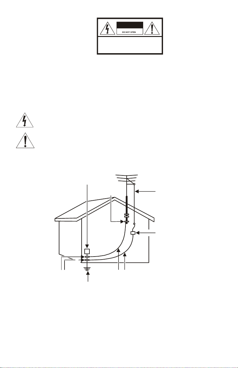
EXAMPLE OF ANTENNA GROUNDING
Electric service
equipment
Ground
clamp
Antenna lead
in wire
Antenna
discharge unit
(NEC Section 810-20)
Grounding
clamps
Power service grounding
electrode system
(NEC Article 250, Part H)
NEC=NATIONAL ELECTRICAL CODE
Grounding conductors
(NEC Section 810-21)
Page 3

IMPORTANT SAFETY INSTRUCTIONS
1 Read instructions
All the safety and operating instructions should be read before the appliance is operated.
2 Retain instructions
The safety and operating instructions should be retained for future reference.
3 Heed warnings
All warnings on the appliance and in the operating instructions should be adhered to.
4 Follow instructions
All operating and use instructions should be followed.
5 Cleaning
Unplug this product from the wall outlet before cleaning. Do not use liquid cleaners or aerosol
cleaners. Use a damp cloth for cleaning.
6 Attachments
Do not use attachments not recommended as they may cause hazard.
7 Water and moisture
Do not use this equipment near water; for example, near a bathtub, wash bowl, kitchen sink, or
laundry-tub, in a wet basement, or near a swimming pool, and the like.
8 Accessories
Do not place this product on an unstable cart, stand, tripod, bracket, or table. The product may fall
causing serious injury and serious damage to the appliance. Use only with a cart, stand, tripod,
bracket, or table recommended by the manufacturer, or sold with the equipment. Any mounting of
the appliance should follow the manufacturer’s instructions, and should use a mounting accessory
recommended by the manufacturer.
9 Ventilation
Slots and openings in the cabinet are provided for ventilation and to ensure reliable operation of
the equipment and to protect it from overheating. The openings should never be blocked by
placing the product on a bed, sofa, rug, or similar surface. Equipment should never be placed near
or over a radiator or heat register, or in a built-in installation such as a bookcase or rack unless
proper ventilation is provided.
10 Power sources
This product should be operated only from the type of power sources indicated on the marking
label. If you are not sure of the type of power supplied to your home, consult your local power
company. For equipment intended to operate from battery power, or other sources, refer to the
operating instructions.
11 Ground or polarization
This equipment may be equipped with a polarized alternating-current line plug (a plug having one
blade wider than the other). This plug will fit into the power outlet only one way. This is a safety
feature. If you are unable to insert the plug fully into the outlet, try reversing the plug. If the plug
should still fail to fit, contact your electrician to replace your obsolete outlet. Do not defeat the
safety purpose of the polarized plug.
This equipment may be equipped with a 3-wire grounding-type plug, a plug having a third
(grounding) pin. This pin will only fit into a grounding-type power outlet. This is a safety feature. If
you are unable to insert the plug into the outlet, contact your electrician to replace your obsolete
outlet. Do not defeat the safety purpose of the grounding-type plug.
12 Power cord protection
Power supply cords should be routed so that they are not likely to be walked on or pinched by
items placed upon or against them, paying particular attention to cords at plugs, convenience
receptacles, and the point where they exit from the appliance.
Page 4

IMPORTANT SAFETY INSTRUCTIONS
13 Outdoor antenna grounding
If an outside antenna or cable system is connected to the equipment, be sure the antenna or cable
system is grounded as to provide some protection against voltage surges and built-up static
charges. Article 810 of the National Electrical Code, ANSI/NFPA 70, provides information with
regard to proper grounding of the mast and supporting structure, grounding of the lead-in wire to
an antenna discharge unit, size of grounding conductors, location of antenna-discharge unit,
connection to grounding electrodes, and requirements for the grounding electrode.
14 Lightning
For added protection for this equipment during a lightning storm, or when it is left unattended and
unused for long periods of time, unplug it from the wall outlet and disconnect the antenna or cable
system. This will prevent damage to the video product due to lightning and power line surges.
15 Power lines
An outside antenna system should not be located in the vicinity of overhead power lines or where it
can fall into such power lines or circuits. When installing an outside antenna system, extreme care
should be taken to keep from touching such power lines or circuits, as contact with them may be
fatal.
16 Overloading
Do not overload wall outlets and extension cords as this can result in a risk of fire or electrical
shock.
17 Object and liquid entry
Never push objects of any kind into this equipment through openings, as they may touch
dangerous voltage points or short-out parts that could result in a fire or electrical shock. Never spill
liquid of any kind on the product.
18 Servicing
Do not attempt to service this equipment yourself, as opening or removing covers may expose you
to dangerous voltage or other hazards, refer all servicing to qualified service personnel.
19 Replacement parts
When replacement parts are required, be sure the service technician has used replacement parts
specified by the manufacturer or have the same characteristics as the original part. Unauthorized
substitutions may result in fire, electric shock, or other hazards.
20 Safety check
Upon completion of any service to this video product, ask the service technician to perform safety
checks to determine that the product is in proper operational condition.
Page 5

Regulatory Information
Federal Communications Commission Radio and Television Interface Statement for a Class ‘B’
Device
This equipment has been tested and found to comply with the limits for a Class B digital device,
pursuant to part 15 of the FCC Rules. These limits are designed to provide reasonable protection
against harmful interference in the residential installation. This equipment generates, uses and can
radiate radio frequency energy and, if not installed and used in accordance with the instructions, may
cause harmful interference to radio communications. However, there is no guarantee that interference
will not occur in a particular installation.
If the equipment does cause harmful interference to radio or television reception, which can be
determined by turning the equipment off and on, the user is encouraged to try to correct the interference
by one of the following measures:
• Increase the separation between the equipment and the affected receiver
• Connect the equipment on a circuit different from the one the receiver is on
Changes or modification not expressly approved by the party responsible for compliance could void the
user’s authority to operate the equipment.
Declaration of Conformity
According to 47 CFR, Parts 2 and 15 for Class B Personal Computers and Peripherals; and/or CPU
Boards and Power Supplies used with Class B Personal Computers, Motorola, Inc., 6450 Sequence
Drive, San Diego, CA 92121, 1-800-225-9446, declares under sole responsibility that the product
identifies with 47 CFR Part 2 and 15 of the FCC Rules as a Class B digital device. Each product
marketed is identical to the representative unit tested and found to be compliant with the standards.
Records maintained continue to reflect the equipment being produced can be expected to be within the
variation accepted, due to quantity production and testing on a statistical basis as required by 47 CFR
2.909. Operation is subject to the following condition: This device must accept any interference received,
including interference that may cause undesired operation. The above named party is responsible for
ensuring that the equipment complies with the standards of 47 CFR, Paragraphs 15.101 to 15.109. The
Class B digital apparatus meets all requirements of the Canadian Interface Causing Equipment
Regulations.
Canadian Compliance
This Class B digital apparatus complies with Canadian ICES-003. Cet appareil numérique de la classe
B est conforme à la norme NMB-003 du Canada.
Page 6

Contact Us
For technical support of your Receiver, call Motorola Support at 1-866-668-2271 or 1-866-MOT-BCS1.
For Motorola consumer cable products, education, and support:
http://www.motorola.com/broadband/consumers
__________________________________________________________________________________
Copyright © 2004 Motorola, Inc.
All rights reserved. No part of this publication may be reproduced in any form or by any means or used
to make any derivative work (such as translation, transformation or adaptation) without written
permission from Motorola, Inc.
Motorola reserves the right to revise this publication and to make changes in content from time to time
without obligation on the part of Motorola to provide notification of such revision or change. Motorola
provides this guide without warranty of any kind, either implied or expressed, including but not limited to,
the implied warranties of merchantability and fitness for a particular purpose. Motorola may make
improvements or changes in the product(s) described in this manual at any time.
MOTOROLA and the Stylized M Logo are registered in the US Patent & Trademark Office. Dolby Digital
manufactured under license from Dolby Laboratories Licensing Corporation. Dolby and the double-D
symbol are registered trademarks of Dolby Laboratories Licensing Corporation. All other product or
service names are the property of their respective owners. Certain third party trademarks are used
throughout this manual for explanatory purposes only. The depiction of any third party trademark in
typed form, or graphical form, in this manual should not be taken to imply any relationship, sponsorship,
endorsement, license between Motorola, Inc. and the owner of such third party trademark, or any other
affiliation. Such trademarks, and graphical representations thereto, include “What’s New Scooby-Doo”
and “Jackie Chan Adventures” and are the property of their respective owners. Further, any other third
party trademarks not listed herein are the property of their respective owners.
Page 7

CONTENTS
OVERVIEW ...............................................................................................3
Digital TV Options..................................................................................4
HDT101 Components............................................................................ 4
What You’ll Need to Get Started ...........................................................4
FRONT PANEL......................................................................................... 5
REMOTE CONTROL ................................................................................6
INSTALLING THE HDT101 ...................................................................... 8
Connecting Video .................................................................................. 9
Connecting Component Video (YPbPr) ........................................... 10
Connecting S-Video or Composite Video ........................................11
Connecting Audio ................................................................................12
Connecting the Antenna and Power Cord...........................................13
FINDING DIGITAL TV STATIONS IN YOUR AREA..............................14
PROGRAMMING YOUR HDT101 ..........................................................15
OPERATION...........................................................................................18
Choosing Your Screen Format............................................................18
Using the i-Banner to View Program Information................................20
Tuning to a Channel ............................................................................22
Using Closed Captioning .....................................................................23
Advanced Closed Captioning...........................................................23
ON-SCREEN MENU ...............................................................................24
Selecting Favorite Channels................................................................25
Tuning to Favorite Channels ...............................................................26
Setting Parental Controls.....................................................................27
V-Chip ..............................................................................................27
Understanding V-Chip Ratings ........................................................ 28
Movie Ratings...............................................................................28
TV Ratings....................................................................................29
Channel Lock ...................................................................................30
Changing Your Password.................................................................... 32
Setting the HDT101’s Clock for Your Time Zone ................................33
Adding a Channel ................................................................................34
Changing the On-Screen Menu Transparency....................................36
Page 8

Customizing the i-Banner ....................................................................36
Customizing Closed Captioning Styles ...............................................37
Reset Data........................................................................................... 38
CONNECTING OTHER DEVICES TO THE HDT101.............................39
Connecting your VCR and Standard TV .............................................39
Connecting your A/V Receiver, VCR, and High-definition TV.................40
Connecting your A/V Receiver, VCR, and Stereo TV .........................42
HDT101 ON-SCREEN MENU STRUCTURE .........................................44
TROUBLESHOOTING............................................................................45
2
Page 9

OVERVIEW
The Motorola® HDT101 High-definition Off-Air Receiver gives you access
to free “over-the-air” digital television signals for your HDTV-ready home
entertainment system or HDTV-capable monitor. If you are located in
one of the local markets served by over-the-air digital broadcasts, you
can start receiving high-definition signals with your HDT101 and an
antenna.*
The HDT101 offers:
• Conversion of all formats of digital TV signals to match your TV:
• 480i
• 480p
• 720p
• 1080i
• Support for all 18 ATSC (Advanced Television Systems
Committee) digital broadcast formats
• Storage capacity of up to 1,500 digital channels
• Three different video output connections: Component (YPbPr),
S-Video, and Composite
®
• Full movie-quality sound through Dolby
pass-through for connection to your home theater system
Digital decode or
• An easy to use on-screen menu that allows you to see program
information and TV schedules, switch between favorite channels,
and a host of other convenient functions
• Parental control features
• Closed captioning
*A separate antenna with a coaxial cable (not included) is required to
receive over-the-air digital TV signals.
3
Page 10

Digital TV Options
The HDT101 is compatible with all of the available types of digital
television:
Digital TV Type Description
High-definition television
(HDTV)
Enhanced-definition television
(EDTV)
Standard-definition television
(SDTV)
The highest picture quality with a
widescreen (16:9) aspect ratio.
HDTVs can accept all video formats:
1080i, 720p, 480p, 480i.
Displays a higher quality 480 progressive
image, either in a square (4:3) aspect ratio
or widescreen (16:9) aspect ratio.
EDTVs convert all video formats, including
higher resolution formats such as 720p or
1080i, to a 480p image.
480i video format. Delivers a better picture
quality than analog TV, but less than the
480p of EDTVs.
HDT101 Components
The following items are packed with your HDT101:
• Remote control with batteries
• Audio (Left/Right) cables
• Component video (YPbPr) cables
• HDT101 User Guide
• HDT101 Quick Setup Guide
What You’ll Need to Get Started
To set up your HDT101, you’ll need:
• A TV antenna, either outdoor or indoor
• A coaxial cable to attach the antenna to your HDT101
4
Page 11
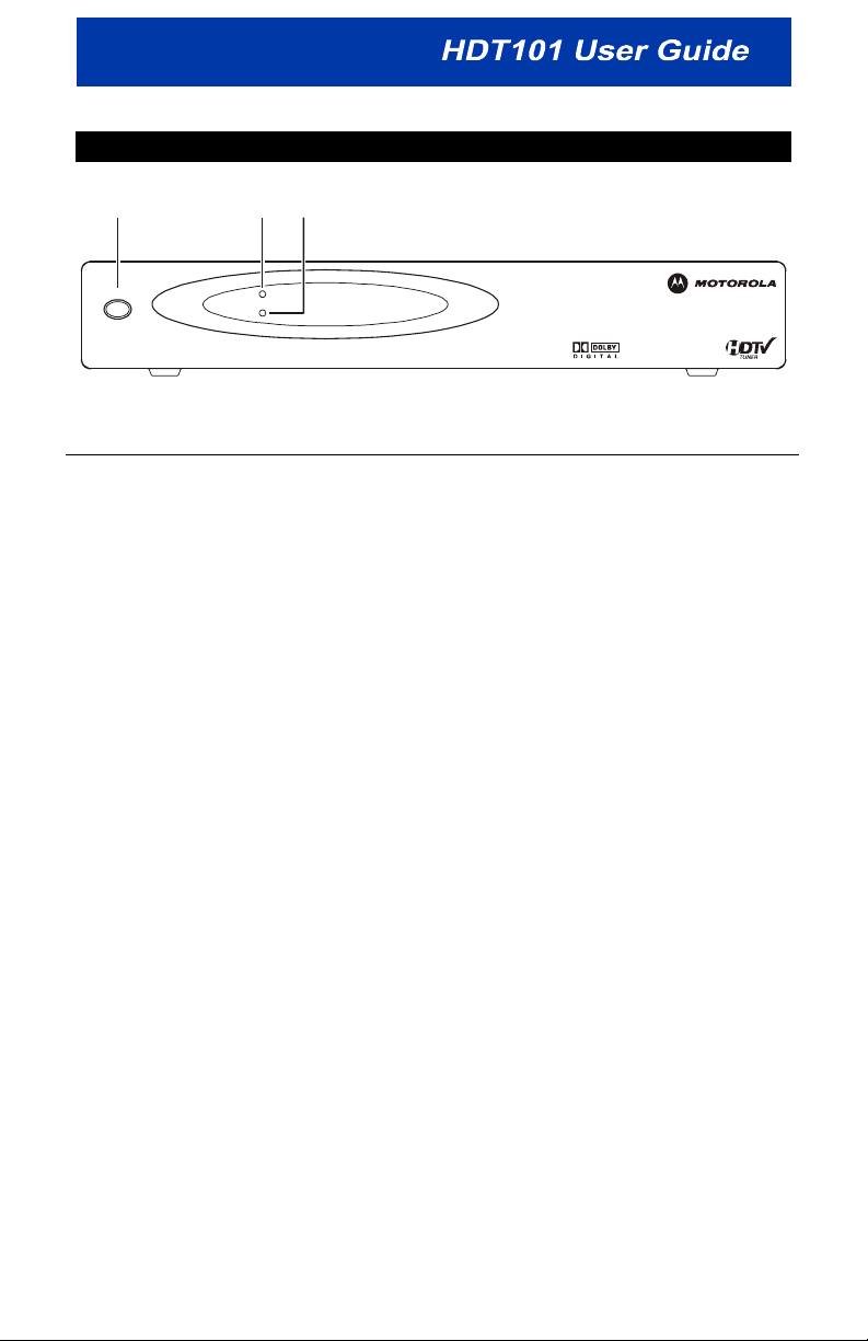
FRONT PANEL
12
POWER
SIGNAL LOSS
3
POWER
Item Description
1
2
3
POWER button
POWER LED
SIGNAL LOSS
LED
Puts the HDT101 in standby mode. To turn the
HDT101 on, simply press
Lights to indicate the HDT101 is turned on.
Lights to indicate the signal has been lost for the
channel you are currently viewing. See
“Troubleshooting” in the back of this User Guide for
assistance.
POWER again.
5
Page 12
REMOTE CONTROL
1
10
2
11
3
4
5
6
7
8
9
Audio Info
List Exit
Fav.
Select
CH+ Vol.+
CH-
V.F o rm at A. R at io
Menu
Vol .-
12
13
14
15
16
17
18
6
Page 13

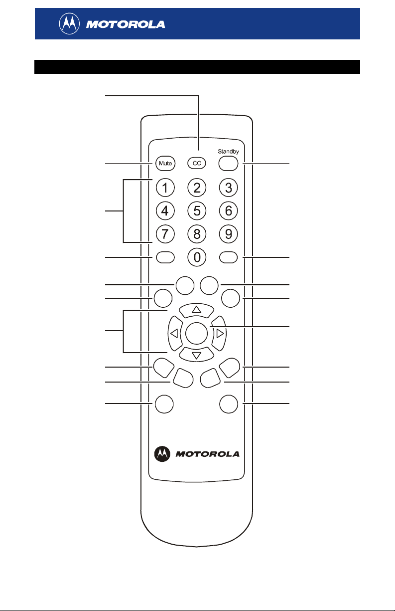
Button Description
1
2
CC
M
UTE
3 Number keys
4
5
6
AUDIO
L
IST
F
AV
7 Arrow keys
8
9
10
11
12
13
14
15
16
17
18
CH +
CH
-
V
. FORMAT
S
TANDBY
I
NFO
XIT
E
M
ENU
S
ELECT
V
OL +
V
OL -
A
. RATIO
Selects/disables closed captioning.
Mutes the volume.
Use the number keys to enter a channel number or
password.
Displays the audio languages available for the current
program.
Displays all available channels.
Displays the Favorite Channel list.
Navigate the on-screen menu. Change channels up
and down.
Changes the channels up.
Changes the channels down.
For use with component video output (YPbPr). Toggles
between the video formats:
• 480i
• 480p
• 720p
• 1080i
Select the video output format that is best for your TV’s
screen and capabilities.
Puts the HDT101 in standby mode. To turn the
HDT101 on, simply press STANDBY again.
Displays the i-Banner, which provides detailed
information about the current channel.
Exits the current on-screen menu.
Displays the on-screen menu.
Selects an item on the on-screen menu.
Increases the volume.
Decreases the volume.
Selects the aspect ratio (the shape of your picture
display).
Consult the manual supplied with your TV to determine
the recommended aspect ratio. For more information,
see “Choosing Your Screen Format.”
7
Page 14

INSTALLING THE HDT101
Connecting your HDT101 is quick and easy. Just complete three steps:
• Connect the video
• Connect the audio
• Connect the antenna and power cord
Before you connect your HDT101, please review the following:
• Disconnect power from the HDT101 before connecting or changing
cable connections.
• Do not place anything on top of the HDT101, especially other
home entertainment components.
If you wish to connect your HDT101 to your VCR or home theater
receiver, see the additional connection diagrams at the back of this
manual.
8
Page 15

Connecting Video
Before connecting your TV to the HDT101, you must determine which
type of video connection is accepted by your TV. The HDT101 offers
three different video options:
• Component video (YPbPr)
• S-Video
• Composite video
High-definition video can only be viewed with component video
connections.
To determine whether your TV features component video, S-Video or
composite video, check the manual supplied with your TV to determine
the best connection available.
9
Page 16
Connecting Component Video (YPbPr)
Component video provides the highest level of picture quality. If your
television has component video inputs (Y, Pb, and Pr connectors),
connect to the component video connections on your HDT101 instead of
the Video or S-Video connections.
HDT101
LR
LR
RF IN S/PDIF OUT S-VIDEO
Component
Vide o Input
Y
Pb
Pr
TV
RS-232
RS-232
AUDIO
AUDIO
YPbPr
YPbPr
VIDEO
VIDEO
DC INRF IN S/PDIF OUT S-VIDEO
DC IN
Component video cable
A fan is not included with some models.
To connect component video:
Connect the component video cable supplied with the HDT101 to the Y,
Pb, and Pr connectors on your TV and HDT101. The cables are
color-coded to assist you in making the correct connections.
Once you complete your video connections, proceed to the instructions
for the audio connections.
10
Page 17
Connecting S-Video or Composite Video
High-definition video can only be viewed with component video
connections. S-Video and composite video do not offer high-definition
video.
HDT101
LR
AUDIO
VIDEO
RF IN S/PDIF OUT S-VIDEO
RS-232
YPbPr
DC IN
Video cableS-Video cable
Either / or
TV
INPUT
S-VIDEO
VIDEO
To connect S-Video:
Connect an S-Video cable (not supplied) to the
S-VIDEO connector on
your HDT101 and the INPUT S-VIDEO connector on your TV.
To connect composite video:
Connect a video cable (not supplied) to the
VIDEO connector on your
HDT101 and the INPUT VIDEO connector on your TV.
Now proceed to the next step—connecting your audio connections.
11
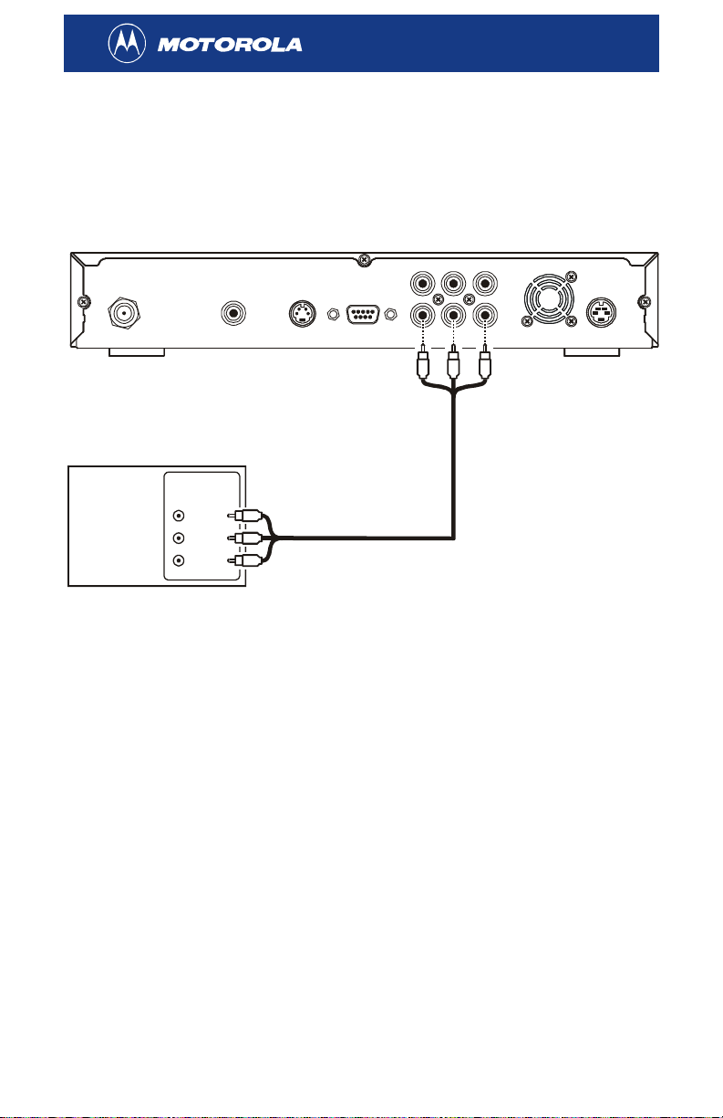
Page 18

Connecting Audio
AUDIO
LR
HDT101
VIDEO
RF IN
S/PDIF OUT S-VIDEO
RS-232
YPbPr
DC IN
TV
INPUT
AUDIO LEFT
AUDIO RIGHT
Audio cable
To connect your audio connections:
Connect the stereo audio cable supplied with your HDT101 to the
L and
R connectors on the HDT101 and the INPUT AUDIO LEFT and RIGHT
connectors on your TV.
Now proceed to the next step—connecting your antenna and power
cord.
12
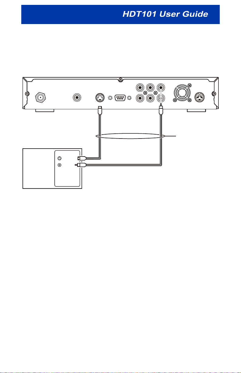
Page 19

a
Connecting the Antenna and Power Cord
LR
AUDIO
HDT101HDT101
VIDEO
RF IN S/PDIF OUT S-VIDEO
Coaxial cable to
antenn
RS-232
YPbPr
DC IN
Power cord to
wall outlet
You can use an outdoor or indoor antenna to receive over-the-air
high-definition TV signals:
1 Connect your antenna’s coaxial cable to the RF IN connector on your
HDT101.
2 Plug the power cord supplied with your HDT101 into the HDT101’s
power connector and then plug the cord into a wall outlet.
Now that you’ve completed connecting your HDT101, proceed to
“Finding Digital TV Stations in Your Area” on the following page.
13
Page 20

FINDING DIGITAL TV STATIONS IN YOUR AREA
After connecting your HDT101, you need to find the digital TV (DTV)
stations available in your area:
1 Log on to the following website:
http://www.antennaweb.org/
2 Select Choose An Antenna.
3 Enter your address and find the DTV stations airing the
HDTV/EDTV/SDTV signals you can receive.
For more information on the types of DTV signals, see “Digital TV
Options” on page 4.
You can also use the AntennaWeb website to get information on
choosing the correct antenna type and instructions for positioning the
antenna for the DTV station you want to watch.
NAB (National Association of Broadcasters) has updates on the local
DTV stations in operation. View them at:
http://www.nab.org/Newsroom/Issues/digitaltv/DTVstations.asp
Now you’re ready to program your HDT101 with over-the-air digital TV
stations. Proceed to “Programming Your HDT101” on the following page.
14
Page 21

PROGRAMMING YOUR HDT101
Before you can start using the HDT101, you need to program it with the
station numbers of the over-the-air digital TV stations available in your
area. This can be done by simply running auto scan from the HDT101’s
on-screen menu.
You can navigate the on-screen menu using the HDT101’s remote
control:
• Press the S and Tarrow keys to move up and down the on-screen
menu.
• Press the
on-screen menu.
• Press the
or to leave the main menu.
To program your HDT101:
SELECT button to select the highlighted item on the
EXIT button to return to the main menu from a submenu
1 Press POWER on the HDT101’s remote control to turn on the receiver.
2 Press MENU. The main menu is displayed:
3 Using the Tarrow key, highlight Installation and press SELECT. The
Password window is displayed.
15
Page 22

4 Enter your four-digit password. If you have not yet created your own
password, enter the default password: 0000. The Installation menu is
displayed:
If you wish to change your password, see “Changing Your
Password” on page 32.
5 Highlight Auto Scan and press SELECT.
The HDT101 starts scanning from Channels 2 to 69. The entire scan
may take several minutes. An indicator is displayed showing the
progress of the scan:
16
Page 23

As each digital TV signal is scanned, you’ll see the signal’s channel
number and the network/channel name displayed on the Program
List:
The auto scan ends on channel 69 and the message “Scan
Complete” is displayed.
6 Press EXIT to return to the main menu.
7 Press EXIT again to exit the main menu and start enjoying digital TV
programs.
If the picture displayed on your TV is too small, press the
button on your remote control to change the picture size. For more
information, see “Choosing Your Screen Format” on page 18.
17
A. RATIO
Page 24

OPERATION
Once your HDT101 is connected to your antenna and TV and you’ve
added your TV channels, you can enjoy digital over-the-air TV programs.
Simply use the remote control supplied with your HDT101 to change
channels, view program information, and navigate the on-screen menus.
If you encounter any problems while operating your HDT101, please
refer to the Troubleshooting section in the back of this manual.
Choosing Your Screen Format
The HDT101 offers several options for aspect ratio (the format of your
viewing screen).
Consult the following formats to determine the format to use for your type
of monitor and incoming video signal. Note that the “best” aspect ratio
may differ depending on the setup of the currently broadcast program.
To select an aspect ratio, press the
control to select the aspect ratio.
A. RATIO button on your remote
18
Page 25

If you have a 16:9 TV:
Pillarbox
Stretch
Features vertical black bars on
either side of a 4:3 program
shown on a widescreen 16:9
television screen.
Since the majority of television
content is 4:3, these bars allow
the original program to be seen
in its intended format without
distortion or stretching.
Features a picture that has been
“stretched” to fill the full screen
display with no black bars.
Programs will appear distorted
from their original presentation.
If you have a 4:3 TV:
Letterbox
Zoom
Features black horizontal bars
that preserve the original 16:9
aspect ratio when watching a
widescreen-formatted movie on
a standard 4:3 television.
Note: Letterbox is not available
for 1080i video output mode.
On 4:3 TVs, the 16:9 aspect
ratio is maintained by filling the
picture vertically and cropping
horizontally to fit.
Squeeze
Features a picture that has
been “squeezed” to fill the full
screen display with no black
bars. Programs will appear
distorted from their original
presentation.
19
Page 26

Using the i-Banner to View Program Information
If you want to learn more about the channel you are watching, press INFO
on your remote control and the HDT101 i (Information)-Banner will be
displayed:
The i-Banner will not display if you are viewing the HDT101’s on-screen
menu. Exit the on-screen menu and then press
control to view the i-Banner.
INFO on your remote
20
Page 27

The i-Banner provides the following information about the channel you
are viewing:
• Current channel number (and sub-channel number, if applicable)
If the current channel is on your Favorites list and you are viewing
in Favorites mode, a heart is displayed around the channel
number. See “Selecting Favorite Channels” for more information.
• Date
• Current local time (as provided by the local TV network)
• Network name
• Names of the current and next program (if provided by the local TV
network)
• Signal level and quality
• The type of incoming video signal – either HD or SD
• The type of incoming audio signal
To view extended program information about the channel you are
currently viewing, press
your screen. A program listing is displayed for the current channel (if
provided by the local TV network).
INFO again with the i-Banner still displayed on
To exit any of the windows, press
EXIT on your remote control.
The i-Banner will disappear from your screen after a set period of time.
To change your i-Banner settings, see “Configuring Your i-Banner
Settings” in the On-Screen Menu section.
If the time display in the i-Banner is incorrect, please contact your local
TV network.
21
Page 28

Tuning to a Channel
Use either of the following methods to tune to a channel:
Press the S and Tarrow keys on your remote control to navigate to the
desired channel.
Enter the channel number using the number keys.
You cannot tune to a sub-channel using the number keys on your remote
control. You must first enter the channel number and then use the S and
T keys to tune to the sub-channel you wish to view.
If sub-channels exist within a channel, the sub-channel numbers are
shown with a dash after the channel number. In the sample screenshot
on page 25, channel 5 has two sub-channels, labeled 1 and 2. Channel
5, sub-channel 2, is displayed.
You cannot tune to a sub-channel using the number keys on your remote
control. You must first enter the channel number and then use the S and
T keys to tune to the sub-channel you wish to view.
To quickly navigate to the channels you view most often, set those
channels as Favorites. See “Selecting a Favorite Channel” on page 25.
22
Page 29

Using Closed Captioning
To turn closed captioning off or on:
1 Press CC on your remote control to display the Closed Captioning
Settings.
2 Using the S and T keys, highlight CC1 to select primary closed
captioning (in English) or highlight CC2 to select secondary closed
captioning (in an alternate language).
To turn off closed captioning, highlight Disable CC.
3 Press SELECT.
Some programs may not transmit closed captioning.
Advanced Closed Captioning
Some programs offer advanced closed captioning. These programs will
list different languages under Closed Captioning Settings. Simply use the
S and T keys to highlight the desired language and then press
If a language is listed in the Closed Captioning Settings with –E after it,
this closed caption service will offer more expanded descriptions than
regular closed captioning.
If a language is listed with –W after it, the closed caption service has
been designed specifically for widescreen TVs (16:9).
SELECT.
23
Page 30

ON-SCREEN MENU
You can use the HDT101’s on-screen menu to:
• Select favorite channels
• Set up parental controls
• Set the HDT101’s time zone
• Add a channel
• Customize the on-screen menu and i-Banner
• Customize closed captioning
Instructions for completing the tasks listed above, as well other
on-screen menu functions, are included in this section.
You can navigate the on-screen menu using the HDT101’s remote
control:
• Press the S and Tarrow keys to move up and down the on-screen
menu.
• Press the
SELECT button to select the highlighted item on the
on-screen menu.
• Press the
EXIT button to return to the main menu from a submenu
or to exit the main menu.
24
Page 31

Selecting Favorite Channels
If there are certain channels you wish to access quickly, you can set
them as favorites in the HDT101 on-screen menu.
To set your favorites:
1 Press MENU on the remote control. The main menu is displayed.
2 Highlight Edit Channel and press SELECT. The Password window is
displayed.
3 Enter your four-digit password. If you have not yet created your own
password, enter the default password: 0000. The Edit Channel
window is displayed:
If you wish to change your password, see “Changing Your
Password” on page 32.
4 Press the S and T keys to select the channel you wish to set as a
favorite.
5 Press the X key to highlight the FAV column for that channel and
press SELECT. The “favorite” icon appears in the column.
6 Press EXIT twice to exit the on-screen menu.
25
Page 32

Tuning to Favorite Channels
Favorite channels can be quickly accessed from the Favorite Channels
List:
1 Press FAV on the remote control. The Favorite Channels List is
displayed.
2 Press the ST keys to highlight the channel you wish to view and
then press SELECT. The channel is displayed.
Selecting a channel using the Favorites Channels List puts the HDT101
in Favorites mode, meaning you can use the ST or
scroll up and down through your favorite channels.
To exit Favorites mode and view your non-favorite channels, do either of
the following:
• Enter a non-favorite channel number using the number keys on
your remote control.
CH +/CH - keys to
• Press
LIST and select a non-favorite channel from the list.
26
Page 33

Setting Parental Controls
The HDT101 offers two options for parental controls:
• V-Chip – blocks programming based on movie and TV ratings
systems.
• Channel Lock – blocks a channel or channels so it cannot be
viewed without a password. This can be done independently for
each channel.
V-Chip
You can use the V-Chip technology to block certain types of
programming from being viewed. The V-Chip settings are based on the
MPAA (Motion Picture Advisory Association) and TV ratings systems.
Once you set the rating limit in the V-Chip Setup menu, programming at
or beyond that rating limit cannot be viewed.
To configure your V-Chip settings:
1 Press MENU on the remote control. The main menu is displayed.
2 Highlight Installation and press SELECT. The Password window is
displayed.
3 Enter your four-digit password. If you have not yet created your own
password, enter the default password: 0000. The Installation menu is
displayed.
If you wish to change your password, see “Changing Your
Password” on page 32.
4 Highlight V-Chip Setup and press SELECT. The V-Chip Setup
window is displayed.
5 Press the STW X keys to highlight the desired rating limit(s) and
then press SELECT. The Lock symbol is displayed next to your
selections.
See “Understanding V-Chip Ratings” on page 28 for information
about MPAA Ratings, TV Ratings, and Content Themes.
6 When finished, press EXIT twice to exit the on-screen menu.
If a program or movie is blocked by the V-Chip, the following message is
displayed when someone attempts to view the program or movie:
Program is rating blocked by V-Chip Settings.
27
Page 34

To clear a V-Chip setting:
1 Press MENU on the remote control. The main menu is displayed.
2 Highlight Installation and press SELECT. The Password window is
displayed.
3 Enter your four-digit password. If you have not yet created your own
password, enter the default password: 0000. The Installation menu is
displayed.
If you wish to change your password, see “Changing Your
Password” on page 32.
4 Highlight V-Chip Setup and press SELECT. The V-Chip Setup
window is displayed.
5 Press the STW X keys to highlight the desired rating limit(s) and
then press SELECT. The Lock symbol is removed from your
selections.
6 Press EXIT twice to exit the on-screen menu.
Understanding V-Chip Ratings
When viewing movies, the V-Chip allows you to block various types of
movies based on their MPAA ratings. Once you select a rating limit, any
movie at or beyond that rating will be blocked. (This does not apply to
NR, which must be selected separately.)
Movie Ratings
NR
G
PG
PG-13
R
NC-17
X
NOT RATED BY THE MPAA. Some content may not be appropriate
for children.
GENERAL AUDIENCES. Appropriate for all ages.
PARENTAL GUIDANCE SUGGESTED. Some material may not be
suitable for children.
PARENTS STRONGLY CAUTIONED. Some material may be
inappropriate for children under 13.
RESTRICTED. Some material may be inappropriate for those under
17.
NO ONE 17 AND UNDER. Material is inappropriate for those 17 or
under.
ADULTS ONLY.
28
Page 35

TV programming can be blocked using the U.S. TV Programs ratings.
Once you select the rating limit, programming at or beyond that rating
limit cannot be viewed. (This does not apply to TV-Y and TV-Y7; they
must be selected separately.)
TV Ratings
TV-Y
TV-Y7
TV-G
TV-PG
TV-14
TV-MA
Content
Not
Rated
ALL CHILDREN. The themes and elements in this program are
specifically designed for a very young audience, including children
from ages 2-6.
DIRECTED TO OLDER CHILDREN. Themes and elements in this
program may include mild physical or comedic violence, or may
frighten children under the age of 7.
GENERAL AUDIENCE. It contains little or no violence, no strong
language, and little or no sexual dialogue or situations.
PARENTAL GUIDANCE SUGGESTED. The program may contain
infrequent coarse language, limited violence, some suggestive sexual
dialogue and situations.
PARENTS STRONGLY CAUTIONED. This program may contain
sophisticated themes, sexual content, strong language and more
intense violence.
MATURE AUDIENCES ONLY. This program may contain mature
themes, profane language, graphic violence, and explicit sexual
content.
NOT RATED.
Warning: If you select NR, you may inadvertently block emergency
bulletins such as weather warnings, as well the following types of
programming:
• Locally originated programming
• News
• Political
• Public service announcements
• Religious
• Sports
• Weather
Some of the TV ratings also have content themes that can be blocked:
FV
V
S
L
D
Fantasy/cartoon violence
Violence
Sex
Offensive language
Dialogue with sexual content
29
Page 36

Channel Lock
You can lock a specific channel or channels so they cannot be viewed
without entering a password.
To lock a channel (or remove a channel lock):
1 Press MENU on the remote control. The main menu is displayed.
2 Highlight Edit Channel and press SELECT. The Password window is
displayed.
3 Enter your four-digit password. If you have not yet created your own
password, enter the default password: 0000. The Edit Channel
window is displayed:
If you wish to change your password, see “Changing Your
Password” on page 32.
4 Press the S and T keys to select the channel you wish to lock.
5 Press the X key to highlight the Lock column for that channel and
press SELECT. The lock icon appears in the column.
To remove a channel lock, select the channel, press the X key to
highlight the Lock column for that channel, and press
lock icon is removed.
SELECT. The
6 Press EXIT twice to exit the on-screen menu.
The following message is displayed when attempting to view a locked
channel:
Program is under guard.
30
Page 37

To view the locked channel, enter your password. The channel will be
unlocked for as long as you stay tuned to it. If you tune to another
channel and return to the locked channel, the locked message is
displayed and you will have to re-enter your password.
31
Page 38

Changing Your Password
The preset default password in the HDT101 is 0000.
To change the password:
1 Press MENU on the remote control. The main menu is displayed.
2 Highlight System and press SELECT. The System menu is displayed.
3 Highlight Password and press SELECT.
4 Enter the current password or the default password (0000) if this is
the first time.
5 Using the number keys on the remote control, type in your new
four-digit password.
6 Re-enter your password to confirm it.
7 Press EXIT twice to exit the on-screen menu.
32
Page 39

Setting the HDT101’s Clock for Your Time Zone
You cannot change the time displayed on your HDT101. It is controlled
by your broadcaster.
To change the time zone for the HDT101’s clock:
1 Press MENU on the remote control. The main menu is displayed.
2 Highlight Installation and press SELECT. The Password window is
displayed.
3 Enter your four-digit password. If you have not yet created your own
password, enter the default password: 0000. The Installation menu is
displayed.
If you wish to change your password, see “Changing Your
Password” on page 32.
4 Highlight Clock Setup and press SELECT. The Local Time window is
displayed:
5 Press the W and X keys to change the time zone. When you are
finished, Press EXIT twice to exit the on-screen menu.
33
Page 40

Adding a Channel
If you wish to add a specific channel to your program list, follow these
steps for adding a single channel:
1 Log on to the following website:
http://www.antennaweb.org/
2 Select Choose An Antenna.
3 Enter your address and find the DTV stations airing the
HDTV/EDTV/SDTV signals you can receive.
For more information on the types of DTV signals, see “Digital TV
Options” on page 4.
4 Write down the channel number(s) you wish to add.
When adding a channel, you must add both the channel number and
its sub-channel number (when applicable). In the AntennaWeb site,
the sub-channel number is shown after a period. For example, if
channel 6 has several sub-channels, they would be listed as 6.1, 6.2,
etc. On the HDT101, sub-channel numbers are shown after a -; for
example, 6-1, 6-2, 6-3, etc.
5 Press MENU on the remote control. The main menu is displayed.
6 Highlight Installation and press SELECT. The Password window is
displayed.
7 Enter your four-digit password. If you have not yet created your own
password, enter the default password: 0000. The Installation menu is
displayed.
If you wish to change your password, see “Changing Your
Password” on page 32.
34
Page 41

8 Highlight Manual Scan and press SELECT. The Manual Scan window
is displayed:
9 Press the number keys on the remote control to enter the channel
number. Press the T key and then press SELECT to start the scan.
If the channel is successfully added, the “Get Channel Success”
message is displayed.
10 Press EXIT twice to exit the on-screen menu.
If the HDT101 cannot lock on the channel’s signal, a “Timeout error”
message is displayed. Adjust the antenna’s position and try adding the
channel again.
35
Page 42

Changing the On-Screen Menu Transparency
To make the on-screen menu transparent so you can still view TV
programs while displaying the menu:
1 Press MENU on the remote control. The main menu is displayed.
2 Highlight Menu Setup and press SELECT. The Menu Setup window is
displayed.
3 Highlight Transparency and press SELECT. The transparency
indicator bar is displayed.
4 Press the W and X keys to change the transparency of the
on-screen menu.
5 When finished, press EXIT twice to exit the on-screen menu.
Customizing the i-Banner
To configure how your i-Banner is displayed:
1 Press MENU on the remote control. The main menu is displayed.
2 Highlight Menu Setup and press SELECT. The Menu Setup window is
displayed.
3 Highlight i-Banner Setup and press SELECT. The i-Banner Setup
window is displayed.
4 Press the S and T keys to select an item. Press the W and X keys
to change a setting:
Fading Mode
Display Time
Time Format
Fade Out or No Fade
1-10 seconds
AM/PM or 24 hr
5 When finished, press EXIT twice to exit the on-screen menu.
36
Page 43

Customizing Closed Captioning Styles
The HDT101 allows you to customize your closed captioning in the
following ways:
• Caption style
• Character size
• Character style (font)
• Character color
• Edge type
• Background color
• Character opacity
• Background opacity
To customize your closed captioning:
1 Press MENU on the remote control. The main menu is displayed.
2 Highlight System and press SELECT. The System menu is displayed.
3 Highlight Caption Style and press SELECT. The Caption Style table
is displayed, with the current Caption Style setting highlighted.
4 Press the W and X keys to change the caption style. The options
are:
• As Broadcast – the closed captioning style is controlled by
the broadcast program.
• Small Text – the text size for displaying closed captioning is
smaller than the standard size.
• Large Text – the text size for displaying closed captioning is
larger than the standard size.
• Custom – allows you to customize your closed captioning.
5 If you wish to customize the appearance of your closed captioning,
press the W and X keys to highlight Custom in the Caption Style
setting.
6 Press the S and T keys to select an item. Press the W and X keys
to change a setting.
7 When finished, press EXIT three times to exit the on-screen menu.
37
Page 44

Reset Data
To erase your settings and restore the HDT101’s default settings:
1 Press MENU on the remote control. The main menu is displayed.
2 Highlight Installation and press SELECT. The Password window is
displayed.
3 Enter your four-digit password. If you have not yet created your own
password, enter the default password: 0000. The Installation menu is
displayed.
4 Highlight Reset Data and press SELECT. The message “Are you
sure?” is displayed. This message is a reminder that your customer
settings will be replaced by the default settings.
5 Press the W key to highlight Yes and then press SELECT.
38
Page 45

V
A
A
CONNECTING OTHER DEVICES TO THE HDT101
Connecting your VCR and Standard TV
LR
AUDIO
HDT101
VIDEO
RF IN S/PDIF OUT
S-VID EO
RS-232
Audio cable
YPbPr
DC IN
Video cable
TVVCR
INPUT
INPUT
AUDIOLRVIDEO
OUTPUT
AUDIOLRVIDEO
IDEO
UDIO LEFT
UDIO RIGH T
1 Connect the stereo audio cable supplied with the HDT101 to the
L and R connectors on the HDT101 and the INPUT AUDIO R and L
connectors on the VCR.
2 Connect a video cable to the VIDEO connector on the HDT101 and
the INPUT VIDEO connector on the VCR.
If your equipment supports it, S-Video connections may be used in
place of the standard composite video connections. In most cases,
S-Video offers a higher level of standard-definition video quality than
composite video.
3 Connect a stereo audio cable to the OUTPUT AUDIO R and L
connectors on the VCR and the INPUT AUDIO RIGHT and LEFT
connectors on the TV.
4 Connect a video cable to the OUTPUT VIDEO connector on the VCR
and the
INPUT VIDEO connector on the stereo TV.
39
Page 46

A
A
V
Connecting your A/V Receiver, VCR, and High-definition TV
HDT101
LR
AUDIO
VIDEO
RF IN S/PDIF OUT
Coaxial cable
INPUT
AUDIO VIDEO
LR
Audio
cable
Video
cable
Stere o VCR
OUTPUT
AUDIOLRVIDEO
S-VID EO
DVD
VIDEO 2
VCR
OUT
RS-232
video cable
AUDIO
L
R
IN
YPbPr
COMPONENT
IDEO INPUT
Y
Pb
Pr
VIDEO
VIDEO S-VIDEO
A/V receiver
OPTICAL
TV/MONITO R
OUTPUT
Video cableComponent
SPDIF
SPEAKER
CONNECTORS
DC IN
TV
INPUT
S-VIDEO
VIDEO
UDIO LEFT
UDIO RIGHT
Video
cable
40
Page 47

Connecting your A/V Receiver, VCR, and High-definition TV
1 Connect the HDT101 ports to the Y, Pb, and Pr ports on your TV
using the supplied component video cables.
2 Connect a coaxial audio cable to the S/PDIF OUT connector on the
HDT101 and the SPDIF input connector on the A/V receiver.
3 Connect a video cable to the VIDEO connector on the HDT101 and
the CABLE/TV VIDEO connector on the A/V receiver.
If your equipment supports it, S-Video connections may be used in
place of the standard composite video connections. In most cases,
S-Video offers a higher level of standard-definition video quality than
composite video.
4 Connect a stereo audio cable to the VCR AUDIO OUT R and L
connectors on the A/V receiver and the INPUT AUDIO R and L
connectors on the stereo VCR.
When using the digital audio output (
baseband audio connections from the HDT101 to the A/V receiver
are not needed.
S/PDIF OUT), the left/right
5 Connect a stereo audio cable to the OUTPUT AUDIO OUT R and L
connectors on the stereo VCR and the VCR AUDIO IN R and L
connectors on the A/V receiver.
6 Connect a video cable to the INPUT VIDEO connector on the stereo
VCR and the VIDEO VCR OUT connector on the A/V receiver.
7 Connect a video cable to the OUTPUT VIDEO connector on the stereo
VCR and the VIDEO VCR IN connector on the A/V receiver.
8 Connect a video cable to the INPUT VIDEO connector on the TV and
the TV/MONITOR OUTPUT VIDEO connector on the A/V receiver.
To switch between viewing input from your VCR and input from your
HDT101, change your TV’s video inputs from the Component input to the
Video input. You may also need to change your A/V receiver’s video
input selection as well.
41
Page 48

A
A
Connecting your A/V Receiver, VCR, and Stereo TV
LR
AUDIO
VIDEO
HDT101
RF IN S/PDIF OUT
Coaxial cable
INPUT
AUDIO VIDEO
LR
Audio
cable
Video
cable
Stereo VCR
OUTPUT
AUDIOLRVIDEO
S-VIDEO
DVD
VIDEO 2
VCR
OUT
YPbPr
RS-232
DC IN
Video cable
TV
INPUT
S-VIDEO
VIDEO
UDIO LEFT
UDIO RIGHT
Video
cable
A/V receiver
L
VIDEO
VIDEO S-VIDEO
OPTICAL
TV/MONITOR
OUTPUT
SPDIF
SPEAKER
CONNECTORS
AUDIO
R
IN
42
Page 49

Connecting your A/V Receiver, VCR, and Stereo TV
1 Connect a coaxial cable to the S/PDIF OUT connector on the HDT101
and the SPDIF input connector on the A/V receiver.
When using the digital audio output (
baseband audio connections from the HDT101 to the A/V receiver
are not needed.
S/PDIF OUT), the left/right
2 Connect a video cable to the VIDEO connector on the HDT101 and
the
CABLE/TV VIDEO connector on the A/V receiver.
If your equipment supports it, S-Video connections may be used in
place of the standard composite video connections. In most cases,
S-Video offers a higher level of standard-definition video quality than
composite video.
3 Connect a stereo audio cable to the VCR AUDIO OUT R and L
connectors on the A/V receiver and the INPUT AUDIO R and L
connectors on the stereo VCR.
4 Connect a stereo audio cable to the OUTPUT AUDIO OUT R and L
connectors on the stereo VCR and the VCR AUDIO IN R and L
connectors on the A/V receiver.
5 Connect a video cable to the INPUT VIDEO connector on the stereo
VCR and the VIDEO VCR OUT connector on the A/V receiver.
6 Connect a video cable to the OUTPUT VIDEO connector on the stereo
VCR and the VIDEO VCR IN connector on the A/V receiver.
7 Connect a video cable to the INPUT VIDEO connector on the stereo TV
and the TV/MONITOR OUTPUT VIDEO connector on the A/V receiver.
To switch between viewing input from your VCR and input from your
HDT101, change your A/V receiver’s video inputs.
43
Page 50

A
V
HDT101 ON-SCREEN MENU STRUCTURE
To assist you in navigating the on-screen menu, here is a diagram
illustrating the menu paths:
MAIN MENU
EDIT CHANNEL
INSTALLATION
SYSTEM
MENU SETUP
EDIT CHANNEL
INSTALLATION
MANUAL SCAN
AUTO SCAN
V-CHIP SETUP
CLOCK SETUP
SYSTEM
PASSWORD
INFORMATION
MANUAL SCAN
UTO SCAN
-CHIP SETUP
CLOCK SETUP
PAS SW OR D
INFORMATION
TRANSPARENCY
MENU SETUP
TRANSPARENCY
i-BANNER SETUP
i-BANNER SETUP
44
Page 51

TROUBLESHOOTING
If you encounter a problem with your HDT101, review this
troubleshooting section before calling your service provider. This
information will help you quickly solve a problem. If you’re unable to
solve the problem, contact your service provider.
Problem Possible Solutions
The POWER LED on
the front panel does
not light up
No picture
Confirm the power cord is plugged into a functioning
power outlet.
Press POWER on the front panel to see if the LED
lights up.
Determine if the HDT101 is in standby mode by
pressing STANDBY on the remote control.
Verify that all cables are connected properly
(hand-tighten if necessary).
If you are watching TV using your VCR, be sure your
VCR is on.
Verify that the TV is directed to the proper input
source.
Your TV may not support the current video output
format. Press
V. FORMAT to try another format.
Poor picture
quality
Verify that all cables are connected properly
(hand-tighten if necessary).
Check the antenna and make sure it is aligned to the
correct direction.
Check the signal’s strength and quality. Press
display the i-Banner and review the color bars at the
bottom of the window. If any of the bars are red, adjust
your antenna and try again.
45
INFO to
Page 52

Problem Possible Solutions
No sound
Can view on-screen
menus but cannot
view any video
After installing the
HDT101 and running
Auto Scan, not all the
available channels
have been added
Cannot lock on a
signal when manually
adding a channel
No closed captioning Press CC on your remote control to verify that closed
Verify that all cables are connected properly
(hand-tighten if necessary).
Confirm that the volume settings on your HDT101 and
TV are properly set and not in "mute" mode.
Scan the channel again. Press
on-screen menu and select Installation > Manual
Scan.
If you have connected your HDT101 to an A/V
receiver, check your A/V receiver’s audio settings.
Check your V-Chip and Channel Lock settings. See
“Setting Parental Controls” for more information.
Add the missing channels manually. See “Adding a
Channel” in the On-Screen Menu section.
You may have to reposition your antenna to receive all
local channels, especially if different transmit towers
are being used by the networks. For more information,
visit http://www.antennaweb.org.
Verify the channel number is correct.
Check the antenna and make sure it is aligned to the
correct direction.
Check the signal’s strength and quality. Press
display the i-Banner and review the color bars at the
bottom of the window. If any of the bars are red, adjust
your antenna and try again.
captioning is not disabled.
MENU to display the
INFO to
Cannot receive
channels after
changing the
HDT101’s location
Review your closed captioning settings. Press MENU
to display the on-screen menu and select System >
Caption Style.
The current program may not broadcast closed
captioning.
You may have to reposition your antenna. Consult the
following web site:
http://www.antennaweb.org/
46
Page 53

Problem Possible Solutions
On-Screen Error
Messages
Weak Signal
Possible Solutions
Verify that the antenna cable is connected properly
(hand-tighten if necessary).
Check the antenna and make sure it is aligned to the
correct direction.
47
Page 54

Visit our website at:
www.broadband.motorola.com/consumers
515904-001
11/04
MGBI
 Loading...