


Professional Radio
GM Series
Controlhead
Service Information
Issue: September 2000

ii
Computer Software Copyrights
The Motorola products described in this manual may include copyrighted Motorola computer programs stored
in semiconductor memories or other media. Laws in the United States and other countries preserve for
Motorola certain exclusive rights for copyrighted computer programs, including the exclusive right to copy or
reproduce in any form, the copyrighted computer program. Accordingly, any copyrighted Motorola computer
programs contained in the Motorola products described in this manual may not be copied or reproduced in
any manner without the express written permission of Motorola. Furthermore, the purchase of Motorola
products shall not be deemed to grant, either directly or by implication, estoppel or otherwise, any license
under the copyrights, patents or patent applications of Motorola, except for the normal non-exclusive royaltyfree license to use that arises by operation of law in the sale of a product.

Table of Contents
Chapter 1 MODEL OVERVIEW
1.0 GM140/GM340/GM640 Models...........................................................................1-1
2.0 GM160/GM360/GM660 Models...........................................................................1-1
3.0 GM380/GM1280 Models......................................................................................1-2
Chapter 2 THEORY OF OPERATION
1.0 Introduction..........................................................................................................2-1
2.0 Controlhead Model for GM140, GM340 and GM640...........................................2-1
2.1 Power Supplies...............................................................................................2-1
2.2 Power On / Off................................................................................................2-1
2.3 Microprocessor Circuit....................................................................................2-1
2.4 SBEP Serial Interface.....................................................................................2-1
2.5 Keypad Keys...................................................................................................2-1
2.6 Status LED and Back Light Circuit .................................................................2-3
2.7 Microphone Connector Signals ......................................................................2-3
2.8 Speaker..........................................................................................................2-4
2.9 Electrostatic Transient Protection ...................................................................2-4
3.0 Controlhead Model for GM160, GM360 and GM660...........................................2-4
3.1 Power Supplies...............................................................................................2-4
3.2 Power On / Off................................................................................................2-4
3.3 Microprocessor Circuit....................................................................................2-5
3.4 SBEP Serial Interface.....................................................................................2-5
3.5 Keypad Keys...................................................................................................2-6
3.6 Status LED and Back Light Circuit .................................................................2-6
3.7 Liquid Crystal Display (LCD) ..........................................................................2-6
3.8 Microphone Connector Signals ......................................................................2-6
3.9 Speaker..........................................................................................................2-7
3.10 Electrostatic Transient Protection ...................................................................2-8
4.0 Controlhead Model for GM380 and GM1280.......................................................2-8
4.1 Power Supplies...............................................................................................2-8
4.2 Voltage Regulator Circuit................................................................................2-8
4.3 Power On / Off................................................................................................2-9
4.4 Microprocessor Circuit....................................................................................2-9
4.5 SBEP Serial Interface...................................................................................2-10
4.6 Keypad Keys.................................................................................................2-10
4.7 Status LED and Back Light Circuit ...............................................................2-10
4.8 Liquid Crystal Display (LCD) ........................................................................2-11
4.9 Microphone Connector Signals ....................................................................2-11
4.10 Speaker........................................................................................................2-12
4.11 Electrostatic Transient Protection .................................................................2-12
iii

iv
Chapter 3 TROUBLESHOOTING CHARTS
1.0 Troubleshooting Chart for Controlhead GM140/340/640 ....................................3-1
1.1 On/Off .................................................................................................................3-1
1.2 Microprocessor ...................................................................................................3-2
2.0 Troubleshooting Chart for Controlhead GM160/360/660 ....................................3-3
2.1 On/Off .................................................................................................................3-3
2.2 Microprocessor ...................................................................................................3-4
2.3 Display ................................................................................................................ 3-5
2.4 Backlight .............................................................................................................3-6
3.0 Troubleshooting Chart for Controlhead GM380/1280 .........................................3-7
3.1 On/Off .................................................................................................................3-7
3.2 Microprocessor ...................................................................................................3-8
3.3 Microprocessor ...................................................................................................3-9
3.4 Display .............................................................................................................. 3-10
3.5 Keypad Backlight ..............................................................................................3-11
3.6 Display Backlight ..............................................................................................3-12
Chapter 4 CONTROLHEAD PCB/SCHEMATICS/PARTS LISTS
1.0 Allocation of Schematics and Circuit Boards.......................................................4-1
2.0 Controlhead GM140/340/640 - PCB 8486146B07 / Schematics.........................4-3
2.1 Controlhead PCB 8486146B07 - Parts List.........................................................4-6
3.0 Controlhead GM160/360/660 - PCB 8486155B06 / Schematics ........................4-7
3.1 Controlhead PCB 8486155B06 - Parts List ......................................................4-12
4.0 Controlhead GM380/1280 - PCB 8486178B03 / Schematics............................4-13
4.1 Controlhead PCB 8486178B03 - Parts List.......................................................4-18
OVERVIEW
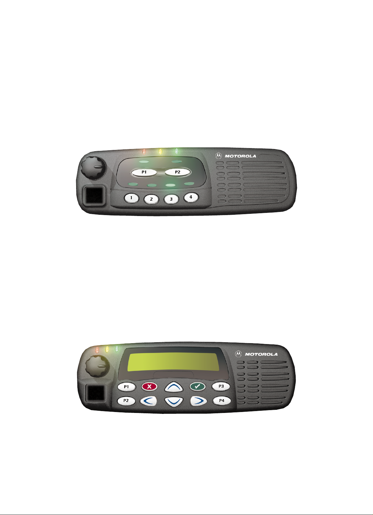
1.0 GM140/GM340/GM640 Models (GCN6112_)
The Controlhead contains the internal speaker, the on/off/volume knob, the microphone connector,
several buttons to operate the radio and several indicator Light Emitting Diodes (LED) to inform the
user about the radio status. To control the LED’s and to communicate with the host radio the control
head uses the Motorola 68HC11E9 microprocessor.
Chapter 1
2.0 GM160/GM360/GM660 Models
(GCN6114-GM160 / GCN6120-GM360/660)
The Controlhead contains the internal speaker, the on/off/volume knob, the microphone connector,
several b uttons to oper ate the radio, several indicator Light Emitting Diodes (LED) to inform the user
about the radio status, and a 14 character Liquid Crystal Display (LCD) for alpha - numerical
information e.g. channel number or call address name. To control the LED’s and the LCD, and to
communicate with the host radio the control head uses the Motorola 68HC11E9 microprocessor
1-2 overview
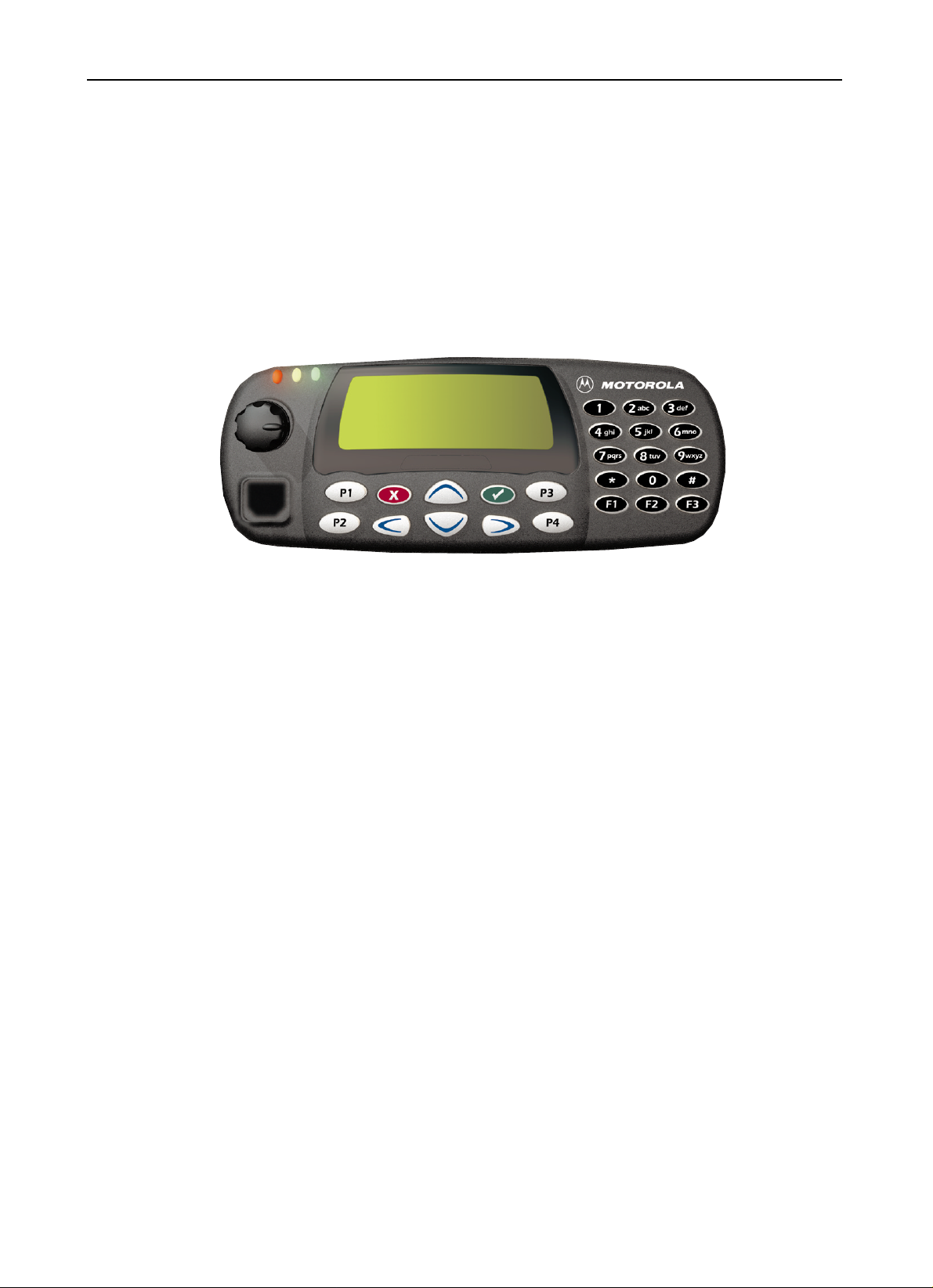
3.0 GM380/GM1280 Models (GCN6121_)
The Controlhead contains the on/off/volume knob, the microphone connector, several buttons to
operate the radio, several indicator Light Emitting Diodes (LED) to inform the user about the radio
status, and a Liquid Crystal Display (LCD) with 21 pre - defined symbols and a 32*96 dot matrix for
graphical or alpha - numerical information e.g. channel number, select code, call address name. To
control the LED’s and the LCD, and to communicate with the host radio the control head uses the
Motorola 68HC11K4 microprocessor.

THEORY OF OPERATION
1.0 Introduction
This Chapter provides a detailed theory of operation for the Controlhead circuits. For details of the
trouble shooting refer to the related Section of this manual.
2.0 Controlhead Model for GM140, GM340 and GM640
The controlhead contains the internal speaker, the on/off/volume knob, the microphone connector,
several buttons to operate the radio and several indicator Light Emitting Diodes (LED) to inform the
user about the radio status. To control the LED’s and to communicate with the host radio the controlhead uses the Motorola 68HC11E9 microprocessor.
2.1 Power Supplies
The power supply to the controlhead is taken from the host radio’s FLT A+ voltage via connector
J0801 pin 3 and the regulated +5V via connector J0801 pin 7. The voltage FLT A+ is at supply
voltage level and is used for the LED’s, the back light and to power up the radio via on / off / volume
knob. The stabilized +5 volt is used f or the microprocessor and the ke ypad b uttons. The voltage USW
5V derived from the FLT A+ voltage and stabilized by the series combination of R0822, VR0822 is
used to buffer the internal RAM of the microprocessor (U0831). C0822 allows the supply voltage
level to be disconnected for a couple of seconds without losing RAM parameters. Dual diode D0822
prevents radio circuitry from discharging this capacitor. When the supply voltage is applied to the
radio, C0822 is charged via R0822 and D0822. To avoid, that the µP enters the wrong mode when
the radio is switched on while the voltage across C0822 is still too low, the regulated 5V charge
C0822 via diode D0822.
Chapter 2
2.2 Power On / Off
The On/Off/V olume knob when pressed s witches the r adio’s voltage regulators on by connecting line
ON OFF CONTROL to line UNSW 5V via D0821. Additionally, 5 volts at the base of digital tr ansistor
Q0822 informs the controlhead’s microprocessor about the pressed knob. The microprocessor
asserts pin 62 and line CH REQUEST low to hold line ON OFF CONTROL at 5 volts via Q0823 and
D0821. The high line ON OFF CONTROL also informs the host radio, that the controlhead’s
microprocessor wants to send data via SBEP bus. When the radio returns a data request message,
the microprocessor will inform the radio about the pressed knob. If the radio was switched off, the
radio’s µP will s witch it on and vice v ersa. If the On/Off/Volume knob is pressed while the r adio is on,
the software detects a low state on line ON OFF SENSE, the radio is alerted via line ON OFF
CONTROL and sends a data request message. The controlhead µP will inform the radio about the
pressed knob and the radio’s µP will switch the radio off.
2.3 Microprocessor Circuit
The controlhead uses the Motorola 68HC11E9 microprocessor (µP) (U0831) to control the LED’s
and to communicate with the host radio. RAM and ROM are contained within the microprocessor
itself.
The microprocessor generates it’s cloc k using the oscillator inside the microprocessor along with a 8
MHz ceramic resonator (U0833) and R0920.

2-2 THEORY OF OPERATION
The microprocessor’s RAM is always powered to maintain parameters such as the last operating
mode. This is achieved by maintaining 5V at µP pin 25. Under normal conditions, when the radio is
off, USW 5V is formed by FLT A+ running to D0822. C0822 allows the battery voltage to be
disconnected for a couple of seconds without losing RAM parameters. Diode D0822 prevents radio
circuitry from discharging this capacitor.
There are 8 analogue to digital converter ports (A/D) on the µP . They are labeled within the device
block as PE0-PE7. These lines sense the voltage level ranging from 0 to 5V of the input line and
convert that level to a number ranging from 0 to 255 which can be read by the software to take
appropriate action.
Pin VRH is the high reference voltage for the A/D ports on the µP . If this voltage is lower than +5V
the A/D readings will be incorrect. Lik e wise pin VRL is the low reference for the A/D ports. This line is
normally tied to ground. If this line is not connected to ground, the A/D readings will be incorrect.
The microprocessor can determine the used keypad type and the controlhead ID by reading the
levels at ports PC0 – PC7. Connections JU0852/3/4 are provided by the individual keypads.
The MODB / MODA input of the µP must be at a logic „1" f or it to start ex ecuting correctly. The XIRQ
and the IRQ pins should also be at a logic „1".
V oltage sense device U0832 provides a reset output that goes to 0 volts if the regulated 5 volts goes
below 4.5 volts. This is used to reset the controller to prevent improper operation.
2.4 SBEP Serial Interface
The host radio (master) communicates to the controlhead µP (slave) through its SBEP b us . This bus
uses only line BUS+ for data transfer. The line is bi-directional meaning that either the radio or the
controlhead µP can drive the line. The microprocessor sends serial data via pin 50 and D0831 and
it reads serial data via pin 47. Whenever the microprocessor detects activity on the BUS+ line, it
starts communication.
When the host radio needs to communicate to the controlhead µP , it sends data via line BUS+. Any
transition on this line generates an interrupt and the µP starts communication. The host radio may
send data like LED and back light status or it may request the controlhead ID or the keypad ID.
When the controlhead µP wants to communicate to the host radio, the µP brings request line CH
REQUEST to a logic „0" via µP pin 62. This switches on Q0823, which pulls line ON OFF
CONTROL high through diode D0821. A low to high transition on this line informs the radio, that the
controlhead requires service. The host radio then sends a data request message via BUS+ and the
controlhead µP replies with the data it wanted to send. This data can be information like which key
has been pressed or that the volume knob has been rotated.
The controlhead µP monitors all messages sent via BUS+, but ignores any data communication
between host radio and CPS or Universal Tuner.
2.5 Keypad Keys
The controlhead keypad is a 6 - key keypad. All ke ys are configured as 2 analogue lines read by µP
pins 13 and 15 . The voltage on the analogue lines varies between 0 volts and +5 volts depending on
which key has been pressed. If no key is pressed, the voltage at both lines will be 5 volts. The key
configuration can be thought of as a matrix, where the two lines represent one row and one column.
Each line is connected to a resistive divider powered b y +5 volts . If a button is pressed, it will connect
one specific resistor of each divider line to ground level and thereby reduce the voltages on the
analogue lines The v oltages of the lines are A/D conv erted inside the µP (ports PE 0 - 1) and specify
the pressed button. To determine which key is pressed, the voltage of both lines m ust be considered.

Controlhead Model for GM140, GM340 and GM640 2-3
An additional pair of analogue lines and A/D µP ports (PE 3 – 2) is available to support a keypad
microphone, connected to the microphone connector J0811. Any microphone k ey press is processed
the same way as a key press on the controlhead.
2.6 Status LED and Back Light Circuit
All indicator LED’s (red, yellow, green) are driven by current sources. To change the LED status the
host radio sends a data message via SBEP bus to the controlhead µP . The controlhead µP
determines the LED status from the received message and switches the LED’s on or off via port PB
7 – 0 and port PA4. The LED status is stored in the µP ’s memory. The LED current is determined by
the resistor at the emitter of the respective current source transistor.
The back light for the keypad is controlled by the host radio the same way as the indicator LED’s
using µP port PA 5. The µP can switch the back light on and off under software control. The keypad
back light current is drawn from the FLT A+ source and controlled by 2 current sources. The LED
current is determined by the resistor at the emitter of the respective current source transistor.
2.7 Microphone Connector Signals
Signals BUS+, PTT IRDEC, HOOK, MIC, HANDSET AUDIO, FLT A+, +5V and 2 A/D converter
inputs are available at the microphone connector J0811. Signal BUS+ (J0811-7) connects to the
SBEP bus for communication with the CPS or the Universal Tuner. Line MIC (J0811-5) feeds the
audio from the microphone to the radio’s controller via connector J0801-4. Line HANDSET AUDIO
(J0811-8) feeds the receiver audio from the controller (J0801-6) to a connected handset. FLT A+,
which is at supply voltage level, and +5V are used to supply any connected accessory like a
microphone or a handset.
The 2 A/D converter inputs (J0811-9/10) are used for a microphone with keypad. A pressed key will
change the dc voltage on both lines. The voltages depend on which key is pressed. The µP
determines from the voltage on these lines which key is pressed and sends the information to the
host radio.
Line PTT IRDEC (J0811-6) is used to key up the radio’s transmitter. While the PTT button on a
connected microphone is released, line PTT IRDEC is pulled to +5 volts level by R0843. Transistor
Q0843 is switched on and causes a low at µP port PA2. When the PTT b utton is pressed, signal PTT
IRDEC is pulled to ground level. This switches off Q0843 and the resulting high level at µP port PA2
informs the µP about the pressed PTT button. The µP will inform the host radio about any status
change on the PTT IRDEC line via SBEP bus.
When line PTT IRDEC is connected to FLT A+ level, transistor Q0821 is switched on through diode
VR0821 and thereby pulls the lev el on line ON OFF CONTR OL to FLT A+ level. This s witches on the
radio and puts the radio’s µP in bootstrap mode. Bootstrap mode is used to load the firmware into
the radio’s flash memory (See controller subsection for more details).
The HOOK input (J0811-3) is used to inform the µP when the microphone´s hang-up switch is
engaged. Dependent on the CPS prog ramming the µP ma y tak e actions like turning the audio PA on
or off. While the hang up switch is open, line HOOK is pulled to +5 volts level by R0841. Transistor
Q0841 is switched on and causes a low at µP port PA1. When the HOOK switch is closed, signal
HOOK is pulled to ground level. This switches off R0841and the resulting high level at µP port PA1
informs the µP about the closed hang up switch. The µP will inform the host radio about any status
change on the HOOK line via SBEP bus.

2-4 THEORY OF OPERATION
2.8 Speaker
The controlhead contains a speaker for the receiver audio. The receiver audio signal from the
differential audio output of the audio amplifier located on the radio’s controller is fed via connector
J0801-10, 11 to the speaker connector P0801 pin 1 and pin 2. The speaker is connected to the
speaker connector P0801. The controlhead speaker can be disconnected if an external speaker,
connected on the accessory connector, is used.
2.9 Electrostatic T ransient Protection
Electrostatic transient protection is provided for the sensitive components in the controlhead by
diodes VR0811 VR00812 VR0816 - VR0817. The diodes limit any transient voltages to tolerable
levels. The associated capacitors provide Radio Frequency Interference (RFI) protection.
3.0 Controlhead Model for GM160, GM360 and GM660
The controlhead contains the internal speaker, the on/off/volume knob, the microphone connector,
several buttons to operate the radio, several indicator Light Emitting Diodes (LED) to inform the user
about the radio status, and a 14 character Liquid Crystal Display (LCD) for alpha - numerical
information e.g. channel number or call address name. To control the LED’s and the LCD, and to
communicate with the host radio the controlhead uses the Motorola 68HC11E9 microprocessor.
3.1 Power Supplies
The power supply to the controlhead is taken from the host radio’s FLT A+ voltage via connector
J0801 pin 3 and the regulated +5V via connector J0801 pin 7. The voltage FLT A+ is at battery level
and is used for the LED’s, the back light and to power up the radio via on / off / volume knob. The
stabilized +5 volt is used for the microprocessor, the display, the display driver and the keypad
buttons. The voltage USW 5V derived from the FLT A+ voltage and stabilized by the series
combination of R0822, VR0822 is used to buffer the internal RAM of the microprocessor (U0831).
C0822 allows the battery voltage to be disconnected for a couple of seconds without losing RAM
parameters. Dual diode D0822 prevents radio circuitry from discharging this capacitor. When the
supply voltage is applied to the radio , C0822 is charged via R0822 and D0822. To avoid that the µP
enters the wrong mode when the radio is switched on while the voltage across C0822 is still too lo w,
the regulated 5V charge C0822 via diode D0822.
3.2 Power On / Off
The On/Off/V olume knob when pressed s witches the radio’s voltage regulators on by connecting line
ON OFF CONTROL to line UNSW 5V via D0821. Additionally, 5 volts at the base of digital tr ansistor
Q0822 informs the controlhead’s microprocessor about the pressed knob. The microprocessor
asserts pin 62 and line CH REQUEST low to hold line ON OFF CONTROL at 5 volts via Q0823 and
D0821. The high line ON OFF CONTROL also informs the host radio, that the controlhead’s
microprocessor wants to send data via SBEP bus. When the radio returns a data request message,
the microprocessor will inform the radio about the pressed knob. If the radio was switched off, the
radio’s µP will s witch it on and vice v ersa. If the On/Off/Volume knob is pressed while the radio is on,
the software detects a low state on line ON OFF SENSE, the radio is alerted via line ON OFF
CONTROL and sends a data request message. The controlhead µP will inform the radio about the
pressed knob and the radio’s µP will switch the radio off.
 Loading...