

Page 1

CLK
USER GUIDE
Page 2

Page 3

English
CONTENTS
Contents. . . . . . . . . . . . . . . . . . . . . . . . . . . . .1
Computer Software Copyrights . . . . . . . . . .3
Safety . . . . . . . . . . . . . . . . . . . . . . . . . . . . . . .4
Batteries and Chargers Safety Information 5
Operational Safety Guidelines. . . . . . . . . . . . .6
Radio Overview . . . . . . . . . . . . . . . . . . . . . . .7
Parts Of The Radio . . . . . . . . . . . . . . . . . . . . .7
Built-in Antenna. . . . . . . . . . . . . . . . . . . . .8
Volume Control Button (+) . . . . . . . . . . . .8
INFO Button . . . . . . . . . . . . . . . . . . . . . . .8
Volume Control Button (–) . . . . . . . . . . . .8
Accessory Jack . . . . . . . . . . . . . . . . . . . . .8
Power Button . . . . . . . . . . . . . . . . . . . . . .8
MON Button . . . . . . . . . . . . . . . . . . . . . . .8
Menu/Lock Button . . . . . . . . . . . . . . . . . . .8
Push-To-Talk (PTT) Button. . . . . . . . . . . .9
Display icons . . . . . . . . . . . . . . . . . . . . . . . . . .9
Batteries and Chargers. . . . . . . . . . . . . . . .11
The CLK radio provides a Lithium-Ion battery
that comes in 1130 mAh capacity. . . . . . . .11
About the Li-Ion Battery . . . . . . . . . . . . .11
Installing the Lithium-Ion (Li-Ion) Battery 12
Removing the Lithium-Ion (Li-Ion) Battery
. . . . . . . . . . . . . . . . . . . . . . . . . . . . . . . . 12
Charging the Radio with the Single-Unit
Charger . . . . . . . . . . . . . . . . . . . . . . . 13
Charging A Standalone Battery . . . . . . . 14
LED Display Battery Indicators . . . . . . . 14
Charger LED Indicators . . . . . . . . . . . . . 15
Troubleshooting . . . . . . . . . . . . . . . . . . . . . 17
Getting Started . . . . . . . . . . . . . . . . . . . . . . 24
Turning radio ON/OFF . . . . . . . . . . . . . . . . . 24
Adjusting Volume. . . . . . . . . . . . . . . . . . 24
Selecting a Channel. . . . . . . . . . . . . . . . 24
Receiving a Call. . . . . . . . . . . . . . . . . . . 24
Talk Range . . . . . . . . . . . . . . . . . . . . . . 25
Menu Options. . . . . . . . . . . . . . . . . . . . . . . . 26
Selecting a Channel. . . . . . . . . . . . . . . . 27
Starting and Stopping Scan . . . . . . . . . . 27
Nuisance Channel Delete . . . . . . . . . . . 27
Setting Squelch Levels . . . . . . . . . . . . . 28
Hands-Free Use/VOX . . . . . . . . . . . . . . . . . 28
With Compatible VOX Accessories . . . . 28
Enabling and Disabling VOX . . . . . . . . . 29
CONTENTS
1
Page 4

English
Voice Announcement . . . . . . . . . . . . . . .29
Programming Features . . . . . . . . . . . . . . . .26
Sign of Life . . . . . . . . . . . . . . . . . . . . . . .26
PTT Hold. . . . . . . . . . . . . . . . . . . . . . . . .26
Transmit Time-Out Timer . . . . . . . . . . . .27
One Touch Volume . . . . . . . . . . . . . . . . .27
Call Tone. . . . . . . . . . . . . . . . . . . . . . . . .27
Reverse Burst . . . . . . . . . . . . . . . . . . . . .27
Use and Care . . . . . . . . . . . . . . . . . . . . . . . .30
Frequency and Code Charts . . . . . . . . . . .31
CTCSS And PL/DPL Codes . . . . . . . . . . . . .33
CONTENTS
Motorola Solutions Limited Warranty . . . .38
Accessories . . . . . . . . . . . . . . . . . . . . . . . . .40
Audio Accessories. . . . . . . . . . . . . . . . . . . . . 40
Battery. . . . . . . . . . . . . . . . . . . . . . . . . . . . . .40
Chargers . . . . . . . . . . . . . . . . . . . . . . . . . . . .40
Carry Accessories . . . . . . . . . . . . . . . . . . . . .41
2
Page 5

English
COMPUTER SOFTWARE COPYRIGHTS
The Motorola Solutions products described in
this manual may include copyrighted Motorola
Solutions computer programs stored in
semiconductor memories or other media. Laws
in the United States and other countries
preserve for Motorola Solutions certain
exclusive rights for copyrighted computer
programs, including, but not limited to, the
exclusive right to copy or reproduce in any form
the copyrighted computer program.
Accordingly, any copyrighted Motorola
Solutions computer programs contained in the
Motorola Solutions products described in this
manual may not be copied, reproduced,
modified, reverse-engineered, or distributed in
any manner without the express written
permission of Motorola Solutions.
Furthermore, the purchase of Motorola
Solutions products shall not be deemed to
grant either directly or by implication, estoppel,
or otherwise, any license under the copyrights,
patents or patent applications of Motorola
Solutions, except for the normal non-exclusive
license to use that arises by operation of law in
the sale of a product.
COMPUTER SOFTWARE
COPYRIGHTS
3
Page 6

English
SAFETY
RF ENERGY EXPOSURE AND
PRODUCT SAFETY GUIDE FOR
PORTABLE TWO-WAY RADIOS
ATTENTION!
Before using this product, read the RF Energy
Exposure and Product Safety Guide that ships
with the radio which contains instructions for
SAFETY
safe usage and RF energy awareness and
control for compliance with applicable
standards and regulation.
4
Page 7

English
BATTERIES AND CHARGERS SAFETY INFORMATION
This document contains important safety and
operating instructions. Read these instructions
carefully and save them for future reference.
Before using the battery charger, read all the
instructions and cautionary markings on
• the charger,
• the battery, and
• the radio using the battery
1. To reduce risk of injury, charge only the
rechargeable Motorola Solutions-authorized
batteries. Other batteries may explode, causing
personal injury and damage.
2. Use of accessories not recommended by
Motorola Solutions may result in risk of fire,
electric shock, or injury.
3. To reduce risk of damage to the electric plug
and cord, pull by the plug rather than the cord
when disconnecting the charger.
4. An extension cord should not be used unless
absolutely necessary. Use of an improper
extension cord could result in risk of fire and
electric shock. If an extension cord must be
used, make sure that the cord size is 18 AWG
for lengths up to 100 feet (30.48 m), and 16
AWG for lengths up to 150 feet (45.72 m).
5. To reduce risk of fire, electric shock, or injury, do
not operate the charger if it has been broken or
damaged in any way. Take it to a qualified
Motorola Solutions service representative.
6. Do not disassemble the charger; it is not
repairable and replacement parts are not
available. Disassembly of the charger may
result in risk of electrical shock or fire.
7. To reduce risk of electric shock, unplug the
charger from the AC outlet before attempting
any maintenance or cleaning
CHARGERS SAFETY
BATTERIES AND
5
Page 8

English
OPERATIONAL SAFETY GUIDELINES
• Turn the radio OFF when charging battery.
• The charger is not suitable for outdoor use. Use
only in dry locations/conditions.
• Connect charger only to an appropriately fused
and wired supply of the correct voltage (as
specified on the product).
• Disconnect charger from line voltage by removing
main plug.
• The outlet to which this equipment is connected
should be nearby and easily accessible.
SAFETY INFORMATION
• In equipment using fuses, replacements must
BATTERIES AND CHARGERS
comply with the type and rating specified in the
equipment instructions.
• Maximum ambient temperature around the power
supply equipment must not exceed 104 °F (40
°C).
• Power output from the power supply unit must not
exceed the ratings stated on the product label
located at the bottom of the charger.
• Make sure that the cord is located where it will
not be stepped on, tripped over, or subjected to
water, damage, or stress.
6
Page 9

English
RADIO OVERVIEW
MON button
Volume Control Button (+)
Accessory Jack
Built-in antenna
Power button
MENU/Lock button
Push-to-Talk (PTT)
button
LED Display
Volume Control Button (–)
INFO button
PARTS OF THE RADIO
RADIO OVERVIEW
7
Page 10

English
Built-in Antenna
The antenna for the CLK radio is non-removable.
Volume Control Button (+)
Short press – Increases the volume gradually.
Note: Use this button to scroll through menu items
when in Menu mode.
Long press – Increases the volume continuously.
INFO Button
Short press – Displays and announces current
channel and battery level.
To stop status display and Voice Announcement,
press this button again. The radio returns to idle
mode.
RADIO OVERVIEW
Volume Control Button (–)
Short press – Decreases the volume gradually.
Note: Use this button to scroll through menu items
when in Menu mode.
Long press – Decreases the volume continuously.
Accessory Jack
This jack is used to connect accessories like audio
accessory, programming cable, and other authorized
accessories.
Power Button
Long press/short press – Powers the radio on/off.
The Power button plays a different function when
pressed simultaneously with other buttons.
• When pressed with the Volume Control Button
(+), the radio powers up in factory reset mode.
• When pressed with the INFO button, the radio
powers up in cloning mode.
• When pressed with the Volume Control Button
(–), the radio establishes a connection with the
connected PC.
MON Button
Short press (during transmission) – Sends a Call
Tone.
Long press – The radio monitors for activity in the
channel.
Menu/Lock Button
Short press - Radio enters the Menu. Press again to
navigate from one menu setting to another.
Long press - Locks and unlocks the radio buttons,
except the Volume Control Buttons and PTT button.
8
Page 11

English
Push-To-Talk (PTT) Button
Press and hold down the PTT button to talk. Release
the PTT button to listen.
If the PTT hold feature is enabled, you can press the
PTT button to start transmitting and release the PTT
button while transmitting without terminating the
transmit activity.
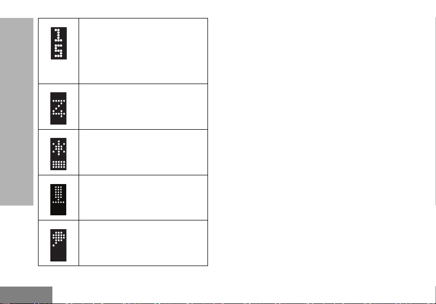
DISPLAY ICONS
The following icons are icons that appear on the LED
display of the radio.
Feature Enabled
This icon indicates that a feature is
being enabled.
Feature Disabled
This icon indicates that a feature is
being disabled.
Receiving
Indicates that the radio is receiving.
Transmitting
Indicates the radio is transmitting.
RADIO OVERVIEW
9
Page 12
English
RADIO OVERVIEW
Channel
Indicates the Channel number the
radio is currently in.
Note: Display icon differs
according to the current
channel the radio is in.
Scan
Indicates Scan feature in the Menu
setting.
Squelch Level
Indicates squelch level settings.
There are three squelch levels.
VOX
Initiates a hands-free voice
activated call.
Voice Announcement
If enabled, the radio audibly
indicates to announce the radio
operations.
10
Page 13

English
BATTERIES AND CHARGERS
The CLK radio provides a Lithium-Ion battery that comes in 1130 mAh capacity.
BATTERY FEATURES AND CHARGING
OPTIONS
About the Li-Ion Battery
The CLK radio comes equipped with a rechargeable
Li-Ion battery. This battery should be fully charged
before initial use to ensure optimum capacity and
performance.
Battery life is determined by several factors. Among
the more critical are the regular overcharge of
batteries and the average depth of discharge with
each cycle. Typically, the greater the overcharge and
the deeper the average discharge, the fewer cycles a
battery will last. For example, a battery which is
overcharged and discharged 100% several times a
day, lasts fewer cycles than a battery that receives
less of an overcharge and is discharged to 50% per
day. Further, a battery which receives minimal
overcharging and averages only 25% discharge, lasts
even longer.
Motorola Solutions batteries are designed specifically
to be used with a Motorola Solutions charger and vice
versa. Charging in non-Motorola Solutions equipment
may lead to battery damage and void the battery
warranty. The battery should be at about 77°F (25°C)
(room temperature), whenever possible. Charging a
cold battery (below 50° F [10°C]) may result in
leakage of electrolyte and ultimately in failure of the
battery. Charging a hot battery (above 95°F [35°C])
results in reduced discharge capacity, affecting the
performance of the radio. Motorola Solutions rapidrate battery chargers contain a temperature-sensing
circuit to ensure that batteries are charged within the
temperature limits stated above.
BATTERIES AND
CHARGERS
11
Page 14

English
Installing the Lithium-Ion (Li-Ion) Battery
Figure 1: Gently push
and slide the back
cover downward.
Figure 2: Insert the battery
and ensure that the battery
grooves are connected to
the radio grooves.
BATTERIES AND CHARGERS
1. Turn off the radio.
2. To remove the back cover of the radio, gently
12
press the back cover down and slide
downwards.
3. Insert the battery by connecting the grooves of
the battery to the grooves on the radio then,
push it down. Refer to Figure 1.
Note: To learn about the Li-Ion Battery Life
features, refer to “About the Li-Ion Battery”
on page 11.
Removing the Lithium-Ion (Li-Ion) Battery
1. Turn OFF the radio.
2. Gently push the back cover of the radio and
slide the cover down.
3. Lift and detach the battery from the radio.
Page 15

English
Charging the Radio with the Single-Unit
Figure 3: Connecting the radio to the single-
unit charger
Figure 4: Detaching the radio from the single-
unit charger
Push the ‘M’ logo and pull
the radio away from the
single-unit charger.
Charger
1. Ensure that the radio is switched off before
connecting the radio to the charger.
2. Connect the radio to the charger and make sure
that there is a clicking sound. Refer to Figure 3.
3. Plug the AC Adaptor into a power outlet.
4. To detach the radio from the charger, pull the
radio away from the charger while pressing the
logo down. Refer to Figure 4.
BATTERIES AND
CHARGERS
13
Page 16

English
Charging A Standalone Battery
Figure 5: Insert the
battery into the
single-unit charger
Figure 6: Battery is
attached to the
single-unit charger
LED Display Battery Indicators
Icon Comments
Battery is fully charged
Battery power is at a medium
level
Battery power level is low
BATTERIES AND CHARGERS
1. Remove the battery from the radio.
2. Insert the battery into the single-unit charger.
3. Plug the AC Adaptor into a power outlet.
14
Battery power level is
critically-low. An alert tone
sounds every 2 minutes.
Page 17

English
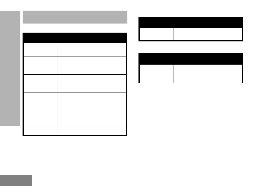
Charger LED Indicators
Table 1: Charger LED Indicator
Status LED Indicator
Charging
Charge
complete
Battery
fault
Steady Red
Indication
Steady Green
Indication
Blinking Red
Indication
15
Charging in
progress.
Battery is fully
charged.
Battery was
faulty when
inserted.
Re-inserting
the battery
solves the
issue.
BATTERIES AND
CHARGERS
Page 18

English
BATTERIES AND CHARGERS
Notes
16
Page 19

English
TROUBLESHOOTING
Symptom
Recharge or replace the Li-Ion battery.
No Power
Hearing other noises or
conversation on a
channel
Message Scrambled
Audio quality not good
enough
17
Extreme operating temperatures may affect battery life.
Refer to “Batteries and Chargers Safety Information” on page 5.
Confirm Interference Eliminator Code is set.
Frequency or Interference Eliminator Code may be in use.
Change settings: Change frequencies or codes on all radios.
Make sure radio is at the right frequency and code when transmitting.
Refer to “Frequency and Code Charts” on page 31.
Scramble Code might be ON, and/or setting does not match the other radio
settings.
Radio settings might not be matching up correctly. Double check frequencies,
codes, and bandwidths to make sure the radio settings are identical in all radios.
Try This...
TROUBLESHOOTING
Page 20

English
Symptom
Limited talk range
Message not
TROUBLESHOOTING
transmitted or received
Heavy static or
interference
Try This...
Steel and/or concrete structures, heavy foliage, buildings or vehicles decrease
range. Check for clear line of sight to improve transmission.
Wearing radio close to body such as in a pocket or on a belt decreases range.
Change location of radio. To increase range and coverage, you can reduce
obstructions or increase power. UHF radios provides greater coverage in industrial
and commercial buildings. Increasing power provides greater signal range and
increased penetration through obstructions.
Refer to “Talk Range” on page 25.
Make sure the PTT button is completely pressed when transmitting.
Confirm that the radios have the same Channel, Frequency, Interference Eliminator
Code and Scramble Code settings. Refer to “Frequency and Code Charts” on
page 31 for further information.
Recharge, replace and/or reposition batteries.
Obstructions and operating indoors, or in vehicles, may interfere. Change location.
Refer to “Talk Range” on page 25.
Verify that the radio is not in Scan. Refer to “Starting and Stopping Scan” on
page 27 and “Nuisance Channel Delete” on page 27.
Radios are too close; they must be at 1.5 meters apart.
Radios are too far apart or obstacles are interfering with transmission.
Refer to “Talk Range” on page 25.
18
Page 21

English
Symptom
Low batteries
Drop-in Charger LED
light does not blink
Low battery indicator is
blinking although new
batteries are inserted
Cannot activate VOX
Battery does not
charge although it has
been placed
in the drop-in charger
for a while
Try This...
Recharge or replace Li-Ion battery.
Extreme operating temperatures affect battery life.
Check that the radio/battery is properly inserted and check the battery/charger
contacts to ensure that they are clean and charging pin is inserted correctly.
Refer to “Charging the Radio with the Single-Unit Charger” on page 13, “Charging
the Radio with the Single-Unit Charger” on page 13 and “Installing the Lithium-Ion
(Li-Ion) Battery” on page 12.
Refer to “Installing the Lithium-Ion (Li-Ion) Battery” on page 12.
VOX feature might be set to OFF.
Accessory not working or not compatible.
Refer to “Hands-Free Use/VOX” on page 28.
Check drop-in tray charger is properly connected and correspond to a compatible
power supply.
Refer to “Charging the Radio with the Single-Unit Charger” on page 13 and
“Charging A Standalone Battery” on page 14.
Check the charger’s LEDs indicators to see if the battery has a problem.
Refer to “Charger LED Indicators” on page 15.
TROUBLESHOOTING
19
Page 22

English
GETTING STARTED
For the following explanations, refer to “Parts Of The
Radio” on page 7.
TURNING RADIO ON/OFF
To turn ON the radio, press the Power button. The
display shows the Channel for five seconds.
To turn the radio OFF, long press the Power button.
Adjusting Volume
To increase the volume, press the Volume Control
Button (+)
continuously, long press the Volume Control Button
(+)
GETTING STARTED
Notes: When listening through the earpiece, set the
button. To increase the volume
button.
volume to a level that is comfortable to your
hearing. Increasing the volume abruptly may
cause discomfort.
Selecting a Channel
1. Press the MENU button.
The channel number flashes on the LED
display.
2. Press the Volume Control Button (+/–) to the
required Channel.
The display shows the Channel name for five
seconds.
3. Press the PTT button to confirm the selected
Channel.
Receiving a Call
1. Select a channel by pressing the MENU button
then, press the Volume Control Button (+/–)
until you reach the desired channel.
The display shows the Channel name for five
seconds.
2. Make sure the PTT button is released and listen
for voice activity.
3. To respond, press the PTT button on the radio
or audio accessory to talk and release it to
listen.
24
Page 23

English
W A R N I N G
This radio is not encrypted,
any classified
communication as defined
by the law is prohibited. This
radio is subjected to
interference by other radios.
Talk Range
The CLK radio has been designed to maximize
performance and improve transmission range in the
field. It is recommended that you do no use the radios
closer than 1.5 meters apart, to avoid interference.
Under normal circumstances, the CLK radio coverage
is 7400 square meters, or up to 6 floors.
Talk range depends on the terrain. It will be affected
by concrete structures, heavy foliage and by operating
radios indoors or in vehicles. Optimal range occurs in
flat, open areas with up to 9 kilometers of coverage.
Medium range occurs when buildings and trees are in
the way.
To establish a proper two-way communication, the
Channel, Frequency and Interference Eliminator
Codes must be the same on both radios. This
depends on the stored profile that has been preprogrammed on the radio:
GETTING STARTED
25
Page 24

English
1. Channel: Current channel that the radio is
using, depending upon radio model.
2. Frequency: The frequency the radio uses to
transmit/receive.
3. Interference Eliminator Code: These codes
help minimize interference by providing a
choice of code combinations.
4. Scramble Code: Codes that make the
transmissions sound garbled to anyone
listening who is not set to that specific code.
GETTING STARTED
MENU OPTIONS
To access the radio menu, short press the MENU
button. If the voice announcement is enabled, you will
hear the “Main Menu” announcement.
Use the Volume Control Button (+/–) to scroll
through the menu items.
The LED display shows the current configurable
feature icon and setting. The features which are
configurable on the radio are as follow:
• Channel
• Scan
• Squelch Level
•VOX
• Voice Announcement
26
Page 25

English
Selecting a Channel
This feature is the first feature on the radio Menu. The
channel numbers that can be supported by the display
are Channel 1 to 16.
To change channels, press the Volume Control
Button (+/–).
To select a channel, press the PTT button or wait until
the display returns to the Home screen. The LED
display shows the new Channel number.
Starting and Stopping Scan
Scan allows you to monitor other channels to detect
conversations. When the radio detects a transmission,
it stops scanning and goes to the active channel. This
allows you to listen and talk to people in that channel
without having to change channel.
To activate the Scan feature, press the MENU button
until the Scan icon displays. Press the Vol ume
Control Button (+/–) to turn on or off the Scan
feature.
The radio only scans the channels which are
programmed in the Scan List for each channel
The radio does not automatically exit Scan mode after
the Menu timer expires. To exit Scan mode, press the
PTT button.
To pause Scan and return to the menu, press the
MENU button.
Nuisance Channel Delete
Nuisance Channel Delete allows you to temporarily
remove channels from the Scan List. This feature is
useful when irrelevant conversations on a ‘nuisance’
channel ties up the radio’s scanning feature.
To delete a channel from the Scan List:
• Start Scan mode by pressing the MENU button
then, navigate to the Scan feature and enable
scan by using the Volume Control Button (+/–).
• Wait until the radio stops receiving at the channel
you wish to eliminate. Long press the MON
button to delete the channel.
The channel will not be scanned again until you exit
the Scan mode by short pressing the PTT button or by
turning OFF the radio and back ON.
GETTING STARTED
27
Page 26

English
Setting Squelch Levels
You can adjust the squelch level of the radio to filter
out unwanted calls with low signal strength or
channels that have a higher than normal background
noise.
Press the MENU button until the Squelch icon
appears. To select squelch level, press the Vol um e
Control Button (+/–).
There are three squelch levels and the default squelch
level is Level 2. The levels are indicated by the
following icons:
Level 1
GETTING STARTED
Level 2
Level 3
To save squelch level and exit Menu, press the PTT
button.
HANDS-FREE USE/VOX
The CLK radio can operate hands-free (VOX) when
used with compatible VOX accessories.
With Compatible VOX Accessories
The default factory setting for VOX sensitivity level is
Medium (level ‘2’). To use VOX, perform the following
steps:
1. Turn the radio OFF.
2. Open accessory cover.
3. Insert the plug of the audio accessory firmly into
accessory port.
4. Turn radio ON.
5. Lower radio volume BEFORE placing
accessory near ear.
6. To transmit, speak into accessory microphone
and to receive, stop talking.
7. VOX can be temporarily disabled by pressing
the PTT button or by removing the audio
accessory.
Note: To order accessories, contact your Motorola
Solutions point of purchase
28
Page 27

English
Enabling and Disabling VOX
Press the Menu button until the VOX icon displays. To
enable or disable VOX, press the Volume Control
Button (+/–).
To save the VOX setting and exit the menu, press the
PTT button.
Voice Announcement
This feature enables the radio to audibly indicate the
radio operations. The Voice Announcement feature is
enabled by default.
To change the Voice Announcement setting, press the
MENU button until the Voice Announcement
displays. To turn the Voice Announcement on or off,
press the Volume Control Button (+/–).
icon
GETTING STARTED
29
Page 28

English
PROGRAMMING FEATURES
Your dealer or system administrator may have
customized your radio for your specific needs. Check
with your dealer or system administrator for more
information.
Sign of Life
When the radio is idle, the LED display lights up seven
seconds after the last detected activity. The display
lights up for 0.6 seconds to show that the radio is still
on but in idle mode.
The following image shows the animation of the ‘Sign
of Life’ feature.
PROGRAMMING FEATURES
PTT Hold
This feature allows you to press the PTT button to
start transmitting and release the PTT button while
transmitting without terminating the transmit activity.
The radio stops transmitting when the PTT button is
pressed again or when the time-out timer expires.
26
Page 29

English
Transmit Time-Out Timer
This timer sets the amount of time that the radio can
continuously transmit before the transmission is
automatically terminated. The default setting is 60
seconds.
One Touch Volume
This feature allows you to adjust the volume from the
current level to the preset level by pressing the PTT
button.
When this feature is enabled, the PTT button works as
a One Touch Volume button when an audio
accessory is connected to the radio.
The audio volume increases or decreases to the
preset value when the PTT button is pressed.
The PTT button functions as a transmit button when
this feature is disabled.
Call Tone
Call Tones feature allows you to transmit an audible
tone to other radios on the same channel to alert them
that you are about to talk or to alert them without
speaking.
Call Tone can be sent during transmission by pressing
the MON button.
Reverse Burst
Reverse Burst eliminates unwanted noise (squelch
tail) during loss of carrier detection.
PROGRAMMING FEATURES
27
Page 30
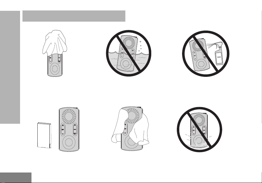
English
If the radio is submerged in water...
Use a soft damp cloth to
clean the exterior
USE AND CARE
USE AND CARE
Turn radio OFF and
remove batteries
30
Do not immerse in water
Dry with soft cloth Do not use radio until
Do not use alcohol or
cleaning solutions
completely dry
Page 31

English
FREQUENCY AND CODE CHARTS
The charts in this section provide Frequency and Code information. These charts are useful when
using the Motorola Solutions CLK two-way radios with other business radios.
FREQUENCY AND CODE
Default Channel Frequency and Interference Eliminator Code
#Channel Frequency (MHz) PL / DPL
1 446.00625 67.0 Hz
2 446.01875 67.0 Hz
3 446.03125 67.0 Hz
4 446.04375 67.0 Hz
5 446.05625 67.0 Hz
6 446.06875 67.0 Hz
7
8
9 446.00625 754
10 446.01875 754
11 446.03125 754
31
446.08125 67.0 Hz
446.09375 67.0 Hz
CHARTS
Page 32

English
.
CHARTS
FREQUENCY AND CODE
#Channel Frequency (MHz) PL / DPL
12 446.04375 754
13 446.05625 754
14 446.06875 754
15
16
446.08125 754
446.09375 754
32
Page 33

English
CTCSS AND PL/DPL CODES
CTCSS Codes
CTCSS Hz CTCSS Hz CTCSS Hz
1 67.0 16 114.8 31 192.8
2 71.9 17 118 .8 32 203.5
3 74.4 18 123 33 210.7
4 77.0 19 127.3 34 218.1
5 79.7 20 131.8 35 225.7
6 82.5 21 136.5 36 233.6
7 85.4 22 141.3 37 241.8
8 88.5 23 146.2 38 250.3
9 91.5 24 151.4 122 (*) 69.3
10 94.8 25 156.7 124 Customized CTCSS
11 97.4 26 162.2 125 Customized CTCSS
12 100.0 27 167.9 126 Customized CTCSS
13 103.5
14 107.2 29 179.9 128 Customized CTCSS
15 110 .9 30 186.2 129 Customized CTCSS
Note: (*) New CTCSS Code.
28 173.8 127 Customized CTCSS
FREQUENCY AND CODE
CHARTS
33
Page 34

English
CHARTS
FREQUENCY AND CODE
PL/DPL Codes
DPL Code DPL Code DPL Code
39 23 55 116 71 243
40 25 56 125 72 244
41 26 57 131 73 245
42 31 58 132 74 251
43 32 59 134 75 261
44 43 60 143 76 263
45 47 61 152 77 265
46 51 62 155 78 271
47 54 63 156 79 306
48 65 64 162 80 311
49 71 65 165 81 315
50 72 66 172 82 331
51 73 67 174 83 343
52 74 68 205 84 346
53 114 69 223 85 351
54 115 70 226 86 364
34
Page 35

English
PL/DPL Codes (Continued)
DPL Code DPL Code DPL Code
87 365 104 565 121 754
88 371 105 606 123 645
89 411
90 412 107 624 125 Customized PL
91 413 108 627 126 Customized PL
92 423 109 631 127 Customized PL
93 431 110 632 128 Customized PL
94 432 111 654 129 Customized PL
95 445 112 662 130 Inverted DPL 39
96 464 113 664 131 Inverted DPL 40
97 465 114 703 132 Inverted DPL 41
98 466 115 712 133 Inverted DPL 42
99 503 116 723 134 Inverted DPL 43
100 506 11 7 731 135 Inverted DPL 44
101 516 11 8 732 136 Inverted DPL 45
102 532 11 9 734 137 Inverted DPL 46
103 546 120 743 138 Inverted DPL 47
106 612 124 Customized PL
FREQUENCY AND CODE
CHARTS
35
Page 36

English
CHARTS
FREQUENCY AND CODE
PL/DPL Codes (Continued)
DPL Code DPL Code DPL Code
139 Inverted DPL 48 156 Inverted DPL 65 173 Inverted DPL 82
140 Inverted DPL 49 157 Inverted DPL 66 174 Inverted DPL 83
141 Inverted DPL 50 158 Inverted DPL 67 175 Inverted DPL 84
142 Inverted DPL 51 159 Inverted DPL 68 176 Inverted DPL 85
143 Inverted DPL 52 160 Inverted DPL 69 177 Inverted DPL 86
144 Inverted DPL 53 161 Inverted DPL 70 178 Inverted DPL 87
145 Inverted DPL 54 162 Inverted DPL 71 179 Inverted DPL 88
146 Inverted DPL 55 163 Inverted DPL 72 180 Inverted DPL 89
147 Inverted DPL 56 164 Inverted DPL 73 181 Inverted DPL 90
148 Inverted DPL 57 165 Inverted DPL 74 182 Inverted DPL 91
149 Inverted DPL 58 166 Inverted DPL 75 183 Inverted DPL 92
150 Inverted DPL 59 167 Inverted DPL 76 184 Inverted DPL 93
151 Inverted DPL 60 168 Inverted DPL 77 185 Inverted DPL 94
152 Inverted DPL 61 169 Inverted DPL 78 186 Inverted DPL 95
153 Inverted DPL 62 170 Inverted DPL 79 187 Inverted DPL 96
154 Inverted DPL 63 171 Inverted DPL 80 188 Inverted DPL 97
155 Inverted DPL 64 172 Inverted DPL 81 189 Inverted DPL 98
36
Page 37

English
PL/DPL Codes (Continued)
DPL Code DPL Code DPL Code
190 Inverted DPL 99 200 Inverted DPL 109 210 Inverted DPL 119
191 Inverted DPL 100 201 Inverted DPL 110 211 Inverted DPL 120
192 Inverted DPL 101 202 Inverted DPL 111 212 Inverted DPL 121
193 Inverted DPL 102 203 Inverted DPL 112 213 Inverted DPL 123
194 Inverted DPL 103 204 Inverted DPL 113 214 Customized DPL
195 Inverted DPL 104 205 Inverted DPL 114 215 Customized DPL
196 Inverted DPL 105 206 Inverted DPL 115 216 Customized DPL
197 Inverted DPL 106 207 Inverted DPL 116 217 Customized DPL
198 Inverted DPL 107 208 Inverted DPL 117 218 Customized DPL
199 Inverted DPL 108 209 Inverted DPL 118 219 Customized DPL
FREQUENCY AND CODE
CHARTS
37
Page 38

English
MOTOROLA SOLUTIONS LIMITED WARRANTY
WARRANTY INFORMATION
The authorized Motorola Solutions dealer or
retailer where you purchased your Motorola
Solutions two-way radio and/or original
accessories will honor a warranty claim and/or
provide warranty service. Please return your
radio to your dealer or retailer to claim your
warranty service. Do not return your radio to
WARRANTY
Motorola Solutions. To be eligible to receive
warranty service, you must present your receipt
of purchase or a comparable substitute proof of
purchase bearing the date of purchase. The
two-way radio should also clearly display the
MOTOROLA SOLUTIONS LIMITED
serial number. The warranty will not apply if the
type or serial numbers on the product have
been altered, deleted, removed or made
illegible.
WHAT IS NOT COVERED BY THE
WARRANTY
• Defects or damage resulting from use of
the Product in other than its normal and
customary manner or by not following the
instructions in this user guide.
• Defects or damage from misuse, accident
or neglect.
• Defects of damage from improper testing,
operation, maintenance, adjustment or any
alteration or modification of any kind.
• Breakage or damage to aerials unless
caused directly by defects in material or
workmanship.
• Products disassembled or repaired in such
a manner as to adversely affect
performance or prevent adequate
inspection and testing to verify any
warranty claim.
• Defects or damage due to moisture, liquid
or spills.
• All plastic surfaces and all other externally
exposed parts that are scratched or
38
Page 39

English
damaged due to normal use.
• Products rented on a temporary basis.
• Periodic maintenance and repair or
replacement of parts due to normal usage,
wear and tear.
MOTOROLA SOLUTIONS LIMITED
WARRANTY
39
Page 40
English
ACCESSORIES
AUDIO ACCESSORIES
Part No.
HKLN4602_
HKLN4603_
HKLN4529_
ACCESSORIES
RLN6242_
PMLN7081_
AY000170A01 Earhook For PMLN7081_
AY000171A01 Earbud S/M/L For PMLN7081_
Description
Single pin earpiece with in-line
push-to-talk (PTT), PVC
Single pin surveillance earpiece
with push-to-talk (PTT), PVC
free
Single pin short cord earpiece
with push-to-talk (PTT), PVC
free
Quick disconnect acoustic tube
replacement
Earpiece with External Mic and
PTT (Changeable Eartips)
BATTERY
Part No. Description
HKNN4014_
Standard Li-Ion Battery BT60
1130 mAh
CHARGERS
Part No. Description
PMPN4488_
CLK Standard Drop-In Tray
Single Unit Charger with UK
adaptor
40
Page 41

English
CARRY ACCESSORIES COVER
Part No. Description
PMLN7078_R CLK Spring Belt Clip Kit
PMLN7079_R CLK Lanyard Kit
PMLN5231_R CLK Magnetic Belt Clip Kit
PMLN5232_R CLK Arm Band Kit
PMLN5233_R CLK Wrist Band Kit
Part No. Description
15012279001 Audio Jack Cover
ACCESSORIES
41
Page 42

English
Notes
ACCESSORIES
42
Page 43

Page 44

M
MOTOROLA, MOTO, MOTOROLA SOLUTIONS and the Stylized
M logo are trademarks or registered trademarks of Motorola
Trademark Holdings, LLC and are used under license.
All other trademarks are the property of their respective owners.
© 2019 Motorola Solutions, Inc.
All rights reserved.
*MN005790A01*
MN005790A01-AA
 Loading...