

Page 1
CG4500 Communications Gateway
User Guide
Q
intelligence everywhere”
Page 2
WARNING
TO PREVENT FIRE OR SHOCK HAZARD, DO NOT EXPOSE THIS APPLIANCE TO
RAIN OR MOISTURE.
CAUTION
TO PREVENT ELECTRICAL SHOCK, DO NOT USE THIS PLUG WITH AN
EXTENSION CORD, RECEPTACLE, OR OTHER OUTLET UNLESS THE
BLADES CAN BE FULLY INSERTED TO PREVENT BLADE EXPOSURE.
THE SOCKET-OUTLET SHALL BE NEAR THE EQUIPMENT AND EASILY
ACCESSIBLE WHEN THE PLUG OF THE POWER SUPPLY CORD IS USED AS
THE DISCONNECT DEVICE.
The lightning flash with arrowhead symbol, within an equilateral triangle, is
intended to alert the user to the presence of uninsulated “dangerous
1
This installation should be made by a qualified service person and should conform to all local codes.
REPAIRS
If you find the unit in need of repair, contact your cable system operator for repair or replacement.
voltage” within the product’s enclosure that may be of sufficient magnitude
to constitute a risk of electric shock to persons.
The exclamation point, within an equilateral triangle, is intended to alert the
user to the presence of important operating and maintenance (servicing)
instructions in the literature accompanying the appliance.
Page 3

Declaration of Conformity
We
declare under our sole responsibility that the
CG4500 Communications Gateway
to which this declaration relates is in conformity with one or more of the following standards:
Motorola, Inc.
101 Tournament Drive
Horsham, PA 19044, U.S.A.
EMC Standards
EN55022 EN55024 EN50083-2 CISPR-22 CISPR-24
Safety Standards
EN60065 EN60825 EN60950 lEC 60950 + Al: 1992 + A2: 1993 + A3: 1995 + A4: 1996
following the provisions of the Directive(s) of the Council of the European Union:
EMC Directive 89/336/EEC Low Voltage Directive 73/23/EEC
Page 4

A
CAUTION
THESE SERVICING INSTRUCTIONS ARE FOR USE BY QUALIFIED
PERSONNEL ONLY. TO REDUCE THE RISK OF ELECTRICAL SHOCK, DO
NOT PERFORM ANY SERVICING OTHER THAN THAT CONTAINED IN THE
INSTALLATION AND TROUBLESHOOTING INSTRUCTIONS UNLESS YOU
ARE QUALIFIED TO DO SO. REFER ALL SERVICING TO QUALIFIED SERVICE
PERSONNEL.
Repairs
If repair is necessary, contact your cable service provider.
Copyright © 2002 by Motorola, Inc.
All rights reserved. No part of this publication may be reproduced in any form or by any
means or used to make any derivative work (such as translation, transformation or
adaptation) without written permission from Motorola, Inc.
Motorola, Inc. reserves the right to revise this publication and to make changes in
content from time to time without obligation on the part of Motorola, Inc. to provide
notification of such revision or change. Motorola, Inc. provides this guide without
warranty of any kind, either implied or expressed, including, but not limited, to the
implied warranties of merchantability and fitness for a particular purpose. Motorola, Inc.
may make improvements or changes in the product(s) described in this manual at any
time.
MOTOROLA and the Stylized M Logo are registered in the US Patent & Trademark
Office. Microsoft and Windows are registered trademarks and Windows Me and
Windows XP are trademarks of Microsoft Corporation. Microsoft Windows screen
shots are used by permission of Microsoft Corporation. Macintosh is a registered
trademark of Apple Computer, Inc. UNIX is a registered trademark of the Open Group
in the United States and other countries. DOCSIS and PacketCable are trademarks of
Cable Television Laboratories, Inc. All other product or service names are the property
of their respective owners.
Page 5

CONTENTS
Introduction
..........................................................................
Front Panel.....................................................................................................................................................................................................3
Rear Panel......................................................................................................................................................................................................6
Before You Begin.......................................................................9
Installation..........................................................................12
For a Single User.........................................................................................................................................................................................12
Powering Up the First Time.........................................................................................................................................................................15
Using the Optional Cradle...........................................................................................................................................................................16
For Multiple Users........................................................................................................................................................................................17
Ethernet................................................................................................................................................................................................17
Ethernet and USB.................................................................................................................................................................................18
Basic Configuration...................................................................20
Configuring for TCP/IP.................................................................................................................................................................................20
Installing USB Device Drivers.....................................................................................................................................................................23
Verifying Your IP Address............................................................................................................................................................................24
Troubleshooting.......................................................................2R
1
Page 6
INTRODUCTION
The Motorola CG4500 Communications Gateway enables you to connect your home or business computer to a high-speed
Data Over Cable Service Interface Specification (DOCSIS ) 1.0 or l.l compliant data network. The CG4500 provides
high-speed, bi-directional data access with Radio Frequency (RF) downstream transfer rates up to 38 Mbps and RF upstream
rates up to l0 Mbps. It also provides telephony voice communication features using the Internet Protocol (IP) known as Voice
over IP (VoIP).
The CG4500 supports two separately dedicated telephone lines and unlike a dial-up modem, the CG4500 is always online. Just
open your browser and surf. Just pick up your phone and talk.
1
Page 7

INTRODUCTION
The CG4500 is compatible with industry standards and interfaces with major IP telephony vendor hardware. Features of the
CG4500 include:
Voice and data over a single coaxial cable network
Standard telephone features and CLASS features such as caller ID, call waiting, and call forwarding
Remote management through SNMP
Automatic configuration and address assignment
Software upgrades over the network
Compatible with Window^, Macintosh, and UNlUoperating system computers running Transport Control
ProtocolLInternet Protocol (TCP/IP)
Complies with industry standards (DOCSIS, PacketCable", etc.)
USB interface to a PC equipped with a USB port and running Windows 98 SE, Windows 2000, Windows Me", or
Windows XP
10/100 Base-T Ethernet port for direct connection to Ethernet equipped computers
Internet security lock switch on rear panel
Extensive event logs for troubleshooting
1
Page 8
INTRODUCTION
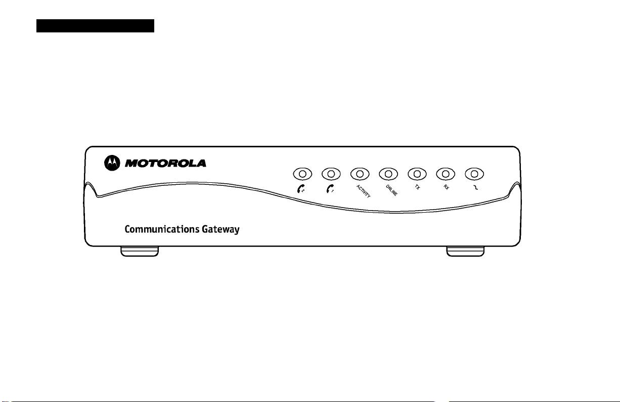
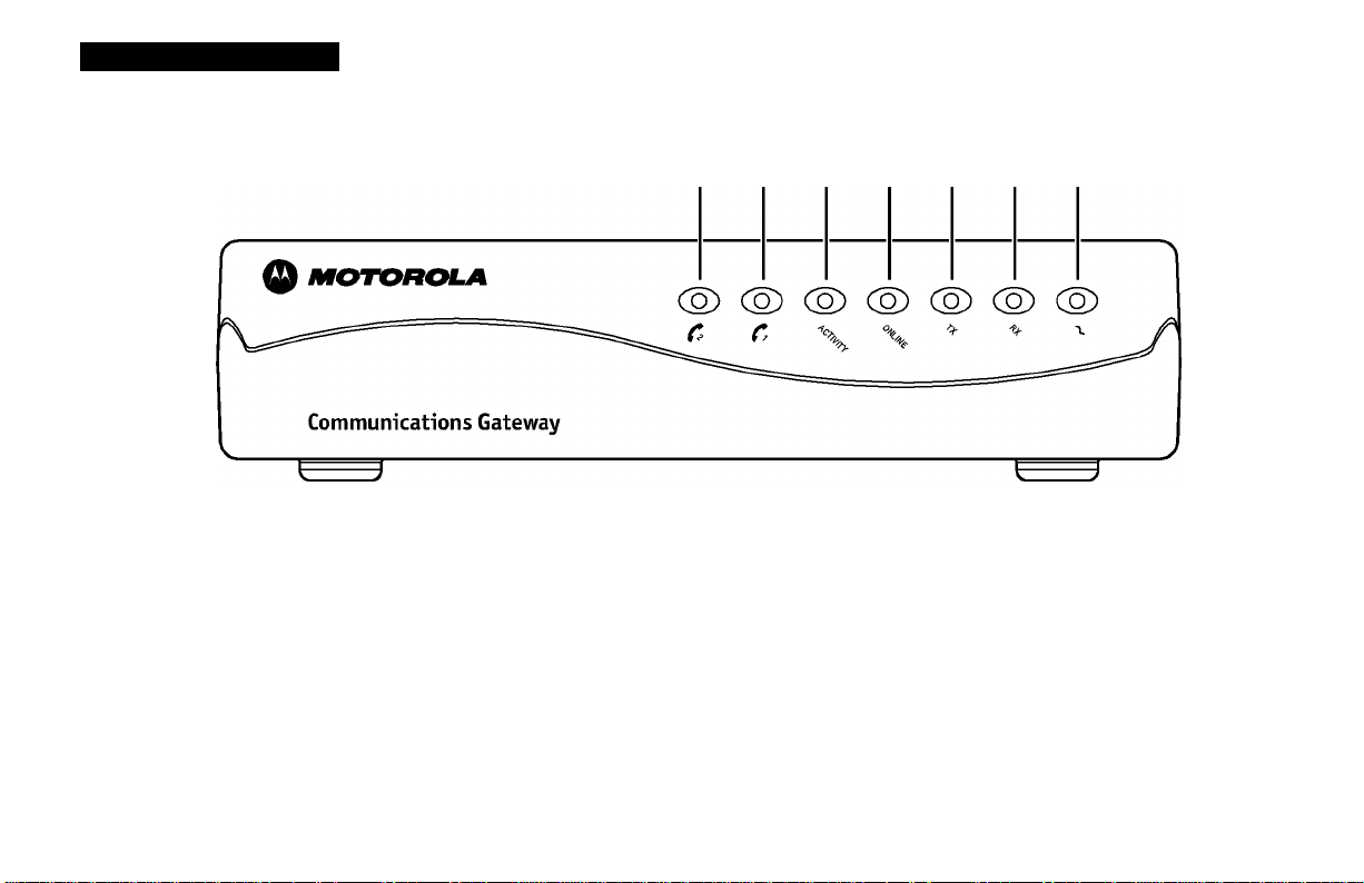
Front Panel
7 6 5 4 3 2 1
3
Page 9

INTRODUCTION
Front Panel
The seven front-panel LEDs provide information about power, communications, and errors.
LED Color Description
N
\ Green
When the LED is blinking, startup diagnostics are being performed. A solid LED indicates the CG4500 is
on and diagnostics completed successfully.
2 ^ Green
3 ^ Green
4^ Green
%
When the LED is blinking, the CG4500 is scanning for the downstream frequency and the USB and
Ethernet ports are disabled. A solid LED indicates the downstream channel is acquired and USB and
Ethernet ports are enabled. When the LED is off and other conditions apply, the CG4500 can be in the
Internet security lock mode. Refer to the rear panel section of this manual for the
Internet security lock mode description.
When the LED is blinking, the CG4500 is scanning for the upstream frequency and the USB and Ethernet
ports are disabled. A solid LED indicates the upstream channel is acquired and USB and Ethernet ports
are enabled. When the LED is off and other conditions apply, the CG4500 can be in the
Internet security lock mode. Refer to the rear panel section of this manual for the
Internet security lock mode description.
When the LED is blinking, the CG4500 is scanning for the network connection by requesting an IP
address (DHCP), downloading the configuration file (TFTP), and obtaining network time (TOD). A solid
LED indicates the CG4500 has completed the network connection and established Power, Receive, and
Send function. When the LED is blinking and other conditions apply, the Internet security lock feature
can be active. Refer to the rear panel section for the Internet security lock mode description. Refer to
the rear panel section of this manual for the Internet security lock mode description
4
Page 10

INTRODUCTION
Front Panel
LED Color Description
R
6
7
Amber When the LED is blinking, the CG4500 is transmitting or receiving data. When the LED is off, the
CG4500 is not transferring data.
Amber A solid LED indicates that phone line N is active. The phone line is inactive when the LED is not lit.
Amber A solid LED indicates that phone line O is active. The phone line is inactive when the LED is not lit.
If an error occurs, the LEDs can provide a quick way of detecting the problem. See Troubleshooting for more information.
Page 11
INTRODUCTION
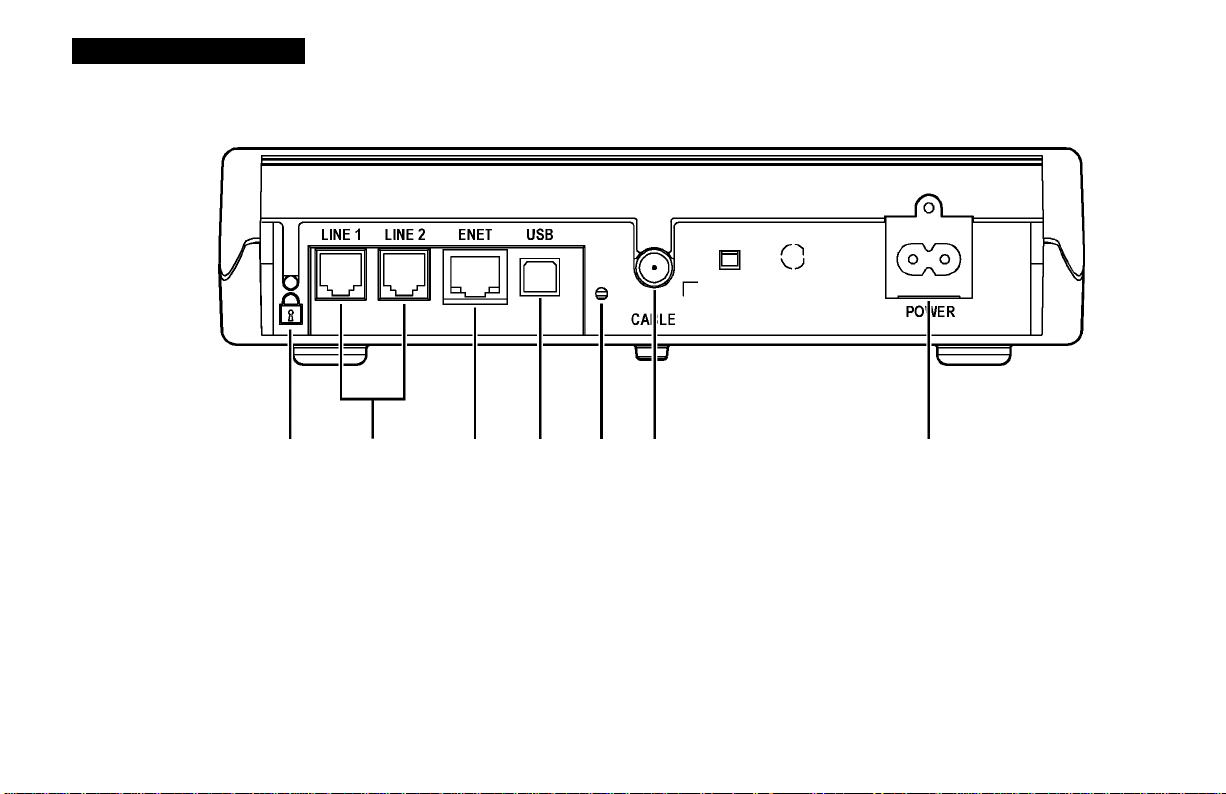
Rear Panel
3 4 5 6
7
6
Page 12

INTRODUCTION
Rear Panel
The rear panel provides Ethernet activity and link status lights, the reset button, the Internet SECURITY LOCK button
and all the connectors.
Item Description
1
O
0
LINE 1 LINE 2
1
nn
ENET
3
Press the Internet security lock button to disable the Ethernet and USB ports (not receiving or
transmitting data). The following front panel conditions occur when Internet security lock is active:
• online (Q) led is blinking
• ox (O) led is not lit
• TX (3) led is not lit
When the Internet security lock feature is active telephone service remains active and the cable
connection to the service provider remains active. When the CG4500 Internet connection is not in use,
press the Internet security lock button. This activates Internet security lock and disables the Internet
cable connection for increased security.
These RJ-llports transfer data to and from analog phone lines. Linel and Line O support single line phones.
This RJ-45 port transfers Ethernet data to and from your computer. The port contains integrated green
LEDs on the lower left and right of the port. When the lower-left LED is blinking, the Ethernet port is
transferring data. When the lower-right LED lights continuously, the Ethernet data transfer rate is
100BaseT. When the lower-right LED is not lit, the Ethernet data transfer rate is lOBaseT.
Page 13

INTRODUCTION
Rear Panel
Item Description
4 USB
This port provides a direct connection to USB equipped computers for data transfer.
5 ©
6
This push-button switch resets CG4500 power.
This F-type port provides RF connectivity to and from your service provider.
CABLE
This connector provides power to the CG4500.
8
Page 14

BEFORE YOU BEGIN
Before you begin the installation, check that you received:
One 10/100 BaseT Ethernet
cable (shielded)
These items are supplied by the service provider and are required for connecting your computer
to the CG4500.
or
One USB cable
Power cord
CG4S00 User Guide CD-ROM
You need to purchase a 75-ohm coaxial cable with F-type connectors for connecting to the nearest cable outlet. If you have a TV set attached
to the cable outlet, you may need a 5-900 MHz splitter to use both the TV and the CG4500.
Required for connecting the CG4500 to an electrical outlet.
Contains USB port connection drivers. This CD-ROM is required for connecting a USB-equipped
computer to the CG4500.
9
Page 15

BEFORE YOU BEGIN
To use all the features of the CG4500, you will need the following:
NOTE
The Ethernet card must be installed before the
CG4500. If it isn’t, follow the installation
instructions that came with your Ethernet card.
Telephone(s)
with standard
RJ-11 connectors
Service Provider
Computer
Ethernet card or
USB software
Required to use the telephony features of the CG4500.
You must sign up with a data service provider who provides
access to the Internet and other online services.
Your computer must support Ethernet or USB and the
TCP/IP protocol to access the CG4500. The CG4500 is
compatible with Microsoft®, Macintosh®, and UNIX®
operating systems. You don’t need special software to
operate the CG4500.
Any standard 10/100 Base-T Ethernet card operates with the
CG4500. The card is not required when connecting to the
USB port. The Ethernet card must be installed before the
CG4500. If it is not, follow the installation instructions
included with your Ethernet card.
The USB connection supported by Windows 98 SE,
Windows 2000, Windows Me, and Windows XP requires
special software to operate. All USB drivers are contained
on the CD-ROM supplied with your CG4500.
Your computer must be configured for TCP/IP and have an
IP address for the CG4500 to operate. Your Internet service
provider furnishes the IP address.
10
Page 16

BEFORE YOU BEGIN
NOTE
The Ethernet card must be installed before the
CG4500. If it isn’t, follow the installation
instructions that came with your Ethernet card.
HTML Browser
Any standard HTML (web) browser works with the
CG4500.
11
Page 17

INSTALLATION
The installation of the CG4500 can be completed in a matter of minutes. After you attach the cables, you must configure your
computer.
The CG4500 installation steps must be performed in the order shown in the following pages.
For ~ Single User
N Connect the coaxial cable to a cable outlet in your home. Connect the other end to the CG4500 connector marked CABLE,
as shown below. Hand-tighten the connectors to avoid damaging them.
LINE 1 LINE 2 ENET USB
ooan.
yig5=i3=o=M=Lg:
To USB jack on computer
To Ethernet jack on computer
To single-line telephone
To single-line telephone
(S®
To cable outlet or splitter
\
To electrical outlet
or
12
Page 18

INSTALLATION
CAUTION!
Do not connect Ethernet and USB cables to the same computer at the same time.
If you already have a TV connected to the cable outlet, you will need to use a 5-900 MHz splitter. Connect the coaxial cable as
shown below:
To phone
To Ethernet jack
on computer
or
To USB jack
on computer
To electrical outlet
_ 5-900 MHz ,,,
ToTV
splitter
Tocabe
outlet
13
Page 19

INSTALLATION
2 Insert the Motorola Communications Gateway CD-ROM into your CD-ROM drive.
3 Connect the 10/100 Base-T Ethernet cable to the CG4500 connector marked ENET and the other end to the Ethernet jack
on the back of your computer
Or
Connect the USB cable to the CG4500 connector marked USB and the other end to the USB jack on the back of your
computer.
4 Connect your telephone to the CG4500 connector marked LINE I. A separate phone line can be connected to the CG4500
connector marked LINE 2.
The recommended cable length for telephony port connections is 3 meters or less. The CG4500 electrically supports cable
lengths of up to 300 meters.
R Connect the power cord to the CG4500 connector marked POWER and the other end to your electrical outlet.
NOTE
If you place your Communications Gateway close to a cordless or wireless device, interference may occur when using the
telephone. If you experience interference, move the cordless or wireless device away from the Communications Gateway until you
no longer hear the noise.
Do not block the air vents by stacking equipment or other objects on top of the Communications Gateway.
14
Page 20

INSTALLATION
Powering Up the First Time
NOTE
To turn on your CG4500, simply plug it in. It is
not necessary to unplug it when not in use.
You must allow 5 to 30 minutes to power up the first time because the CG4500
must find and lock on the appropriate channels for communications.
Be sure that your computer is on, the Motorola Communications Gateway
CD-ROM is in the CD-ROM drive and has been read, and the CG4500 is
unplugged.
Plug the CG4500 power cord into your electrical outlet. Notice that the
LEDs on the front panel cycle through this sequence:
• Power blinks during a self-test. When the self-test is successfully
completed, the light is solid green.
• RX blinks while the CG4500 scans for the downstream channel. When
the downstream channel is locked, the LED is solid green.
• TX blinks while the CG4500 scans for the upstream channel. When
the upstream channel is locked, the LED is solid green.
• ONLINE blinks while the CG4500 is obtaining configuration
information. When the configuration information is obtained, the LED
is solid green.
During normal operation, the Power, RX, TX, and ONLINE LEDs are on and the
Activity LED blinks.
15
Page 21

INSTALLATION
Using the Optional Cradle
The CG4500 may come with an optional cradle that enables the modem to stand
vertically on a flat surface, such as a desktop. To use the cradle, insert the modem
into the cradle until the modem’s feet fully engage with the grooves.
16
Page 22

INSTALLATION
For Multiple Users
17
Page 23

INSTALLATION
For Multiple Users
Multiple user configurations can include Ethernet and USB connections.
Ethernet and USB
For single users on individual computers, connect the USB and Ethernet ports
directly to the CG4500.
CAUTION!
Do not connect Ethernet and USB cables to the same
computer at the same time.
18
Page 24

INSTALLATION
For Multiple Users
19
Page 25

BASIC CONFIGURATION
The CG4500 contains all necessary software. You don’t need to configure the
CG4500, but you must configure your computer for TGP/IP and check for an IP
address. Your service provider may provide additional instructions for setting up
your computer. The following basic instructions are for Windows 95 or
Windows 98. Use Microsoft online help to install and configure hardware for
Windows 2000 and Windows Me. If you are using a different operating system, refer
to that user guide.
Configuring for TCP/IP
N On the Windows Desktop, click Start.
2 Select Settings and then Control Panel from the pop-up menus.
3 Double-click the Network icon on the Control Panel window.
4 Select the Configuration tab on the Network window.
R Check to see if TCP/IP has been installed for the Ethernet or USB
card. If TCP/IP appears in the list of network components, it is
installed and you can proceed to step 10. If it doesn’t appear on the
list, continue with step 6.
20
Page 26

BASIC CONFIGURATION
6 Click Add.
^ Double-click the Protocol option on Select Network Component
Type window.
8 Click Microsoft in the Manufacturers section and then click TCP/IP in
the Network Protocol section of Select Network Protocol window.
V Click OK.
21
Page 27

BASIC CONFIGURATION
10 Click TCP/IP on the Network window. If you have more than one
TCP/IP entry, choose the one associated with the Ethernet or USB
card connected to the CG4500.
11 Click Properties.
12 Select the IP Address tab on the TCP/IP window.
13 Click Obtain an IP address automatically.
14 Click OK to accept the TCP/IP settings.
1R Click OK to close the Network window.
16 Click OK when a prompt to restart your computer is displayed and
then click OK again.
22
Page 28

BASIC CONFIGURATION
Installing USB Device Drivers
The USB drivers can interface with Windows 98 SE, 2000, Me, or XP. The Motorola Communications Gateway USB driver does not
support Macintosh or UNIX computers. You can connect a Macintosh or UNIX system using an Ethernet card only.
Be sure the Motorola Communications Gateway CD-ROM is inserted in your CD-ROM drive before you plug in the USB cable. This CD
contains the USB drivers and must be inserted and read by the PC before you connect the Communications Gateway to the PC.
System files are needed when loading the USB drivers. These files may already be on your PC or you may be required to load them
from the Microsoft CD that came with your PC.
A few seconds after you complete the USB connection as described in “Installation for a Single User,” the Add New Hardware
Wizard window is displayed.
N Click CD-ROM drive option and specify a location.
2 Click Browse.
3 Select your CD-ROM drives. USB drivers. Example: D: USB DEVICE DRIVERS
4 Click Next to load the USB drivers.
R Click Next to install the driver on the location displayed.
6 Insert your Microsoft Operating System CD when prompted, if the operating system is not installed on the hard drive.
Or
Click next at the prompt, if the operating system is loaded on the hard drive.
^ Click Yes to restart your computer and finish setting up the new hardware.
23
Page 29

BASIC CONFIGURATION
Verifying Your IP Address
The following basic instructions are for Windows 95 or Windows 98. If you are using
a different operating system, refer to that user guide. To check the IP address:
N On the Windows Desktop, click Start.
2 Select Run.
3 Type winipcfg.exe. A window similar to the example is displayed.
4 Select your adapter name.
R Click Renew.
6 Click OK after the system displays an IP address.
If after performing this procedure, your computer doesn’t access the internet, call
your service provider. They will assist in verifying your configuration.
24
Page 30

TROUBLESHOOTING
This information is to help you quickly solve a problem. Before calling your service provider, try pressing the reset button. Resetting
the CG4500 may take 5 to 30 minutes. Your service provider will need to know the status of the front-panel lights in order to assist
you.
The problem
Green POWER LED is off Check that the power cord is properly plugged into the wall outlet and to the rear panel of the CG4500.
Cannot receive or send data Check the LEDs on the front-panel. Front-panel LED descriptions are oriented 45° so that they can be
Possible Solution
Call your service provider.
read in vertical or horizontal positions.
Place the unit on a flat table-top and read the LEDs left to right.
Or
Place the unit in its optional cradle and read the LEDs top to bottom.
Identify the first LED from top to bottom or right to left that is off. This LED indicates where the error
occurred. If the first LED that is off is:
RX
TX
During normal operation, the downstream channel is lost. During startup, the downstream
channel is not acquired.
During normal operation, the upstream channel is lost. During startup, the upstream
channel is not acquired.
ONLINE During normal operations, the IP registration is lost. During startup, the IP registration was
not successful.
25
Page 31

TROUBLESHOOTING
Check that your TV is working, that you have cable TV, and that you have a clear TV picture. If you
aren’t receiving your regular TV channels, your data service will not function.
Check the coaxial cable at the rear panel and outlet and hand-tighten if necessary.
Check the IP address (follow the steps on page 24); call your service provider if you need an IP address.
Check that Internet security lock is not active. The Internet security lock feature is active when the
following conditions occur:
• ONLINE (4) LED is blinking
• ox (2) LED is not lit
• TX (3) LED is not lit.
Press the Internet security lock button to deactivate Internet security lock and restore your
Internet cable connection.
When the CG4500 Internet connection is not in use, press the Internet security lock button. This
activates Internet security lock and disables the Internet cable connection for increased security.
16
Page 32

SOFTWARE LICENSE AND WARRANTY INFORMATION
TELEPHONY COMMUNICATIONS GATEWAY
Motorola, Inc., Broadband Communications Sector (“Motorola”)
Cable Data/Telephony Division
101 Tournament Drive
Horsham, PA 19044
IMPORTANT: PLEASE READ THIS SOFTWARE LICENSE (“LICENSE”) CAREFULLY BEFORE YOU INSTALL, DOWNLOAD OR
USE ANY APPLICATION SOFTWARE, USB DRIVER SOFTWARE, FIRMWARE AND RELATED DOCUMENTATION
(“SOFTWARE”) PROVIDED WITH MOTOROLA’S TELEPHONY COMMUNICATIONS GATEWAY PRODUCT (THE “CG
PRODUCT”). BY USING THE CG PRODUCT AND/OR INSTALLING, DOWNLOADING OR USING ANY OF THE
SOFTWARE, YOU INDICATE YOUR ACCEPTANCE OF EACH OF THE TERMS OF THIS LICENSE. UPON ACCEPTANCE, THIS
LICENSE WILL BE A LEGALLY BINDING AGREEMENT BETWEEN YOU AND MOTOROLA. THE TERMS OF THIS LICENSE
APPLY TO YOU AND TO ANY SUBSEQUENT USER OF THIS SOFTWARE.
IF YOU DO NOT AGREE TO ALL OF THE TERMS OF THIS LICENSE (I) DO NOT INSTALL OR USE THE SOFTWARE AND (II)
RETURN THE CG PRODUCT AND THE SOFTWARE (COLLECTIVELY, “PRODUCT”), INCLUDING ALL COMPONENTS,
DOCUMENTATION AND ANY OTHER MATERIALS PROVIDED WITH THE PRODUCT, TO YOUR SERVICE PROVIDER FOR
A FULL REFUND.
The Software includes associated media, any printed materials, and any “on-line” or electronic documentation. Software provided
by third parties may be subject to separate end-user license agreements from the manufacturers of such Software.
The Software is never sold. Motorola licenses the Software to the original customer and to any subsequent licensee for personal use
only on the terms of this License. Motorola and its 3^ party licensors retain the ownership of the Software.
Page 33

SOFTWARE LICENSE
You may:
USE the Software only in connection with the operation of the Product.
TRANSFER the Software (including all component parts and printed materials) permanently to another person, but only if the
person agrees to accept all of the terms of this License. If you transfer the Software, you must at the same time transfer the Product
and all copies of the Software (if applicable) to the same person or destroy any copies not transferred.
TERMINATE this License by destroying the original and all copies of the Software (if applicable) in whatever form.
You may not:
(I) Loan, distribute, rent, lease, give, sublicense or otherwise transfer the Software, in whole or in part, to any other person, except
as permitted under the TRANSFER paragraph above. (2) Copy or translate the User Guide included with the Software, other than
for personal use. (3) Copy, alter, translate, decompile, disassemble or reverse engineer the Software, including but not limited to,
modifying the Software to make it operate on non-compatible hardware. (4) Remove, alter or cause not to be displayed, any
copyright notices or startup message contained in the Software programs or documentation. (5) Export the Software or the Product
components in violation of any United States export laws.
The Product is not designed or intended for use in on-line control of aircraft, air traffic, aircraft navigation or aircraft
communications; or in design, construction, operation or maintenance of any nuclear facility. MOTOROLA AND ITS 3° PARTY
LICENSORS DISCLAIM ANY EXPRESS OR IMPLIED WARRANTY OF FITNESS FOR SUCH USES. YOU REPRESENT AND
WARRANT THAT YOU SHALL NOT USE THE PRODUCT FOR SUCH PURPOSES.
Title to this Software, including the ownership of all copyrights, mask work rights, patents, trademarks and all other intellectual
property rights subsisting in the foregoing, and all adaptations to and modifications of the foregoing shall at all times remain with
Motorola and its 3^ party licensors. Motorola retains all rights not expressly licensed under this License. The Software, including any
images, graphics, photographs, animation, video, audio, music and text incorporated therein is owned by Motorola or its 3^ party
licensors and is protected by United States copyright laws and international treaty provisions. Except as otherwise expressly
provided in this License, the copying, reproduction, distribution or preparation of derivative works of the Software, any portion of
Page 34

the Product or the documentation is strictly prohibited by such laws and treaty provisions. Nothing in this License constitutes a
waiver of Motorola’s rights under United States copyright law.
This License and your rights regarding any matter it addresses are governed by the laws of the Commonwealth of Pennsylvania,
without reference to conflict of laws principles. THIS LICENSE SHALL TERMINATE AUTOMATICALLY if you fail to comply with
the terms of this License.
Motorola is not responsible for any third party software provided as a bundled application, or otherwise, with the Software.
U.S. GOVERNMENT RESTRICTED RIGHTS
The Product and documentation is provided with RESTRICTED RIGHTS. The use, duplication or disclosure by the Government is
subject to restrictions as set forth in subdivision (c)(l)(ii) of The Rights in Technical Data and Computer Software clause at
52.227-7013. The contractor/manufacturer is Motorola, Inc., Broadband Communications Sector, lOl Tournament Drive, Horsham,
PA 19044.
WARRANTY INFORMATION
What is my warranty?
A limited warranty for this Product (including Software) is provided by Motorola to your distributor, cable operator or Internet
service provider, as applicable. Please contact your cable operator or internet service provider (“Service Provider”) for details.
Motorola does not warrant that any Software will perform error free or without bugs. Motorola’s warranty shall not apply: (i) to any
Product subjected to accident, misuse, neglect, alteration, Acts of God, improper handling, improper transport, improper storage,
improper use or application, improper installation, improper testing or unauthorized repair; or (ii) to cosmetic problems or defects
which result from normal wear and tear under ordinary use, and do not affect the performance or use of the Product. Motorola’s
warranty applies only to a Product that is manufactured by Motorola and identified by Motorola-owned trademark, trade name or
product identification logos affixed to the Product. MOTOROLA DOES NOT WARRANT THIS PRODUCT DIRECTLY TO YOU,
THE END USER. EXCEPT AS DESCRIBED IN THIS SECTION “WARRANTY INFORMATION”, THERE ARE NO WARRANTIES
OR REPRESENTATIONS OF ANY KIND RELATING TO THE PRODUCT, EXPRESS, IMPLIED OR STATUTORY, INCLUDING
BUT NOT LIMITED TO IMPLIED WARRANTIES OF MERCHANTABILITY, FITNESS FOR A PARTICULAR PURPOSE, OR
Page 35

WARRANTY AGAINST INFRINGEMENT. MOTOROLA IS NOT RESPONSIBLE FOR, AND PROVIDES “AS IS” ANY SOFTWARE
SUPPLIED BY 3RD PARTIES.
What additional provisions should I be aware of?
Because it is impossible for Motorola to know the purposes for which you acquired this Product or the uses to which you will put
this Product, you assume full responsibility for the selection of the Product for its installation and use. While every reasonable effort
has been made to insure that you will receive a Product that you can use and enjoy, Motorola does not warrant that the functions of
the Product will meet your requirements or that the operation of the Product will be uninterrupted or error-free. MOTOROLA IS
NOT RESPONSIBLE FOR PROBLEMS OR DAMAGE CAUSED BY THE INTERACTION OF THE PRODUCT WITH ANY OTHER
SOFTWARE OR HARDWARE.
How long does this Limited Warranty last?
Contact your Service Provider for details.
What you must do to obtain warranty service.
For Product customer service, technical support, warranty claims, questions about your internet service or connection, contact your
Service Provider. ALL WARRANTIES ARE VOID IF THE PRODUCT IS OPENED, ALTERED, AND/OR DAMAGED.
THESE ARE YOUR SOLE AND EXCLUSIVE REMEDIES FOR ANY AND ALL CLAIMS THAT YOU MAY HAVE ARISING OUT OF
OR IN CONNECTION WITH THIS PRODUCT, WHETHER MADE OR SUFFERED BY YOU OR ANOTHER PERSON AND
WHETHER BASED IN CONTRACT OR TORT.
IN NO EVENT SHALL MOTOROLA BE LIABLE TO YOU OR ANY OTHER PARTY FOR ANY DIRECT, INDIRECT, GENERAL,
SPECIAL, INCIDENTAL, CONSEQUENTIAL, EXEMPLARY OR OTHER DAMAGES ARISING OUT OF THE USE OR INABILITY
TO USE THE PRODUCT (INCLUDING, WITHOUT LIMITATION, DAMAGES FOR LOSS OF BUSINESS PROFITS, BUSINESS
INTERRUPTION, LOSS OF INFORMATION OR ANY OTHER PECUNIARY LOSS), OR FROM ANY BREACH OF WARRANTY,
EVEN IF MOTOROLA HAS BEEN ADVISED OF THE POSSIBILITY OF SUCH DAMAGES. IN NO CASE SHALL MOTOROLA’S
LIABILITY EXCEED THE AMOUNT YOU PAID FOR THE PRODUCT.
Motorola’s warranty is governed by the laws of the Commonwealth of Pennsylvania, excluding its conflict of laws principles and
excluding the provisions of the United Nations Convention on Contracts for the International Sale of Goods.
Page 36

MOTOROLA.
501431-001
HO!
English
MGBI
 Loading...