

Page 1
CG3500 Communications Gateway
User Guide
CG3500 Communications Gateway
LINE 2
L
INE 1
A
CT
ONLINE
I
VIT
Y
SEN
REC
D
POWER
EI
VE
Page 2
REGULATORY INFORMAT ION
CAUTION
RISK OF ELECTRIC SHOCK
TO REDUCE THE RISK OF ELECTRIC SHOCK,
CAUTION:
DO NOT REMOVE COVER (OR BACK).
NO USER-SERVICEABLE PARTS INSIDE.
REFER SERVICING TO QUALIFIED SERVICE PERSONNEL.
CAUTION
These servicing instructions are for use by qualified personnel only. To reduce the risk
of electrical shock, do not perform any s ervicing other than that contained in the
Installation and Troubleshooting Instructions unless you are qualified to do so. Refer all
servicing to qualified service personnel.
Special Symbols th at Might Appear on the Eq
Special Symbols th at Might Appear on the Equipment
Special Symbols th at Might Appear on the EqSpecial Symbols th at Might Appear on the Eq
Different types of cord sets may be used for connections
to the main supply circuit. Use only a main line cord that
complies with all applicable product safety requirements
of the country of use.
The exclamation point, within an equilateral triangle, is
intended to alert the user to the presence of important
installation, servicing, and operating instructions in the
documents accompanying the equipment.
uipment
uipmentuipment
TO PREVENT FIRE OR SHOCK HAZARD, DO NOT EXPOSE THIS APPLIANCE TO
WARNING
RAIN OR MOISTURE.
CAUTION
USE ONLY MAINS LINE CORD THAT COMPLIES WITH THE COUNTRY’S
PRODUCT SAFETY REQUIREMENTS.
Page 3

Declaration of Conformity
We
of: 3850 North Wilkes Road
and: Imperium
declare that the product:
Communications Gateway CG3500
to which this declaration relates, is in compliance with the following:
The product having been evaluated against the following Standards:
and further it is declared to be in compliance with the following:
The product having been evaluated against the following Standards:
Motorola, Inc.
Broadband Communication Sector
Arlington Heights, Illinois 60004-1271
Imperial Way
Reading Berkshire, England
United Kingdom
Council Directive 89/336/ECC (EMC Directive) as
amended by:
Council Directive 93/68/ECC, Article 5
Council Directive 92/31/EEC
EN 50082-1: 1992
EN 55022: 1994 + A1: 1995 + A2: 1997 / CISPR 22: 1993
EN 61000-3-2: 1995 + A1: 1998 + A2: 1998
EN 61000-3-3: 1995
Council Directive 73/23/ECC (Low Voltage Directive) as
amended by:
93/68/EEC, Article 13
EN 60950: 1992 + A1: 1993 + A2: 1993 + A3: 1995 + A4: 1997
+ A11: 1997/
IEC 950: 1991 + A1: 1992 + A2: 1993 + A3: 1995 + A4: 1996
Repairs
If repair is necessary, contact your cable modem service provider.
Copyright © 2001 by Motorola, Inc.
All rights reserved. No part of this publication may be reproduced in any form or by any
means or used to make any derivative work (such as translation, transformation or
adaptation) without written permission from Motorola, Inc.
Motorola, Inc. reserves the right to revise this publication and to make changes in
content from time to time without obligation on the part of Motorola, Inc. to provide
notification of such revision or change. Motorola, Inc. provides this guide without
warranty of any kind, either implied or expressed, including, but not limited, to the
implied warranties of merchantability and fitness for a particular purpose. Motorola, Inc.
may make improvements or changes in the product(s) described in this manual at any
time.
MOTOROLA and the stylized M logo are registered trademarks of Motorola, Inc.
Macintosh is a registered trademark of Apple Corporation.
Microsoft, Windows, Windows 95 and Windows 98 are registered trademarks of
Microsoft Corporation.
Netscape is a registered trademark of Netscape Communications Corporation.
UNIX is a registered trademark of the Open Group.
Page 4

CONTENTS
Introduction-------------------------------------------------1
Front Panel-------------------------------------------------2
Rear Panel--------------------------------------------------4
Before You Begin------------------------------------------6
Installation---------------------------------------------------8
For a Single User------------------------------------------8
Connecting the Power Supply------------------------ 10
Powering Up the First Time -------------------------- 11
Using the Optional Cradle-----------------------------12
For Multiple Users --------------------------------------13
Basic Configuration------------------------------------- 14
Configuring for TCP/IP---------------------------------14
Verifying Your IP Address -----------------------------17
Troubleshooting----------------------------------------- 18
Page 5
INTRODUCTION
The Motorola CG3500 Communications Gateway cable modem enables you to connect your home or business computer to a
high-speed Data Over Cable Service Interface Specification (DOCSIS) 1.0 or 1.1 compliant data network. The CG3500 provides
high-speed, bi-directional data access with Radio Frequency (RF) downstream transfer rates up to 38 Mbps and RF upstream
rates up to 10 Mbps. It also provides telephony voice communication features using the Internet Protocol (IP) known as Voice
over IP (VoIP).
Unlike a dial-up modem, the CG3500 is always online. Just open your browser and surf.
CG3500 Communications Gateway
L
I
L
N
I
E
2
ACTI
NE 1
O
N
V
ITY
SEN
L
I
N
E
RECEIVE
D
PO
W
ER
1
Page 6
INTRODUCTION
Front Panel
7
65
4
3
21
CG3500 Communications Gateway
LINE 2
L
INE 1
A
CT
ONLINE
I
VIT
Y
SEND
R
E
POWER
C
EI
VE
2
Page 7

INTRODUCTION
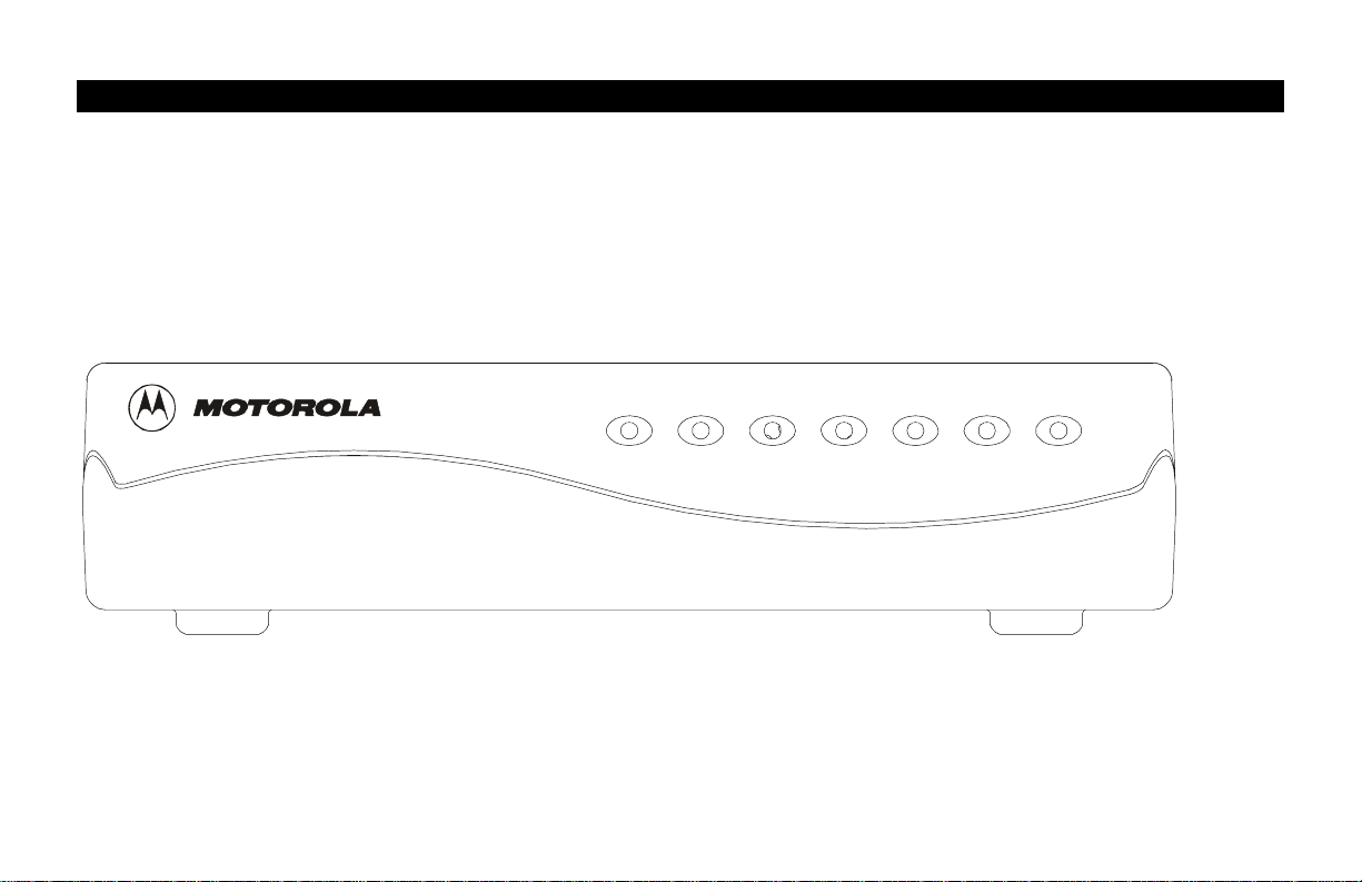
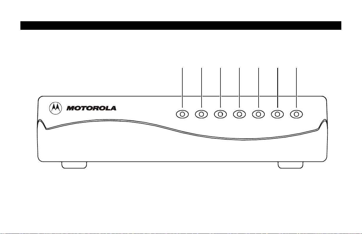
Front Panel
The seven front panel lights provide information about power, communications, and errors.
Light Color Description
1
2
3
4
5
6
7
Power
Receive
Send
Online
Activity
Line 1
Line 2
Green When the light is flashing, startup diagnostics are being performed. A solid light indicates the CG3500
is on.
Green When the light is flashing, the CG3500 is scanning for the downstream frequency. A solid light
indicates the downstream channel is acquired.
Green When the light is flashing, t he CG3500 is scanning for the upstream frequency. A solid light indicates
the upstream channel is acquired.
Green When the light is flashing, the CG3500 is scanning for the network connection. A solid light indicates
the network connection is acquired.
Amber When the light is flashing, the CG3500 is transmitting or receiving data. When the light is off, the
CG3500 is not transferring data.
Amber A solid amber light indicates that telephone line 1 is active.
Amber A solid amber light indicates that telephone line 2 is active.
If an error occurs, the lights provide a quick way of detecting the problem. See Troubleshooting for
more information.
3
Page 8
INTRODUCTION
Rear Panel
LINE 2 LINE 1
ENET
POWER
CABLE
12 4536 7
MODEL: CG3500 C ommunicati ons Gateway
P/N: 480473-001
CUST S/N: BCDFGHJKLMNP
S/N: PPPPMMYJJJSSSSSCKAABBCCCC
HFC MAC ID: ABCDEF012345
Made in Taiwan, R. O. C.
4
Page 9

INTRODUCTION
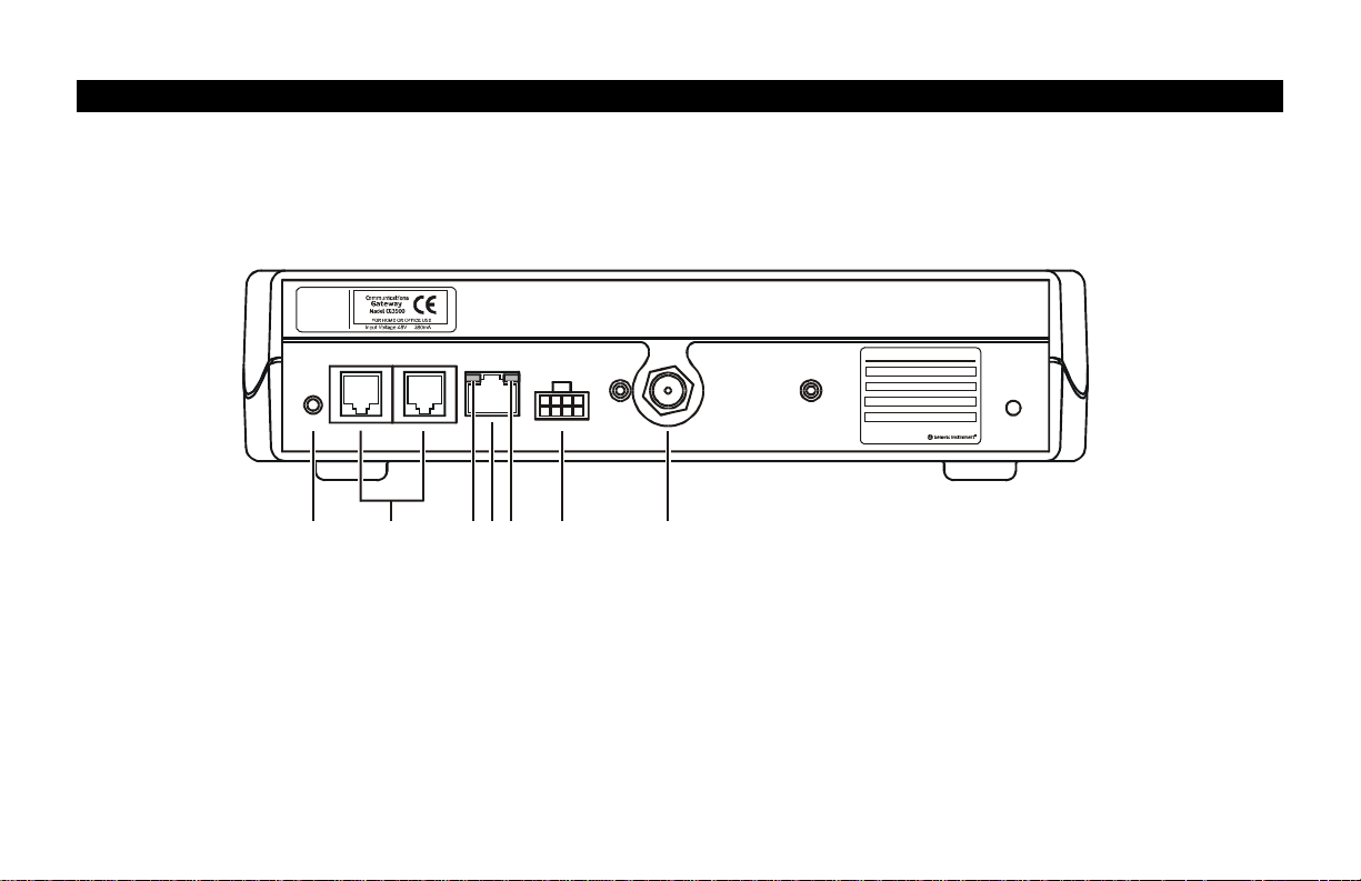
Rear Panel
The rear panel provides Ethernet activity and link status lights, the reset button, and all the connectors.
Item Description
1
2
3
4
5
6
7
LINE 2
ENET
POWER
CABLE
This is the recessed reset button.
These ports transfer data to and from analog phone lines. They are RJ-11 connectors.
When this yellow light flas hes, the Ethernet connection is transferring data.
This port transfers data to and from your computer. This is an RJ-45 connector.
When this green light is on, t he Ethernet connection is available.
This connector provides power to the CG3500.
This port provides RF connectivity to and from your service provider. This is an F-type connector.
5
Page 10

BEFORE YOU BEGIN
Before you begin the installation, check that you received:
One 10Base-T Ethernet cable
Required to connect your computer to the CG3500.
Power supply and cable
The CG3500 is powered by an Uninterruptible Power Supply (UPS)
You need to purchase a 75-ohm coaxial cable with F-type connectors for connecting to the nearest cable outlet. If you have a
TV set attached to the cable outlet, you may need a 5-900 MHz splitter to use both the TV and the CG3500.
6
Page 11

BEFORE YOU BEGIN
NOTE
The Ethernet card must be installed before the
CG3500. If it isn’t, follow the installation
instructions that came with your Ethernet card.
To use all the features of the CG3500, you will need the following:
Telephone(s)
with standard
RJ-11 connectors
Service Provider
Computer
Ethernet card
HTML Browser
Required to use the telephony features of the CG3500.
You must sign up with a data service provider who provides
access to the Internet and other online services.
Your computer must support Ethernet and the TCP/I P
protocol to access the CG3500. The CG3500 is compatible
with Microsoft
You don’t need special software to operate the CG3500.
Any standard 10Base-T Ethernet card operates with the
CG3500. Your computer must be configured for TCP/IP and
have an IP address for the CG3500 to operate. Your
Internet service provider furnishes the IP address.
Any standard HTML (web) browser works with the
CG3500.
®
, Macintosh®, and UNIX® operating systems.
7
Page 12

INSTALLATION
The installation of the CG3500 can be completed in a matter of minutes. After you attach the cables, you must configure your
computer.
The CG3500 installation steps must be performed in the order shown in the following pages.
For a Single User
1 Connect the coaxial cable to a cable outlet in your home. Connect the other end to the CG3500 connector marked CABLE,
as shown below. Hand-tighten the connectors to avoid damaging them.
LINE 2 LINE 1
Ferrite
ENET
POWER
CABLE
MODEL: CG3500 Communications Gateway
P/N: 480473-001
CUST S/N: BCDFG HJKLMNP
S/N: PPPPMMYJJJSSSSSCKAABBCCCC
HFC MAC ID: ABCDEF012345
Made i n Taiwa n, R. O. C.
To cable outlet or splitter
To UPS
T o E th e rnet jack on comp uter
To telephone
8
Page 13

INSTALLATION
If you already have a TV connected to the cable outlet, you will need to use a 5-900 MHz splitter. Connect the coaxial cable as
shown below:
LINE 2 LINE 1
ENET
POWER
CABLE
To TV
MODEL: CG3500 Communications Ga teway
P/N: 480473-001
CUST S/N: BCDFG HJKLMNP
S/N: PPPPMMYJJJSSSSSC KAABBCCCC
HFC MAC ID: ABCDEF012 3 45
Made in Taiwan, R. O. C.
5-900
MHz
splitter
To cable
outlet
2 Connect the 10Base-T Ethernet cable to the CG3500 connector marked ENET and the other end to the Ethernet jack on the
back of your computer.
3 Connect your telephone to the CG3500 connector marked LINE 1. A separate phone line can be connected to the CG3500
connector marked
LINE 2. Each line connector on the CG3500 supports up to five telephones (one REN per telephone).
4 Connect the UPS cable to the CG3500 connector marked POWER as shown in the following sections.
9
Page 14

INSTALLATION
Connecting the Power Supply
Prepare the UPS according to the manufacturer’s instructions. You must use the cable provided with the CG3500 to connect the UPS to
the CG3500. Do not substitute another cable.
Do not connect the battery until you have connected the UPS to the CG3500.
1 Connect the UPS to the CG3500 connector marked POWER.
2 Connect the battery to the UPS per the manufacturer’s instructions.
UPS
LINE 2 LINE 1
Power
ENET
POWER
CABLE
MODEL: CG3500 Communications Gateway
P/N: 480473-001
CUST S/N: BCDFGHJKLMNP
S/N: PPPPMMYJJJSSSSSCKAABBCCCC
HFC MAC ID: ABCDEF012345
Made in Taiwa n, R. O. C.
10
Page 15

INSTALLATION
NOTE
To turn on your CG3500, simply plug it in. It is
not necessary to unplug it when not in use.
Powering Up the First Time
You must allow 5 to 30 minutes to power up the first time because the
CG3500 must find and lock on the appropriate channels for communications.
1 Be sure that your computer is on and that the CG3500 is unplugged.
2 Plug in the AC power cord for the external UPS. Notice that the lights
on the front panel cycle through this sequence:
• Power flashes during a self-test. When the self-test is
successfully complete, the light is solid green.
• Receive flashes while the CG3500 scans for the downstream
channel. When the downstream channel is locked, the light is
solid green.
• Send flashes while the CG3500 scans for the upstream channel.
When the upstream channel is locked, the LED is solid green.
• Online flashes while the CG3500 is obtaining configuration
information. When the configuration information is obtained,
the LED is solid green.
During normal operation, the Power, Receive, Send, and Online lights are on
and the Activity light flashes.
11
Page 16

INSTALLATION
Using the Optional Cradle
The CG3500 may come with an optional cradle that enables the modem to
stand vertically on a flat surface, such as a desktop. To use the cradle, insert
the modem into the cradle until the modem’s feet fully engage with the
grooves.
CG3500 Communications Gateway
12
Page 17

INSTALLATION
Service
provider
TV cable
CG3500
Crossover
Ethernet connection
Ethernet
hub
Standard
Ethernet cable
Com puter Com puter
Com puter
For Multiple Users
The CG3500 can easily serve as a gateway to the Internet for up to 32 users.
The users must be on the same Local Area Network (LAN), and the
CG3500 must be attached to the LAN and the cable system.
The network administrator at your service provider configures
your modem for multiple users.
13
Page 18

BASIC CONFIGURATION
The CG3500 contains all necessary software. You don’t need to configure
the CG3500, but you must configure your computer for TCP/IP and check
for an IP address. Your service provider may provide additional instructions
for setting up your computer. The following basic instructions are for
Windows™ 95 or Windows 98. If you are using a different operating
system, refer to that user guide.
Configuring for TCP/IP
On the Windows Desktop, click Start.
1
2 Select Settings and then Control Panel from the pop-up menus.
3 Double-click the Network icon on the Control Panel window.
4 Select the Configuration tab on the Network window.
5 Check to see if TCP/IP has been installed for the Ethernet card. If
TCP/IP appears in the list of network components, it is installed and
you can proceed to step 10. If it doesn’t appear on the list, continue
with step 6.
14
Page 19

BASIC CONFIGURATION
6 Click Add.
7 Double-click the Protocol option on Select Network Component
Type window.
8 Click Microsoft in the Manufacturers section and then click TCP/IP in
the Network Protocol section of Select Network Protocol window.
9 Click OK.
15
Page 20

BASIC CONFIGURATION
10 Click TCP/IP on the Network window. If you have more than one
TCP/IP entry, choose the one associated with the Ethernet card
connected to the CG3500.
11 Click Properties.
12 Select the IP Address tab on the TCP/IP window.
13 Click Obtain an IP address automatically.
14 Click OK to accept the TCP/IP settings.
15 Click OK to close the Network window.
16 Click OK when a prompt to restart your computer is displayed and
then click OK again.
16
Page 21

BASIC CONFIGURATION
Verifying Your IP Address
The following basic instructions are for Windows 95 or Windows 98. If you
are using a different operating system, refer to that user gui de. To check the
IP address:
1 On the Windows Desktop, click Start.
2 Select Run.
3 Type winipcfg.exe. A window similar to the example is displayed.
4 Select your adapter name.
5 Click Renew.
6 Click OK after the system displays an IP address.
If after performing this procedure, your computer doesn’t access the
internet, call your service provider. They will assist in verifying your
configuration.
17
Page 22

TROUBLESHOOTING
This information is to help you quickly solve a problem. Before calling your service provider, try pressing the reset button. Resetting
the CG3500 may take 5 to 30 minutes. Your service provider will need to know the status of the front-panel lights.
The problem Possible Solution
Green POWER light is off
Cannot receive or send data
Check that the power cord is properly plugged into the wall outlet and to the rear panel of the CG3500.
Call your service provider.
Check the lights on the front-panel. Note the first light from top to bottom that is off. This light
indicates where the error occurred. If the first light that is off is:
Receive
Send
Online
Check that your TV is working, that you have cable TV, and that you have a clear TV picture. If you
aren’t receiving your regular TV channels, your data service will not funct ion.
Check the coaxial cable at the rear panel and outlet and hand-tighten if necessary.
Check the IP address (follow the steps on page 17); call your service provider if you need an IP address.
During normal operation, the downstream channel is lost. During startup, the downstream
channel is not acquired.
During normal operation, the upstream channel is lost. During startup, the upstream
channel is not acquired.
During normal operations, the IP registration is lost. During startup, the IP registration was
not successful.
18
Page 23

TROUBLESHOOTING
The CG3500 has two major functional blocks — cable modem and telephony — as illustrated in the following block diagram:
Cable modem
Network
management
agent
IP
processing
Power
supply
Enet
Power
Cable
Tuner/RF
Telephony
Downstream
receiver
Upstream
transmitter
MAC
CODEC DSP
Subscriber
line
interface
Line 1 Line 2
Subscriber
line
interface
Call signalling
Voice
management
19
Page 24

SOFTWARE LICENSE
IMPORTANT: PLEASE READ THIS SOFTWARE LICENSE AGREEMENT
(“AGREEMENT”) CAREFULLY BEFORE YOU OPEN THE PRODUCT PACKAGE
AND USE THE PRODUCT. BY OPENING THE PRODUCT PACKAGE AND USING
THE PRODUCT YOU INDICATE YOUR ACCEPTANCE OF EACH OF THE TERMS
OF THIS AGREEMENT AND AGREE TO BE BOUND BY THE TERMS OF THIS
AGREEMENT. UPON ACCEPTANCE, THIS AGREEMENT WILL BE A LEGALLY
BINDING AGREEMENT BETWEEN YOU AND MOTOROLA BCS. THE TERMS OF
THIS AGREEMENT APPLY TO YOU AND TO ANY SUBSEQUENT LICENSEE OF
THIS PRODUCT. IF YOU DO NOT AGREE TO ALL OF THE TERMS OF THIS
AGREEMENT:
DO NOT INSTALL OR USE THE PRODUCT, ITS SOFTWARE, COMPONENTS,
DOCUMENTATION OR ANY OTHER CONTENTS OF THE PRODUCT PACKAGE.
RETURN THIS PRODUCT INCLUDING ALL SOFTWARE, COMPONENTS,
DOCUMENTATION OR ANY OTHER CONTENTS OF THE PRODUCT PACKAGE,
TOGETHER WITH PROOF OF PURCHASE OF THIS PRODUCT, TO PLACE OF
PURCHASE WITHIN TEN (10) DAYS AFTER PURCHASE, FOR A FULL REFUND.
YOU SHOULD OPEN THIS PRODUCT PACKAGE AND USE THE PRODUCT ONLY
IF YOU ACCEPT EACH OF THE TERMS OF THIS AGREEMENT.
Any and all firmware and/or software accompanying the Motorola BCS Cable Modem
(collectively “Software”) is never sold. Motorola BCS licenses the Software to the
original customer and to any subsequent licensee for personal use only on the terms of
this Agreement. Motorola BCS retains the ownership of the Software. BY OPENING
THIS PRODUCT PACKAGE AND USING THE PRODUCT YOU INDICATE YOUR
ACCEPTANCE OF THESE TERMS. Otherwise, you may return the Product (including
all Software, components, documentation, and other contents of this Product package)
together with proof of purchase, within ten (10) days after purchase, to th e place where
you obtained it for a full refund. The Software is licensed to you under the following
terms.
Page 25

You may
USE the Software only in connection with the operation of the Motorola BCS Cable
Modem provided with this package.
TRANSFER the Software and this license (including all component parts and printed
materials) permanently to another person, but only if the person agrees to accept all of
the terms of this License. If you transfer the Software, you must at the same time either
transfer all copies of the Software (if applicable) to the same perso n or destroy any
copies not transferred.
TERMINATE this License by destroying the original and all copies of the Software (if
applicable) in whatever form.
You may not
Loan, distribute, rent, lease, give, sublicense or otherwise transf er the Software or
documentation (or any copy of the Software or documentation), in whole or in part, to
any other person, except as permitted under the TRANSFER paragraph above. Copy or
translate the User Guide included with the Soft ware. Copy, alter, translate, decompile,
disassemble or reverse engineer the Software or documentation, including but not
limited to, modifying the Software to make it operate on non-compatible hardware.
Remove, alter or cause not to be displayed, any copyright notices or startup message
contained in the Software programs or documentation. Export the Software or the
Product components in violation of any United States expo rt laws.
The Software is not designed or intended for use in on-line control of aircraf t, air traffic,
aircraft navigation or aircraft communications; or in design, construction, operation or
maintenance of any nuclear facility. Motorola BCS and its licensors disclaim any express
or implied warranty of fitness for such uses. You represent and warrant that you shall
not use the Software for such purposes.
Title of this Software and the documentation, including the ownership of all copyrights,
mask work rights, patents, trademarks and all other intellectual property rights
subsisting in the foregoing, and all adaptations to and modifications of the foregoing shall
at all times remain with Motorola BCS. Motorola BCS retains all rights not expressly
licensed under this License. This Product, the Software and the documentation,
including any images, graphics, photographs, animation, video, audio, music and text
incorporated therein is owned by Motorola BCS or its suppliers and is protected by
United States copyright laws and international treaty provisions. Except as otherwise
expressly provided in this License, the copying, reproduction, distribution or
preparation of derivative works of the Software, any portion of the Product or the
documentation is strictly prohibited by such laws and treaty provisions. Nothing in this
License constitutes a waiver of Motorola BCS’ rights under United States copyright law.
This License and your rights regarding any matter it addresses are governed by the laws
of the Commonwealth of Pennsylvania, without reference to conflict of law principles.
THIS LICENSE SHALL TERMINATE AUTOMATICALLY if you fail to comply with the
terms of this License.
Motorola BCS is not responsible for any third party software provided as a bundled
application, or otherwise, with the Software.
U.S. GOVERNMENT RESTRICTED RIGHTS
The Software, Product and documentation are provided with RESTRICTED RIGHTS.
The use, duplication or disclosure by the Government is subject to restrictions as set
forth in subdivision (c)(1)(ii) of The Rights in Technical Data and Computer Software
clause at 52.227-7013. The contractor/manufacturer is the Broadband Communications
Sector of Motorola, Inc (“Motorola BCS”), 6450 Sequence Drive, San Diego, CA 92121.
Page 26

Motorola, Inc.
481242-001-99
01/01
 Loading...