

Page 1

APSCustom
Installation and Configuration
Issue 1, October 1999
© 1999 Bogen Communications, Inc.
All rights reserved. Printed in the USA.
54-2009-01 9910
APS120 Custom:PEC Code: 5338-12C
COM Code: 408129161
APS360 Custom:PECCode: 5338-36C
COMCode: 408129179
Select Code:701-000-142
Page 2

© 1999 Bogen Communications, Inc.
All Rights Reserved. Printed in U.S.A.
N o t i c e
E v e ry eff o rt was made to ensure that the information in this
guide was complete and accurate at the time of printing. Howe v e r, information is subject to change.
FCC Statement (Part 15) —
Radio Frequency Interf e re n c e
The APS 120/360 Custom generates and uses radio fre q u e ncy energy and if not installed and used in strict accord a n c e
with the manufacture r ’s instructions, may cause interf e rence to
radio and television reception. Testing is being conducted for
compliance with the limits for a Class B device in accord a n c e
with the specifications in Part 15 of the FCC Rules. This testing
is designed to provide reasonable protection against such
i n t e rf e rence. However, there is no guarantee that interf e re n c e
will not occur in a particular installation. If this equipment does
cause interf e rence to radio or television reception, which can
be determined by turning the APS Custom unit off and on, the
user is encouraged to try to correct the interf e rence by one or
m o re of the following measure s :
-Reorient the radio or TV receiving antenna.
-Relocate the APS 120/360 Custom unit with
respect to the radio or TV receiver or vice-versa.
-Plug the APS 120/360 Custom unit into a
different outlet so that it and the radio or TV
receiver are on different branch circuits.
If necessary, the user should consult the dealer or an experienced radio/television technician for additional suggestions.
The user may find the following booklet, “How To Identify and
Resolve Radio-TV Interf e rence Problems,” helpful. This booklet
was pre p a red by the Federal Communications Commission
(FCC) and is available from the U.S. Government Printing
O ffice, Washington, DC 20402. Stock order No. 004-0000 0 3 4 5 - 4 .
Tr a d e m a r k s
P roComm Plus 32 is a re g i s t e red trademark of Symantec Corporation. Windows 95, 98, NT, and Wo rd Pad are re g i s t e re d
trademarks of Microsoft Corporation. Molex is a re g i s t e re d
trademark of Molex Incorporated.
I m p o rtant Safety Inform a t i o n
Always follow these basic safety precautions when installing
and using the system:
1) Read and understand all instru c t i o n s .
2 ) Follow all warnings and instructions marked on the pro d u c t .
3 ) DO NOT block or cover the ventilation slots and
openings. They prevent the product from overh e a t i n g .
DO NOT place the product in a separate enclosure
or cabinet, unless proper ventilation is pro v i d e d .
4 ) Never spill liquid on the product or drop objects in to
the ventilation slots and openings. Doing so may
result in serious damage to the components.
5 ) Repair or service must be perf o rmed by a factory
authorized repair facility.
6 ) The product is provided with a UL-CSA approved,
3 - w i re ground type plug. This is a safety feature.
DO NOT defeat the safety purpose of the grounding
type plug. DO NOT staple or otherwise attach the
AC power supply cord to building surf a c e s .
7 ) DO NOT use the product near water or in a wet or
damp place (such as a wet basement).
8 ) DO NOT use extension cords. The product must be
installed within 6 feet of a grounded outlet re c e p t a c l e .
9 ) DO NOT install telephone wiring during a lightning storm .
1 0 ) DO NOT install telephone jacks in a wet location
unless the jack is specifically designed for wet locations.
1 1 ) Never touch uninsulated wires or terminals, unless the
line has been disconnected at the paging or
c o n t roller interf a c e .
1 2 ) Use caution when installing or modifying paging or
c o n t rol lines.
S u p p o rt Inform a t i o n
Paging systems integrated with small phone systems such as
Merlin Legend and Partner are supported by the National Service Assistance Center (NSAC). The main number for the
NSAC is 800-628-2888. Paging systems integrated with
l a rge switches such as the DEFINITY G3 are supported by the
Technical Service Center (TSC). The main number for the TSC
is 800-242-2121.
Federal Communications Commission (FCC)
Statement (Part 68)
This equipment is component re g i s t e red with the Federal Communications Commission (FCC) in accordance with Part 68 of
its rules. In compliance with the rules, be advised of the foll o w i n g :
R e g i s t e red equipment may not be used with Coin Te l e p h o n e
Lines. Equipment may be used with Party Lines in areas where
state tariffs permit such connections and when equipment is
adaptable for such serv i c e .
This equipment is re g i s t e red as follows:
Registration Number - CD245A-32726-KX-T
Ringer Equivalence - 0.3B
If trouble is experienced, the equipment should be disconnected from the interface to determine if this equipment, or the
telephone line is the trouble source. If the equipment is determined to be malfunctioning, it should not be reconnected until
repairs are effected.
Repairs to this equipment, other than routine repairs, can be
made only by the manufacturer or its authorized agents.
If the equipment causes harm to the telephone network, the
local telephone company may temporarily discontinue your
s e rvice and, if possible, notify you in advance. If advance
notice is not practical, you will be notified as soon as possible.
You will be given the opportunity to correct the problem and
i n f o rmed of your right to file a complaint with the FCC.
The local telephone company may make changes in its facilities, operations, or pro c e d u res that could affect the pro p e r
functioning of your equipment. If they do, you will be given
adequate notice in writing to allow you an opportunity to
maintain uninterrupted telephone serv i c e .
Page 3

A P S C u s t o m
T a b l e o f C o n t e n t s
1.0
2.0
I n t ro d u c t i o n
1.1 Product Description and Overview . . . . . . . . . . . . . . . . . . . . . .Page 1•2
1.1.1 APS Custom Components . . . . . . . . . . . . . . . . . . . . . . . . . . . . . . . .Page 1•2
1.1.2 Physical Description . . . . . . . . . . . . . . . . . . . . . . . . . . . . . . . . . . . . . .Page 1•3
1.1.3 Personal Computer Interface (PCI) . . . . . . . . . . . . . . . . . . . . . .Page 1•4
1.2 System Requirements . . . . . . . . . . . . . . . . . . . . . . . . . . . . . . . . . . . . .Page 1•4
1.2.1 Hardware . . . . . . . . . . . . . . . . . . . . . . . . . . . . . . . . . . . . . . . . . . . . . . . .Page 1•4
1.2.2 Software . . . . . . . . . . . . . . . . . . . . . . . . . . . . . . . . . . . . . . . . . . . . . . . . . .Page 1•4
Installing the APS Custom
2.1 Understanding System Requirements . . . . . . . . . . . . . . . . . . . .Page 2•1
2.2 Increasing Transmitter Coverage . . . . . . . . . . . . . . . . . . . . . . . .Page 2•2
2.3 Mounting the System Components . . . . . . . . . . . . . . . . . . . . . . .Page 2•3
2.4 Connecting the Unit . . . . . . . . . . . . . . . . . . . . . . . . . . . . . . . . . . . . . .Page 2•4
2.5 Connecting the Modem . . . . . . . . . . . . . . . . . . . . . . . . . . . . . . . . . . .Page 2•5
2.6 Verifying Installation . . . . . . . . . . . . . . . . . . . . . . . . . . . . . . . . . . . .Page 2•6
3.0
P rogramming the APS Custom
3.1 Installing the Personal Computer Interface . . . . . . . . . . . . . .Page 3•1
3.1.1 PCI Setup on Windows 95/98/NT System . . . . . . . . . . . . . . .Page 3•1
3.2 Creating the Database . . . . . . . . . . . . . . . . . . . . . . . . . . . . . . . . . . .Page 3•2
3.2.1 Defining Database Characteristics . . . . . . . . . . . . . . . . . . . . . . .Page 3•2
3.2.2 Modifying System Data . . . . . . . . . . . . . . . . . . . . . . . . . . . . . . . . . .Page 3•5
3.2.2.1 Changing the Access Password . . . . . . . . . . . . . . . . . . . . . . . . . . .Page 3•5
3.2.3 Setting PBX Parameters . . . . . . . . . . . . . . . . . . . . . . . . . . . . . . . . .Page 3•6
3.2.3.1 Specifying PBX Feature Codes and Services . . . . . . . . . . . .Page 3•7
3.2.3.2 Specifying PBX Line Timing . . . . . . . . . . . . . . . . . . . . . . . . . . . .Page 3•8
3.2.3.3 Configuring Overhead Paging . . . . . . . . . . . . . . . . . . . . . . . . . . .Page 3•8
3.2.3.4 Configuring Wide Area Paging . . . . . . . . . . . . . . . . . . . . . . . . . . .Page 3•9
3.2.3.5 Configuring Local Wireless Paging . . . . . . . . . . . . . . . . . . . . . .Page 3•9
Page 4

3.2.4 Assigning Port Extensions . . . . . . . . . . . . . . . . . . . . . . . . . . . . . .Page 3•10
3.2.5 Configuring Contact Closure Event Scripts . . . . . . . . . . . . Page 3•10
3.2.5.1 Adding An Overhead Page to a Contact Closure Script . . .Page 3•11
3.2.5.2 Adding A Wi reless Page to a Contact Closure Script . . . . . .Page 3•12
3.2.5.3 Copying An Existing Contact Closure Script . . . . . . . . . . .Page 3•12
3.2.6 Configuring Contact Closures . . . . . . . . . . . . . . . . . . . . . . . . . .Page 3•13
3.2.7 Creating Alphanumeric Messages . . . . . . . . . . . . . . . . . . . . . . .Page 3•14
3.3 Modifying an Existing Database . . . . . . . . . . . . . . . . . . . . . . .Page 3•14
3.3.1 Selecting a Database . . . . . . . . . . . . . . . . . . . . . . . . . . . . . . . . . . .Page 3•14
3.4 Creating User Records . . . . . . . . . . . . . . . . . . . . . . . . . . . . . . . . . .Page 3•15
3.4.1 Entering User Data . . . . . . . . . . . . . . . . . . . . . . . . . . . . . . . . . . . .Page 3•15
3.4.1.1 Setting/Modifying User Passwords . . . . . . . . . . . . . . . . . . . . .Page 3•15
3.4.1.2 Defining the Available Paging Methods . . . . . . . . . . . . . . . .Page 3•16
3.4.1.3 Selecting the Default Paging Method . . . . . . . . . . . . . . . . . . .Page 3•16
3.4.1.4 Activating the Play Overhead Announcements Option . . .Page 3•16
3.4.1.5 Selecting the User May Disable Paging Option . . . . . . . . .Page 3•16
3.4.1.6 Specifying Pager Attributes . . . . . . . . . . . . . . . . . . . . . . . . . . . . .Page 3•16
3.4.2 Modifying User Data . . . . . . . . . . . . . . . . . . . . . . . . . . . . . . . . . . . Page 3•18
3.4.3 Deleting User Data . . . . . . . . . . . . . . . . . . . . . . . . . . . . . . . . . . . . .Page 3•18
3.5 Creating A Group . . . . . . . . . . . . . . . . . . . . . . . . . . . . . . . . . . . . .Page 3•19
3.5.1 Adding Group Members . . . . . . . . . . . . . . . . . . . . . . . . . . . . . . . .Page 3•20
3.5.2 Removing Group Members . . . . . . . . . . . . . . . . . . . . . . . . . . . . .Page 3•20
3.5.3 Sorting Group Members . . . . . . . . . . . . . . . . . . . . . . . . . . . . . . . .Page 3•21
3.6 Using Remote Access Options . . . . . . . . . . . . . . . . . . . . . . . . . . .Page 3•21
3.6.1 Connecting to the Unit . . . . . . . . . . . . . . . . . . . . . . . . . . . . . . . . . .Page 3•22
3.6.2 Configuring PCI Direct Connect and Remote Access Setup Page 3•22
3.6.3 Sending the Database . . . . . . . . . . . . . . . . . . . . . . . . . . . . . . . . . . .Page 3•23
3.6.4 Receiving the Database . . . . . . . . . . . . . . . . . . . . . . . . . . . . . . . . .Page 3•23
3.6.5 Disconnecting from the Unit . . . . . . . . . . . . . . . . . . . . . . . . . . . . Page 3•24
3.6.6 Performing a Pager Site Survey to Select Best
Transmitter Placement . . . . . . . . . . . . . . . . . . . . . . . . . . . . . . . . .Page 3•24
3.7 Printing the Database . . . . . . . . . . . . . . . . . . . . . . . . . . . . . . . . . .Page 3•25
3.8 Saving the Database . . . . . . . . . . . . . . . . . . . . . . . . . . . . . . . . . . .Page 3•25
Page 5

4.0
P rogramming the PBX
4.1 F o rw a rding Service Port Extensions to a Hunt Gro u p . . . .Page 4•1
4.1.1 Configuring Service Port Extensions for Backup . . . . . . . .Page 4•1
4.1.2 Configuring Service Port Extensions for Wide Area . . . . .Page 4•1
Paging or Overhead Paging
4.2 Using Park Orbits with the APS Custom . . . . . . . . . . . . . . . .Page 4•2
5.0
Using the APS Custom
5.1 Entering Programming Mode . . . . . . . . . . . . . . . . . . . . . . . . . . . .Page 5•1
5.1.1 Preparing the System . . . . . . . . . . . . . . . . . . . . . . . . . . . . . . . . . . . . .Page 5•1
5.1.1.1 Transferring Ports . . . . . . . . . . . . . . . . . . . . . . . . . . . . . . . . . . . . . . . .Page 5•2
5.2 Recording Names and Prompts . . . . . . . . . . . . . . . . . . . . . . . . . .Page 5•2
5.2.1 Managing Name Recordings . . . . . . . . . . . . . . . . . . . . . . . . . . . . .Page 5•2
5.2.1.1 Recording a User Name . . . . . . . . . . . . . . . . . . . . . . . . . . . . . . . . . .Page 5•2
5.2.1.2 Deleting a User Name . . . . . . . . . . . . . . . . . . . . . . . . . . . . . . . . . . . .Page 5•3
5.2.2 Administering Announcements . . . . . . . . . . . . . . . . . . . . . . . . . . .Page 5•3
5.2.2.1 Recording an Announcement . . . . . . . . . . . . . . . . . . . . . . . . . . . . .Page 5•4
5.2.2.2 Deleting an Announcement . . . . . . . . . . . . . . . . . . . . . . . . . . . . . . .Page 5•6
5.3 Playing an Announcement . . . . . . . . . . . . . . . . . . . . . . . . . . . . . . . .Page 5•7
5.4 Entering User-Controlled Paging Mode . . . . . . . . . . . . . . . . . .Page 5•7
5.5 Sending a Page . . . . . . . . . . . . . . . . . . . . . . . . . . . . . . . . . . . . . . . . . . .Page 5•8
5.5.1 Paging an Individual . . . . . . . . . . . . . . . . . . . . . . . . . . . . . . . . . . . .Page 5•9
5.5.1.1 Sending a Local Wireless Page . . . . . . . . . . . . . . . . . . . . . . . . . . .Page 5•9
5.5.1.2 Sending an Overhead Page . . . . . . . . . . . . . . . . . . . . . . . . . . . . .Page 5•10
5.5.1.3 Sending a Wide Area Page . . . . . . . . . . . . . . . . . . . . . . . . . . . . . .Page 5•10
5.5.2 Paging a Group . . . . . . . . . . . . . . . . . . . . . . . . . . . . . . . . . . . . . . . .Page 5•11
5.6 Tr a n s f e rring to Another Party (Operator/AA) . . . . . . . . . . . .Page 5•11
5.7 Transferring to Voice Mail . . . . . . . . . . . . . . . . . . . . . . . . . . . . . . Page 5•11
6.0
Tro u b l e s h o o t i n g
6.1 Solving Installation Problems . . . . . . . . . . . . . . . . . . . . . . . . . . .Page 6•1
6.2 Contacting Lucent Technical Support . . . . . . . . . . . . . . . . . . .Page 6•6
Page 6

Appendix A F requently Asked Questions A•1
Appendix B System Passwords B•1
PBX Feature Requirements for
Appendix C
A P S Custom Features C•1
Appendix D Wave Wa re Paging Transmitter D•1
Appendix E P roComm Plus® 32 Software Installation E•1
Appendix F APS Custom Forms F•1
Form 1 User Information Survey . . . . . . . . . . . . . . . . . . . . . . . . . . . . . . . . .Page F•1
Form 2 Public Address Announcement Record Sheet . . . . . . . . . . . . . .Page F•2
Form 3 Group Paging Records Sheet . . . . . . . . . . . . . . . . . . . . . . . . . . . . .Page F•3
Form 4 Alphanumeric Message Record Sheet . . . . . . . . . . . . . . . . . . . . .Page F•4
Index
G•1
Page 7

C h a p t e r O n e
1
I n t r o d u c t i o n
The APS Custom is designed to meet the needs of today’s
professional workforce. Enabling quick and efficient paging
of individuals in or away from the office, the APS Custom
provides a solution for many of today’s call routing problems.
An automated paging system, the APS Custom connects to
the existing Key/PBX telephone system to automatically page
individuals, or groups of individuals (local wireless paging
only), using an overhead public address system, local wire l e s s
or wide area paging.
The APS Custom
offers a variety of
benefits, including:
During normal PBX operation, callers that reach the APS Custom are typically asked to
select from paging a party, or transfer to another extension. The exact prompts may
vary based on user-customization. When paging is selected, the desired party’s extension and the party can be immediately paged via overhead, local wireless or wide area
paging. For more detailed information on caller paging options, refer to section 5.5,
Sending a Page.
T h e re are also eight contact closure inputs available on the APS Custom. These inputs
allow switches outside the telephone system to activate pages. Switch inputs can range
f rom simple transactions, such as an alarm, to a more sophisticated machine transaction
that triggers the APS Custom to page the requested part y. When the APS Custom detects
a contact closure, it can automatically trigger a pre-defined script containing any
combination of overhead, local wireless and wide area pages and announcements. For
example, in the f reezer section of the local supermarket, freezer temperatures are contro l l e d
via automatic t h e rmostats. If one or more of the thermostats fails, freezer temperatures can
• Customized local wireless, wide area and
overhead paging capabilities
• No-fee local wireless paging
• Wide area paging that works with any service provider
• A single access number
• User paging method selection from any phone
• A professional, efficient and friendly communications solution
• A Windows® 95/98/NT-based Personal Computer
Interface (PCI) Program for system configuration changes
1 • 1
Page 8

rise to an unsafe level triggering a contact closure and resulting in the paging of the
freezer aisle manager. For more detailed information on contact closures, refer to
section 3.2.6, Configuring Contact Closures.
1.1
1.1.1
P roduct Description and Over v i e w
The APS Custom is a comprehensive communications solution designed to
operate as an add-on to your existing Key/PBX configuration. The unit’s features include:
• Group paging capabilities
• Seven user-customizable overhead announcements
• Numeric and alphanumeric local wireless paging support
• Eight contact closures to trigger pre-defined pages (e.g., security, emerg e n c y, etc.)
• Professional pre-recorded voice prompts
• Easy-to-use programming software
• Handling of two simultaneous inbound calls
• Storage for up to 120 or 360 customized re c o rdings (user names)
APS Custom Components
B e f o re installation, verify that the APS Custom arrives with the items listed below.
✔ APS Custom unit and power supply
1 • 2
✔ Three (3) telephone cords
✔ Local transmitter and power supply
✔ Antenna
✔ APS Custom to transmitter serial cable
✔ Plastic screw anchors
✔ Modem Cable
✔ DB9 Breakout Cable
✔ BNC 90-degree Connector
✔ DB9 to DB25 Modem Cable
Page 9
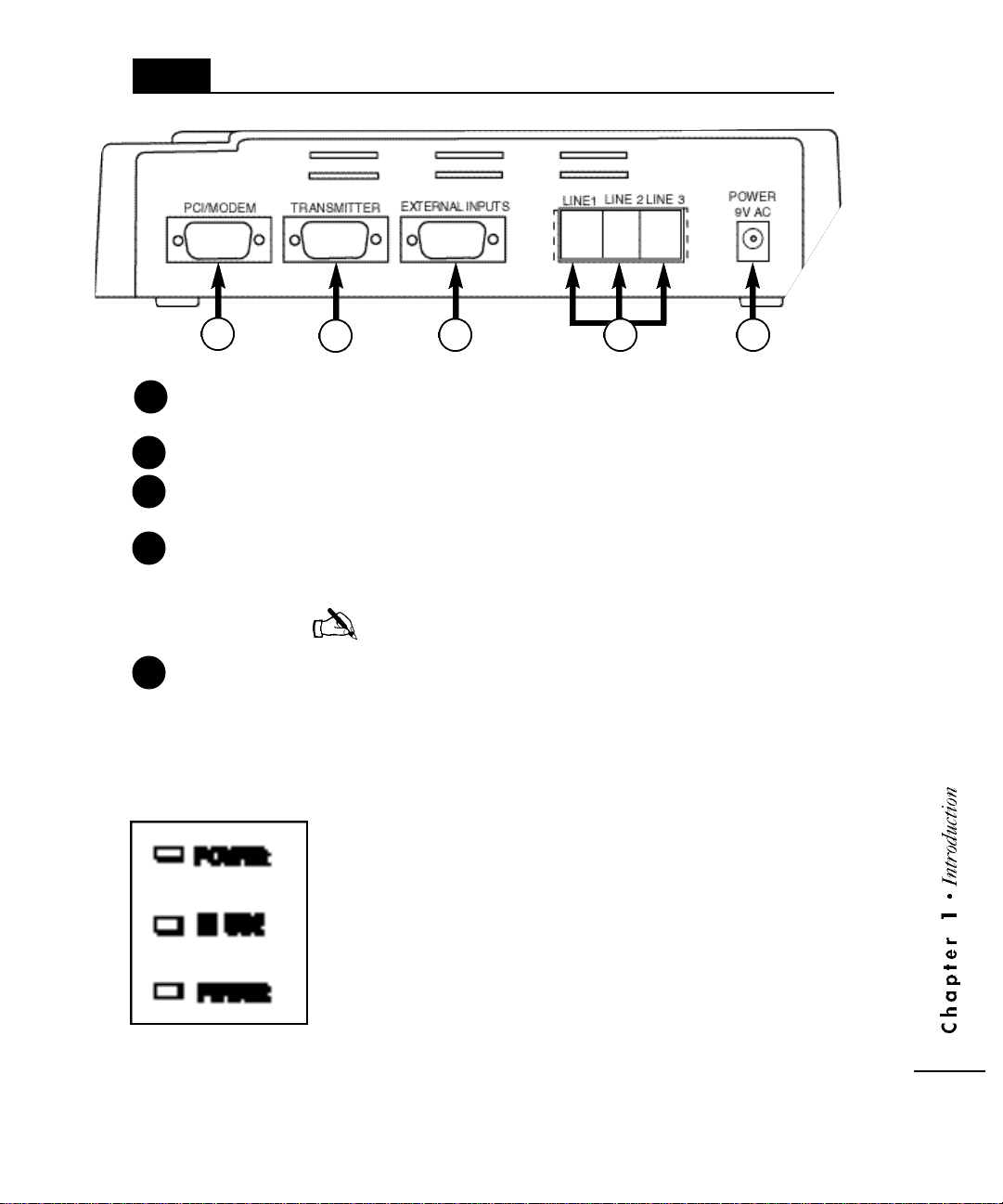
1.1.2
Physical Description
1
1
2
3
Line 1/Line 2/Line 3 t h ree Industry Standard Telephone (IST) analog communications
4
PCI/Modem connects the unit to a personal computer or modem
connector
Transmitter connects to the Transmitter Unit for local wireless paging.
External Inputs enables activation of contact closure s .
connector
2
for programming the APS Custom.
p o rts. Ports 1 and 2 service incoming calls. Port 3 handles all
o v e rhead pages and announcements, and wide area pages.
3 54
NOTE: The terms “Line” and “Port” are interc h a n g e a b l e .
5
9V AC jack accepts 9V AC power to the unit. The power supply
included with the unit provides 9V AC at 780mA
from a 110V AC source.
The front of the unit displays three LED indicators,
POWER, IN USE and PROGRAM.
POWER
IN USE
(red) lights when the unit is on.
(green) lights when there is activity on the APS
Custom. Activity is defined as any
inbound or outbound call transactions.
PROGRAM
(green) lights when the unit is in programming mode.
The unit is in programming mode when
connected to the personal computer interface
for database operations or when recording
names or announcements.
1 • 3
Page 10

1.1.3
Personal Computer Interface (PCI)
The PCI enables you to create and configure a database that controls the behavior of the
unit. Using a personal computer, you configure PBX-specific paging, announcement and
contact closure information, store detailed system information and provide remote access
to the unit. The personal computer is not necessary for daily unit operation. For more
detailed information on the PCI, refer to Chapter 3, Programming the APS Custom.
1.2
1.2.1
System Requir e m e n t s
To use the APS Custom and its associated software, the PBX must support IST
connections with Overhead Paging, Call Park, Call Transfer and Call Pickup features.
For more detailed information on these features, refer to Section 2.1, Understanding
System Requirements. In addition, the computer system must meet the minimum system
requirements outlined below for programming.
H a rd w a r e
The minimum hard w a re re q u i rements that your Personal Computer (PC) system needs to
run the PCI include:
• 486 DX4 processor or higher (Pentium highly recommended)
• 16 MB RAM
• Hard Drive with at least 100 MB of free space
• CD-ROM drive
• 3 1/2” disk drive
• Available serial port or installed modem
1 • 4
1.2.2
S o f t w a r e
The minimum operating system and software re q u i rements that your PC system needs to
run the PCI include:
• Windows® 95, Windows 98, or Windows NT 4.0
• Procomm Plus® 32 communications software, version 4.7 (See Appendix E)
Page 11

C h a p t e r T w o
2
I n s t a l l i n g t h e A P S C u s t o m
The APS Custom is designed for quick and easy
installation. This section provides the information
needed to install the APS Custom successfully.
NOTE: Pre-installation and user information surveys,
located at the end of this manual (Appendix F), are
also provided to aid in the installation of the unit.
2.1
Understanding System Requirements
B e f o re installing the unit, ensure that your telephone system supports a minimum of one
IST analog port. To customize your unit to best meet your needs and take full advantage
of the functions offered by the APS Custom, ensure your PBX supports the associated
features as identified. If your PBX does not support one or more of these features, specific
f u n c t i o n s of the APS Custom will not be available. Refer to Chapter 4, Programming the
PBX and Appendix C for more detailed information on PBX feature requirements.
T h ree Industry Standard re q u i red for maximum perf o rmance and capacity.
Telephone (IST) port s The following configurations are also supported, with the
noted suggested site conditions.
One IST analog port — if wide area and overhead paginga re
not re q u i red and low traffic volume is expected
Two IST analog ports — if wide area and overhead paging
a re not re q u i red and high traffic volume is expected
Two IST analog ports — if wide area and/or overhead
paging are re q u i red and low traffic volume is expected
T h ree IST analog port s — if wide area and/or overhead
paging are re q u i red and high traffic volume is expected
Call Forw a rd ability to forw a rd calls from one system extension to another
Call Park ability to place an outside call into a “global hold” re s o u rc e
on your PBX. Ty p i c a l l y, a “parked” call occupies one of a
set of park slots or “orbits” on your PBX. The call may be
retrieved from this “global hold” slot or “orbit” via a
specific command from any PBX extension. The park range
is limited to 3 digits.
2 • 1
Page 12

Pickup Park ability to retrieve a call placed into a “global hold”
(a.k.a. Answer Back) resource slot or “orbit”. This feature is present in PBX
systems offering Call Park capabilities.
Hunt Group ability to define a set of PBX extensions as accessible via a
single master extension number. Typically, consists of two or
more extensions configured so that a single PBX extension
number will, when called, cause a ring to appear on any
one of the set of extensions making up the Hunt Group.
In addition to the minimal set of PBX features described above, the following feature
enhances the functionality of the APS Custom.
Park Recall ability for the PBX system to supervise calls which have
been placed into Park Orbits (see Call Park above). Upon
expiration of a set timeout, the calls are automatically
removed from orbit and forw a rded to the specified extension.
Ty p i c a l l y, the calls are re t u rned to the PBX extension that
originally parked the call. However, some PBX’s allow
f o rw a rding the call to another extension.
2 • 2
2.2
!
I n c reasing Transmitter Coverage
Before installation, it is important to consider the paging area to be covered by the
transmitter. The range and performance of the transmitter can be improved with the
proper positioning of the antenna. The antenna is installed inside the building near the
t r a n s m i t t e r. For example, to cover a large paging area, or in an area where
transmission interf e rence is expected, you can boost overall perf o rmance by positioning
the antenna as high up on the building as feasible. When paging throughout a
multi-story building, better perf o rmance may result from positioning the antenna at the
midpoint of the building. To ensure optimal placement of the transmitter, refer to section
3.6.6, Performing a Pager Site Survey.
WARNING: Do not attempt to operate the paging system without the
antenna connected to the paging transmitter. Damage
to the paging transmitter may result.
WARNING: Do not use “cable TV” type coaxial cable, or any other
!
type of cable not specifically designed for 400MHz
wireless paging requirements. Damage to the paging
transmitter may result.
Page 13

2.3
Mounting the System Components
To ensure a proper installation of the APS Custom, follow the guidelines below.
For the APS Custom Control Unit:
• Never install the unit in a damp area or where the unit may be exposed to
moisture or extreme fluctuations in temperature.
• Never install the unit in areas where the ambient temperature goes below 40
degrees (F) or exceeds 90 degrees (F).
• Connect the unit to the transmitter using the shielded RS232 type data cable
provided with your transmitter. Route the connections to keep them clear of
induced magnetic or electrical noise. The distance between the unit and
transmitter should not exceed 50 feet, or 15 meters. The data cable should
be connected securely to the APS Custom transmitter port on one end and to
the proper transmitter data port on the other. Please refer to Appendix D,
Wave Ware Paging Transmitter.
• Mount the unit and transmitter near a standard 110V AC power source.
The unit comes equipped with a 9V AC power jack. The power supply
included with the unit provides 9V AC at 780mA from a 110V AC source.
• Install the APS Custom as a wall-mount unit. Drill templates are provided
for the unit to assist the installer in properly placing the mounting screws.
• When mounting the unit on hollow walls or other similar materials, use
suitable fasteners. Plastic screw anchors are provided.
For the transmitter:
• Never install the antenna near or adjacent to telephone, public address or
data communications lines, or overhead power cables.
• Avoid running antenna cables adjacent to other cables.
• Avoid mounting the transmitter near telephone exchanges or computer
equipment.
• Always use 50-ohm coaxial cable between the antenna and transmitter.
WARNING: Coaxial cable used for television, satellite or CCTV
!
installations is normally 75-ohm and unsuitable for
connecting the antenna and transmitter.
• Avoid mounting the unit on or near foil-backed plasterboard, metal mesh or
wire-reinforced glass, metal sheeting, large mirrors suspended ceilings or
elevator shafts.
2 • 3
Page 14

• Avoid direct contact with the circ u i t ry to prevent electrostatic discharge (ESD).
• NEVER transmit without an antenna attached to the transmitter.
• Ensure proper data pin connections.
• During normal paging operations, position the paging transmitter antenna
vertically to maximize paging range. When using a transmitter in the shelf
mount configuration, use a right angle coaxial antenna adapter for proper
antenna positioning.
• Install the APSXMTR unit as a wall-mount unit or in some other secure
location.
• Right angle brackets and screws are provided for wall mounting.
2.4
Connecting the Unit
The physical components of the system include:
APS Custom unit
✔
✔ Transmitter
✔ Antenna
✔ DB9 Null Modem Cable
✔ DB9 Cable to Flying Leads
✔ DB9 to DB25 Modem Cable
To connect the unit, follow the steps below.
1. Connect the telephone line inputs. Line 1 is for Port 1 and must be connected
correctly to ensure successful system operation. Line 2 is for Port 2 used as
the second call handling port in higher traffic. Line 3 is for the outbound
port, Port 3, used for wide area and/or overhead paging.
NOTE: To ensure proper operation of the unit, the physical line connections
must match the information specified in the PCI database.
2 • 4
2. Connect the data cables to the unit and transmitter. The power LED on the
unit will be lit.
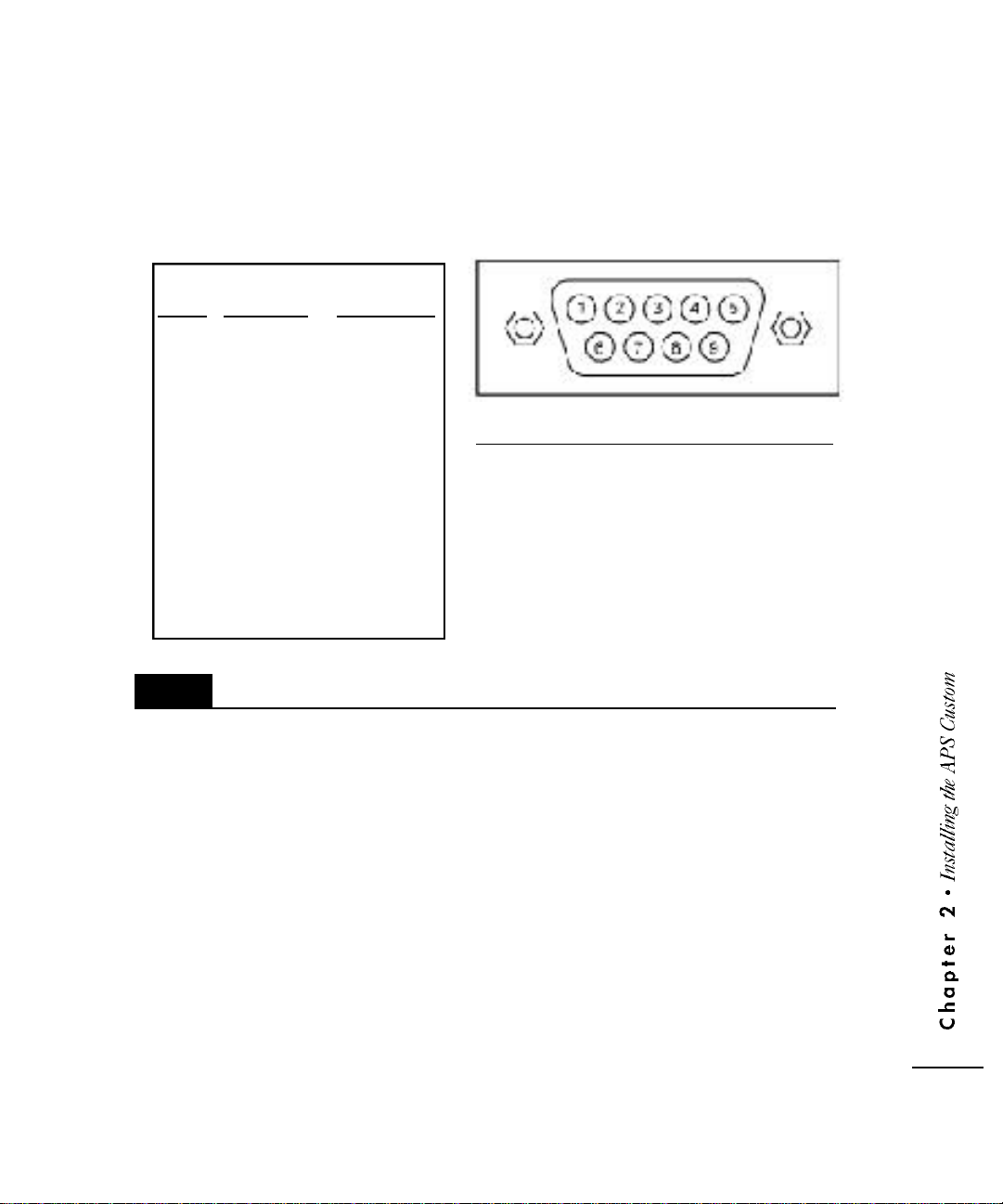
3. Optionally, connect one or more of the contact closure port pins to external
dry contact closure type switches. Please refer to the contact closure port pin
specification for proper connection (Figure 2-1). A closure between any contact
pin (1-8) and Common (pin 9) will cause that event to activate. For more
detailed information on contact closures, refer to section 3.2.5, Configuring
Contact Closure Event Scripts.
Page 15
4. Connect the PCI interface. To send the pre-programmed database,
refer to section 3.6.3, Sending the Database.
5. If you are connecting a modem, go to section 2.5, Connecting the Modem n o w.
If not, go on to Step 6.
6. Connect the output plug from the power supply to the 9V AC jack on the
unit. Plug the power supply into a 110V AC outlet. The power LED on the
unit should be lit.
Cable
Pin Function Color Code
1 Contact 1 Brown
2 Contact 2 Red
3 Contact 3 Orange
4 Contact 4 Yellow
5 Contact 5 Green
6 Contact 6 Blue
7 Contact 7 Purple
8 Contact 8 Grey
9 Common White
2.5
Connecting the Modem
Verify dipswitch settings on the modem. 1-4-6-7 UP. 2-3-5-8- DOWN.
To set up the modem, do the following:
1. Make sure that both the APS Custom and the modem are turned off.
2. Connect the modem to the PCI/Modem port on the APS Custom unit. Use
the modem cable supplied with the APS Custom.
3. Connect the modem to a phone line with a telephone cord. Note the
number for that phone line.
4. Connect the modem's power supply to the modem and plug it in.
5. Turn on the modem.
6. Connect the output plug from the power supply to the 9V AC jack on the
unit. Plug the power supply into a 110V AC outlet. The power LED on the unit
should be lit. The INUSE Program LEDs will flash several times and then stop.
F i g u re 2-1: Contact Closure to Pin Assignments
The APS Custom will automatically detect the modem and initialize it. The APS Custom is
now ready for remote access.
2 • 5
Page 16

2.6
Verifying Installation
To avoid operational problems and verify that the unit was installed corre c t l y, perf o rm the
following checks.
• Check the unit to transmitter data cable connections. Incorrect cable
connections, together with an incorrect signaling format, are the most
common installation errors.
• Verify that the transmitter and pager frequencies match.
• Ensure that the pagers are at least 10 feet (3 meters) from the transmitter
and antenna.
• Ensure that the pager batteries are installed and the pagers are turned on.
• Ensure the POWER LED lights on both the unit and transmitter are lit. If the
LED lights are not lit, verify the power connections.
• Ensure that the TX LED on the transmitter lights for the duration of
transmission. If not, check the data cables.
• Verify that the unit can pick up a ringing line.
• Verify that the PCI can communicate with the unit
(see section 3.0, Programming the APS Custom).
• Verify that the database was sent correctly.
• Verify that user’s pager CAP codes (Local Pager IDs) were correctly
programmed into the database.
2 • 6
• Verify interface with the PBX - overhead paging, transferring a call, etc.
Page 17

C h a p t e r T h r e e
3
P r o g r amming the APS Custo m
The APS Custom PCI enables you to:
• Create, modify and store user databases
• Store system information, including PBX parameters, port
data and paging data
• Receive and send user and system information to the APS Custom
• Send APS Custom system firmware
• Provide access to the APS Custom unit via direct or modem
connection
• C reate and edit event scripts comprised of overhead announcements,
user names, wide area pages and local wireless pages
• Associate scripts with contact closures
• Assist the installer in testing the local paging system using
the Pager Site Survey
3.1
Before installing the APS Custom Personal Computer Interface (PCI), check the minimum
system requirements discussed in Section 1.2, System Requirements. If the PC does not
meet the minimum requirements, you may have trouble installing or using the software.
The PCI installation re q u i res the 3 1/2” diskette that accompanies the APS Custom PCI
s o f t w a re package (PEC 5338-SOF Com Code: 408129064) and a copy of Procomm
Plus® 32 communications software, version 4.7.
NOTE: Install the Procomm Plus software before installing the APS Custom
3.1.1
To install the PCI software on a PC running Windows 95/98 or NT 4.0, follow the steps below.
Installing the Personal Computer Interface
PCI as the APS Custom installation procedure checks for the existence
of the Procomm Plus 32 communications package (see Appendix E).
P C I Setup on Windows® 95/98/NT System
1. Close any open applications.
2. Insert the installation diskette labeled “Install Disk 1” into the disk drive
(usually drive A:).
3. Click on the “Start” button and select Run to display the “Run” Dialog box.
4. Click on the “Browse” button to display the Browse dialog box. Find and
click on the 3 1/2” Disk Drive (A:) icon. Click on Open.
3 • 1
Page 18

5. Select Setup and Click Open to place the “Setup.exe” file in the File name
text box. Click on the Open button to return to the Run dialog box.
6. Click on the “OK” button to begin the Setup Process.
NOTE: It may take a few minutes for the introductory graphic to
appear on the screen.
7. Follow the instructions on the screen.
8. The PCI selects a default directory in which to install the program. If the PCI
does not detect the Procomm Plus Aspect Directory, the program prompts
you to specify a directory. Selecting the default is recommended.
9. Select OK to complete the installation. If you are using Windows 95/98,
shortcut icons are created on the desktop for quick access to the PCI
software. Shortcut icons will not be created in Windows NT.
10. Remove the installation diskette from the drive.
3.2
The PCI enables you to create one or more databases to interface with the APS C u s t o m
unit. The information entered is specific to the unique application of the configure dunit (e.g.,
PBX information, site-specific information, etc.). Information, including user re c o rds, user
g roups and system configuration data can not be shared among databases, and must be
e n t e red for each database created. Use the mouse or Tab key to move between data fields.
C reating the Database
NOTE: Additions and/or changes to the database are stored immediately in the
database (there are no separate steps required to save additions and/or
changes to the database).
3.2.1
The ProComm Plus and APS Custom applications should be loaded (see Appendix E,
ProComm Plus® 32 Software Installation). To begin entering the necessary system data,
select the APS Custom PCI icon. (No icons are created in Windows NT. Windows NT
users can launch APS Custom PCI from the Start Menu. Click on Programs and select
APS Custom PCI.) The PCI Main Dialog Box appears on the screen (see Figure 3-1).
Defining Database Characteristics
3 • 2
Page 19
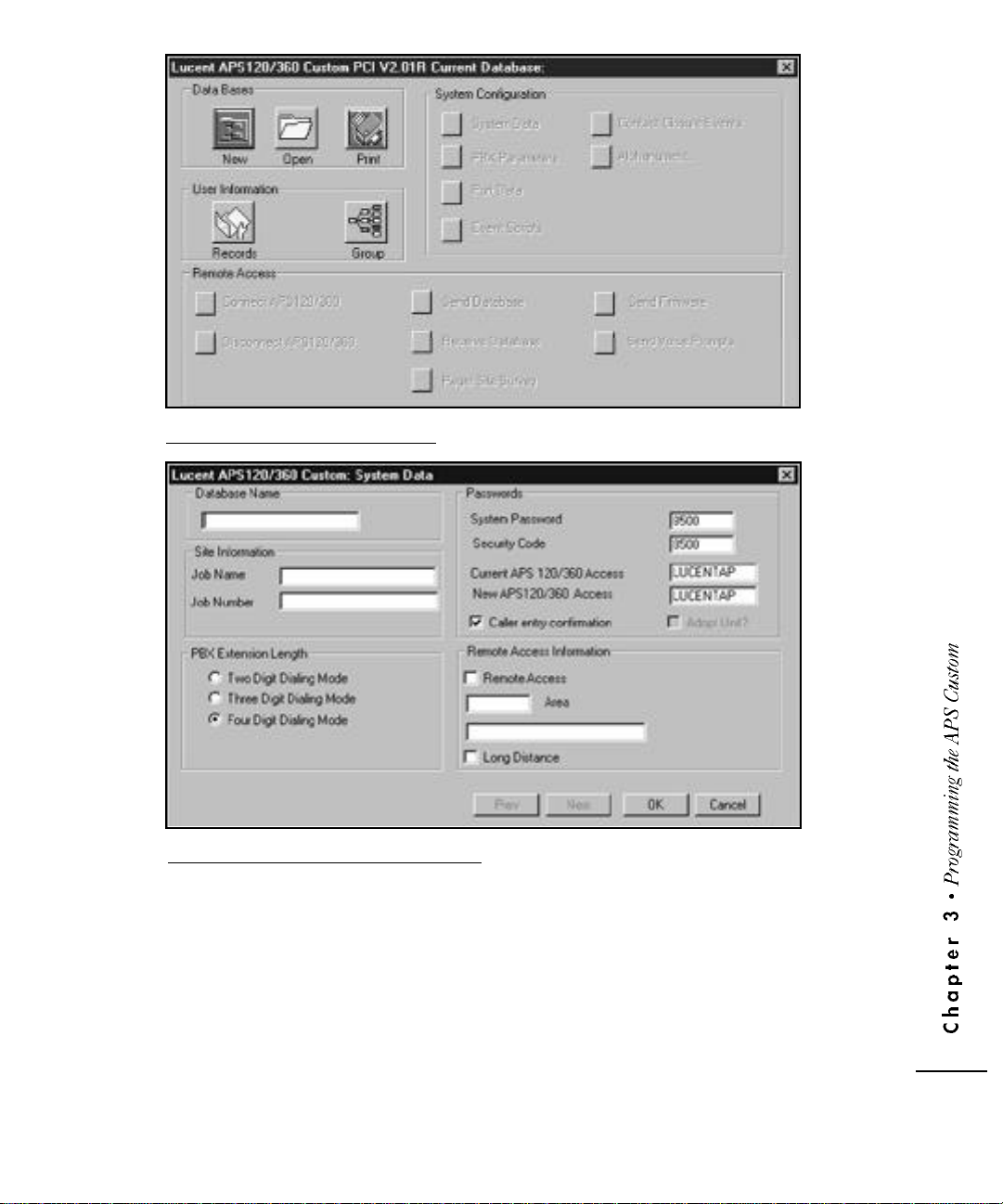
F i g u re 3-1: PCI Main Dialog Scre e n
F i g u re 3-2: Database Information Scre e n
To create a database, select the New Database icon at the top of the screen. The Database Information screen appears (Figure 3-2).
Database information fields include:
Database Name a user-defined 20 character alphanumeric field.
Site Inform a t i o n optional fre e - f o rm fields.
(Job Name, Job Number)
PBX Extension Length selectable field identifying the dialing mode of the PBX.
You select from a two, three or four-digit dialing mode.
3 • 3
Page 20

WARNING: PBX Extension Length can ONLY be specified during the initial
!
database setup. If entered incorre c t l y, or if future modifications
a re needed, the database must be deleted and re c re a t e d .
Passwords System Passwor d and Security Code - are four-digit
(Modify Announcements, numbers used to secure the unit and database inform a t i o n ,
Modify Programming) and control access to the unit. These passwords are
needed to record or delete overhead announcements or
names. The system defaults to 6263 for the System
Password and 9832 for the Security Code. Changing these
passwords is recommended. (See Appendix B, System
Passwords for more information.)
Current APS 120/360 Access - user-defined alphanumeric
password to connect the APS Custom PCI program to the
APS Custom unit. The APS Custom 120/360 unit is
shipped from the factory with the APS 120/360 Access
password set to LUCENTAP. If you are connecting to the
APS Custom unit for the first time and the APS Custom unit
is new, the Current APS 120/360 Access field should be set
to LUCENTAP. When creating a new database with the
APS Custom PCI program, the New APS 120/360 Access
field defaults to LUCENTAP. If the APS 120/360 Access
password in the APS Custom unit has already been
changed, the updated password is entered in the Current
APS 120/360 Access field.
3 • 4
New APS 120/360 Access - user-defined alphanumeric
password to change the APS 120/360 Access password
within the APS Custom unit. Normally, the password in the
New APS 120/360 Access field will be identical to the
password in the Current APS 120/360 Access field. When
you need to change the APS 120/360 Access password for
the APS 120/360 unit, the new password must be entered
in the New APS 120/360 Access field. Changing the APS
120/360 Access password in the APS Custom unit is
recommended.
Caller Entry Confirmation - selectable field that controls the
prompting/confirming requested of a caller. The system
defaults to requiring confirmation (e.g., "You entered extension
1234. If this is correct, press one. If you would like to
specify a new extension, press 2.")
Adopt Unit - field for Lucent Technologies factory use only.
When you complete the database information, select OK. A confirmation message
appears on the screen. Select OK. The database name appears at the top right of the
screen. You can now complete the System Configuration, User Information and Remote
Access sections of the database.
Page 21
3.2.2
The System Data option enables you to review and/or modify current database
characteristics. You can modify both site and password information, including Caller
Entry Confirmation. Database Name and PBX Extension Length are static fields and can
not be modified.
Modifying System Data
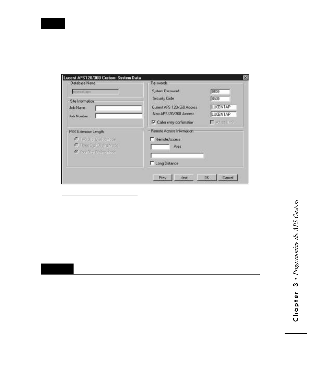
F i g u re 3-3: System Data Scre e n
To modify system data, access the APS Custom System Data Screen (Figure 3-3) by
selecting the System Data option from the PCI Main Dialog Screen (Figure 3-1). Select
the field to modify, delete the existing data values, and type the new system inform a t i o n .
Repeat as necessary to update additional system data.
Select OK to accept the updated system data, or Next to move to the PBX Parameters scre e n .
3.2.2.1
To change the Access password in the APS Custom unit do the following:
1. Run the APS Custom PCI program. Then, open the database for the target
2. F rom the PCI Main Dialog window, click the System Data button. In the System
Changing the Access Password
APS Custom unit.
Data screen (Figure 3-3), there are two APS 120/360 Access Password fields.
The Current APS 120/360 Access field will show the current Access password .
The APS Custom unit is shipped from the factory with its Access password set
to LUCENTAP.
3 • 5
Page 22

3. Enter the APS 120/360 Access password you want to use in the New APS
120/360 Access field. The Access password must be 8 characters in length
and it is case sensitive. Click the OK button and the APS Custom PCI program
will return to the PCI Main Dialog window.
4. Connect to the APS Custom unit. Once connected, click the Send Database
button to send the database. The Access Password in the APS Custom unit will
not be changed unless the database is sent. Once the database has been sent
successfully, the APS Custom unit's Access Password will be set to the new
password. The APS Custom PCI program will then update the Current APS
120/360 Access Password field to match the New APS 120/360 Access
Password field.
5. Click the Disconnect button and the Access password change process is
complete. The Current APS 120/360 Access password now matches the New
APS 120/360 Access password in the System Data screen.
3.2.3
The PBX Parameters option enables you to specify how the APS Custom interfaces with
the PBX to perform call transfers, parking, and interface with the voice mail system. PBX
timing parameters are also specified on this screen.
Access the PBX Parameters screen (Figure 3-4) by selecting the PBX Parameters option
f rom the PCI Main Dialog screen (Figure 3-1). When the parameters are entered, select
OK to close the screen, or Next to move to the Port Data scre e n .
WARNING: The PBX Parameters screen displays the PBX Extension
!
Setting PBX Parameters
Length specified during database creation. PBX Extension
Length can be specified ONLY during the initial database
setup. If entered incorre c t l y, or if future modifications are
needed, the database must be deleted and re c re a t e d .
3 • 6
Page 23
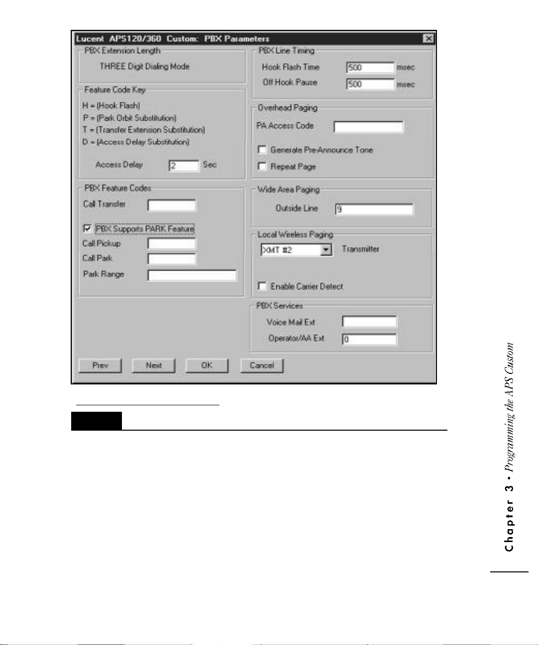
F i g u re 3-4: PBX Parameters Scre e n
3.2.3.1
PBX Feature Codes include Access Delay, Call Tr a n s f e r, Call Pickup, Call Park Dialing
Sequences and Park Range.
(a.k.a. Answer Back) pick up a parked call.
Specifying PBX Feature Codes and Ser v i c e s
Access Delay specifies the number of seconds associated with the Access Delay
Substitution Feature Code key.
Call Transfer identifies the dialing sequence required for an analog station to
transfer a call.
H re p resents the (H)ook Flash signal sent to the PBX. A Hook Flash is a
m o m e n t a ry ‘on hook’ signal to the PBX. The Hook Flash and Off
Hook Pause duration values are specified in the PBX Line Timing
section.
T re p resents the (T)ransfer code used to identify where the
extension information is placed in the transfer string.
Call Pick up identifies the dialing sequence required for an analog station to
3 • 7
Page 24

Call Park identifies the dialing sequence re q u i red to park a call. Call Park is a specialized
type of global hold that enables any individual familiar with the park orbit to
pick up the parked call.
Park Range identifies the orbit or orbits in which calls are parked. Orbits do not
need to be sequential and you can specify up to 20 park orbits. Orbits
can be listed individually or as ranges of numbers, e.g., 1, 2, 4-7, 9.
3.2.3.2
The PBX Line Timing parameter (see Figure 3-4) specifies the Hook Flash Time and Off
Hook Pause Timing. The Hook Flash Time field can be any numeric value from 100 to
2500 milliseconds. The Off Hook Pause Timing field can be any numeric value from
300 to 6000 milliseconds. The default for both fields is 500 milliseconds.
3.2.3.3
S t a n d a rd announcements and prompts are pre - re c o rded on the APS Custom. The APS C u stom enables users to have one person re c o rd basic overhead paging messages, includingu s e r
names, numbers and specific system messages. Overhead pages have two basic form a t s .
R e c o rding of user names utilized for called party confirmation and overhead paging is
recommended and is re q u i red for overhead paging. Numbers 0 through 9 and system
messages “please pick up the call parked on” and “please dial extension” can be re c o rded as special announcements.
To re c o rd special announcements, press the
menu followed by one of the keys identified below.
Specifying PBX Line T i m i n g
Configuring Overhead Paging
1) [name] please pick up the call parked on [number]
2) [name] please dial extension [number]
where [name] represents the called party, and [number] represents either the
parked extension or return call number.
(star) key from the announcement selection
*
3 • 8
* “Please dial extension number”
*
)
#
# “Please pick up the call parked on”
)
0 “zero”
0
)
1 “one”
1
)
2 “two”
2
)
3 “three”
3
)
4
)
5
)
6
)
7
)
8
)
9
)
“four”
“five”
“six”
“seven”
“eight”
“nine”
Page 25

Follow this pro c e d u re until all special announcements are re c o rded. If these special
announcements have not been re c o rded, the APS Custom uses the pre - re c o rded prompts listed above. For more information, see Section 5.2.2, Administering Announcements.
There are four components for configuring the Overhead Paging functions of the PBX (see
Figure 3-4).
• PA Access Code
• Access Delay
• Generate Pre-Announce Tone
• Repeat Page
The PA Access Code field identifies a code of up to seven digits for engaging Overhead
Paging. A ‘D’ within the string represents a delay as specified in the Access Delay field.
Access Delay defines the number of seconds re p resented by the ‘D’ within the PA Access Code.
The PCI automatically inserts the ‘D’ at the end of the Overhead Paging Access String. To insert
additional delays (i.e., if DTMF is re q u i red to select a specific zone), insert a ‘D’ in the appropriate spot in the PA Access Code. The access delay can be 1 to 9 seconds.
Generate Pre-Announce Tone is available as a selectable field that instructs the APS Custom to
i n s e rt a tone between overhead pages. The tone is played when two or more overh e a d
announcements are queued in the same time period. The system defaults to Pre-Announce To n e
o ff. To activate the Pre-Announce Tone, check the box.
Repeat Page is a selectable field that instructs the APS Custom to repeat the overhead
page automatically when selected. The system defaults to Repeat Page off. To activate
Repeat Page, check the box.
3.2.3.4
The Outside Line field within the Wide Area Paging box (see Figure 3-4) enables you to
specify the number(s), often a ‘9’, necessary to dial outside of the PBX. A string of up to
four digits can be entered in this field.
3.2.3.5
To use local wireless paging with the APS Custom, you need to specify the type of transmitter being used. Select “XMT #2” in the transmitter box of the Local Wireless Paging
section (see Figure 3-4, PBX Parameters Screen).
There is also an option to Enable Carrier Detect. The Carrier Detect option enables the
Wave Ware Transmitter to search for other activity on the frequency. If there is none, the
page will be sent. If so, it will wait for clearance and then send the page. The default for
this option is disabled (i.e., no carrier detect).
Configuring Wide Area Paging
Configuring Local Wi reless Paging
NOTE: When the Carrier Detect option is off, pages may be affected by frequency
interference or not detected.
NOTE: The Carrier Detect option assists with paging when two APS Custom
units, or other transmitter devices, are located in close enough proximity
to cause frequency interference.
3 • 9
Page 26

3.2.4
For the APS Custom to operate correctly, you must specify the extensions of the two PBX
service ports connected to the unit. If the extension for Service Port 1 is missing or
entered inaccurately, the recording feature will not operate correctly.
Assigning Port Extensions
To specify the extension numbers, select the
Port Data button from the PCI Main Dialog
Box (Figure 3-1). Enter the extensions for
Service Ports 1 and 2 on the Port Information
s c reen (Figure 3-5). For more detailed
information on service ports, refer to section
2.4, Connecting the Unit.
Select OK to re t u rn to the PCI Main Dialog Box,
or Next to proceed to the Event Scripts scre e n .
F i g u re 3-5: P o rt Information Scre e n
3.2.5
The Event Script Editor (Figure 3-6) enables you to create and edit event scripts comprised
of overhead announcements, user names and local pages. You can configure up to 30
scripts. Each script may be assigned to any of the e i g h t contact closure s .
To create or modify a script, select the Event Scripts button from the PCI Main Dialog Box
( F i g u re 3-1). Select a script number by clicking on the arrow key of the Script Number
field.
Move the cursor to the
Script Name field, type
a script name of up to
20 characters, and proceed with the script
i n s t ructions specified in
section 3.2.5.1, A d d i n g
an Overhead Page to a
Contact Closure Event
S c r i p t section below.
Configuring Contact Closure Event Scripts
3 • 10
F i g u re 3-6: Event Script Editor Scre e n
Page 27

3.2.5.1
You can create three types of Overhead paging scripts:
These can also be combined.
To add an overhead page to a script:
1 ) Select the Overhead Page button on the Event
2 ) Select the type of page from the
3 ) Complete the Event Script using the menu selection associated with each type of paging
Adding an Overhead Page to a Contact Closure Script
• An announcement (a)
• A user name (n)
• A digit string (d).
Script Editor screen (Figure 3-6).
F i g u re 3-7: O v e rhead Paging Script Elements Scre e n
O v e rhead Paging Script Elements screen (Figure 3-7).
announcement. Select a button for an announcement, user name or digit string.
Announcement
4 ) When prompted, specify the announcement number (2 through 8).
5 ) Select OK. The system re t u rns to the Overhead Paging Script Elements scre e n .
6 ) To add additional announcement numbers to the script, follow steps 3 through 5 above.
7 ) Select OK. The system automatically populates the Event Script Field identifying the
type of page selected with the associated page type character (a) and announcement
n u m b e r. For example, for “Oa3”, “O” re p resents overhead, “a” re p re s e n t s
announcement and “3” re p resents the announcement number.
NOTE: See Section 5.2.2.1, Recording an Announcement and Form 2 in
Appendix F.
User Name
4 ) When prompted, select Yes or No to specify whether to sort the available
user names or not.
5 ) Using the mouse or up and down arrow keys, highlight the re q u i red user name
and select OK.
6 ) Repeat steps 3 through 5 until all re q u i red user names have been selected.
7 ) Select OK. The system automatically updates the Event Script Field, identifying the
type of page selected with the associated character (n) and user number. For
example, for “On1”, “O” re p resents overhead, “n” re p resents name and
“1” re p resents the user associated with User Record number 1.
NOTE: See Section 5.2.1.1, Recording a User Name.
NOTE: If a user name has not been recorded, no overhead pages can be sent
for that extension.
3 • 11
Page 28

Digit String
4 ) When prompted, type the desired digit string.
5 ) Select OK. The system automatically updates the Event Script Field identifying the
type of page selected with the associated character (d) and digit string selected.
For example, for “Od1234”, “O” re p resents overhead, “d” re p resents digit string
and “1234” identifies the digit string entere d .
3.2.5.2
To add a wireless page to a script, follow the steps below.
1 ) Select the Wi reless Page button on the Event Script Editor screen (Figure 3-6).
2 ) Select Yes or No to specify whether or not the system should sort user names
3 ) Using the mouse or up and down arrow keys, highlight the required name
4 ) If using alphanumeric pagers, you will be prompted to select the type of page
Adding a Wi reless Page to a Contact Closure Script
alphabetically by last name.
and select OK. This identifies which user the unit will page.
(numeric or alphanumeric) (see Figure 3-8).
• For numeric pages, enter the numeric
string and select OK.
• For alphanumeric messages, enter the
desired text string and select OK.
F i g u re 3--8: O v e rhead Paging Selection Scre e n
NOTE: Numeric pages can have a maximum
of 20 numbers. Alphanumeric pages can have a maximum of 30 characters.
5 ) Repeat steps 1 through 4 until all re q u i red user names have been selected. The
system automatically updates the Event Script Field as necessary.
6 ) Select OK.
3 • 12
3.2.5.3
The Event Script Editor also enables you to copy the Event Script Field to another script.
This is especially useful when diff e rent messages or pages need to be sent to the same
g roup of individuals or assigned to multiple contact closures. Multiple pre-defined
messages can be created for the same group of users, changing only the text portion of
the script. For example, you can send a message of “000” to inform paged parties that
help is needed with the telephones and a message of “111” to request everyone to meet
in the customer service area. Using the Copy command and changing the “000” to
“111”, you can send the same group of individuals both messages, eliminating tedious
re - e n t ry of all individuals to be paged.
To copy a script, follow the steps below.
1 ) Select the Copy button from the Event Script Editor screen (Figure 3-6).
2 ) The system prompts you for the script number to which to copy the existing script.
Copying an Existing Contact Closure Script
Enter the number and select OK. A confirmation message is displayed.
Page 29

3.2.6
F i g u re 3-9: Contact Closures Scre e n
The “External Inputs” 9-pin serial port on the APS Custom controls contact closures. Pins
1 through 8 are the inputs for the contact closures. When one of these inputs is shorted to
common (Pin 9) by an external device, the contact is considered “closed”, triggering the
script associated with that contact to be executed. The scripts are defined and associated
with a particular contact in the APS Custom PCI.
Configuring Contact Closure s
Each of the eight contacts can be connected to a separate device such as a door latch,
doorbell or motion sensor. Altern a t e l y, all of the contact closures can be wired to a box
used by a receptionist to make announcements with the simple press of a button.
The Contact Closures Option enables you to assign a script number to a contact closure
for up to eight contact closures. Only valid (pre-defined) script numbers are displayed.
To configure contact closures (see Figure 2-1), follow the steps below.
1) Select the Contact Closures button from the PCI Main Dialog Box (Figure 3-1).
2) Enable the closure by selecting the Enable box for that Contact.
3) Select a valid script number using the down arrow key for the script number
field. The script name appears in the Name field.
4) Select OK to return to the PCI Main Dialog Box, or Next to proceed to the
Alphanumeric Messages screen.
NOTE: If the contact closure is not enabled, the script will not be
executed when the contact closure occurs.
NOTE: To disable a contact closure, remove the checkmark (✓) from the
Enable box associated with that contact.
NOTE: To configure contact closures 5 through 8, select “next” from the contact
closure 1-4 screen.
3 • 13
Page 30
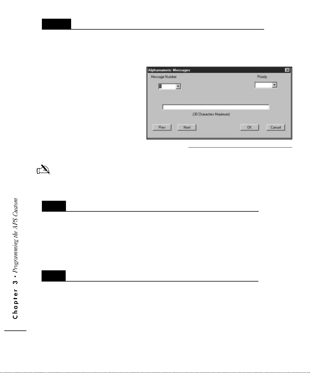
3.2.7
The Alphanumeric Messages option enables you to store up to 30 pre-defined messages
for local wireless paging. Each message can be up to 30 characters long and assigned
a priority — High or Normal — to indicate the importance or urgency of the message.
The APS Custom can transmit these alphanumeric messages to individuals or groups of
local wireless pagers.
To create an alphanumeric
message, follow the steps below.
1 ) Select the Alphanumeric button fro m
2 ) Select a message number using the
3 ) Move to the Priority field and select a High or Norm a l
C reating Alphanumeric Messages
the PCI Main Dialog Box (Figure
3-1) to get to the Alphanumeric
Messages screen (Figure 3-10).
down arrow key or by typing the
number directly onto the message
number field.
priority by clicking the down arrow key and highlighting the appropriate priority level.
F i g u re 3-10: Alphanumeric Messages Scre e n
NOTE: The system default is normal priority.
4 ) Move to the message field and type the message.
5 ) Select OK to re t u rn to the PCI Main Dialog Box or Next to move to the System Data scre e n .
3 • 14
3.3
3.3.1
Modifying an Existing Database
To keep announcement, user and pager information current, regular updates of database information are required. Database modifications can be done on an as-needed
basis or at scheduled intervals.
All database fields, excluding the PBX Extension Length, can be modified. PBX Extension Length must be set correctly during initial setup. If set incorrectly, or if future modifications are necessary, the database must be recreated with the correct extension
length.
Selecting a Database
In some cases, more than one database may exist. To select which database to modify, access the PCI Main Dialog Box (Figure 3-1). The name of the open database is
located across the top of the APS Custom PCI window. To open a database other than
the one identified at the top of the screen, follow the steps below.
1) Select the Open Database icon. A list of the available existing databases
appears on the screen.
2) Using the up and down arrow keys, highlight the database that you wish to
modify and select OK. The system prompts you to confirm that you are
finished configuring the current database and wish to open a new database.
3) Select OK to confirm you are finished and to open the newly selected database.
Page 31

3.4
C reating User Recor d s
3.4.1
F i g u re 3-11: User Records Scre e n
Entering User Data
The User Information feature enables you to add new users, and find, modify or delete
existing user re c o rds. To add, edit or delete user re c o rds, select the Records icon from the
PCI Main Dialog Box screen (Figure 3-1) to get to the User Records screen (Figure 3-11).
To create a new user re c o rd, follow the steps below.
1) Select the New button.
2) Type the last name, first name and extension of the new user.
3) Follow the steps identified for each specific field.
3.4.1.1
User passwords are unique, four-digit codes that control individual access to usermodifiable parameters, including the default paging method. Assigned, maintained and
modified by the administrator, user passwords can only be set, modified or deleted fro m
the User Records screen (Figure 3-11). Users do not have the ability to modify their
p a s s w o rd s.
Setting/Modifying User Passwor d s
3 • 15
Page 32

3.4.1.2
Users can have any combination of the three available paging methods. For each user,
specify whether or not that user can be reached via Overhead, Local Wi reless and/or
Wide Area paging. To specify which method(s) are applicable, select the re q u i red fields
on the User Records screen (Figure 3-11). A checkmark (
active for the associated user.
Defining the Available Paging Methods
✓) indicates that the option is
3.4.1.3
The Default Paging Method identifies the default paging option used to contact the
individual user. The default is modifiable by the administrator from the User Records
screen (Figure 3-11), or via telephone prompts by the user. A dot (
current default.
NOTE: It is important to ensure that the associated paging information
3.4.1.4
If activated, the Play Overhead Announcements option (see Figure 3-11) enables users
to trigger one of the recorded announcements. The system defaults to disallow playing
of overhead announcements. To activate the option, the field must be checked.
3.4.1.5
Selecting the Default Paging Method
.
) indicates the
is configured for the default paging option selected. For example, if
Wide Area Paging is selected as the default, ensure that the Wide
Area information is completed.
Activating the Play Overhead Announcements Option
Selecting the User May Disable Paging Option
3 • 16
The User May Disable Paging Option enables users to disable all paging options. To
allow users to disable all paging, the User May Disable Paging option box (see Figure
3-11) must be checked. The system defaults to prevent users from disabling paging.
3.4.1.6
You must enter the appropriate pager characteristics for each user.
Specifying Pager Attributes
For local wireless paging, enter pager type and Pager ID (CAP code or Local ID).
For wide area paging, enter pager service contact information.
Page 33

Local Wireless Paging Information
To configure the local wireless paging information (see Figure 3-11), follow the steps
below.
1) Select the specific type of pager used, numeric or alphanumeric.
The system defaults to numeric paging.
2) Enter the seven-digit CAP code in the “Local Pager ID” field, usually stamped
on the back or side of the pager. The CAP code enables the system to signal
the appropriate pager.
Wide Area Paging Information
To configure the wide area paging information (see Figure 3-11), you must have a
detailed knowledge of the specific paging service, including contact numbers, service
messages, prompts, etc. Using the information entered, the PCI builds a script that
enables the unit to access the paging services automatically. The script identifies the PIN
code (if required) and other information necessary to automate paging. Experienced
users can enter script information directly using the appropriate script abbreviations.
W precedes the digit representing the wait time (in seconds) before proceeding to the
next step in the paging process. Actual wait time depends on the specific paging
service and its associated user prompts and timing. Wait time can be from one
to nine seconds .
NOTE: Longer wait times can be obtained by using multiple instances. For
example, to obtain a 15 second wait time, simply enter W9W6
(or, 9 + 6 seconds = 15 seconds).
M indicates where in the script the caller’s telephone number is to be inserted.
All other digits, including
the string.
For example, to enter the wide area paging information for User A:
1) Enter the Wide Area Phone Number for the associated paging service. This
should include specific dialing information (e.g., a “1” before the area
code, etc.).
2) On the Wide Area Information field, type W7 to instruct the system to wait
seven seconds after dialing the paging service access number before
entering the PIN.
3) Type the PIN for the specific user, e.g., 1234567#.
(star) and # (pound), are sent in the sequence specified by
*
3 • 17
Page 34

NOTE: Many paging services require all
entries to be followed by the #
(pound) key.
4) Type W2 to instruct the system to wait
two seconds.
5) Type M to identify where to insert the
specific message.
6) Type # (pound) to indicate the end of
the message. This is only applicable for
those services that require entries to be
followed by the # (pound) key.
Figure 3-12 illustrates the resulting Wide Area
Information.
F i g u re 3-12: Wide Area Information Scre e n
3.4.2
3.4.3
Modifying User Data
To find or modify an existing user, follow the steps below.
1) Select the Find button on the User Records screen (Figure 3-11). The system
enables you to search by extension number, first or last name. For example,
to locate John Smith, type the extension number, John or Smith, or simply
enter the first letter or first few letters of the user’s name.
2) If the system finds more than one user that matches the specific search
criteria, it suggests a match and requests confirmation.
3) Select Yes to accept the match or No to view alternate matches.
4) If you select No, the next possible match (if any) is displayed on the screen.
5) Repeat steps 3 through 5 until the correct user is identified or no matches exist.
Deleting User Data
To delete an existing user (see Figure 3-11), follow the steps below.
1) Find the user record you wish to delete by following the steps in section
3.4.2, Modifying User Data.
2) Select the Delete button. The system prompts you to confirm the deletion.
When you select the Delete button, the current user record is removed from
the database. Select Yes to confirm the deletion.
3 • 18
Page 35

3.5
C reating a Gr o u p
To simultaneously page more than one user using local wireless pagers, configure the Gro u p
option. The Group option enables you to create up to 20 groups. The number of users within each group is limited to 30.
F i g u re 3-13: Paging Group Setup Scre e n
To create a user group, follow the steps below.
1) Select the User Information Group icon from the PCI Main Dialog Box screen
(Figure 3-1). The Paging Group Setup screen (Figure 3-13) lists the potential
and current users in the group and their associated extensions. The Potential
Group Members list identifies all users with a local wireless pager; or for
existing group records, those users with a local wireless pager not already
selected. Users who do not have a local wireless pager are not listed on the
user group screen. When creating a new group, the Current Group
Members column is empty.
2) To select users to add to the group, highlight the user name and extension in
the Potential Group Members column and select Add. The user name and
extension move to the Current Group Members column.
3) Repeat step 2 until all required user names and extensions are moved to the
Current Group Members column.
4) When the group list is complete, select OK.
3 • 19
Page 36

3.5.1
Adding Group Members
To add one or more users to an existing Group list, follow the steps below.
1) Select the User Information Group button from the PCI Main Dialog Box
screen (Figure 3-1).
2) Using the Group # field (see Figure 3-13), select the group number you wish
to modify. The group user list appears in the Current Group Members column.
3) Select the user to add to the group from the Potential Group Members column.
4) Select Add. The user name and extension move to the Current Group
Members column.
5) Repeat steps 3 and 4 as necessary.
6) Select OK to save the updated group list.
NOTE: Page type will be numeric if the group contains even one user with a
numeric pager. All the users in a group must have alphanumeric pagers
for a group to have alphanumeric page type.
3 • 20
3.5.2
Removing Group Members
To remove one or more users from a Group list, follow the steps below.
1) Select the User Information Group button from the PCI Main Dialog Box
screen (Figure 3-1).
2) Using the Group # field (see Figure 3-13), select the group number you wish
to modify. The group user list appears in the Current Group Members column.
3) Select the user to be removed from the group from the Current Group
Members column.
4) Select Remove. The user name and extension is moved to the Potential Group
Members column.
5) Repeat steps 3 and 4 as necessary.
6) Select OK to save the updated group list.
Page 37

3.5.3
S o rting Group Members
To help make the maintenance and modification of group lists easier, you can elect to sort
the group members by last name or extension. The sorted list determines the order in
which individuals are paged. For example, when group members are sorted alphabetic a l l y, those individuals with a last name beginning with ‘A’ are paged first, those with ‘B’
a re paged second, and so on. To sort a group, follow the steps below.
1) Select the Group button from the PCI Main Dialog screen.
2) Using the Group # field (see Figure 3-13), identify the group number you
wish to sort. The group user list appears in the Current Group Members column.
3) Select Sort.
4) Specify the sort criteria.
• Select Yes or No to sort by last name. If you select No, the system
prompts you to select Yes or No to sort by extension.
• Select Yes or No to sort by extension. If you select No, the system sorts
by group order (i.e., in the order that each group member was added to the
g ro u p ).
5) The list is sorted using the criteria selected - last name, extension number, or
in the order the group member was added.
NOTE: Since a message is transmitted in 3 seconds, a group of 30 members
would be notified in 90 seconds (1 1/2 minutes).
3.6
F i g u re 3-14: Remote Access Options
Using Remote Access Options
Remote Access options (see Figure 3-14) enable you to ensure that the database and
APS Custom unit information match. After connecting to the unit, you can select to send
the database from the PC to the unit, receive the database from the unit to the PC, or
conduct a pager site survey. When performing any of the remote access options, the
unit can not perform normal paging functions. Be sure to disconnect from the unit after
completing the necessary activity.
3 • 21
Page 38

3.6.1
Connecting to the Unit
To activate the Remote Access Options, you must first connect to the unit by selecting the
Connect to APS 120/360 option (see Figure 3-14). The software connects you to the unit
and enables you to select from the remaining Remote Access options.
NOTE: The serial port on the PC or remote modem running the APS Custom PCI
s o f t w a re must be physically connected to the serial port on the APS Custom.
NOTE: If the APS Custom is in use, it will not connect.
3 • 2 2
3.6.2
Configuring PCI Direct Connect and Remote Access Setup
Before running the APS Custom PCI software, the desired connection type to be used for
communicating with the APS Custom must be selected in the Procomm Plus application.
If using direct connection, the proper Com port must be selected. If using remote access,
the proper modem must be selected. (Use modem PEC Code 2569-839).
To select a connection type, do the following:
1. F rom the start menu, launch Procomm Plus. The Procomm Plus Data Te rminal
window should appear on the screen. The connection type will appear on
the Quick Select Line at the bottom of the terminal window. If you do not see
the Quick Select Line, go to the View drop down menu and select this option.
2 . The connection type will be listed as “direct connect none” or “direct connect - Com1”
or something similar. An installed modem can also appear as a connection type.
• If APS Custom PCI is to use a direct connect, click on this field and select the
d i rect connect Com port the APS Custom is connected to.
• If APS Custom PCI is going to use the remote access feature to connect to the
APS Custom, click on this field and select the modem to be used.
3 . Run the APS Custom PCI script. (Click on the APS Custom PCI button from the
meta keys line on the lower left of the screen. If you don’t see the meta keys
line, go to the view drop down menu and select the meta keys option.)
4. Open the desired database.
5. From the Main Dialog window, click the System Data button.
6. In the System Data screen, look at the Remote Access Information area. If
Direct Connect is going to be used, make sure the Remote Access check box
is not checked. If a modem is going to be used to remotely connect to the
APS Custom, check the Remote Access check box and then enter the phone
number the APS Custom unit is connected to. Enter the 3-digit Area Code in
the Area field (Do not enter a 1 first as the 1 will automatically be added as a
prefix by the modem’s properties when long distance is checked.) Check Long
Distance for APS Custom PCI to include the area code in the dial string.
Page 39

7. Click OK and return to the Main Dialog window.
8. Click the Connect button from the Main Dialog window.
All the features and operations for Remote Access will be the same as they are for the
d i rect connection. There are only two diff e rences. One, for Remote Access there will
be the addition of a dial-up window when the modem is actually dialing out. Tw o ,
the file transfers will take longer due to the reduced speed of the modem compared to
the direct connection.
NOTE: The connection will fail if the connection type selected in the
P roComm Plus Data Te rminal window does not match the
connection method selected in the APS Custom PCI script.
NOTE: If Park is used, Ports 1 and 2 must be configured to have the
ability to park calls to the defined orbits.
3.6.3
3.6.4
Sending the Database
The Send Database option allows the download of database information to the unit.
When you select the Send Database option (see Figure 3-14), the system first determ i n e s
if a rebuild of the database is re q u i red. If a rebuild is not re q u i red, the database is
immediately sent to the unit. If a rebuild is re q u i red, the software creates the APS Custom
unit database. Once completed, the database is sent.
Receiving the Database
To overwrite an existing database with an upload, follow the steps below.
1) Select Open from the PCI Main Dialog Box screen (Figure 3-1).
2) Highlight the name of the desired database and select OK.
3) The system asks you to confirm that you are finished with the current
database. Select Yes to return to the PCI Main Dialog screen.
4) Connect to the APS Custom.
5) Select the Receive Database option (see Figure 3-14). When the “Update
Complete” message is displayed, the upload is complete and the received
database is now the current database.
6) Disconnect from the APS Custom.
NOTE: If the database received has a different extension length than the PCI,
the PCI will automatically adjust to the received database’s length.
3 • 2 3
Page 40

A l t e rn a t i v e l y, you can receive a database to a new database all in one step, without having to manually create a new database first. When the PCI asks if you want to replace the
c u rrent database, select NO. The PCI will then ask you to create a new unit. Select yes
and enter a new database name.
3.6.5
Disconnecting from the Unit
To disconnect from the APS Custom and resume normal activities, select the Disconnect
f rom APS Custom option (see Figure 3-14).
NOTE: The APS Custom may be unavailable for use for five minutes after the
disconnect process. This is normal.
P e rf o r ming a Pager Site Survey to Select
3.6.6
Best Transmitter Placement
To test for optimum placement of the paging transmitter within a building, use the Pager
Site Survey option. To perf o rm the test, follow the steps below.
1) Select the Connect to APS Custom option from the Remote Access
section of the PCI Main Dialog screen (Figure 3-1).
2) Select the Pager Site Survey option (see Figure 3-14).
3) Enter the CAP code of the pager you wish to use for the test.
4) Identify the pager as alphanumeric or numeric.
3 • 24
5) Enter the pager test interval in seconds (5 - 60 seconds. 30 is re c o m m e n d e d ) .
The system automatically initiates the test and continues to send signals at the specified
i n t e rval to the associated pager until the APS Custom is reset via a power cycle. The APS
Custom will be unavailable for other operations until it is re s e t .
NOTE: The Send Firmware and Send Voice Prompts options are for
Lucent Technologies’ factory use only (see Figure 3-14).
Page 41

3.7
Printing the Database
To print a hard copy of a database, including system passwords, user information and PBX
data, access the PCI Main Dialog screen (Figure 3-1) as described in Section 3.2.1, D e f i n-
ing Database Characteristics. Select the Print option. The database file opens in Wo rdPad®. Select the print option in Wo rdPad to print a hard copy.
N O T E : The database printout is n o t a secure document. All information entered
into the database, including passwords, appears on the printed copy.
3.8
Saving the Database
The database consists of two files - the file extensions are .aps and .apu. The .aps file contains the system parameters. The .apu file contains user information. Both files are store d
in the c:\Program Files\ProComm Plus\Aspect\APS2000 folder.
To back up the database, just copy the associated .aps and .apu files to another location.
For example, if your database is called Lucent1, you will need to copy both files
(Lucent1.aps and Lucent1.apu) to another location.
3 • 25
Page 42

C h a p t e r F o u r
4
P r o g r a m m i n g t h e P B X
B e f o re activating the APS Custom, you must program the PBX. The
PBX can be programmed prior to or following the APS installation
and programming, but must be completed before activating the
unit. Use the guidelines below in conjunction with the specific PBX
vendor instructions to program the PBX corre c t l y.
4.1
4.1.1
4.1.2
F o rw a rding Service Port Extensions to a Hunt Gr o u p
To prevent losing incoming calls, assign the extensions associated with the two APS
Custom service ports to a hunt group. Users should forward their telephone extension
to the hunt group that will queue the calls for the APS Custom. For more detailed
information on hunt groups, refer to section 2.1, Understanding System Requirements.
Configuring Service Port Extensions for Backup
If the PBX does not have a hunt group capability, then configure the two service port
extensions to rollover or forw a rd calls to each other when a busy signal or no answer
occurs. For example, if Port 1 is busy, the call is forw a rded to Port 2 automatically. Users
can then forw a rd their telephone extension to the first service port, ensuring that when a
new call is received, if the first service port is busy, the new call is forw a rded to the second
s e rvice port automatically.
Configuring Service Port Extensions for Wide Ar e a Paging or Overhead Paging
If you are using wide area paging or overhead paging, you must configure the service
port 3 extension to be able to access the paging system and be able to access an
outside line.
4 • 1
Page 43

4.2
Using Park Orbits with the APS Custom
The APS Custom requires global park resources or “orbits” to ensure the proper
operation of its Park and Meet-Me functionality. Some PBX systems allow “station park”
or the ability of a particular station to park a call on itself and then pick the call up from
a second station. However, as the number of calls that can be placed on station park is
limited to one, the use of station park is not acceptable for APS Custom operation. The
APS Custom must be able to free up the service port for subsequent incoming calls after
a particular call has been parked. Station park does not allow this to occur. For more
detailed information on park orbits, refer to section 2.1, Understanding System Require-
ments and section 3.2.3, Setting PBX Parameters. For more information on Park and
Meet-Me functionality, see section 5.5, Sending a Page. Park orbits are supervised.
When the orbit times out, the call is sent to the coverage extension (e.g., the operator).
4 • 2
Page 44

C h a p t e r F i v e
5
U s i n g t h e A P S C u s t o m
The APS Custom has three communications ports for fast and
e fficient traffic handling. Each port supports a specific function.
P o rts 1 and 2 handle all inbound calls; Port 1 also handles all
voice re c o rding functions. Port 3, the outbound port, handles all
o v e rhead messages and wide area pages.
5.1
Entering Programming Mode
The programming mode enables you to re c o rd and delete user names and
announcements. The recordings are used for paging and user selection.
To enter the programming mode, follow the steps below.
1. Dial-in to the unit (extension number assigned to the APS Custom).
2. At the Main Menu, press # (pound).
3. The system prompts you to press 1 to program or 2 to play an announcement.
Press 1 to enter programming mode.
4. Enter the four-digit security code (see System Passwords, Appendix B, or
under Database Configuration, Figure 3-2) for programming mode and
press # (pound).
NOTE: If you dialed Port 2, the APS Custom will automatically transfer you to Port 1
for re c o rding. You will be prompted to re-enter the 4-digit security code.
5. The system prompts you to select the specific programming function you wish
to perform. Press 1 to record a name, press 2 to record an announcement,
press 3 to delete a name, press 4 to delete an announcement and press 5 to
exit programming.
6. Follow the detailed instructions below for each programming function.
5.1.1
P reparing the System
To program the unit, all ports, including the outbound port, must be idle. The process
of clearing the ports for programming is called “busying out the system”. While in the
busy out mode, the unit can not handle calls and blocks calls in to the unit until you exit
the programming mode. If you are trying to enter programming mode while the APS
Custom is processing a call on another port, the APS Custom will ask you to please wait.
When the other ports are finished processing the current calls(s), the APS Custom will
let you enter programming mode.
5 • 1
Page 45

5 . 1 . 1 . 1
To program the APS Custom, call in to the unit. All recording hardware is resident on
P o rt 1 and the system transfers any programming requests initiated from Port 2 to Port 1.
If the request is initiated from Port 2, but Port 1 is busy, the system responds with a series
of wait and press messages, instructing you to press “1” to continue waiting.
Tr a n s f e r ring Por t s
NOTE: After the security password is entered, the unit stops handling
calls on the idle port. The outbound port (Port 3) will finish
processing all messages and pages currently in queue. The wait
and press messages continue until this process is complete.
To ensure secure and accurate programming, it is recommended that programming only
occur when inbound calls are not expected or when the system is idle.
5 • 2
5.2
5.2.1
5 . 2 . 1 . 1
R e c o rding Names and Pr o m p t s
During initial system setup, it is recommended that both Announcement number 1 and all
user names be re c o rd e d .
Managing Name Recor d i n g s
Name re c o rdings are used to identify an individual, group or function associated with a
specific extension. The name or phrase re c o rded is the actual re c o rding played during
o v e rhead announcements and for user confirm a t i o n .
for each user specified in the database.
A user name should be recorded
R e c o rding a User Name
To re c o rd a name, follow the steps below.
1. Follow steps 1 through 5 in section 5.1, Entering Programming Mode.
2. Press 1 to record a name.
3. Enter the extension associated with the name you want to record.
If the extension entered is either incomplete or invalid, the system responds
with “INVALID” and you must re-enter the extension.
4. The system prompts you to record the name. Say the name clearly.
If the system can not hear you speaking, it prompts you to re t ry the re c o rd i n g .
5. Press 1 to review the recording, press 2 to save the recording or
press 3 to re-record the name. The APS Custom allows up to two seconds to
record user names, and stops automatically.
• If you press 1 to review the recording, the system plays back the
recording. To save the recording, press 1; to re-record, press 2.
Page 46

• If you press 2 to save the re c o rding, the system confirms that the re c o rd i n g
is saved and prompts you to press 1 to return to the programming
menu, press 2 to record another name or press 3 to exit.
• If you press 3 to re-record, return to step 4 above.
When a new re c o rding is saved, any previous re c o rding for that extension is erased. To
re c o rd a new name for an existing location, follow the steps in R e c o rding a Name a b o v e .
NOTE: Overhead paging will not work in association with an
extension unless a name has been recorded for the extension.
5 . 2 . 1 . 2
To erase or delete an existing re c o rding, follow the steps below.
1. Follow steps 1 through 5 in section 5.1, Entering Programming Mode.
2. Press 3 to delete a name.
3. Enter the extension associated with the name you want to delete.
4. The system prompts you to wait while the name is deleted and returns you
Deleting a User Name
If the extension entered is either incomplete or invalid, the system responds
with “INVALID” and you must re-enter the extension.
to the main programming menu.
NOTE: After the name re c o rding is deleted, the APS Custom will use the extension
number in subsequent pages.
5.2.2
Announcements are recorded messages used to convey information to one or more users.
For example, “Please contact the main desk” is a generic announcement that can be
recorded, saved and subsequently played as needed. Announcements may be up to 16
seconds in length. A maximum of eight recorded announcements are available to the APS
Custom user. Announcement number one, if recorded, is played by the APS Custom system as the main greeting to callers on Ports 1 and 2.
Administering Announcements
NOTE: Announcement One - the Local Main Greeting - can not be played overh e a d .
5 • 3
Page 47

5 . 2 . 2 . 1
To re c o rd an announcement, follow the steps below.
R e c o rding an Announcement
1. Follow steps 1 through 5 in section 5.1, Entering Programming Mode.
2. Press 2 to record an announcement.
3. The system prompts you to enter the system password set during database
configuration (Figure 3-2). Enter the four-digit password followed by the
# (pound) key. The system will not recognize the password as valid until the
# (pound) key is pressed.
4. Enter an announcement number from 1 to 8 and press the # (pound) key.
(see Recording System Announcements below.)
5. The system plays the announcement for confirmation (if applicable) and
prompts you to press 1 to record the announcement. Press 1.
6. The system prompts you to record the announcement. Say the
announcement message clearly. If the system can not hear you speaking,
it prompts you to retry the recording.
7. Press 1 to review the announcement, press 2 to save, press 3 to re-record
or press 4 to return to the main programming menu.
• If you press 1 to review the recording, the system plays back the
recording. Press 1 to save the recording or press 2 to re-record.
If you press 2, follow the prompts to re-record the announcement.
• If you press 2 to save the recording, the system confirms that the
recording is saved, and prompts you to press 1 to return to the
programming menu or 2 to record another announcement.
• If you press 3 to re-record, follow the prompts to re-record the
announcement.
• If you press 4, the system returns you to the main programming menu.
5 • 4
Recording System Announcements
The APS Custom enables the re c o rding of customized announcements and prompts, including
user names, numbers and specific system messages. Although not mandatory, re c o rd i n g
these messages in addition to any custom announcements ensures that all overhead re c o rdings are played using a single individual’s voice, resulting in a more consistent and pleasant
e n v i ronment.
To record the system announcements, follow steps 1 through 3 for Recording an
Announcement above. When the system prompts for the announcement number (step 4
above), follow the steps below.
1. Press the *(star) key. The system plays the ”Enter *(star) announcement
number” prompt.
Page 48

2. P ress the specific key to re c o rd the appropriate announcement. The keys and
their associated system announcements are identified below.
* “Please dial extension number”
*
)
#
# “Please pick up the call parked on”
)
0 “zero”
0
)
1 “one”
1
)
2 “two”
2
)
3 “three”
3
)
Recording Announcement 1
Announcement number 1 should identify the company name and inform the
caller that they have reached an automated paging system. Based on the
selections previously configured, the following options are available.
a) “To send a page, press 1.”
b) “To go to the operator, press 2.”
c) “To go to voice mail, press 3.”
4
)
5
)
6
)
7
)
8
)
9
)
“four”
“five”
“six”
“seven”
“eight”
“nine”
In addition, Announcement number 1 can be programmed to inform callers that if the
called party does not answer the page, they will hear the greeting a second time.
5 • 5
Page 49

5 . 2 . 2 . 2
To delete a previously re c o rded announcement, follow the steps below.
Deleting an Announcement
1. Follow steps 1 through 5 in section 5.1, Entering Programming Mode.
2. Press 4 to delete an announcement.
3. The system prompts you to enter the four-digit system password set during
database configuration. Enter the password followed by the # (pound) key.
The system will not recognize the password as valid until the # (pound) key
is pressed.
4. Enter a number 1 through 8 associated with the announcement to delete
followed by the # (pound) key.
5. The system plays the announcement for confirmation and prompts you to
press 1 to delete the announcement or press 2 to return to the main
programming menu.
• If you press 1 to delete the recording, the system asks you to
“Please wait” while the recording is deleted. The system returns to the
main programming menu.
• If you press 2 to return to the main programming menu, the
announcement is not deleted.
5 • 6
Deleting a System Announcement
To delete a custom-re c o rded system message, follow the steps for Deleting an Announcement above. When prompted for an announcement number, press the
(star) key followed by the appropriate announcement number as specified below.
*
* “Please dial extension number”
)
#
# “Please pick up the call parked on”
)
0
0 “zero”
)
1 “one”
1
)
2 “two”
2
)
3 “three”
3
)
4
)
5
)
6
)
7
)
8
)
9
)
“four”
“five”
“six”
“seven”
“eight”
“nine”
*
Page 50

5.3
Playing an Announcement
The Play Overhead Announcements option (see section 3.4.1, Entering User Data) on the
APS Custom User Records screen (Figure 3-11) controls a user’s ability to
trigger one of the re c o rded announcements. If activated, the user can play an overh e a d
announcement. The system default is set to disallow playing of overhead announcements.
To play one of the re c o rded announcements, follow the steps below.
1. Using the standard telephone number, dial in to the unit.
2. At the Main Menu, press the # (pound) key.
3. The system prompts you to press 1 to program or 2 to play an
announcement. Press 2.
4. Using the telephone keypad, enter your extension number.
5. Enter your four-digit user password and press the # (pound) key.
The system will not recognize the password as valid until the # (pound) key
is pressed.
6. Enter the number of the announcement you want to play and press the #
(pound) key. The system confirms that the announcement is queued.
5.4
Entering User - C o n t rolled Paging Mode
The User- C o n t rolled Paging Option enables users to select their default paging method
using the telephone keypad. By dialing in to the unit, the user can change his paging
method to one of the methods specified in the associated user re c o rd, including overh e a d
paging, local wireless paging, wide area paging or no paging. Depending on the user
i n f o rmation specified on the PCI database, not all paging options may be available to all
users (see section 3.4.1, Entering User Data). The system prompts users with only those
options that are applicable, including the Disable Paging option.
The Disable Paging option enables users to disable all available paging methods. Callers
t rying to reach an individual with paging disabled receive the message; “Your (or actual
user name) party can not be paged at this time.” The disable paging option is a selectable
field on the User Records screen (Figure 3-11). The system default is set to prevent users
f rom disabling paging options.
To change the default paging method using the telephone keypad, follow the steps below.
1. Using the standard telephone number, dial in to the unit.
2. At the Main Menu, press *(star).
5 • 7
Page 51

NOTE: The Main Menu does not specify *(star) as an option.
3. Using the telephone keypad, enter your extension number.
4. Enter your user password and press # (pound). The system will not re c o g n i z e
the password as valid until the # (pound) key is pressed.
5. The system prompts you to select the specific paging method from your
available paging options. Press 1 to select overhead paging, press 2 for
local wireless pager, press 3 for wide area pager or, if the User May Disable
Paging Option is set (see section 3.4.1.5, Selecting the User May Disable
Paging Option), press 4 to disable paging (see Figure 3-11).
6. To confirm and save your selection, press 1. To select a different paging
option, press 2.
5.5
Sending a Page
When an individual is away from his or her desk and/or telephone, the APS Custom will
activate, allowing the caller to send a page. The type of page sent is determ i n e d by the
paging method specified by the user and the capabilities and functions of the PBX, including
call park support.
To ensure that the Park and Meet-Me Feature operates corre c t l y, the following
re q u i rements must be met.
• The PBX must allow outside calls to be parked from either of the
APS Custom service ports (ports 1 and 2).
• The APS Custom service ports must be analog Industry Standard
Telephone (IST) type extensions.
• The PBX must also allow any extension in the building to retrieve or Pick-Up
a parked call.
• The PBX must allow a minimum of two outside callers to be parked
simultaneously on the PBX system.
NOTE: Proper configuration of this feature requires the user to understand
the operation of the PARK/PICK-UP on the local PBX. Consult your
PBX manufacturer or supplier before configuring this feature.
5 • 8
Page 52

5 . 5 . 1
To page an individual, follow the steps below.
Paging an Individual
1. At the Main Menu, press 1.
2. The system prompts you to enter the extension of the individual. Enter the
extension number.
Once the individual user is selected, either the re c o rded user name or extension is
played. Depending on how the database is configured, the system may or may not
ask you to confirm the extension number. The system responds in one of three ways
depending on the specific paging method. The three methods are specified below.
NOTE: If the called party has disabled all paging options, the caller is
informed that the party can not be paged at that time.
5 . 5 . 1 . 1
If the called party has local wireless paging, then the following prompts/actions occur.
Sending a Local Wi reless Page
1. Follow steps 1 and 2 above, Paging an Individual.
2. If the PBX Supports PARK Feature is not selected (see section 3.2.3,
Setting PBX Parameters), the system prompts the caller to enter his or her
numeric message followed by the # (pound) key. Or, if the PBX Supports
PARK Feature is selected, the system prompts the caller to:
• Press 1 if it is an outside call. Outside callers are those calling from
outside of the PBX.
• Press 2 if it is an internal call. Internal callers are those individuals
calling from within the PBX.
3. When an outside caller presses 1, the caller is asked to hold while the
individual is paged.
4. When an internal caller presses 2, follow the steps outlined below.
Sending a Local Wireless Page
I n t e rnal callers are presented with several options not available to external callers. Intern a l
callers can choose between entering an extension to which the called party can re t u rn their
call, or if the called party has an alphanumeric pager, sending a canned alphanumeric message.
To specify an extension at which the called party can reach you, follow the steps below.
5. Follow steps 1 through 4 above, Sending a Local Wireless Page.
6. Enter the extension at which you can be reached. The system may or may
not confirm the extension specified, depending on whether or not the
confirmation option was selected on the PCI database. The system confirms
that the page was sent.
5 • 9
Page 53

To send the called party a canned text message, follow the steps below.
5. Follow steps 1 through 4 above, Sending a Local Wireless Page.
6. Press the *(star) key.
7. Enter a message number [1 through 30] and press the # (pound) key. If the
m e s s a g e number specified is not valid, the system responds with “INVALID”
and prompts you to re-enter a message number. The system confirms that
the page was sent.
5 . 5 . 1 . 2
If the party has overhead paging, then the following prompts/actions occur.
NOTE: If the PBX Supports Park Feature option on the PCI screen is
5 . 5 . 1 . 3
Sending an Overhead Page
1. Follow steps 1 and 2 above, Paging an Individual.
2. The system prompts the caller to press 1 if it is an outside call or to press
2 if it is an internal call. Internal callers are those individuals calling from
within the PBX. Outside callers are those calling from outside of the PBX.
• An outside caller is asked to hold while the individual is paged.
• An internal caller will be prompted to enter the extension at which
he/she can be reached. The system may or may not confirm the
extension specified, depending on whether or not the confirmation
option was selected on the PCI database. The system confirms that the
page was sent.
not enabled, then the system automatically treats the caller as
internal and only prompts for the extension only (see section
3.2.3, Setting PBX Parameters).
Sending a Wide Area Page
5 • 1 0
If the called party has wide area paging, then the following prompts/actions occur.
1. Follow steps 1 and 2 above, Paging an Individual.
2. The system prompts the caller to enter his or her telephone number followed
by the # (pound) key.
3. Depending on how the database is configured, the system may or may not
request confirmation of the telephone number. The system confirms that the
page has been sent.
Page 54

5.5.2
Paging a Gro u p
Some extensions may be assigned to groups of users. When a caller chooses to page a
g roup, all of the members of the group will be paged. G roup pages are only sent to users
with local wireless pagers . If a member of the group has the paging method set to something other than local wireless paging, that person will not receive the group page. Gro u p
pages are numeric or alphanumeric. For more detailed information on creating user
g roups, see section 3.5, C reating a Gro u p .
To send a group page, follow the steps below.
1. At the Main Menu, press 1.
2. The system prompts you to enter the extension followed by the # (pound) key.
All user groups have an associated extension number. Enter the extension
number and press # (pound).
3. Once the Group is selected either the recorded group name or group
extension is played.
4. Depending on how the database is configured, the system may or may not
ask for confirmation of the extension number.
NOTE: If one or more individuals within the specified group have the
disable paging option activated, those individuals will not receive
the group page. All other members of the group will receive the page.
5.6
5.7
Tr a n s f e r ring to Another Party (Operator/AA)
If a caller does not want to page the individual, they have the option to transfer to another
p a rt y. To transfer to another part y, the caller is prompted to press 2 at the main menu.
The system transfers you to the Operator/AA.
Tr a n s f e r ring to Voice Mail
If configured and available for your PBX, the caller can leave the called party a voice mail
message by following the steps below.
1. At the Main Menu, press 3.
2. The system transfers the caller to the voice mail system.
5 • 1 1
Page 55

C h a p t e r S i x
6
T r o u b l e s h o o t i n g
Most operational problems are the result of incorre c t
p o rt configuration or incorrect cable connections. This
chapter provides a list of the most common pro b l e m s
e n c o u n t e red after installing the APS Custom and
recommended solutions.
6.1
P R O B L E M POSSIBLE CAUSE(S) S O L U T I O N
APS Custom does
not answer calls.
Red POWER LED is not lit.
APS Custom does
not answer calls.
Red POWER LED is lit.
G reen IN USE LED not lit.
G reen PROGRAM LED not lit.
Solving Installation Pr o b l e m s
AC power not connected.
Telephone lines not pro p e r l y
connected to unit.
I n c o rrect telephone extension
number being called.
• Check power connection
to 110V AC wall outlet.
• Check 9V AC barrel jack
connection to back of
APS Custom unit.
• If connections appear
c o rrect and condition
persists, call your Lucent
Hotline Support Number.
• Check telephone connections
to back of APSCustom
unit.
• Verify telephone lines are
s t a n d a rd analog POTS
type lines.
• If condition persists,
disconnect the called line
f rom the unit and connect
the line to a standard analog
telephone. Verify the extension
rings at the standard analog
telephone and can be properly
a n s w e red via an “off - h o o k ”
condition. If the standard
telephone can answer the
call, call your Lucent
Hotline Support Number.
6 • 1
Page 56

P R O B L E M
POSSIBLE CAUSE(S) S O L U T I O N
APS Custom does not
answer calls.
Red POWER LED is lit.
G reen IN USE LED blinks
on and off.
G reen PROGRAM LED is lit.
APS Custom does not accept
a “valid” extension number.
APS Custom answers calls
but does not respond to
DTMF key pre s s e s .
APS Custom connected to PCI
for database modifications.
APS Custom in p ro g r a m m i n g
mode to re c o rd names or
a n n o u n c e m e n t s .
APS Custom processing new
database information after a
download from APS Custom
P C I .
The unit is in programming
mode.
APS Custom database
not loaded.
APS Custom database
c o n f i g u red incorre c t l y.
PBX not programmed for
DTMF operation.
DTMF digit duration is too
s h o rt .
Calling extension on the PBX
does not support DTMF dial
t h rough to called extension.
• This condition is not a
problem. The APS Custom
does not answer calls when
in Programming Mode.
Programming Mode is
active when the Green
PROGRAM LED is lit.
The APS Custom
should begin answering
calls when the PROGRAM
LED is no longer lit.
• Exit programming mode
and wait for the program
LED to go out.
• Using APS Custom PCI,
connect to the unit and
download the database. Ve r i f y
the extensionin question is
c o rrectly entered into the
d a t a b a s e .
•Check for proper DTMF
p rogramming on your local
PBX.
• Check for minimum DTMF
duration of 80 milliseconds.
• Verify the standard analog
telephone connected to the
APS Custom port can hear
the sent DTMF digits. If
DTMF digits appear to
be sent c o rre c t l y, call your
Lucent Hotline Support
N u m b e r.
6 • 2
APS Custom fails
to enter voice pro g r a m m i n g
mode.
Busy signal re t u rned
f rom PBX.
S e rvice Port 1 connected
i n c o rre c t l y.
S e rvice Ports 1 and 2 cro s s e d
(e.g., Service Port 1 connected
to service Port 2 telephone line
and vice versa).
PBX Transfer String not
p roperly programmed in the
APS Custom PCI.
P o rt 1 could be busy with a
c a l l e r.
• Verify Service Port Telephone
numbers c o rrespond to
telephone lines connected to
S e rvice Ports 1 and 2.
• Check the Transfer String
f o rmat in the APS Custom
PCI. Verify the Transfer
String follows the proper
f o rmat for t r a n s f e rring a call
f rom an analog telephone
extension. Verify the format
with your PBX vendor or
manual. Test the dialing
sequence manually on
another analog extension.
Page 57

P R O B L E M POSSIBLE CAUSE(S) S O L U T I O N
APS Custom PCI fails to
access the overhead paging
system on your PBX
a c c u r a t e l y.
APS Custom PCI fails to
connect to APS Custom unit
using a direct connection.
A P S Custom Outbound Port ,
P o rt 3, not connected.
A P S Custom Outbound Port
not allowed to access
O v e rhead Page Unit.
O v e rhead Paging Unit
i n o p e r a t i v e .
PBX Overhead Paging
Access String not properly
p rogrammed in the APS
Custom PCI.
O v e rhead paging unit
is busy.
APS Custom PCI cable not
connected pro p e r l y.
I n c o rrect cable used for APS
Custom PCI.
APS Custom PCI cable not
connected to proper PC port .
APS Custom unit is busy (i.e.,
callers are actively connected
to the unit).
A P S Custom PCI is set to use
remote access.
Wrong connection type
s e l e c t e d .
• Check connection of APS
Custom Outbound Port ,
P o rt 3, to the PBX. Verify
the connection is correct and
the telephone line is a
s t a n d a rd analog telephone
e x t e n s i o n .
•Verify the telephone line has the
ability to access the overhead
analog telephone set to the line
and attempt to complete an
o v e rhead page. If successful
e n s u re the APS Custom PCI
PBX Overhead Paging Access
String is properly formatted
for the telephone system.
•Check the APS Custom PCI
cable connection to the
PCI/Modem port on the back
of the APS Custom unit.
•Verify the APS Custom PCI
cable is a 9-pin NULL
MODEM type cable. If unsure
of the pin-out of a NULL
MODEM cable, call your
Lucent Hotline
S u p p o rt Number.
•Verify the APS Custom PCI
cable is connected to the proper
COM port on the PC.
•E n s u re callers are not connected
to the APS Custom unit
during the connection attempt.
•Deselect the remote access
check box and re s t a rt APS
Custom PCI.
•Exit APS Custom PCI and
verify the direct connect Com
p o rt is selected in the Pro Comm Plus terminal window.
APS PCI fails to connect to
APS Custom unit using the
remote access.
A P S Custom PCI is not set to
use Remote access.
No phone number entered or
i n c o rrect phone number.
•Check the remote access check
box and re s t a rt APS Custom
P C I .
•Verify phone number entered
c o rre c t l y. If using an area
code, verify long distance is
c h e c k e d .
Continued on Next Page
6 • 3
Page 58

P R O B L E M POSSIBLE CAUSE(S) S O L U T I O N
Wrong connection type
s e l e c t e d .
A P S Custom PCI modem not
p o w e red up or phone line not
connected to modem.
APS Custom unit was
powered up prior to
connecting modem to the
APS Custom unit.
I n c o rrect cable connecting
A P S Custom unit to the
modem or modem is
connected to the wrong port
on the APS Custom Unit.
I n c o rrect dipswitch settings on
modem connected to the APS
Custom unit.
Modem connected to the APS
Custom unit is not powere d
up or phone line not
c o n n e c t e d .
A P S Custom unit is busy (i.e.,
callers are actively connected
to the unit).
•Exit APS Custom PCI and
verify the correct modem is
selected in the Procomm Plus
t e rminal window.
•Verify power and phone line
connections to the APS
Custom PCI modem.
•Power down the APSCustom
unit and the modem connected
to APS Custom unit, then
power up the modem and then
the APS Custom unit.
•Verify the cable connecting the
A P S Custom unit to the
modem is a 9 pin female to 25
pin male modem cable and is
connected to the PCI/Modem
p o rt on the APS Custom unit.
•Verify dipswitches 1, 4, 6, and
7 are in the up position and 2,
3, 5, and 8 are in the down
p o s i t i o n .
•Verify phone is connected. If
modem was not powered up,
power down the APS Custom
unit, then power up the
modem and then power up the
APS Custom unit.
•E n s u re callers are not accessing
the APSCustom unit during
the connection attempt.
6 • 4
APS Custom does not play
the re c o rded user name
when the associated
extension is enter e d .
User name has not been
re c o rd e d .
•Enter programming mode and
re c o rd specified User Name.
See user manual figure 3-11.
Page 59

P R O B L E M
POSSIBLE CAUSE(S) S O L U T I O N
APS Custom fails to send a
local wireless page.
Local wireless Transmitter unit
not powere d .
Local wireless Transmitter unit
not properly connected to
APS Custom. (see Section
3.2.3.5, Configuring Local
Wi reless Paging)
I m p roper local wireless
Transmitter type selected in the
APS Custom PCI database.
I m p roper or missing pager
CAP codes in the APS Custom
PCI database.
I m p roperly programmed local
w i reless pager.
•Check the 110V AC
connection of the local wireless
Tr a n s m i t t e r.
•Verify the transmitter power
LED is lit.
•Check the connection of the
Transmitter to the APS
Custom. Verify the connection is
s e c u re and is on the APS
Custom port labeled
“ Tr a n s m i t t e r ” .
•Verify the correct value is set
for the Transmitter type
purchased (XMTR #2). If
unable to determine the
Transmitter type, call your
Lucent Hotline Support
Number.
•Verify the CAP code set in the
APS Custom PCI matches the
CAP code of the associated
local wireless p a g e r. If the CAP
code and PCI value match, the
pager may be programmed
i m p ro p e r l y. To identify a
p rogramming pro b l e m ,change
the CAP code to match the code
of a working pager. If pages are
successful on the working pager,
then call your Lucent Hotline
S u p p o rt Number.
APS Custom outside callers
a re not properly “parked”
on the PBX for retrieval
(“Meet Me” Feature ) .
Park String improperly
f o rmatted in the APS Custom
P C I .
Park Orbit Range impro p e r l y
set in the APS Custom PCI.
All designated PBX Park
Orbits are temporarily busy.
• Check the format of the APS
Custom PCI Park String.
Verify that the format is in the
p roper sequence for parking a
call from an analog PBX
e x t e n s i o n .
• Try parking a call with a
s t a n d a rd telephone to
d e t e rmine Park String.
• Verify the Park Orbit Range
en t e red in the APS Custom PCI
is correct (see Section 2.1,
Understanding System
R e q u i re m e n t s ) .
• If All Park Orbits Busy
condition is frequent, consider
expanding the number of
orbits available to the APS
C u s t o m.
6 • 5
Page 60

P R O B L E M
POSSIBLE CAUSE(S) S O L U T I O N
APS Custom Wide Are a
pages not re c e i v e d .
APS Custom PCI Outside Line
Access String pro g r a m m e d
i n c o rre c t l y.
APS Custom Outbound Port ,
P o rt 3, connected incorre c t l y.
APS Custom Outbound Port
telephone line not allowed to
access outside lines.
APS Custom PCI User
database configured
i n c o rrectly for Wide Are a
O p e r a t i o n .
APS Custom PCI User
database Wide Area Script
f o rmatted incorre c t l y.
• Check the APS Custom PCI
Outside Line Access string. Verify
access stringc o rresponds to the
commands necessary for an
analog extension to access an
outside line.
• Check the connection of the
Outbound Port, Port 3, to
the PBX. Verify the Outbound
p o rt is connected to a standard
analog extension.
• Connect a standard analog
telephone to the line attached
to the Outbound Port. Verify
the telephone line can access
an outside line using the
designated access string.
• Check the user database in
the APS Custom PCI. Verify
the user’s wide area service
access number is correct and
Wide Area paging is set as an
available paging option.
Verify that the Wide Area
Script is properly f o rmatted.
6 • 6
Nothing happens when a
contact is closed.
6.2
Contacting Lucent Technical Support
Contact closure is not enabled
in the APS Custom PCI.
Script associated with
the contact closure is
p rogrammed incorre c t l y.
E x t e rnal inputs connected
i n c o rrectly to the unit.
• Check the database to ensure
the contact closure has been
e n a b l e d .
• Verify the script assigned to
the contact closure results in
a c t i v i t y.
•Check the cable to verify it is
p roperly constructed and
c o n n e c t e d .
• Check external hard w a re
p roviding the contact closure
(it should be set to normally
o p e n ) .
Lucent employees should contact Lucent Technical Support, as follows;
N S A C8 0 0 - 6 2 8 - 2 8 8 8
TSC 8 0 0 - 2 4 2 - 2 1 2 1
Page 61

A p p e n d i x
A
F r e q u e n t l y A s k e d Q u e s t i o n s
I entered a valid two-digit extension number, but
?
the unit did not immediately recognize it.
The PBX Extension Length configured during
A
initial setup instructs the unit to wait for a specified
number of digits. For example, if you specified a
PBX Extension Length of four digits during initial
setup, the unit waits for four digits before playing
the associated name prompt. If your PBX has
some extensions with a length less than that specified
on the PCI database, press the # (pound) key
immediately after the extension number.
I entered a valid
?
password but nothing
happened.
I selected a valid
?
announcement number,
but nothing happened.
Why do I sometimes
?
get a “BUSY signal” or
error tone when attempting to
pick-up a parked call?
Why can’t Announce-
?
ment 1 be played
overhead?
A
A
A
A
You must press the # (pound) key after entering a
p a s s w o rd.
You must press the # (pound) key after selecting an
announcement.
A BUSY signal or error tone when attempting to
pick-up a parked call can result from several activities:
1) The caller hung up.
2) Another party picked up the call
(i.e., if the page was sent to a group).
3) The hold time was exceeded, and
the PBX timed out and forw a rded the call.
Announcement 1 is not designed to be played
o v e rhead. It is the customizable main system gre e t i n g
for the APS Custom. For more detailed inform a t i o n
on how to customize Announcement 1, refer to
section 5.2.2.1, Recording an Announcement.
A • 1
Page 62

How do I customize the
?
initial greeting that is
played by the APS Custom?
A
The initial greeting is recognized by the system
as Announcement 1. When you record
Announcement 1, it is played in place of
the standard greeting. See section 5.2.2,
Administering Announcements, for detailed
i n s t ructions on how to customize announcements
and prompts.
Do all APS Custom
?
users need to have a
PBX extension?
Why did the APS
?
Custom say “Memory
Full” when I attempted to save
a recording?
A
A
No, APS Custom users do not need to have a
PBX extension in order to use the system. You
can assign “phantom” extensions to your users.
A phantom extension is an extension that is not
associated with a physical telephone. For paging
to operate corre c t l y, callers must know the user’s
“phantom” extension.
All of the unit’s available recording space is
used. APS Custom units are configure d with
enough memory to store either 120 or 360
names (two seconds each), depending on the
model, plus eight 16-second announcements
and up to 20 Group Names. The APS Custom
unit has storage capacity for 120 user names,
or 360 user names. Both units also allot storage for the eight 16-second announcements as
well as the maximum of 20 group names.
A • 2
Page 63

A p p e n d i x
S y s t e m P a s s w o r d s
This section highlights the security and custom re c o rding feature s
associated with the APS Custom. Security features include a
t h re e - t i e red passwords t ru c t u re. Customization includes re c o rd i n g
names and prompts. Users installing the APS Custom for the first
time or those not comfortable with the wide array of features and
functions available from the APS Custom should refer to the
detailed instructions contained in the main body of this manual.
B
P a s s w o rd s
T h e re are three system passwords associated with each APS Custom unit. The p a s s w o rd s
a re displayed on the APS Custom PCI System Data screen (Figure 3-3).
• The APS 120/360 Access Passwor d controls the APS Custom PCI access to
the APS Custom unit. The default value of this password is LUCENTAP. The
Access password is case sensitive and must be eight characters in length.
The Access password may be changed by the APS Custom PCI user at
anytime. The password is used to guarantee a certain level of security in
changing the database parameters associated with the APS Custom Unit.
Changing the default password is optional. In the APS Custom PCI System
Data Screen (Figure 3-3), there are two fields associated with the APS
Custom Access Password. The two fields are Current APS 120/360 Access
and New APS 120/360 Access. The current APS Custom Access password
is entered in the current APS 120/360 Access field. The New APS 120/360
Access field is used to change the APS Custom Access password in the APS
Custom unit.
• The System Passwor d is used to control announcement recordings when the
user is in Programming Mode. Users are prompted to enter this password
when they choose to record or delete an announcement. Simular to the
Security Code, the default System Password is 6263 and must consist of four
DTMF digits numbering 0 through 9. This password may be changed by the
APS Custom administrator using the PCI at anytime. It is recommended that
BOTH the System Password and the Security Code be changed from their
default values.
B • 1
Page 64

• The Security Code Passwor d controls user access to the APS Custom
programming. Users are prompted to enter the security code password when
they press the ‘#’ (pound) key and select “1” for programming in response
to the APS Custom Main Greeting. The default password value is 9832. The
system re q u i res that the password consist of four digits numbering 0 through 9.
The password may be changed by the APS Custom administrator using the PCI
at any time. Entering the proper sequence of DTMF keys allows the user to enter
P rogramming Mode on the APS Custom. Users may record or delete names or
announcements in this mode. Modifying announcements requires a second
level of password access.
NOTE: The Security Code should NOT be given out so that each individual
can record their own name. The APS Custom System was designed to
have a single person re c o rding all the user names for the system. This way
all re c o rd i n g s sound consistent.
Each APS Custom user has one additional password that allows them to change their
current paging method to any of their available paging methods. Also a four-digit
DTMF password consisting of digits numbered 0 through 9, this password is modified
via the APS Custom PCI User Records screen (Figure 3-11). Users are prompted to enter
this password when they select the
Greeting. Users can select Overhead, Local, Wide Area or None. This password is set
by each individual user and entered in to the user database on the APS Custom PCI. It
is recommended that the password be unique for each configured user.
(star) key in response to the APS Custom Main
*
B • 2
Page 65

A p p e n d i x
C
APS Custom Feature N e c e s s a ry PBX Feature
PBX Feature Requirements for APS Custom Featur e s
Wi reless paging only and low traf f i c
Wi reless paging, overhead paging and/or
wide area paging and low traf f i c
Wi reless paging, overhead paging and/or
wide area paging and high traf f i c
O v e rhead Paging
Wide area paging
Transfer to AA/operator or voice mail
Meet me page
1 Analog IST port
2 Analog IST port s
3 IST port s
Paging access to PA system - Port 3
Outside line access - Port 3
Call transfer - Ports 1 & 2
Call park send, call park retrieve, and multiple
park orbits - Ports 1 & 2
C • 1
Page 66

A p p e n d i x
D
NOTE: Do not attempt to operate the paging system without the antenna
connected to the paging transmitter, as damage to the paging
transmitter may occur.
2. Plug the Power/Comm Adapter Cable into the DB9 connector at the rear of
the APS Custom controller unit labeled, “Transmitter”.
3. Plug the Power/Comm Adapter Cable into the DB9 female connector on the
Transmitter Unit.
4. Connect the Power/Comm Adapter cable by plugging the keyed Molex®
power connector end to the end of the power supply cable.
5. Plug the Power Adapter into a 110 V AC power outlet. The red colored
PWR/BAT LED indicator on the Transmitter Unit should be illuminated when
power is properly applied.
6. The green colored TX LED indicator on the Transmitter Unit should illuminate
during a paging transmission.
W a v e W a r e P a g i n g T r a n s m i t t e r
Your Wave Wa re Paging System includes a Transmitter Unit, a "Rubber
Duck" Antenna, a Right Angle Antenna Adapter, a Power/Comm Adapter
Cable, and a Power Adapter. To install the paging system, perf o rm the
following steps:
1. Attach the "Rubber Duck" antenna to the Transmitter Unit.
The Right Angle Antenna Adapter is available for proper
antenna positioning. In normal paging operations,
the paging transmitter antenna should be oriented in a
vertical position to maximize the paging range.
Tro u b l e s h o o t i n g
Power
When the Wave Wa re Paging Transmitter Unit is assembled and power is applied, you
should be able to see a red PWR/BAT indicator illuminated on the Transmitter Unit. If not,
verify that all connections are tight and verify that 110V AC power is available at the
power outlet. If connections are tight, power is available and the red PWR/BAT indicator still doesn't illuminate, determine if the Power Adapter is at fault by trying another
Power Adapter. If the Transmitter Unit still does not respond, the Transmitter Unit is most
likely in need of repair or re p l a c e m e n t .
D • 1
Page 67

Select Transmitter Type
You must select the PCILocal Wi reless Paging Transmitter Type. Select XMT#2 on the PBX
Parameters Screen (Figure 3-4).
NOTE: Do not enable Carrier Detect.
Pagers
When you send a paging message command to the Transmitter unit from the APS
Custom, the green TX indicator on the Transmitter Unit should illuminate for a few
seconds to indicate that transmission is occurring. If you don't receive a message on
the selected paging receiver, follow the checklist below to troubleshoot the paging
reception:
1. Verify that the pager is turned on.
2. Verify that the pager has a fresh battery.
3. Verify that you have selected the proper Pager ID number when calling the
APS Custom.
4. Verify the proper CAP code setting for the Pager ID.
5. Verify that the pager is located at least 10 feet away from the Transmitter
Unit during transmission. (Some paging receivers do not properly decode
paging messages when the paging receivers are located in close proximity
to the transmitter antenna. Holding a paging receiver 10 feet away from
a transmitter antenna is usually sufficient to allow the paging receiver to
properly decode a paging transmission.)
6. Verify that the antenna is attached to the
transmitter unit.
7. Verify that the pager is at the same frequency
as the Paging System Transmitter. (Both the
pagers and the transmitter have labels which
provide frequency information.)
D • 2
Page 68

A p p e n d i x
E
P r o C om m Plus 32 Soft w a r e I n stalla t i o n
When you install the Procomm Plus 32® software, you should use the
Custom Installation option, n o t the Full Installation option.
In addition, please note the following items that need to be changed
during the Custom Installation pro c e s s :
* The Remote option should be de-selected from the list of items to
be installed. It is not necessary for operating the APS Custom PCI
software. (The Rapid Remote feature may not work properly with
certain video drivers and may cause fatal errors.)
* The Internet option should be de-selected, unless you are using
ProComm Plus for Internet access.
E • 1
Page 69

F o r m 1
A p p e n d i x F - A P S C u s t o m F o r m s
U s e r I n f o r m a t i o n S u r v e y
Note: To ease system configuration, photocopy this form as
n e c e s s a ry and complete the information below for each user.
Name: _ _ _ _ _ _ _ _ _ _ _ _ _ _ _ _ _ _ _ _ _ _ _ _ _ _ _ _ _ _ _ _ _ _ _ _ _ _ _ _ _ _ _ _ _ _ _ _ _ _ _ _ _ _ _ _ _ _ _ _ _ _ _ _ _ _ _ _ _ _ _ _
PBX Extension: _ _ _ _ _ _ _ _ _ _ _ _ _
Local Pager ID (CAP C o d e ) :_ _ _ _ _ _ _ _ _ _ _ _ _ _ _ _ _
P a s s w o rd (4 digits, 0 through 9): __ __ __ __
Available paging methods: O v e rhead / Local Wi reless / Wide Are a
Default Paging method: O v e rhead / Local Wi reless / Wide Are a
Play Overhead Announcements?: ______ Yes ______ No
User May Disable Paging?: ______ Yes ______ No
Local wireless pager type: Alphanumeric / Numeric / None
Wide area telephone #: _ _ _ _ _ _ _ _ _ _ _ _ _ _ _ _ _ _ _ _ _ _ _ _ _ _ _ _ _ _ _ _ _ _ _ _ _
Wide area dialing sequence: _ _ _ _ _ _ _ _ _ _ _ _ _ _ _ _ _ _ _ _ _ _ _ _ _ _ _ _ _ _ _ _ _
Personal Identification Number ( P I N ): _ _ _ _ _ _ _ _ _ _ _ _ _ _ _ _ _ _ _ _ _ _ _ _ _ _ _ _ _ _ _ _ _ _ _ _ _ _ _ _ _ _ _ _ _
(if re q u i red for wide area pager used)
F • 1
Page 70

F o r m 2
A P S A u t o m a t e d P a g i n g S y s t e m P u b l i c
A d d r e s s A n n o u n c e m e n t R e c o r d S h e e t
F • 2
Page 71

Member #
10
11
12
13
14
15
16
17
18
19
20
21
22
23
24
25
26
27
28
29
30
F o r m 3
Group Name
Num/Alpha
Name
1
2
3
4
5
6
7
8
9
A P S A u t o m a t e d P a g i n g S y s t e m
G roup Pa g i n g R e c o r d s S h e e t
G ro u p P a g i n g R e c o r d s S h e e t
Groups
1 2 3 4 5 6 7 8 9 10 11 12 13 14 15 16 17 18 19 20
F • 3
Page 72

F o r m 4
A P S A u t o m a t e d P a g i n g S y s t e m
A l p h a n u m e r i c M e s s a g e R e c o r d S h e e t
F • 4
Page 73

A P S C u s t o m
I n d e x
Access delay . . . . . . . . . . . . . . . . . . . . . . .3• 7
A
Access options, using re m o t e . . . . . . . . . . .3• 2 1
Access password, changing . . . . . . . . . . . . .3• 5
Adopt unit . . . . . . . . . . . . . . . . . . . . . . . . .3• 4
Alphanumeric message re c o rd sheet . . . . . . .F• 4
Alphanumeric messages . . . . . . . . . . . . . .3• 1 4
Alphanumeric messages scre e n . . . . . . . . .3• 1 4
A n n o u n c e m e n t . . . . . . . . . . . . . . . . . . . . .3• 1 1
Announcement 1 . . . . . . . . . . . . . . . . . . . . .5• 5
Announcement re c o rd sheet,
public addre s s . . . . . . . . . . . . . . . . . . . . . . .F• 2
Announcement, deleting . . . . . . . . . . . . . . .5• 6
Announcement, playing . . . . . . . . . . . . . . . .5• 7
Announcement, re c o rd i n g . . . . . . . . . . . . . .5• 4
Announcements option, play overh e a d . . . . .3• 1 6
Announcements, administering . . . . . . . . . . .5• 3
Announcements, modify . . . . . . . . . . . . . . . .3• 4
Announcements, system . . . . . . . . . . . . . . . .5• 4
Answer back . . . . . . . . . . . . . . . . . . .2•2, 3• 8
APS 120/360 Access password . . . . . . . . . .B• 2
APS 120/360 Access, curre n t . . . . . . . . . . .3• 4
APS 120/360 Access, new . . . . . . . . . . . . .3• 4
APS Custom Access password . . . . . . . . . . .B• 1
APS Custom pro g r a m m i n g . . . . . . . . . . . . . .3• 1
APS Custom, using . . . . . . . . . . . . . . . . . . .5• 1
Call forw a rd . . . . . . . . . . . . . . . . . . . . . . . .2• 1
C
Call park . . . . . . . . . . . . . . . . . . . . . .2•1, 3• 8
Call pickup . . . . . . . . . . . . . . . . . . . . . . . . .3• 8
Call transfer . . . . . . . . . . . . . . . . . . . . . . . .3• 7
Caller entry confirm a t i o n . . . . . . . . . . . . . . .3• 4
C a rrier detect . . . . . . . . . . . . . . . . . . . . . . .3• 9
C o m p o n e n t s . . . . . . . . . . . . . . . . . . . . . . . .1• 2
Configuring local wireless paging . . . . . . . . .3• 9
Connecting the modem . . . . . . . . . . . . . . . .2• 5
Connecting the unit . . . . . . . . . . . . . . . . . . .2• 4
Contact closure event scripts,
c o n f i g u r i n g . . . . . . . . . . . . . . . . . . . . . . . .3• 1 0
Contact closure event script,
adding a wireless page . . . . . . . . . . . . . . .3• 1 2
Contact closure event script,
adding an overhead page . . . . . . . . . . . . .3• 1 1
Contact closure event script, copying . . . . . .3• 1 2
Contact closure to pin assignments . . . . . . . .2• 5
Contact closures scre e n . . . . . . . . . . . . . . .3• 1 3
Contact closures, configuring . . . . . . . . . . .3• 1 3
Copying existing contact closure script . . . . .3• 1 2
C reating the database . . . . . . . . . . . . . . . . .3• 2
C u rrent APS 120/360 Access . . . . . . . . . . .3• 4
Database characteristics, defining . . . . . . . . .3• 2
D
Database information scre e n . . . . . . . . . . . .3• 3
Database name . . . . . . . . . . . . . . . . . . . . .3• 3
Database, cre a t i n g . . . . . . . . . . . . . . . . . . .3• 2
Database, printing . . . . . . . . . . . . . . . . . .3• 2 5
Database, receiving the . . . . . . . . . . . . . . .3• 2 3
Database, saving . . . . . . . . . . . . . . . . . . .3• 2 5
Database, selecting . . . . . . . . . . . . . . . . . .3• 1 4
Database, sending the . . . . . . . . . . . . . . . .3• 2 3
Digit string . . . . . . . . . . . . . . . . . . . . . . . .3• 1 2
Disable paging option . . . . . . . . . . . . . . . .3• 1 6
Disconnecting from the unit . . . . . . . . . . . .3• 2 4
Event script editor scre e n . . . . . . . . . . . . . .3• 1 0
E
Existing database, modifying . . . . . . . . . . .3• 1 4
Extension length, PBX . . . . . . . . . . . . . . . . .3• 3
F e a t u re re q u i rements, PBX . . . . . . . . . . . . . .C• 1
F i g u re 2-1, contact closure
F
to pin assignments . . . . . . . . . . . . . . . . . . . .2• 5
F i g u re 3-1, PCI main dialog scre e n . . . . . . . .3• 3
F i g u re 3-2, database information scre e n . . . . .3• 3
F i g u re 3-3, system data scre e n . . . . . . . . . . .3• 5
F i g u re 3-4, PBX parameters scre e n . . . . . . . .3• 7
F i g u re 3-5, port information scre e n . . . . . . .3• 1 0
F i g u re 3-6, event script editor scre e n . . . . . .3• 1 0
F i g u re 3-7, overhead paging
script elements scre e n . . . . . . . . . . . . . . . .3• 1 1
F i g u re 3-8, overhead paging
selection scre e n . . . . . . . . . . . . . . . . . . . . .3• 1 2
F i g u re 3-9, contact closures scre e n . . . . . . .3• 1 3
F i g u re 3-10, alphanumeric messages scre e n . .3• 1 4
G • 1
Page 74

G • 2
F i g u re 3-11, user re c o rds scre e n . . . . . . . . .3• 1 5
F i g u re 3-12, wide area information scre e n .3• 1 8
F i g u re 3-13, paging group setup scre e n . . .3• 1 9
F i g u re 3-14, remote access options . . . . . . .3• 2 1
G roup members, adding . . . . . . . . . . . . . .3• 2 0
G
G roup members, re m o v i n g . . . . . . . . . . . . .3• 2 0
G roup members, sort i n g . . . . . . . . . . . . . .3• 2 1
G roup re c o rds paging sheet . . . . . . . . . . . . .F• 3
G roup, cre a t i n g . . . . . . . . . . . . . . . . . . . .3• 1 9
G roup, paging . . . . . . . . . . . . . . . . . . . . .5• 1 1
H a rd w a re re q u i re m e n t s . . . . . . . . . . . . . . . .1• 4
H
Hunt gro u p . . . . . . . . . . . . . . . . . . . . . . . . .2• 2
I n d u s t ry standard telephone (IST) port s . . . . .2• 1
I
I n s t a l l a t i o n . . . . . . . . . . . . . . . . . . . . . . . . .2• 1
Installation pro b l e m s . . . . . . . . . . . . . . . . . .6• 1
Installation verifying . . . . . . . . . . . . . . . . . .2• 6
Installation, personal computer interface (PCI) .3• 1
Installation, ProComm Plus 32 software . . . . .E• 1
IST analog port . . . . . . . . . . . . . . . . . . . . . .2• 1
Line timing, PBX . . . . . . . . . . . . . . . . . . . . .3• 8
L
Local wireless page, sending . . . . . . . . . . . .5• 9
Local wireless paging inform a t i o n . . . . . . . .3• 1 7
Local wireless paging, configuring . . . . . . . .3• 9
Message re c o rd sheet, alphanumeric . . . . . . .F• 4
M
Modem, connecting . . . . . . . . . . . . . . . . . . .2• 5
Mounting, APS Custom . . . . . . . . . . . . . . . .2• 3
Mounting, transmitter . . . . . . . . . . . . . . . . . .2• 3
Name re c o rdings, managing . . . . . . . . . . . .5• 2
N
Names and prompts, re c o rd i n g . . . . . . . . . .5• 2
Names, deleting . . . . . . . . . . . . . . . . . . . . .5• 3
New APS 120/360 Access . . . . . . . . . . . . .3• 4
O v e rhead announcements option, play . . . .3• 1 6
O
O v e rhead page to a contact
c l o s u re script, adding . . . . . . . . . . . . . . . .3• 1 1
O v e rhead page, sending . . . . . . . . . . . . . .5• 1 0
O v e rhead paging script elements scre e n . . .3• 1 1
O v e rhead paging selection scre e n . . . . . . .3• 1 2
O v e rhead paging, configuring . . . . . . . . . . .3• 8
Page, sending . . . . . . . . . . . . . . . . . . . . . . .5• 8
P
Pager attributes . . . . . . . . . . . . . . . . . . . . .3• 1 6
Pager site surv e y . . . . . . . . . . . . . . . . . . . .3• 2 4
P a g e r s . . . . . . . . . . . . . . . . . . . . . . . . . . . .D• 2
Paging a gro u p . . . . . . . . . . . . . . . . . . . .5• 1 1
Paging an individual . . . . . . . . . . . . . . . . . .5• 9
Paging announcement, type . . . . . . . . . . . .3• 1 1
Paging group setup scre e n . . . . . . . . . . . . .3• 1 9
Paging information, local wire l e s s . . . . . . . .3• 1 7
Paging information, wide are a . . . . . . . . . .3• 1 7
Paging methods . . . . . . . . . . . . . . . . . . . .3• 1 6
Paging mode, user- c o n t ro l l e d . . . . . . . . . . . .5• 7
Paging transmitter, Wave Wa re . . . . . . . . . .D• 1
Paging, disable option . . . . . . . . . . . . . . . .3• 1 6
Paging, local wireless configuring . . . . . . . . .3• 9
Paging, overhead configuring . . . . . . . . . . . .3• 8
Paging, wide area configuring . . . . . . . . . . .3• 9
Park orbits . . . . . . . . . . . . . . . . . . . . . . . . .4• 2
Park range . . . . . . . . . . . . . . . . . . . . . . . . .3• 8
Park re c a l l . . . . . . . . . . . . . . . . . . . . . . . . .2• 2
P a s s w o rd, Access . . . . . . . . . . . . . . . . . . . .3• 5
P a s s w o rd, APS 120/360 Custom Access . . . .B• 2
P a s s w o rd, APS Custom Access . . . . . . . . . . .B• 1
P a s s w o rd, security code . . . . . . . . . . . . . . . .B• 1
P a s s w o rd s . . . . . . . . . . . . . . . . . . . . .3•4, B• 1
P a s s w o rds, system . . . . . . . . . . . . . . . . . . . .B• 1
PBX extension length . . . . . . . . . . . . . . . . . .3• 3
PBX feature codes and services, specifying . . .3• 7
PBX feature re q u i re m e n t s . . . . . . . . . . . . . . .C• 1
PBX line timing, specifying . . . . . . . . . . . . . .3• 8
PBX parameters scre e n . . . . . . . . . . . . . . . .3• 7
PBX parameters, setting . . . . . . . . . . . . . . . .3• 6
PBX, pro g r a m m i n g . . . . . . . . . . . . . . . . . . .4• 1
PCI direct connect . . . . . . . . . . . . . . . . . . .3• 2 2
PCI main dialog scre e n . . . . . . . . . . . . . . . .3• 3
PCI setup . . . . . . . . . . . . . . . . . . . . . . . . . .3• 1
Personal computer interface, (PCI) installing . .3• 1
Pickup park . . . . . . . . . . . . . . . . . . . . . . . .2• 2
Play overhead announcements option . . . . .3• 1 6
Playing an announcement . . . . . . . . . . . . . .5• 7
Page 75

P o rt extensions, assigning . . . . . . . . . . . . .3• 1 0
P o rt information scre e n . . . . . . . . . . . . . . .3•10
P o rts, transferr i n g . . . . . . . . . . . . . . . . . . . .5• 2
P reparing the system . . . . . . . . . . . . . . . . . .5• 1
P roblems, installation . . . . . . . . . . . . . . . . . .6• 1
P roComm Plus 32 software installation . . . . . .E• 1
P roduct description . . . . . . . . . . . . . . . . . . .1• 2
P rogramming mode . . . . . . . . . . . . . . . . . .5• 1
P rogramming the PBX . . . . . . . . . . . . . . . . .4• 1
P rogramming, APS Custom . . . . . . . . . . . . .3• 1
P rogramming, modify . . . . . . . . . . . . . . . . .3• 4
P rompts, re c o rd i n g . . . . . . . . . . . . . . . . . . .5• 2
Public address announcement re c o rd sheet . . .F• 2
R e c o rding an announcement . . . . . . . . . . . .5• 4
R
R e c o rding names and pro m p t s . . . . . . . . . . .5• 2
R e c o rdings, managing name . . . . . . . . . . . .5• 2
Remote access options . . . . . . . . . . . . . . . .3• 2 1
Remote access setup . . . . . . . . . . . . . . . . .3• 2 2
R e q u i rements, hard w a re and software . . . . . .1• 4
R e q u i rements, PBX . . . . . . . . . . . . . . . . . . .C• 1
R e q u i rements, system . . . . . . . . . . . . . . . . . .1• 4
Security code . . . . . . . . . . . . . . . . . . . . . . .3• 4
S
Security code password . . . . . . . . . . . . . . . .B• 1
Sending a local wireless page . . . . . . . . . . .5• 9
Sending a page . . . . . . . . . . . . . . . . . . . . .5• 8
Sending a wide area page . . . . . . . . . . . . .5• 1 0
Sending an overhead page . . . . . . . . . . . .5• 1 0
S e rvice port extensions . . . . . . . . . . . . . . . .4• 1
Site inform a t i o n . . . . . . . . . . . . . . . . . . . . .3• 3
Site surv e y, pager . . . . . . . . . . . . . . . . . . .3• 2 4
S o f t w a re installation, ProComm Plus 32 . . . . .E• 1
S o f t w a re re q u i re m e n t s . . . . . . . . . . . . . . . . .1• 4
S u p p o rt, technical . . . . . . . . . . . . . . . . . . . .6• 6
System announcement, deleting . . . . . . . . . .5• 6
System announcements . . . . . . . . . . . . . . . .5• 4
System data scre e n . . . . . . . . . . . . . . . . . . .3• 5
System data, modifying . . . . . . . . . . . . . . . .3• 5
System password . . . . . . . . . . . . . . . . . . . .3• 4
System password s . . . . . . . . . . . . . . . . . . . .B• 1
System re q u i re m e n t s . . . . . . . . . . . . . . . . . .1• 4
System, pre p a r i n g . . . . . . . . . . . . . . . . . . . .5• 1
Technical support . . . . . . . . . . . . . . . . . . . .6• 6
T
Tr a n s f e rring port s . . . . . . . . . . . . . . . . . . . .5• 2
Tr a n s f e rring to another part y . . . . . . . . . . .5• 1 1
Tr a n s f e rring to voice mail . . . . . . . . . . . . . .5• 1 1
Transmitter coverage . . . . . . . . . . . . . . . . . .2• 2
Transmitter mounting . . . . . . . . . . . . . . . . . .2• 3
Transmitter placement . . . . . . . . . . . . . . . .3• 2 4
Transmitter type . . . . . . . . . . . . . . . . . . . . . .3• 9
Tr a n s m i t t e r, Wave Wa re . . . . . . . . . . . . . . .D• 1
Tro u b l e s h o o t i n g . . . . . . . . . . . . . . . . . . . . . .6• 1
User data, deleting . . . . . . . . . . . . . . . . . .3• 1 8
U
User data, entering . . . . . . . . . . . . . . . . .3• 1 5
User data, modifying . . . . . . . . . . . . . . . . .3• 1 8
User information surv e y . . . . . . . . . . . . . . . .F• 1
User may disable paging option . . . . . . . . .3• 1 6
User name . . . . . . . . . . . . . . . . . . . . . . . .3• 1 1
User name, re c o rd i n g . . . . . . . . . . . . . . . . .5• 2
User passwords, setting/modifying . . . . . . .3• 1 5
User re c o rds scre e n . . . . . . . . . . . . . . . . . .3• 1 5
User re c o rds, cre a t i n g . . . . . . . . . . . . . . . .3• 1 5
U s e r- c o n t rolled paging mode . . . . . . . . . . . .5• 7
Voice mail, transferr i n g . . . . . . . . . . . . . . .5• 1 1
V
Wave Wa re paging transmitter . . . . . . . . . .D• 1
W
Wide area information scre e n . . . . . . . . . .3• 1 8
Wide area paging inform a t i o n . . . . . . . . . .3• 1 7
Wide area paging, configuring . . . . . . . . . .3• 9
Wide area paging, sending . . . . . . . . . . . .5• 1 0
Wi reless page to a contact
c l o s u re script, adding . . . . . . . . . . . . . . . .3• 1 2
Wi reless page, sending local . . . . . . . . . . . .5• 9
G • 3
 Loading...