

Page 1
Motorola
3460 Fast’R User Guide
Page 2

3460 Fast’R
Notices
2000 Motorola, Inc.
20 Cabot Boulevard
Mansfield, Massachusetts 02048
(508) 261-4000
All rights reserved
Printed in U.S.A.
Proprietary Material
Information and software in this document are proprietary to Motorola,
Inc. (or its Suppliers) and without the express prior permission of an
officer of Motorola, Inc., may not be copied, reproduced, disclosed to
others, published, or used, in whole or in p art, for any purpose other
than that for which it is being made available.
This document is for information purposes only and is subject to change
without notice.
Writer: Christina H. Lamkin
Publication Specialist: Denise Skinner
Illustrator: Tim Kinch
This manual is current for Release 5.1 of the 3460 Fast’R Modem.
To comment on this manual, please send email to:
Part No.: T0022-01, Rev F
Publication Code: DS
First Printing: April 1997
LGEN031@email.mot.com
or use the Customer Response Card in this manual.
Page 3

3460 Fast’R
About This Guide
Motorola Customer Information
Customer Response Card
Chapter 1. Hardware Installation
Introduction ........................................................................................... 1-1
Installing a Stand-Alone Modem .................................... .... .................. 1-3
Safety and Operational Notices ....................................................... 1-7
Installing an AccessWay Enclosure ...................................................... 1-10
Checking AccessWay Enclosure Shipment ..................................... 1-10
Site and Power Preparation .............................................................. 1-10
Installing the Enclosure in an Equipment Rack .............................. 1-15
Cabling an AccessWay Enclosure.................................................... 1-16
Cabling One or More Enclosures to a Computer ............................ 1-18
Modem Addresses in Multiple-Enclosure Configurations .............. 1-20
Installing/Removing Mode m Cards ......................... ... .... ...................... 1-21
Installing a Modem Card ......................... ... .... ......................... ........ 1-21
Removing a Modem Card ............................................................... 1-23
Power Modules ..................................................................................... 1-24
AC Power Module ........................................................................... 1-24
DC Power Module ........................................................................... 1-25
Installing a Second DC Power Module........................................ .... 1-29
Installing a Modem Daughtercard, Vanguard Enclosure ...................... 1-31
Set-Up .............................................................................................. 1-31
Chapter 2. Basic Modem Setup
Introduction ........................................................................................... 2-1
Before You Start ............... ... .... .... ............................................... ........... 2-1
Vanguard Daughtercard Setup ......................................................... 2-1
Asynchronous Operation ...................................................................... 2-2
Entering Commands to the Modem................. .... ... .......................... 2-2
Setting Up for Asynchronous (Dial) Operation................................ 2-2
Leased-Line Synchronous Operation .................................................... 2-3
Fax Setup on Windows ......................................................................... 2-4
Chapter 3. Advanced Modem Setup
Vanguard Daughtercard Setup ......................................................... 3-1
Modem Configuration and Comm and s ................................................. 3-2
What is the Configuration? .............................................................. 3-2
Issuing AT Commands ..................................................................... 3-2
Issuing Network Management Commands ...................................... 3-2
What Are Option Sets? .................................................................... 3-3
Managing Option Sets .......................................................................... 3-4
Selecting and Customizing Option Set 1.......................................... 3-4
Selecting and Customizing Option Set 2.......................................... 3-5
Option-Set Parameter Default Options ............................................ 3-6
AT Commands for Modem Tasks .................................................... 3-8
iii
Page 4

3460 Fast’R
Chapter 3. Advanced Modem Setup (Continued)
Non-Option Set Parameters.............................................................. 3-10
Access Security Functions .................................................................... 3-14
Password Verification on Connection .............................................. 3-14
Configuration and Phone Number Access Restriction .................... 3-15
Outbound Dial Restriction ............................................................... 3-16
Quiet Answer ................................................................................... 3-16
Access Security AT Command Summary ....................................... 3-16
Configuring a Remote Modem (AT*RA)............................................ 3-17
Network Manage m e nt (AT*NE) ........................................................ 3-19
Configuring Modems for Restoral ........................................................ 3-22
Chapter 4. Fast’RVu
Introduction ........................................................................................... 4-1
Getting Started With Fast’RVu ............................................................. 4-2
Language Options ............................................................................ 4-3
Specifying a Modem in Fast’RVu ................................................... 4-3
Useful Information........................................................................... 4-5
Viewing and Setting Modem Options ................................................... 4-6
Checking Device, Circuit, and Signal Status ........................................ 4-7
Entering Commands ..................................... ......................... ............... 4-8
Executing Line and Modem Tests ......................................................... 4-10
Using Fast’RVu to Communicate With a Remote Modem.................... 4-11
Downloading Modem Software ........................... .... ............................. 4-12
Chapter 5. Troubleshooting Problems and Improving
Performance
Troubleshooting Steps .......................................................................... 5-1
Troubleshooting Actions ....................................................................... 5-2
Running Diagnostic Tests ..................................................................... 5-10
Appendix A. Regulatory Information
In This Appendix .................................................................................. A-1
EEC Directive Conformity ................................................................... A-2
Regulatory Marking ...................................... ... ..................................... A-5
Country Statutory Statements: Canada ................................................. A-6
Industry Canada Equipment Attachment Limitations ..................... A-6
Country Statutory Statements: U. K. .................................................... A-8
Country Statutory Statements: U. S. A. ................................................ A-9
Product Safety Regulatory Marking ..................................................... A-12
Appendix B. Attention (AT) Commands
In This Appendix .................................................................................. B-1
AT Command Set .................................................................................. B-1
Options Stored in Status (S-) Registers ................................................ B-31
Result Messages and Codes .................................................................. B-34
iv
Page 5

3460 Fast’R
Appendix C. Specifications
In This Appendix .................................................................................. C-1
Physical Characteristics ............................ .... ... .......................... ........... C-2
Operating Modes.................................................................................... C-3
Environmental Limits .......................................................................... C-4
Electromagnetic Compati bil ity ....................................... .... ... .... ........... C-5
AccessWay Enclosure Power Supply and Power Requirements .......... C-6
Connectors and Interfaces ..................................................................... C-8
AccessWay Enclosure Connectors and Interfaces ........................... C-8
Vanguard 3460 V.34 Daughtercard Connectors and Interfaces ....... C-12
Stand-Alone Modem Connectors and Interfaces.............................. C-13
Compatibility ........................................................................................ C-21
Appendix D. Four-Button/LCD User Interface
Introduction ........................................................................................... D-1
Menu Organization—Categories, Parameters, and Options ................. D-2
Using the Front-Panel User Interface ................................................... D-3
LCD Display ................................. .... ... .......................... .................. D-3
Control Buttons ................................ ... .... ........................................ D-3
Status LEDs ..................................................................................... D-4
Return Procedures
Index
v
Page 6

Page 7

3460 Fast’R
About This Guide
Introduction
This guide describes Motorola 3460 Fast’R Modem hardware and
software installation and opera tio n.
Audience
This manual is intended for operators of the Motorola 3460 Fast’R and
Fast’R Plus Modem and the Vanguard 3460 V.34 Daughtercard modem.
Other Documentation
For more modem information, refer to the 3460 Fast’R Modem
Reference Guide (Part No. T0022), which you can download from the
Motorola World-Wide Web site (www.mot.com/MIMS/ISG/mue/).
The Reference Guide also provides:
• Equipment service, repair, and return information
• Contact information for billing and training questions
• Contact information for ordering additional documentation
Special Notices
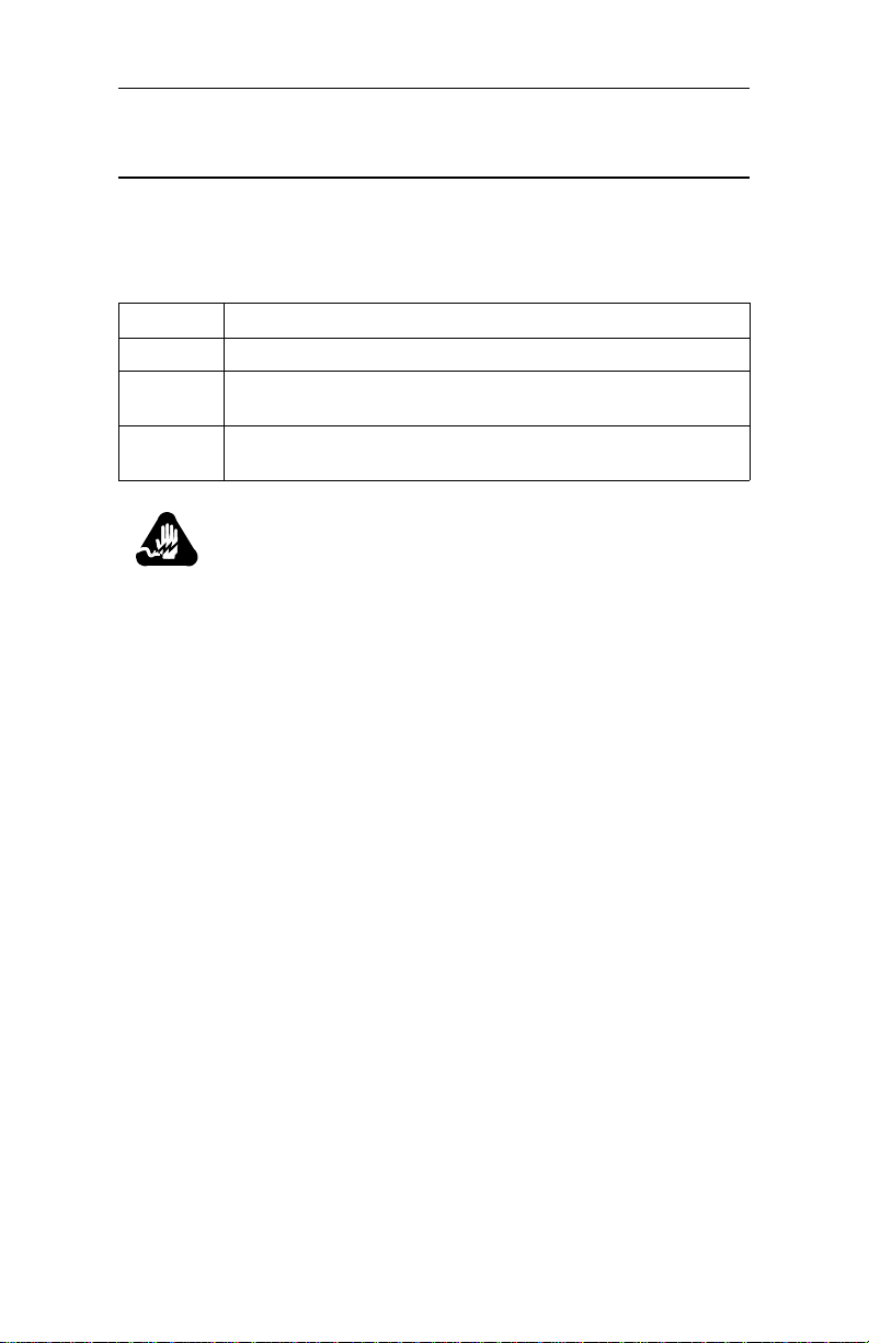
The following notices emphasize certain information in the guide:
IMPORTANT: Emphasizes significant procedural information.
Caution
Warns you against damage to software,
hardware, or data.
Mise en Garde
Une mise en garde vous fournit des
informations qui, si ell es ne sont pas observées,
peuvent se traduire par des dommages pour le
logiciel, le matériel ou les données.
vii
Page 8

3460 Fast’R
Vorsicht
Ein Vorsichtshinweis macht Sie darauf
aufmerksam, daß Nichtbefolgung zu Software-,
Hardware- oder Datenschäden führen kann.
¡Precaución!
La precaución le ofrece información, que de no
cumplirse, puede derivar en posibles daños
tanto para el software y el hardware, como para
ambos.
Warning
Warns you against physical injury.
Avertissement
Un avertissement constitue le message le plus
sérieux, indiquant que vous pouvez subir des
blessures corporelles.
viii
Warnung!
Eine Warnung ist der ernsthafteste Hinweis auf
Körperverletzungsgefahr.
¡Advertencia!
Una advertencia es un aviso importante, que le
advierte sobre la presencia de un
inminente peligro.
Page 9

3460 Fast’R
Trademarks
The following are trademarks or registered trademarks of their
respective companies or organizations.
Mark Company/Organization
AT Hayes Microcomputer Products, Inc.
Windows Microsoft Corporation
All other brand and product names are trademarks or registered
trademarks of their respective owners.
ix
Page 10

Page 11

Motorola Customer Information
If you have questions or problems, or you need assistance with
technical, sales, or billing matters, please call our Customer Support
Center:
• (800) 544-0062 from the U.S.A. and Canada
• (508) 261-0366 from other locations
To Access the Motorola World-Wide Web Site
Company and product information can be found on our Web site at:
http://www.mot.com/ING/
To Order Additional Motorola User Documentation
To order additional copies of Motorola user documentation, call
(508) 261-5933.
xi
Page 12

Page 13
Customer Response Card
Motorola would like your help in improving its product documentation. Please
complete and return this card to provide your feedback. U.S.A customers can use
the pre-paid reply envelope. All customers can fax to (508) 339-9592; Attention:
Product Documentation.
To discuss your comments with a member of Motorola documentation group,
provide telephone information at the bottom of this page. Thanks!
Your Name _________________________ ______________________
Company Name ___________________________________________
Address ________ ____________________ ____________________ __
_____________ ____________________ _________________ _______
Document Title: 3460 Fast’R User’s Guide
Part Number : T0022-01, Rev F
Please rate this manual for usability:
Excellent Good Average Below Average Poor
What did you like about the manual? _____________________________________
_________________________ ______________________________________ ____
_________________________ ______________________________________ ____
What informatio n, if any, is missing from the manual? ________________________
Cut Here
_________________________ __________________________________________
_________________________ __________________________________________
Please identify any sections/concepts that ar e unclear or explained inadequately.
_____________________________________________________________
_____________________________________________________________
Additional commen ts/suggestions. ____________ ___________________________
_________________________ __________________________________________
_________________________ __________________________________________
________________________ _________________________________
Telephone ____________ Ext. _______ Best time to call__________
International readers: please ma il this card to M U East, MS M3-30, Mo torola, In c., 20 Ca bot
Boulevard, Ma nsf ield, MA USA 02048.
Page 14

FOLD HERE
DO NOT TEAR – FOLD HERE AND STAPLE
BUSINESS REPLY MAIL
FIRST CLASS PERMIT NO. 39783 MANSFIELD, MA
POSTAGE WILL BE PAID BY ADDRESS EE
NO POSTAGE
NECESSARY
IF MAILED
IN THE
UNITED STATES
Motorola University East M3-30
20 Cabot Boulevard
Mansfield, Massachusetts 02048-1193
USA
Page 15

Chapter 1
Hardware Installation
Introduction
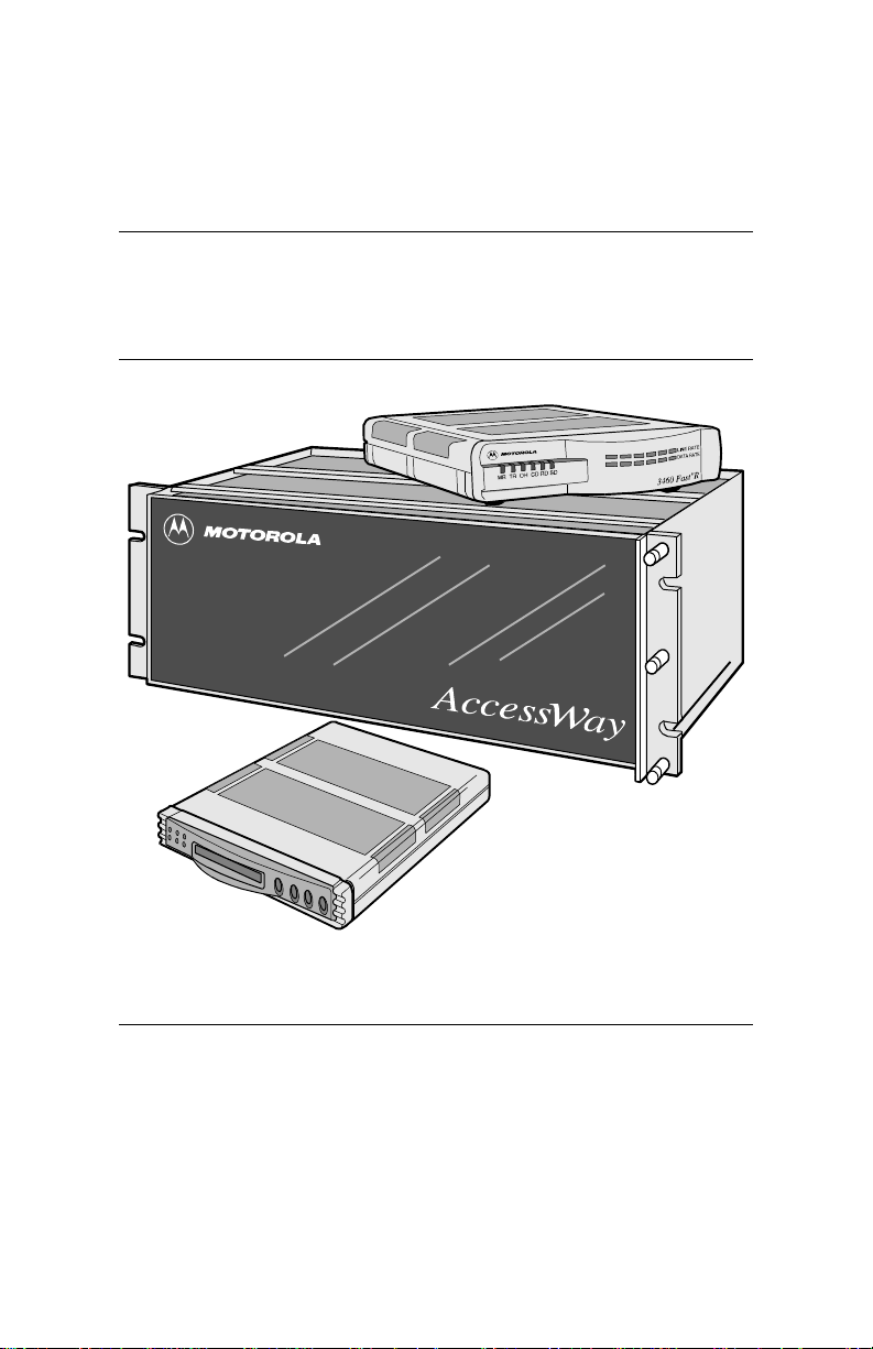
The Motorola 3460 Fast’R or 3460 Fast’R Plus modem provides
reliable data communication to meet a wide variety of networking
requirements.
The 3460’s formations include:
• A stand-alone formation with either:
— A modem that supports a two-wire leased-line or dial-line
connection
— A modem that supports a two- or four-wire leased-line
connection or a dial connection
Some stand-alone modems have an LCD display and four
menu-navigation buttons, so you can set configuration options
and monitor operation by directly accessing the modem.
• An Accessway enclosure-card formation with either:
— A pair of modems that support two-wire leased-line or
dial-line connections
— A modem that supports a two- or four-wire leased-line
connection or a dial connection
• A Vanguar d daugh tercard for mation with a modem that supports a
two- or four-wire leased-line connection or a dial connection
The 3460’s features include:
• Synchronous and asynchronous communication in one unit, with
two preset configurations for typical applications
• Automode with telephone-number linking and auto-redial
• ITU TS Compliance to V.34, V.32bis, V.32, V.29, V.27ter, V.23,
V.22, V.22bis, V.21, V.17, Bell 212A, Bell 103
• Synchronous data rates up to 33.6 KBPS and asynchronous data
rates up to 230.4 KBPS
• Industry-standard error detection and data compression
• Hayes AT and V.25bis support
1-1
Page 16

3460 Fast’R
• Automated software download and flash memory for easy
upgrades
• V.54 diagno stic test suite
• LED displays that indicate modem activity
• Light bar displays (stand-alone modem only) that indicates line,
data, and link-utilization rates
• Support for the Motorola 9000 Open Management System (OMS)
Network Management System
• Support for secondary-channel modem management
• Restoral: automatic rerouting of data traffic to the PSTN, over a
two-wire dial line, for backup of critical leased-line applications
when a leased line fails or signal quality deteriorates. Restoral is
available on units that support four-wire leased-line operation.
• Support for Fax Class 1, Class 2.0, and Group 3 fax standards, to
enable transmission and receipt of faxes at up to 14.4 KBPS
(with a fax application installed)
• LCD display and menu-navigation buttons, on some stand-alone
modems
For instructions on installing a Vanguard 3460 V.34 Daughtercard in a
Vanguard enclosure, refer to the Vanguard Daughterc a rd Installati on
Guide (Part No. T0020-02).
1-2
Page 17
3460 Fast’R
Installing a Stand-Alone Modem
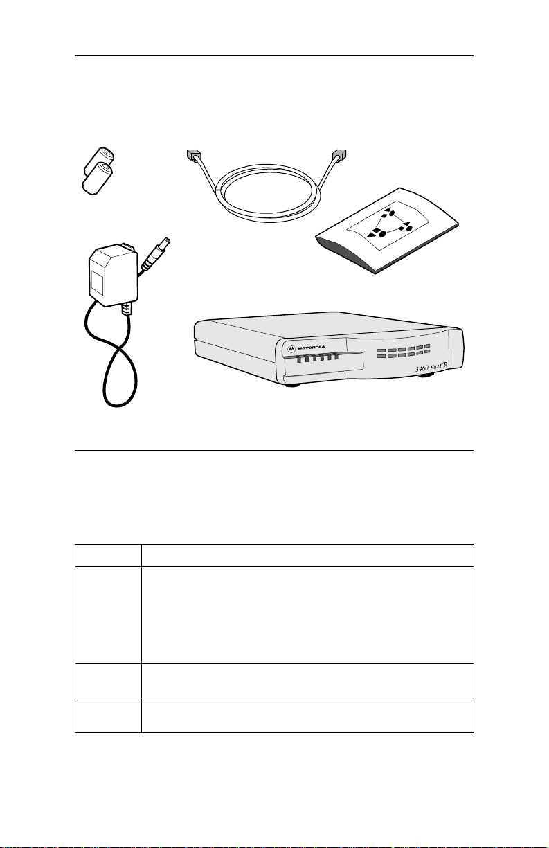
In the shipping carton, locate the items shown in Figure 1-1.
Ferrite Beads (2)
(With Some Units)
Power Transformer
RJ11 Telco
Cable
This User’s Guide
3460 Fast'R S t and-Alone Mode m
(Some modem front panels
differ from the one shown.)
Figure 1-1. 3460 Fast’R Stand-Alone Modem Parts
Installing a Stand-Alone Modem
Step Action
1. Compare the modem package cont ents to Figure 1-1. If a part is
missing, contact your nearest Motorola representative, or:
• In the U.S.A.— Motorola Customer Administration, 20 Cabot
Blvd., Mansfield, MA 02048. (5 08) 261-4745.
•Outside the U.S.A.—Motorola distributors are listed on our
Web site, at: http://www.mot.com/MIMS/ISG/
2. Plug the modem power-transformer cable into the modem’s
3. Connect a cab l e fro m a co mputer serial port to the mode m ’s
AC~ connector and then into a power supply outlet.
DTE connector .
1-3
Page 18

3460 Fast’R
Installing a Stand-Alone Modem
(continued)
Step Action
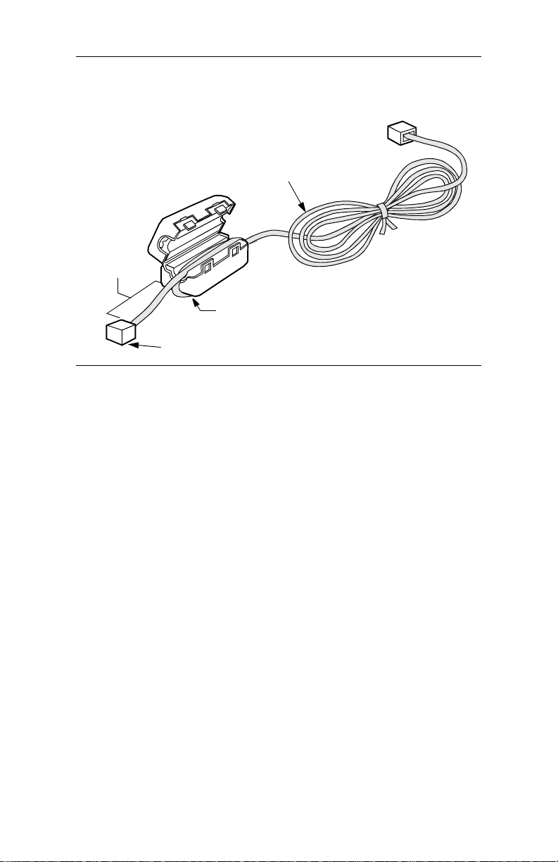
4. If ferrite beads are included with your modem, install them on
5. For two-wire leased-line or dial-line modems:
6. Set the modem power switc h to the On (1) position. The modem
7. Stand-alone modem hardware installation is complete.
both telephone cables:
a) Snugly wrap the cable once completely around the
bead (Figure 1-2).
b) Set the cable into the bead cutouts. Ensure that 2.5 to
4 cm of the cable extend from the bead (on the end you
insert into the modem connect or).
c) Snap the bead closed. You can reopen and close it to
reset the cable.
a) Plug the telephone cable into the modem’s LINE
connector (Figure 1-3) an d to the telephone wall jack.
b) To use a telephone set on the same line as the modem,
ensure that the ferrite bead (if included) is installed on
the cable; then plug it into the modem’s PHONE
connector.
For two- or four-wire leased-li ne/dial-line modems:
a) Optionally, plug an analog dial line telephon e cable
into the modem’s PHONE LINE connector
(Figure 1-3) and to the telephone wall jack.
b) Ensure that the ferrite bead (if in cluded) is insta lled on
a leased-line cable; then plug it into the modem’s
LEASE connector.
executes self-tests. A modem indicates test results as follows:
• Successful completion: MR LED steady on.
• A problem by setting LEDs in one of these ways:
— MR: slowly blinking. TR: on. OH: off. CD: off.
— MR: off. TR: on. OH: on. CD: on.
You can also check self-test completion with Fast’RVu. Select
Status, then select:
• EIA to display DCD, DTR, DSR, CTS, and RTS signal states
• Device to display rate and mode parameters that describe the
modem’s current state
Note the LED pattern. Report any problem to Motorola Support.
Go on to Chapter 2, Basic Modem Setup, or Chapter 3,
Advanced Modem Setu p.
1-4
Page 19
3460 Fast’R
Cable
2 - 4 cm
Cable Looped Once
Around Bead
To Modem Connector
Figure 1-2. Ferrite Bead Installation
1-5
Page 20
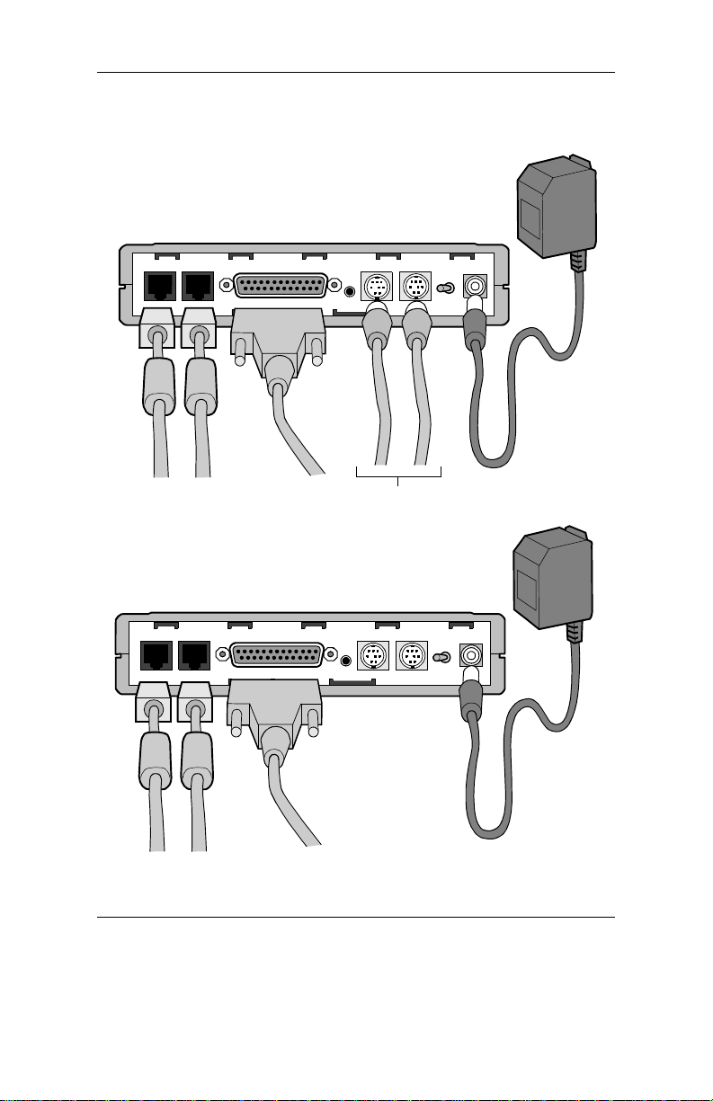
3460 Fast’R
(A) Modems that support two-wire
leased- or dial-line connections
LINE PHONE
DTE
.
Optional Fast’RV u
Connectors. See Chapter 4.
(B) Modems that support two- or four-
wire leased-line/dial-line connections
PHONE
LINE LEASE
DTE
IN
.
IN
OUT
NM
NM 1 0
Power
Transformer
AC~
I
1 0
Power
Transformer
OUT
AC~
I
Connect to Fast’RVu in either of these ways:
• With NC cables, shown in (A)
• With data cables, using logical secondary channel
Figure 1-3. Modem Rear Panel and Cable Connections
1-6
Page 21
3460 Fast’R
Safety and Operational Notices
Power Transformer
Warning
The stand-alone modem is for use with an approved power
transformer, available only from Motorola, Inc.
Avertissement
Le modem autonome doit être utilisé avec un transformateur
de courant homologué, disponible uniquement aupr ès de
Motorola, Inc.
Warnung
Das freistehende Modem ist mir einem zugelassenen,
ausschließlich von der Motorola, Inc. erhältlichen
Leistungstransformator zu verwenden.
Connecting Ports
Warning
Ports that are capable of connect ing to other apparatus are
defined as SELV. To ensure conformity with EN60950 ensure that these ports are only connected to ports of the same
type on other apparatus.
Warning
Les ports qui sont susceptibles d’être connectés à des
équipements sont désignés comme TBTS. Pour garantir la
conformité à la norme EN 60950, n’interconnecte ces ports
qu’avec des ports du même t ype sur des autres matéri els.
Warning
Anschlusse, die mit a nderen Geraten verbindet werden
konnen, sind als SELV beschrieben. Um Konformitat mit EN
60950 zu versichern, sichern Sie es, daß diese Anschlusse nur
mit den des selben Type auf anderen Geraten verbindet
werden.
1-7
Page 22

Repair
3460 Fast’R
Warning
Do not attempt to repair the modem or enclosure. They
contain no electronic components that can be serviced or
replaced by a user. Any attempt at user service of the modem
or enclosure, or ope ning of the modem, voi ds the product
warranty.
Avertissement
N’essayez pas de réparer le modem ou le boîtier. Ils ne
contiennent aucun composant électronique pouvant être
réparé ou remplacé par un usager. Toute tentative de
réparation du boîtier du 3460 F ast’R ou de l’AccessWay 16
par un usager, ou toute intervention à l’intérieur du 3460
Fast’R, annule la garantie du produit.
Warnung
Versuchen Sie nicht, das Mo dem oder sein Gehäuse z u
reparieren. Es sind keine durch den Benutzer wartungs- oder
austauschfähige Teile darin enthalten. Bei jeglichem Öffnen
oder Wartungsversuch am 3460 Fast'R bzw. AccessWay
16-Schaltkasten durch den Benutzer verfällt die
Gerätegarantie.
1-8
Page 23

Lightning
3460 Fast’R
Warning
All Motorola devices should be used in environments
designed for computers and elect ronic equipment. In areas
susceptible to lightning, take precautions to prevent
damage to electronic equipment. Contact your tel ephone
company, or an electronic accessories vendor, for information
on lightning pro tection equipment. Customers experien cing
problems caused by s urges fr om lightning have el iminated
such problems by installing appropriate surge suppressors
on power and data lines connected to Motorola devic e s.
Ave rt isse me nt
Tous les dispositifs Motorola doivent être utilisés dans des
environnements conçus pour des ordinateurs et du matériel
électronique. Dans les zones susceptibles d’être frappées par
la foudre, prenez des précauti ons pour éviter que le matériel
électronique soit endommagé. Contactez votre compagnie
téléphonique, ou un vendeur d’accessoires électroniques,
pour obtenir des renseignements concernant les systèmes de
protection contre la fo udre. Certains usagers confrontés à des
problèmes causés par des sautes de tension dues à la foudre
ont éliminé ces problèmes en installant des régulateurs de
tension appropriés sur les câbles électriques et les câbles de
données reliés aux dispositifs Motorola.
Warnung
Motorola-Geräte sind grundsätzlich in für Rechner
elektronische Anlagen vorgesehenen Umgebungen zu
und
verwenden. In unwettergefährdeten Bereichen ist jegliche
Elektronik gegen Blitzeinwirkung z
entsprechende Schutzeinrichtungen erfahren Sie von Ihrer
T elefon gesellsch aft oder eine m Elektroh ändle r. Probleme mit
Spannungsstößen durch Blitzeinwirkung lassen sich durch
Einbau von Überspannungsableitern in die zu MotorolaGeräten führenden Netz- und Datenleitungen beheben.
u schützen. Näheres über
1-9
Page 24
3460 Fast’R
Installing an AccessWay Enclosure
The AccessWay enclosure houses up to 16 Fast’R modem cards and a
power module.
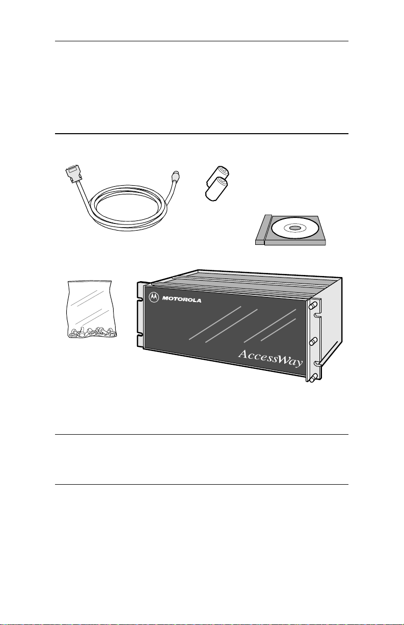
Checking AccessWay Enclosure Shipment
In the shipping carton, locate the items shown in Figure 1-4.
Ferrite Beads,
(With Some Units)
Computer Cable for Fast’RVu
(DB-25 to 8-Pin DIN)
Software & Documentation
on CD-ROM
Rack-mount Kit
AccessWay Enclosure for
Card Modems
If a part is missing, contact Motorola as described in the installation instructions. Order card modems, power cable, and telephone cables separately.
Figure 1-4. AccessWay Enclosure Shipment Contents
Site and Power Preparation
Ensure that there is sufficient cooling space around the Accessway
enclosure, according to the following specifications.
1-10
Page 25
3460 Fast’R
Cooling for One or Two Enclosures
When one or two enclosures are mounted in a rack or cabinet, one
directly above the other, with no other eq uipment directly below, natural
convection provides sufficient airflow through the enclosures.
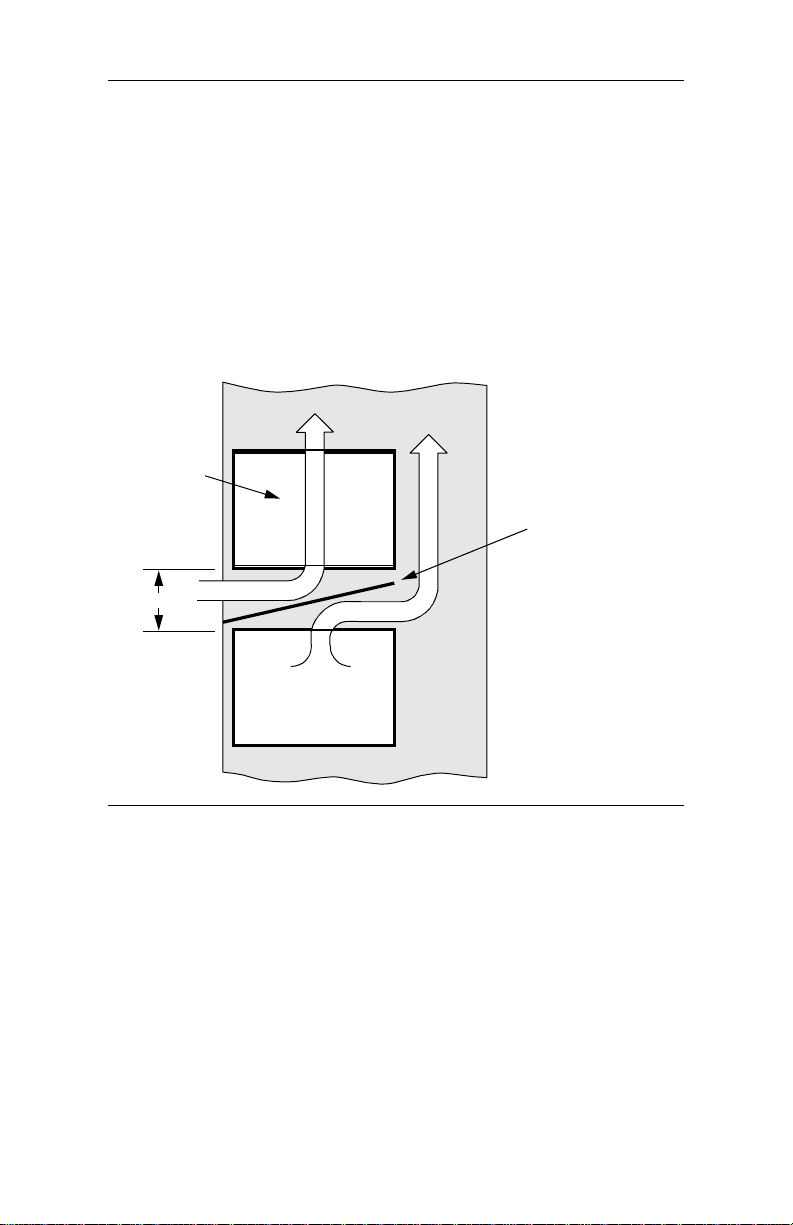
When one or two enclosures are rack-mounted with other equipment
directly below that produces rising heat, a 9 cm space is required
between the enclosure and the other equipment to exhaust hot air from
below. A deflector must be fitted into this space to avoid mixing the air
flows (Figure 1-5 ).
Airflow
Accessway
9 cm
Other Heat-
Producing
Equipment
Front of Rack
Airflow
Deflector
Rear of Rack
Figure 1-5. Cabinet Arrangement—One or Two Enclosures
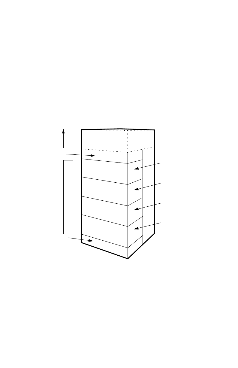
Cooling for Three or More Enclosures
When three or more enclosures are mounted in a rack or cabinet,
forced-air cooling with fans and a deflector is required.
1-11
Page 26
3460 Fast’R
Fan and Deflector Requirements
Forced-air cooling for up to four rack-mounted enclosures can be
provided by fans and a deflector, mounted below the enclosures, to
provide passive, bottom-entry rear exhaust and upward-forced, frontentry cooling air. Refer to Figure 1-6. The airflow requirement is 80
CFM (2266230 CCM).
For example, three fans rated 117 CFM (202176 CCM) at a static
pressure of 0 inches of water provide enough airflow , when cooling four
enclosures. The deflector ensures that hot air fro m equipm ent b elow th e
enclosures does not mix with enclosure-cooling air. The cabinet must
have venting at the top or rear to let exhaust air escape.
Unit 2
Fan Chassis 2
AccessWay
AccessWay
Unit 1
AccessWay
AccessWay
Fan Chassis 1
Figure 1-6. Cabinet Arrangement—Three or More Enclosures
1-12
Page 27

3460 Fast’R
Caution
Failure to comply with these requirements may result in
thermal/electrical stress that can affect reliability or cause
serious damage to components.
Avertissement
Le non respect de ces normes pourra donner lieu des
contraintes thermiques/lectriques susceptibles d’affecter la
fiabilit des composants ou de les endommager
srieusement.
Vorsicht
Nichtbefolgung dieser Vorkehrungen kann zu thermischer
bzw. elektrischer berlastung und zu Unzuverlssigkeit oder
ernsthafter Beschdigung der Bauteile fhren.
Selecting a Power Cord
The connector should meet the requirements of CEE Pub. 22, Standards
Sheet V, BS 4491, CSA C22.2, DIN 49 457, UL 498, UL 817, and VDE
0625. The entire assembly should meet all safety requirements in the
country of use. The AccessWay power cord and plug should meet the
standards in Table 1-1 and Table 1-2.
Table 1-1. Power Cord and Plug Standards - Types
Group Plug Type Plug Standard Cord Standard
1 Schuko CEE Pub. 7
2 Australian SAA3112-1981 SAA3191-1981
3 British BS 1363 BS 6500 (HD-21 HAR)
4 Danish AFSNIT 107 HD-21 (HAR)
5 Indian BS 546 HD-21 (HAR)
6 Israeli S. I. 32 HD-21 (HAR)
7a North American NEMA 5-15 (125V) SJT
7b North American NEMA 6-15 (250V) SJT
8 Swiss SEV 1011.1959 HD-21 (HAR)
HD-21 (HAR
2
)
1
1-13
Page 28

3460 Fast’R
Table 1-1. Power Cord and Plug Standards - Types
Group Plug Type Plug Standard Cord Standard
9 Permanently
connected
10 China GB 2099 GB 5023
1
Cord size should be 0.75 mm or 18 AWG minimum.
2
Cords listed as HAR should bear the marking <HAR>
EN60950 HD-21 (HAR)
Table 1-2. Power Cord and Plug Standards - Countries
Group Country
1 Austria, Algeria, Azerbaijan, Belarus, Belgium, Bolivia, Bulgaria,
Chile, Czech Republic, Croatia, Egypt, Estonia, Finland, France,
Germany, Greece, Hungary, Indonesia, Jordan, Khazakstan,
Kyrgyzstan, Latvia, Lebanon, Lithuania, Morocco, Netherlands,
Norway, Poland, Portugal, Romania, Russia, Slovakia, Slovenia,
Spain, Sweden, Tunisia, Turkey, Ukraine, Uruguay, Uzbekistan
2 Argentina, Australia, China, New Zealand
3 Bahrain, Botswana, Cyprus, Ghana, Hong Kong, Ireland, Kuwait,
Malaysia, Oman, Qatar, Sin gap ore, Unite d Arab Emirates, United
Kingdom
4Denmark
5 India, Pakistan, South Afr ica, Sri Lanka
6 Israel
7a Belize, Bermuda, Brazil, Canada, Colombia, Costa Rica, Ecuador,
El Salvador, Guatemala, Honduras, Jamaica, Japan, Mexico,
Nicaragua, Panama, Peru, Philippines, Puerto Rico, Saudi Arabia,
Taiwan, Trinidad, Venezuela, United States of America
7b 230 V Applications: Canada, Korea, Thailand, United States of
America
8 Switzerland
9Norway, Sweden
10 China
1
1-14
Page 29
3460 Fast’R
Installing the Enclosure in an Equipment Rack
Place the AccessWay enclosure in a 19-inch (48.3 cm) EIA/RETMA
equipment rack or cabinet.
Installing an AccessWay in an Equipment Rack
Step Action
1. Slide the enclosure into the equipment rack.
2. Secure the enclosure brackets to the equipment rack, using the
3. Ensure that the enclosure is ven tilated and cooled according t he
hardware provided in the rack-mount kit.
guidelines in this chapter.
Warning
All Motorola devices should be used in environments
designed for computers and electronic equipment. In areas
susceptible to lightning, take precautions to prevent damage
to electronic equipment . Contact your telephone company, or
an electronic accessories vendor, for information on lightning
protection equipment. Customers experien cing problems
caused by surges from lightning have eliminated such
problems by installing approp ria te surge suppressors on
power and data lines connected to Motorola devices.
Avertissement
Tous les dispositifs Motorola doivent être utilisés dans des
environnements conçus pour des ordinateurs et du matériel
électronique. Dans les zones susceptibles d’être frappées par
la foudre, prenez des précauti ons pour éviter que le matériel
électronique soit endommagé. Contactez votre compagnie
téléphonique, ou un vendeur d’accessoires électroniques,
pour obtenir des renseignements concernant les systèmes de
protection contre la fo udre. Certains usagers confrontés à des
problèmes causés par des sautes de tension dues à la foudre
ont éliminé ces problèmes en installant des régulateurs de
tension appropriés sur les câbles électriques et les câbles de
données reliés aux dispositifs Motorola.
1-15
Page 30

3460 Fast’R
Warnung
Motorola-Geräte sind grundsätzlic h in für Rechner und
elektronische Anlagen vorgesehenen Umgebungen zu
verwenden. In unwettergefährdeten Bereichen ist jegliche
Elektronik gegen Blitzeinwirkung zu schützen. Näheres über
entsprechende Schutzeinrichtungen erfahren Sie von Ihrer
T elefon gesellsch aft oder eine m Elektroh ändle r. Probleme mit
Spannungsstößen durch Blitzeinwirkung lassen sich durch
Einbau von Überspannungsableitern in die zu MotorolaGeräten führenden Netz- und Datenleitungen beheben.
Cabling an AccessWay Enclosure
Connect cables to the AccessWay as foll ows. See Figures 1-7 and 1-8.
Cabling an AccessWay Enclosure
Step Action
1. In enclosures with mass-termination telephone connectors,
attach ferrite beads (Figure 1-7), if they are supplied, to the
multi-line cables from the telephone service outlets to the two
mass-termination connectors on the AccessWay rear panel.
Attach the beads within 2 - 4 cm of the AccessWay panel. Pass
the cable straight through the bead, without turns.
Note: The AccessWay mass-termination backplane does not
support two- or four-wire leased-line/dial-line cards. To mix
these cards with two-wire leased-line or dial -l ine cards, the
AccessWay must have the RJ-11 backplane.
2. Ensure that telephone lines are configured and connected to the
All cables should be emissions-shielded.
service provider’s outlet or closet connection.
1-16
Page 31

3460 Fast’R
Cabling an AccessWay Enclosure
(continued)
Step Action
3. If you plan to c onfigure modems by issuing commands:
•Directly to each modem: connect a shielded cable from a
computer’s serial port to a modem DTE connector. (After
configuring a modem, move the connector to another modem.)
• With Fast’RV u over a direct cable connection, or with a locally
attached Motorola network management system (NMS):
connect the shielded NMS cable from the computer or NMS’s
serial port to the enclosure’s NM IN connector. In enclosures
with mass-termination telephone connectors, install a ferrite
bead on each NMS cable, near the AccessWay panel. Pass the
cable through the bead twi ce, with one full turn.
• With Fast’RVu over a secondary-channel connection, you do
not need a special cable connection.
4. Optionally, on DC powered enclosures, install a second DC
5. Connect the power cable from the AccessWay rear panel to a
All cables should be emissions-shielded.
power module. Installation is described later in this chapter.
power source. The enclosure is factory-configured for one
power input type: AC or DC. Your power source must match.
Figure 1-7 shows how to attach a ferrite bead to a mass-termination
multi-line telephone cable.
Cut-out
To AccessWay
2 - 4 cm from bead to
AccessWay unit
Figure 1-7. Ferrite Bead Installation
Cut-out
To Cable Clamp
Ferrite Bead
1-17
Page 32

3460 Fast’R
Upper (A) Telephone
Connectors, Slots 1-16
Modem Required in This
Slot for Management by
NMS or Fast’RVu
IN OUT
Computer
Connectors
Lower (B) Telephone
Power Cord
Connectors, Slo ts 1-16
Rear View , AccessWay Enclosure (Shown With Dual-Modem Cards, Individual
RJ-11 Connectors, and AC Power)
Figure 1-8. Cabling an AccessWay Enclosure
Cabling One or More Enclosures to a Computer
You can connect up to four enclosures together and use Fast’RVu to
manage all the modems.
Cabling Enclosures Together for Fast’RVu
Step Action
1. Ensure that enclosures are securely installed in equipment racks.
2. Assign addresses to enclosures by setting the DIP switch on each
enclosure rear panel. Refer to Table 1-3.
3. Cable the enclosures’ NM OUT (or NC OUT) and NM IN
(NC IN) connectors together (Figure 1-9).
4. Cable a computer’s serial communications (COM) port to the
first enclosure’s NM IN connector.
5. Refer to Chapter 4 for instructions on using Fast’RVu.
1-18
Page 33

INOUT
First Enclosure (Loc ations 1-32)
INOUT
Second Enclosure (Loc ations 33-64)
3460 Fast’R
Computer
Off On
1
2
Off On
1
2
Off On
1
INOUT
Third Enclosure (L ocations 65-96)
2
Off On
1
INOUT
Fourth Enclosure (Locations 97-128)
2
Figure 1-9. Cabling AccessWay Enclosures Together
1-19
Page 34

3460 Fast’R
Modem Addresses in Multiple-Enclosure
Configurations
When you cable enclosures together, their mod em slots are assigned the
following addresses. Slot numbers and modem locations are marked on
the enclosure rear panel. Set each enclosure to a different address.
Table 1-3. Modem Addresses in AccessWay Enclosure
The Enclosure
With This DIP
Setting
(Fig. 1-9)...
DIPs =ON/ON 1 through 32 1 = Slot 1 Position A
DIPs =ON/OFF 33 through 64 33 = Slot 1 Position A
DIPs =OFF/ON 65 through 96 65 = Slot 1 Position A
DIPs =OFF/OFF 97 through 128 97 = Slot 1 Position A
A single-modem card supports a two- or four-wire leased-line connection in
Position A, or a dial-line connection in Position B.
Has These
Modem-
Addresses...
Assigned to These
Locations:
2 = Slot 1 Position B
3 = Slot 2 Position A
4 = Slot 2 Position B
. . .
32 = Slot 16 Position B
. . .
64 = Slot 16 Position B
. . .
96 = Slot 16 Position B
. . .
128 = Slot 16 Position B
With Fast’RVu, select a modem in an AccessWay enclosure as follows.
1. In the Fast’RVu main window, select ENCLOSURE LOCATION.
2. In an option window, specify the modem location. Example: Select
Enclosure (Nest) with DIPS at ON/ON; Slot 1; Position A; which is
Modem Address 1:
1-20
Page 35

3460 Fast’R
Installing/Removing Modem Cards
Installing a Modem Card
Y o u can install 3460 Fast’R cards in an AccessWay while it is operating.
Modem A
Modem B
Two-Wire Leased- or
Dial-Line Dual-Modem Card
Four-Wire Leased-Line/Two- or FourWire Dial-Line Modem Card
Figure 1-10. 3460 Fast’R Modem Cards
Installing a Modem Card in an AccessWay
Step Action
1. Loosen the enclosure front door screws. Open the door.
2. Flip the modem card’ s ejecto r ta bs (Fig ure1-11 ) ap art. Slid e the
3. If you plan to use Fast’RV u or a Motorola network management
card into a slot’s guide rails. Press the tabs until it is seated
firmly and the tabs are against the rail. Ensure tha t the card fron t
panel is flush with the power module front panel.
system, install a card in Slot 9. A card must be present in Slot 9
to transfer network control information to and from modems.
1-21
Page 36

3460 Fast’R
Installing a Modem Card in an AccessWay
(continued)
Step Action
4. If your AccessWay has:
• Individual telephone cable connectors , connect cables from
the telephone service o utlets to each modem connector.
The upper connector serves:
— Two- and four-wire leased line modems, on
four-wire leased line cards
— Modem A, on dual-modem cards
The lower connector serves:
— Dial-line connections, on four-wire leased line cards
— Modem B, on dual-modem cards.
• Mass-termination connectors, you should have two multi-line
cables from the telephone service outlets to the two masstermination connectors on the AccessWay rear panel, already
connected.
• Note: Mass-termination is not compatible with the two- or
four-wire leased-line/dial-line modem card.
The upper connector serves Modem A on dual-modem cards.
The lower connector serves Modem B on dual-modem cards.
Refer to the 3460 Fast’R Reference Guide for cable pin-outs.
5. A modem begins a self-test sequence when power is applied. A
6. Connect a cable from a compu t e r se ri al port to the appropriate
7. To configure modems for operation, go on to Chapter 2.
modem indicates test results as follows:
• Successful completion: MR LED steady on.
• A problem by setting LEDs in one of these ways:
— MR: slowly blinking. TR: on. OH: off. CD: off.
— MR: off. TR: on. OH: on. CD: on.
You can also check self-test completion with Fast’RVu. Select
Status, then select:
• EIA to display DCD, DTR, DSR, CTS, and RTS signal states
• Device to display rate and mode parameters that describe the
modem’s current state
Note the LED pattern. Report any problem to Motorola Support.
Modem DTE connector on the enclosure rear panel.
1-22
Page 37

Slot 9
3460 Fast’R
Card-Ejector Tabs
Front of Enclosure
Hold a card by its front rail and tabs.
Slide it along the card guide rails.
Figure 1-11. Installing a Modem Card in an AccessWay
Removing a Modem Card
Y o u can remove modem cards from an AccessWay while it is operating.
Removing a Modem Card from an AccessWay
Step Action
1. Press the card ejector tabs apart (Figure 1-11).
2. Hold the card by its edges. Slide it out along the guide rails.
1-23
Page 38

3460 Fast’R
Power Modules
This section provides basic information about AC and DC power
modules for the AccessWay enclosure.
Warning
T o avoid the po ssibility of electric al shoc k, remov e the power
cord before servicing the power module.
Avertissement
Pour éviter tout risque d’él ectrocution, débrancher le cordon
électrique avant de réparer le module d’alimentation.
Warnung
Um möglichen elektrischen Schlag zu vermeiden , i s t vor
Wartungsarbeiten am Netzmodul das Stromkabel
abzustecken.
AC Power Module
Refer to the 3460 Fast’R Reference Guide for instructions on removing
and servicing an AC power module.
1-24
Warning
This product employs double-pole/neutral fusing. When fuses
are replaced, they must be replaced with fuses of the same
type and rating.
Ave rti sse ment
Ce produit utilise des fusibles bipolaires/neutres. Lorsque les
fusibles doivent être remplacés, ils doivent l’être par des
fusibles de même type et de même calibre.
Warnung
Dieses Gerät verwendet zweipolige neutrale Absicherung.
Beim Auswechseln der Sicherungen sind diese mit solchen
des gleichen Typs und gleicher Leistung zu erset zen.
Page 39

3460 Fast’R
DC Power Module
The AccessW ay -48 VDC-powered enclosure provides:
• Optional independent dual DC power module operation
• Optional indepe ndent dual DC power source connections
• Relay contacts for connection to an alarm monitoring device
Connecting to DC Power Supply
Y o u may connect the AccessWay to a single DC power source, or to two
separate sources (to enable the AccessWay to continue operating if one
power source fails).
Connecting the AccessWay to DC Power Supply
Step Action
1. Obtain wire that is rated AWG 20, stranded, 300 V insulation.
2. Optionally: remove the AccessWay power terminal block from
3. Strip several lengths of wire to 0.3” (7 mm) from the ends. Use
4.
its connector on the rear of the AccessWay unit. It is easier to
work with the bloc k when it is removed.
them to make the follo win g co nn e ct ion s. Ttigh te n con nec tors so
they are snug.
Caution
Ensure that the DC power source is turned off
before making connections.
To operate with single or dual DC battery or power source,
connect:
a) The AccessWay VA terminal to the battery’s
- (negative) terminal
b) One AccessWay COM terminal to the battery’s
+ (positive) terminal
c) The AccessWay CH GND terminal to frame ground
5. For operation with dual DC battery or power sources, connect:
a) The AccessWay VB terminal to the second battery’s
- (negative) terminal
b) The remaining COM terminal to the second battery’s
+ (positive) terminal
1-25
Page 40

3460 Fast’R
Connecting the AccessWay to DC Power Supply
Step Action
6. Optionally, connect a remote alarm monitoring device to th e
AccessWay, to alert you to a fault in the DC output voltage.
a) Determine whether yo u want the alarm relay contacts
open or closed when AccessWay output voltages are
within normal operating range. The default setting is
Normal Open.
b) Optionally, reverse this setting: at the front of the
AccessWay, loosen a power module’s captive screws
and pull the power module out of the AccessWay. Set
the jumper to the Normal Closed position
(Figure 1-12). Replace the power module in the
AccessWay. Tighten the captive screws that secure it.
c) Connect two lengths of wire from the alarm monitor
device terminals to the ALARM 1 terminals on the
back of the AccessW ay.
7. If you disconnected the power terminal block from the rear of
the AccessWay unit, replace it.
8. Attach the cable clamp (Figure 1-13; provided with the
AccessWay) to the wire bundle at the rear of the AccessWay.
Leave a service loop of at lea s t 8 cm between the clamp and t he
terminal block, and secure the clamp to the screw at the left of
the terminal block.
Ensure that any strain is relieved from the cable terminals, and
that the power terminal block is easily accessible should you
need to remove it quickly in an emergency.
9. Apply DC power to the AccessWay.
Verify that the LEDs near the bottom of the power module(s) are
lit. The LEDs indicate the presence of input voltage and the
status of output voltage.
(continued)
1-26
Page 41

Captive
Screws
3460 Fast’R
Power Module Enclosure
Open
Normal
Closed
Figure 1-12. Power Module Alarm Circuit Switches
1-27
Page 42

Cable Clamp
3460 Fast’R
Terminal Block
2.5-4 cm
Tie Wrap
Figure 1-13. AccessWay Terminal Block and Cable Support
Tip for Power Module Setup
When equipping an AccessWay that has two power modules for remote
alarm monitoring, you may attach the power modules to separate alarm
monitor devices.
1-28
Page 43

3460 Fast’R
Installing a Second DC Power Module
You can install a second DC power module, while the AccessWay is
operating, as follows.
Installing a Second DC Power Module
Step Action
1.
Warning
The AccessWay enclosure power module
should be installed and removed only by a
trained service per son.
Avertissement
Le module d’alimentation électrique de
l’enceinte AccessWay doit être installé et
retiré par un réparateur expérimenté.
Warnung
Ein- und Ausbau des AccessWay
Schaltschranks ist von einem geschulten
Wartungstechniker vorzunehmen.
2. Remove the blank panel that covers the right power module slot
3. Slide the second power module into the right AccessWay power
4. Optionally, connect a remote alarm monitoring device to th e
5. Verify that the LEDs on the power modules are lit. The LEDs
by loosening the screws at the top and bottom (Figure 1-14).
module slot. Ensure that its front rail is flush with the adjacent
power module rail.
Tighten the power module screws.
AccessWay ALARM 2 terminals, to alert you to a fault in the
DC output voltage. To do so, refer to the “Connecting the
AccessWay to DC Power Supply” section on page1-25.
indicate the presence of input voltage and the status of output
voltage.
1-29
Page 44

3460 Fast’R
Slot 9
Power Module
Location
(Two Slots)
Right Power Module Slot
Left Power Module Slot
Front of Enclosure
Figure 1-14. Dual DC Power Module Locations
1-30
Page 45

3460 Fast’R
Installing a Modem Daughtercard, Vanguard Enclosure
The Vanguard 3460 V.34 Daughtercard card operates in Vanguard
enclosures. For instructions on installing and removing Vanguard
Daughtercards, refer to the Vanguard Daughtercard Installation Guide
(Part. No. T0020-02).
IMPORTANT: When using a network-management application, such
as Fast’RVu, with Vanguard 3460 V.34 Daughtercards, always assign
the address Enclosure 1, Slot 9, Modem B to the daughtercard.
The daughtercard always presents itself as a master modem in Slot 9 to
the network-management application, regardless of its location.
Set-Up
The Vanguard 3460 V.34 Daughtercard default option set uses an
asynchronous protocol. Howev er, the 3460 Daughtercard does not have
a computer port, so it cannot be cabled directly to a personal computer.
T o con figur e the 3460 Daughtercard, the prefer red metho d is to conn ect
a personal computer to the modem card network-management port, and
use Fast’R Vu to set options. Or, to configure for async applications only,
set the modem’s Pass Through option. To do this, establish a call from
one Vanguard port (e.g., a CTP or PAD) to the 3460 Vanguard
daughtercard port, and echo AT commands through to the modem.
1-31
Page 46

Page 47

Chapter 2
Basic Modem Setup
Introduction
To operate the modem using mostly pre-configured options (an option
set), follow the instructions here. To set advanced options, follow the
instructions in the next chapter.
Before You Start
To get started, you’ll need:
• A computer, cabled to the modem
• A communications program, which may be:
— A general-purpose prog ram to set fax options and dial into
an on-line service, using asynchronous (async) protocols
— A remote control program to operate a host computer or
access a host network, using synchronous (sync) or async
protocols
(You do not need a communications program to configure a
modem that has the four-button/LCD front panel.)
If you don’t know which t ype of communi cations you’l l use, check with
your network administrator.
Vanguard Daughtercard Setup
The Vanguard 3460 V.34 Daughtercard’s default option set uses an
async protocol. However, the 3460 Daughtercard does not have a
computer port, so it cannot be cabled directly to a personal computer.
T o configure th e 3460 Daug htercard, connect a p ersonal computer to the
modem card network-management port, and use Fast’RVu to set
options. Or, to configure for async applications only, set the modem’s
Pass Through option. To do this, establish a call from one Vanguard port
(e.g., a CTP or PAD) to the 3460 Vanguard daughtercard port, and echo
AT commands through to the modem.
2-1
Page 48

3460 Fast’R
Asynchronous Operation
Entering Commands to the Modem
If you use a communications program to enter commands: the
commands shown here are typical AT commands, but communicationsprogram command syntaxes vary, so use this procedure only as a guide.
If your modem has the four-button/LCD user interface, you can use the
menu-tree commands to enter information. Refer to Appendix D for
details.
Setting Up for Asynchronous (Dial) Operation
Basic Setup for Async Dial-Up Operation
Step Stage
1.
Run a communications program. Assign the modem to one of the
computer’s serial communicati ons (COM) ports.
2.
Optionally: store one or more telephone numbers in the modem. To
enter a number, use this command :
AT&Zn,x<CR>
where n is a Phonebook location and x is the telephone number.
2-2
3.
Optionally, enter a default initialization string. Example:
AT&F&V1*EC1S0=1
4.
Optionally: set security options. See the 3460 Fast’R Reference
Guide. Security options include:
• Password Verification on Connection
• Callback V erificatio n and Dial Restriction
• Configuration/Phone Number Access Restriction
Page 49

3460 Fast’R
Leased-Line Synchronous Operation
Set up a modem for leased line operation wi th a synchronous pro tocol as
follows. Using a special remote control program to operate a host
computer or access a host network usually requires a synchronous
protocol. Communications-program commands vary, so use this
procedure only as a guide.
Basic Setup for Sync Leased-Line Operation
Step Stage
1.
Run your communications program. Assign the modem to one of
the computer’s serial communications (COM) ports.
2.
The modem is pre-set to Option Set 1. To set it to Option Set 2, run
your communi ca tions program, and issue the ATZ2 command.
3.
For information on setting custom configuration options, refer to
Chapter 3, Advanced Modem Setup.
2-3
Page 50

3460 Fast’R
Fax Setup on Windows
To use the modem’s fax functions, you must logically install the
modem. This procedure assumes the modem is already functional for
non-fax data, and that Release 4.0 software is installed in the modem.
You can download Release 4.0 from the Motorola website.
This procedure is for Windows. For Macintosh computers, set up th e fax
application for a generic Class 1 or Class 2.0 modem.
Installing a Modem on a Windows Computer
Step Stage
1)
Use a web browser to connect to the the Motorola Transmission
Products page:
http://www.mot.com/networking/products/tran.html
Download the 3460.inf file to your computer.
2)
In Windows, open the Modems Control Panel.
In the Modems Properties window, select Add.
Follow the directions that appear, and select:
• In the Install New Modem window, select “Don’t detect my
modem; I will install it from a list.”
• In the Install New Modem window, select “Have Disk;” browse to
the location where you stored the 3460.inf file.
•In the Install New Modem window, highlight Motorola under
Manufacturer s, an d 34 60 Fast’R under Mode ls .
• In the Install New Modem window, select the communications
(COM) port to which the modem cable is attached.
2-4
3)
Windows installs the modem.
4)
In the Dialing Properties window, enter your teleph one information.
Page 51

3460 Fast’R
Installing a Modem on a Windows Computer
Step Stage
5)
Install and run a fax application.
Enter your User Setup/Branding information to comply with
country communi cations regulations (Appendix A).
If the application requ ire s it, sp ecify t hat the 3460 Fast’R Modem is
the active modem, and whether to use it as a Class 1 or Class 2.0
modem. (Most fax servers require Class 2.0.)
Optionally: set other fax modem parameters.
6)
Optionally, send a test fax. If there is a problem, refer to the
Frequently Asked Questions on th e Mo torola ING Support web
page:
http://www.mot.com/networking/support/faqs/
2-5
Page 52

Page 53

Chapter 3
Advanced Modem Setup
Vanguard Daughtercard Setup
The Vanguard 3460 V.34 Daughtercard’s default option set uses an
async protocol. However, the 3460 Daughtercard does not have a
computer port, so it cannot be cabled directly to a personal computer.
T o configure th e 3460 Daug htercard, connect a p ersonal computer to the
modem card network-management port, and use Fast’RVu to set
options. Or, to configure for async applications only, set the modem’s
Pass Through option. To do this, establish a call from one Vanguard port
(e.g., a CTP or PAD) to the 3460 Vanguard daughtercard port, and echo
AT commands through to the modem.
3-1
Page 54

3460 Fast’R
Modem Configuration and Commands
What is the Configuration?
The modem configuration is the complete current set of param e ter
options, which tell the modem how to function. For example, the
Modulation Mode param e ter options specify which mode is used in
data transmission—option 0 for V.34 Auto, and so on.
The modem operates in accordance with:
• The current parameter options
• AT commands, entered from a computer with communications
software
• Network-management commands, received from a Motorola
NMS or Fast’RVu
AT and NMS commands can temporarily override configured options.
Issuing AT Commands
When the modem is in Command Mode or Escape Mode it accepts AT
commands. The modes are similar, but:
• In Command Mode, the modem is not connected to a remote
modem
• In Escape Mode, the modem is connected to a remote modem
Communication between the computer and the modem requires a
common command interface, such as the AT command set. Typically,
you use communications software on the computer, such as
HyperTerminal, and the modem uses its Automatic Calling Interface
(ACU).
AT commands consist of the letters AT followed by characters and
symbols. (The A/ and +++ commands do not include the letters AT.)
Issuing Network Management Commands
You enter network management commands from network management
software. The 3460 Fast’R modem accepts commands from:
• Motorola Fast’RVu software (see Chapter 4)
• Motorola 9000 NMS software (see NMS documentation)
3-2
Page 55

3460 Fast’R
What Are Option Sets?
Option sets are predefined configurations. The modem comes with two
option sets. You can either:
• Operate the modem with one of these option sets
• Build on an option set with custo m options
Option sets do not include such site-specific parameters as telephone
numbers, which you must enter and save.
3-3
Page 56

3460 Fast’R
Managing Option Sets
The modem is pre-set with Option Set 1 as the active configuration.
• For asynchronous application protocols, build on Option Set 1
with any custom or site-specific parameter options
• For synchronous and leased-line application protocols, build on
Option Set 2 with any custom or site-specific parameter options
Select one of the following procedures to customize an option set. The
AT commands you need are listed in Table 3-1 and Table 3-2.
Selecting and Customizing Option Set 1
Manage an asynchronous modem configuration as follows.
Configuring a Modem for Async Operation
Step Stage
Issue the ATZ1 command1 to load Option Set 1.
1.
Optionally, set custom parameter options.
2.
If you set any options in Step 2, issue the AT&W1 command to save
3.
the configuration as Option Set 1. (Refer to Table 3-1.)
Issue the AT&Y1 command to make the modem use Option Set 1 at
4.
subsequent power-ups. Option Set 1 is active.
1
You can set options and issue commands in either of these ways:
• By issuing AT commands through a communications application
• With Fast’RVu (see Chapter 4)
Fast’RVu is especially useful for copying configurations to multiple modems.
3-4
Page 57

3460 Fast’R
Selecting and Customizing Option Set 2
Manage a leased-line synchronous modem configuration as follows.
Configuring a Modem for Leased-Line Sync Operation
Step Stage
Issue the ATZ2 command to load Option Set 2 (if it is not already
1.
active).
Press the Off-line Configuration (OLC) button for three seconds.
2.
The modem loads factory-default Option Set 1 to active memory
and enters comman d mode.
Issue the ATZ2 command to permit changes to Option Set 2. (The
3.
AT ACU remains active so that you can modify the configuration.)
Optionally, set custom parameter options by issu ing AT commands.
4.
(Table 3-1.)
If you set any options in the previous step, issue the AT&W2
5.
command to save the custom configuration as Option Set 2.
Issue the AT&Y2 command to make the modem use Option Set 2 at
6.
subsequent power-ups.
Press the OLC button for three seconds.
7.
The modem loads Option Set 2 into active memory and exits
command mode. Option Set 2 is in effect.
3-5
Page 58

3460 Fast’R
Option-Set Parameter Default Options
This section lists the pre-configured option-set parameter options.
Table 3-1. Option-Set Default Options
Pre-Configured Default Option
Command
Async Echo ATE1=On ATE1=On
Result Code ATQ0=Enable ATQ0=Enable
Result Form ATV1=Verbose ATV1=Verbose
Longspace Disconnect ATY1=On ATY0=Off
DCD Control AT&C0=High AT&C1=Normal
DTR Control AT&D2=Disconnect AT&D0=High
Line AT&L0=Dial AT&L1=2W Lease
AT Form AT&M0=Async AT&M1=Sync Data
CTS Control AT&R0=Async/Sync AT&R1=Normal
Remote Access AT&RA1=On AT&RA1=On
DSR Control AT&S0=High AT&S1=Normal
Clock AT&X0=Internal AT&X0=Internal
ACU Protocol AT
Adaptive Rate AT
V.34 Asymmetric Rate AT*AR1=On AT*AR1=On
Answer Restoral AT*AS0=LL FAIL AT*AS0=LL FAIL
Break Handling AT
Mode AT*CA0=Orig AT*CA0=Orig
Direct Mode Async
Character Length
Connect Message AT
Default Dial AT *DA0=Off AT*DA0=Off
DTE (Terminal) Rate AT*DE23=Auto AT*DE23=Auto
Lease to Dial
Threshold
Parameters and opt ions shown shaded gray vary by country. For details, refer
to Appendix B of the 3460 Fast’R Reference Guide.
1
Parameter option does not affect normal operation.
(Asynchronous)
*AC1= AT AT*AC0=None
*AP1=On AT*AP1=On
*BK0=Destructive AT*BK0=Destructive
AT*CL2=10 bits AT*CL2=10 bits
*CM0=DTE Rate AT*CM0=DTE Rate
AT*DI0=Low/Fast AT*DI0=Low/Fast
Option Set 1
Option Set 2
(Synchronous)
1
1
1
1
1
1
1
3-6
Page 59

3460 Fast’R
Table 3-1. Option-Set Default Options
(continued)
Pre-Configured Default Option
Command
Hold Dial Line AT*HD0=Off AT*HD0=Off
Dial to Lease
Threshold
DTR Delay ATS2 5= 5 ATS 25 =5
Flow Control AT
Low Speed AT*LS0=Bell AT*LS0=Bell
PSTN Signaling AT
Modulation Mode AT
Minimum Rate AT
AT Message AT
Maximum Rate AT
Overspeed AT*OS0=1% AT*OS0=1%
Parity AT*RP0=V.25
Restoral Initiation/
Termination
Restoral Auto-Redial AT
RTS Control AT
Retrains AT*RT2=High BER AT*RT2=High BER
Test Restoral AT *TR0=Off AT*TR0=Off
Data Transfer Mode AT
Reliable Message AT
EC AT*EC0=V.42 AT*EC0=V.42
DC AT*DC1=On AT*DC1=On
Delay Disconnect AT*DB0=Off AT*DB0=Off
No ACU Form AT*DM0=Async
V.25 Character AT*VC0=ASCII
V.25 Form AT*VF0=Bitsync
Parameters and opt ions shown shaded gray vary by country. For details, refer
to Appendix B of the 3460 Fast’R Reference Guide.
1
Parameter option does not affect normal operation.
(Asynchronous)
AT
*LE0=Off AT*LE0=Off
*FL3=RTS/CTS AT*FL3=RTS/CTS
MD1=On AT*MD1=On
*
MM0=V.34 Auto AT*MM0=V.34 Auto
*
MN1=300 AT*MN1=300
*
MS1=Before CD AT*MS1=Before CD
*
MX17=33.6 AT*MX17=33.6
*
1
AT*REn=Off AT*REn=Off
*RR0=Disable AT*RR0=Disable
RS1=High AT*RS0=Normal
*
SM3=Auto-
*
Reliable
XC2=Off AT*XC0=Off
*
1
1
1
Option Set 1
Option Set 2
(Synchronous)
AT*RP0=V.25
AT*SM0=Direct
AT*DM1=Sync
AT*VC0=ASCII
AT*VF0=Bitsync
1
1
1
1
1
1
1
1
3-7
Page 60

3460 Fast’R
Table 3-1. Option-Set Default Options
(continued)
Pre-Configured Default Option
Command
Sync Idle AT*V11=Char
V.25 Response AT*VR1=V.25bis
Parameters and opt ions shown shaded gray vary by country. For details, refer
to Appendix B of the 3460 Fast’R Reference Guide.
1
Parameter option does not affect normal operation.
(Asynchronous)
1
1
Option Set 1
Option Set 2
(Synchronous)
AT*V11=Char
AT*VR1=V.25bis
1
1
AT Commands for Modem T a sks
Table 3-2. AT Commands to Manage Option Sets
To...
Load Option Set 1 into modem memory ATZ0 or ATZ1
Load Option Set 2 into modem memory ATZ2
Specify that the modem loads Option Set 1 into
memory at subsequent power-ups
Specify that the modem loads Option Set 2 into
memory at subsequent power-ups
Specify that the modem loads the last-saved option
set (AT&W) at subsequent power-ups
Save the active configuration into Option Set 1 AT&W0 or AT&W1
Save the active configuration into Option Set 2 AT&W2
Enter This
Command:
AT&Y1
AT&Y2
AT&Y0
AT Action Commands
AT commands for performing basic functions are as follows.
Table 3-3. AT “Action” Commands
Command & Option Description
+++ Enter Local Escape Mode
##### Enter Remote Escape M ode
A/ Re-Execute Last Command
*The contents of the f ollowing S-registers are not automatically saved when
power is removed: 0, 1, 2, 3, 4, 5, 41, 42. To retain values, save them to an
option set. (S-Registers are storage areas for some parameter options.)
3-8
Page 61

3460 Fast’R
Table 3-3. AT “Action” Commands
(continued)
Command & Option Description
ATSn=x Change S-Register n to Value x*
ATSn? Display S-Register Value (n=register)
AT Attention Code
ATA Manual Answer
ATDx Dial Phone Number x
ATDSn, Dial From Phone Book Number=n
n is Phone Book ent ry
AT*RDn, Redial Last Telephone Number n times.
*The contents of the f ollowing S-registers are not automatically saved when
power is removed: 0, 1, 2, 3, 4, 5, 41, 42. To retain values, save them to an
option set. (S-Registers are storage areas for some parameter options.)
Dial Modifiers
The following table shows the symbols used in dial strings.
Table 3-4. Dial Modifiers
Modifier Description
W/w/: Dial Wait
K/k/</, Pause Delay
P/p Pulse
T/t T on e
&/! Flash
; Return to command state after dialing
@ Quiet Answer
RReverse
H/h Disconnect
(space) . (period) - (dash)
() (parentheses)
Presentation characters
3-9
Page 62

3460 Fast’R
Non-Option Set Parameters
This section describes parameters that are independent of the optio n set
selected. Determine whether the default options are correct for your site,
and set parameters as needed.
Table 3-5. Site-Specific Parameters
Parameter Default Option Available Option
Test Options
Accept RDL AT&T4=On AT&T5=Off
Modulation Options
Guard Tone Country-s pecific AT&G0=Off
AT&G1=550
AT&G2=1800
EC/DC Options
Buffers AT
Automatic Call Unit (ACU) Options
Call Progress
NB0=Regular AT*NB1=Reduced
*
ATX0=Modem uses only NO
CARRIER and CONNECT
result codes.
ATX1=Modem uses only NO
CARRIER, CONNECT, and
CONNECT <Rate> result
codes.
ATX2=Modem waits for dial
tone and uses only NO
CARRIER, CONNECT,
CONNECT <Rate> and NO
DIALTONE result codes.
ATX3=Modem detects busy
signal and uses only NO
CARRIER, CONNECT,
CONNECT <Rate>, and
BUSY result codes.
3-10
Page 63

3460 Fast’R
Table 3-5. Site-Specific Parameters
(continued)
Parameter Default Option Available Option
ATX4=Modem waits for dial
tone and detects busy signal.
Uses only NO CARRIER,
CONNECT, CONNECT
<Rate>, BUSY , and NO DIAL
TONE result codes.
Terminal Options
Terminal Inactivity
Disconnect
DCD Loss Disconnect Country-specific S10=n; n=1-255 sec.
Telco or Telco Jack Options
DL TX Level (dB) Country-specific AT*DX0 - AT*DX30
LL Tx Level (dB) Country-specific AT*LX0 - AT*LX30
Speaker Control ATM1=Dialing ATM0=Always Off
Speaker Volume ATL2=Medium ATL0 or ATL1=Soft
Dial Line Filter AT
Dialing Options
Pause Delay Country-specific ATS8=n; n=value
Dial W ait Country-specific AT*DD0 - AT*DD9
Dial Mode Country-specific AT*PT0 - AT*PT2
Call Timeout Country-specific AT*TT0 - AT*TT5
Blind Dial Country-specific ATS6
Pulse Cycle Country-specific AT&P0 - AT&P2
Tone Length Country-specific ATS11
Auto Redial Country-specific AT*DR0 - AT*DR15
Country-specific S30=n; n=0-255 sec.
ATM2=Always On
ATM3=On During
Training
ATL3=Loud
*LF2=Short AT*LF0=Long
*LF1=Medium
AT
AT*LF2=Short
AT*LF3=Not
recommended
3-11
Page 64

3460 Fast’R
Table 3-5. Site-Specific Parameters
(continued)
Parameter Default Option Available Option
Phone Book [Blank] AT&Z=n; n=1-4.
Storage for te le phone
strings, to 40 characters.
Access Security Options
Callback Phone Number
Source
Dial Restrict AT
Password Verification AT*ZV0=Disable AT*ZV1=Internal
Remote Number
Required
Group Password AT
Remote Configuration Options
Remote Access AT
Option Set Options
Load Set at Power-Up AT&Y0=
Load Option Set ATZ0 or ATZ1=
Restoral Options
Answer Restoral AT
Lease to Dial Threshold AT*DI0=Low/Fast AT*DI1=Low/Slow
Hold Dial Line AT*HD0=Off AT*HD1=1 minute
ZC0=Off AT*ZCn=Phonebook
AT
*
ZD0 =Off AT*ZD1=Level 1
*
ZR0=Off AT*ZR1=On
AT
*
Z1password AT*Z1password
*
RA1 (Enable) AT*RA1 (Enable)
*
Last-loaded set
Set 1
index n; n=1-4
ZC5=Network
AT
*
manager
ZC10=Remote dial
AT
*
string
AT
ZC12=Remote
*
modem’s Phonebook index
AT*ZD2=Level 2
AT&Y1=Set 1
AT&Y2=Set 2
ATZ2=Set 2
*AS0=LL Fail AT*AS1=Always
AT*DI2=High/Fast
*DI3=High/Slow
AT
AT*DI4=Immediate
*HD2=2 minutes
AT
3-12
Page 65

3460 Fast’R
Table 3-5. Site-Specific Parameters
(continued)
Parameter Default Option Available Option
AT*HD3=3 minutes
AT*HD4=4 minutes
*HD5=5 minutes
AT
Dial to Lease Threshold AT
Restoral Initiation/
Termination
Restoral Auto-Redial AT
Test Restoral AT*TR0=Off AT*TR1=Daily
Other Options
Display Information [None] AT &I0=Part Number
*LE0=Off AT*LE1=15 minutes
AT*LE2=30 minutes
*LE3=1 hour
AT
*LE4=2 hours
AT
AT
*LE5=4 hours
*RE0=Disable AT*RE0=Disable
AT
AT*RE1=NM/Fast’RVu
Only
AT*RE2=NM/Fast’RVu/
DTR
AT*RE3=NM/Fast’RVu/
DTR/ACU
AT*RE4=NM/Fast’RVu/
Auto
*RR0=Disable AT*RR1=Enable
AT*TR2=Weekly
*TR3=Monthly
AT
AT&I1=Country Code
AT&I2=Product Code
AT&I3=NC Address
AT&I4=Serial Number
3-13
Page 66

3460 Fast’R
Access Security Functions
Password Verification on Connection
Password verification applies to incoming calls. With password
verification, the answering modem must receive a password from the
calling device, then validate it internally or send it to a Motorol a
network-management system (NMS) for validation, in order to
complete the connection. If a password is invalid , the modem
disconnects.
Enabling Password Verification by a Local Modem
Step Stage
Use the A T*ZI command to enter a password in the local modem.
1.
Use the A T*ZV1 command to enable internal password verification
2.
in the local modem.
Use the A T*ZI command to enter a password in a remote modem.
3.
Use the A T*ZV1 command to enable internal password verification
4.
in the remote modem.
Callback verification and restriction apply to incoming calls.
With callback verification, the answering modem that successfully
completes password verification with a calling modem hangs up, then
calls the modem back. The modems then pass data.
With callback dial restriction, the answering modem calls back only
stored Phonebook numbers, not numbers sent by a calling modem.
Enabling Callback Verification and Dial Restriction
Step Stage
Configure password verification, as described above.
1.
Use the A T*ZC command* in the local modem to specify the
2.
callback phone num ber source:
• The local modem (AT
entry to call)
• The remote modem (AT
secondary channel.
*ZC parameter default value is Off (AT*ZC0).
3-14
ZCn, where n indicates which Phonebook
*
ZC10). This opt ion does not use the
*
Page 67

3460 Fast’R
Enabling Callback Verification and Dial Restriction
Step Stage
Store a callback telepho ne number in the device select ed in the
3.
previous step, using the AT&Z (Enter Phone Number) command
there.
If you selected the remote modem as the callback-number source,
4.
use the AT
is mandatory (AT
With the Mandatory option, the remote modem must supply a
callback number during its initial call, or the local modem
disconnects an d do es no t ma ke a callb ac k.
With the Optional option, the remote modem may establish a call
without supplying a callb ack number. The local modem does not
disconnect.
To prevent the local modem from executing an Auto Redial
5.
command, issue the AT
To prevent the modem from calling any number except those stored
in the Phonebook, issue the AT
*ZC parameter default value is Off (AT*ZC0).
ZR command to specify whet her supplying the numbe r
*
ZR1) or optional (AT*ZR0).
*
ZD1 command.
*
ZD1 command.
*
Configuration and Phone Number Access Restriction
Configuration and Phone Number Access Restriction apply to a local
modem. With this function enabled, you must enter a correct password
before performing the following operations:
• Listing, echoing, or storing Phonebook entries
• Changing configuration options
You do not need to enter the password to perform these func tions:
• Dial a stored Phonebook number
• Answer an incoming call
After storing a password in a modem, enable configuration and phone
number access restriction by issuing the AT
summary of access security commands follows.
PF command to lock it. A
*
3-15
Page 68

3460 Fast’R
IMPORTANT: Know your password before enabling password
functions. If you cannot remember the password, the only way to regai n
access to all modem actions is to re-initialize the modem memory
(AT&F command). Once you re-initialize modem memory, you must
re-enter Phonebook information and reconfigure option settings .
Outbound Dial Restriction
With outbound dial restriction, the modem disables one or both of the
Re-Execute Last Command (AT/) and Redial Last Number (AT*RD)
commands.
Quiet Answer
With quiet answer, the answering modem does not send a tone when it
connects to a call.
Access Security AT Command Summary
Security parameters and factory-default option settings are as follows.
Table 3-6. Security Parameters, Default Options
Command Default Option Description
AT*PE AT*PE0 (Disabled) Password protection
PF (None) Set Configuration and Phone
AT
*
PN 0000 Enter password. Issue AT*PNx,
AT
*
AT*PW 0000/x Change password. Issue AT*x/y,
AT*ZC AT*ZC0 (Off) Callback function.
ZD AT*ZD0 (Off) Dial Restriction function.
AT
*
AT*ZI [None] AT*ZIx; x=[Group password]
AT*ZR AT*ZR0 (Off) Remote Callback Number Not
AT
ZV AT*ZV0 (Disabled) Password Verification
*
Number password-protection
where x is a valid password, to
access password-protected options.
where x=old password and y=new
password, to specify new password.
Required
3-16
Page 69

3460 Fast’R
Configuring a Remote Modem (AT*RA)
You can set r emot e-m odem parameter options and vi ew remo t e-mod em
status from a local 3460 Fast’R with the AT*RA command. With this
function, you can:
• Set up remote modems from a central network administration
facility
• Monitor remote operation
• Troubleshoot remote-modem application problems
Remote configuration with AT*RA uses the main data channel,
temporarily halting data transmission. It is not available when either
modem is in direct (AT*SM0), synchronous, or leased line mode.
Initiate a remote-configuration session from a local modem, using a
communications application, as follows. Both modems must be set to
the RA1 option.
Running a Remote Configuration Session
Step Stage
Establish a connection with the remote modem. Motorola
1.
recommends using a Reliable connection (AT
Enter the remote-escape command to place the remote modem in
2.
escape mode.
The remote-escape command sequence is: guard time (AT&G,
S-Register 42), remote-escape characte r sequence (S-Register 41),
guard time.
The remote modem responds: RC ESTABLISHED.
If the remote modem has password security (A T*PE) enabled, enter
3.
the password: AT
Enter configur ation or status c ommands.
4.
Example: AT&V returns long-form status information.
The following commands are not supported in remote configuration mode:
ATA, AT&T, ATD, ATH, action commands.
*ZIpassword.
SM2 or AT*SM3)
*
3-17
Page 70

3460 Fast’R
Running a Remote Configuration Session
(continued)
Step Stage
Optionally, end the remote-configuration session without saving
5.
changes by entering AT*RQ.
The remote modem responds: RC ABORTED
Configuration changes made during the session do not take effect
until the session is ended.
End the remote configuration session by entering either:
6.
• ATO0 - Return to data mode
• ATO1 - Return to data mode and retrain
The remote modem responds: RC COMPLETE
Configuration changes made during the session are in effect.
The following commands are not supported in remote configuration mode:
ATA, AT&T, ATD, ATH, action commands.
3-18
Page 71

3460 Fast’R
Network Management (AT*NE)
The 3460 Modem offers an in-band secondary channel for network
management commands, so you can configure modems while data
transmission continues.
Secondary channel mode functions only between 3460 Fast’R modems
with Release 2.0 or higher software. It is not compatible with other
Motorola modem secondary channel modes or competitor modem
secondary channel modes.
The AT
Y o u can enable and disable the secondary ch annel through the AT ACU,
Fast’RVu (Commands menu), or an NMS. The option is saved in
non-volatile memory.
Secondary-channel communication is available when both modems are
in the follo w in g mo de s :
Secondary-channel communication is not available during LAL, LAL
pattern, and DBER tests.
NE command controls secondary channel operation.
*
• Zero (0) enables the secondary channel. This is the default option.
• One (1) disables the secondary channel.
• V.34 modulation mode ( at any primary- channel data rate)
• V.32 modulation mode, except 4.8 KBPS
• Direct, Normal, V.42, MNP, and LAPM data modes, with or
without data compression
3-19
Page 72

3460 Fast’R
Managing Remote Modems in an AccessWay Enclosure
Managing remote modems in an AccessWay enclosure requires the
following setup and operation.
Managing Remote Modems
Step Stage
Ensure that a modem card is installed in Slot 9, position B
1.
(Figure 1-11). It is known as the master, and it transfers networkmanagement commands to and from other modems in its enclosure
through the enclosure backplane. Note: a master cannot transfer
commands to and from modems in other local enclosures.
Make a leased-line or dial-line con nection from a local modem to a
2.
remote master modem.
Ensure that the secondary channel is enabled (AT*NE1).
3.
Set the remote master modem’s Pass Through (AT*NP) parameter
4.
to the appropriate option (NP options are described below).
Issue NM commands to the other Accessway modems.
5.
Pass Through Parameter (AT
*
NP)
Pass Through options affect only dial connections. Pass Through
options determine:
• How and whether a local modem passes network management
commands to a remote modem
• How and whether a remote master modem passes network
management commands to other modems connected to it by:
— Cables between their NM IN and NM OUT ports
— A shared backplane in an AccessWay enclosure
The Pass Through parameter uses the in-band secondary ch annel to pass
network-management commands. Secondary-channel transmission is
not disruptive of main channel data.
3-20
Page 73

3460 Fast’R
AT*NP Parameter Options
Option Description
*NP0
*NP1
*NP2
A local modem, c onn ecte d thro ugh its ne two rk co ntro l-in ( NC IN )
port to a local manager:
• Passes only the NC commands that are addressed to a remote
modem from its NC IN port to the in-band secondary channel
• Passes only responses that are addressed from a remote modem
to the local manager from the secondary channel to its NC OUT
port.
With this option, a remote modem receiving the local modem’s
commands does not pass them to its NC OUT port
A local modem, connected through its network control In (NC IN)
port to a local manager,:
• Passes only the NC commands that are addr essed t o th e loc a tion
(local address +100) from its NC IN port to the in-band
secondary channel
• Passes only responses that are addressed from a remote modem
to the local manager from the secondary channel to its NC OUT
port.
A local modem, c onn ecte d thro ugh its ne two rk co ntro l-in ( NC IN )
port to a local manager, passes all NC commands to and from a
remote modem, without filtering.
The remote modem operates the same way.
3-21
Page 74

3460 Fast’R
Configuring Modems for Restoral
You can configure the modem to automatically respond to deteriorating
leased-line conditions by switching operation to a back-up dial line.
For further details on the parameter options listed here, refer to the 3460
Fast’R Reference Guide (part no. T0022).
If you normally operate the modem on a leased line, you can set the
following options to enable it to s w itch operation to a backup dial line
when conditions warrant. The following example shows the default
options.
Parameter Option Comment
Answer Restoral AT*AS0=LL Fail
Answering modem:
Lease to Dial
Threshold
Hold Dial Line AT
Parameters and options shown shaded gr ay vary by country. For details, refer
to Appendix B of the 3460 Fast’R Reference Guide.
*DI1=Low/Fast The originating modem uses this
AT
*HD0=Off The originating modem uses the
When connected to the leased
line, the modem answers a dial
call only if the leased line fails.
This parameter does not apply
when AT*RE=0 (Off).
option to determine the thre shol d
for initiating restoral. Low/Fast is
the most sensitive option – i f t hree
retrains occur within five
minutes, the modem initiates
restoral.
HD option to determine how to
hold a dial connect ion while
testing a leased line. Off means
that the modem disconnects from
the dial line as soon as it connects
to the leased line.
This parameter works only when
the Initiate/Terminate Restoral
parameter (*RE) is set to
NM/Fast’RV u /Au to (op tio n 4).
3-22
Page 75

3460 Fast’R
Parameter Option Comment
Dial to Lease
Threshold
Restoral
Initiation/
T er mina tio n
Restoral AutoRedial
Test Restoral
Country-specific
Parameters and options shown shaded gr ay vary by country. For details, refer
to Appendix B of the 3460 Fast’R Reference Guide.
AT*LE3=1 hour The originating modem uses the
LE option to determine when to
disconnect from a dial line and
return to leased-line operation.
*RE4=FP/Auto The originating modem
AT
determines when to initiate
restoral.
The answer modem cannot
automatically initiate restoral; it
can only answer an inbound call,
thus ensuring that both modems
do not try to call each other at the
same time (which would result in
a failed restoral attempt).
*RR0=Disable The RR option determines
AT
whether the originating modem
can automatically redial, while in
restoral, upon c a ll failure or
carrier loss. Disable prevents it
from redialing.
AT*TR0=Off The TR option specifie s how
often the modem checks for loop
current on the dial line, to
determine whether the line is
available. Off disables testing.
3-23
Page 76

Page 77

Chapter 4
Fast’RVu
Introduction
Fast’RV u is a Windows application that helps yo u:
• View and set modem options without learning AT commands
• Check device, circuit, and signal status without special tools
• Copy configurations without leaving your keyboard
• Execute line and modem tests without scopes and meters
• Upgrade modem software
Fast’R V u is especially useful for installations of multiple modems, but it
is not required for modem setup and operation.
Fast’RVu requires a computer with the Windows 95 or Windows NT
operating system, and a 486DX2 or Pentium-class processor.
Fast’RVu is provided with AccessWay enclosures, and you can
download it from the Transmission Products page of the Moto rola
website:
www.mot.com/networking/products/tran.html
4-1
Page 78

3460 Fast’R
Getting Started With Fast’RVu
Fast’RVu is provided on the 3460 Fast’R CD-ROM. Refer to the
readme.txt file on the CD-ROM.
When you run Fast’RVu, its main window opens (Figure 4-1).
Tool bar
Computer port
selection dropdown menu
Modem
selection dropdown menu
Language
selection dropdown menu
Figure 4-1. Fast’RVu Main Window
Closing Multiple Fast’RVu Windows
IMPORTANT: As you work in Fast’RVu , you may open multiple
Fast’RVu windows. To exit Fast’RVu, always close the current window
(by clicking the RETURN bu tton or the C lose icon ( ), then any other
Fast’RVu windows. If you close the Fast’RVU main window first (from
the Windows Taskbar), you may find that, after Fast’RVu terminates,
one or more subordinate Fast’RVu windows remain displayed. To close
such a window, select File...Exit, or click the Close icon ( ).
4-2
Page 79

3460 Fast’R
Language Options
You can set up Fast’RVu to display button text in any language.
Adding a Display Language to Fast’RVu
Step Action
1.
Use a spreadsheet application or text editor to open the
COUNTRY.TXT file in the fastrvu directory.
2.
Make a backup copy of the COUNTRY.TXT file.
3.
Obtain a translation for each term in the left column. Abbreviate
terms, if necessary, so that they are ten characters or fewer.
4.
In the file, replace the second English prompt on each line with a
new term, or add a new column to the right. Ensure that each new
term is preceded by a TAB character.
Do not replace the English terms in the left column.
5.
Save the COUNTRY.TXT file, in text-only format.
6.
Restart Fast’RV u. Th e new lan guage option di splay s in the la nguag eselection drop-down window.
Specifying a Modem in Fast’RVu
Specify a modem to access with Fast’RVu this way:
Specifying a Modem On Which to Operate Fast’RVu
Step Action
1.
Connect a DIN-to-DB25 communications cable to a
communications (COM) port on your computer, and to a stand-alone
modem NM IN connector or an AccessWay NM IN connector.
Optionally: connect multiple cables to devices; or cable multiple
enclosures together (Chapter 1).
2.
Run Fast’RVu. The Fast’RVu main window displays (Figure 4-1).
Optionally, select Show Help from the Help Menu or press CTL and
H to display an information and instruction window.
3.
In the Fast’RVu main wind ow, select the COM port to which the
communications cabl e is connected on your computer.
4-3
Page 80

3460 Fast’R
Specifying a Modem On Which to Operate Fast’RVu
Step Action
4.
In the Fast’RVu main window, select:
• ENCLOSURE LOCATION to operate on:
— A 3460 Fast’R in an AccessWay enclosure.
— A Vanguard 3460 V.34 Daughtercard in a Vanguard
enclosure. Fast’RVu addresses the Daughtercard as
Enclosure 1, Slot 9, Modem B, regardless of its location.
• MODEM ADDRESS to operate on a stand-alone modem
5.
In the Fast’RVu main window, select a language.
6.
In the Fast’RVu main window, select an option:
• CONFIGURE, to view and set modem parameters
•STATUS, to view current operating information
• COMMANDS, to dial, get/set, copy, and so on
• TESTS, to execute loopbacks and BER tests
An option window disp la ys.
7.
Optionally: to configure anoth e r mode m (tha t isn ’ t a lrea dy cab le d to
the computer): disconnect a communications cable from a modem or
enclosure, and connect it to another one. Repeat this procedure,
starting with Step 3, to communicate with the modem.
You can communicate with modems that are connected to the
computer in the following ways:
• A computer cabled to a stand-alone modem’s NC connector
• A computer cabled to AccessWay’s NC connectors. The Access-
Way may also be cabled to up to three other AccessWays
• A computer cabled to a Vanguard enclosure’s NC connectors. A
Vanguard 3460 V.34 Daughtercard is installed in the Vanguard.
4-4
Page 81

3460 Fast’R
Useful Information
Table 4-1. Navigating and Initiating Actions in Fast’RVu
To... Do This:
Display on-line help windows
automatically, according to the
mouse position
Select a modem Stand-alone modem:
Select an option or parameter Select its label
Display current information Select GET
Send a selected change to the
modem
Press Ctrl and H or check Show Help on
the Help menu
1) In the Fast’R V u main window , select
MODEM ADDRESS.
2) In an option window, specify the
modem address.
Card modem in Accessway enclosur e:
1) In the Fast’RVu main window, select
ENCLOSURE (nest) LOCATION.
2) In an option window, specify the
modem location.
Daughtercard modem in Vanguard
enclosure:
1) In the Fast’RVu main window, select
ENCLOSURE (nest) LOCATION 1.
2) In an option window, specify the
modem location Slot 9, Modem B.
Select SET
Monitor fax status Select Commands, Dialing, View or Status,
Device. Note the Mode option.
When the modem is transmittin g/re ceiving
a fax, this information is displayed.
Close a window Select RETURN
Exit Fast’RVu Select File > Close (or press CTL and W)
Adjust a parameter option Click the parameter’s selector
arrows
4-5
Page 82

3460 Fast’R
Viewing and Setting Modem Options
T o view or chang e modem parameter op tions, sele ct CONFIGURE fro m
the Fast’RVu window. Select an option type, then select an option.
Example: Setting Callback to Phonebook Entry 2
Step Action
1.
In the Fast’RVu main window, specify a COM port and MODEM
ADDRESS or ENCLOSURE LOCATION.
2.
Select CONFIGURE from the Fast’RVu main window. The
Configuration Opt ions window opens.
3.
Select the SECURITY type. The Security Options window opens.
4.
Select a modem—either a stand-alone modem by address, or a
card modem by enclosure (nest), slot, and A/B.
5.
Select GET. The modem’s current options display.
6.
In the Select New Options frame, click the arrows next to Callback
until INTERNAL 2 displays.
4-6
7.
Select SET to save your change. The green OK icon displays.
8.
The parameter option is changed . When the local modem receives a
call, it calls the number stored in Phonebook Entry 2.
Page 83

3460 Fast’R
Checking Device, Circuit, and Signal Status
To view modem parameter options, select STATUS from the Fast’RVu
main window. Select a status type. Specify the modem address or
location. Select GET.
Example: Checking Device Status
Step Action
1.
Select STATUS from the Fa st’RVu main window. The Status
Options window opens.
2.
Select the DEVICE type. The Device Options window opens.
3.
Select a modem—either a stand-alone modem by address, or a
card modem by enclosure (nest), slot, and A/B.
4.
Select GET. The modem device status information displays.*
*Fast’RV u auto matically updates th e status di splay until you select RETU RN
or select another modem.
4-7
Page 84

3460 Fast’R
Entering Commands
To perform an action, select COMMANDS from the Fast’RVu main
window, then select a submenu.
Table 4-2. Selecting Modem Commands
This Command
Submenu... Lets You:
DIALING Enter telephone number; dial call; update Phonebook;
DISCONNECT Disconnect a dial call
ASSIGN REMOTE Assign an address to a remote modem.
UPGRADE Upgrade the modem’s operating software
GET SERIAL # Get a modem serial number by entering its address
GET ADDRESS Get a modem address by entering its serial number
SET ADDRESS Chan ge a modem’s address
link Phonebook ent ries; dial Phonebook entry
Caution
Changing the address of a card modem in
an AccessWay enclosure is not recommended.
Fast’R Vu uses slot-A/B numbering (Table1-3) to
determine addresses. If you change an address,
Fast’R Vu may not be able to identify the modem.
SEARCH Display modem serial numbers and addresses
REINIT MEMORY Reset a modem to default configuration; load option set
OPTION SETS Copy a configuration to an option set
POWER RESET Power-up reset a modem
COPY CONFIG Copy a configuration to or f rom a modem or a file
SECONDARY Enable or disable a modem’s secondary channel
RESTORAL Monitor, initiate, terminate, and test restoral functions
4-8
Page 85

3460 Fast’R
Example: Copying a Configuration From One Modem to
Another
Step Action
1.
Select COMMANDS from the Fast’RVu window. The Command
options window opens.
2.
Select COPY CONFIG from the Commands window. The Copy
selection information displays.
3.
In the FUNCTION box, select a copy operation type.
4.
In the FROM Address box, select a modem configuration to copy.
5.
In the TO Address box, sel ect a modem to which to copy the
configuration.
6.
Click COPY. The configuration is copied to the specified modem.
4-9
Page 86

3460 Fast’R
Executing Line and Modem Tests
To execute a test of the telephone line quality or modem transmit/
receive paths, select TESTS from the Fast’RVu window. Select an
option type, then select an option.
You can stop a test in progress by selecting END on the test window.
Example: Executing a Bit Error Rate (BER) Test
Step Action
1.
Select TESTS from the Fas t’RVu window.
The Test Types window opens.
2.
Select the BER type. The BER Test window opens.
3.
In the NEST MODEM LOCATION/MODEM ADDRESS box,
select a modem—either a stand-alone modem by address, or a card
modem by enclosure (nest), sl ot, and A/B.
4.
In the TEST TIME boxes, select a testing interval.
Example: 00 40 for a 40-second test.
4-10
5.
Click the START button to initiate the test.
The STATE indicator changes to Active. When the test is complete,
STATE changes to Inactive.
Page 87

3460 Fast’R
Using Fast’RVu to Communicate With a Remote Modem
Network Management Override
You can enable and disable a modem’s responses to network
management with the AT*NO parameter. The default op tion is 0
(disabled).
When this parameter is enabled, a modem ignores networ k management
commands, except status requests.
When you connect to a modem that has Network Override enabled,
Fast’RVu indicates this with the orange OR LED in its display.
Network Management Override Time-Out
A modem with this parameter enabled automatically returns its option to
0 (disabled) after 30 minutes with no AT ACU activity.
4-11
Page 88

3460 Fast’R
Downloading Modem Software
Modems support the use of F ast’RVu for software download thro ugh the
NM IN port.
Downloading Modem Software with Fast’RVu
Step Action
1.
Ensure that the new modem software is available on a drive
connected to your comp uter. Make a note of the directory.
2.
Select COMMANDS from the Fast’RVu main window. The
Commands window opens .
3.
Select UPGRADE. The Upgrade window opens.
4.
Enter one or more destination modem addresses.
With some modems, you can specify multiple modems in
AccessWay enclosures; refer to the Fast’RVu Help window.
If you specify multiple modems, but Fast’RVu cannot upgrade them
in multiples, an error message appears. In this case, go to Step 6.
5.
Select UPGRADE.
Follow the instructions that appear. Note the progress messages in
the STATUS and ACTIVITY LOG boxes.
4-12
6.
When the upgrade is compl ete, reconnect any cables that you
disconnected.
Problems During a Download
If a download stops and you are unable to complete it, you can
perform a manual download that does not use Fast’RVu. Refer to the
3460 Fast’R Software Download Instructions (part no. T0022-09).
Page 89

Chapter 5
T ro ubleshooting Pro blems and
Improving Performance
Troubleshooting Steps
Take the following actions when the modem does not operate correctly.
Troubleshooting Step s
Step Action
1.
For asynchronous applications only: confirm that your
communications software is configured for the computer COM port
to which the modem is connected. Examp le: COM1.
2.
On the modem and the computer, confirm that the communications
port is configured for th e data ra te, c h a racte r le n gth, and parity your
software requires. Confirm that both the modem and the computer
support these options.
3.
Confirm that all cables are properly connected.
4.
If the preceding items are OK, locate the problem in the left column
of Table 5-1. Test your diagnosis with the action in the second
column. If the diagnosis is correct, take the action in the third
column. If it is not correct, continue in the left column.
5.
If the problem is not resolved, refer to the refer to the 3460 Fast’R
Modem Frequently Asked Questions page on the Motorola website.
5-1
Page 90

3460 Fast’R
Troubleshooting Actions
The following table provides troubleshooting actions and tips.
Table 5-1. Troubleshooting the 3460 Fast’R Modem
Problem Diagnosis/Test Possible Solution
INSTALLATION
Modem won’t
power up
Modem fails
self test
AUTOMATIC CALL UNIT (ACU) CONFIGURATION
No response to
ACU command
Double echo on
characters
typed
Check the power
source and the modem
power switch.
Turn modem power
off; wait 15 seconds;
then turn power on.
Use Fast’RVu or offline configuration
(OLC) button to check
parameters. Check
options:
*
RP)
*
DE)
•DTE Rate (AT
•Form
• Char Length
•Parity (AT
•Result Code (ATQ)
Check computer and
modem’s Echo (ATE)
option.
Check the
communications
software’s terminal
setup.
Ensure the outlet is active . Turn
on the power switch.
Use the Return Procedures in
this manual to return the modem
to Motorola.
Use Fast’RVu or off-line
configuration (OLC) button to
ensure ACU is compatible with
modem configuration.
Ensure that the computer is set
to a valid character format to
operate the modem’s autobaud
feature.
If modem still does no t respond ,
perform a local analog loopback
(LAL) test.
If LAL fails, contact Motorola
customer service.
If both have Echo=On (ATE1),
turn one off (ATE0). (Echo is
also known as half- or fullduplex.) If this does not so lve
the problem, contact Motorola
customer service.
5-2
Page 91

3460 Fast’R
Table 5-1. Troubleshooting the 3460 Fast’R Modem
Problem Diagnosis/Test Possible Solution
CALL ESTABLISHMENT
Modem won’t
answer
Check cabling.
Check parameters:
• Answer (ATS)
•DTR (AT&D)
Ensure that Answer is not set to
Manual (S0=0).
Set DTR=High (AT&D0), if
DTR is not supplied by the
computer.
Modem won’t
dial
Check the modem's
Line option (AT&L).
Check that the TR LED
is on (steady).
Check that the RI/OH
LED is on when ring is
present on the line.
If using DTR dialing,
check:
• Default dial option
DA)
(AT
*
• Phone number at
stored location
•DTR option (AT&D)
Check the dialing
environment.
Ensure Line=Dial (AT&L0).
If the TR LED is not steadily lit,
ensure the computer is
supplying DTR.
Ensure that the remote modem
is dialing the correct phone
number.
Ensure default dial option is a
valid phone number.
Ensure that a number is stored.
Ensure DTR=108.1 (AT&D5)
or Tail (AT&D4).
Ensure the computer is
supplying DTR.
If the modem is dialing out of a
PBX, the modem may not
recognize the non-standard dial
tone. Set Blind Dial=On
(ATS6).
5-3
Page 92

3460 Fast’R
Table 5-1. Troubleshooting the 3460 Fast’R Modem
Problem Diagnosis/Test Possible Solution
Cannot
establish a
connection
Check the disconnect
code (AT&V)
Check the modulation
configuration:
•Mod (AT
• Max Rate (AT
• Min Rate (AT
*
MM)
*
*
MX)
MN)
Based on the disconnect reason,
take the appropriate action.
Ensure that Mod=V.34 Auto
MM0) or V.32bis Auto
(ATT
*
(AT
MM2).
*
Ensure that the local and rem ote
modem modulation modes are
compatible.
Communication
package
displays Online status
before calling
or answering
A call is
established but
not maintained
Cannot hear
connection
sounds (standalone mode ms )
Check the EC/DC
Mode option.
Check DCD (AT&C). If DCD is not Normal, issue
Read the disconnect
code.
Check Speaker option
(ATM).
Check Volume option
(ATL).
Ensure Mode=AutoRel
SM3) on the local and
(AT
*
remote modems.
AT&C1 command.
Based on the disconnect reason,
take the appropriate action.
If the speaker is not on, turn it
on (ATM2).
Adjust volume.
5-4
Page 93

3460 Fast’R
Table 5-1. Troubleshooting the 3460 Fast’R Modem
Problem Diagnosis/Test Possible Solution
DATA MODE
The modem
connects, but
does not pass
data
Check that the modem
is in data mode (ATO)
Check that the TD
LED is steady on or
flashing when data is
being transmitted from
the computer,
indicating that the
modem is receiving the
data from the
computer.
If the modem is not in data
mode, establish a connection
with the remote modem.
Check computer for EIA signal
requirements.
Ensure the modem is correctly
cabled to the computer (use a
straight-through cable for the
RS-232 interface).
Check the computer’ s
flow control method.
Verify line quality:
•Run a remote digital
loopback (RDL) or
RDL with pattern
test.
• Disconnect the
modem from the line
and perform a local
analog loopback
(LAL) or LAL with
pattern test (with
modem flow co ntrol
off).
Ensure that the computer’s flow
control is the same as the
modem option (AT
If your communications
software’s file transfer protocol
is used, and the software
supports RTS/CTS Flow
control, set Flow=RTS/CTS
FL3). If the package does
(AT
*
not support RTS/CTS flow
control, set Flow=Off
FL0).
(AT
*
After running the RDL, if no
errors occur, the line is good.
If errors occur, perform a
manual retrain, or retry the
phone call.
If the device fails, contact
Motorola customer service.
If the device pass es , you may
have a line problem (contact
your telephone co m pa n y) or a
problem with yo ur software
(check with software vendor).
*
FL).
5-5
Page 94

3460 Fast’R
Table 5-1. Troubleshooting the 3460 Fast’R Modem
Problem Diagnosis/Test Possible Solution
Modem
disconnects
prematurely
Ensure that the remote
modem suppor ts error
correction.
Check the disconnect
reason (A T&V=DRn, n
is numeric code).
If the remote mod em does not
support error correction, set
Data Transfer Mode=Normal
SM1) and retry the call.
(AT
*
Take the appropriate action.
Data is garbled
or lost
Check the modem flow
control settings.
Check that the
modem’s DTE rate
(AT*DE), parity
RP), and
(AT
*
character length
CL) match the
(AT
*
computer’s settings.
Ensure that the computer’s flow
control is the same as the
modem option (AT
If your communications
software’s file transfer protocol
is used, and the software
supports RTS/CTS Flow
control, set modem Flow=RTS/
CTS (AT
does not support RTS/CTS flow
control, set Flow=Off
(AT
If they do not match, adjust.
FL3). If the package
*
FL0).
*
*
FL).
5-6
Page 95

3460 Fast’R
Table 5-1. Troubleshooting the 3460 Fast’R Modem
Problem Diagnosis/Test Possible Solution
If Mode=Normal
SM1), check line
(AT
*
quality:
• Check CQMS
parameters with
Fast’RVu
•Run a remote digital
loopback (RDL) or
RDL with pattern test
•Disconnect the
modem from the line.
Run a local analog
loopback (LAL)
(AT&T1), or LAL
pattern test (AT&T8),
with modem flow
control off.
If no RDL errors occur, the line
is OK.
If errors occur, perform a
manual retrain, or retry the
phone call.
If the modem fails, contact
Motorola customer service.
If the modem passes, there may
be a line problem (contact
telephone company) or a
software problem (check with
software vendor).
Modem stops
passing data
The modem
connects at a
lower rate than
Max Rate
(AT
MX)
*
option.
Modem retrains
occur frequently
CALL TERMINATION
Modem takes
too long to
disconnect
Modem could be in
“flow off” condition
(modem set for XONXOFF and comput e r
set for hardware flow
control).
Check CQMS
parameters with
Fast’RVu.
Ensure that the remote
modem supports the
modem rates you
anticipate.
Retry call. A line problem is indicated.
Check whether remote
modem supports PSTN
cleardown .
Set the modem for hardware
flow control (AT
Line quality is not sufficient to
support hig h er data rate. If line
quality improves, the modem
increases its speed
automatically.
Reduce the transmit rate
MX); if excessive retrains
(AT
*
continue, contact telephone
company.
If remote modem doesn't
support PSTN cleardown, set
local modem to Longspace
Disconnect (ATY1).
FL3).
*
5-7
Page 96

3460 Fast’R
Table 5-1. Troubleshooting the 3460 Fast’R Modem
Problem Diagnosis/Test Possible Solution
Modem doesn’t
disconnect
when DTR
drops or when
communication
s software does
Check modem’s DTR
option (AT&D)
Set DTR to an option other tha n
High.
Set DTR=Discon (AT&D2).
Communication
software won’t
signal the
modem to
return to
command state
when escape
sequence
(+++) is issued
FILE TRANSFER MODE
Can’t transfer
all of a file or
aborts during
transfer
File transfer
takes longer
than expected.
Check the delay
between issuing the
escape sequence (+++)
and the ATH
command.
Check whether the
modem is set for AT
ACU.
Check the modem’s
flow control settings.
Determine the file
transfer protocol.
Ensure the escape sequence
(+++) complies with the
modem’s guard time
requirements.
Set ACU Protocol=AT
AC1).
(AT
*
Ensure that the computer's flow
control is the same as the
modem option (AT
Use another protocol; for
example, YMODEM.
*
FL).
5-8
Page 97

3460 Fast’R
Table 5-1. Troubleshooting the 3460 Fast’R Modem
Problem Diagnosis/Test Possible Solution
LEASED-LINE OPERATION
Modem won’t
connect
Determine whether
modems are assigned
to answer and
originate.
Run an LAL pattern
test (AT&T8) on both
modems.
Check the modulation
configuration:
*
*
LX).
MM)
*
*
MX)
MN)
• Mode (AT
• Max Rate (AT
• Min Rate (AT
Check local and remote
leased line transmit
level (AT
Ensure one modem is set to
LX15)
*
*
CA1) and one to
CA0).
*
answer (AT
originate (AT
• If errors are found on either
end, contact Motorola
customer ser vice.
• If the modem passes the test,
you may have line pro blems;
contact your telephone
company.
Ensure that the local and rem ote
modem modulation modes are
compatible.
• USA: if operating on a leased
line, set to 0 (AT*LX0)
•If the transmit level is
adjustable in your country, and
the modems are running backto-back, adjust it to
approximately -15 dB
(AT
5-9
Page 98

3460 Fast’R
Running Diagnostic Tests
This section describes loopback, busy out, and retrain tests, which
analyze local- and remote-modem performance and the telephone line to
assist you in isolating network p roblems. These tests can be initiated:
• With AT commands from an attached PC or terminal
• With commands from Fast’RVu
• With commands from a Motorola network management system
IMPORTANT: Run one test at a time. Tests interrupt network data.
Table 5-3. Running Diagnostic Tests
AT
Test Description
Local Analog
Loopback (LAL)
LAL Pattern Tests local-modem circuits AT&T8
Tests local-modem transmit and receive
circuitry
Command
AT&T1
Remote Digital
Loopback (RDL)
Local Digital
Loopback (LDL)
Busy Out Lets the modem appear busy to
Retrain Lets you manually retrain the local and
Terminate Terminates a test in progress AT&T0
LAL, LDL, and RDL tests using the EIA leads are not supported.
Parameters and options shown shaded gray vary by country. For your
country’s options, refer to the 3460 Fast’R Reference Guide.
T ests local- and remote-modem circuits
and the telephone line
Tests local-modem telephone lines and
circuits.
incoming calls.
remote modems
AT&T6
AT&T7
ATH1
ATO1
5-10
Page 99

Appendix A
Regulatory Information
In This Appendix
This section contains regulatory and safety approval declarations and
information for the 3460 Fast’R modem and the AccessWay enclosure.
Compliance with standards allows the modem to:
• Reliably inter-work with the network, to connect to remote sites,
saving you time and phone charges
• Automatically select the highest-possib le line rate
• Flexibly communicate with many applications and systems
A-1
Page 100

3460 Fast’R
EEC Directive Conformity
The CE mark appears on each CE-compliant product. The following
statement explains its significance.
168
This product is CE-marked to indicate compliance with the following
EU directives.
• 73/23/EEC Low Voltage Directive
• 89/336/EEC EMC Directive
• 98/13/EEC TTE Directive (previously 91/263/EEC)
• 93/68/EEC CE Marking Directive
Note: These products support different features depending on product
code. Features, such as leased-line connectivity and dial restoral vary
with product code and from country to country. Please contact your
Motorola representative for details on the appropriate product code f or a
region.
Products that bear the EU Permission to Connect symbol and Notified
Body number are designated compliant to the 98/13/EEC
T elecom mun ications Terminal Directive for the following types of
connections:
• PSTN: All products bearing t he EU permission to connect sy mbol
have been approved in accordance with Council Decision 98/482/
EC (CTR 21) for pan-European single terminal connection to the
Public Switching Telephone Network (PSTN). However, due to
differences between the individual PSTNs provided in different
countries, the approval does not, of itself, give an uncond itional
assurance of successful operation on every PSTN network
termination point.
In the event of problems you should contact your equipment
supplier in the first instance.
Note: check settings, as advised in this section, before contacting
your equipment supplier.
A-2
 Loading...