

MOTO GUZZI V-7 700 Operating Manual
700
OPERATING HANDBOOK
CC
FOR
STRIPPING,
ASSEMBLING
CHECKING
OPERATIONS
AND

SEIMM
SOCIETA ESERC1ZIO INDUSTRIE MOTO MECCANICHE S.p_A. _
Clpilale
1OOe,11.
solloocr
iUo'
l.
&'5
Sode
IIO"Ie'
rl.
d.
Cri.tclo,I., J • To
71112
Milano
(4
linee urbane
Galle
Oirezlone e Stablllman\l;
Telelono:
Telegrammi: SEIMM MANOELLOLAAIO
l<l
lo"o
22054
.000.00II
_5
Mandello
)
d~1
lario
(Co)
...
=~
~.
~
...
_
__
MOTO GUZZI
V-7
OPERATING
FOR
STRIPPING
ASSEMBLING
700
HANDBOOK
,
CHECKING
OPERATIONS
cc.
AND
1
sl
EOITION
I
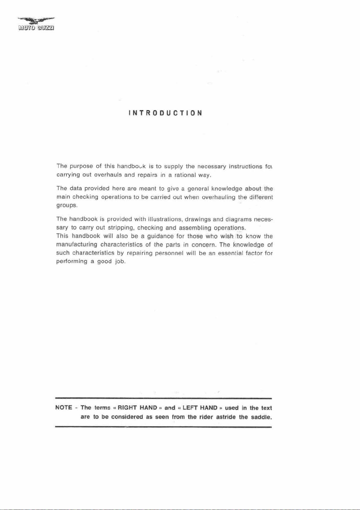
NTROOUCTION
The purpose
carrying
The data provided here are meant to give a general knowledge about the
maln
checking
groups.
The handbook is provided with
sary to
This hand book
manufacturi
such ch
perfo rming a good job.
of
this
handbovk
out overhauls and repairs in a rational way.
operations to
carry
out
stripping,
will also be a
ng
characteristics
aracteristics
by repairing personnel will be
is
to
supply the necessary
be
carried
illustrations, drawings and diagrams neces-
checking
guidance
of the parts in concern. The
out
when overhauling the
and assembling operations.
for
those who wish to
an
essential
instructions
different
know
knowledge
factor
'0\
the
of
for
NOTE · The terms
to
are
be
..
RIGHT HAND
considered as seen from the rider astri
.,
and
((
LEFT HAND " used In
de
the
the
text
saddle.
Pog.
MAIN FEATURES. 5
TOOLS FOR OVERHAULING 9
DESCRIPTION OF ENGINE
REMOVAL OF
FROM
ENGINE OVERHAUL
Stripping
ROCKER BOX COVERS CYLINDER HEADS
...
FRAME .
of
engine
ENGINE-GEARBOX
..
GROUP
10
11
12
12
VALVES - GUIDES - SPRINGS. 16
Stripping 16
Removal of
Inspection
Inspection and overhaul of valve
Valves-valve guides
Inspection and overhaul of valve seats in cy-
linder
Inspection
Inspection
Valves sealing
Assembling
CYLINDERS - PISTONS - PISTON RINGS AND
Oil
Cylinders
Selection of
Pistons
Selection
Piston rings and
Piston rings and scrapers-piston slots height
clearance
Piston ring and oil scrapers clearance .
Fitting of piston
CON - RODS - CRANKSHAFT - MAIN BEARING, 23
Flywheel
Con-rods
Thickness
Diameter
Small end bushing .
Checking
Checking
Fitting
Crankshaft .
Diameter
Diameter
I/O of main bearing, flywheel side .
I/O
of
Flywheel side flange
ring , 29
Seal
Timing side flange
Timing
Timing
Crankcase .
Inspection and overhaul
Wear
SUMMING
MECHANISM PARTS
TIMING DATA 32
Camshaft 32
Diameter
sings
Checks 32
Tappets
Coupling
springs
and
heads 17
of
of
and
overhaul
valves 18
valve
lest.
of
cylinder
valves.
of
coupling
springs.
cylinder
data .
heads on
heads.
guides
cylinders
16
16
16
17
18
18
19
SCRAPERS 20
wear
check
cylinders
of
piston diameter
011
diameter
scrapers 22
20
20
21
22
22
22
pins
side
- MAIN BEARING,
01
big end bearings . 23
of crankshaft pin 23
Timing
22
side
23
24
weights
paraUelism of end axis. 25
up
con-rods on crankshaft . 25
for
engine balancing 24
27
of main journal, flywheel side
of
main journal, timing
side
.
28
28
28
main bearing. timing side
ring
for
flywheel side flange .
cover
cover
seal ring
check
of tappet guides
UP OF DATA PERTAINING TO CRANK
of crankshaft bearings and
on crankcase 32
data of tappets and tappet guides in
complete
c/w
main bearing
of
with main bea-
crankcase.
In
crankcase 30
their
28
']9
29
29
29
29
30
31
hou-
33
I
II
DE
X
crankcase
Push rods
Rockers 34
Coupling data of
Tappet clearance
Valve timing 34
SUMMING
TIMING PARTS
ENGINE LUBRICATION
Description
Oit
Inspection and
Oit
Oit
011
Oit
Oit pressure gauge
ENGINE ASSEMBLING
ENGINE FEEDING 43
Fuel tank 43
Air
Carburetors 44
Standard
Idling
Top speed adjustment and main
Stripping of
Servicing
ENGINE BRAKE TEST
CLUTCH
Removal
Checking
Checking
Checking
Checking
Checking
Clutch assembling operation 50
Clutch
Checking
Checking
Outer body 50
Cage
Inner
Pressure rod 50
Pressure rod cap
Outer body seal ring
Clutch adjustment .
GEAR
Gear
Gear
Gear
Gear
Gear
Check
Gear
Seal rings 55
Ball bearings and
Mainshaft 56
Layshaft
Fitting clearance between
Layshaft gears .
Fitting clearance between bushings and gears
Sliding muff 57
Clutch
UP
pump
cleaner
piping
pressure
breather
cleaner
carburetor
speed
of
of
clutch
pressure plate 50
driven plates 50
intermediate plate 50
s1arting ring gear 50
control
clutch
clutch
c/w
body 50
BOX
box
description
box control
box
stripping
box
box
cover
and overhaul of the gear box
box and
layshafl 56
on layshaft
shaft
rocker
adjustment
OF
DATA PERTAINING TO
checks
solenoid
on
carburetors
adjustment
carburetor
carburetor
clutch
springs
control
operating
balls 50
cover
roller
arms and
. 34
settings
jet
assembly
lever on gearbox 50
bearings
gear
bushings and
splindles
selection
unit
parts 56
Pa
5~
57
u·
33
33
34
37
38
38
38
38
39
40
40
40
40
41
44
45
45
046
46
48
49
49
49
50
50
51
51
51
52
52
52
53
55
55
5&
.55
5~
.50
3
Pog_
Clutch
shelt
Inner
Cush drive Shaft semi-collar 51
Cush drive plate 57
Cush drive spring
Sl
iding
Idle
geer
Gear selector drum
Preselector
Preselector
Gearshllt
Gear selector forks and fork
Assembling
REAR WHEEL DRIV
DescrlpUon _ _
Stripping
Check
sembly
Rear wheel drive box 60
Drive box Ilange 60
Distance shims _ _ 60
Internal toothed sleeve
Bevel
Cage retaIning ring 60
Rear wneel - drive box distance piece 60
Bear
ing housing 60
Adjusllng
Sh
ims
Bevel
Lockring
Lockring
Seal rings _
Drive shalt-bevel pinion sleeve
Dri
ve
Double Joint
M_
Rubber gaiters
8ali
bearings and
Assembling
Assembling rear wheel drive
fork
Contact
teeth
REAR SUSPENSION 65
Stripping
Check and overhaul 65
Flexib le bushings 65
Fitting up on frame
FRONT SUSPENSION AND STEERING 66
Str
ipping
Overhaul
Fork rods 67
Top
bushings _ 67
Bottom
Fork
bottom
Fork
Spnng
Top
plug
Top
plug seals 68
Steering
Steering adjusting
Steering tube _
Assembling fork and steering
STRIPPING OF REAR SWINGtNG FORK
Overhaul
Nuls
and
Support
Seals
8all
bear
Fi
tting
WHEELS AND BRAKES
Front wheet
Rear wheel
Wheels and brakes check
Wheels
Rims
Spokes
Brake
seal ring 51
body 57
57
sleeve 57
57
57
shalt
, with
sector
shall
01
gear box
E _
return spr ing
operating lever _ 57
gear
shalls
57
57
57
58
59
y;
01 rear wheet drive
and overhaul
of
rear wheel drive as-
59
&J
for
gear set 60
washers
gear
distance piece
safety washer
shalt
taper
01
rear wheel drive _ _
check
and adjustment 01 bevel gear
rear wheel coupling
roller
bearings
10
_ _ _ _ _ _
RlH arm of rear
61
61
61
61
61
61
61
61
61
~
61
61
61
62
63
from Irame 65
65
Of
tetescopic front fork and steering
01
tetescoplc front fork and steering 67
bushings
springs 68
covers
housings 68
rubber rings
taper
roller bearings 68
lockrings
60
67
67
68
68
68
on
Irame lug
68
70
of rear fork
locknuts
spindles
ings
up
rear
and taper
lark
roller
bee rings
70
70
70
70
71
71
72
72
72
73
73
7.
linings
7.
7'
Pall_
Brake springs
Brake cam_
Brake pins
Brake drums
Rear wheel central
Hub seals
Tapper
Tapper
AdJusling weshers
Brake cam lever
Front brake cable
Front brake adjustment
Rear
Assembling
Assembling of fronl
Fitting front
Assembling rear wheel hub
Fitting rear
TAPER ROLLER 8EARINGS AND BALL
BEARINGS
FRAME
Check and overhaul
Rear fender and
Center and side stand return springs
Crashbar
Rear brake
Alder and pillion fcotrests
Assemb!ing
ELECTRICAL EQUIPMENT
BATTERY
Features
Inspection and maintenance
Cleaning
Check
Electrolyte
Charge
Common battery faults
GENERATOR
Descr
Operati
Regulator unit
Testing data
Adlustmenl of generator belt tension
Generator faults
STARTER MOTOR
Description _
Operatlcn
Testing data
Slarler
IGNITION SYSTEM
General inlormation
Coil
Distributor
Automatic spark advance device
Contact breaker
Condensor
Distributor
Spark plugs
Ignition timing
Ignition faults
ELECTRIC HORN
Overhaul and repair In
Tesllng
Electric horn
LIGHTING 117
Head light 117
instruments panel 117
Tal! light and stop
Fuses 117
INSTRUMENTS AND CONTROLS 118
Wiring diagram legend 119
LUBRICATION AND GENERAL MAINTENANCE
CHAAT
roller
roller bearings
brake adjustment
01
wheel on fork and drive
conlrol
and smearing
level
ch
eck
iption
on
molar faults
cap
data
body
bearing housings
wheels
wheelan
wheel hub
lark
1001 boxes
lever,
spindle
and
01
terminal blocks
_ _ _
and
rotor
struction
laults
_ 115
light
box
rod
74
7.
7.
74
"
74
"
74
74
75
"
75
75
75
75
76
76
76
n
78
78
78
78
78
78
78
78
79
79
79
79
79
79
79
'"
81
83
83
B3
83
86
87
88
94
9'
95
W
99
103
103
103
10<
10<
105
105
105
105
106
100
113
113
II
117
121
..
•
MAIN FEATURES
ENGINE
Cycle
Number
Cylinder disposition
80"
Stroke
Displacement
Compression ratio
Revs
Output at max engine
Crankcase
Cylinders
Cylinder
Crankshaft
Crankshaft
Connecting rods
Pistons
Va
O.H.V.,
and
Inlet :
- opens 24° before TOC
- c:oses
Exhaust:
- opens
- closes 22"
Rccker
- 0,5 mm. (.0196")
Normal
- inlet
- exhaust 0.2 mm. (.00787")
Carb
Both carb
Carburetor
type
La;brificatlon
Pressure,
Oil strainer in
Ncrmal
Ibs/sq.ln.)
(Controlled by
Electrfcally
Cooling
By ai
Ignition
By battery
5
Initial advance: 10°.
of
cylinders
:
at
max engine speed
speed
heads
supports
lve
gear
push rod operated via the camshaft
gear
driven by the crankshaft.
sa
n
aller
sa
o
alter
after
clearance
rocker
0.1
uratlon
Oell'Orto 5.
lubricating
r.
Cylinder
123
A.
uretors
by
for
clearance
mm. (.OO393
are gravity fed from the tank.
Make:
5.1.
gear
pump
crankcase
relief valve)
controlled
and
with automatic advance Marelll distri
: in
: steel
:
:
BOC
BOC
TOe
valve
(cold
")
(right and
driven by the crankshaft.
.
pressure
oil
pressure gauge.
cylinder
4 strokes
2
..
V~_90
80
70
703.717 cc. (42.93 cu. in.)
mm
mm
.
.
o
(3
.149
(2
.755")
")
9 to 1
6000 r.p.m.
50
HP
SAE
in 1i9ht alloy
light
alloy barrels with hard
chrome
with
valve
of
in suitable housing (as used in
all
steel
alloy
in
liming
2.5
linings
light
allo
y,
specia
seals
construction
anti-friction
F1
Race car
construction
thin
light alloy
:
engine):
lell)
- 3 kgs.lsq. cm. (35.6 _
heads deeply finned.
hemispherical,
l cast iron inserted
material pressed
s)
wall
with AL-TIN
bearings
In
the crankcase
butor
42.
type
Automatic advance:
Ignition
Contact
Spark
Plugs
Ignition
Starter
Marelli
ratchet control. Ring
Exhaust system
Dual exhaust pipes and mufflers.
TRANSMISSION
C:utch
Twin driven plates,
trolled
Gear box
Four speeds,
Cush
Separate case
pedal on the right hand side of the machine.
Engine-gearbox ratio:
Internal
-
-
- Third
- High
Seconda ry
By constant speed
Bevel layshalt gear-wheel ratio;
Overall
FR.f,ME
Duplex cradle, tUbular
7
~uspen
Rear
Telescopic
Telescopic
Wheels: 18x3 spoked steel rims, front and rear.
Wheels: 18x3 spoked steel rims.
Tires
4.
Front
Solo
With
liming
breaker
plug:
point
coil
molar
slarter
by lever on left
drive
gear
Low
gear
Second
gear
gear
gear
Low
gear
Second gear
Third gear
High gear
slon
swinging
00 x 18
front and rear,
tire
pressure
rider
pillion
n.
gap
: Marelli BE 220 D.
spring incorpora
gear
dri
front
front
2So
.
38° full advance .
gap:
0.42.0.48 mm. (.016-.018").
225 in Bosch-Marelll scale
: 0,6 mm. (.023") .
MT
40
H (12 V - .7 HP) with
gear
boiled
on
dry
type. located on the lIywheel. Con-
handlebar
fr
onta
l engagement. Constant mesh gears
bolted
on crankcase, operated by
ratios:
ve at rear wheel
homokinet
ratios:
.
ted .
1 to 1.373 (16-22)
ic
double
or
electromagneti
flywheel.
to 1.933
to 1.
to 0.954
to 0.
l
oint
1
1
1 to 6.066
1 to
struclure.
fork with external adjustable
fork
incorporating
fork with external
block
1,5 kgms/SQ.
hydraulic
front
type
om
adjustable
and rear.
..
high speed
.
eQuivalent.
263
754
cardan
4.625 (8-37)
to
to
springs
.
dampers.
spring
_.
21
P.
S.1.
rocker
(15-29)
(19-24)
(22-21 )
(24-18)
shal
12292
8.031
4]94
.
c
l
5
Rear
tire
Solo
rider
Wilh
pillon
Note
- The above reeommendation is
sing speed).
on
motorway
0.2
kgms/sq
!I
using Ihe maehlne
s !he above pressures should be Increased by
. cm. (2,8 P.S.I.).
1.8 kgmslsq. cm. = 25 P.S.I.
2.0
Bntkes
Twin
lead
ing
shoes
exp
hand
lever on the r
Large
rear brake operated by pedal on
mac
hine
.
Overall
dlmen
t lons and
-
Wheelba~e
-
Lenglh
- W
idth
-
Height
- M
-
(dry)
in
imum ground
Curb
weigh!
anding
ight
handlebar.
weight
clearance
kgms
/sq. cm. =
al
type
28
lor
normal
eonslanl
Ironl
1.445
2.230 mls. (abl. 87.5" )
0.
1.
O.
high
brake. operate
lell
hand
mls
795
miS.
0SO
miS. (abt. 41.2"')
ISO
mets. (abl. 5.
riding
. (ab
(abt.
P.S.!.
(crui·
speed
sioe
t.
56.9
31.2")
243 kgs 536 Lbs
or
d by
of
")
9")
Performance
Maximum permissi
each gear.
L
ew
Seco
ty 34%
Tl>
ird gear 120 kms/ h (74.5 m.p.h.)
ty
'<:3
High
Capacities
Fuel tank:
solo riding.
gear
nd gear 96
'/0
gear
20
reserve (about 1 USA gl) - Petrol
Sump 3
mission 0.750 liters
wheel drive 0.300
Front
1I1ers
lor
k dampers 0.160
ble
speed and
66
Kms/h
(41
kms/h
m.p.h.) Clmblng ability
(59.6 m.p.h.) Cli
170 kms/h (106 m.p.h.)
liters
(5.28 US gla.)
(3'1. Quarts) Shen
(1
~/.
liters
(5/8 Pints) Shell Splrax 90 E. P. -
98
/100
Pln!s) Shell Spirex 90
Multigrade
liters = 5,4
lux 33 -.
gradients
Climbing
inc
lud
ing
No
Climbing
(Regular
climbab
mbing
ability 14l/a
aboul 4 liters
20/40 _ Trans-
E.
P. - Rear
oz USA ~ Shell Tel-
le
in
60%
abili-
abil
oclane)
i-
6
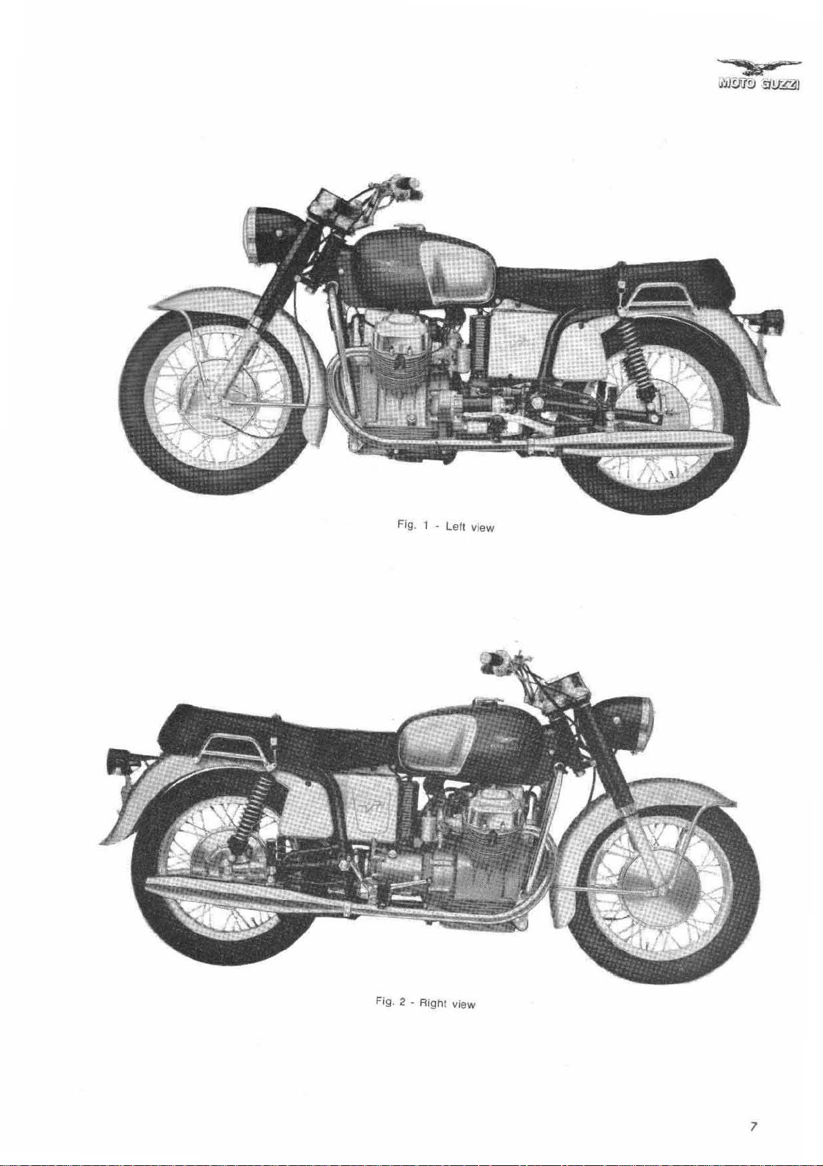
Fig. 1 -
lelt
view
Fig. 2
- RighI view
7

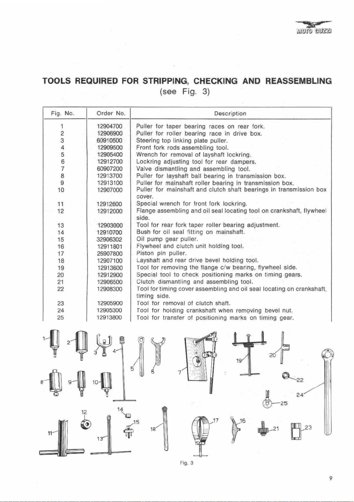
TOOLS REQUIRED
FOR
STRIPPING, CHECKING AND REASSEMBLING
Fig . No .
1 12904700
2 12906900
3 60910500
4 12909500
5
6
7
8
9 12913100
10 12907000
11
12
13 12903000
14
15
16
17 26907800
18 12907100
19 12913600
20 12912900
21
22 12908300
23
24 12905300
25 12913600
Order
12905400
12912700
60907200
12913700
12912600
12912000
12910700
32906302
12911801
12906500
12905900
No.
(see Fig.
Puller
Puller
Steering top linking plate puller.
Front fork rods assembling tool.
Wrench
L
Valve
Puller
Puller for mainshaft roller bearing in transmission box.
Puller for mainshaft and clutch shaft bearings in transmission
cover.
Special
Flange assembling and oil seal locating tool on crankshaft, flywheel
side.
Tool
Bush
Oil
Flywheel
Piston pin
layshaft
Tool
Special tool
Clutch
Tool
timing
Tool
Tool
Tool
for
for
ockring
dismantling
for
for
for
pump
for
for
side.
for
for
for
taper
bearing races on rear
roller
bearing race in
for
removal of Jayshaft
adjusting tool for rear dampers.
layshaft ball bearing in transmission
wrench
resr
oil seal
gear
and
and
removing the
dismantling
timing
removal of
holding
transfer
fork
clut
puller
rear
to
cover
for
puller
check
3)
Description
drive
lockring
and assembling tool.
front fork
taper
fitting
.
ch
unit
.
drive
flange
positioning
and
assembling and oil seal
clutch
crankshaft
of pOSitioning marks
lockring.
roller
bearing adjustment.
on
mainshaft.
holding
bevel
assembling
tool.
holding
c/w
bearing.
marks
shaft.
when removing bevel nut.
fork
box.
.
tool.
flywheel side.
on
tool.
on
.
box
timing
locating
timing
.
gears.
on crankshaft.
gear
.
box
1-IJ
8~
2~
9~
3~4
10~
12
@
.
~
19
5
14
~
~15
1
Y
6
18
7
Fig. 3
17
~'6
~+
~22
24
~
.21
25
rJ23
~
l'
I
9

DESCRIPTION OF ENGINE
..
(see Fig. 4 &
The"
V7»
model is
der 90' V engine.
rels
with
hard
finned
Cylinder
for
cooling
bottoms fit into
equipped
Cylinders
crame
.
lining
5)
with a
have
s and are deeply
suitab
light
le
housings
twin-cylin-
alloy
crankcase.
Crankcase
(four long,
cylinder
Cylinder
cast iron inserted valve seats.
Rocker
tion
crankshaft
main bearings, pressed in suitable housings.
Steel
ings
ends.
Piston in
piston
pin
(oil scraper),
O.H.V. valve gear,
tappets, push rods and rockers. Camshaft
driven
Pressure
in
ligllt
alloy ,
two
short)
heads.
heads are in
box
covers
construction
at big
ends
light
rings
and
by
crankshaft. Carburetors
lubrication
in
light
on
two
special
con-rods
and bronze bush es at small
alloy. with 4 rings: 3
one
oil
operated
from oil sump
provided
to
secure
light
alloy. Steel
scraper)
with
cylinders
alloy, with special
tin-aluminium
with thin
over
through camshaft,
are
six
construc-
wall
pin (t
and 1
gravity
through
bolts
alloy
bear-
belo
gear
gear
bar-
in
and
wo
w
fed.
.:.
,
'\'(r~'
";'~
:Y·!~
-
.
'.
..
'
,',
,
..
,
~
.. ' ..
,
'j:
••••••
~~
..
~
....
~
, \. '".
""':
'.
pump
driven by crankshaft. Oit recovery by
vity. Wire gauze
Lubrication
Breather
box
from which,
into
sump.
Pressure
tube
. Engine is
heads are
Ignition by battery ,
by
crankshaft
ctric
Ele
pressure control
tube
conveys
is discharged
air
suitably
through
starting,
Fig. "
type
oil
cleaner
led by relief valve .
oil
vapors Into
after
condensation.
outside
cooled. Cylinders
finned .
coil
and
distributor
built-in
electrically
gear
controlled.
in
crankcase
breather
oil
returns
through
and
cylinder
operated
.
gra-
.
vent
10
Fig. 5
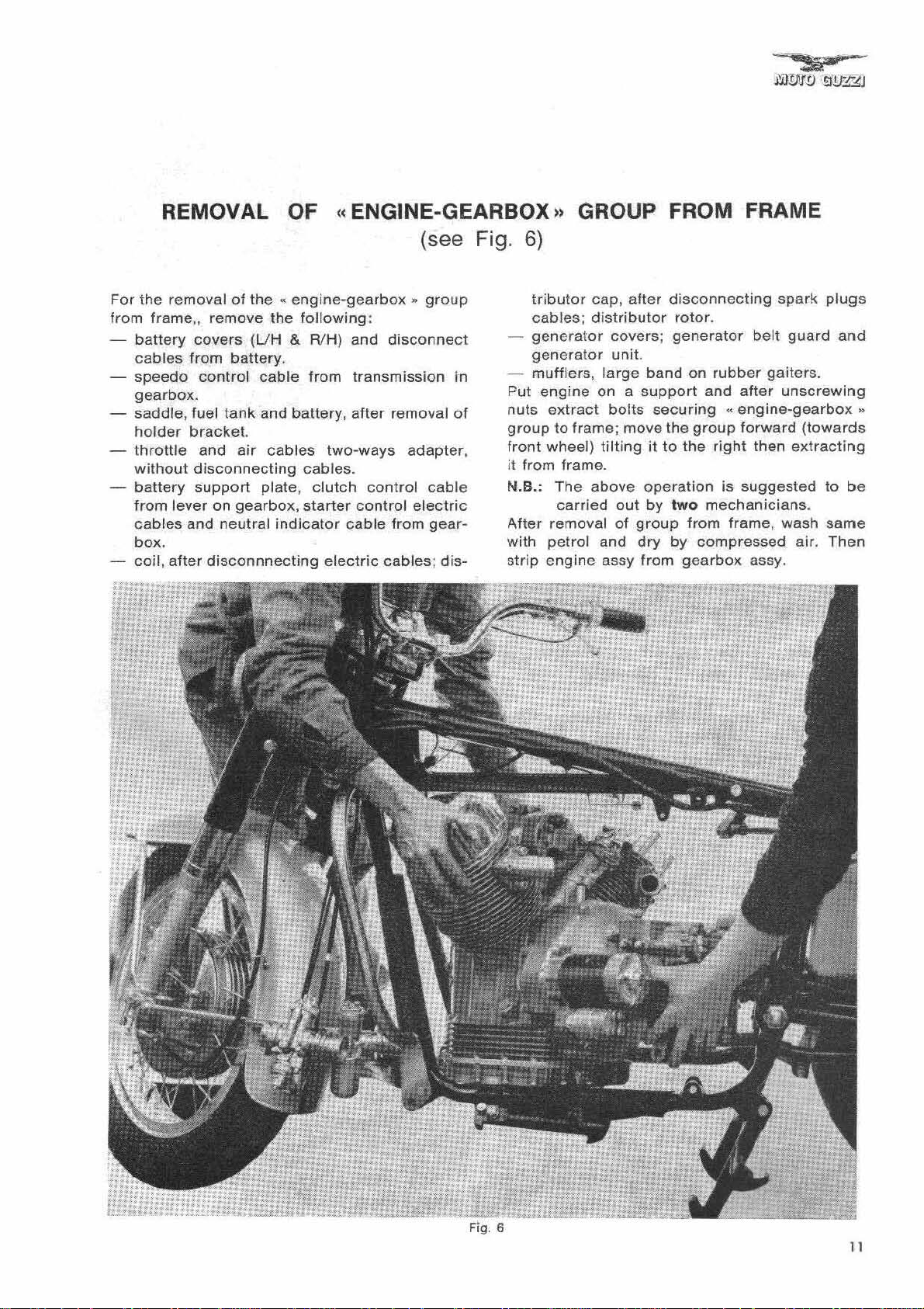
REMOVAL OF " ENGINE·GEARBOX» GROUP FROM FRAME
For
the
removal of the
from
frame"
battery
cab
les from
speedo
gearbox.
saddle, fuel
remove the
covers (UH & RlH)
battery
control
tank
holder bracket.
throttle
without
battery
from lever on gearbox,
cables and neutral
box.
coil, after
and
air
disconnecting
support
disconnnecting
(see Fig.
..
engine·gearbox,.
following:
and
.
cable
and battery , after removal
plate,
from
transmission
cables two-ways adapter,
cables.
clutch
starter
indicator
control
control
cable
electric
group
disconne
cable
electric
from gear-
cables;
dis-
ct
in
of
6)
tributor
cables;
generator
generator
mufflers,
Put
engine
nuts
group
front wheel)
it
from frame .
N.B.: The
After removal
with petrol and dry by compressed air.
strip
cap, after
distributor
covers;
unit.
large
band
on a
support
extract
to frame; move the
carried
engine
bolts
securing
tilting
above
it to
operation
out by two mechanicians.
of
group
assy from
disconnecting
rotor.
generator
on
rubber
and
«engine·gearbox»
group
the
right
is suggested
from frame, wash same
gearbox
spark
belt
gaiters.
after
unscrewing
forward
then
assy.
guard
(towards
extracting
plugs
and
to
be
Then
11
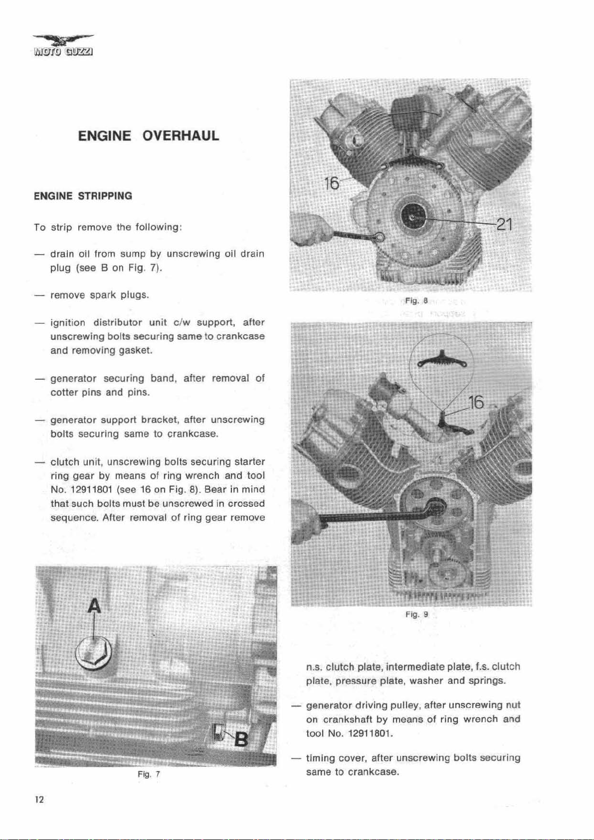
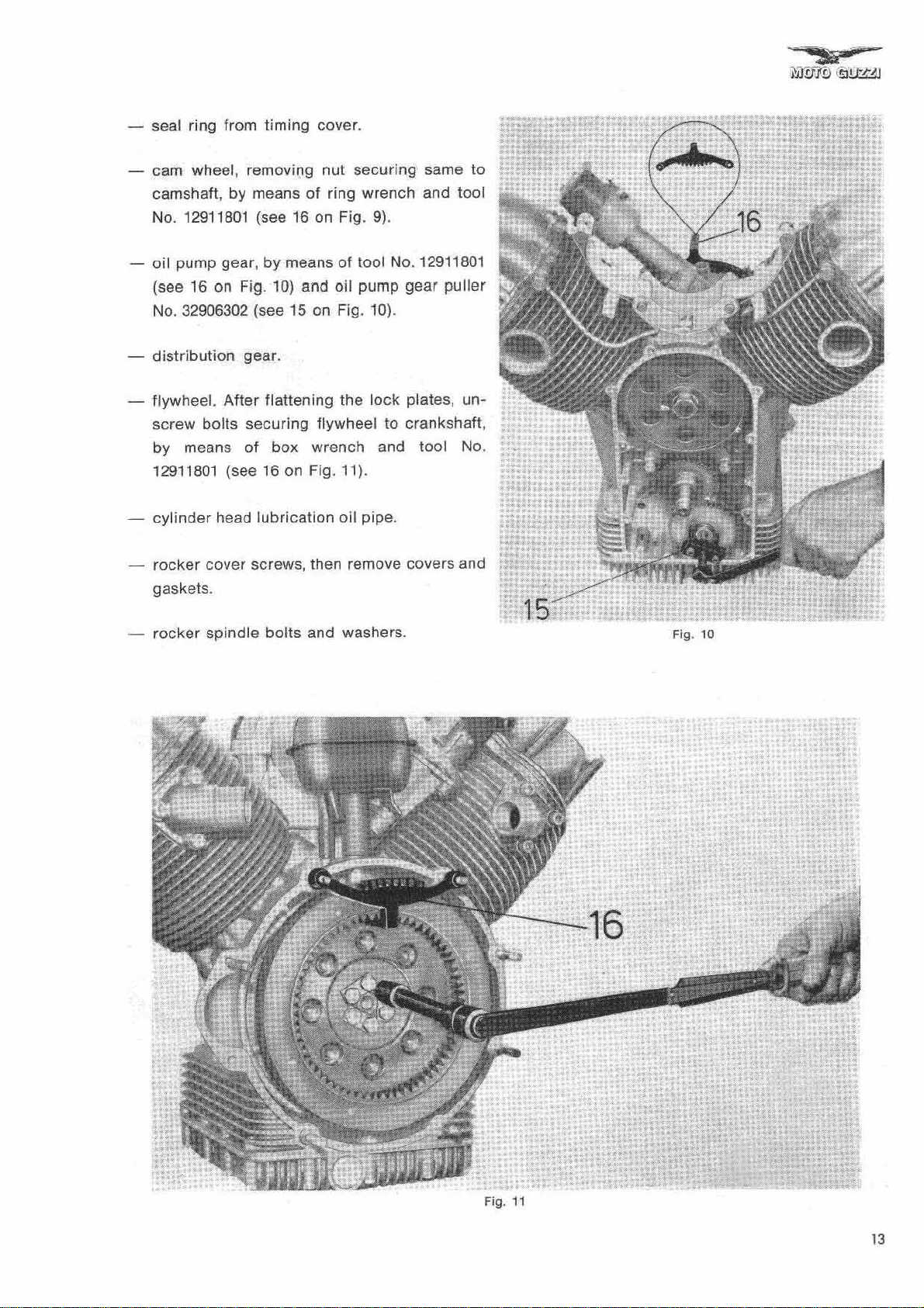
ENGINE OVERHAUL
ENGINE STRIPPING
To
strip remove the following:
drain oil from sump
plug (see B on Fig. 7).
remove spark plugs.
ignition
unscrewing bolts securing same to crankcase
and removing gasket.
generator
cotter pins and pins .
generator
bolts securing same to crankcase.
clutch
ring gear by means of ring wrench and tool
No. 12911801 (see 16 on Fig. 8).
that such bolts must be unscrewed in crossed
sequence. After removal of ring
distributor
secur ing band,
support
unit
, unscrewing bolts securing starter
by
unscrewing
unit c/w support,
after
removal
bracket, after
unscrewing
Bear
gear
oil
drain
after
in mind
remove
01
Fig. a
12
Jj
..
Fig
. 7
n.
S.
clutch plate, intermediate plate,
plate , pressure plate, washer and
generator
on crankshaft by means of ring wrench and
tool No. 12911801.
timing
same
driving
cover,
to
crankcase.
pulley,
after
after
unscrewing bolts securing
1.5.
springs
unscrewing
clutch
.
nut
seal ring from
cam
wheel , removing nut securing same to
camshaft, by means
No. 12911801 (see 16 on Fig.
timing
cover.
of
ring wrench and tool
9)
.
oil pump
(see
No. 32906302 (see
distribution
flywheel.
screw
by means of
gear
, by means of
16
on Fig. 10) and
15
gear.
After
flattening the
bolts securing flywheel to crankshaft ,
box
12911801 (see 16 on Fig. 11).
cylinder
rocker
gaskets.
-
rocker
head
lubrication
cover screws, then remove covers and :;
spindle
bolts and washers.
1001
No. 12911801
oil
pump
on Fig. 10).
wrench and tool No.
oil
lock
pipe.
gear
puller
plates , un-
"
Fig.
10
--16
Fig.
11
..
13
rocker
springs
arm spindles,
rocker
and washers (see Fig. 12). Remove
tappet adjusting screws
push rods.
arms,
after
loosening nuts.
rocker
arm
rocker
long
which
crankcase
cylinder
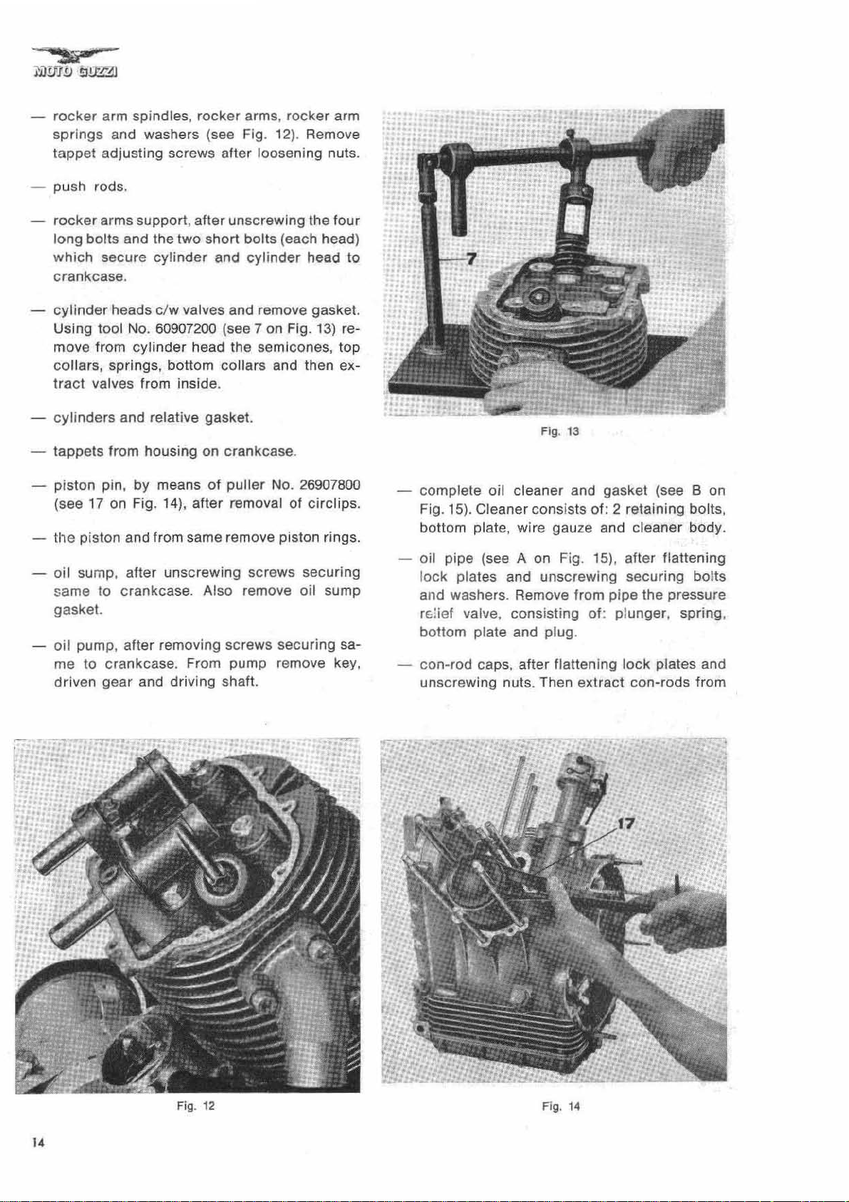
Using tool No. 60907200 (see 7 on Fig.
move from
arms support,
bolts and the two
secure
after
cylinder
unscrewing the
short
bolts (each head)
and
cylinder
.
heads c/w valves and remove gasket.
cylinder
head the semlcones,
head
13)
four
to
re-
top
collars, springs, bottom collars and then extract
valves from inside.
cylinders
tappets
piston pin, by means
(see
the
oil
same to
and relative gasket.
from housing on
17 on Fig. 14),
crankcase
of
puller
after
No. 26907800
removal of circlips.
.
piston and from same remove piston rings.
sump ,
after
unscrewing screws securing
crankcase
. Also remove
oil
sump
gasket.
oil
pump,
after
removing screws securing same to crankcase. From pump remove key,
driven
gear
and driving shaft.
Fig.
13
co mplete oil cleaner and
15)
Fig.
. Cleaner cons ists of: 2 retaining bolts,
gasket
(see B on
bottom plate, wire gauze and cleaner body .
oil pipe (see A on Fig. 15), after flattening
lo
ck
plates and
unscrewing
securing bolts
and washers . Remove from pipe the pressure
r
",!
ief valve , cons isting of: pl
ott
om
b
con-rod
plate and plug .
caps,
after
flattening
unger, spring
lock
plates and
unscrewing nuts. Then extract con- rods from
,
Fig.
12
Fig. 14

top
of crankcase. Remove
con-rods.
camshaft,
flange
after
to
crankcase.
half
bearings from
unscrewing bolts securing
flange c/w
after
flatten ing lock
bo
lts securing flange to crankcase.
crankshaft
bushing,
plates and
timing
unscrewing
flange c/w main bearing, flywheel side, after
flattening
securing flange
of
tool No. 12913600 (see 19 on Fig.
ve
flange c/w main bearing from crankcase .
lock
plates and unscrewing bolts
to
crankcase. Then, by means
16)
crankshaft.
oil
pressure solenoid .
oi l
filler
plug
(see A on Fig. 7).
After the above operations the crankcase is
pletely stripped,
except
for
the
long and
bolts.
N.B.:
During
ed
rod-piston
stripping
to
keep well apart
..
groups.
it
is
strong ly recommend-
the
two
..
cylinder-
side,
remo -
Fig. 15
com-
short
To remove timing cover
from frame,
- after removing
unscrew
sembly. Extra ct
it is necessary to proceed as
belt
the
three bolts securing pulley as-
pulley
without
cover and
removing engine
generator
outer
flange and
washers.
using the three bolts previously securing pulley, fit tool No. 12905300 on
24
on Fig. 17) and thus
unscrew crankshaft nut
pulley hub (see
holding
by
crankshaft
means
of
wrench.
unscrew
tool,
block
the
inner
or
support
three
body
bolts
and remove special
of
pulley and pulley
engine.
remove bottom frame/engine stud.
rem ove screws securing
timing
cover
crankcase.
follows
belt.
a ring
hub
.
Ie
:
16
Fig.
,
Fig.
17
15
ROCKER BOX COVERS - CYLINDER
HEADS - VALVES - GUIDES
- SPRINGS
Cylinder
se
nuts secure
STRIPPING
Removal and stripping of
quired
loss being imputable
and also
order
c
hamber.
When engine is on frame,
ping
Disconnect:
- sparks cables.
-
- exhaust pipes and muffler
-
-
-
Then remove cylinder head
No
linde
overhaulfng and assembling operations, and re·
quired
graphs:
heads, in light alloy, are finned to increa-
coo
ling surface. Long bolts, short bolts and
cylinder
when loss of compression
after
to remove carbon deposits in combustion
Is
carried
air
inlet tubes and
distributor
rocker
rocker
difficulties
r heads
tools, are lIsted in the
Qut
cap .
box
arms and
are involved
into
heads to crankcase.
cylinder
to
defective valve sealing,
a certain period
cylinder
as follows:
carburetors
s.
covers.
rocker
parts.
arms supports.
s.
in
strippi
In
any case all stripping,
heads are re-
is
noticed, such
of
operation, in
heads strip-
.
ng
down
following
cy·
para·
Fig.
18
REMOVAL OF SPRINGS AND VALVES
PositIon
7 on Fig.
the
co
linder
INSPECTION AND OVERHAUL
OF CYLINDER HEADS
Using a chamfered
move
INSPECTION AND OVERHAUL
OF
Valve
cylinder
ried
& 19). Valve
excessive lash between its hole and the valve
stem, whenever such lash
simply
After
reamed
same
Negative
housings
exhaust valves. is
mm.
cylinder
13)
valve top co llar so to remove semicones,
llar
, spring, bottom plate and, from inside
head,
carbon
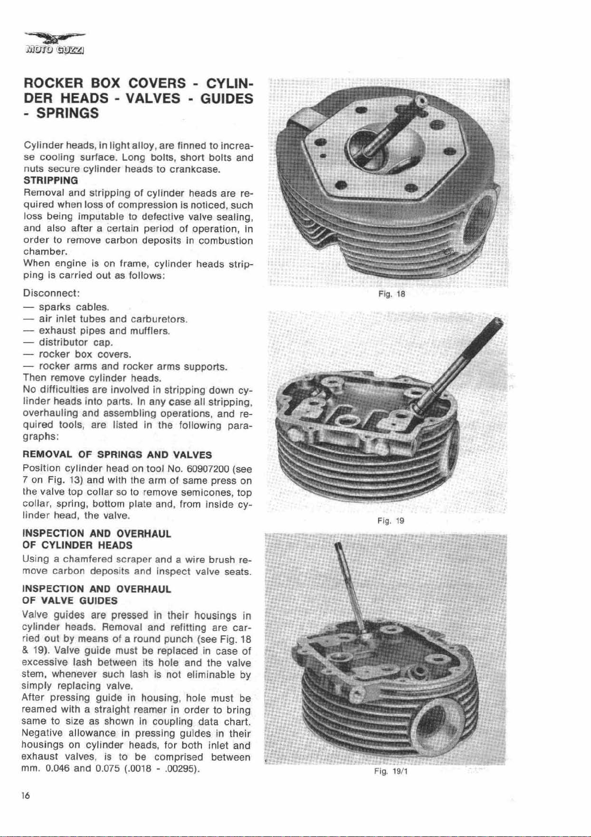
VALVE GUIDES
guides
heads. Removal and refitting
out
by means
replacing valve.
pressing
wit
h a
to
size as shown
allowance
on
0.046 and 0.075 (.0018 - .(0295).
head on tool No. 60907200 (see
and with the arm of same press on
the
valve.
scraper
deposits
are pressed in
of
a round punch (see Fig. 18
guide
cylinder
must be replaced in case
guide
straight
in
to
and a wire brush re-
and Inspect valve seats.
their
housings in
are
is
not
eliminable
in housing , hole must be
reamer in
In
coupl ing
pressing
heads,
be
order
data
guides
for
both inlet and
comprised
to bring
in their
between
top
cy-
car-
of
by
chart.
•
f
r
fi
•
Fig.
19
t
Fig. 1
9/
1
16
Inlel
va lve
Exhaust valve
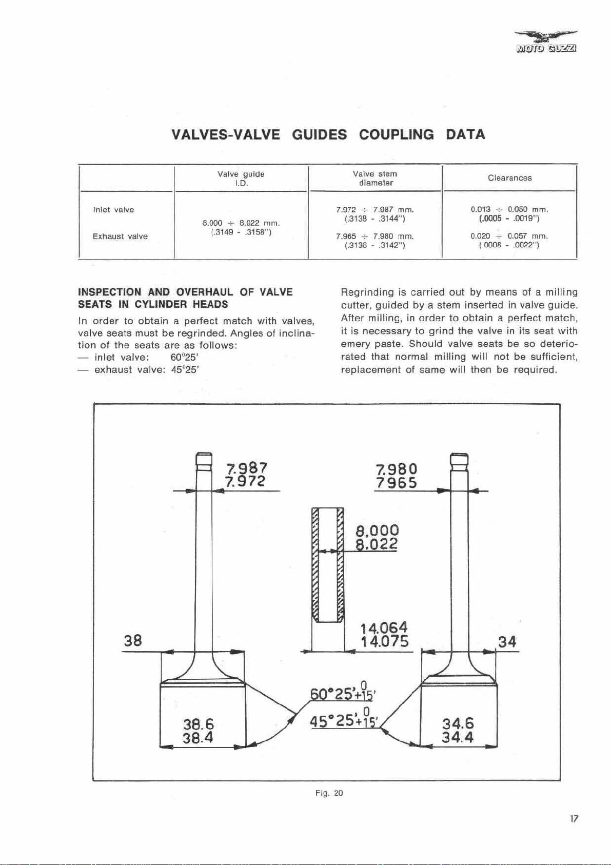
VALVES-VALVE GUIDES COUPLING DATA
Valve
guide
I.D.
8.000 + 8.022 mm.
{.3149 - .3158"}
Valve slem
di
ameter
7.987
7.980
rnm.
mm.
7.972
+
(.3138 - .3144") (.0005 - .0019")
7.965
-+
(.3136 - .3142") (.0008 - .0022
0.013
0.020
Clearances
-+
0.050
~
0.057 mm.
mm
")
.
INSPECTION AND OVERHAUL OF VALVE
SEATS IN CYLINDER HEADS
In
order
valve seats must be regrinded. Angles of
tion of the seats are as follows:
- exhaust valve: 45°
to
obtain a perfect
inlet valve:
60025
25'
match
'
with
valves,
inclina-
7.987
7.
972
Regrinding is
cutter,
After
it
emery paste .
guided
milling, in
is necessary to
rated that normal milling will not
replacement of same will then be required.
carried
by a stem inserted
Should
out
by
order
to
obtain a perfect
grind
the valve
valve seats be so
means of a
in
valve
in
its seat
be
milling
guide
match
deterio-
sufficient ,
7.980
7965
8.
000
.022
.
,
with
38
38
.6
38.4
Fig. 20
14.064
14.075
34
34.6
34.4
17

INSPECTION OF VALVES
Check
stem
data
valve stem
Grinder
table
tion as
- exhaust valve:
valves
and
guide
chart
(see Fig.
so
that valve
follows:
integrity
(for
and
Fig.
20)
In
self-centering
21)
will
4Se 25
and
clearance
. To
and
have an
existing
regrind
chuck
adjust
' +
1~'
lash between
refer
to
coupling
valves, insert
of
Universal
chuck
angle
of
swivel
inclina-
Whenever
to
check
ween 37 mm. and
by
adopting
between spring and cylinder head .
INSPECTION OF VALVE SPRINGS
Check
have
Spring, compressed at
show a load
regrinding
that valve
that valve
not
lost
valve seats, it is advisable
springs
38
mm . (1.456 - 1.496").
suitable
springs
their
elasticity.
of
Kg. 33 + 2 (72 Ibs - 12 ozsl
are
compressed
washers at
are
not cracked
37
mm. (1.456"), must
o
bottom
bet-
Adjust
collar
and
,
-
inlet
valve :
After
grinding
max. dia. to be
Sho
uld surface at stem end
mation.
regrind
SO
check
not
same on
Fig. 22).
U
25
'
thickness
Jess
o
+ 15'
of
valve head at
than 0.8 mm. (.0315") .
show
grinding
any defor-
wheel (see
(closed
Spring, compressed at
show a load
(open valve position).
Springs
apparatus (see Fig. 23). As to load and
tion data refer to Fig. 24.
VALVE SEALING TEST
After reassembling valves
up
if
any, will
bustion
valve position).
flexibility
inlet
and exhaust
be
chamber.
of
Kg.
can
ducts
detected
28
mm. (1.024"), must
o
60
+ 2 (132 Ibs - 4 ozs)
be
checked
on
cylinder
with gasoline. Losse
by
liquid
by
leaking
suitable
deforma-
head, fill
s.
in
com-
18
Fi
g.
23
J
.-J
~
:.J
.aooo
48.010
37
2t
Kq
33
Kg60.g
j (
r
(
r
(
•
Fig. 24
ASSEMBLING OF CYLINDER HEADS
ON
CYLINDERS
Assembling of
ried
out
- reposition a
and
cylinder
tion openings in gasket match with
holes
-
secure
crankcase.
-
fit
rocker
- position
-
screw down
crossed sequence , without tightening. Using
a
torque
ft.lb)
nuts
Fig.
25
cylinder
as
follows
in
cylinder
the head assembly
arms
washer
nuts
wrench
gradually
accordingly
(1-2-3-4-5-6).
heads on
:
new
gasket
head,
making
and
cylinder
support.
on
cylinder
on
long
rated at Kg/m. 3.800 (27.48
tighten
to
cylinders
between
sure that
head.
to
the
bolts
and
short
long
and
sequence
lubrication
six
.
cylinder
bolts
short
shown
is car-
lubrica-
bolts
, in
bolt
in
in
punch
by
-
fit
rocker
-
fit
head in
connect
-
- insert
head.
-
fit
-
fit
fit
-
-
connect
Repeat same assembling
cylinder
insert
bolt
a new gasket
rocker
inlet
air
inlet
air
inlet
distributor
head.
spindle
and washer.
box
cover
box
cover
crossed
cylinder
tube
tube
tube
cap.
sparks
between
.
sequence
head
reducing
seal.
complete
cable.
and secure it to
cylinder
and
screw
lubricating
operations
.
bush on
with
carburetor
it
to
for
support
head
cylinder
pipe
.
cylinder
second
and
.
N.B
.:
In
heads
ti
positioned, fit
Iy
c/w
After
order
to
avoid
during
ons
must be
adjusting
having lined them all up,
screw
deformation
assembling, above
strictly
on
followed
support
, spring and washer.
of
.
the
rocker
by
means of a
cylinder
instruc-
arms
Fi
g.
25
19
CYLINDERS - PISTONS - PISTON RINGS
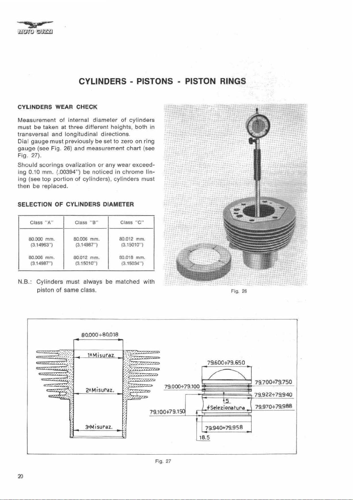
CYLINDERS WEAR CHECK
Measurement
must
be
transversal and longitudinal directions.
Dial gauge must previously be set to zero on ring
gauge
Fig. 27).
Should sea rings ovalization
ing 0
ing (see
then be replaced.
SELECTION OF CYLINDERS DIAMETER
N.B.: Cylinders must always
(see Fig.
.1
0
Class "A"
80.000
(3.14963")
80.006
(3.1
4987")
piston of same class.
of
internal
taken at three
26)
and measurement
mm
. (.00394") be noticed in chrome lin-
top
portion
rnm
. 80.006 mm.
mm
.
60.01
diameter
different
or
of
cylinders) ,
Class
"8"
(3.14987") (3.15010
2
mm
(3.15010
. 80.018
")
of
cylinders
heights, both in
chart
any wear exceed-
cylinders
Class "
80.012 mm.
(3.15034 " )
be
matched with
C"
")
mm
(see
must
.
•
• h:'
..
.'#
.
'.,
• •
•
..
"
.
:
.
...
•
. .
,
..
"
.
..
.
.
..
...
.
Fig. 26
'"
20
eo.OOO+80
3tMisuraz.
.018
Fig.
27

PISTONS
When overhauling, decarbonize piston crowns
and
ring slots. Then
ance (see Fig. 28).
If clearance exceeds measurement stated by
chart, then replace cylinders and pistons.
For engine balancing, both pistons must be of
some
ference is 1.5 grammes
Selection
must be taken at 18.5 mm. (.7283")
bottom
to piston
have to be 0.055 :- 0.065 mm.
less than selection size.
weight.
As
to sizes refer to chart
measurements
edge, In
pin
axis
check
Maximum
orthogonal
(see Fig. 30) Qvalization shall
cylinder-piston
permissible
(23
grains) (see Fig.
on
Fig.
31.
shown
in
sense with
(.OO21
weight
chart
from
-;-.
clear-
dif
29)
below
piston
respect
.0025")
-
.
Fig.
29
Fig. 28
1.990
..JL
1.978
03+045
0.25'0.40
2.
490
2.478
22.00'
Q3"'0.45
rCJ:::::::J
0~.40
3.990
3.978
Fig.
31
18.5
/
~
Sele
Fig. 30
'"
,
ianatur
i~~70
7
.952
..
"
SELECTION OF PISTON DIAMETER
Class
"A"
79
.952 mm.
(3.14nq
79.958
mm
. 79.964 mm.
(3.14798
N.B.: Pistons must always be matched with cy-
")
linders of same class.
Class "B" Class "
79.958 mm. 79.964 mm.
(3
.14798'·) (3.14821")
79.970
(3.14821'·) (3.14845"\
C"
mm
'
.
-::t:::::::!:m:~:·.m:.!!.
,
............
!!
..
··t·,·
;;:.:.:t:;:::,;w::;:·
_
.:·_······
::.:.::
....
• 1"'" : ;
. .:::*'
..
. -
-
:
...•.........
...
r.··· · ..
·····1
.•
·:1:···
::;:::
.. : ..
:::
..
..
. .
...
..
:.
-:.
:
•
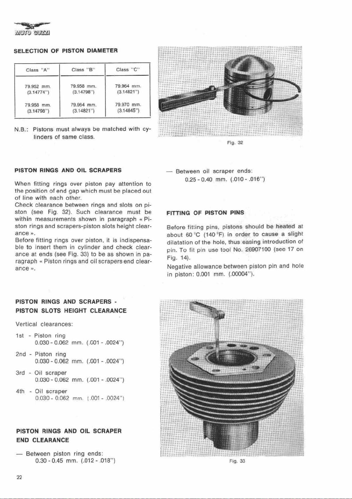
Fig.
..
32
PISTON RINGS ANO OIL SCRAPERS
When fitting rings over piston pay attention
the position
of
line with each other.
Check clearance between rings and slots on piston (see Fig. 32). Such clearance must be
within
ston rings and scrapers-piston slots height clearance
".
Before fitting rings over piston,
ble
to
ance
at ends (see Fig.
ragraph
ance
".
PISTON RINGS AND SCRAPERS -
PISTON SLOTS HEIGHT CLEARANCE
Vertical clearances :
1 st -
of
end gap which must be placed
measurements shown in paragraph
it
is indispensa-
insert them in
..
Piston rings and oil scrapers end clear-
Piston ring
0.030 - 0.062
cylinder
33)
to be as shown in pa-
mm
. (.001 - .0024")
and check
to
out
..
Pi-
clear-
Between oil scraper ends:
0.25 - 0.40
FITTING
Before
about
dilatation
pin. To
Fig. 14
Negative allowance between piston pin and hole
in piston:
OF
fitling
60 °c (140 t
of
fil
pin use tool No. 26907100 (see
).
0.001
mm
. (.010 - .016
PISTON PI
pins
, pistons should be heated at
the
hole
mm. (.00004").
NS
F)
in
order
. thus easing
")
to
cause a slight
introduction
17
of
on
2nd - Piston ring
0.030 - 0.062
3rd Oil
4th Oil
PISTON RINGS AND OIL SCRAPER
END CLEARANCE
Between piston ring ends:
22
scraper
0.030 - 0.
scraper
0.030 - 0.062
0.30 - 0.45
mm
062
mm.
mm
mm
. (.012 - .018")
. (.001 - .0024")
(.001
- .0024
. I .
001
- .0024" I
")
,
H.l'l
Fig. 33
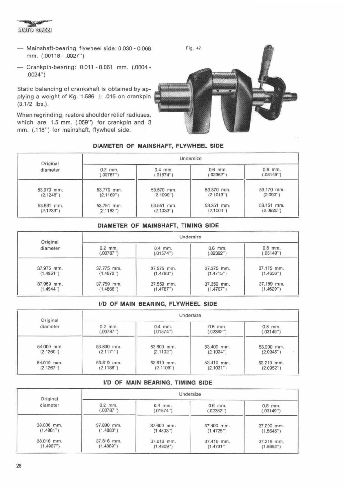
CON-RODS
CRANKSHAFT MAIN BEARING, Flywheel side
MAIN BEARING, Timing side
CON-RODS,
When overhauling con-rods. check the following:
-
conditions
ance
- weight
parallelism
big
end bearings.
Big end
of
small end
bushings
and_ c
between same and piston pins.
of
both con-rods.
of
the
two
axis.
bearings
are of
thin
wall
type, in
lear-
antifric-
tion alloy, and do not allow for any adjustment.
Therefore
are
place. When
must be
shaft pin, measure
wear
of
o/s
if
scoring,
detected,
replacing
reconditioned.
point
(see Fig. 44) in
replacement
positive
diameter
bearing
excessive
replacement
bearings,
Before
of same at
order
and
wear
or
seizing
must
crankshaft
regrinding
to
select
consequently
take
pin
crank-
major
class
to
which
diameter
reground.
bearings»
crankshaft
Refer
to
and
"Diameter of
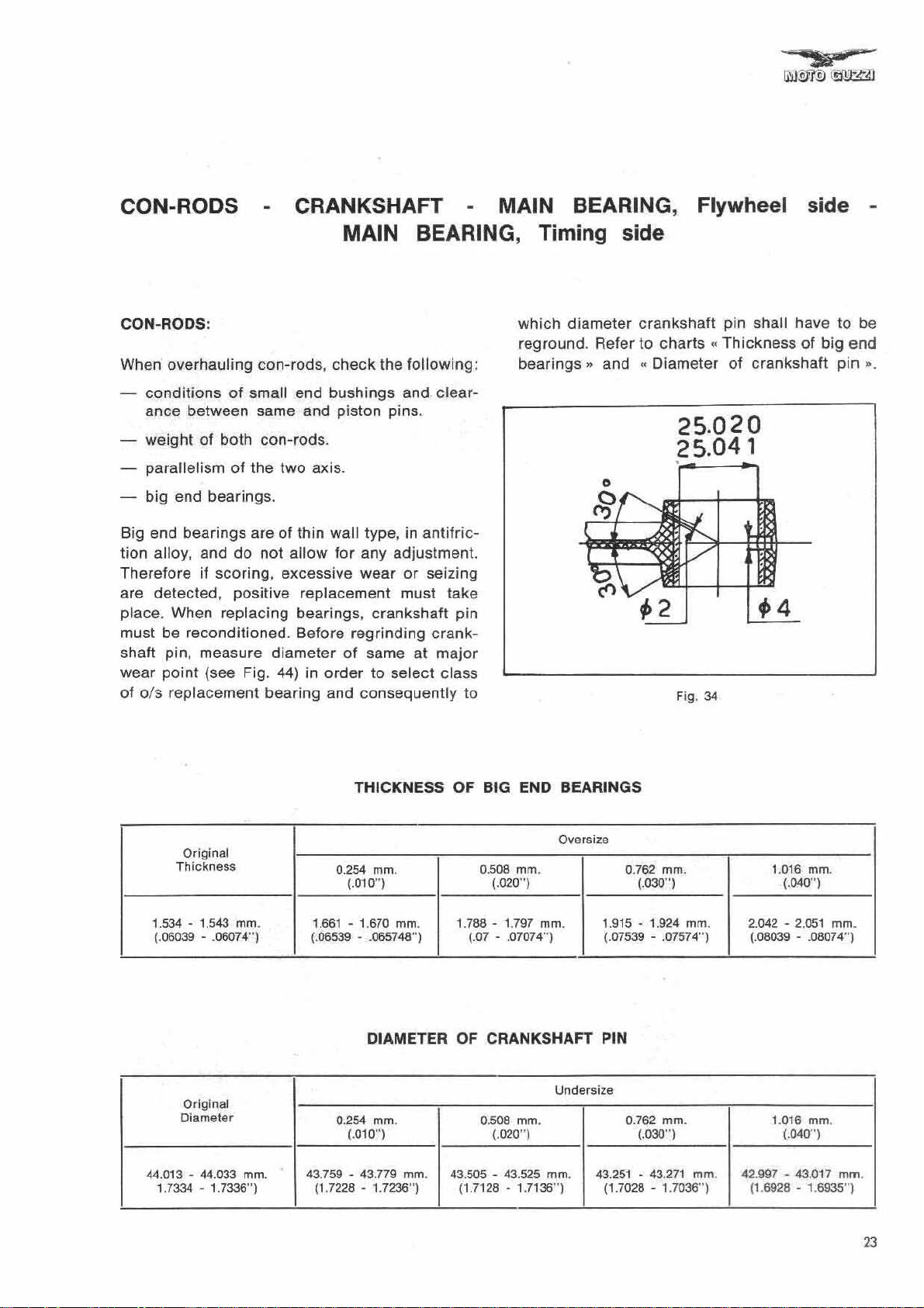
charts
..
25.020
5.041
Fig.
34
pin shall have to be
Thickness
crankshaft
of
big
end
pin
D.
Original
Thickness
1.534 - 1.543 mm.
(.06039 - .06074"')
Original
Diameter
44.013 - 44.033 mm.
1.7334 - 1.7336
"')
THICKNESS OF BIG END BEARINGS
Oversize
0.254 mm.
(.010"') (.020") (.030")
1.661
- 1.670 mm. 1.788 - 1
(.
06539 - .065748"')
DIAMETER
0.254 mm. 0.508 mm. 0.762 mm.
(.010")
43
.759 - 43.779 mm. 43.505 - 43.525 mm .
(1.7226 - 1.7236
"')
0.508 mm . 0.762 mm .
.797
(.07
OF
CRANKSHAFT PIN
(.
(1.7126 - 1.7136
mm.
- .07074") (.07539 - .07574"')
Undersize
020
")
")
1.915 - 1.
43.251
(1.7028 - 1.7036" )
924
(.030")
-43.
271
mm.
mm.
1.
016
mm.
(.040"')
2.042 -
42
2.051
(.08039 - .08074"')
1.016 mm.
(.040"')
.997 - 43.017 mm .
(1.6926
- 1.6935")
mm.
23
SMALL
END BUSHING
Bushing
surfa
is
pressed in con
ce
must not show any seizing mark,
-fod
and
scoring or excessive wear. II so, it
placed. Deteriorat
from con-rod
After
new
bushing
be
drilled
in
in con-rod (see
then be reamed
in
following
I/O
01
after pressing-In
22.020 -22.041
0.014 - 0.040
bushing
and reaming
(.8669 - .8678 ") (.8662 - .8663" )
Pin-bushing
clearance
(.0005 - .0015")
ed
bushing must be removed
by
means of suitable round punch.
Is pressed-In, the
correspondence
Fig. 30).
to
bring
chart
(see Fig. 35).
mm
.
mrn
.
with
Inside of bushing must
dia
meter to sizes shown
Piston pin
22.001 - 22.006
its internal
must
same
holes
existing
dis.
mm
deep
be
must
.
re-
Weigh t
grams
of
complete
(1
Ib 33/ 4 ozs).
Fig. 36
con-rod
as
above:
560 +
~O
CHECKING WEIGHT FOR ENGINE BALANCING
Con-rods,
bolts
and
complete
lock
plate
with
sma ll end bushing, nut,
s,
must be
of
same weight.
Maximum
perm
issible
grains) (see Fig. 36) .
difference
: 3
grams
(46
Fig. 35
Fig. 37
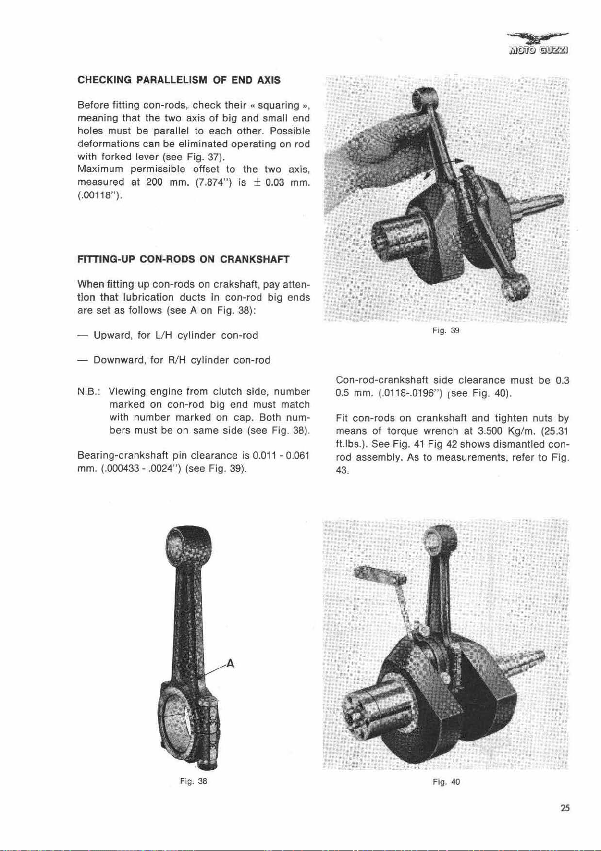
CHECKING PARALLELISM OF END AXIS
Before fitting
meaning
holes
deformations
wit
Maximum
measured
(.00118").
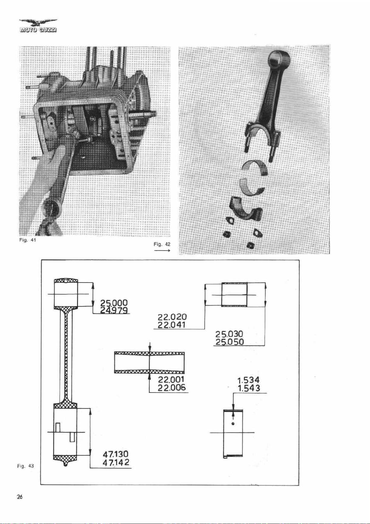
FITTING-UP CON-RODS ON CRANKSHAFT
When
tion
are set as
N.B.: Viewing
Bearingmm . (.000433 - .0024
must
h forked lever (see Fig. 37).
fitting
that
Upward, for
Downwa
marked on
with
bers must be on same side (see Fig. 38).
con-rods, check
that
the
two
be
parallel to
can be eliminated
permissible
at
200
mm.
up
con-rods
lubrication
follows
rd,
number
crankshaft
(see A
UH
for
RiH
engine
con-rod
pin
")
axis
of
big
each
offset
(7.874
on
crakshaft
ducts
cylinder
marked
in
on
Fig . 38) :
con-rod
cylinder
from c
(see Fig. 39).
lutch
big
on cap. Both
clearance
their",
to
") is ±
con-rod
squaring
and small end
other. Possible
operating
the
two
0.03
, pay atten-
big
con-rod
side,
number
end
must
is
0.011 -0.061
on rod
match
",
axis ,
mm
ends
num-
.
Con-rod-c
0.5
mm. (.0118-.0196") [see Fig.
Fit
con
means
fUbs.). See Fig.
rod assembly . As
43.
rankshaft side
-rods
on
crankshaft
of
torque
41
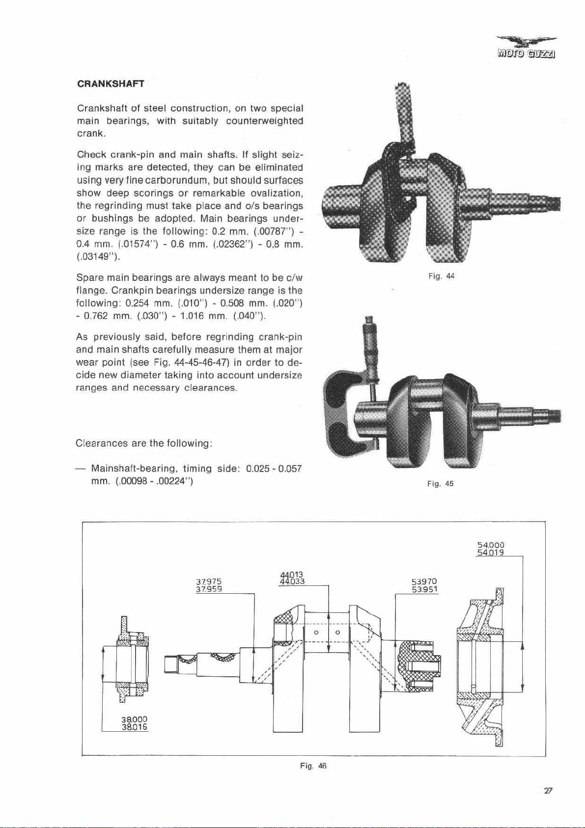
Fig. 39
clea
rance must be 0.3
40)
and
tighten
wrench at 3.500
Fig
42
shows
to
measurements. refer
dismantled
.
nuts by
Kg
/m. (25.31
to
con-
Fig.
Fig.
3B
.-
•
•
. ,
•
.
"
,to
,
•
.
,
•
.
: 1,
•
..
, ,
Fi
g. 40
25
--.~
....
....
-, . '
.
••
.
..
..
.....
....
..
,
.. , •••••
..
.
..
..
!:
..
-.
.
.
.
":::1
..
'.
~
Fig. 41
22.020
22.041
22.001
22.006
25
.030
2~050
1.534
1543
26
47
47
•
.130
.142
CRANKSHAFT
Crankshaft
main bearings, with
of steel
construction,
suitably
on
two
special
counterweighted
crank.
Check
ing marks are
crank-pin
detected,
and main shafts. If
they can
be
slight
seiz-
eliminated
using very fine carborundum, but should surfaces
show
the
or
size range is the
0.4
deep sea
regrinding
bushings
mm.
(.01574") - 0.6
rings
must take
be
adopted.
following:
or
remarkable
place
Main
mm.
ovalization,
and
ols
bearings
bearings
0.2 mm. (.00787") (.02362") - 0,8
under-
mm.
(.03149").
Spare
flange.
following:
- 0.762 mm. (.030") - 1.016 mm. (.040"),
As previously said, before
and main shafts
wear
cide
main bearings are always meant to
Crankpin
0.254 mm. (.010") - 0.508 mm. (.020")
bearings undersize range is the
regrinding
point
new
carefully
(see Fig. 44-45-46-47) in
diameter
taking
measure them at
order
into
account
be
c/w
crank-pin
major
to
de-
undersize
ranges and necessary clearances.
Fig. 44
Ciearances are the
Mainshaft-bearing,
mm. (.00098 - .00224")
following:
timing
side:
0.025 - 0.057
Fig.
45
Fig. 4S
17
Mainshaft-bearing, flywheel side: 0.030 - 0.068
mm. (.00118 - .0027")
Crankpin-bearing:
.0024")
Static
balancing
plying a weight
(3.112
When
which
mm. (.118")
lb •.
).
regrinding
are
1.5 mm. (.059") for
for
Original
diameter
53.97a mm. 53.770 mm. 53.570 mm . 53.370 rnm.
(2
.1248") (2.1169
53.931
mm.
(2.1233") (2.1162")
0.011
- 0.061 mm. (.0004-
of
crankshaft
of Kg. 1.586 ±
, restore
is obtained by ap-
.0
15 on crankpin
shoulder
relief radiuses,
crankpin
mains haft, flywheel side.
DIAMETER OF MAINSHAFT, FLYWHEEL SIDE
0.2 mm.
(.00787
")
")
53.751
mm.
DIAMETER OF MAINS HAFT, TIMING SIDE
and 3
Undersize
0.4 mm . 0.6 mm.
(.
01574
")
(2.1090")
53.551
mm
(2.1033") (2.1004")
.
(.02362")
(2.1013")
53.351
mm
0.8 mm.
(.03149")
53.170 mm.
(2.093")
mm
.
53.151
(2
.0926")
.
Original
illmeter
d
37.975 Mm.
(1.4951··) (1.4872") (1.4793·
37.959 mm.
(1.4944") (1.4866
0.2 mm. 0.4 mm. 0.6 mm.
")
(.00787
37.775
mm.
37
.759 mm . 37.559 mm . 37.359 mm.
")
(.01574
37.575 mm. 37.375 mm.
(1.4787") (1.4707")
110 OF MAIN BEARING, FLYWHEEL SIDE
Or
igin
al
diameter
54.000 mm .
(2.1260")
54.019
mm.
(2.1267")
0.2 Mm. 0.4 Mm . 0.6 mm.
(.00787")
53
.800 mm 53.600 mm
(2.11 71")
53.819
mm.
(2.1188'
·)
(.01574")
(2.11
53
.619 mm .
(2.1109")
110 OF MAIN BEARING, TIMING SIDE
Original
diameter
0.2 mm.
(.
00787
")
0.4 mm .
(.01574
")
02")
")
Undersize
·)
Undersize
Undersi
(.02362")
(1.4715" )
(.02362
53.400
(2
53.419 mm.
(2.1031
ze
0.6 mm.
(.02362")
")
mm.
.1024")
")
mm.
0.8
(.03149" )
37.175 mm.
(1.4636")
37.159 mm.
(1.4629")
0.8 mm.
(.03149
")
53.200 mm.
(2.0945")
53.219 Mm.
(2
.0952")
0.8
mm.
(.03149")
28
mm. 37.800 mm.
38.000
(1.496''')
38.016 mm . 37.816
(1.4967
")
(1.4883")
(1.4889" )
mm.
37.600 mm.
(1
.4803") (1.4725")
37
.616 mm . 37.4
(1.4809") (1.4731")
37.400 mm .
16
mm.
37
.200 mm.
(1.5646
37
.216 mm.
(1
.5652
")
")
 Loading...