

MOTO GUZZI Stornello sportcc, Stornello sport 125 cc Owner's Manual

STORNEllO
SPORI
125
cc
RIDER'S
HANDBOOK
s " ( l
lllil
110111.
OIL


MOTO
GUZZI
SOCIETA
PER
AZIONI
STAB
ILlMENt O E AMMINISTRAZIONE :
Mandello
del Lario (Co
mo)
Via Emanuele V. Parodi,
57
Telefoni:
Mandello Lar
io
71
.112
(4
linee
con ricerca
autom at!ca
)
Le
eco
22.691
Collegamento
ponte-radio con Milano e Genova
Tel
egrammi:
Motoguzzi -
Mande
llo Lario
SEDE
LE
GA
LE :
Milan
o
Vi
a D
urini
N.
28
Telefoni :
705.784 -705.785
- Tele
grammi:
Motoguzzi
Milano
FILIALE
-
CENTRO
R I
CAMBI
Mi
lano
(640)
- Via
Giovanni
da '
p,r-C;it
ida, 14
Tel
efoni:
.<841.42 1
/341.296/381.997/384.033
Telegr
.:
Filialmotoguzzi - Milano
UFFICI :
Genova
- C.so
Aurelio
Saffi,
29
Telefoni :
55.242/55.243/55.244/55.245
T
elegrammi:
Peromer
• G
nova
Ro
ma
• Via
Barberlnl,
S6
. Telefono
484.758
T
elegremml:
Motoguzzi - Roma
Napoli - Piazza
Municipio,
84
- Telefono
310
.581
Tel
egrammi:
Motoguzzi - Napo li
Torino - Corso Unione Sovietica,
70
- T
elefono
500.
173
Tel
egrammi:
Motoguzzi - Torino
STORNEllO
SPORT
125
cc
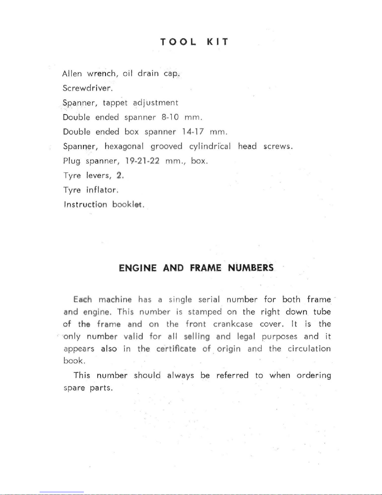
TOOL
KIT
Allen
wr
ench
, oil
drain
cap:
Screwdriver
.
Spanner,
tapp
et
adjustmen
t
Double
ended
spanner
8-10
mm
.
Double
ended
box
spanner
14
-17
mm.
Spanner
, h
exagonal grooved
cylindriCal
head
icrews.
Plug spann
er,
19
-21-22
mm.,
box.
Tyre levers,
2.
Tyre
inflator
.
Instru
ction
booklet.
ENGINE
AND
FRAME
NUMBERS
E
c:h
machine
has
a sing le
seri
al
number
for
both
frame
and
engine
. This
number
is
stamped
on
the
right
down
tube
of
the
frame
and
on
the
front
crankcase
cove r. It is
the
onl y
numb
er
valid
for ell
$elling
end
legal
purposes
and
it
app
ears
also
in
the certlfleete
of. origin
and
the
circu
lation
boo
k.
This
number
should
always
be
referred
to
when
orde
ring
spa
re
parts
.
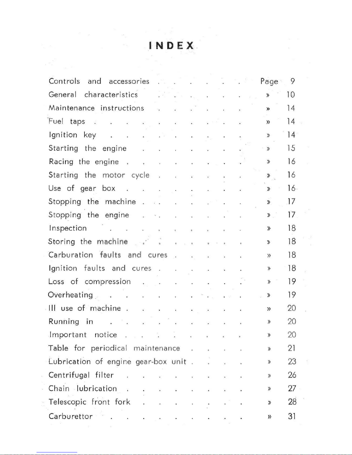
INDEX
Control
s
and
accessories
Page
9
General
characteristics
»
10
Maintenance
instructions
»
14
f=uel
taps
»
14
Ignition
key
» 14
Starting
the
engine
15
Racing the e
ngin
e
16
Starting
the
motor
cycle
16
Use
of
gear
box
»
16
Stopping
the
machine
»
17
Stopping
the
engin
e
17
Inspection
»
18
Storing
th
e
m
achIne
»
18
Carburat
ion
faults
end
cures
»
18
Ignition
fault
s
and cur
es
18
Loss
of
compressi
on
19
Overheating
19
III use
of
machine
»
20
Running
in
20
Important
notice
»
20
Table
for
periodical
maintenance
21
Lubrication
of
engin
e
gear-box
unit
23
Centrifugal
filter
»
26
Chain
lubrication
»
27
Telescopic
fr'ont
fork
»
28
Carburettor
»
31
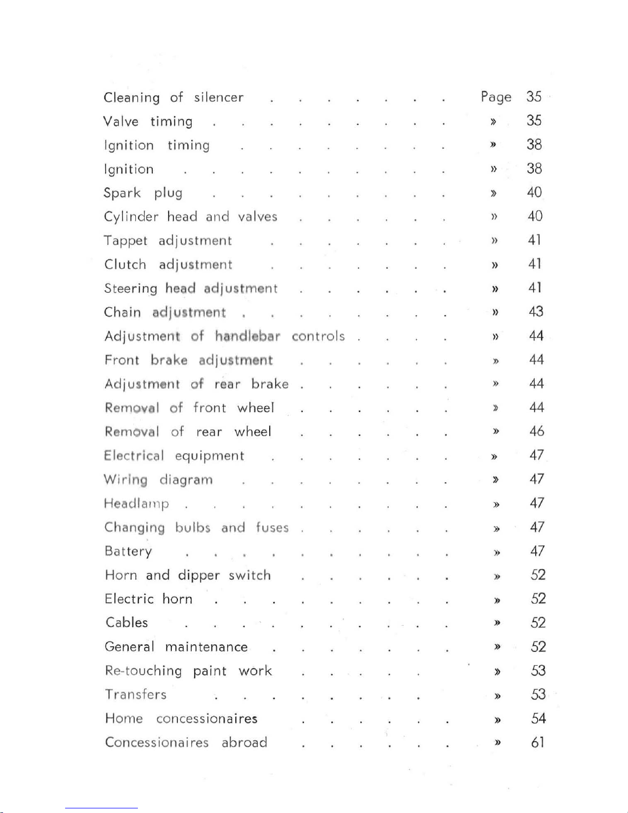
Cleaning
of
silencer
Page
35
Valve
timing
»
35
Ignitio n
timing
»
38
Igniti
on
»
38
Spark
plug
»
40
Cylinder head
and
val
ves
»
40
Ta
ppet
adjustm
en
t
»
41
Clutch
adjus
tme
nt
»
41
Steering head
adjustment
»
41
Chain
adjustment
»
43
Adju
stment
of h
andl bar
contro
ls
»
44
Fr
ont
brllke
ad
j u
stment
"
44
Adju
stment
of
rear
brak
e
»
44
Removel
of
fron
t wheel
44
R
emove
l
of
rear
whee
l
»
46
Electrical equi
pmen
t »
47
Wiring
diagram
»
47
Headlalllp
»
47
Changing
bulbs
end
fuses
»
47
Battery
»
47
Horn
and
dipper
switch
»
52
Elec
tric
horn
"
52
Cables
»
52
Genera
l
maintenance
»
52
Re-to
uch
i ng
paint
work
»
53
Tran
sfe
rs
»
53
H
ome
co
ncessiona
ires
»
54
C
oncess
ionai res
abro
ad
»
61
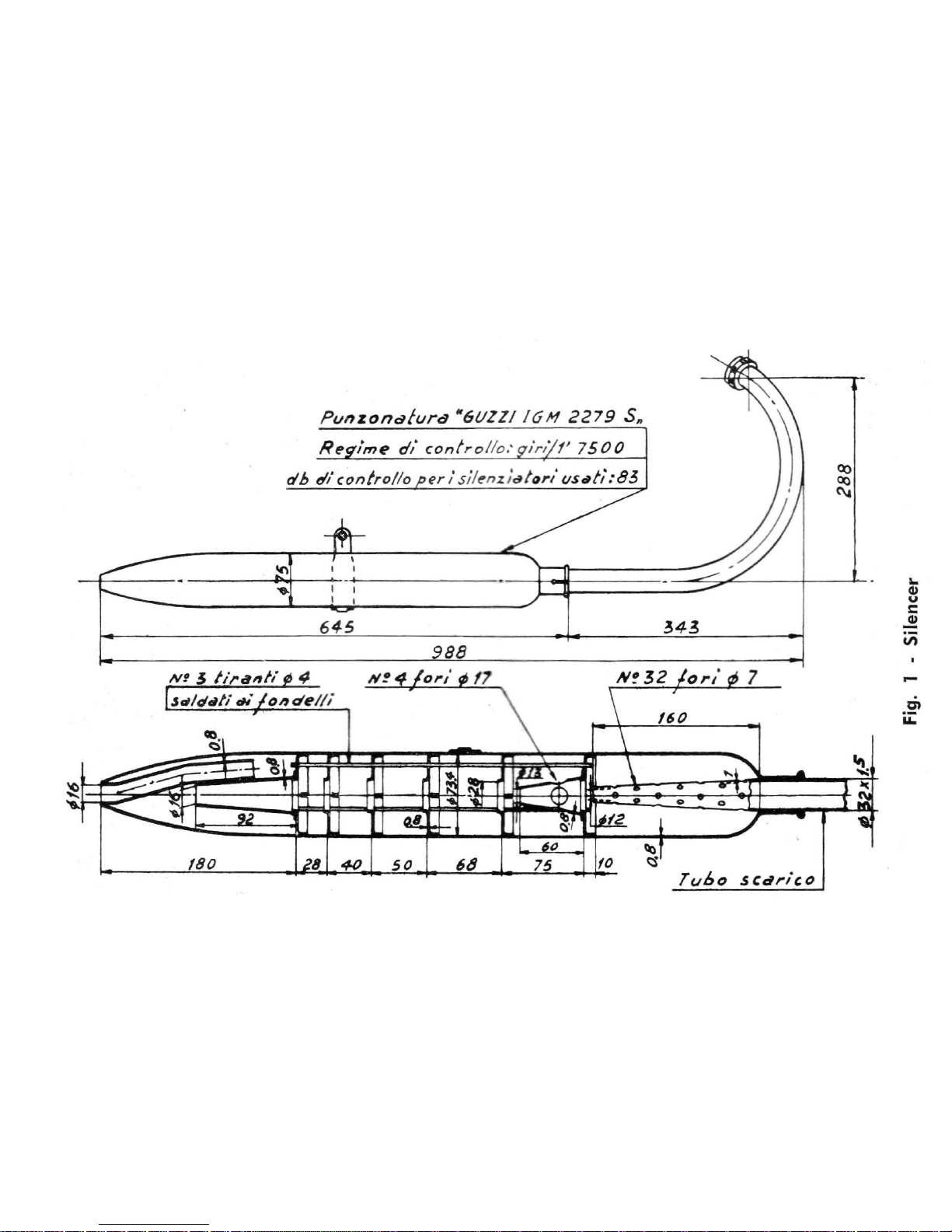
Punzonafura
"6l1ZZIIGM
2279
Sn
645
~
180
50
68
75
10
34~
TUbO
sCd,.i,()
~
CO
C\a
...
QI
u
C
~
iii
til
u:::
.
~
u..
-
..t:
tn
"
;:
01
u
>-
u
...
o
o
:E
M
tn
i.L
9
1 -
----
-JC-_
2-
----t----<
r-
""-'"
_______
'"
10
3
--~~1m
~~~
~~
4
5
---
--I--+
~
12
7---
--==~
Fig
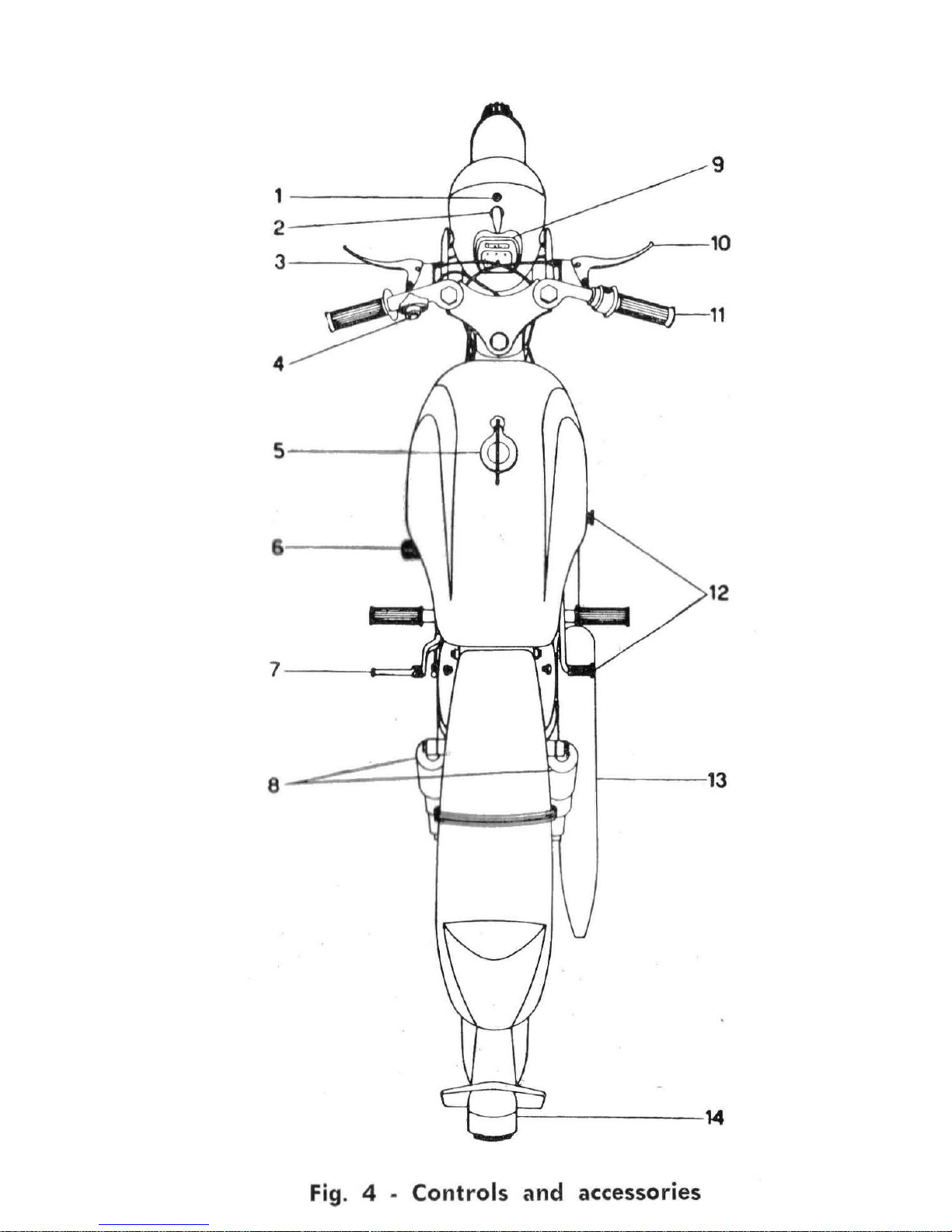
. 4 . Controls and accessories
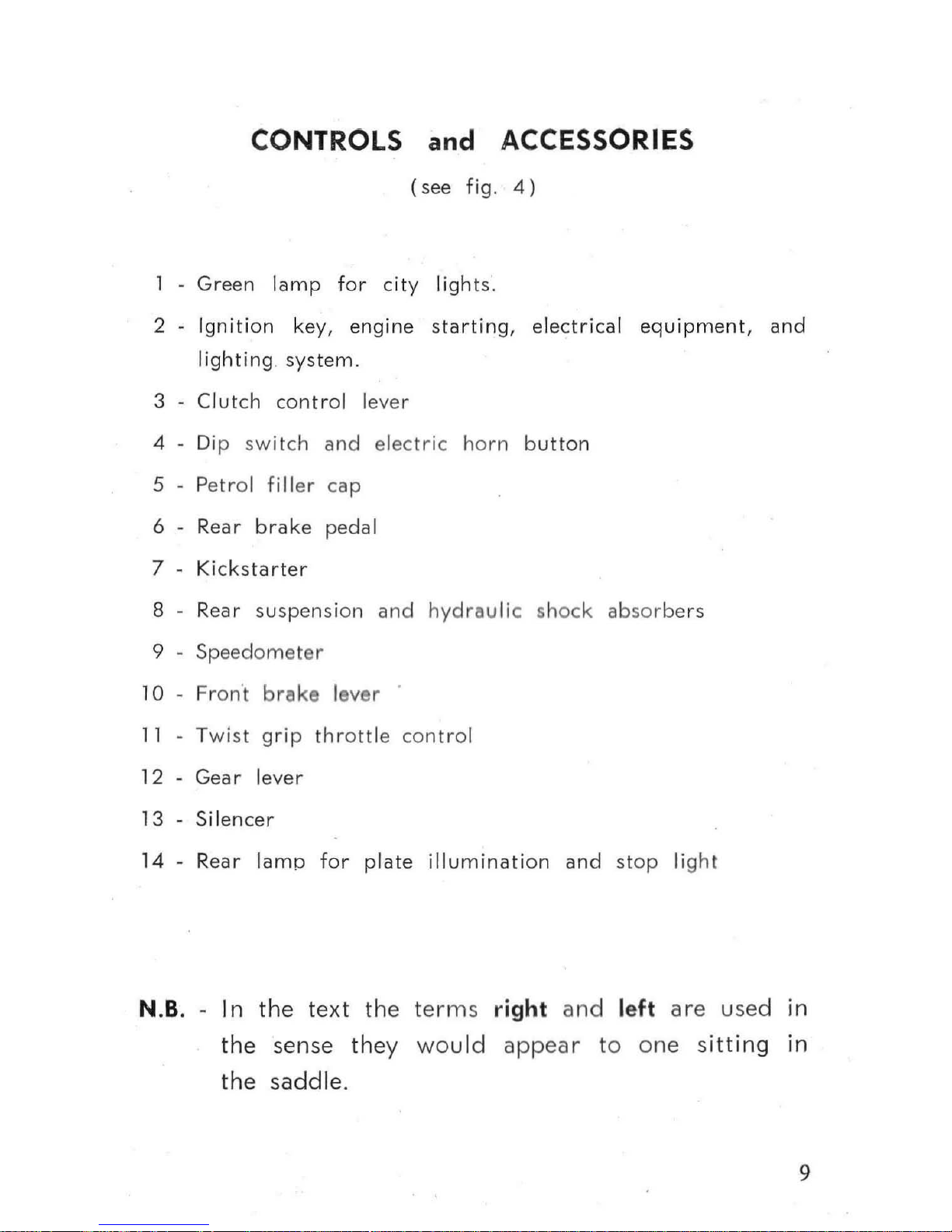
CONTROLS and ACCESSORIES
(see
fig.
4)
Green
lamp
for
city
light
s.
2
Ignition
key,
engine
starting, electrical
equipment,
and
lighting
system
.
3
Clutch
control lever
4 Dip
switch
and
electric
horn button
5 P
etrol
fi Iler
cap
6
Rear
brake peda
l
7
Ki
cks
tarter
8 R
ear
su
spe
nsion
and
hydrau
lic shock
absorbe
rs
9
Speedometer
10 - Fron·t
brake lev
er
11
Twist grip
throttle
control
12
Gear
lev
er
13
Silencer
14 -Rear
lamp for
plate
illuminati
on
an
d st
op
light
N.B. - I n
the
te xt
the
ter
ms
right
and
left are
used
in
the
sen
se
they
wo
uld
appear
to
one s
itting
in
the
saddle
.
9
Engine
GENERAL CHARACTERISTICS
ENGINE
Single cyl
inder four
stroke,
O.H.V.
Cylinder
In
lig
ht
alloy
with
special
cast
iron
inserted liner,
25" incli-
n
ation
.
Cylinder he d
In light
alloy
with
valve
gear
runn
ing in
Valve r
operation
Pu
sh
rod
and
rockers.
Stroke
Bore
Swept
vol
ume
R
tlng
Output
Compress
ion ratio
Ignition
o
il
bath
.
6
V -
:28
W
~
ywh
I alternator
with
remote
H.T. coil.
58
mm.
52 mm.
125
cc.
2 HP
8.5 HP
9.8
to 1
N.B. - Make sure the ba
ttery I. alway. on whilst
ri
ding Or the rectifier
might soon get damaged.
Plug
Marelli
CW260L
Fuel
High
octa
ne
petrol.
Petrol
tank
capacity
about
14
.5
liters
(3
and 1/4 gls. ). Tw
ist
grip
contr
olled
carburettor,
Dell'Orto
make
type
ME
18
BS with
air
filter a
nd
inlet silencer
type
B 20
B.
10
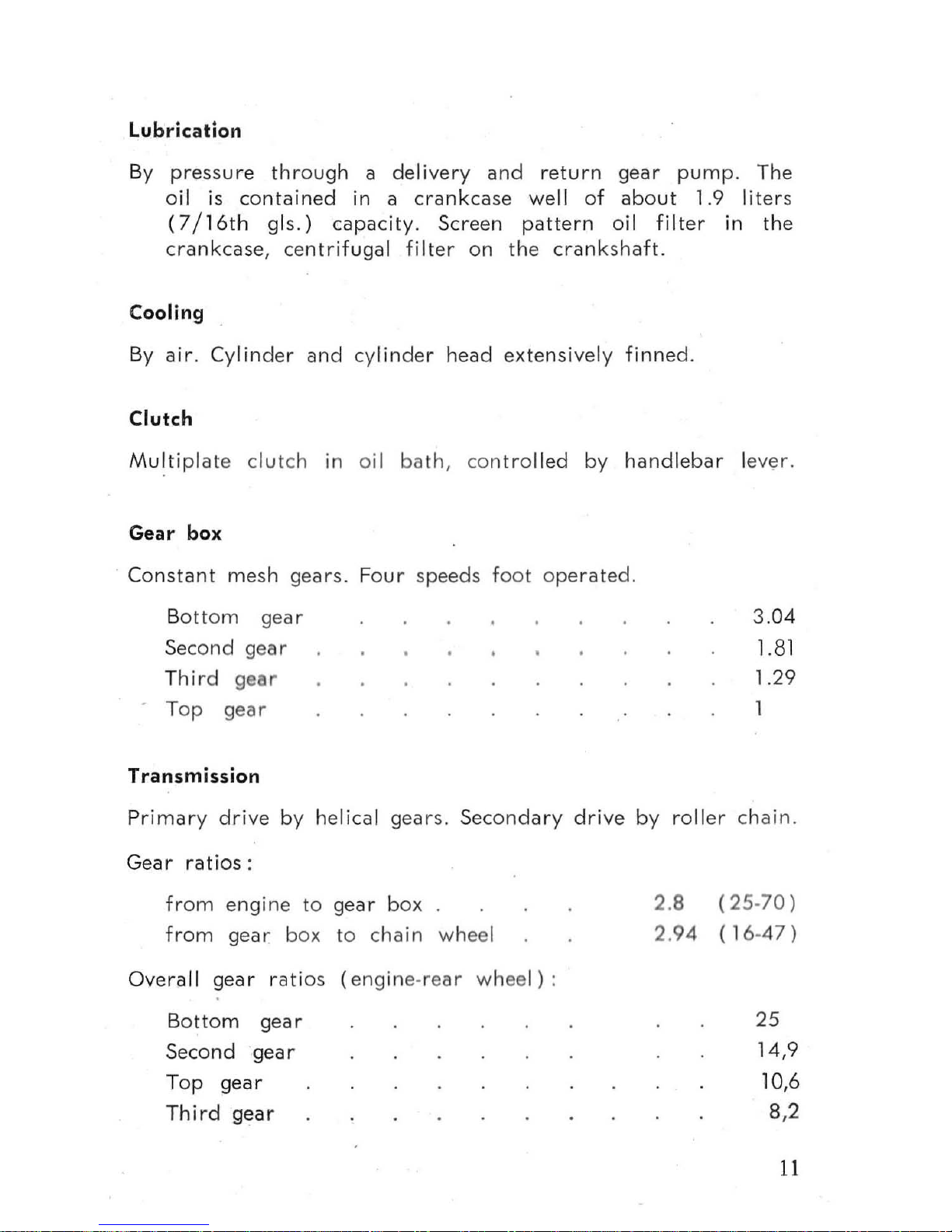
Lubrication
By
pressure
through
a
delivery
and
retu rn
gear
pump.
The
oil is
contained
in
a
crankcase
well
of
about
1.9
liter
s
(7/16th
gls.)
capacity. Screen
pa
ttern
oi l
filter
in
the
crankcase,
centrifugal
filter
on
the
crankshaft.
Cooling
By
air. Cylinder
and
cyl
inder
head
extens
ively
finned
.
Clutch
Multipl
ate
clut
ch
in
oil
bath,
controlled by
handlebar
le
ver
.
Gear
box
Constant
me
sh
gears. Four
speeds
foot
operated.
Bott
om
gear
Second
gear
Thi
rd
gear
T
op
gear
Transmission
3.04
1.81
1.29
Primary drive
by helical
gears.
Seco
ndary
drive
by
roller
chain.
Gear
ratios:
from
engine
to
gear
box
from
gear
box
to
chain
wheel
Overall
gear
rati
os (engine·rear
wheel)
:
Bottom
gear
Second
gear
Top
gear
Third
gear
2.8
2.94
(25·70)
( 16·
47)
25
14,9
10,6
8,2
11
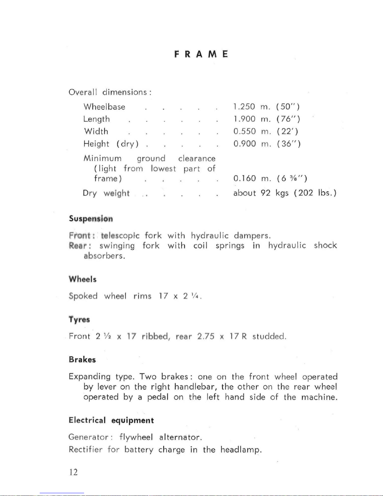
Overa
ll
dimensions:
Wheelbase
Length
Width
Height
(dr
y ) .
F
RAM
E
Minimum
gro u
nd
clearance
(light
fr
om l
owe
st pa
rt
of
fra
me
)
Dry
we
igh
t
Susp
e
Ion
1.2
S0
1.9
00
O.SSO
0.900
0.160
about
m.
(SO
" )
m.
(76
" )
m.
(22')
m.
(36
" )
m.
(6
%
")
92 kgs
(202
Pr
on : , I s
copic fork
with hy d raulic
dam
pers
.
Ibs. )
Rear:
swin
ging
fork
with
coil
springs
in hy
draulic
shock
absorbe
rs.
Wheels
Spoked
wheel rims 17 x 2 'I • .
Ty"
Fro
nt
2 '/2 x 17 rlbbe
d, rea
r
2.75
x 17 R stu dded.
Brakes
E
xpand
ing t
ype. Two
brakes:
one
on
the
front
wheel operated
by
lever
on
the
right
handlebar,
the
other
on
the
rear
wheel
operated
by a pedal
on
the left
hand
side
of
the
machine
.
Electrical equipment
Gene rato r :
flywheel
alternator
.
Rectifier for
battery
charge
in
the
headlam
p.
12
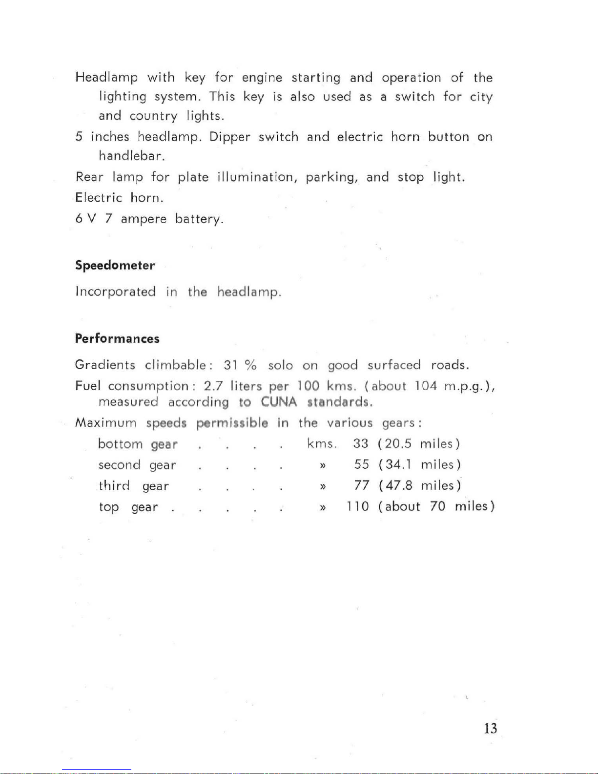
Headlamp
with
key
for
engine
start
ing
and
operation
of
the
lighting
system.
This key is
also
used
as a
switch
for
city
and
country
lights.
5 inch
es
headlamp
. Dipp
er
sw
itch
and
electric
horn
button
on
handlebar
.
Rear
lamp
for
plate illumin
ation,
parking,
and
stop
light.
Electric
horn
.
6 V 7
ampere
battery
.
Speedometer
Inc
orporat
ed in the h
eadlamp.
Performances
Gradients
clim
babl
e:
31 %
so
lo
on
goo
d s
urf
aced
roads.
Fuel
consumpti
on : 2 .7 lit
ers
per 100
km
s. (
abo
ut 104
m.p.g.),
mea s u r
ed
acco
rding
to
CUNA standard
s.
Maximum
speed
s pe
rmissibl
e in t
he
vario
us
gears
:
bott
om
gear
km
s.
33
(20.5
miles)
second
ge
ar
})
55
(34.1
miles )
thire!
gear
})
77
(47
.8
miles)
to p
gear
.
})
110
(about
70
miles)
13
MAINTENANCE
INSTRUCTIONS
Before st
arting
make
su
re th
ere
is
sufficie
nt
petrol in
tbe
crankcase
well. Oi l level
is
checked
by
means
of
the dipstick
welded
on
to
the fill
er
cap.
Correct oil
level is in
between
the
minimum
and
maximum
marks
(fig. 5 ). Thi s c
heck
shou
ld
be
made
with
the
filler
cap
unsc r
ewed.
Under
no
circumstances
should
hills
be
descended
with
the
g
ear
in
neutral
or
the clutch
disengaged.
It
is
far
better
to
ut
ilize the
braking
effect of
the
engine with
the
throt
tle
control
at
min
imum
open.in
g.
Steep
hills s
hould
be
descended
in
th
e
l
ower gears,
as this will
save
ove
rheating
of
the
drum
s
and
wear
of
th linings.
On
w t
or
slippery
roads
proceed
with
the
ut
most
cere,
avoidin
9 viole
nt
ac
cele
ration
and/or
fierce
braklngs. In
such co
nditi
ons, it
Is
well to
consider decreasing
slightly
the
tyre
pressure.
Hills s
hould
be climbed
in
the
gear
which
allows
the
eng
ine
to
run
at
no
rmal
revolutions. Under
no
circumstances
whatever
sho
uld
hills
be
climbed
by
slipping
the
clutch. This
wo
uld
repidly
wear
the
plates
out.
Particular
care
shou
ld be
taken
not
to
exceed the
maximum
speeds
in
the
diff r
nt
gears
specified
in
« Pe
rform
ances:>.
Fuel taps
The left
tap
is
th e
reserve
tap
and should
be
kept
closed
for
use
in
an
emergency
only
: H
owever,
it is
1)
goed rule
to
oc
casionally check
its efficiency
and
to clec:n
it
out
if
obstructed
by
grit
or
other
foreign
matter
.
Ignition key
Before
the
eng
ine can
be started
or
the electrical equipment
used,
it is
necessa
ry
for
the
ignition
key to
be
pushed
right
14

down
in its «
contact»
position.
To
stop
the
engine,
the
key
should
always
be
withdrawn
from
contact.
Starting the engine
To
start
the
eng
ine
from
cold:
open
right
hand
fuel
tap,
check
if
gear lever
is in
neutra
l,
push
ignition
key
down
in
its
Fig.
5
15
co
ntact
positi
on,
turn
twist
gr
ip light
ly,
push
down
ca
rburettor
a
ir
slide
(Fig. 11
A), and
depress
the kickstarter sha
rply.
One
or
two
kick
are
genera
lly s
ufficient
to
start
the
eng
ine.
When starti
ng
fr
om
co
ld,
and
especially in w
int
er
tim
e,
it is
convenient
to
sl i
ghtly flood the
carburettor,
taking
care
not
to
overdo this
as
it
may
th
en
make
star
ting
rather
dif-
ficult.
This is
unnecessary
to
start
a
hot -eng
ine.
In
the
cold season,
it is well
to let
the
engine
idle a
shor
t
while
to
allow
the o il to
war
m
up
befo re
taking
off.
Be sure
to
res
tore
the
air sli
de to its o
rigin
al r
iding position
.
N.B. - This engin e can also
be
star
ted with
an
engaged
gear
by
depressing
the
kickst
arter
with
the
clutch
withdrawn
.
Racing the engine
Under
no circumste
nc s wh
ateve
r s hou ld
th
e
engine
be
al l
ow
d
to
run
at
high
revo
lutions b
efo
re ta
king
off.
Starting
the
motor
cycle
After the
eng ine is started , w
ithdraw
fully
the
clutch lever,
engage
bottom
gea
r,
and slow
ly re lease the c
lutch
accelerating
the
engine at
th
sam
ti
me
as the c
lut
ch s
tarts
to
« b ite ».
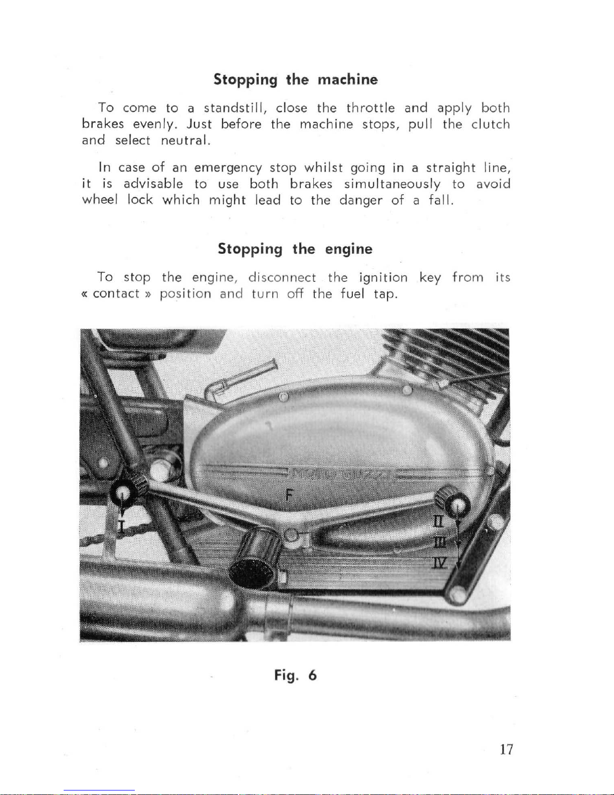
U
se
of
gear- box
(s fig.
6)
To
change
to a
high
er
gear,
the
thrott
le sho
uld
be shut
a
nd
th
e cl
utch simultane
ously w
ith
drawn,
moving
the
gear
leve r in
the
ne
xt p
osition.
The
clut
ch
shou
ld then
be
rele
ased
slow ly
and
the
throttle gradually
re-op
ened.
To
change
down,
the
pr
ocedure
is reve r
sed,
exce
pt that
the
throttle
sho
uld
not
be
co
mpl
etel y cl
ose
d.
Change
up
rather
than let
the
engine
race.
Change dow
n
rather
than
let is s log.
16
Stopping the machine
To
come
to
a
standsti
II,
close
the
throttle
and
apply
bo
th
brakes
evenly.
Just
before
the
machine
stops,
pull
the clutch
and
select
neutral.
In
case
of
an
emergency
stop
whilst
go
ing in a
straight
line,
it is
advisable
to
use
both
brakes
sim
ult
aneously
to
avoid
wheel
lock
which
might
lead
to
the
danger
of
a fall.
Stopping the engine
To
stop
the
en
gin
e, disconnect the
ignition
key
from
its
«
contact
})
pos
iti
on
and
turn
off
the
fuel
tap.
Fig.
6
17
Inspection
After
a
wet
ride or
one
over
particularly
bad
roads,
the
machine
should
always
be
checked
over
externally
and
dried.
Storing the machine
If
the
machine
is
being
put away
for
a fairly
long
period
:
-
Thoroughl
y
clean
the
mach
ine
«see
Periodical
Main-
tenance
».
-
Intr
oduce
a little o
il
into
the
cylind
er
through
the
plug
hole
and revo
lve the
eng
ine a
few
times
to
even
ly
distribute
the
oil
over
th e cylinder
wa
lls.
- Raise
the
machine
so
that
the
tyres
are
out
of
contact
with
th e
grou
nd,
especiall
y if
the floo
r is
slippery
or
greasy.
~
Cover
with V s lin
or
antirust
co
mpound
all
metal
parts
not
namelled.
Carburation faults and cures
If
the
engine will not
sta
rt
or stops
suddenly,
the
cause
may
be
one of the
following
:
-
Lack
of
fu
I.
Ch
ck
if
there
is fuel in
the
tank,
also
if
the
tap
is
open.
--
Ob$truc-tlon 0
blow
throu
gh 0 r
fu I
pipes
and/o
r
filters.
Clean
and
th
ob
true
Ion .
-
Carbu
rettor
I ts
obstruet
d. CI
an
with air
jet.
Ignition faults and cures
If
the
engine
will
not
start
and
the
carburation
is in
order,
s
uspect
the
fault
in
the
ignition.
Check
if
there
is
a
spark
at
the
plug
by
holding
its
body
against
the
cylinder
and
revolving th e
eng
ine
with
the
kicks
tarter
.
18
 Loading...