

MOTO GUZZI STELVIO 4V - 1200 ABS Service Station Manual
SERVICE STATION MANUAL
895790
STELVIO 4V - 1200 ABS

SERVICE STATION
Revente Interdite - Revendita Vietata - Resaling Forbiden - Wiederverkauf Verboten
MANUAL
STELVIO 4V - 1200 ABS
THE VALUE OF SERVICE
Only the mechanics of the official Moto Guzzi Service Network know this vehicle well, thanks to constant
technical professional development and Moto Guzzi specific training programmes, and have the tools
needed to carry out maintenance and repair operations correctly.
The reliability of the vehicle also depends on its mechanical conditions. Checking the vehicle before
setting off, carrying out routine maintenance and using only Moto Guzzi Original Spare parts is
fundamental!
For information about the nearest Official Dealer and/or Service Centre, consult the Yellow Pages or
search directly on the inset map in our Official Website:
www.motoguzzi.it
Only by purchasing Moto Guzzi Original Spare Parts will you get a product designed and tested during
the bike designing phase. Moto Guzzi Original Spare Parts are subject to systematic quality control
procedures so that their reliability and performance over time is guaranteed.
The descriptions and illustrations given in this publication are not binding; while the basic features as
described and illustrated in this manual remain unchanged, Moto Guzzi reserves the right, at any time
and without being required to update this publication beforehand, to make any changes to components,
parts or accessory supplies, which it deems necessary to improve the product or which are required for
manufacturing or commercial reasons.
Not all versions shown in this publication are available in all countries. The availability of individual
versions should be checked with the official Moto Guzzi sales network.
© Copyright 2010 - Moto Guzzi. All rights reserved. Reproduction of this publication in whole or in part
is prohibited. Moto Guzzi - After sales service.
The Moto Guzzi brand is owned by Piaggio & C. S.p.A.

SERVICE STATION MANUAL
Revente Interdite - Revendita Vietata - Resaling Forbiden - Wiederverkauf Verboten
STELVIO 4V - 1200 ABS
This manual provides the main information to carry out regular maintenance operations on your vehicle.
This manual is intended to Moto Guzzi Dealers and their qualified mechanics; several concepts have
been deliberately omitted as they are considered unnecessary. As it is not possible to include complete
mechanical notions in this manual, users should have basic mechanical knowledge or minimum
knowledge about the procedures involved when repairing scooters. Without this knowledge, repairing or
checking the vehicle may be inefficient or even dangerous. As the vehicle repair and check procedures
are not described in detail, be extremely cautious so as not to damage components or injure individuals.
In order to optimise customer satisfaction when using our vehicles, Moto Guzzi s.p.a. commits itself to
continually improve its products and the relative documentation. The main technical modifications and
changes in repair procedures are communicated to all Moto Guzzi Sales Outlets and its International
Subsidiaries. These changes will be introduced in the subsequent editions of the manual. In case of
need or further queries on repair and check procedures, consult Moto Guzzi CUSTOMER
DEPARTMENT, which will be prepared to provide any information on the subject and any further
communications on updates and technical changes related to the vehicle.
NOTE Provides key information to make the procedure easier to understand and carry out.
CAUTION Refers to specific procedures to carry out for preventing damages to the vehicle.
WARNING Refers to specific procedures to carry out to prevent injuries to the repairer.
Personal safety Failure to completely observe these instructions will result in serious risk of personal
injury.
Safeguarding the environment Sections marked with this symbol indicate the correct use of the vehicle
to prevent damaging the environment.
Vehicle intactness The incomplete or non-observance of these regulations leads to the risk of serious
damage to the vehicle and sometimes even the invalidity of the guarantee.
Revente Interdite - Revendita Vietata - Resaling Forbiden - Wiederverkauf Verboten

INDEX OF TOPICS
Revente Interdite - Revendita Vietata - Resaling Forbiden - Wiederverkauf Verboten
CHARACTERISTICS CHAR
SPECIAL TOOLS S-TOOLS
MAINTENANCE MAIN
ELECTRICAL SYSTEM ELE SYS
ENGINE FROM VEHICLE ENG VE
ENGINE ENG
POWER SUPPLY P SUPP
SUSPENSIONS SUSP
CHASSIS CHAS
BRAKING SYSTEM BRAK SYS
BODYWORK BODYW
PRE-DELIVERY PRE DE

INDEX OF TOPICS
Revente Interdite - Revendita Vietata - Resaling Forbiden - Wiederverkauf Verboten
CHARACTERISTICS CHAR

STELVIO 4V - 1200 ABS Characteristics
Revente Interdite - Revendita Vietata - Resaling Forbiden - Wiederverkauf Verboten
Rules
Safety rules
Carbon monoxide
If you need to keep the engine running while working on the vehicle, please ensure that you do so in
an open or very well ventilated area. Never run the engine in an enclosed area. If you do work in an
enclosed area, make sure to use a fume extraction system.
CAUTION
EXHAUST EMISSIONS CONTAIN CARBON MONOXIDE, A POISONOUS GAS WHICH CAN CAUSE
LOSS OF CONSCIOUSNESS AND EVEN DEATH.
Fuel
CAUTION
THE FUEL USED TO POWER INTERNAL COMBUSTION ENGINES IS HIGHLY FLAMMABLE AND
MAY BE EXPLOSIVE UNDER CERTAIN CONDITIONS. IT IS THEREFORE RECOMMENDED TO
CARRY OUT REFUELLING AND MAINTENANCE PROCEDURES IN A VENTILATED AREA WITH
THE ENGINE SWITCHED OFF. DO NOT SMOKE DURING REFUELLING OR NEAR FUEL VAPOUR.
AVOID ANY CONTACT WITH NAKED FLAME, SPARKS OR OTHER HEAT SOURCES WHICH MAY
CAUSE IGNITION OR EXPLOSION.
DO NOT ALLOW FUEL TO DISPERSE INTO THE ENVIRONMENT.
KEEP OUT OF THE REACH OF CHILDREN
Hot components
The engine and the exhaust system components become very hot and remain hot for some time after
the engine has been switched off. When handling these components, wear insulating gloves or wait
until the engine and the exhaust system have cooled down.
Used engine oil and transmission oil
CAUTION
IT IS ADVISABLE TO WEAR LATEX GLOVES WHEN SERVICING THE VEHICLE.
THE ENGINE OR GEARBOX OIL MAY CAUSE SERIOUS INJURIES TO THE SKIN IF HANDLED
FOR PROLONGED PERIODS OF TIME AND ON A REGULAR BASIS.
WASH YOUR HANDS CAREFULLY AFTER HANDLING OIL.
HAND THE OIL OVER TO OR HAVE IT COLLECTED BY THE NEAREST USED OIL RECYCLING
COMPANY OR THE SUPPLIER.
DO NOT DISPOSE OF OIL IN THE ENVIRONMENT
KEEP OUT OF THE REACH OF CHILDREN
Brake and clutch fluid
CHAR - 7
Characteristics STELVIO 4V - 1200 ABS
Revente Interdite - Revendita Vietata - Resaling Forbiden - Wiederverkauf Verboten
BRAKE AND CLUTCH FLUIDS CAN DAMAGE THE PLASTIC OR RUBBER PAINTED SURFACES.
WHEN SERVICING THE BRAKING SYSTEM OR THE CLUTCH SYSTEM PROTECT THESE COM-
PONENTS WITH A CLEAN CLOTH. ALWAYS WEAR PROTECTIVE GOGGLES WHEN SERVICING
THESE SYSTEMS. BRAKE AND CLUTCH FLUIDS ARE EXTREMELY HARMFUL FOR YOUR
EYES. IN THE EVENT OF ACCIDENTAL CONTACT WITH YOUR EYES, RINSE THEM IMMEDI-
ATELY WITH ABUNDANT COLD, CLEAN WATER AND SEEK MEDICAL ADVICE.
KEEP OUT OF THE REACH OF CHILDREN
Battery electrolyte and hydrogen gas
CAUTION
THE BATTERY ELECTROLYTE IS TOXIC, CORROSIVE AND, AS IT CONTAINS SULPHURIC
ACID, MAY CAUSE BURNING IF IT COMES INTO CONTACT WITH THE SKIN. WHEN HANDLING
BATTERY ELECTROLYTE, WEAR TIGHT-FITTING GLOVES AND PROTECTIVE APPAREL. IN
THE EVENT OF SKIN CONTACT WITH THE ELECTROLYTIC FLUID, RINSE WELL WITH PLENTY
OF CLEAN WATER. IT IS PARTICULARLY IMPORTANT TO PROTECT YOUR EYES BECAUSE
EVEN TINY AMOUNTS OF BATTERY ACID MAY CAUSE BLINDNESS. IN THE EVENT OF CON-
TACT WITH THE EYES, RINSE WITH PLENTY OF WATER FOR FIFTEEN MINUTES AND CON-
SULT AN EYE SPECIALIST IMMEDIATELY. IF THE FLUID IS ACCIDENTALLY SWALLOWED,
DRINK LARGE QUANTITIES OF WATER OR MILK, FOLLOWED BY MILK OF MAGNESIA OR
VEGETABLE OIL AND SEEK MEDICAL ADVICE IMMEDIATELY. THE BATTERY RELEASES EX-
PLOSIVE GASES; KEEP IT AWAY FROM FLAMES, SPARKS, CIGARETTES OR ANY OTHER
HEAT SOURCES. ENSURE ADEQUATE VENTILATION WHEN SERVICING OR RECHARGING
THE BATTERY.
KEEP OUT OF THE REACH OF CHILDREN
BATTERY LIQUID IS CORROSIVE. DO NOT POUR OR SPILL ON PLASTIC COMPONENTS IN
PARTICULAR. ENSURE THAT THE ELECTROLYTIC ACID IS COMPATIBLE WITH THE BATTERY
BEING ACTIVATED.
Maintenance rules
GENERAL PRECAUTIONS AND INFORMATION
When repairing, dismantling and reassembling the vehicle, follow the recommendations given below
carefully.
BEFORE DISASSEMBLING COMPONENTS
•
Before dismantling components, remove dirt, mud, dust and foreign bodies from the vehicle.
Use the special tools designed for this bike, as required.
COMPONENTS REMOVAL
•
Do not loosen and/or tighten screws and nuts using pliers or any other tools than the specific
wrench.
•
Mark the positions on all connection joints (pipes, cables, etc.) before separating them, and
identify them with different distinctive symbols.
•
Each component needs to be clearly marked to enable identification during reassembly.
•
Clean and wash the dismantled components carefully using a low-flammability detergent.
CHAR - 8

STELVIO 4V - 1200 ABS Characteristics
Revente Interdite - Revendita Vietata - Resaling Forbiden - Wiederverkauf Verboten
•
Keep mated parts together since they have "adjusted" to each other due to normal wear.
•
Some components must be used together or replaced altogether.
•
Keep away from heat sources.
REASSEMBLING COMPONENTS
CAUTION
BEARINGS MUST ROTATE FREELY, WITHOUT JAMMING AND/OR NOISE, OTHERWISE, THEY
NEED TO BE REPLACED.
•
Only use ORIGINAL Moto Guzzi SPARE PARTS.
•
Comply with lubricant and consumables use guidelines.
•
Lubricate parts (whenever possible) before reassembling them.
•
When tightening nuts and screws, start from the ones with the largest section or from the
internal ones, moving diagonally. Tighten nuts and screws in successive steps before applying the tightening torque.
•
Always replace self-locking nuts, washers, sealing rings, circlips, O-rings (OR), split pins
and screws with new ones if their tread is damaged.
•
When assembling the bearings, make sure to lubricate them well.
•
Check that each component is assembled correctly.
•
After a repair or routine maintenance procedure, carry out pre-ride checks and test the vehicle on private grounds or in an area with low traffic density.
•
Clean all coupling surfaces, oil guard rims and gaskets before refitting them. Smear a light
layer of lithium-based grease on the oil guard rims. Reassemble oil guards and bearings
with the brand or lot number facing outward (visible side).
ELECTRIC CONNECTORS
Electric connectors must be disconnected as described below; failure to comply with this procedure
causes irreparable damage to both the connector and the wiring harness:
Press the relative safety clips, if applicable.
•
Grip the two connectors and disconnect them by pulling them in opposite directions.
•
If any signs of dirt, rust, moisture, etc. are noted, clean the inside of the connector carefully
with a jet of compressed air.
•
Ensure that the cables are correctly fastened to the internal connector terminals.
•
Then connect the two connectors, ensuring that they couple correctly (if fitted with clips, you
will hear them "click" into place).
CAUTION
DO NOT DISCONNECT CONNECTORS BY PULLING THE CABLES.
NOTE
THE TWO CONNECTORS CAN ONLY BE CONNECTED IN ONE DIRECTION: CONNECT THEM
THE RIGHT WAY ROUND.
TIGHTENING TORQUES
CAUTION
REMEMBER THAT THE TIGHTENING TORQUES FOR ALL FASTENING ELEMENTS ON WHEELS,
BRAKES, WHEEL AXLES AND ANY OTHER SUSPENSION COMPONENTS PLAY A KEY ROLE
CHAR - 9
Characteristics STELVIO 4V - 1200 ABS
Revente Interdite - Revendita Vietata - Resaling Forbiden - Wiederverkauf Verboten
IN ENSURING VEHICLE SAFETY AND MUST COMPLY WITH SPECIFIED VALUES. CHECK THE
TIGHTENING TORQUES OF FASTENING ELEMENTS ON A REGULAR BASIS AND ALWAYS USE
A TORQUE WRENCH TO REASSEMBLE THESE COMPONENTS. FAILURE TO COMPLY WITH
THESE RECOMMENDATIONS MAY CAUSE ONE OF THESE COMPONENTS TO LOOSEN OR
EVEN DETACH, CAUSING A WHEEL TO LOCK OR COMPROMISING VEHICLE HANDLING. THIS
MAY LEAD TO FALLS, WITH THE RISK OF SERIOUS INJURY OR DEATH.
Running-in
Engine run-in is essential to ensure engine long life and correct operation. Twisty roads and gradients
are ideal to run in engine, brakes and suspensions effectively. Vary your riding speed during the run-
in. This ensures that components operate under both "loaded" and "unloaded" conditions, allowing the
engine components to cool.
CAUTION
THE CLUTCH MAY EMIT A SLIGHT BURNING SMELL WHEN FIRST USED. THIS PHENOMENON
SHOULD BE CONSIDERED NORMAL AND WILL DISAPPEAR AS SOON AS THE CLUTCH DISCS
GET ADAPTED.
IT IS IMPORTANT TO STRAIN ENGINE COMPONENTS DURING RUN-IN, HOWEVER, MAKE SURE
NOT TO OVERDO THIS.
CAUTION
THE FULL PERFORMANCE OF THE VEHICLE IS ONLY AVAILABLE AFTER THE SERVICE AT
THE END OF THE RUN-IN PERIOD.
Follow the guidelines detailed below:
•
Do not twist the throttle grip abruptly and completely when the engine is working at a low
revs, either during or after run-in.
•
During the first 100 Km (62 miles) use the brakes gently, avoiding sudden or prolonged
braking. That is to permit the adequate adjustment of the pad friction material to the brake
discs.
AFTER THE SPECIFIED MILEAGE, TAKE THE VEHICLE TO AN OFFICIAL Moto Guzzi DEALER
FOR THE CHECKS INDICATED IN THE "AFTER RUN-IN" TABLE IN THE SCHEDULED MAINTE-
NANCE SECTION TO AVOID INJURING YOURSELF, OTHERS AND /OR DAMAGING THE VEHI-
CLE.
Vehicle identification
SERIAL NUMBER LOCATION
These numbers are necessary for vehicle registration.
NOTE
ALTERING IDENTIFICATION NUMBERS MAY BE SERIOUSLY PUNISHABLE BY LAW. IN PAR-
TICULAR, MODIFYING THE CHASSIS NUMBER IMMEDIATELY VOIDS THE WARRANTY.
CHAR - 10
STELVIO 4V - 1200 ABS Characteristics
Revente Interdite - Revendita Vietata - Resaling Forbiden - Wiederverkauf Verboten
This number consists of numbers and letters, as in
the example shown below.
ZGULZA000YMXXXXXX
KEY:
ZGU: WMI (World manufacturer identifier) code;
LZ: model;
A00: version variation;
0: free digit
Y year of manufacture
M: production plant (M= Mandello del Lario);
XXXXXX: serial number (6 digits);
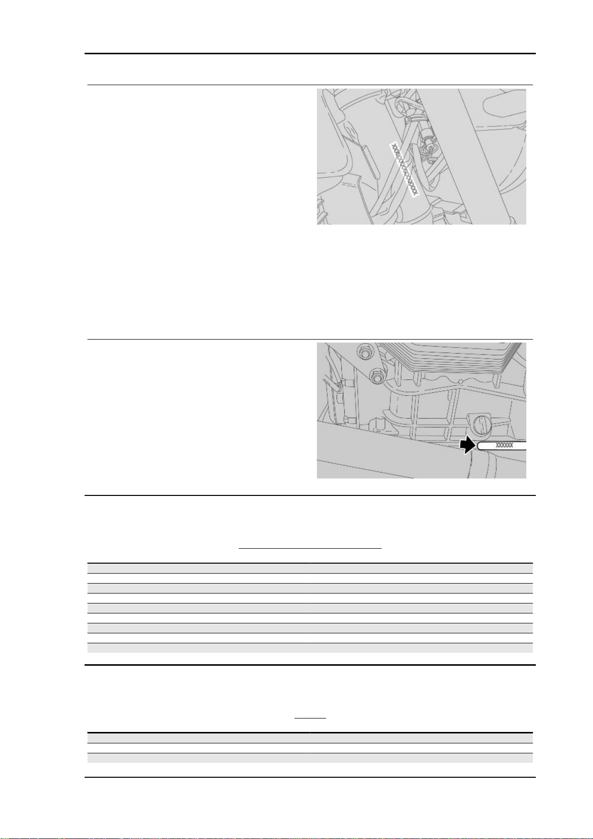
CHASSIS NUMBER
The chassis number is stamped on the right hand
side of the headstock.
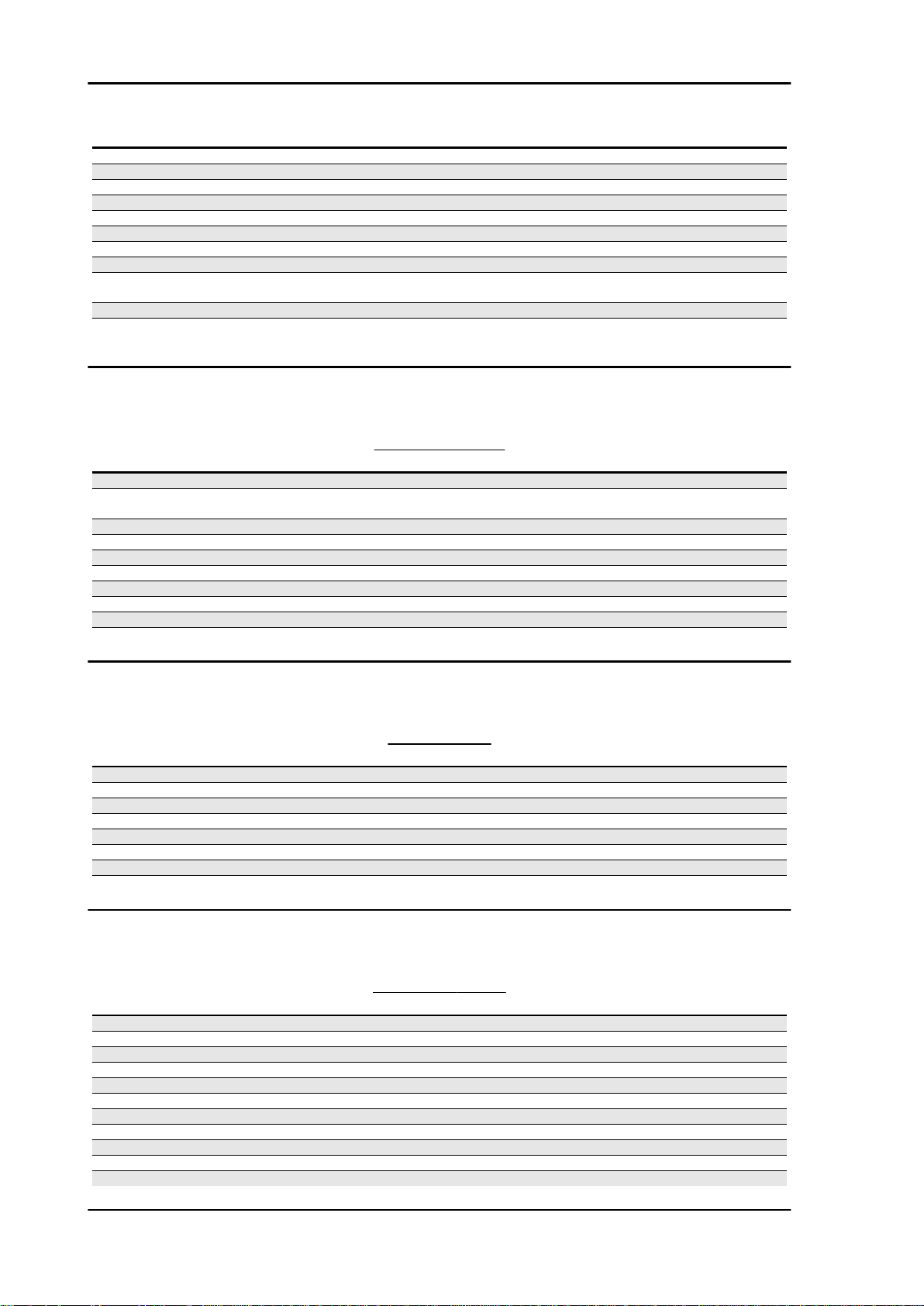
ENGINE NUMBER
The engine number is stamped on the left side,
close to the engine oil level check cap.
Dimensions and mass
WEIGHT AND DIMENSIONS
Specification
Maximum width (without accessories) 2305 mm (90.75 in)
Maximum width at handlebar 910 mm (35.83 in)
Maximum width of vehicle with accessories 1080 mm (42.52 in)
Minimum / maximum height (adjustable windshield) 1395 / 1440 mm (54.92 / 56.69 in)
Saddle height 800 mm (31.5 in)
Minimum ground clearance 185 mm (7.3 in)
Wheelbase 1535 mm (60.43 in)
Kerb weight 251 kg (553 lb)
Kerb weight of full house vehicle 278 kg (613 lb)
Desc./Quantity
Engine
ENGINE
Specification
Type four stroke 90° transverse V-twin
Number of cylinders 2
Cylinder layout 90° V
Desc./Quantity
CHAR - 11
Characteristics STELVIO 4V - 1200 ABS
Revente Interdite - Revendita Vietata - Resaling Forbiden - Wiederverkauf Verboten
Specification Desc./Quantity
Bore / stroke 95 x 81.2 mm (3.74 x 3.20 in)
Engine capacity 1151 cm³ (70 cu.in)
Compression ratio 11: 1
Ignition electric
Idle speed 1100 ± 100 rpm
Clutch hydraulic single plate dry clutch with integrated flexible coupling
Lubrication system Pressurised circuit with regulator valves and trochoidal pump
Air filter dry cartridge air filter
Cooling air/oil system with independent trochoidal pump and pressure
Timing system diagram Single overhead camshaft with bucket tappets and rockers
Values valid with control clearance between rocker and valve inlet: 0.10 mm (0.0039 in)
regulator valve for oil cooling circuit
exhaust: 0.20 mm (0.0079 in)
Transmission
TRANSMISSION
Specification Desc./Quantity
Primary drive Helical gear, ratio 26/35 = 1:1.346
Gearbox 6 speed mechanical gearbox with foot gearshift lever on left
1st gear ratio 17/38 = 1:2.2353
2nd gear ratio 20/34 = 1:1.7
3rd gear ratio 23/31 = 1:1.3478
4th gear ratio 26/29 = 1:1.1154
5th gear ratio 31/30 = 1:0.9677
6th gear ratio 29/25 = 1:0.8621
Final drive cardan shaft
Ratio 12/44 = 1:3.6667
hand side of engine
Capacities
Specification
Engine oil Oil change and oil filter replacement: 3,500 cm³ (214 cu.in)
Gearbox oil 500 cm³ (30.5 cu.in)
Transmission oil 380 cm³ (23.2 cu.in)
Fuel (reserve included) 18 ± 1.5 l (3.96 ± 0.33 UK gal)
Fuel reserve 4 l (0.88 UK gal)
Maximum weight allowed - standard version 475 kg (1047 lb)
Maximum weight allowed - NTX version 495 kg (1091 lb)
Electrical system
Specification
Spark plug NGK PMR8B (long life)
Alternatively:
Spark plug NGK CR8EKB (long life)
Electrode gap 0.6 - 0.7 mm (0.024 - 0.028 in)
Alternator (permanent magnet type) 12 V - 550 W
Main fuses 20 (two for version with ABS) - 30 - 40 A
Secondary fuses 3 - 15 A (10A for ABS only)
Front daylight running light 12V - 5W
Low/high beam headlight (halogen) 12 V - 55 W / 60 W H4
Turn indicators 12V - 10 W
CAPACITIES
Desc./Quantity
Seats 2
ELECTRICAL SYSTEM
Desc./Quantity
Battery 12 V - 18 Ampere/hour
CHAR - 12
STELVIO 4V - 1200 ABS Characteristics
Revente Interdite - Revendita Vietata - Resaling Forbiden - Wiederverkauf Verboten
Specification Desc./Quantity
Rear daylight running lights /stop light LED
Supplementary headlamps (if fitted) 12 V/55W - H3
Instrument panel lighting LED
License plate light 12V - 5 W
Turn indicator warning light LED
Neutral gear warning light LED
Alarm warning light - Shift indicator LED
Side stand down warning light LED
Low fuel warning light LED
High beam warning light LED
ABS warning light LED
Frame and suspensions
CHASSIS
Specification Desc./Quantity
Type high strength tubular steel frame with engine as stressed ele-
Trail 125 mm (4.92 in)
Headstock 27°
Front Upside down telescopic hydraulic fork, with 45mm (1.77 in) di-
am., stanchions and radial calliper mounting bracket with ad-
justable spring preload and hydraulic compression and re-
Front wheel travel 170 mm (6.69 in)
Rear single sided swingarm with progressive linkage and mono-
shock with adjustable hydraulic rebound and compression
damping and spring preloading adjustment.
Unloaded shock absorber spring length 180 mm (7.09 in)
Rear wheel travel 155 mm (6.10 in)
ment
bound damping.
Brakes
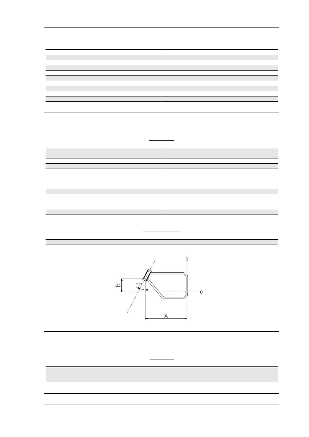
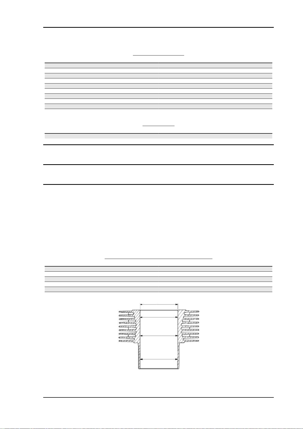
SIZES A AND B
Specification
Size A 745.0 mm (29.33 in)
Size B 403.16 mm (15.87 in)
Desc./Quantity
BRAKES
Specification
Front Dual 320 mm (12.6 in) diam. stainless steel floating wavy disc
with radial callipers with 4 differentiated, horizontally opposed
Rear 282 mm (11.1 in) diam. stainless steel disc
Desc./Quantity
pistons.
CHAR - 13
Characteristics STELVIO 4V - 1200 ABS
Revente Interdite - Revendita Vietata - Resaling Forbiden - Wiederverkauf Verboten
Wheels and tyres
WHEELS AND TYRES - STELVIO (STANDARD)
Wheel Model Rim Size Tyre pressure with
Front (standard) Pirelli Scorpion Sync 2.50 x 19" 110/80
R19 - 59V
Rear (standard) Pirelli Scorpion Sync 5.50 x 17 180/55
R17 - 73V
WHEELS AND TYRES - STELVIO (ALTERNATIVE EQUIPMENT)
Wheel Model Rim Size Tyre pressure with
Front (alternatively) Pirelli Scorpion Trail 2.50 x 19" 110/80
R19 - 59V
Front (alternatively) Metzeler Karoo (*) (***) 2.50 x 19" 110/80
R19 - 59R
M+S
Rear (alternatively) Pirelli Scorpion Trail 4.25 x 17" 150/70
R17 - 69V
Rear (alternatively) Metzeler Karoo (*) (***) 4.25 x 17" 150/70
R17 - 69R
M+S
rider only
2.5 bar (250 kPa) (36.3
PSI)
2.9 bar (290 kPa) (42.1
PSI)
rider only
2.5 bar (250 kPa) (36.3
PSI)
2.5 bar (250 kPa) (36.3
PSI) (**)
2.9 bar (290 kPa) (42.1
PSI)
2.7 bar (270 kPa) (36.1
PSI) (**)
Tyre pressure, rider +
passenger
2.5 bar (250 kPa) (36.3
PSI)
2.9 bar (290 kPa) (42.1
PSI)
Tyre pressure, rider +
passenger
2.5 bar (250 kPa) (36.3
PSI)
2.5 bar (250 kPa) (36.3
PSI) (**)
2.9 bar (290 kPa) (42.1
PSI)
2.9 bar (290 kPa) (42.1
PSI) (**)
Supply
FUEL SYSTEM
Specification
Fuel system Electronic injection (Weber. Marelli) with Stepper motor
Diffuser diameter: 50 mm (1.97 in)
Fuel Premium unleaded petrol, minimum octane rating 95 (NORM)
Desc./Quantity
and 85 (NOMM)
Tightening Torques
HEADS
Name
Oil cap (2) 25 Nm (18.44 lbf ft)
Rocking lever support nut - M10x1.5 (8) 15 Nm (11.06 lbf ft) + 42 Nm (30.98 lbf ft)
Camshaft - rocking levers support fixing screws (12) 17 Nm (12.54 lbf ft)
Head fixing screw (4) - pre-tightening 15 Nm (11.06 lbf ft)
Head fixing screw (4) - final tightening 42 Nm (31 lbf ft)
Screw fixing head to chain compartment - M6x120 (4) 10 Nm (7.38 lbf ft)
Oil temperature sensor 11 Nm (8.11 lbf ft) - Loctite 243
Oil temperature sensor container 11 Nm (8.11 lbf ft) - Loctite 601
Head covers fixing screws (8) 8 Nm (5.9 lbf ft)
Spark plug (2) 15 Nm (11.06 lbf ft) - Molykote
Torque in Nm
CRANKCASE
Name
Crankcase stud bolt - cylinder (8) 25 Nm (18.44 lbf ft)
Transmission side flange stud bolt - M8x66 (3) 35 Nm (25.81 lbf ft)
Transmission side flange stud bolt - M8x75 (2) 35 Nm (25.81 lbf ft)
Gear side crankshaft flange screw - TE M8x25 (8) 26 Nm (19.18 lbf ft)
Timing system cover screw - TCEI M8x55 (4) 25 Nm (18.44 lbf ft)
Timing system cover screw - TCEI M6x30 (10) 10 Nm (7.38 lbf ft)
Oil vapour union screw - TCEI M6x20 (2) 10 Nm (7.38 lbf ft)
TCEI M6x40 Screw (2) 10 Nm (7.38 lbf ft)
CHAR - 14
Torque in Nm

STELVIO 4V - 1200 ABS Characteristics
Revente Interdite - Revendita Vietata - Resaling Forbiden - Wiederverkauf Verboten
Name Torque in Nm
Timing sensor - TCEI M5x12 (2) 6 Nm (4.42 lbf ft)
Service shaft bearing locking screw (2) 10 Nm (7.38 lbf ft)
Oil pressure sensor (1) 25 Nm (18.44 lbf ft)
Screw fixing oil pressure sensor support - TCEI M10x20 (1) 18 Nm (13.28 lbf ft)
Oil cap (2) 25 Nm (18.44 lbf ft)
OIL SUMP
Name Torque in Nm
Oil pipe on sump reduction (1) 20 Nm (14.75 lbf ft)
Oil pipe on sump 20 Nm (14.75 lbf ft)
Oil sump lower screw - TCEI M6x30 (4) 10 Nm (7.38 lbf ft)
Oil sump screw - TCEI M6x55 (14) 10 Nm (7.38 lbf ft)
Oil sump screw - TCEI M6x60 (2) 10 Nm (7.38 lbf ft)
Oil drainage plug - M10x1 (1) 20 Nm (14.75 lbf ft)
Oil filter (1) 15 Nm (11.06 lbf ft)
Oil filter fitting (1) 40 Nm (29.5 lbf ft) - Loctite 243
Oil pipe in sump 20 Nm (14.75 lbf ft) - Loctite 648
Pressure-relief plug 40 Nm (29.5 lbf ft)
Cap on oil sump flange (2) 20 Nm (14.75 lbf ft)
Connecting rod screw (4) - pre-tightening 40 Nm (29.5 lbf ft)
Connecting rod screw (4) - final tightening 80 Nm (59 lbf ft)
Screw fixing clutch disc on crankshaft - M8x25 (6) 42 Nm (30.98 lbf ft) - Loctite 243
Screw fixing clutch bell on disc - M7x16 (6) 20 Nm (14.75 lbf ft)
Start-up crown gear fixing screw (6) 10 Nm (7.38 lbf ft)
Cap (1) 40 Nm (29.5 lbf ft)
CRANKSHAFT - FLYWHEEL
Name Torque in Nm
OIL PUMP
Name
Oil pump fixing screws - M6x45 (3) 10 Nm (7.38 lbf ft)
Oil pump gear nut - M10x1.25 (1) 20 Nm (14.75 lbf ft)
Pressure-relief plug 40 Nm (29.5 lbf ft)
Cooling oil intake filter fixing screw (5) 10 Nm (7.38 lbf ft)
Lubrication oil intake filter fixing screw (2) 10 Nm (7.38 lbf ft)
Torque in Nm
TIMING SYSTEM
Name
Service shaft flange screw - TBEI M6x14 (2) 8 Nm (5.9 lbf ft)
Timing system gear nut on service shaft - M18 (1) 150 Nm (110.6 lbf ft)
Timing system gear nut on crankshaft - M25 (1) 200 Nm (147.51 lbf ft)
Timing system upper gear TE screw (2) 30 Nm (22.13 lbf ft)
Screw fixing timing system upper gear closing cap - TBEI
M5x10 (4)
Cylinder chain tensioner cap (2) 30 Nm (22.13 lbf ft)
Screw fixing movable chain slider (2) 25 Nm (18.44 lbf ft)
Torque in Nm
7 Nm (5.16 lbf ft)
ALTERNATOR
Name
Alternator fixing screw - TCEI M8x45 (1) 22 Nm (16.23 lbf ft)
Alternator fixing nut - M10x1.5 (1) 30 Nm (22.13 lbf ft)
Alternator pulley nut on crankshaft - M16 (1) 80 Nm (59 lbf ft) - Loctite 243
Belt tension 50 Nm (36.88 lbf ft)
Alternator belt cover screw - TCEI M6x16 (4) 10 Nm (7.38 lbf ft)
Alternator belt cover screw (radiator bracket retainer) TCEI
M6x40 (2)
Torque in Nm
10 Nm (7.38 lbf ft)
GEAR
Name
Gear shift cable lever nut 10 Nm (7.38 lbf ft)
Gear shift tie rod lever nut on gear pre-selector 10 Nm (7.38 lbf ft)
Torque in Nm
CHAR - 15
Characteristics STELVIO 4V - 1200 ABS
Revente Interdite - Revendita Vietata - Resaling Forbiden - Wiederverkauf Verboten
Name Torque in Nm
Gearbox to crankcase fixing nut - M8 (5) 20 Nm (14.75 lbf ft)
TE flanged screw fixing gearbox to crankcase - M8x45 (1) 20 Nm (14.75 lbf ft)
Oil cap M18x1.5 (1) 28 Nm (20.65 lbf ft)
Breather cap (1) 8 Nm (5.9 lbf ft)
Gear in neutral sensor (1) 10 Nm (7.38 lbf ft)
Oil drainage plug - M10x1 (1) 24 Nm (17.7 lbf ft)
Transmission shaft ring nut (1) 100 Nm (73.76 lbf ft)
OIL RADIATOR
Name Torque in Nm
Radiator to chassis retainer M6x30 (3) 10 Nm (7.38 lbf ft)
Nipples to radiator retainer M16x1.5 (2) 20 Nm (14.75 lbf ft)
Oil pipes to radiator and engine retainer M16x1.5 (2 + 2) 20 Nm (14.75 lbf ft)
CHASSIS TO ENGINE UNIT
Name Torque in Nm
M6x40 TCEI DA screw 8 -12 Nm
Reduction 20 Nm
FUEL SUPPLY CONTROL UNIT
Name Torque in Nm
M5x12 TCEI screw 6 -7 Nm
Stainless M5x16 TBEI flanged screw 6 -7 Nm
M6x25 TCEI DA screw 8 -12 Nm
CHASSIS
Name
Front engine to chassis retainer 80 Nm
Transmission to chassis retainer (M12x250 + M12x230) 50 Nm
Right fixing plate - transmission retainer 25 Nm
Plate clamp - Blow-by retainer 10 Nm
Coil plate retainer 10 Nm
Electronic control unit retainer 10 Nm
Bushings to electronic control unit retainer - M6x35 (1) 10 Nm (7.38 lbf ft) - Loct 243
Tank support rubber rings to chassis retainer (2) Manual - Loct 243
Filter casing fixing bolts 10 Nm
Left and right footrest plate to chassis upper retainer M8x30 (2
+2)
Left and right footrest plate to chassis lower retainer M8x75 (2
+2)
Brake switch on plate retainer Manual
Chrome-plated ring to plate retainer M5x10 (6) 6 Nm (4.42 lbf ft)
Retainer for cable guide on right footrest plate 6 Nm
Front speed sensor screws retainer 6 Nm (4.42 lbf ft) + Loc. 243
ABS control unit screws retainer (2) 10 Nm (7.37 lbf ft)
Rear speed sensor screws retainer 10 Nm (7.37 lbf ft)
Torque in Nm
20 Nm (14.75 lbf ft)
20 Nm (14.75 lbf ft)
FOOTRESTS AND LEVERS
Name
Footrest rubber retainer 10 Nm
Rider footrest sliding pin - M8 25 Nm
Passenger footrest support to lateral plates retainer 38 Nm
Rider heelrest to plates retainer 6 Nm
Passenger heelrest retainer 3 Nm
Rod retainer (nut) 10 Nm
Gear shift lever / brake pin retainer 10 Nm
Gear shift lever / pre-selector retainer 10 Nm
Gear shift lever pin - brake retainer M8 (1+1) 15 Nm (11.06 lbf ft) - Loct 243
Torque in Nm
SIDE STAND
Name
Stand plate to engine upper retainer 50 Nm
CHAR - 16
Torque in Nm

STELVIO 4V - 1200 ABS Characteristics
Revente Interdite - Revendita Vietata - Resaling Forbiden - Wiederverkauf Verboten
Name Torque in Nm
Stand plate to engine lower retainer 25 Nm
Side stand retainer pin 10 Nm
Switch fixing screw - M6x20 (1) 10 Nm (7.38 lbf ft) - Loct 243
Lock nut 30 Nm
Stand cable guide to engine retainer M8 (1) 25 Nm (18.44 lbf ft)
Side lever arm retainer - M6x16 (2) 10 Nm (7.38 lbf ft) - Loct 243
SWINGARM
Name Torque in Nm
Swingarm on bushing clamp retainer 10 Nm
Swingarm on bevel gear pair retainer 50 Nm
Reaction rod to bevel gear pair retainer 50 Nm
Reaction rod to chassis retainer 50 Nm
Swingarm bolt to swingarm retainer 60 Nm
Preloading bushing to swingarm bolt retainer 10 Nm
FRONT SUSPENSION
Name Torque in Nm
Tube lock plate to steering base retainer 6 Nm
Fork stem on upper plate retainer - M8x30 (2) 20 Nm (14.75 lbf ft)
Fork stem on lower plate retainer - M8x30 (4) 20 Nm (14.75 lbf ft)
Headstock ring nut 40 Nm
Headstock counter ring nut manual + 90 degrees
Upper yoke fixing cap 100 Nm
Fork hub closing - M6x30 (2+2) 10 Nm (7.38 lbf ft)
REAR SUSPENSION
Name
Shock absorber to chassis retainer - 8.8 50 Nm
Double connecting rod/shock absorber retainer - 10.9 40 Nm
Single connecting rod/double connecting rod retainer - 10.9 50 Nm
Single connecting rod to chassis retainer - 8.8 50 Nm
Double connecting rod/swingarm retainer - 10.9 50 Nm
Torque in Nm
AIR FILTER CASING - BLOW-BY
Name
Blow-by expansion tank spacer to engine retainer 10 Nm
Filter housing to chassis retainer 10 Nm
Torque in Nm
EXHAUST
Name
Exhaust pipe to engine retainer 25 Nm
Silencer to chassis connecting pipe retainer 25 Nm
Muffler to chassis retainer - M8x45 (1) 25 Nm (18.44 lbf ft)
Heat guard retainer - M6 (3) 10 Nm (7.38 lbf ft)
Lambda probe retainer 38 Nm
Clamps retainer - M8 (3) 20 Nm (14.75 lbf ft)
Torque in Nm
FRONT WHEEL
Name
Wheel pin nut 80 Nm
Torque in Nm
REAR WHEEL
Name
Disc retainer 25 Nm
Rear wheel retainer 10.9 110 Nm
FRONT BRAKING SYSTEM
Name
Front brake right and left calliper retainer 50 Nm
Torque in Nm
Torque in Nm
CHAR - 17

Characteristics STELVIO 4V - 1200 ABS
Revente Interdite - Revendita Vietata - Resaling Forbiden - Wiederverkauf Verboten
REAR BRAKING SYSTEM
Name Torque in Nm
Rear brake calliper retainer 50 Nm
Rear brake fluid reservoir retainer 3 Nm
Rear brake fluid reservoir support to plate retainer 10 Nm
Rear brake rod lock nut manual
Brake pump retainer - M6x20 (2) 10 Nm (7.38 lbf ft) - Loctite 243
HANDLEBAR AND CONTROLS
Name Torque in Nm
Retainer for handlebar lower U-bolts on steering upper plate 50 Nm
Retainer for handlebar upper U-bolts 25 Nm
Anti-vibration counterweight fastener 10 Nm
Brake pump and clutch U-bolts retainer 10 Nm
Right and left light switch retainer 1.5 Nm
Clutch control cylinder to gear retainer 10 Nm
Rear-view mirror Manual
ELECTRICAL SYSTEM
Name Torque in Nm
Coil retainer 2 Nm
Horn retainer 15 Nm
Odometer sensor on bevel gear pair retainer 3 Nm
INSTRUMENT PANEL AND LIGHTS
Name
Instrument panel retainer 3 Nm
Front arrows retainer - M4 (2) 3 Nm (2.21 lbf ft)
Front headlamp retainer - M6x30 (6) 10 Nm (7.38 lbf ft)
Rear light to license plate retainer - M5x16 (4) 6 Nm (4.42 lbf ft)
Torque in Nm
FUEL PUMP FLANGE
Name
Pump support to tank retainer 6 Nm
Torque in Nm
FUEL TANK
Name
Filler to tank retainer 5 Nm
Screws on cap ring nut (aesthetic) 5 Nm
Tank to chassis front retainer 10 Nm
Torque in Nm
ENGINE COVER
Name
Right cover plate retainer - M10x20 (2) 40 Nm (29.5 lbf ft)
Left cover plate retainer - M10 (1) 40 Nm (29.5 lbf ft)
Front oil sump guard retainer - M8x25 (4) 20 Nm (14.75 lbf ft)
Torque in Nm
FRONT BODYWORK
Name
Front mudguard retainer 6 Nm
Air deflector self-tapping retainer (4+4) Manual
Fairing junction - M5 (2+2) Manual
Glove-box - self-tapping (4) Manual
Compartment lock - M6 (2) Manual
Hinge locking bracket - self-tapping (2) Manual
Rear tank cover - M5 (2) 4 Nm (2.95 lbf ft)
Rear tank cover - M6 (2) 10 Nm (7.38 lbf ft)
Left - right fairing - M5 (2) 4 Nm (2.95 lbf ft)
Left - right fairing - M6 (2) 10 Nm (7.38 lbf ft)
Torque in Nm
CHAR - 18
STELVIO 4V - 1200 ABS Characteristics
Revente Interdite - Revendita Vietata - Resaling Forbiden - Wiederverkauf Verboten
REAR BODYWORK
Name Torque in Nm
Left - right fairings retainer - M6 (3+3) 10 Nm (7.38 lbf ft)
Retroreflector to support retainer 4 Nm
Retroreflector support to license plate holder retainer 4 Nm
License plate holder and light reinforcing retainer - M5 (1) 4 Nm (2.95 lbf ft)
Cases support retainer - M6 (2) 10 Nm (7.38 lbf ft)
Cases support retainer - M8 (2+2) 25 Nm (18.44 lbf ft)
Passenger grab handle to chassis retainer - M8 (2) 25 Nm (18.44 lbf ft)
Passenger grab handle to chassis retainer - M6 (4) 10 Nm (7.38 lbf ft)
License plate holder to chassis retainer - M5 (4) 4 Nm (2.95 lbf ft)
Luggage carrier brackets retainer - M8 (2+2) 25 Nm (18.44 lbf ft)
FINISHINGS
Name Torque in Nm
Ignition lock retainer - shear head screw - Nm
Overhaul data
Assembly clearances
Cylinder - piston assy.
Measurement of the cylinder diameter must be done at three heights, turning the dial gauge 90°.
Check that cylinders and pistons are of the same selection types (D, E, F).
Check clearance between cylinders and pistons on the selected diameter; if it exceeds the value specified, it is necessary to replace cylinders and pistons.
The pistons of an engine must be balanced; a weight difference of up to 1.5 g (0.0033 lb) is allowed.
PISTON - CYLINDER SELECTION TYPES
Specification
Piston diameter - selection D 94.935 - 94.945 mm (3.73759 - 3.73798 in)
Cylinder diameter - selection D 95.000 - 95.010 mm (3.74015 - 3.74054 in)
Piston diameter - selection E 94.945 - 94.955 mm (3.73798 - 3.73837 in)
Cylinder diameter - selection E 95.010 - 95.020 mm (3.74054 - 3.74093 in)
Piston diameter - selection F 94.955 - 94.965 mm (3.73837 - 3.73877 in)
Cylinder diameter - selection F 95.020 - 95.030 mm (3.74093 - 3.74133 in)
Desc./Quantity
CHAR - 19

Characteristics STELVIO 4V - 1200 ABS
Revente Interdite - Revendita Vietata - Resaling Forbiden - Wiederverkauf Verboten
PIN - PISTON COUPLING
Specification Desc./Quantity
Pin diameter 21.998 - 21.994 mm (0.86606 - 0.86590 in)
Pin hole diameter on piston 22.016 - 22.011 mm (0.86677 - 0.86657 in)
Clearance between pin and holes on piston 0.013 - 0.022 mm (0.00051 - 0.00087 in)
Piston rings
On each piston there are:
•
1 top piston ring;
•
1 middle piston ring;
•
1 oil scraper piston ring.
Turn the rings so that the coupling ends are 120 degrees from each other.
CLEARANCE BETWEEN PISTON RINGS AND SEATS ON PISTON
Specification
Top ring 0.030 - 0.065 mm (0.00118 - 0.00256 in)
Middle ring 0.020 - 0.055 mm (0.00079 - 0.00216 in)
Oil scraper ring 0.010 - 0.045 mm (0.00039 - 0.00177 in)
Gap between the end of the piston rings inserted in the cylinder:
•
Top and middle piston ring: 0.40 - 0.65 mm (0.00158 - 0.00255 in)
•
Oil scraper piston ring: 0.30 - 0.60 mm (0.00118 - 0.00236 in).
Desc./Quantity
Crankcase - crankshaft - connecting rod
CRANKSHAFT SEAT (TIMING SYSTEM SIDE)
Specification
Diameter of crankshaft main journal, timing system side 37.975 - 37.959 mm (1.49507 - 1.49444 in)
Inside diameter of crankshaft bushing, timing system side 38.016 - 38.0 mm (1.49669 - 1.49606 in)
Clearance between bushing and main journal (timing system
side)
0.025 - 0.057 mm (0.00098 - 0.00224 in)
Desc./Quantity
CRANKSHAFT SEAT ( CLUTCH SIDE)
Specification
Diameter of crankshaft main journal, clutch side 53.97 - 53.961 mm (2.12480 - 2.12444 in)
Inside diameter of crankshaft bushing on clutch-side flange 54.019 - 54.0 mm (2.12673 - 2.12598 in)
Clearance between bushing and main journal (clutch side) 0.030 - 0.058 mm (0.00118 - 0.00228 in)
CHAR - 20
Desc./Quantity
STELVIO 4V - 1200 ABS Characteristics
Revente Interdite - Revendita Vietata - Resaling Forbiden - Wiederverkauf Verboten
Slot packing system
•
Fit both pistons on the connecting rods.
•
Working from both sides, fit the gasket
between the crankcase and the cylin-
der on the crankcase.
•
Fit both cylinders.
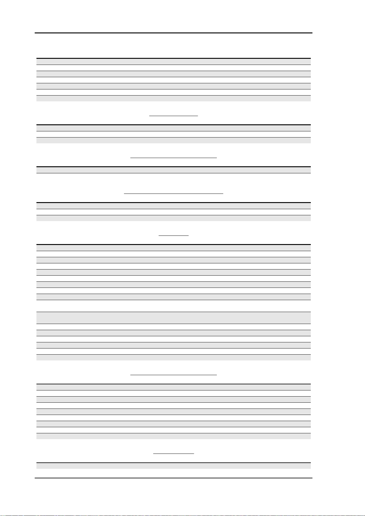
•
Take the left cylinder piston to TDC and
lock crankshaft rotation.
Specific tooling
020675Y Service shaft gear lock
•
Thoroughly clean the upper surface of
both cylinders.
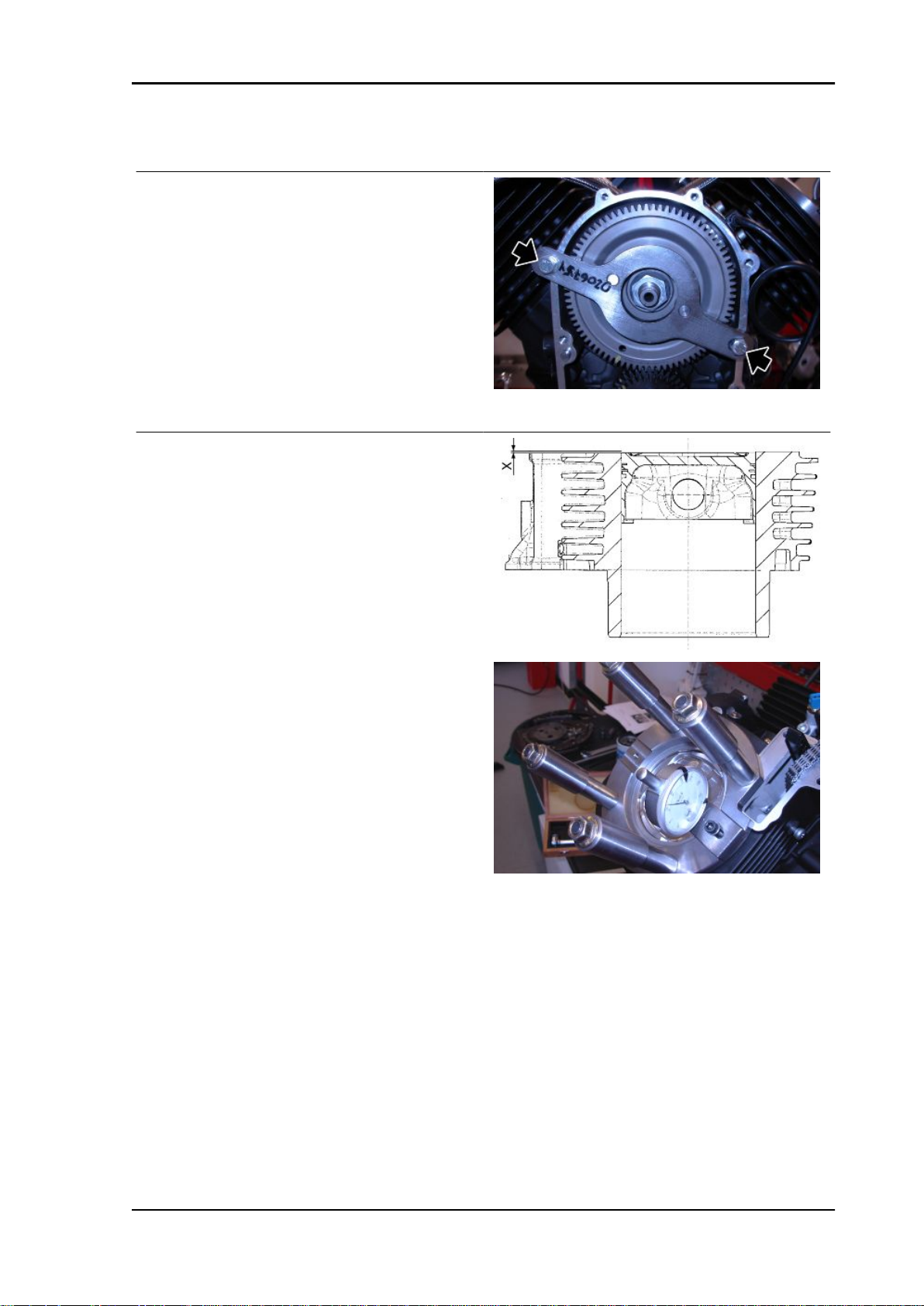
•
Place the tool on the left cylinder to de-
termine the "squish" (X).
•
Fasten the tool with the nuts of the stud
bolts.
Specific tooling
020676Y Comparator support for piston position checking
•
Reset the micrometer on the cylinder rim.
•
Move the tool so that the micrometer feeler reaches the top point of the piston crown.
•
Take note of the measurement and, according to the values found, consult the chart at the
bottom of the page to decide the thickness of the gasket to be fitted between cylinder and
head.
•
Unlock crankshaft rotation.
•
Rotate the crankshaft by 90°until the right cylinder piston reaches the TDC.
•
Lock crankshaft rotation.
•
Place the tool on the right cylinder stud bolts to determine the "squish" (X).
Specific tooling
020676Y Comparator support for piston position checking
CHAR - 21

Characteristics STELVIO 4V - 1200 ABS
Revente Interdite - Revendita Vietata - Resaling Forbiden - Wiederverkauf Verboten
•
Repeat the same operations to determine the thickness of the left cylinder gasket between
cylinder and head also for the right cylinder.
CYLINDER GASKET THICKNESS - HEAD
Specification Desc./Quantity
Value (X) -0.56 / -0.37 mm (-0.022 / -0.0146 in) gasket thickness: 0.65 mm (0.0256 in)
Value (X) -0.37 / -0.19 mm (-0.0146 / -0.0075 in) gasket thickness: 0.85 mm (0.0335 in)
Value (X) -0.19 / 0 mm (-0.0075 / 0 in) gasket thickness: 1.05 mm (0.0413 in)
Recommended products chart
RECOMMENDED PRODUCTS
Product Description Specifications
AGIP RACING 4T 10W-60 Engine oil SAE 10W - 60. As an alternative to the
AGIP GEAR SAE 80 W 90 Transmission oil -
AGIP GEAR MG/S SAE 85 W 90 Gearbox oil -
AGIP ARNICA SA 32 Fork oil SAE 0W - ISO VG 32
AGIP GREASE SM2 Lithium grease with molybdenum for
bearings and other points needing lubri-
cation
Neutral grease or petroleum jelly. BATTERY POLES
AGIP BRAKE 4 / BRAKE 5.1 Brake fluid As an alternative for recommended fluids
AGIP BRAKE 4 / BRAKE 5.1 Clutch fluid As an alternative for recommended fluids
suggested oils, one may use brand name
oils with performances matching or high-
er than CCMC G-<metricconverter pro-
ductid="4 A" w:st="on" />4 A</metricconverter />.P.I. SG specifications.
NLGI 2
use top-branded fluids that meet or ex-
ceed the requirements of SAE J1703,
NHTSA 116 DOT 4, ISO 4925 Synthetic
fluid specifications.
use top-branded fluids that meet or ex-
ceed the requirements of SAE J1703,
NHTSA 116 DOT 4, ISO 4925 Synthetic
fluid specifications.
CHAR - 22

INDEX OF TOPICS
Revente Interdite - Revendita Vietata - Resaling Forbiden - Wiederverkauf Verboten
SPECIAL TOOLS S-TOOLS
Special tools STELVIO 4V - 1200 ABS
Revente Interdite - Revendita Vietata - Resaling Forbiden - Wiederverkauf Verboten
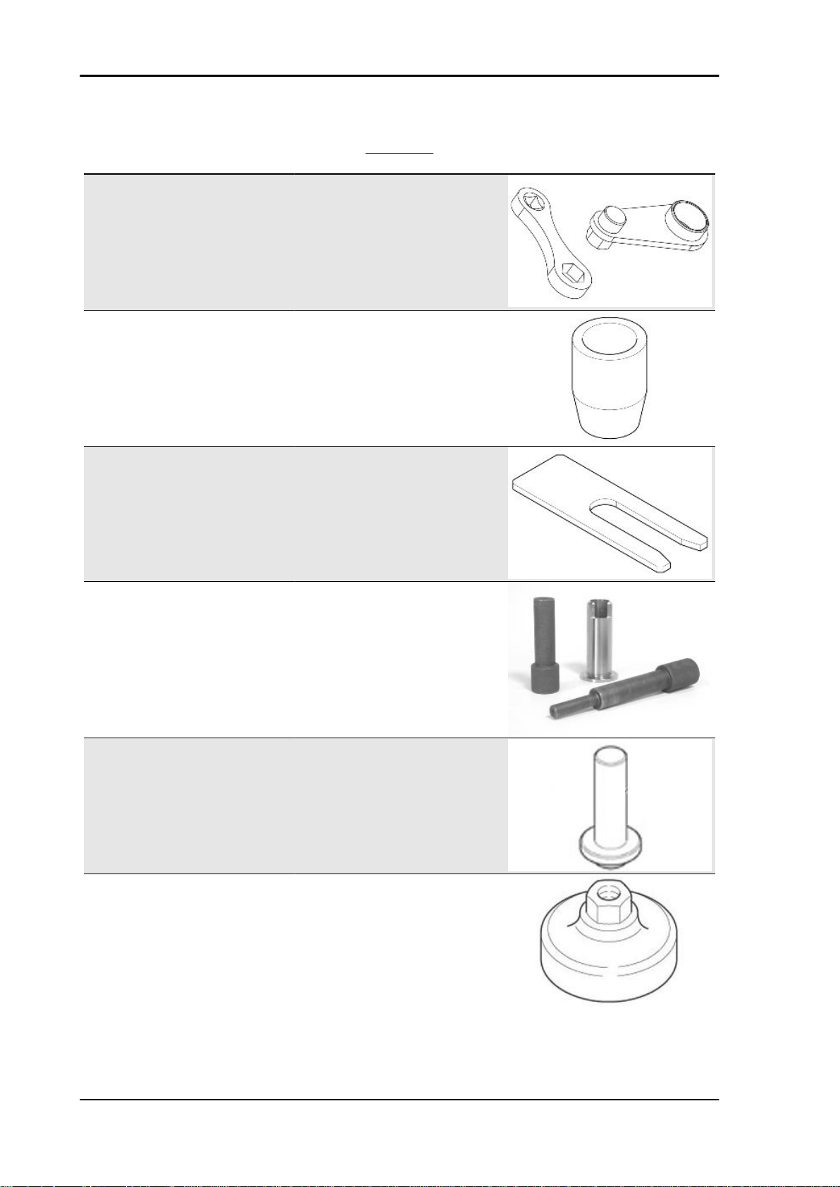
MOTORE
Stores code Description
020677Y Alternator belt tensioner, Belt tensioning
05.91.17.30 Front cover insertion cone
020716Y Connecting rod locking
lever
020470Y Pin snap ring fitting tool
05.92.72.30 Timing system cover sealing ring punch
01.92.91.00 Wrench for removing the cover on sump
and filter
S-TOOLS - 24
STELVIO 4V - 1200 ABS Special tools
Revente Interdite - Revendita Vietata - Resaling Forbiden - Wiederverkauf Verboten
Stores code Description
05.90.25.30 Gearbox support
19.92.96.00 Graduated dial to control ignition timing
12.91.18.01 Tool to lock the flywheel and the starting
12.91.36.00 Tool to remove the flywheel-side flange
AP8140179 Support for valve fitting/removal
AP9100838 Tool for valve pressure plate
ring gear
14.92.71.00 Tool to fit the sealing ring on the flywheelside flange
S-TOOLS - 25
Special tools STELVIO 4V - 1200 ABS
Revente Interdite - Revendita Vietata - Resaling Forbiden - Wiederverkauf Verboten
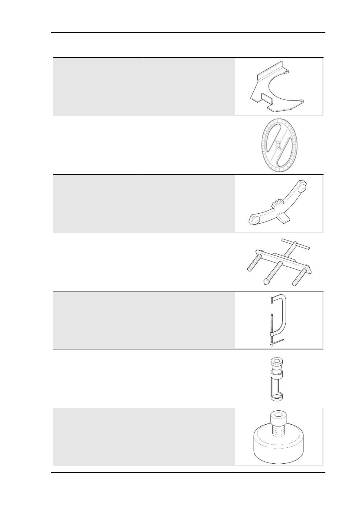
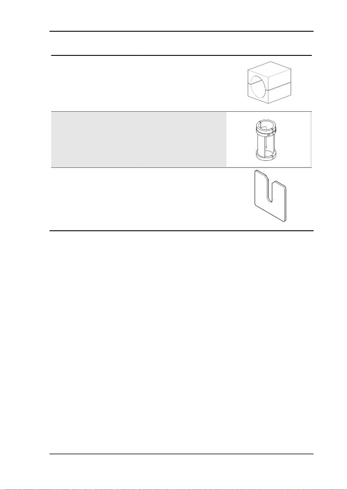
Stores code Description
12.91.20.00 Tool to fit the flywheel-side flange together with sealing ring on the crankshaft
19.92.71.00 Tool to fit the sealing ring on the flywheel-
020673Y Graduated dial hub
020672Y Clutch spring centre and pusher
020674Y Piston ring clamp
side flange
020675Y Service shaft gear lock
020676Y Comparator support for piston position
checking
S-TOOLS - 26
STELVIO 4V - 1200 ABS Special tools
Revente Interdite - Revendita Vietata - Resaling Forbiden - Wiederverkauf Verboten
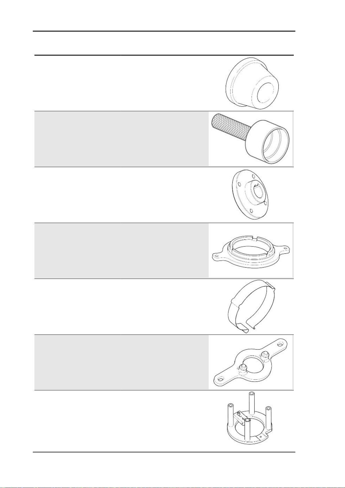
Stores code Description
020678Y Tool for clutch rod checking
05.91.25.30 Gearbox opening
CHASSIS
Stores code Description
14.91.26.03 Hook spanner for fixing ring nut of the
clutch shaft internal body
AP8140190 Tool for steering tightening
BEVEL GEAR SET
Stores code
05.90.27.30 Gearbox support
Description
S-TOOLS - 27
Special tools STELVIO 4V - 1200 ABS
Revente Interdite - Revendita Vietata - Resaling Forbiden - Wiederverkauf Verboten
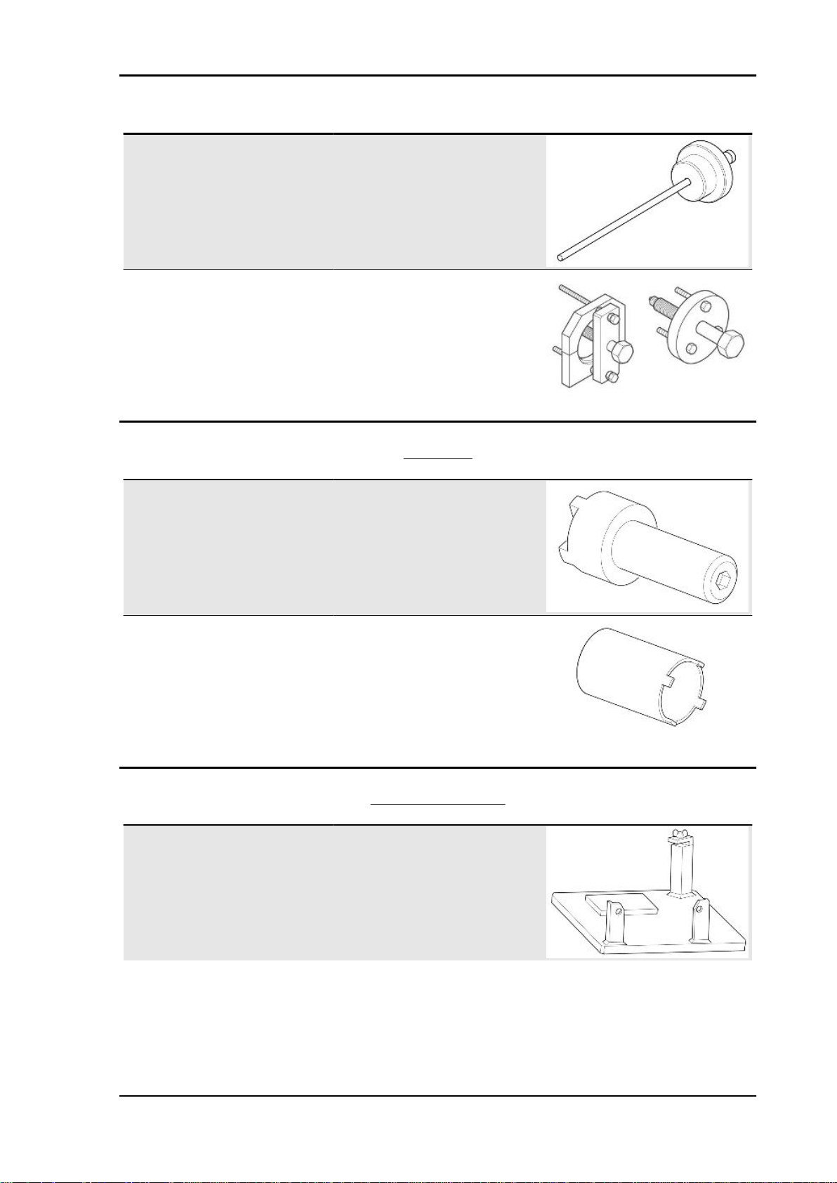
Stores code Description
05.90.27.31 Gearbox oil seal buffer
05.90.27.32 Buffer handgrip
05.90.27.33 Ball joint sealing buffer
05.90.27.34 Wrench for pinion ring nut
05.90.27.35 Pinion oil seal buffer
FRONT FORK
Stores code
AP8140146 Weight
Description
S-TOOLS - 28
STELVIO 4V - 1200 ABS Special tools
Revente Interdite - Revendita Vietata - Resaling Forbiden - Wiederverkauf Verboten
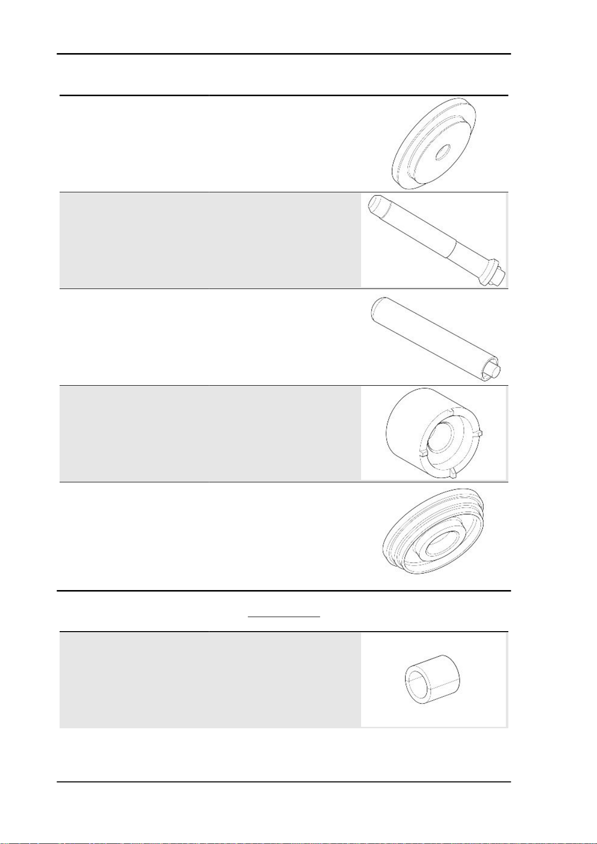
Stores code Description
AP8140149 Protection for fitting operations
9100903 Marzocchi fork oil seal; ø 45 mm (1.77 in)
020886Y Spacer / pumping member pin splitting
plate
S-TOOLS - 29

INDEX OF TOPICS
Revente Interdite - Revendita Vietata - Resaling Forbiden - Wiederverkauf Verboten
MAINTENANCE MAIN
 Loading...