

SERVICE STATION MANUAL
B043090
Stelvio 1200 NTX MY11

SERVICE STATION
Revente Interdite - Revendita Vietata - Resaling Forbiden - Wiederverkauf Verboten
MANUAL
Stelvio 1200 NTX MY11
THE VALUE OF SERVICE
Only the mechanics of the Official Moto Guzzi Service Network know this vehicle well, thanks to constant
technical professional development and Moto Guzzi specific training programmes, and have the tools
needed to carry out maintenance and repair operations correctly.
The reliability of the vehicle also depends on its mechanical conditions. Checking the vehicle before riding
it, carrying out routine maintenance and using only Moto Guzzi Original Spare parts is fundamental!
For information about the nearest Official Dealer and/or Service Centre, consult the Yellow Pages or
search directly on the inset map in our Official Website:
www.motoguzzi.it
Only by purchasing Moto Guzzi Original Spare Parts will you get a product designed and tested during
the bike designing phase. Moto Guzzi Original Spare Parts are subject to systematic quality control
procedures so that their reliability and performance over time is guaranteed.
The descriptions and illustrations given in this publication are not binding; While the basic features as
described and illustrated in this booklet remain unchanged, Moto Guzzi reserves the right, at any time
and without being required to update this publication beforehand, to make any changes to components,
parts or accessory supplies, which it deems necessary to improve the product or which are required for
manufacturing or commercial reasons.
Not all versions/models shown in this publication are available in all countries. The availability of individual
versions should be checked with the Official Moto Guzzi sales network.
© Copyright 2011- Moto Guzzi. All rights reserved. Reproduction of this publication in whole or in part is
prohibited. Moto Guzzi - After sales service.
The Moto Guzzi brand is owned by Piaggio & C. S.p.A.
SERVICE STATION MANUAL
Revente Interdite - Revendita Vietata - Resaling Forbiden - Wiederverkauf Verboten
Stelvio 1200 NTX MY11
This manual provides the main information to carry out regular maintenance operations on your scooter.
This manual is intended to Moto Guzzi Dealers and their qualified mechanics; several concepts have
been deliberately omitted as they are considered unnecessary. As it is not possible to include complete
mechanical notions in this manual, users should have basic mechanical knowledge or minimum
knowledge about the procedures involved when repairing scooters. Without this knowledge, repairing or
checking the vehicle may be inefficient or even dangerous. As the vehicle repair and check procedures
are not described in detail, be extremely cautious so as not to damage components or injure individuals.
In order to optimise customer satisfaction when using our vehicles, Moto Guzzi s.p.a. commits itself to
continually improve its products and the relative documentation. The main technical modifications and
changes in repair procedures are communicated to all Moto Guzzi Sales Outlets and its International
Subsidiaries. These changes will be introduced in the subsequent editions of the manual. In case of
need or further queries on repair and check procedures, consult Moto Guzzi CUSTOMER
DEPARTMENT, which will be prepared to provide any information on the subject and any further
communications on updates and technical changes related to the vehicle.
2011
NOTE Provides key information to make the procedure easier to understand and carry out.
CAUTION Refers to specific procedures to carry out for preventing damages to the vehicle.
WARNING Refers to specific procedures to carry out to prevent injuries to the repairer.
Personal safety Failure to completely observe these instructions will result in serious risk of personal
injury.
Safeguarding the environment Sections marked with this symbol indicate the correct use of the vehicle
to prevent damaging the environment.
Vehicle intactness The incomplete or non-observance of these regulations leads to the risk of serious
damage to the vehicle and sometimes even the invalidity of the guarantee.
Revente Interdite - Revendita Vietata - Resaling Forbiden - Wiederverkauf Verboten
INDEX OF TOPICS
Revente Interdite - Revendita Vietata - Resaling Forbiden - Wiederverkauf Verboten
CHARACTERISTICS CHAR
SPECIAL TOOLS S-TOOLS
MAINTENANCE MAIN
ELECTRICAL SYSTEM ELE SYS
ENGINE FROM VEHICLE ENG VE
ENGINE ENG
POWER SUPPLY P SUPP
SUSPENSIONS SUSP
CHASSIS CHAS
BRAKING SYSTEM BRAK SYS
BODYWORK BODYW
PRE-DELIVERY PRE DE

INDEX OF TOPICS
Revente Interdite - Revendita Vietata - Resaling Forbiden - Wiederverkauf Verboten
CHARACTERISTICS CHAR
Stelvio 1200 NTX MY11 Characteristics
Revente Interdite - Revendita Vietata - Resaling Forbiden - Wiederverkauf Verboten
Rules
Safety rules
Carbon monoxide
If you need to keep the engine running while working on the vehicle, please ensure that you do so in
an open or very well ventilated area. Never let the engine run in an enclosed area. If you do work in an
enclosed area, make sure to use a fume extraction system.
CAUTION
EXHAUST EMISSIONS CONTAIN CARBON MONOXIDE, A POISONOUS GAS WHICH CAN CAUSE
LOSS OF CONSCIOUSNESS AND EVEN DEATH.
Fuel
CAUTION
THE FUEL USED TO POWER INTERNAL COMBUSTION ENGINES IS HIGHLY FLAMMABLE AND
MAY BE EXPLOSIVE UNDER CERTAIN CONDITIONS. IT IS THEREFORE RECOMMENDED TO
CARRY OUT REFUELLING AND MAINTENANCE PROCEDURES IN A VENTILATED AREA WITH
THE ENGINE SWITCHED OFF. DO NOT SMOKE DURING REFUELLING OR NEAR FUEL VAPOUR.
AVOID ANY CONTACT WITH NAKED FLAME, SPARKS OR OTHER HEAT SOURCES WHICH MAY
CAUSE IGNITION OR EXPLOSION.
DO NOT ALLOW FUEL TO DISPERSE INTO THE ENVIRONMENT.
KEEP OUT OF THE REACH OF CHILDREN.
Hot components
The engine and the exhaust system components become very hot and remain hot for some time after
the engine has been switched off. Before handling these components, make sure that you are wearing
insulating gloves or wait until the engine and the exhaust system have cooled down.
Used engine oil and transmission oil
CAUTION
IT IS ADVISABLE TO WEAR LATEX GLOVES WHEN SERVICING THE VEHICLE.
THE ENGINE OR GEARBOX OIL MAY CAUSE SERIOUS INJURIES TO THE SKIN IF HANDLED
FOR PROLONGED PERIODS OF TIME AND ON A REGULAR BASIS.
WASH YOUR HANDS CAREFULLY AFTER HANDLING OIL.
HAND THE OIL OVER TO OR HAVE IT COLLECTED BY THE NEAREST USED OIL RECYCLING
COMPANY OR THE SUPPLIER.
DO NOT DISPOSE OF OIL IN THE ENVIRONMENT
KEEP OUT OF THE REACH OF CHILDREN.
Brake and clutch fluid
CHAR - 7
Characteristics Stelvio 1200 NTX MY11
Revente Interdite - Revendita Vietata - Resaling Forbiden - Wiederverkauf Verboten
BRAKE AND CLUTCH FLUIDS CAN DAMAGE THE PLASTIC OR RUBBER PAINTED SURFACES.
WHEN SERVICING THE BRAKING OR THE CLUTCH SYSTEM PROTECT THESE COMPONENTS
WITH A CLEAN CLOTH. ALWAYS WEAR PROTECTIVE GOGGLES WHEN SERVICING THESE
SYSTEMS. BRAKE AND CLUTCH FLUIDS ARE EXTREMELY HARMFUL FOR YOUR EYES. IN
THE EVENT OF ACCIDENTAL CONTACT WITH THE EYES, RINSE THEM IMMEDIATELY WITH
PLENTY OF COLD, CLEAN WATER AND SEEK MEDICAL ADVICE.
KEEP OUT OF THE REACH OF CHILDREN.
Battery electrolyte and hydrogen gas
CAUTION
THE BATTERY ELECTROLYTE IS TOXIC, CORROSIVE AND, AS IT CONTAINS SULPHURIC
ACID, MAY CAUSE BURNING IF IT COMES INTO CONTACT WITH THE SKIN. WHEN HANDLING
BATTERY ELECTROLYTE, WEAR TIGHT-FITTING GLOVES AND PROTECTIVE APPAREL. IN
THE EVENT OF SKIN CONTACT WITH THE ELECTROLYTIC FLUID, RINSE WELL WITH PLENTY
OF CLEAN WATER. IT IS PARTICULARLY IMPORTANT TO PROTECT YOUR EYES BECAUSE
EVEN TINY AMOUNTS OF BATTERY ACID MAY CAUSE BLINDNESS. IN THE EVENT OF CON-
TACT WITH THE EYES, RINSE WITH PLENTY OF WATER FOR FIFTEEN MINUTES AND CON-
SULT AN EYE SPECIALIST IMMEDIATELY. IF THE FLUID IS ACCIDENTALLY SWALLOWED,
DRINK LARGE QUANTITIES OF WATER OR MILK, FOLLOWED BY MILK OF MAGNESIA OR
VEGETABLE OIL AND SEEK MEDICAL ADVICE IMMEDIATELY. THE BATTERY RELEASES EX-
PLOSIVE GASES; KEEP IT AWAY FROM FLAMES, SPARKS, CIGARETTES OR ANY OTHER
HEAT SOURCES. ENSURE ADEQUATE VENTILATION WHEN SERVICING OR RECHARGING
THE BATTERY.
KEEP OUT OF THE REACH OF CHILDREN.
BATTERY LIQUID IS CORROSIVE. DO NOT POUR IT OR SPILL IT, PARTICULARLY ON PLASTIC
COMPONENTS. ENSURE THAT THE ELECTROLYTIC ACID IS COMPATIBLE WITH THE BAT-
TERY BEING ACTIVATED.
Maintenance rules
GENERAL PRECAUTIONS AND INFORMATION
When repairing, dismantling and reassembling the vehicle, follow the recommendations given below
carefully.
BEFORE DISASSEMBLING COMPONENTS
•
Before dismantling components, remove dirt, mud, dust and foreign bodies from the vehicle.
Use the special tools designed for this bike, as required.
COMPONENTS REMOVAL
•
Do not loosen and/or tighten screws and nuts using pliers or any other tools than the specific
wrench.
•
Mark the positions on all connection joints (pipes, cables, etc.) before separating them, and
identify them with different distinctive symbols.
•
Each component needs to be clearly marked to enable identification during reassembly.
•
Clean and wash the dismantled components carefully using a low-flammability detergent.
CHAR - 8

Stelvio 1200 NTX MY11 Characteristics
Revente Interdite - Revendita Vietata - Resaling Forbiden - Wiederverkauf Verboten
•
Keep mated parts together since they have "adjusted" to each other due to normal wear.
•
Some components must be used together or replaced altogether.
•
Keep away from heat sources.
REASSEMBLING COMPONENTS
CAUTION
BEARINGS MUST ROTATE FREELY, WITHOUT JAMMING AND/OR NOISE, OTHERWISE, THEY
NEED TO BE REPLACED.
•
Only use ORIGINAL Moto Guzzi SPARE PARTS.
•
Comply with lubricant and consumables use guidelines.
•
Lubricate parts (whenever possible) before reassembling them.
•
When tightening nuts and screws, start from the ones with the largest section or from the
internal ones, moving diagonally. Tighten nuts and screws in successive steps before applying the tightening torque.
•
Always replace self-locking nuts, washers, sealing rings, circlips, O-rings (OR), split pins
and screws with new ones if their tread is damaged.
•
When assembling the bearings, make sure to lubricate them well.
•
Check that each component is assembled correctly.
•
After a repair or routine maintenance procedure, carry out pre-ride checks and test the vehicle on private grounds or in an area with low traffic density.
•
Clean all coupling surfaces, oil guard rims and gaskets before refitting them. Smear a light
layer of lithium-based grease on the oil guard rims. Reassemble oil guards and bearings
with the brand or lot number facing outward (visible side).
ELECTRIC CONNECTORS
Electric connectors must be disconnected as described below; failure to comply with this procedure
causes irreparable damage to both the connector and the wiring harness:
Press the relative safety clips, if applicable.
•
Grip the two connectors and disconnect them by pulling them in opposite directions.
•
If any signs of dirt, rust, moisture, etc. are noted, clean the inside of the connector carefully
with a jet of compressed air.
•
Ensure that the cables are correctly fastened to the internal connector terminals.
•
Then connect the two connectors, ensuring that they couple correctly (if fitted with clips, you
will hear them "click" into place).
CAUTION
DO NOT DISCONNECT CONNECTORS BY PULLING THE CABLES.
NOTE
THE TWO CONNECTORS CAN ONLY BE CONNECTED IN ONE DIRECTION: CONNECT THEM
THE RIGHT WAY ROUND.
TIGHTENING TORQUES
CAUTION
REMEMBER THAT THE TIGHTENING TORQUES FOR ALL FASTENING ELEMENTS ON WHEELS,
BRAKES, WHEEL AXLES AND ANY OTHER SUSPENSION COMPONENTS PLAY A KEY ROLE
CHAR - 9
Characteristics Stelvio 1200 NTX MY11
Revente Interdite - Revendita Vietata - Resaling Forbiden - Wiederverkauf Verboten
IN ENSURING VEHICLE SAFETY AND MUST COMPLY WITH SPECIFIED VALUES. CHECK THE
TIGHTENING TORQUES OF FASTENING ELEMENTS ON A REGULAR BASIS AND ALWAYS USE
A TORQUE WRENCH TO REASSEMBLE THESE COMPONENTS. FAILURE TO COMPLY WITH
THESE RECOMMENDATIONS MAY CAUSE ONE OF THESE COMPONENTS TO LOOSEN OR
EVEN DETACH, CAUSING A WHEEL TO LOCK OR COMPROMISING VEHICLE HANDLING. THIS
MAY LEAD TO FALLS, WITH THE RISK OF SERIOUS INJURY OR DEATH.
Running-in
Engine run-in is essential to ensure engine long life and correct operation. Twisty roads and gradients
are ideal to run in engine, brakes and suspensions effectively. Vary your riding speed during the run-
in. This ensures that components operate under both "loaded" and "unloaded" conditions, allowing the
engine components to cool.
CAUTION
THE CLUTCH MAY EMIT A SLIGHT BURNING SMELL WHEN FIRST USED. THIS PHENOMENON
SHOULD BE CONSIDERED NORMAL AND WILL DISAPPEAR AS SOON AS THE CLUTCH DISCS
GET ADAPTED.
IT IS IMPORTANT TO STRAIN ENGINE COMPONENTS DURING RUN-IN, HOWEVER, MAKE SURE
NOT TO OVERDO THIS.
CAUTION
THE FULL PERFORMANCE OF THE VEHICLE IS ONLY AVAILABLE AFTER THE SERVICE AT
THE END OF THE RUNNING IN PERIOD.
Follow the guidelines detailed below:
•
Do not twist the throttle grip abruptly and completely when the engine is working at a low
revs, either during or after run-in.
•
During the first 100 Km (62 miles) use the brakes gently, avoiding sudden or prolonged
braking. That is to permit the adequate adjustment of the pad friction material to the brake
discs.
AFTER THE SPECIFIED MILEAGE, TAKE THE VEHICLE TO AN OFFICIAL Moto Guzzi DEALER
FOR THE CHECKS INDICATED IN THE "AFTER RUN-IN" TABLE IN THE SCHEDULED MAINTE-
NANCE SECTION TO AVOID INJURING YOURSELF, OTHERS AND /OR DAMAGING THE VEHI-
CLE.
Vehicle identification
SERIAL NUMBER LOCATION
These numbers are necessary for vehicle registration.
NOTE
ALTERING IDENTIFICATION NUMBERS MAY BE SERIOUSLY PUNISHABLE BY LAW. IN PAR-
TICULAR, MODIFYING THE CHASSIS NUMBER IMMEDIATELY VOIDS THE WARRANTY.
CHAR - 10

Stelvio 1200 NTX MY11 Characteristics
Revente Interdite - Revendita Vietata - Resaling Forbiden - Wiederverkauf Verboten
This number consists of numbers and letters, as in
the example shown below.
ZGULZG000YMXXXXXX
KEY:
ZGU: WMI (World manufacturer identifier) code;
LZ: model;
001: version variation;
0: free digit
Y year of manufacture
M: production plant (M= Mandello del Lario);
XXXXXX: serial number (6 digits);
CHASSIS NUMBER
The chassis number is stamped on the right hand
side of the headstock.
ENGINE NUMBER
The engine number is stamped on the left side,
close to the engine oil level check cap.
Dimensions and mass
WEIGHT AND DIMENSIONS
Specification
Maximum length (without accessories) 2,305 mm (90.75 in)
Maximum width to handlebar 956 mm (37.64 in)
Maximum width of the vehicle with accessories 1,080 mm (42.52 in)
Minimum / maximum height (adjustable windshield) 1436 / 1492 mm (56.53 / 58.74 in)
Saddle height 800 mm (31.5 in)
Minimum ground clearance 185 mm (7.3 in)
Wheelbase 1,535 mm (60.43 in)
Kerb weight 281 kg (619.50 lb)
Kerb weight of full house vehicle 296 kg (652.57 lb)
Desc./Quantity
Engine
ENGINE
Specification
Type traverse-mounted twin-cylinder four-stroke V 90°
Number of cylinders 2
Cylinder layout 90° V
Desc./Quantity
CHAR - 11
Characteristics Stelvio 1200 NTX MY11
Revente Interdite - Revendita Vietata - Resaling Forbiden - Wiederverkauf Verboten
Specification Desc./Quantity
Bore / stroke 95 x 81.2 mm (3.74 x 3.20 in)
Engine capacity 1151 cm³ (70 cu.in.)
Compression ratio 11 : 1
Ignition starter
Engine idle speed 1100 ± 100 rpm
Clutch hydraulically controlled single-plate dry clutch with incorpora-
Lubrication system Pressurised circuit with regulator valves and trochoidal pump
Air filter cartridge-type dry filter
Cooling air and oil cooled with independent trochoidal pump and oil
pressure control valve
Timing system diagram single overhead camshaft with bucket tappets and rocker-op-
Values valid with control clearance between rocker and valve intake: 0.15 mm (0.0059 in)
ted flexible coupling
erated valves
outlet: 0.20 mm (0.0079 in)
Transmission
TRANSMISSION
Specification Desc./Quantity
Primary drive Helical gears, ratio 26/35 = 1:1.346
Gearbox Mechanical, 6 speeds with foot lever on the left hand side of
Gear ratios, 1st gear 17/38 = 1:2.2353
Gear ratios, 2nd gear 20/34 = 1:1.7
Gear ratios, 3rd gear 23/31 = 1:1.3478
Gear ratios, 4th gear 26/29 = 1:1.1154
Gear ratios, 5th gear 31/30 = 1:0.9677
Gear ratios, 6th gear 29/25 = 1:0.8621
Final drive with U-joint
Ratio 12/44 = 1:3.6667
the engine
Capacities
Specification
Engine oil Oil change and oil filter replacement: 3,500 cm³ (214 cu.in)
Gearbox oil 500 cm³ (30.5 cu in)
Transmission oil 380 cm³ (23.2 cu in)
Fuel (reserve included) 32 l (7.04 UK gal)
Fuel reserve 7 l (1.54 UK gal)
Maximum weight limit 495 kg (1091.29 lb)
Electrical system
Specification
Spark plug NGK CR8EKB (long life)
Electrode gap 0.6 - 0.7 mm (0.024 - 0.028 in)
Alternator (permanent magnet type) 12 V - 550 W
Main fuses 20 (ABS version only) - 30 (2) - 40 A
Secondary fuses 3 - 10 - 15A
Front daylight running light 12V - 5W
Low/high beam light (halogen) 12 V - 55 W / 60 W H4
Turn indicators 12V - 10 W
CAPACITIES
Desc./Quantity
Fork oil 650 cm³ (39.66 cu.in) (for each stem)
Seats 2
ELECTRICAL SYSTEM
Desc./Quantity
Battery 12 V - 18 Ampere/hour
CHAR - 12
Stelvio 1200 NTX MY11 Characteristics
Revente Interdite - Revendita Vietata - Resaling Forbiden - Wiederverkauf Verboten
Specification Desc./Quantity
Rear daylight running light/stop light LED
Supplementary headlamps (if fitted) 12 V/55W - H3
Dashboard lighting LED
License plate light 12V - 5 W
Turn indicator warning light LED
Neutral gear warning light LED
Alarm-shift warning light LED
Side stand down warning light LED
Low fuel warning light LED
High beam warning light LED
ABS warning light LED
Frame and suspensions
CHASSIS
Specification Desc./Quantity
Type high strength tubular steel frame with engine as stressed ele-
Trail 125 mm (4.92 in)
Headstock angle 27°
Front Upside down telescopic hydraulic fork, with 45mm (1.77 in) di-
am., stanchions and radial calliper mounting bracket with ad-
justable spring preload and hydraulic compression and re-
Front wheel travel 170 mm (6.69 in)
Rear single arm with progressive linkage, single shock absorber with
spring preload, hydraulic compression and rebound damping
Unloaded shock absorber spring length 180 mm (7.09 in)
Rear wheel travel 155 mm (6.10 in)
ment
bound damping.
adjustment.
Brakes
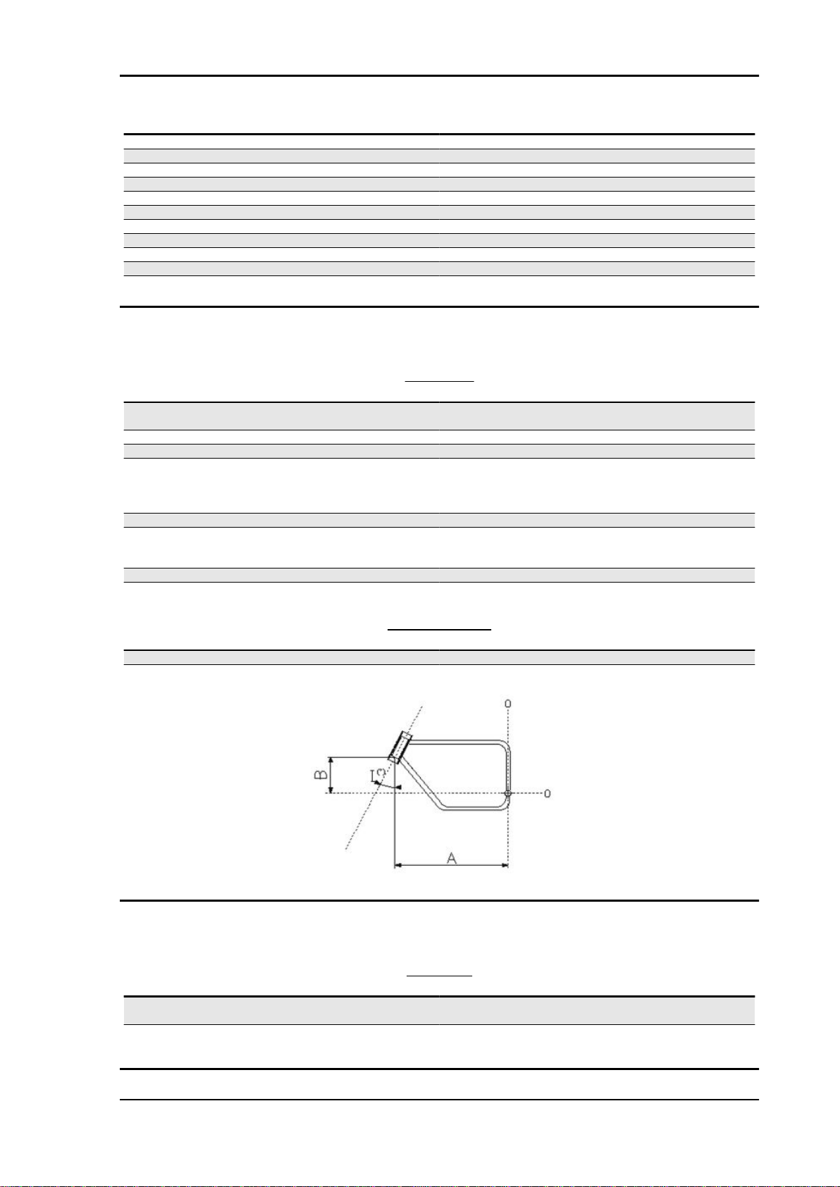
SIZES A AND B
Specification
Size A 745.0 mm (29.33 in)
Size B 403.16 mm (15.87 in)
Desc./Quantity
BRAKES
Specification
Front Ø 320-mm (12.6 in) stainless steel double floating disc, radial
Rear Ø 282-mm (11.1 in) stainless steel disc, floating calliper with 2
Desc./Quantity
callipers with 4 opposed pistons.
different pins
CHAR - 13
Characteristics Stelvio 1200 NTX MY11
Revente Interdite - Revendita Vietata - Resaling Forbiden - Wiederverkauf Verboten
Wheels and tyres
WHEELS AND TYRES
Wheel Model Wheel rim Measure
Front (standard) H SPECIFIC Pirelli
Scorpion Trail
Rear (standard) H SPECIFIC Pirelli
Scorpion Trail
2.50 x 19" 110/80
4.25 x 17" 150/70
ment
R19 - 59V
R17 - 69V
THE USE OF M+S TYRES IS ALLOWED ONLY ON VEHICLES WITHOUT THE ABS SYSTEM.
WITH THIS TYRE TYPE, THE MAXIMUM SPEED ALLOWED IS 170 km/h (105.63 mi)
IT IS MANDATORY TO APPLY THE LABEL ONTO THE SPEEDOMETER (SUPPLIED WITH THE
TYRES) INDICATING THE MAXIMUM SPEED, WHEN FITTING M + S TYRES. WITH "OFF-ROAD /
ALLROUND" TYRES, PAY CLOSE ATTENTION WHEN DRIVING ON PAVED ROAD DUE TO ITS
LACK OF GRIP AND STABILITY.
Tyre pressure with
rider only
2.5 bar (250 kPa) (36.3
PSI)
2.9 bar (290 kPa) (42.1
PSI)
Tyre pressure, rider +
passenger
2.5 bar (250 kPa) (36.3
PSI)
2.9 bar (290 kPa) (42.1
PSI)
Supply
Specification
Fuel system Electronic injection (Weber . Marelli) with stepper motor
Diffuser diameter: 50 mm (1.97 in)
Fuel Premium unleaded petrol, minimum octane rating 95 (NORM)
Tightening Torques
FUEL SYSTEM
Desc./Quantity
and 85 (NOMM)
CHAR - 14
Stelvio 1200 NTX MY11 Characteristics
Revente Interdite - Revendita Vietata - Resaling Forbiden - Wiederverkauf Verboten
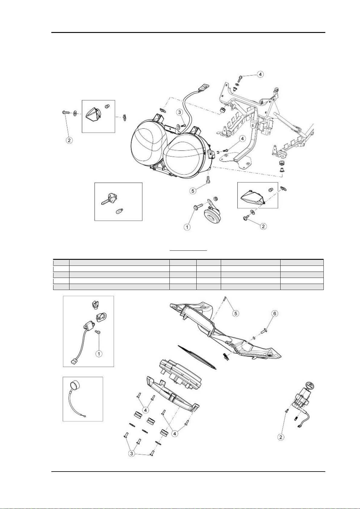
Front side
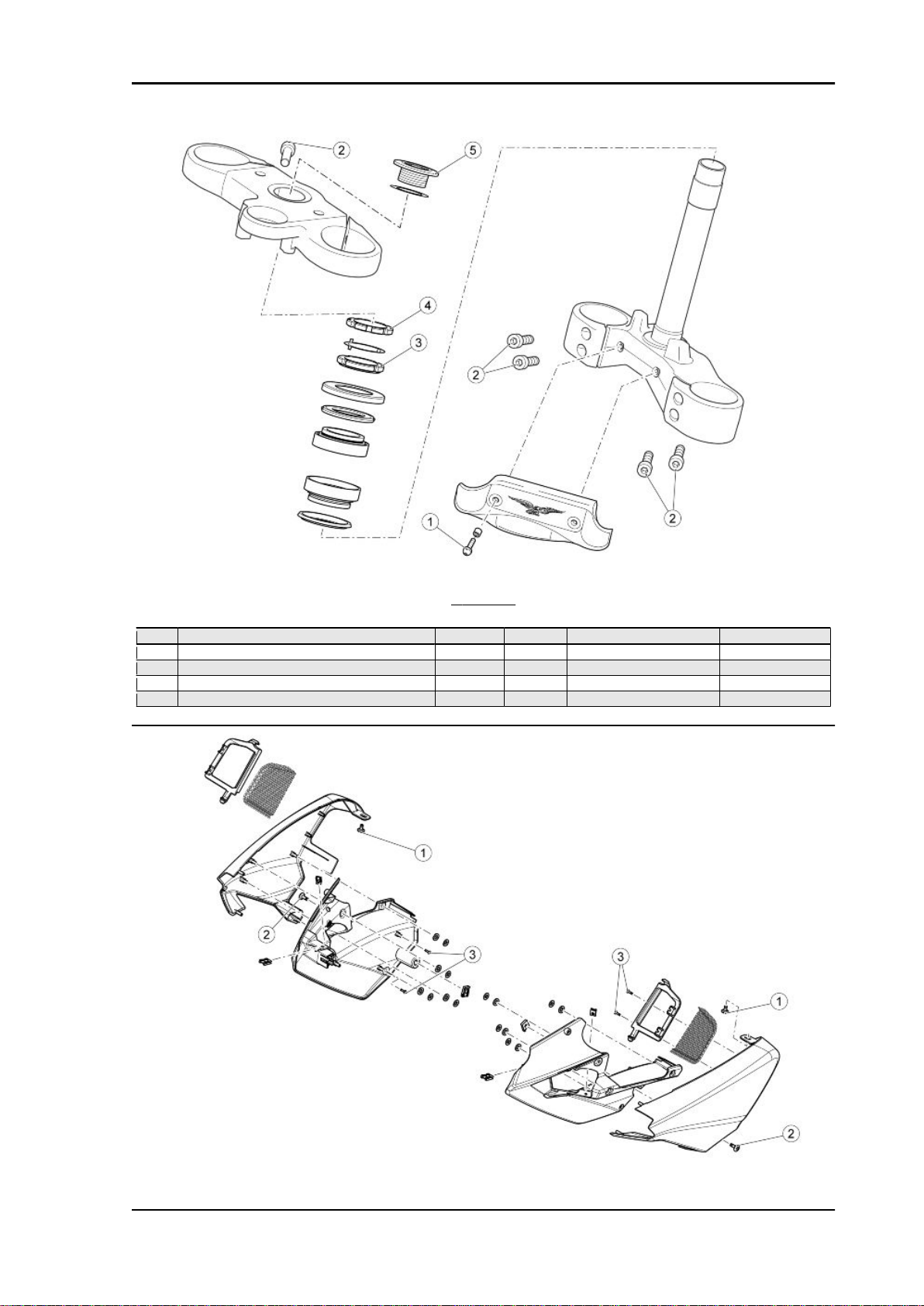
FRONT LIGHTS
pos.
1 Horn fixing screw M6x20 1 15 Nm (11.06 lbf ft) 2 Viti fissaggio freccie anteriori M4 2 3 Nm (2.21 lbf ft) 3 Vite fissaggio superiore fanale a carozzeria M4 1 3 Nm (2.21 lbf ft) 4 Viti fissaggio fanale a carozzeria M4x25 2 3 Nm (2.21 lbf ft) 5 Viti TCEI fissaggio fanale a telaietto M5x25 5 6 Nm (4.42 lbf ft) -
Description Type Quantity Torque Notes
CHAR - 15
Characteristics Stelvio 1200 NTX MY11
Revente Interdite - Revendita Vietata - Resaling Forbiden - Wiederverkauf Verboten
INSTRUMENT PANEL
pos. Description Type Quantity Torque Notes
1 Viti TCEI fissaggio sensore velocità anteriore M5x16 2 6 Nm (4.42 lbf ft) 2 Viti TCEI fissaggio blocchetto avviamento M8x30 1 25 Nm (18.44 lbf ft) 3 Viti autofil. fissaggio supporto cruscotto 5x14 3 Manual 4 Viti autofil. fissaggio supporto cruscotto a cor-
nice
5 Viti autofil. fissaggio cornice - 4 Manual 6 Viti TCE M5 2 6 Nm (4.42 lbf ft) -
3.9x14 4 Manual -
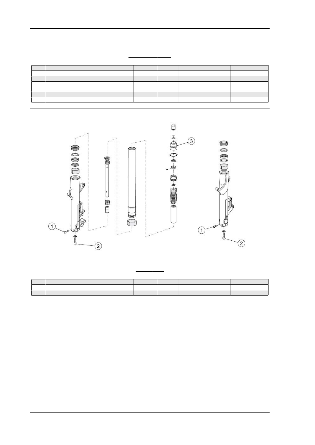
FRONT FORK
pos.
1 Viti piede forcella M8 1+1 25 Nm (18.44 lbf ft) 2 Viti chiusura mozzetti M6x30 2+2 10 Nm (7.38 lbf ft) 3 Fork cap - 1+1 - Nm (-.- lbf ft) -
CHAR - 16
Description Type Quantity Torque Notes
Stelvio 1200 NTX MY11 Characteristics
Revente Interdite - Revendita Vietata - Resaling Forbiden - Wiederverkauf Verboten
STEERING
pos.
1 Viti fissaggio piastra fermatubi - 2 6 Nm (4.42 lbf ft) 2 Viti fissaggio piastre M8x30 6 20 Nm (14.75 lbf ft) 3 Headstock ring nut - 1 40 Nm (29.50 lbf ft) 4 Headstock counter-lock ring - 1 manual + 90 degrees 5 Upper yoke fixing cap - 1 100 Nm (73.76 lbf ft) -
Description Type Quantity Torque Notes
CHAR - 17
Characteristics Stelvio 1200 NTX MY11
Revente Interdite - Revendita Vietata - Resaling Forbiden - Wiederverkauf Verboten
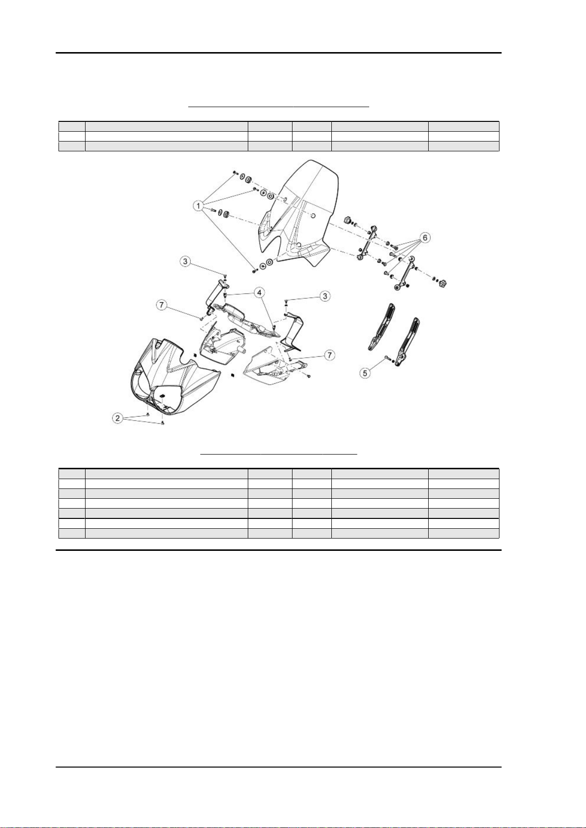
CARROZZERIA ANTERIORE - CONVOGLIATORI
pos. Description Type Quantity Torque Notes
1 Viti TBEI Flang. fissaggio convogliatori M5x9 2 6 Nm (4.42 lbf ft) 2 Viti TBEI Flang. fissaggio convogliatori M5 2 6 Nm (4.42 lbf ft) 3 Viti SWP Autofil. fissaggio telaietto griglie 2.9x12 4 Manual -
CARROZZERIA ANTERIORE - CUPOLINO
pos.
1 Viti fissaggio parabrezza M6 4 10 Nm (7.38 lbf ft) 2 Viti TBEI Flang. fissaggio cupolino M5x12 4 6 Nm (4.42 lbf ft) 3 Viti fissaggio deflettori superiori M5 4 6 Nm (4.42 lbf ft) 4 Colonnette fissaggio deflettori M5 2 6 Nm (4.42 lbf ft) 5 Viti TE Flang. fissaggio staffa parabrezza M6x16 4 10 Nm (7.38 lbf ft) 6 Perno filettato fissaggio supporto parabrezza M8 2 25 Nm (18.44 lbf ft) 7 Viti TBEI Flang. fissaggio deflettori inferiori M5 2 Manual -
Description Type Quantity Torque Notes
CHAR - 18
Stelvio 1200 NTX MY11 Characteristics
Revente Interdite - Revendita Vietata - Resaling Forbiden - Wiederverkauf Verboten
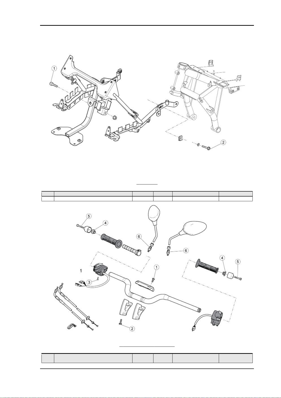
TELAIETTO
pos.
1 Viti TCEI fissaggio telaietto M8x40 2 25 Nm (18.44 lbf ft) 2 Viti TE Flang. M6x20 2 10 Nm (7.38 lbf ft) -
Description Type Quantity Torque Notes
HANDLEBAR AND CONTROLS
pos.
1 Viti TCC fissaggio cavallotti superiori manu-
Description Type Quantity Torque Notes
M8x30 4 25 Nm (18.44 lbf ft) -
brio
CHAR - 19
Characteristics Stelvio 1200 NTX MY11
Revente Interdite - Revendita Vietata - Resaling Forbiden - Wiederverkauf Verboten
pos. Description Type Quantity Torque Notes
2 Viti TE Flangiate fissaggio cavallotti inf. man-
ubrio
3 Vite autof. - 1 1.5 Nm (1.11 lbf ft) 4 Raccordo fissaggio pesi antivibranti M18x15 2 - Nm (-.-- lbf ft) 5 Viti TCEI fissaggio pesi antivibranti - 2 10 Nm (7.38 lbf ft) Loct. 243
6 Raccordi fissaggio specchi retrovisori M10 2 30 Nm (22.13 lbf ft) -
- 2 50 Nm (36.88 lbf ft) -
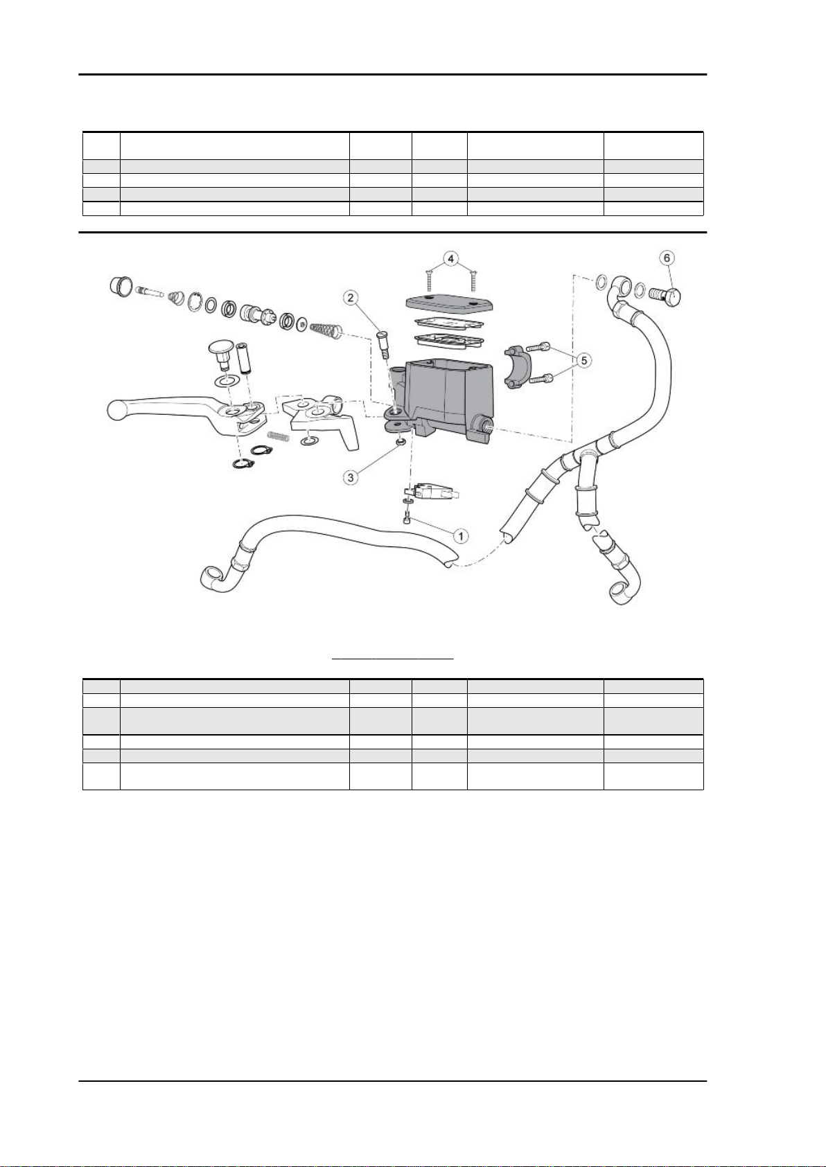
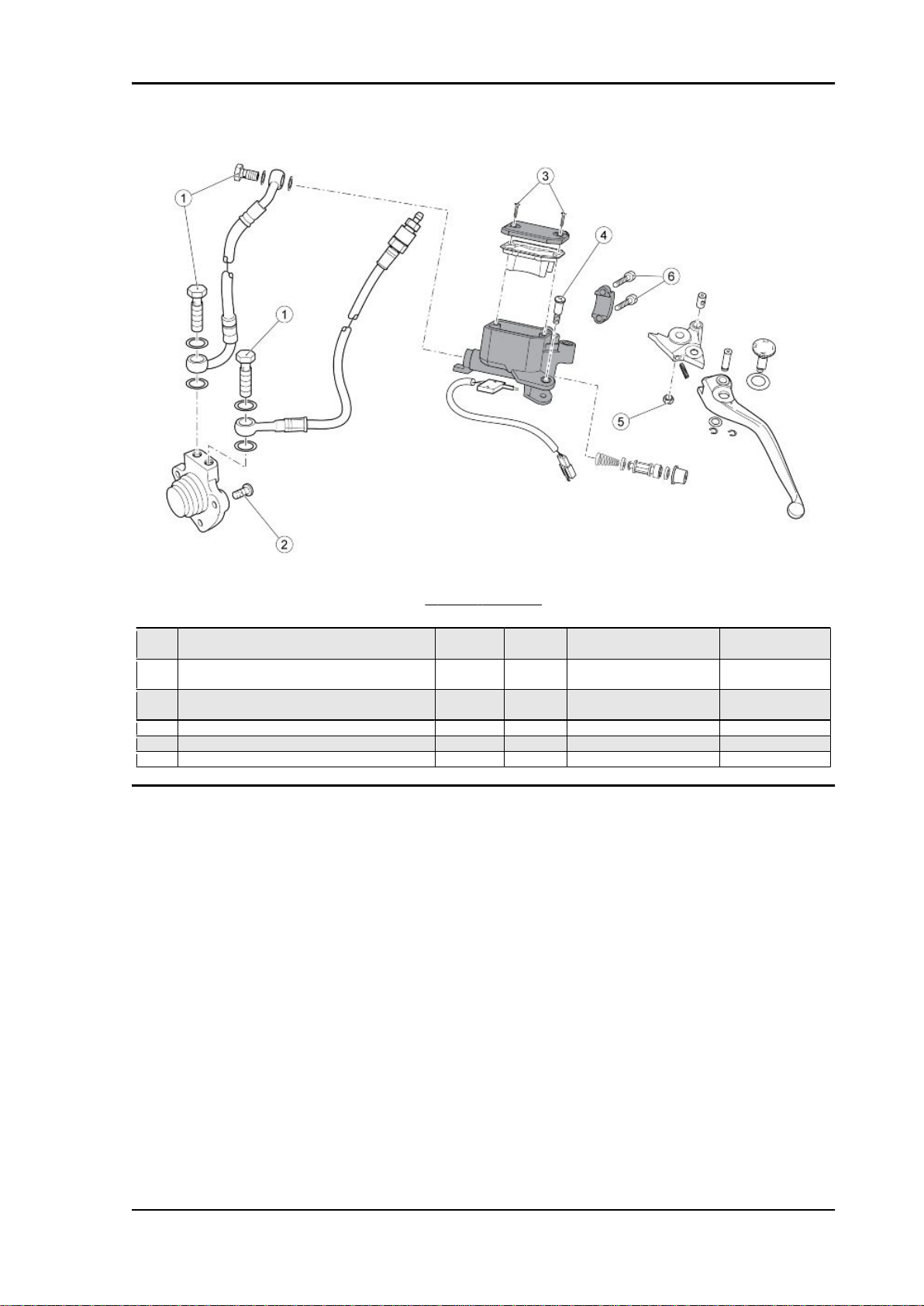
FRONT BRAKE LEVER
pos.
1 Viti TBEI fissaggio interruttore M4x12 1 3 Nm (2.21 lbf ft) 2 Lever pin M6 1 5-7 Nm (3.69-5.16 - lbf ft) 3 Viti fissaggio tappo serbatoio - 2 0.8-1.5 Nm (0.59-1.11 lbf
4 Dado perno leva M6 1 10 Nm (7.38 - lbf ft) 5 Viti fissaggio cavallotto M6 2 10 Nm (7.38 lbf ft) 6 Viti fissaggio tubo olio M10 1 23-26 Nm (16.96-19.18 lbf
Description Type Quantity Torque Notes
ft)
ft)
-
-
CHAR - 20
Stelvio 1200 NTX MY11 Characteristics
Revente Interdite - Revendita Vietata - Resaling Forbiden - Wiederverkauf Verboten
CLUTCH CONTROL
pos.
1 Viti fissaggio tubo olio M10 3 23-26 Nm (16.96-19.18 lbf
2 Viti TE Flang. fissaggio cilindro comando fri3 Viti fissaggio tappo serbatoio - 2 0.8-1.5 Nm (0.59-1.11 lbf
4 Lever pin - 1 5-7 Nm (3.69-5.16 lbf ft) -
5 Dado perno leva M6 1 10 Nm (7.38 lbf ft) 6 Viti fissaggio cavallotto - 2 10 Nm (7.38 lbf ft) -
Description Type Quantity Torque Notes
ft)
M6 3 10 Nm (7.38 lbf ft) -
zione
ft)
-
-
CHAR - 21

Characteristics Stelvio 1200 NTX MY11
Revente Interdite - Revendita Vietata - Resaling Forbiden - Wiederverkauf Verboten
FRONT MUDGUARD
pos.
1 Viti TBEI Flang. fissaggio parafango anteriore M5x12 6 6 Nm (4.42 lbf ft) -
Description Type Quantity Torque Notes
FRONT WHEEL
pos.
1 Viti TE Flang. fissaggio dischi freno M8x20 12 25 Nm (18.44 lbf ft) 2 Nut fixing wheel pin - 1 80 Nm (59.00 lbf ft) 3 Vite flang. fissaggio sensore - 1 6 Nm (4.42 lbf ft) Loct. 243
CHAR - 22
Description Type Quantity Torque Notes
Stelvio 1200 NTX MY11 Characteristics
Revente Interdite - Revendita Vietata - Resaling Forbiden - Wiederverkauf Verboten
pos. Description Type Quantity Torque Notes
4 Vite TCB fissaggio passacavo M4x6 1 3 Nm (2.21 lbf ft) -
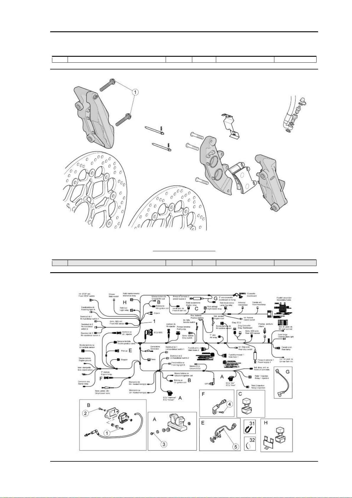
FRONT BRAKE CALLIPERS
pos.
1 Viti TE Flang. fissaggio pinze M10x55 4 50 Nm (36.88 lbf ft) -
Description Type Quantity Torque Notes
Central part
CHAR - 23

Characteristics Stelvio 1200 NTX MY11
Revente Interdite - Revendita Vietata - Resaling Forbiden - Wiederverkauf Verboten
MAIN CABLE HARNESS
pos. Description Type Quantity Torque Notes
1 Viti TE Flang. fissaggio piastre bobine M6x20 2+2 10 Nm (7.38 lbf ft) 2 Viti TCEI fissaggio bobine - 2+2 2 Nm (1.47 lbf ft) 3 Viti TCEI fissaggio centralina - 2 10 Nm (7.38 lbf ft) 4 Viti TCEI fissaggio supporto sensore temp.
olio
5 Viti TCEI fissaggio sensore di fase - 2 3 Nm (2.21 lbf ft) -
M10x20 1 11 Nm (8.11 lbf ft) Loct. 243
CAVALLETTO CENTRALE E LATERALE
pos.
1 Viti TCEI fissaggio cavalletto centrale M10x30 2 50 Nm (36.88 lbf ft) Loct. 270
2 Viti TE Flang. fissaggio piastre M8 2 25 Nm (18.44 lbf ft) 3 Screw M8x35 1 25 Nm (18.44 lbf ft) 4 Viti TBEI fissaggio piastre M12x35 4 80 Nm (59.00 lbf ft) 5 Viti TCEI fissaggio interruttore cavalletto M5 2 6 Nm (4.42 lbf ft) Loct. 243
7 Dado fissaggio cavalletto laterale M10 1 30 Nm (22.13 lbf ft) Loct. 243
Description Type Quantity Torque Notes
CHAR - 24
Stelvio 1200 NTX MY11 Characteristics
Revente Interdite - Revendita Vietata - Resaling Forbiden - Wiederverkauf Verboten
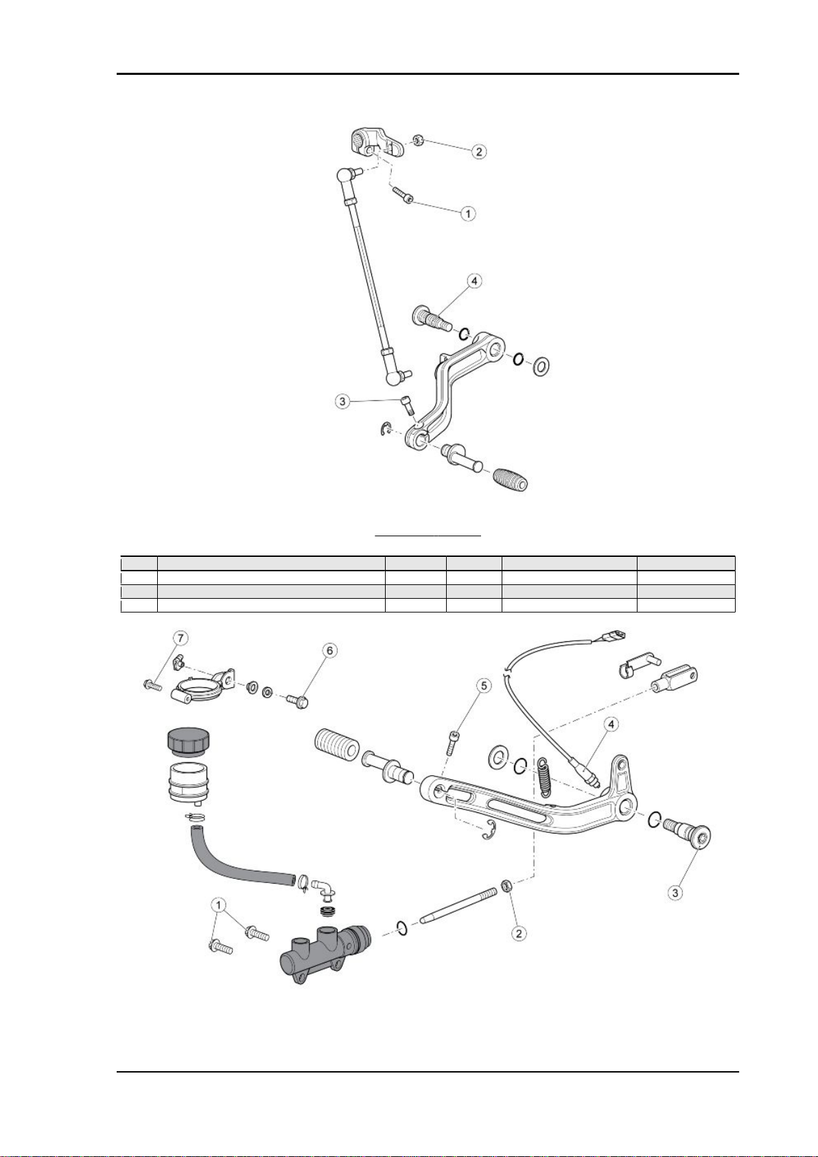
COMANDO CAMBIO
pos.
1 Viti TCEI fissaggio leva rinvio cambio M6x20 1 10 Nm (7.38 lbf ft) 2 Dadi fissaggio tirante - 2 10 Nm (7.38 lbf ft) 3 Vite TCEI fissaggio piolo leva freno M6x16 1 10 Nm (7.38 lbf ft) 4 Brake lever pin M8 1 15 Nm (11.06 lbf ft) Loct. 243
Description Type Quantity Torque Notes
CHAR - 25
Characteristics Stelvio 1200 NTX MY11
Revente Interdite - Revendita Vietata - Resaling Forbiden - Wiederverkauf Verboten
REAR BRAKE LEVER
pos. Description Type Quantity Torque Notes
1 Viti te Flang. fissaggio pompa freno M6x20 2 10 Nm (7.38 lbf ft) Loct. 243
2 Dado bloccaggio asta pompa freno - 1 10 Nm (7.38 lbf ft) 3 Brake lever pin M8 1 15 Nm (11.06 lbf ft) Loct. 243
4 Stop switch M6 1 10 Nm (7.38 lbf ft) 5 Vite TCEI fissaggio piolo leva freno - 1 10 Nm (7.38 lbf ft) 6 Vite TE Flang. fissaggio supporto serbatoio M6x16 1 10 Nm (7.38 lbf ft) 7 Vite SWP autofil. per supporto serbatoio M5x20 1 Manual -
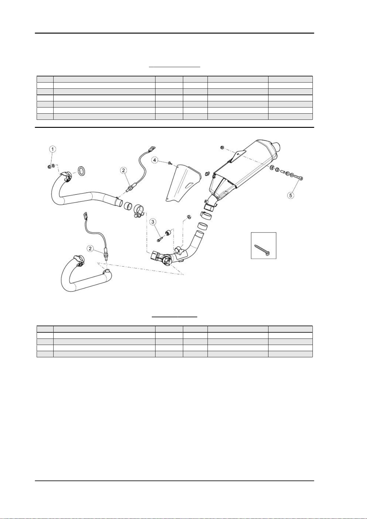
EXHAUST SYSTEM
pos.
1 Dadi Flang. fissaggio collettori M8 4 25 Nm (18.44 lbf ft) 2 Oxygen sensor fastener - 2 38 Nm (28.03 lbf ft) 3 Vite TE Flang. fissaggio parte centrale M10x55 1 25 Nm (18.44 lbf ft) 4 Viti fissaggio protezione - 2 10 Nm (7.38 lbf ft) 5 Vite TCEI fissaggio silenziatore a telaio M8x60 1 25 Nm (18.44 lbf ft) -
CHAR - 26
Description Type Quantity Torque Notes
Stelvio 1200 NTX MY11 Characteristics
Revente Interdite - Revendita Vietata - Resaling Forbiden - Wiederverkauf Verboten
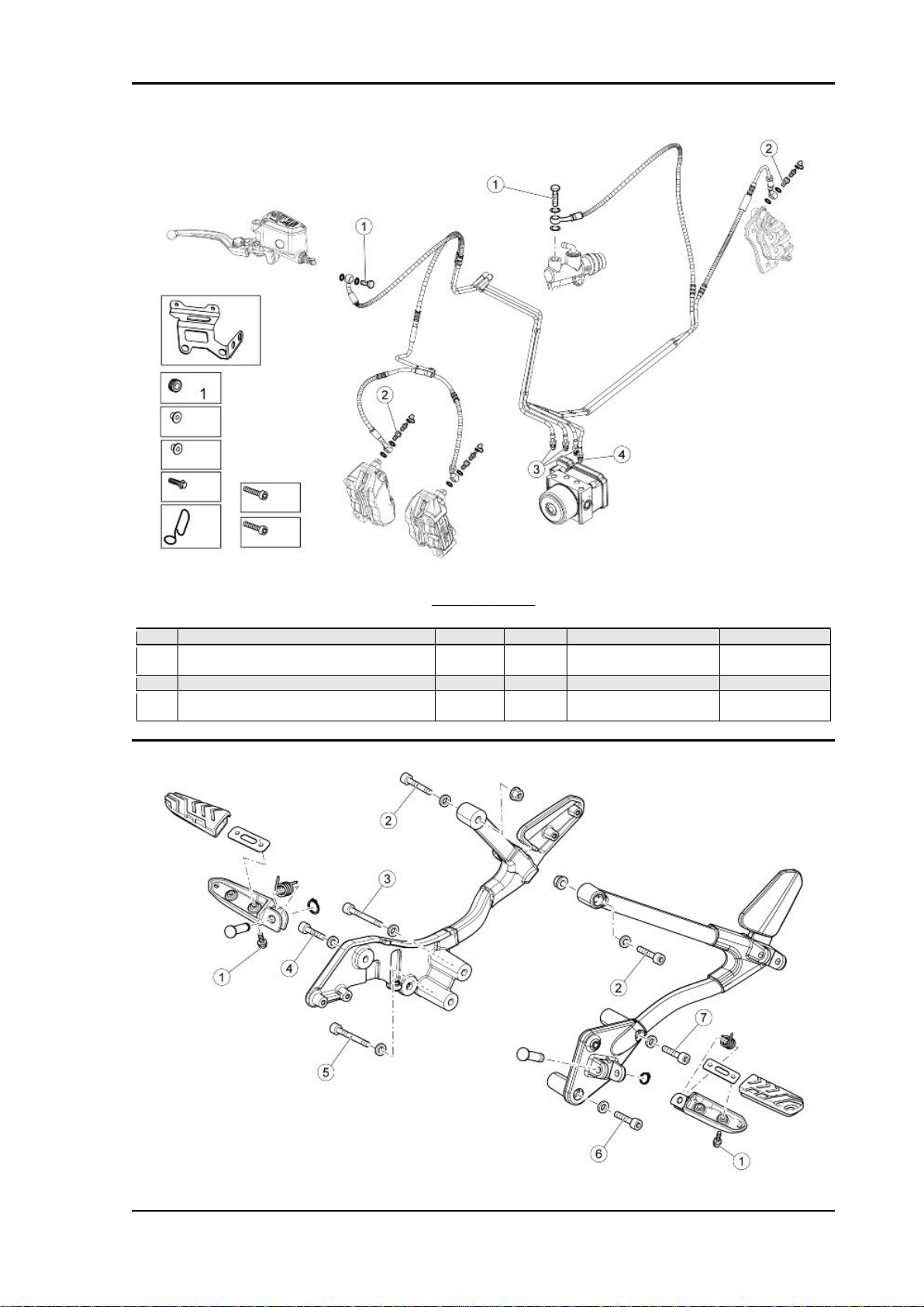
BRAKE SYSTEM
pos.
1 Brake pipe slot screw on the pump M10 2 25 Nm (18.44 lbf ft) 2 Joint with brake pipes retainer bleeding on the
3 Brake pipes joint on the ABS hydraulic unit - 3 25 Nm (18.44 lbf ft) 4 Brake pipes joint on the ABS hydraulic unit M12 1 30-34 Nm (22.13-25.08 lbf
Description Type Quantity Torque Notes
M10 3 25 Nm (18.44 lbf ft) -
calliper
ft)
-
CHAR - 27

Characteristics Stelvio 1200 NTX MY11
Revente Interdite - Revendita Vietata - Resaling Forbiden - Wiederverkauf Verboten
SUPPORTO E PEDANE PILOTA
pos. Description Type Quantity Torque Notes
1 Viti Flang. fissaggio piastrine - 4 10 Nm (7.38 lbf ft) 2 Viti TCEI fissaggio supporto pedane M8x35 2 25 Nm (18.44 lbf ft) 3 Vite fissaggio supporto pedane - 1 25 Nm (18.44 lbf ft) 4 Vite TCEI fissaggio supporto pedane M8x25 1 25 Nm (18.44 lbf ft) 5 Vite fissaggio supporto pedane - 1 25 Nm (18.44 lbf ft) 6 Vite TCEI fissaggio supporto pedane M8x60 1 25 Nm (18.44 lbf ft) 7 Vite fissaggio supporto pedane - 1 25 Nm (18.44 lbf ft) -
PASSENGER FOOTRESTS
pos.
1 Viti TE Flang. fissaggio piastrine - 4 10 Nm (7.38 lbf ft) 2 Viti TE Flang. fissaggio protezione pedana
Description Type Quantity Torque Notes
M6x12 2 10 Nm (7.38 lbf ft) -
passeggero SX
CHAR - 28
Stelvio 1200 NTX MY11 Characteristics
Revente Interdite - Revendita Vietata - Resaling Forbiden - Wiederverkauf Verboten
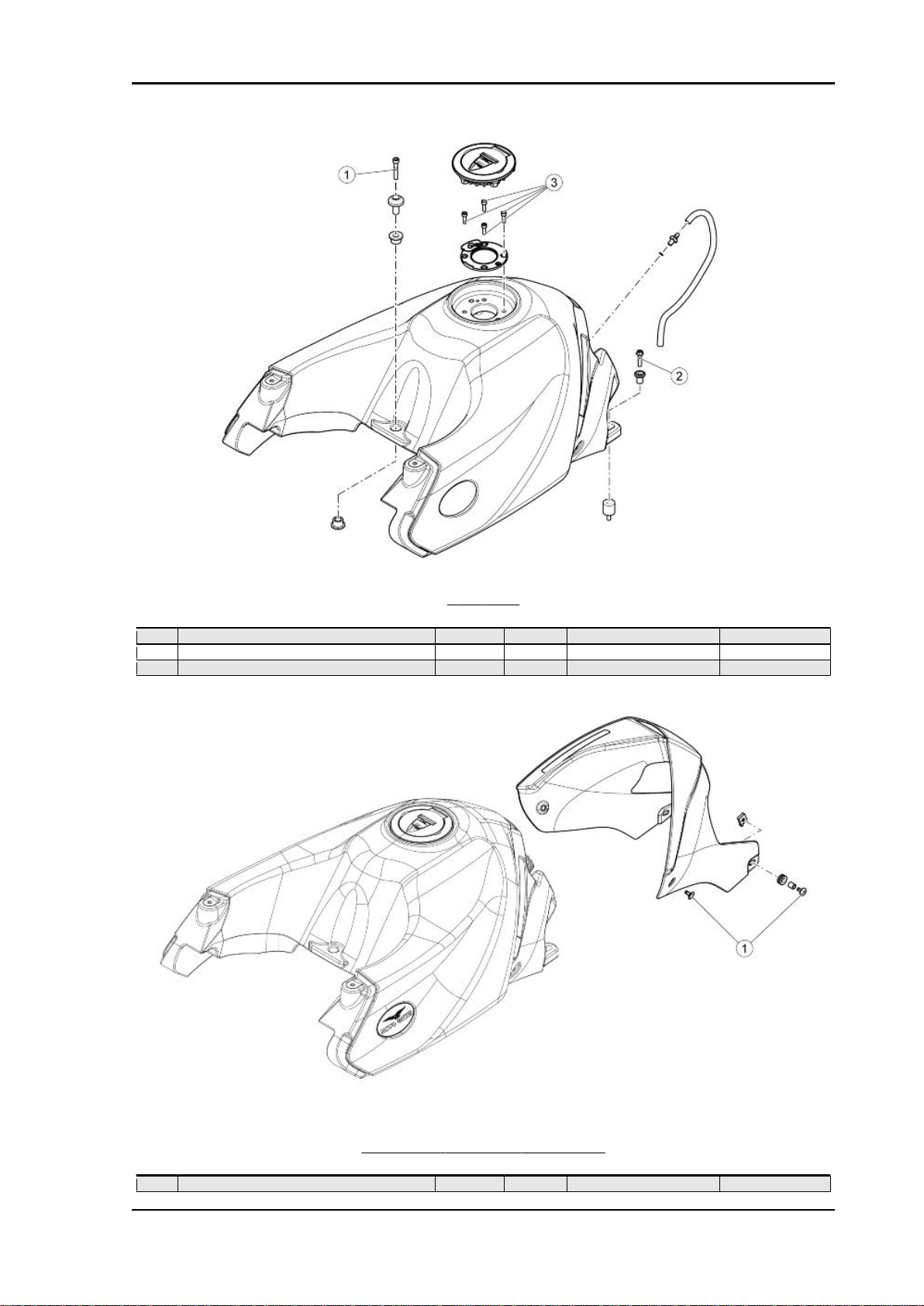
FUEL TANK
pos.
1 Vite TCEI fissaggio anteriore M6x35 1 10 Nm (7.38 lbf ft) 2 Vite TE Flang. fissaggio posteriore M6x25 2 10 Nm (7.38 lbf ft) 3 Viti TCEI fissaggio tappo benzina M5x15 4 4 Nm (2.95 lbf ft) -
Description Type Quantity Torque Notes
COPERTURA SERBATOIO CARBURANTE
pos.
1 Vite TBEI Flang. fissaggio copertura - 4 5 Nm (3.69 lbf ft) -
Description Type Quantity Torque Notes
CHAR - 29
Characteristics Stelvio 1200 NTX MY11
Revente Interdite - Revendita Vietata - Resaling Forbiden - Wiederverkauf Verboten
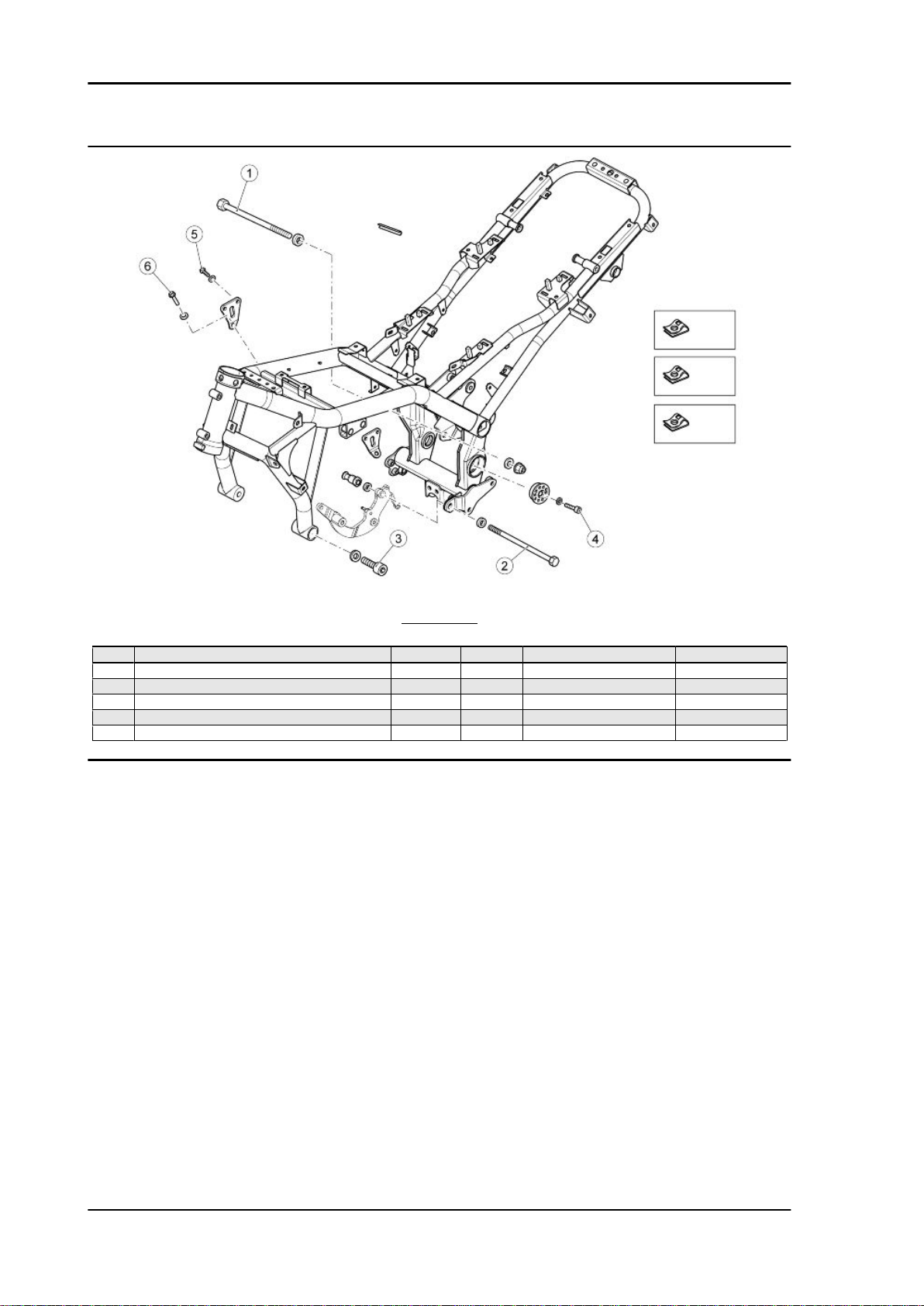
CHASSIS
pos.
1 Pin M12 1 50 Nm (36.88 lbf ft) 2 Pin M12x260 1 50 Nm (36.88 lbf ft) 3 Viti TCEI fissaggio anteriore motore a telaio M12x50 2 80 Nm (59.00 lbf ft) 4 Screws M8x14 2 25 Nm (18.44 lbf ft) 5 Viti TE Flang. M8x25 4 25 Nm (18.44 lbf ft) 6 Screws M10 2 50 Nm (36.88 lbf ft) -
Description Type Quantity Torque Notes
CHAR - 30

Stelvio 1200 NTX MY11 Characteristics
Revente Interdite - Revendita Vietata - Resaling Forbiden - Wiederverkauf Verboten
Back side
REAR BODYWORK
pos.
1 Viti SWP fissaggio piastra batteria M5x20 4 Manual 2 Viti TBEI Flang. fissaggio fianchetti e para-
3 Viti TE Flang. fissaggio supporti valigie M6 4 10 Nm (7.38 lbf ft) 4 Viti TBEI Flang. fissaggio paraspruzzi M5x12 2 6 Nm (4.43 lbf ft) -
Description Type Quantity Torque Notes
M5x9 10 6 Nm (4.42 lbf ft) -
spruzzi
CHAR - 31

Characteristics Stelvio 1200 NTX MY11
Revente Interdite - Revendita Vietata - Resaling Forbiden - Wiederverkauf Verboten
LICENSE PLATE HOLDER
pos. Description Type Quantity Torque Notes
1 Viti TBEI Flang. fissaggio portatarga M5 2 6 Nm (4.43 lbf ft) 2 Viti TBEI speciali - 2 6 Nm (4.43 lbf ft) 3 Dado autobloc. flang. fissaggio catadiottro M5 1 6 Nm (4.43 lbf ft) -
TRANSMISSION CONNECTION - ENGINE
pos.
1 Reaction rod fixing screw M10x55 2 50 Nm (36.87 lbf ft) -
Description Type Quantity Torque Notes
CHAR - 32

Stelvio 1200 NTX MY11 Characteristics
Revente Interdite - Revendita Vietata - Resaling Forbiden - Wiederverkauf Verboten
REAR SWINGARM
pos.
1 Swingarm clamp fixing screw on the bushing M6x25 2 10 Nm (7.37 lbf ft) 2 2 - Swingarm fixing screw on the transmission
3 Swingarm pin on the swingarm M12 1 60 Nm (44.25 lbf ft) 4 Preloading bushing to the swingarm pin M25 1 10 Nm (7.37 lbf ft) -
Description Type Quantity Torque Notes
M10x35 4 50 Nm (36.87 lbf ft) -
housing
CHAR - 33

Characteristics Stelvio 1200 NTX MY11
Revente Interdite - Revendita Vietata - Resaling Forbiden - Wiederverkauf Verboten
LUCI POSTERIORI
pos. Description Type Quantity Torque Notes
1 Vite TBEI Flang. fissaggio fanale - 1 6 Nm (4.43 lbf ft) 2 Vite TCEI fissaggio fanale - 2 6 Nm (4.43 lbf ft) 3 Vite TCEI fissaggio fanale targa M5x25 1 6 Nm (4.43 lbf ft) -
MANIGLIONE E PORTAPACCHI
pos.
1 Vite TCEI fissaggio maniglione passeggero M6x25 4 10 Nm (7.38 lbf ft) 2 Vite TCEI fissaggio maniglione passeggero M8 2 25 Nm (18.44 lbf ft) 3 Vite fissaggio portatarga a maniglione M5 2 6 Nm (4.42 lbf ft) 4 Vite TBEI fissaggio supporti portapacchi M8x20 2 25 Nm (18.44 lbf ft) 5 Vite TBEI fissaggio supporti portapacchi M8x30 2 25 Nm (18.44 lbf ft) 6 Vite TSPEI fissaggio coperchio portapacchi M6x35 2 10 Nm (7.38 lbf ft) 7 Vite autofil. fissaggio coperchio portapacchi 5 4 Manual -
Description Type Quantity Torque Notes
CHAR - 34

Stelvio 1200 NTX MY11 Characteristics
Revente Interdite - Revendita Vietata - Resaling Forbiden - Wiederverkauf Verboten
REAR WHEEL
pos.
1 Vite TE Flang. fissaggio ruota fonica - 6 25 Nm (18.44 lbf ft) 2 Vite TE Flang. fissaggio sensore - 1 10 Nm (7.38 lbf ft) 3 Vite TE Flang. fissaggio sensore M12x65 1 110 Nm (81.13 lbf ft) -
Description Type Quantity Torque Notes
CHAR - 35

Characteristics Stelvio 1200 NTX MY11
Revente Interdite - Revendita Vietata - Resaling Forbiden - Wiederverkauf Verboten
REAR SUSPENSION
pos. Description Type Quantity Torque Notes
1 Vite TE Flang. fissaggio superiore ammortiz-
zatore
2 Vite TCEI fissaggio biella doppia/forcellone M10x82 1 50 Nm (36.88 lbf ft) 3 Vite TE fissaggio biella doppia/ammortizza-
tore
4 Vite TE flang. fissaggio biella singola/biella
doppia
5 Vite TE flang. fissaggio biella singola al telaio M10x85 1 50 Nm (36.88 lbf ft) -
M10x80 1 50 Nm (36.88 lbf ft) -
M10x47 1 40 Nm (29.50 lbf ft) M10x95 1 50 Nm (36.88 lbf ft) -
SADDLE
pos.
1 Vite TBEI fissaggio piastra attacco sella M6 2 10 Nm (7.38 lbf ft) 2 Dado serratura - 1 Manual -
CHAR - 36
Description Type Quantity Torque Notes

Stelvio 1200 NTX MY11 Characteristics
Revente Interdite - Revendita Vietata - Resaling Forbiden - Wiederverkauf Verboten
Engine
LUBRICATION SYSTEM
pos.
1 Pump outlet oil pipe nipple M14x1.5 1 40 Nm (29.50 lbf ft) 2 Slot screw for oil pipe on the cylinder head M14x1.5 2 20 Nm (14.75 lbf ft) 3 Nipple on the radiator and the oil pipe M16x1.5 2 20 Nm (14.75 lbf ft) Apply vaseline oil
4 Oil delivery pipe to radiator slot screw M14x1.5 1 35 Nm (25.81 lbf ft) 5 Jets fixing screw - 3 Using a "T" spanner, close
6 Minimum oil pressure sensor M12 1 25 Nm (18.44 lbf ft) 7 Intake oil filter fixing screw - 2 4 Nm (2.95 lbf ft) -
Description Type Quantity Torque Notes
Loctite 243
by hand
CHAR - 37

Characteristics Stelvio 1200 NTX MY11
Revente Interdite - Revendita Vietata - Resaling Forbiden - Wiederverkauf Verboten
ALTERNATOR
pos.
1 Generator control pulley locking nut M16 1 80 Nm (59.00 lbf ft) Loctite 243
2 Generator upper fixing screw M8 1 22 Nm (16.23 lbf ft) 3 Generator lower fixing screw M10x60 1 30 Nm (22.13 lbf ft) -
Description Type Quantity Torque Notes
CHAR - 38

Stelvio 1200 NTX MY11 Characteristics
Revente Interdite - Revendita Vietata - Resaling Forbiden - Wiederverkauf Verboten
CRANKCASE AND OIL SUMP
pos. Description Type Quantity Torque Notes
1 Stud bolt M8x75 2 10 Nm (7.37 lbf ft) 2 Stud bolt M8x66 3 10 Nm (7.37 lbf ft) 3 Crankshaft rear support flange fixing screw M8x25 8 26 Nm (19.18 lbf ft) 4 Oil cap on the crankcase - 2 25 Nm (18.44 lbf ft) 5 Flange fixing screw under the crankcase M6x60 2 10 Nm (7.37 lbf ft) 6 Flange fixing screw under the crankcase - 2 10 Nm (7.37 lbf ft) 7 Oil sump fixing screw (filter contour) M6x35 4 10 Nm (7.37 lbf ft) 8 Oil sump fixing screw M6 14 10 Nm (7.37 lbf ft) 9 Cover on the flange under the crankcase - 2 20 Nm (14.75 lbf ft) 10 Magnetic oil drainage cap - 1 20 Nm (14.75 lbf ft) 11 Gear to engine fixing nut M8 5 20 Nm (14.75 lbf ft) 12 Gear to engine fixing screw - 1 20 Nm (14.75 lbf ft) Loctite 542
GEAR INTERNAL CONTROLS
pos.
1 Spring guide pin - 1 24 Nm (17.70 lbf ft) Loctite 243
Description Type Quantity Torque Notes
CHAR - 39

Characteristics Stelvio 1200 NTX MY11
Revente Interdite - Revendita Vietata - Resaling Forbiden - Wiederverkauf Verboten
OIL SUMP COMPONENTS
pos.
1 Cover on the flange under the crankcase - 1 40 Nm (29.50 lbf ft) 2 Oil filter joint - 1 10 Nm (7.37 lbf ft) Loctite 243
3 Oil sump pipe - 1 20 Nm (14.75 lbf ft) Loctite 648
4 Oil filter - 1 15 Nm (11.06 lbf ft) Engine oil
5 Rose pipe fixing screw M6 - 10 Nm (7.37 lbf ft) 6 Maximum pressure valve cover M18 1 40 Nm (29.50 lbf ft) -
Description Type Quantity Torque Notes
CHAR - 40

Stelvio 1200 NTX MY11 Characteristics
Revente Interdite - Revendita Vietata - Resaling Forbiden - Wiederverkauf Verboten
CYLINDER HEAD COVERS
pos. Description Type Quantity Torque Notes
1 Special cylinder head fixing screw - 8 8 Nm (5.90 lbf ft) Locked with cross
2 Spark plug cover fixing screw M5x10 2 8 Nm (5.90 lbf ft) -
sequence
GENERATOR COVER
pos.
1 Timing system cover cap fixing screw M6x20 2 10 Nm (7.37 lbf ft) Loctite 243
2 Timing system cover fixing screw M8x55 4 25 Nm (18.44 lbf ft) 3 Timing system cover fixing screw M6x30 9 12 Nm (8.85 lbf ft) 4 Generator cover fixing screw M6x16 5 12 Nm (8.85 lbf ft) -
Description Type Quantity Torque Notes
CHAR - 41

Characteristics Stelvio 1200 NTX MY11
Revente Interdite - Revendita Vietata - Resaling Forbiden - Wiederverkauf Verboten
AIR FILTER
pos.
1 Vite fissaggio cassa filtro aria a telaio - 2 10 Nm (7.38 lbf ft) 2 Air filter box cover fastening screw SWP 5x20 6 3 Nm (2.21 lbf ft) -
Description Type Quantity Torque Notes
THROTTLE BODY
pos.
1 Intake pipe fixing screw - 6 10 Nm (7.37 lbf ft) -
CHAR - 42
Description Type Quantity Torque Notes

Stelvio 1200 NTX MY11 Characteristics
Revente Interdite - Revendita Vietata - Resaling Forbiden - Wiederverkauf Verboten
pos. Description Type Quantity Torque Notes
2 Flange fixing screw on the throttle body M5x12 2 6 Nm (4.42 lbf ft) -
CLUTCH
pos.
1 Clutch to crankshaft fixing screw - 6 42 Nm (30.98 lbf ft) Tighten with cross
2 Clutch external flange fixing screw on flywheel M7x16 6 20 Nm (14.75 lbf ft) Loctite 243
3 Start-up crown fixing screw on flywheel - 6 10 Nm (7.37 lbf ft) Loctite 243
4 Clutch control cylinder fixing screw - 3 10 Nm (7.37 lbf ft) Loctite 243
Description Type Quantity Torque Notes
sequence
CHAR - 43

Characteristics Stelvio 1200 NTX MY11
Revente Interdite - Revendita Vietata - Resaling Forbiden - Wiederverkauf Verboten
CONNECTING ROD ASSEMBLY - CYLINDERS
pos. Description Type Quantity Torque Notes
1 Thermal group fixing stud bolt M10x1.25 8 5 Nm (3.69 lbf ft) Loctite 243
2 Connecting rod screws - 4 40 Nm (29.50 lbf ft) Pre-tightening
2 Connecting rod screws - 4 80 Nm (59.00 lbf ft) Final tightening
3 Right hydraulic tensioner cover - 1 42 Nm (30.98 lbf ft) 4 Left hydraulic tensioner cover - 1 30 Nm (22.13 lbf ft) -
FUEL SUPPLY SYSTEM
pos.
1 Vite fissaggio protezioni corpo farfallato M6 2 10 Nm (7.38 lbf ft) -
Description Type Quantity Torque Notes
CHAR - 44

Stelvio 1200 NTX MY11 Characteristics
Revente Interdite - Revendita Vietata - Resaling Forbiden - Wiederverkauf Verboten
BLOW-BY SYSTEM
pos.
1 Vite fissaggio distanziale vaso espansione
2 Reduction joint for oil return pipe - 1 20 Nm (14.75 lbf ft) -
3 Oil return pipe (on sump) - 1 20 Nm (14.75 lbf ft) Vaseline oil
Description Type Quantity Torque Notes
Blow - By a motore
SWP
M5x14
1 10 Nm (7.38 lbf ft) -
CHAR - 45

Characteristics Stelvio 1200 NTX MY11
Revente Interdite - Revendita Vietata - Resaling Forbiden - Wiederverkauf Verboten
STARTER MOTOR
pos. Description Type Quantity Torque Notes
1 Starter motor fixing screw - 2 25 Nm (18.44 lbf ft) 2 Stud bolt - 1 10 Nm (7.37 lbf ft) 3 Starter motor cover fixing screw M6x10 2 8 Nm (5.90 lbf ft) -
OIL PUMP
pos.
1 Oil pump fixing screw M6x45 3 10 Nm (7.37 lbf ft) Loctite 243
2 Oil pump driven gear locking nut M6 1 8 Nm (5.90 lbf ft) Loctite 243
3 Oil pressure valve cap - 1 40 Nm (29.50 lbf ft) -
Description Type Quantity Torque Notes
CHAR - 46

Stelvio 1200 NTX MY11 Characteristics
Revente Interdite - Revendita Vietata - Resaling Forbiden - Wiederverkauf Verboten
OIL RADIATOR
pos.
1 Viti fissaggio radiatore a telaio M6x30 3 10 Nm (7.38 lbf ft) -
Description Type Quantity Torque Notes
TESTA DESTRA
Pos.
1 Movable chain tensioner pad fixing screw - 1 20 Nm (14.75 lbf ft) Loctite 243
Descrizione Tipo Quantità Coppia Note
CHAR - 47

Characteristics Stelvio 1200 NTX MY11
Revente Interdite - Revendita Vietata - Resaling Forbiden - Wiederverkauf Verboten
Pos. Descrizione Tipo Quantità Coppia Note
2 Head tightening nut M10x1.25 4 15 Nm (11.06 lbf ft) Engine Oil Pre2 Head tightening nut M10x1.25 4 42 Nm (30.98 lbf ft) Final tightening
3 Head tightening screws (chain compartment) M6x120 2 10 Nm (7.37 lbf ft) 4 Plate locking screw and timing gear - 1 30 Nm (22.13 lbf ft) Loctite 243
5 Timing cover fixing screw on the cylinder head M5x10 2 8 Nm (5.90 lbf ft) 6 Camshaft support fixing screw - 6 18 Nm (13.28 lbf ft) 7 Vite fissaggio molla a tazza - 1 18 Nm (13.28 lbf ft) -
tightening
TESTA SINISTRA
Pos.
1 Movable chain tensioner pad fixing screw - 1 20 Nm (14.75 lbf ft) Loctite 243
2 Head tightening nut M10x1.25 4 15 Nm (11.06 lbf ft) Engine Oil Pre-
2 Head tightening nut M10x1.25 4 42 Nm (30.98 lbf ft) Final tightening
3 Head tightening screws (chain compartment) M6x120 2 10 Nm (7.37 lbf ft) 4 Plate locking screw and timing gear - 1 30 Nm (22.13 lbf ft) Loctite 243
5 Timing cover fixing screw on the cylinder head M5x10 2 8 Nm (5.90 lbf ft) 6 Camshaft support fixing screw - 6 18 Nm (13.28 lbf ft) 7 Vite fissaggio molla a tazza - 1 18 Nm (13.28 lbf ft) -
Descrizione Tipo Quantità Coppia Note
tightening
CHAR - 48

Stelvio 1200 NTX MY11 Characteristics
Revente Interdite - Revendita Vietata - Resaling Forbiden - Wiederverkauf Verboten
TIMING SYSTEM CONTROL
pos.
1 Control, timing system, shaft support flange
2 Bearing fixing screw M6x16 1 10 Nm (7.37 lbf ft) Loctite 243
3 Driving gears locking nut on the crankshaft M25 1 200 Nm (147.51 lbf ft) Loctite 601
4 Timing system driven gear locking nut M18 1 25 Nm (18.44 lbf ft) Pre-tightening
4 Timing system driven gear locking nut M18 1 150 Nm (110.63 lbf ft) Final tightening
Description Type Quantity Torque Notes
M6x14 2 8 Nm (5.90 lbf ft) -
fixing screw
CHAR - 49

Characteristics Stelvio 1200 NTX MY11
Revente Interdite - Revendita Vietata - Resaling Forbiden - Wiederverkauf Verboten
GEARBOX
pos. Description Type Quantity Torque Notes
1 Clutch housing to gearbox fixing screw M6x55 14 13 Nm (9.59 lbf ft) 2 Neutral sensor - 1 10 Nm (7.37 lbf ft) 3 Breather stud bolt - 1 8 Nm (5.90 lbf ft) Loctite 243
4 Gear oil magnetic drainage cap - 1 24 Nm (17.70 lbf ft) 5 Oil filler cap M18x1.5 1 28 Nm (20.65 lbf ft) -
Overhaul data
Assembly clearances
Cylinder - piston assy.
Measurement of the cylinder diameter must be done at three heights, turning the dial gauge 90°.
Check that cylinders and pistons are of the same selection types (D, E, F).
Check clearance between cylinders and pistons on the selected diameter; if it exceeds the value specified, it is necessary to replace cylinders and pistons.
The pistons of an engine must be balanced; a weight difference of up to 1.5 g (0.0033 lb) is allowed.
PISTON - CYLINDER SELECTION TYPES
Specification
Piston diameter - selection D 94.935 - 94.945 mm (3.73759 - 3.73798 in)
Cylinder diameter - selection D 95.000 - 95.010 mm (3.74015 - 3.74054 in)
Piston diameter - selection E 94.945 - 94.955 mm (3.73798 - 3.73837 in)
Cylinder diameter - selection E 95.010 - 95.020 mm (3.74054 - 3.74093 in)
Piston diameter - selection F 94.955 - 94.965 mm (3.73837 - 3.73877 in)
Cylinder diameter - selection F 95.020 - 95.030 mm (3.74093 - 3.74133 in)
Desc./Quantity
CHAR - 50

Stelvio 1200 NTX MY11 Characteristics
Revente Interdite - Revendita Vietata - Resaling Forbiden - Wiederverkauf Verboten
PIN - PISTON COUPLING
Specification Desc./Quantity
Pin diameter 21.998 - 21.994 mm (0.86606 - 0.86590 in)
Pin hole diameter on piston 22.016 - 22.011 mm (0.86677 - 0.86657 in)
Clearance between pin and holes on piston 0.013 - 0.022 mm (0.00051 - 0.00087 in)
Piston rings
On each piston there are:
•
1 top piston ring;
•
1 middle piston ring;
•
1 oil scraper piston ring.
Turn the rings so that the coupling ends are 120 degrees from each other.
CLEARANCE BETWEEN PISTON RINGS AND SEATS ON PISTON
Specification Desc./Quantity
Top ring 0.030 - 0.065 mm (0.00118 - 0.00256 in)
Middle ring 0.020 - 0.055 mm (0.00079 - 0.00216 in)
Oil scraper ring 0.010 - 0.045 mm (0.00039 - 0.00177 in)
Gap between the end of the piston rings inserted in the cylinder:
•
Top and middle piston ring: 0.40 - 0.65 mm (0.00158 - 0.00255 in)
•
Oil scraper piston ring: 0.30 - 0.60 mm (0.00118 - 0.00236 in).
Crankcase - crankshaft - connecting rod
CRANKSHAFT SEAT (TIMING SYSTEM SIDE)
Specification
Diameter of crankshaft main journal, timing system side 37.975 - 37.959 mm (1.49507 - 1.49444 in)
Inside diameter of crankshaft bushing, timing system side 38.016 - 38.0 mm (1.49669 - 1.49606 in)
Clearance between bushing and main journal (timing system
side)
0.025 - 0.057 mm (0.00098 - 0.00224 in)
CRANKSHAFT SEAT ( CLUTCH SIDE)
Specification
Diameter of crankshaft main journal, clutch side 53.97 - 53.961 mm (2.12480 - 2.12444 in)
Inside diameter of crankshaft bushing on clutch-side flange 54.019 - 54.0 mm (2.12673 - 2.12598 in)
Clearance between bushing and main journal (clutch side) 0.030 - 0.058 mm (0.00118 - 0.00228 in)
Desc./Quantity
Desc./Quantity
CHAR - 51

Characteristics Stelvio 1200 NTX MY11
Revente Interdite - Revendita Vietata - Resaling Forbiden - Wiederverkauf Verboten
Slot packing system
•
Fit both pistons on the connecting rods.
•
Working from both sides, fit the gasket
between the crankcase and the cylinder on the crankcase.
•
Fit both cylinders.
•
Take the left cylinder piston to TDC and
lock crankshaft rotation.
Specific tooling
020675Y Service shaft gear lock
•
Thoroughly clean the upper surface of
both cylinders.
•
Place the tool on the left cylinder to determine the "squish" (X).
•
Fasten the tool with the nuts of the stud
bolts.
Specific tooling
020676Y Comparator support for piston position checking
•
Reset the micrometer on the cylinder rim.
•
Move the tool so that the micrometer feeler reaches the top point of the piston crown.
•
Take note of the measurement and, according to the values found, consult the chart at the
bottom of the page to decide the thickness of the gasket to be fitted between cylinder and
head.
•
Unlock crankshaft rotation.
•
Rotate the crankshaft by 90°until the right cylinder piston reaches the TDC.
•
Lock crankshaft rotation.
•
Place the tool on the right cylinder stud bolts to determine the "squish" (X).
Specific tooling
020676Y Comparator support for piston position checking
CHAR - 52

Stelvio 1200 NTX MY11 Characteristics
Revente Interdite - Revendita Vietata - Resaling Forbiden - Wiederverkauf Verboten
•
Repeat the same operations to determine the thickness of the left cylinder gasket between
cylinder and head also for the right cylinder.
CYLINDER GASKET THICKNESS - HEAD
Specification Desc./Quantity
Value (X) -0.56 / -0.37 mm (-0.022 / -0.0146 in) gasket thickness: 0.65 mm (0.0256 in)
Value (X) -0.37 / -0.19 mm (-0.0146 / -0.0075 in) gasket thickness: 0.85 mm (0.0335 in)
Value (X) -0.19 / 0 mm (-0.0075 / 0 in) gasket thickness: 1.05 mm (0.0413 in)
Recommended products chart
RECOMMENDED PRODUCTS
Product Description Specifications
ENI i-RIDE PG RACING 10W-60 Engine oil SAE 10W - 60. As an alternative to rec-
AGIP GEAR SAE 80 W 90 Transmission oil -
AGIP GEAR MG/S SAE 85 W 90 Gearbox oil -
AGIP ARNICA SA 32 Fork oil SAE 0W - ISO VG 32
AGIP GREASE SM2 Lithium grease with molybdenum for
bearings and other points needing lubri-
cation
Neutral grease or petroleum jelly. BATTERY POLES
AGIP BRAKE 4 / BRAKE 5.1 Brake fluid As an alternative for recommended flu-
AGIP BRAKE 4 / BRAKE 5.1 Clutch fluid As an alternative for recommended flu-
ommended fluids, use top branded oils
with performances that meet or exceed
the requirements of CCMC G-4 API. SG
specifications.
NLGI 2
ids, use top branded fluids that meet or
exceed the requirements of SAE J1703,
NHTSA 116 DOT 4, ISO 4925 synthetic
fluid specifications.
ids, use top branded fluids that meet or
exceed the requirements of SAE J1703,
NHTSA 116 DOT 4, ISO 4925 synthetic
fluid specifications.
CHAR - 53

INDEX OF TOPICS
Revente Interdite - Revendita Vietata - Resaling Forbiden - Wiederverkauf Verboten
SPECIAL TOOLS S-TOOLS

Stelvio 1200 NTX MY11 Special tools
Revente Interdite - Revendita Vietata - Resaling Forbiden - Wiederverkauf Verboten
MOTORE
Stores code Description
020677Y Generator belt tensioner, lever for belt
05.91.17.30 Front cover insertion cone
020716Y Connecting rod locking
tensioning
020470Y Pin snap ring fitting tool
05.92.72.30 Timing system cover sealing ring punch
01.92.91.00 Wrench for removing the cover on sump
and filter
S-TOOLS - 55

Special tools Stelvio 1200 NTX MY11
Revente Interdite - Revendita Vietata - Resaling Forbiden - Wiederverkauf Verboten
Stores code Description
05.90.25.30 Gearbox support
19.92.96.00 Graduated dial to control ignition timing
12.91.18.01 Tool to lock the flywheel and the starting
12.91.36.00 Tool to remove the flywheel-side flange
AP8140179 Support for valve fitting/removal
AP9100838 Tool for valve pressure plate
ring gear
14.92.71.00 Tool to fit the sealing ring on the flywheelside flange
S-TOOLS - 56

Stelvio 1200 NTX MY11 Special tools
Revente Interdite - Revendita Vietata - Resaling Forbiden - Wiederverkauf Verboten
Stores code Description
12.91.20.00 Tool to fit the flywheel-side flange together with sealing ring on the crankshaft
19.92.71.00 Tool to fit the seal ring on the flywheel-
020673Y Graduated dial hub
020672Y Clutch spring centre and pusher
020674Y Piston ring clamp
side flange
020675Y Service shaft gear lock
020676Y Comparator support for piston position
checking
S-TOOLS - 57

Special tools Stelvio 1200 NTX MY11
Revente Interdite - Revendita Vietata - Resaling Forbiden - Wiederverkauf Verboten
Stores code Description
020678Y Tool for clutch rod checking
05.91.25.30 Gearbox opening
CHASSIS
Stores code Description
14.91.26.03 Hook spanner for fixing ring nut of the
clutch shaft internal body
AP8140190 Tool for steering tightening
BEVEL GEAR SET
Stores code
05.90.27.30 Gearbox support
Description
S-TOOLS - 58

Stelvio 1200 NTX MY11 Special tools
Revente Interdite - Revendita Vietata - Resaling Forbiden - Wiederverkauf Verboten
Stores code Description
05.90.27.31 Gearbox oil seal buffer
05.90.27.32 Buffer handgrip
05.90.27.33 Ball joint sealing buffer
05.90.27.34 Wrench for pinion ring nut
05.90.27.35 Pinion oil seal buffer
FRONT FORK
Stores code
AP8140146 Weight
Description
S-TOOLS - 59

Special tools Stelvio 1200 NTX MY11
Revente Interdite - Revendita Vietata - Resaling Forbiden - Wiederverkauf Verboten
Stores code Description
AP8140149 Protection for fitting operations
9100903 Marzocchi fork oil seal; ø 45 mm (1.77 in)
S-TOOLS - 60

INDEX OF TOPICS
Revente Interdite - Revendita Vietata - Resaling Forbiden - Wiederverkauf Verboten
MAINTENANCE MAIN

Maintenance Stelvio 1200 NTX MY11
Revente Interdite - Revendita Vietata - Resaling Forbiden - Wiederverkauf Verboten
Maintenance chart
NOTE
CARRY OUT MAINTENANCE OPERATIONS AT HALF THE INTERVALS SPECIFIED IF THE VEHICLE IS USED IN PARTICULAR RAINY OR DUSTY CONDITIONS, OFF ROAD OR FOR TRACK
USE.
Routine maintenance table
I: INSPECT AND CLEAN, ADJUST, LUBRICATE OR REPLACE IF NECESSARY
C: CLEAN, R: REPLACE, A: ADJUST, L: LUBRICATE
(1) Check and clean and adjust or replace, if necessary, before every journey.
(2) Replace every 2 years or 20000 Km (12427 mi).
(3) Replace every 4 years.
(4) Check at each engine start.
(5) It is recommended to lubricate stands and footrests periodically with spray grease after use in particularly hard conditions (dirty with salts, dust, etc.) or after long inactivity periods.
(6) Lubricate if you are riding in the rain, on wet roads or after the vehicle has been washed.
ROUTINE MAINTENANCE TABLE
km x 1,000
Exhaust pipe flange bolts I I I I I
Spark plugs R R R R R R R R
Carburetion at idle (CO) I I I I I I I I
Throttle body C C C C
Stands (5) I I I I I I I I
Transmission cables and controls I I I I I I I I I
Alternator belt A A R A A
Steering bearings and steering clearance I I I I I I I I I
Wheel bearings I I I I I I I I
Brake discs I I I I I I I I I
Air filter I R I R I R I R
Engine oil filter R R R R R R R R R
Fork I I I I I
Vehicle general operation I I I I I I I I I
Braking systems I I I I I I I I I
Light circuit I I I I I I I I I
Safety switches I I I I I
Brake fluid (2) I I R I R I R I R
Clutch fluid (2) I I I I I I I I I
Gearbox oil R R R R R R R R R
Engine oil R R R R R R R R R
Fork oil / oil seals R R R R
Final drive oil R R R R R R R R R
Clutch lever pin (6) L L L L L L L L L
Tyres - pressure / wear (1) I I I I I I I I I
Engine idle speed A A A A A A A A A
Valve clearance adjustment A A A A A A A A A
Wheels I I I I I I I I I
Bolts and nuts tightening I I I I I I I I I
Battery terminals tightening I I I I I
Wheel nipple tightening (1) I I I I I I I I I
Cylinder synchronisation I I I I I I I I I
Footrests joint (5) I I I I I I I I
Suspension and setting I I I I I
Engine oil pressure warning light (4)
Empty oil drain pipe from the filter housing C C C C C C C C
Fuel lines (3) I I I I I I I I
1.5 10 20 30 40 50 60 70 80
MAIN - 62

Stelvio 1200 NTX MY11 Maintenance
Revente Interdite - Revendita Vietata - Resaling Forbiden - Wiederverkauf Verboten
km x 1,000 1.5 10 20 30 40 50 60 70 80
Brake lines (3) I I I I I I I I
Clutch wear I I I I I I I I
Brake pad wear (1) I I I I I I I I I
Transmission fluid
Check
• Keep the vehicle upright with both wheels on the
ground.
• Unscrew and remove the cap/dipstick (1).
• The level is correct if the oil is close to the hole
of the cap/dipstick (1).
• If the oil is lower than specified, top-up until it
reaches the cap/dipstick hole (1).
CAUTION
DO NOT ADD ADDITIVES OR ANY OTHER SUBSTANCE TO
THE FLUID. WHEN USING A FUNNEL OR ANY OTHER ELEMENT, MAKE SURE IT IS PERFECTLY CLEAN.
Replacement
CAUTION
THE UNIT MUST BE HOT WHEN THE OIL IS CHANGED AS UNDER SUCH CONDITIONS OIL IS
FLUID AND THEREFORE EASY TO DRAIN.
NOTE
RIDE SOME km (miles) TO WARM UP ENGINE OIL
•
Place a container with + 400 cm³ (25 cu in) capacity under the drainage plug (3).
•
Unscrew and remove the drainage plug (3).
•
Unscrew and remove the breather cap (2).
•
Drain the oil into the container; allow several minutes for oil to drain out completely.
•
Check and if necessary, replace the sealing washer of drainage plug (3).
•
Remove any metal scrap attached to the drainage plug (3) magnet.
•
Screw and tighten the drainage plug (3).
•
Pour new oil through the fill opening (1) until it reaches the cap/dipstick hole (1).
CAUTION
DO NOT ADD ADDITIVES OR ANY OTHER SUBSTANCE TO THE FLUID. WHEN USING A FUNNEL
OR ANY OTHER ELEMENT, MAKE SURE IT IS PERFECTLY CLEAN.
MAIN - 63

Maintenance Stelvio 1200 NTX MY11
Revente Interdite - Revendita Vietata - Resaling Forbiden - Wiederverkauf Verboten
•
Screw and tighten the caps (1 - 2).
Engine oil
Check
CAUTION
ENGINE MUST BE WARM TO CHECK ENGINE OIL LEVEL
NOTE
DO NOT LET THE ENGINE IDLE WITH THE VEHICLE AT STANDSTILL TO WARM UP THE ENGINE
AND REACH THE OPERATING TEMPERATURE OF ENGINE OIL. OIL IS BEST CHECKED AFTER
RUNNING FOR ABOUT 15 KM (10 miles).
•
Shut off the engine.
•
Keep the vehicle upright with both wheels on the ground.
•
Pull the filler plug / oil level dipstick (1)
straight out.
•
Wipe the oil level dipstick (1) clean and
reinsert it.
•
Pull it out again and check the oil level.
•
The oil level is correct when it is close
to the "MAX" mark. Otherwise, top-up
with engine oil.
CAUTION
DO NOT ADD ADDITIVES OR ANY OTHER SUBSTANCE TO THE OIL. WHEN USING A FUNNEL
OR ANY OTHER ELEMENT, MAKE SURE IT IS PERFECTLY CLEAN.
Replacement
NOTE
HOT OIL IS LESS VISCOUS AND WILL DRAIN OUT MORE EASILY AND COMPLETELY.
It is necessary to remove the metal oil sump guard in order to change the engine oil and replace the oil
filter:
•
Operating from both sides, unscrew and remove both screws (1).
•
Remove the oil sump guard.
MAIN - 64

Stelvio 1200 NTX MY11 Maintenance
Revente Interdite - Revendita Vietata - Resaling Forbiden - Wiederverkauf Verboten
•
Place a container with +4,000 cm³ (244
cu in) capacity under the drainage plug
(3).
•
Unscrew and remove the drainage
plug (3).
•
Pull out the oil filler plug / engine oil
level dipstick (4).
•
Drain the oil into the container; allow
several minutes for oil to drain out completely.
•
Insert the oil filler plug / engine oil level
dipstick (4).
•
Check and if necessary, replace the
drainage plug (3) sealing washers.
•
Remove any metal deposits attached
to the drainage plug (3) magnet.
•
Screw and tighten the drainage plug
(3).
DO NOT DISPOSE OF OIL INTO THE ENVIRONMENT.
DISPOSE OF ENGINE OIL IN A SEALED CONTAINER AND
TAKE IT TO YOUR SUPPLIER OR TO THE NEAREST USED
OIL COLLECTION CENTRE.
MAIN - 65

Maintenance Stelvio 1200 NTX MY11
Revente Interdite - Revendita Vietata - Resaling Forbiden - Wiederverkauf Verboten
Engine oil filter
Replace the engine oil filter each time you
change the engine oil.
•
Drain the engine oil completely.
•
Unscrew and remove the engine oil filter from its seat.
NOTE
NEVER REUSE AN OLD FILTER.
•
Spread a thin layer of oil on the sealing ring of the new engine oil filter.
•
Fit and screw the new oil filter in its seat.
Gearbox Oil
Inspection
CHECKING AND TOPPING UP
CAUTION
ENGINE MUST BE WARM TO CHECK GEARBOX OIL LEVEL.
NOTE
DO NOT LET THE ENGINE IDLE WITH THE VEHICLE AT STANDSTILL TO WARM UP THE ENGINE
AND REACH THE OPERATING TEMPERATURE OF ENGINE OIL. OIL IS BEST CHECKED AFTER
RUNNING FOR ABOUT 15 KM (10 miles).
•
Shut off the engine.
•
Keep the vehicle upright with both
wheels on the ground.
•
Unscrew and remove the cap/dipstick
(1) placed on the gearbox right side.
•
• The level is correct if the oil is on the
rim of the hole of the cap/dipstick (1).
If necessary:
•
Top-up with oil until it reaches the dipstick opening (1).
CAUTION
DO NOT ADD ADDITIVES OR ANY OTHER SUBSTANCE TO
THE FLUID. WHEN USING A FUNNEL OR ANY OTHER ELEMENT, MAKE SURE IT IS PERFECTLY CLEAN.
Replacement
NOTE
HOT OIL IS MORE FLUID AND WILL DRAIN OUT MORE EASILY AND COMPLETELY.
MAIN - 66

Stelvio 1200 NTX MY11 Maintenance
Revente Interdite - Revendita Vietata - Resaling Forbiden - Wiederverkauf Verboten
• Place a container with suitable capacity under the
drainage plug (2).
• Unscrew and remove the drainage plug (2).
• Unscrew and remove the filler cap (1).
• Drain the oil into the container; allow several minutes for oil to drain out completely.
• Check and replace, if necessary, the sealing
washers of drainage plug (2).
• Remove any metal scrap attached to the drainage plug (2) magnet.
• Screw and tighten the drainage plug (2).
• Pour in new oil until it reaches the dipstick opening (1).
• Tighten the filler cap (1).
CAUTION
DO NOT ADD ADDITIVES OR ANY OTHER SUBSTANCE TO
THE FLUID. WHEN USING A FUNNEL OR ANY OTHER ELEMENT, MAKE SURE IT IS PERFECTLY CLEAN.
Air filter
AIR FILTER
pos.
1 Vite fissaggio cassa filtro aria a telaio - 2 10 Nm (7.38 lbf ft) 2 Air filter box cover fastening screw SWP 5x20 6 3 Nm (2.21 lbf ft) -
Description Type Quantity Torque Notes
MAIN - 67

Maintenance Stelvio 1200 NTX MY11
Revente Interdite - Revendita Vietata - Resaling Forbiden - Wiederverkauf Verboten
•
Undo and remove the six screws.
•
Lift the filter housing cover.
•
Remove the air filter.
•
Cover the inlet duct with a clean cloth so that no foreign bodies get into the inlet ducts.
DO NOT START THE ENGINE WITHOUT THE AIR FILTER.
TO CLEAN THE FILTERING ELEMENT, USE A PRESSURE AIR JET FROM THE INSIDE TO THE
OUTSIDE.
Checking the valve clearance
If the timing system is very noisy, check the clearance between the valves and the rocking levers.
NOTE
ADJUST WITH COLD ENGINE, WITH PISTON AT TOP DEAD CENTRE (TDC) IN COMPRESSION
STROKE (VALVES CLOSED).
•
Scollegare la pipetta candela facendo
leva mediante un cacciavite attraverso
la feritoia.
CAUTION
PRESTARE ATTENZIONE A FARE LEVA SULLA GOMMA
DELLA PIPETTA CANDELA E NON SULLA CANDELA
STESSA ONDE EVITARE DI DANNEGGIARLA
MAIN - 68

Stelvio 1200 NTX MY11 Maintenance
Revente Interdite - Revendita Vietata - Resaling Forbiden - Wiederverkauf Verboten
•
Unscrew and remove the four head
cover fixing screws and collect the
sealing O-rings.
•
Remove the head cover together with
the gasket.
•
loosen the nut (1);
•
use a screwdriver on the set screw (2)
until the following clearances are obtained:
- inlet valve: 0.10 mm (0.0039 in)
- outlet valve: 0.15 mm (0.0059 in).
•
The measurement must be done using
a thickness gauge (3).
CAUTION
IF CLEARANCE IS LARGER THAN RECOMMENDED, THE TAPPET WILL BE NOISY. OTHERWISE, THE VALVES DO NOT CLOSE CORRECTLY, WHICH CAN LEAD TO PROBLEMS SUCH
AS:
•
PRESSURE DROP;
•
ENGINE OVERHEAT;
•
VALVE BURNOUT, ETC.
Braking system
Level check
Brake fluid check
•
Rest the vehicle on its stand.
•
For the front brake, turn the handlebar fully to the right.
•
For the rear brake, keep the vehicle upright so that the fluid in the reservoir is at the same
level with the plug.
•
Make sure that the fluid level in the reservoir is above the "MIN" reference mark:
MIN = minimum level
MAX = maximum level
If the fluid does not reach at least the "MIN" reference mark:
•
Check brake pads and disc for wear.
•
If the pads and/or the disc do not need replacing, top-up the fluid.
MAIN - 69

Maintenance Stelvio 1200 NTX MY11
Revente Interdite - Revendita Vietata - Resaling Forbiden - Wiederverkauf Verboten
Top-up
Front brake:
•
Unscrew the two screws (1) of the
brake fluid reservoir (2) using a Phillips
screwdriver.
•
Lift and remove the cover (3) and
screws (1) as well.
•
Remove the gasket (4).
Rear brake:
•
Unscrew and remove the cap (5).
•
Remove the gasket (6).
•
Top-up the reservoir with brake fluid to
the correct level, which is between the
two "MIN" and "MAX" reference marks.
RISK OF BRAKE FLUID SPILLS. DO NOT OPERATE THE
BRAKE LEVER WITH BRAKE FLUID RESERVOIR CAP
LOOSENED OR REMOVED.
CAUTION
AVOID PROLONGED AIR EXPOSURE OF THE BRAKE
FLUID. BRAKE FLUID IS HYGROSCOPIC AND ABSORBS
MOISTURE WHEN IN CONTACT WITH AIR. LEAVE THE
BRAKE FLUID RESERVOIR OPEN ONLY FOR THE TIME
NEEDED TO COMPLETE THE TOPPING UP PROCEDURE.
TO AVOID SPILLING FLUID WHILE TOPPING-UP, KEEP
THE TANK PARALLEL TO THE RESERVOIR EDGE (IN
HORIZONTAL POSITION).
DO NOT ADD ADDITIVES OR OTHER SUBSTANCES TO
THE FLUID.
WHEN USING A FUNNEL OR ANY OTHER ELEMENT,
MAKE SURE IT IS PERFECTLY CLEAN.
DO NOT EXCEED THE "MAX" LEVEL MARK WHEN TOPPING UP.
TOP-UP TO "MAX" LEVEL MARK ONLY WHEN BRAKE
PADS ARE NEW. WHEN TOPPING UP DO NOT EXCEED
THE "MAX" LEVEL MARK WHEN BRAKE PADS ARE
WORN AS YOU RISK SPILLING FLUID WHEN CHANGING
THE BRAKE PADS.
CHECK BRAKING EFFICIENCY. IN CASE OF EXCESSIVE
TRAVEL OF THE BRAKE LEVER OR POOR PERFORMANCE OF THE BRAKING SYSTEM, TAKE YOUR VEHICLE
MAIN - 70

Stelvio 1200 NTX MY11 Maintenance
Revente Interdite - Revendita Vietata - Resaling Forbiden - Wiederverkauf Verboten
TO AN Official Moto Guzzi Dealer, AS IT MAY BE NECESSARY TO PURGE THE AIR IN THE SYSTEM.
MAIN - 71

INDEX OF TOPICS
Revente Interdite - Revendita Vietata - Resaling Forbiden - Wiederverkauf Verboten
ELECTRICAL SYSTEM ELE SYS

Stelvio 1200 NTX MY11 Electrical system
Revente Interdite - Revendita Vietata - Resaling Forbiden - Wiederverkauf Verboten
MAIN CABLE HARNESS
pos.
1 Viti TE Flang. fissaggio piastre bobine M6x20 2+2 10 Nm (7.38 lbf ft) 2 Viti TCEI fissaggio bobine - 2+2 2 Nm (1.47 lbf ft) 3 Viti TCEI fissaggio centralina - 2 10 Nm (7.38 lbf ft) 4 Viti TCEI fissaggio supporto sensore temp.
5 Viti TCEI fissaggio sensore di fase - 2 3 Nm (2.21 lbf ft) -
Description Type Quantity Torque Notes
M10x20 1 11 Nm (8.11 lbf ft) Loct. 243
olio
ELE SYS - 73

Electrical system Stelvio 1200 NTX MY11
Revente Interdite - Revendita Vietata - Resaling Forbiden - Wiederverkauf Verboten
Components arrangement
Key:
1 Coil
2 Instrument panel
3 Fuel pump
4 Injector
5 Throttle valve potentiometer
ELE SYS - 74

Stelvio 1200 NTX MY11 Electrical system
Revente Interdite - Revendita Vietata - Resaling Forbiden - Wiederverkauf Verboten
6 Fall sensor
7 Rear light
8 Main fuses
9 Oxygen sensor
10 Battery
11 Starter motor
12 Intake air temperature sensor
13 Engine revolution sensor
14 Head temperature sensor
15 Engine control unit
16 Instrument panel air temperature sensor
17 Front headlamp
18 Alternator
19 Oil pressure sensor
20 Speed sensor
21 Auxiliary fuses
22 Relay
23 Additional headlamps
24 ABS Control unit
25 Rear speed sensor
26 ABS Fuses
Electrical system installation
INTRODUCTION
Scope and applicability
This document aims at defining the cable harness routing in order to achieve the vehicle reliability
targets.
Materials used and corresponding quantities
The electrical system consists of the following cable harnesses and parts:
•
1 Main cable harness
•
1 Ground lead
•
1 Headlamp cable harness
•
1 Fall sensor connector
•
1 Antitheft cable harness (optional equipment)
•
8 Small clamps
•
18 Medium clamps
•
1 Big clamp
ELE SYS - 75

Electrical system Stelvio 1200 NTX MY11
Revente Interdite - Revendita Vietata - Resaling Forbiden - Wiederverkauf Verboten
•
4 Reused clamps
•
7 Cable grommets
•
5 Rubber clamps
•
7 Cable grommets
•
1 Adhesive cable grommet
•
1 Cable grommet with clip
Motorcycle division
The wiring timing is subdivided in three essential
sections, as indicated in the figure.
1. Front section
2. Central section
3. Rear part
Special checks for the correct connection and laying of cables
It is extremely important that any security-locks for the following connectors are properly connected and
correctly tightened to ensure proper engine, and therefore proper vehicle, operation.
•
Instrument panel connector
•
Pick Up connector and alternator
•
Side Stand Switch Connector
•
Coils connectors
•
Control unit connectors
•
Fuel pump connector
•
Key Connector
•
Right Light Switch Connectors
•
Left Light Switch Connectors
•
ABS connector and correct positioning of the cap
•
Front and rear speed sensor connector
•
Auxiliary Fuses (rubber housing correct positioning and closing)
•
Intake air temperature sensor
•
Fuel injector connectors
The connectors in the list are circled in the different pictures. The listed connectors are considered more critical than the others because their disconnection could cause the vehicle to
stop or malfunction. Obviously, the correct connection of the other connectors is also important
and essential for proper vehicle operation.
It is also important and essential that the instructions regarding the routing and fixing of the cable harness in the various areas are followed meticulously in order to guarantee functionality and reliability.
ELE SYS - 76

Stelvio 1200 NTX MY11 Electrical system
Revente Interdite - Revendita Vietata - Resaling Forbiden - Wiederverkauf Verboten
Front side
TABLE A
1. Front headlamp
2. Small clamps
3. Cable grommet
4. Headlamp cable harness
TABLE B
1. Rubber clamps
TABLE C
1. Front brake switch
2. Faston
•
Check the faston are connected up to
the end.
TABLE D
1. Cable grommets
2. Pipe tightening clamp
3. Front ABS sensor
ELE SYS - 77

Electrical system Stelvio 1200 NTX MY11
Revente Interdite - Revendita Vietata - Resaling Forbiden - Wiederverkauf Verboten
TABLE E
1. Main cable harness
2. Small clamp
3. Middle clamp
TABLE F
1. Middle clamp
2. Clamp already present on the cable harness
ELE SYS - 78

Stelvio 1200 NTX MY11 Electrical system
Revente Interdite - Revendita Vietata - Resaling Forbiden - Wiederverkauf Verboten
TABLE G
1. Medium clamp
TABLE H
•
No part of the cable harness must protrude to the inside of the support so as
not to obstruct the forks
TABLE I
1. Clamp that groups the cable harness of the right
light switch, the front stop switch, the front ABS
sensor and the key
TABLE L
1. Medium clamps
2. Small clamps
ELE SYS - 79

Electrical system Stelvio 1200 NTX MY11
Revente Interdite - Revendita Vietata - Resaling Forbiden - Wiederverkauf Verboten
TABLE M
•
Check correct closure of the secondary
fuses housing cover
TABLE N
1. Middle clamp
2. Ground lead oriented as in the photo
3. Small clamp
4. Cable grommet
TABLE O
1. Medium clamps
TABLE P
1. Clamp that has the cable harness of the left light
switch and the key on the metal relay
2. Clamp that has the cable harness of the left light
switch on the pipe
3. Middle clamp
ELE SYS - 80

Stelvio 1200 NTX MY11 Electrical system
Revente Interdite - Revendita Vietata - Resaling Forbiden - Wiederverkauf Verboten
TABLE Q
1. Keep the cable harness outwards according to
the relay
2. Clamp
TABLE R
1. Middle clamp
TABLE S
1. Hook the clamp on the specific hole present in
the support.
2. Middle clamp
TABLE T
1. Front plug socket
2. Plug socket connector.
3. Correct alignment
4. Medium clamp to be placed after fitting the cap
so as to avoid it can remove
ELE SYS - 81

Electrical system Stelvio 1200 NTX MY11
Revente Interdite - Revendita Vietata - Resaling Forbiden - Wiederverkauf Verboten
TABLE U
1. Instrument panel
2. Instrument panel connector correctly connected
Central part
TABLE A
1. Main cable harness
2 Motor main cable harness
3. Grey taping as reference that must remain between the two covers
TABLE B
1. Engine oil pressure sensor
2. Small clamp
TABLE C
1. Generator
2. Sensor
3. Alternator positive
ELE SYS - 82

Stelvio 1200 NTX MY11 Electrical system
Revente Interdite - Revendita Vietata - Resaling Forbiden - Wiederverkauf Verboten
TABLE D
1. Pick up cable harness
2. Medium clamp that fastens the right pick-Up cable to the chassis
TABLE E
1. Reused clamp
TABLE F
1. Cable guide
2. Plastic cable guides
TABLE G
1. Neutral switch
•
Correctly fit the hood on the gear
switch
ELE SYS - 83

Electrical system Stelvio 1200 NTX MY11
Revente Interdite - Revendita Vietata - Resaling Forbiden - Wiederverkauf Verboten
TABLE H
•
Correct laying of cables for the injectors
TABLE I
1. Left injector
2. Right injector
•
Check that the steel clip is correctly placed after the connection
TABLE L
1. Middle clamp
2. Big clamp
3. Right light switch, key and front ABS sensor connections
4. Heated hand grips connectors
5. Small clamp that blocks the heated hand grips connectors to the brake pipe.
ELE SYS - 84

Stelvio 1200 NTX MY11 Electrical system
Revente Interdite - Revendita Vietata - Resaling Forbiden - Wiederverkauf Verboten
TABLE M
1. Ground cable harness
2. Battery ground lead
3. Left lambda sensor.
4. Clamp to keep the starter motor cable harness
far from the throttle bodies control pin
TABLE N
1. Starter motor
•
Make sure that the end is oriented to
the inside to avoid touching the protection of the starter motor.
ELE SYS - 85

Electrical system Stelvio 1200 NTX MY11
Revente Interdite - Revendita Vietata - Resaling Forbiden - Wiederverkauf Verboten
TABLE O
1. Starter motor cover
2. Cable grommet
•
If the cable grommet is correctly fitted,
it will be hidden by the cover.
TABLE P
1. Oxygen sensor cable harness
2. Cable grommet
•
Hook the cable grommet with the internal cable harness of the oxygen sensor
TABLE Q
1. Fuel pump
2. Fuel pump connector
3. Small clamp
TABLE R
1. Horn
2. Horn cable harness
3. Middle clamp
TABLE S
1. ABS control unit connector
•
The initial position of the connector fastener lever must be as shown in the figure
ELE SYS - 86

Stelvio 1200 NTX MY11 Electrical system
Revente Interdite - Revendita Vietata - Resaling Forbiden - Wiederverkauf Verboten
TABLE T
•
Place the connector on the opposite
side of the control unit and lower the
driving lever until the "click" that signals
the end of the stroke is heard.
TABLE U
•
TABLE V
•
When the connector is fully inserted,
the distance between the connector
and the ABS control unit must be 7.5
mm (0.29 in)
If the initial position of the connector
and the pulling level is not as the one
in "TABLE S", the connector will not
hook correctly and the distance measured will be higher than approximately
12 mm (0.47 in). In this case, repeat the
operation as described in "TABLE T"
and "TABLE U".
It is advisable to create a jig in order to check
the correct connector insertion.
ELE SYS - 87

Electrical system Stelvio 1200 NTX MY11
Revente Interdite - Revendita Vietata - Resaling Forbiden - Wiederverkauf Verboten
Back side
TABLE
1. Main fuses
2. Filter box air temperature sensor
3. Filter box
TABLE B
1. Middle clamp
2. Main cable harness
TABLE C
1. Rear plug socket
2. Cable grommet
3. ECU diagnosis connector
TABLE D
1. Adhesive cable grommet
ELE SYS - 88

Stelvio 1200 NTX MY11 Electrical system
Revente Interdite - Revendita Vietata - Resaling Forbiden - Wiederverkauf Verboten
TABLE E
1. Plastic cable guides
TABLE F
1. Medium clamp that groups the oxygen sensor
leads, the rear stop and the rear taillight cable harness
TABLE G
1. Fall sensor connector with cover
TABLE H
1. Cable grommets
ELE SYS - 89

Electrical system Stelvio 1200 NTX MY11
Revente Interdite - Revendita Vietata - Resaling Forbiden - Wiederverkauf Verboten
TABLE I
1. Cable grommet
2. Lambda leads
TABLE L
1. Reused clamps
2. Small clamp that has the lambda and the rear
stop cable together with the pipes group
ELE SYS - 90

Stelvio 1200 NTX MY11 Electrical system
Revente Interdite - Revendita Vietata - Resaling Forbiden - Wiederverkauf Verboten
General wiring diagram
Key:
1. MULTIPLE CONNECTORS
2. CLUTCH SWITCH
3. START-UP RELAY
4. MAINTENANCE RELAY
ELE SYS - 91

Electrical system Stelvio 1200 NTX MY11
Revente Interdite - Revendita Vietata - Resaling Forbiden - Wiederverkauf Verboten
5. LIGHT LOGIC RELAY
6. FOG LAMP RELAY
7. Right light switch
8. LEFT LIGHT SWITCH
9. HORN
10.AMBIENT AIR TEMPERATURE SENSOR
11.INSTRUMENT PANEL
12.IMMOBILIZER AERIAL
13.IGNITION KEY
14.HEATED HANDGRIPS
15.GPS COUPLING
16.-
17.-
18.Rear right turn indicator
19.TAILLIGHT ASSEMBLY
20.REAR LEFT TURN INDICATOR
21.LICENSE PLATE LIGHT BULB
22.REAR STOP SWITCH
23.FRONT STOP SWITCH
24.ABS CONTROL UNIT
25.FRONT WHEEL SPEED SENSOR
26.REAR WHEEL SPEED SENSOR
27.ANTITHEFT CONTROL UNIT (OPTIONAL EQUIPMENT)
28.-
29.Secondary fuses
30.STARTER MOTOR
31.MAIN FUSES 2
32.MAIN FUSES 1
33.Battery
34.PLUG SOCKET "1"
35.GENERATOR
36.MAIN INJECTION RELAY
37.AUXILIARY INJECTION RELAY
38.OIL PRESSURE SENSOR
39.NEUTRAL SENSOR
40.OXYGEN SENSOR
41.SIDE STAND SWITCH
42.FUEL RESERVE SENSOR
ELE SYS - 92

Stelvio 1200 NTX MY11 Electrical system
Revente Interdite - Revendita Vietata - Resaling Forbiden - Wiederverkauf Verboten
43.FUEL PUMP
44.INTAKE AIR TEMPERATURE SENSOR
45.Engine temperature sensor
46.IDLE MOTOR
47.THROTTLE POSITION SENSOR
48.RIGHT CYLINDER COIL
49.LEFT CYLINDER COIL
50.RIGHT SPARK PLUG
51.LEFT SPARK PLUG
52.RIGHT CYLINDER INJECTOR
53.LEFT CYLINDER INJECTOR
54.FALL SENSOR (OPTIONAL EQUIPMENT)
55.PICK-UP
56.ECU
57.FOG LIGHTS
58.FRONT LEFT TURN INDICATOR
59.COMPLETE HEADLAMP
60.TAIL LIGHT BULB
61.HIGH - LOW BEAM BULB
62.FRONT RIGHT TURN INDICATOR
63.INSTRUMENT PANEL DIAGNOSIS
64.ECU DIAGNOSIS
65.HIGH BEAM LIGHT RELAY
66.PLUG SOCKET "2"
67.OXYGEN SENSOR RH
Cable colour:
Ar orange
Az sky blue
B blue
Bi white
G yellow
Gr grey
M brown
N black
R red
Ro pink
V green
ELE SYS - 93

Electrical system Stelvio 1200 NTX MY11
Revente Interdite - Revendita Vietata - Resaling Forbiden - Wiederverkauf Verboten
Vi purple
Checks and inspections
Dashboard
Diagnosis
Changing the CODE
If you know the code, just enter it and then a new code that will be automatically stored in the memory.
If the vehicle is new, the user code is: 00000
Resetting the CODE
This function is used to set a new code when the old one is not available; in this case, at least two of
the programmed keys have to be inserted in the ignition lock.
After the first key has been inserted, the second one is requested with the following message:
INSERT KEY II
If the second key is not inserted within 20 seconds, the operation is finished.
After recognising the second key, the new code is required with the message:
ENTER NEW CODE
Once the operation is finished, the instrument panel goes back to the SET-UP menu.
DIAGNOSIS
Access to this menu (diagnosis functions), for the technical service only, after requesting a service code.
It will read: ENTER THE SERVICE CODE This vehicle code is: 10695
The functions in this menu are:
•
Exit
•
ECU diagnosis
•
Instrument Panel Errors
•
Error Clearing
•
Reset Service
•
Update
•
Change Keys
•
km / Miles
ECU ERRORS
The instrument panel receives only the current errors from the control unit.
Description Error code
Throttle Valve Error DC V DC ECU 10
Throttle Valve Error DC Gnd ECU 11
Engine Temperature Error DC V DC ECU 14
ELE SYS - 94

Stelvio 1200 NTX MY11 Electrical system
Revente Interdite - Revendita Vietata - Resaling Forbiden - Wiederverkauf Verboten
Engine Temperature Error DC Gnd ECU 15
Air Temperature Error DC V DC ECU 16
Air Temperature Error DC Gnd ECU 17
Low Battery Error ECU 20
Lambda Probe Error ECU 21
Coil 1 Error DC V DC ECU 22
Coil 1 Error DC Gnd ECU 23
Coil 2 Error DC V DC ECU 24
Coil 2 Error DC Gnd ECU 25
Injector 1 Error DC V DC ECU 26
Injector 1 Error DC Gnd ECU 27
Injector 2 Error DC V DC ECU 30
Pump Relay Error ECU 36
Local Loopback Error ECU 37
Start-up Remote Error DC V DC ECU 44
Remote Error Start-up DC Gnd ECU 45
Canister Error DC V DC ECU 46
Canister Error DC Gnd ECU 47
Battery Error Hig ECU 50
Generic ECU Error ECU 51
Signal Panel Error ECU 54
Self-adaptability Value Error ECU 55
Vehicle Speed Error ECU 56
Stepper Error AC ECU 60
Stepper Error DC V DC ECU 61
Stepper Error DC Gnd ECU 62
Not recognised error ECU 00
INSTRUMENT PANEL ERRORS
In this mode a chart is displayed showing potential errors in the immobilizer and its sensors.
This is the error decoding chart:
Description: Immobilizer failure: Key code read but not recognised. Error code: DSB 01
Description: Immobilizer failure: Key code not read (Key not inserted or transponder broken) Error code:
DSB 02
Description: Immobilizer failure: Aerial not working (Open or short-circuited). Error code: DSB 03
Description: Immobilizer failure: Internal controller failure. Error code: DSB 04
Description: - Error code: DSB 05
Description: Air temperature sensor failure. Error code: DSB 06
Description: Oil sensor failure. Error code: DSB 07
ELE SYS - 95

Electrical system Stelvio 1200 NTX MY11
Revente Interdite - Revendita Vietata - Resaling Forbiden - Wiederverkauf Verboten
Description: Oil pressure failure. Error code: DSB 08
The instrument panel keeps all previous errors stored in its memory.
DELETE ERRORS
This option deletes instrument panel errors only, a further confirmation is requested.
INSTRUMENT PANEL SOFTWARE UPGRADE
This function is used to program the instrument
panel again with a new software through Navigator.
The Display reads: "Instrument panel disconnected. Now connect the diagnosis instrument"; the
instrument panel will connect normally after the
key is extracted-inserted.
The white connector is placed under the saddle,
beside the fuse box, close to the diagnosis connector for the injection system.
Use the Ditech connector in the Navigator Aprilia-
Moto Guzzi package to connect to the Navigator
cable.
KEY CHANGE FUNCTION
This function can be used:
1) if one key is lost; the dealer can disable this key;
2) to activate up to 4 keys;
3) should a new key lock be necessary and thus program the new set of keys.
In the first phase the user code must be entered and, after confirming the inserted key (key I) has been
programmed, the other keys must be entered too.
The procedure finishes once the 4 keys have been programmed or after 20 seconds.
Should a new key lock be necessary, the procedure is: once the key is set to ON but the instrument
panel does not recognise it, the user code is requested: enter the user code.
Now enter MENU, DIAGNOSIS (entering the service code), KEY CHANGE and program the new keys.
Battery recharge circuit
ELE SYS - 96

Stelvio 1200 NTX MY11 Electrical system
Revente Interdite - Revendita Vietata - Resaling Forbiden - Wiederverkauf Verboten
Checking the stator
Single-phase generator with regulated voltage
Maximum load 40A (550W)
Charging voltage 14.2 - 14.8 V (5000 rpm)
Start-up system check
pick-up input about 100 A
level indicators
Petrol pump:
Input: 3.5 A (to be measured between pins 1 and
2 with 12V voltage)
Fuel level sensor:
Resistance (to be measured between pins 3 and
4)
250-300 Ohm with fuel level equal to 0 litre
100 Ohm with fuel level equal to 11.25 litres (20.43
pt)
10-20 Ohm with fuel level equal to 22.5 litres
(40.86 pt)
The low fuel warning light turns on with values over
230 Ohm.
In case there is anomaly on the fuel probe, the low fuel warning light flashes on the instrument panel.
The alarm warning light on the instrument panel does not light up and the word Service is not displayed.
ELE SYS - 97

Electrical system Stelvio 1200 NTX MY11
Revente Interdite - Revendita Vietata - Resaling Forbiden - Wiederverkauf Verboten
Lights list
FRONT HEADLAMP
Specification Desc./Quantity
Front daylight running light 12V - 5W
Low/high beam light (halogen) 12 V - 55 W / 60 W H4
REAR LIGHT
Specification
Rear daylight running light/stop light LED
License plate light 12V - 5 W
Fuses
AUXILIARY FUSES
The secondary fuses are located in the front part
of the motorcycle, below the instrument panel, on
Desc./Quantity
the left side of the front sub-frame.
A - Stop, horn, coil, GPS, hazard button lighting,
coils, light relay, passing, heated grips (15 A).
B - Tail lights, license plate lamp (15 A).
C - Live positive, ABS control unit power supply
(10 A) (where foreseen)
ELE SYS - 98

Stelvio 1200 NTX MY11 Electrical system
Revente Interdite - Revendita Vietata - Resaling Forbiden - Wiederverkauf Verboten
D - Fuel pump, coils, injectors (15 A).
D - Lambda burner, secondary injection relay coil,
start-up relay coil (15 A).
F- Permanent positive, ECU power supply, starter
relay (3A).
G - Plug socket (5A).
NOTE
THREE OF THE FUSES ARE SPARES (H).
MAIN FUSES
The main fuses are located in the central part of
the motorcycle, under the rider saddle, on the right
side.
1 - Battery recharge (40 A).
2 - Motion main fuse (30 A).
3 - High beam fuse (20 A).
4 - Primary ABS fuse (20 A) (where foreseen).
NOTE
THERE IS ONE SPARE FUSE.
Control unit
Model: Magneti Marelli IAW 5 AM2
Battery
12 V - 18 Ampere/hour
ELE SYS - 99

Electrical system Stelvio 1200 NTX MY11
Revente Interdite - Revendita Vietata - Resaling Forbiden - Wiederverkauf Verboten
Speed sensor
FRONT
FUNCTION:To indicate the vehicle speed by read-
ing the front wheel turning speed.
OPERATION / OPERATING PRINCIPLE:Magnetoresistive sensor: a square-wave pulse is generated with voltage approx. between 11.55 V and
11.25 V
WIRING DIAGRAM Level in wiring diagram: ABS.
REMOVAL
LOCATION ON THE VEHICLE:on the fork, right
stem, next to the brake calliper support.
CONNECTOR LOCATION (if available): under
the fuel tank, front position.
PINS
•
PIN 1- Ground connection (white)
•
PIN 2 - Power supply voltage/Output
signal (white/brown)
NAVIGATOR: PARAMETERS
Speed sensor
Vehicle speed: km/h
FRONT SPEED SENSOR, ELECTRICAL ERRORS
5D90 electric malfunction: Electrical fault in sensor or cable harness.
Troubleshooting: Check the sensor connector and the ABS control unit connector. If it is not OK,
restore the connectors; if it is OK, check continuity of the cable between sensor PIN 2 on the cable
harness side and PIN 14 ABS control unit connector. If there is no continuity, restore them. If there is,
PIN 2 of the sensor on the cable harness side, with the sensor disconnected and key set to ON, must
have 12V voltage approximately: if there is no voltage, check PIN 2 for continuity with the vehicle ground
connection: if it is grounded, restore the cable harness. If OK, replace the control unit. If PIN 2 has
approx. 12 V, check continuity of the cable between PIN 1 of the sensor on the cable harness side and
PIN 13 of the ABS control unit connector. If this is not OK, restore the cable harness. If it is OK, replace
the sensor.
LOGIC ERRORS
Speed sensor
5D91 the signal works irregularly: faulty sensor or signal interference.
ELE SYS - 100
 Loading...