

Moto Guzzi Quota 1100 ES 1949-2008 Manual de reparatie


Il contenuto del presente Manuale non è impegnativo e la Moto Guzzi S.p.A. si riserva perciò il diritto, ove
se ne presentasse la necessità, di apportare modifiche a particolari, accessori, attrezzi, ecc. che essa
ritenesse convenienti per lo scopo di miglioramento o per qualsiasi esigenza di carattere tecnico - commerciale oppure per adeguamento ai requisiti di legge dei diversi Paesi senza peraltro impegnarsi di aggiornare tempestivamente questo Manuale.
The contents of this Manual are not binding; Moto Guzzi S.p.A. therefore reserves the right to make
changes to parts, accessories, tools, etc. whenever it deems necessary in order to make improvements or
for any whatsoever technical – commercial requirements, or to comply with the provisions of the law in
individual countries, without, however, undertaking to update this Manual promptly.
Der Inhalt dieses Handbuchs ist unverbindlich. Moto Guzzi S.p.A. behält sich daher das Recht vor, dort
wo es sich als erforderlich erweisen sollte, Änderungen an T eilen, Zubehörteilen, Ausrüstungen usw . anzubringen, die dahingehend ausgerichtet sind, Verbesserungen anzusetzen, technischen bzw . verkaufstechnischen Ansprüchen nachzukommen oder auch im Sinne einer Anpassung an die gesetzlichen Anforderungen der einzelnen Länder, ohne dass das Handbuch dazu umgehend überarbeitet werden muss.
MOTO GUZZI S.p.A.
Via E.V. Parodi, 57 23826 Mandello del Lario (LECCO) Italy
SERVIZIO PUBBLICAZIONE TECNICHE /
Cod. 30 92 01 25
Impianto DECA Ravenna
Stampato in Italia /
Printed in Italy
500 K - 10/02
TECHNICAL PUBBLICATIONS
da GraficheCola Lecco


PREMESSA
- Questo manuale fornisce le informazioni essenziali per
le procedure di normale intervento sul veicolo.
- Le informazioni e le illustrazioni che compongono questo manuale, sono aggiornate al momento della divulgazione del manuale stesso.
- Questa pubblicazione è indirizzata ai Concessionari
Moto Guzzi S.p.A. e ai loro meccanici qualificati; molte
nozioni sono state volutamente omesse, perché giudicate superflue.
Non essendo possibile includere nozioni meccaniche
complete in questa pubblicazione, le persone che utilizzano questo manuale devono essere in possesso sia di
una preparazione meccanica di base, che di una conoscenza sulle procedure inerenti ai sistemi di riparazione
dei motoveicoli.
Senza queste conoscenze, la riparazione o il controllo
del veicolo potrebbe essere inefficiente o pericolosa.
Non essendo descritte dettagliatamente tutte le procedure per la riparazione, e il controllo del veicolo, bisogna
adottare particolare attenzione al fine di evitare danni ai
componenti e alle persone. Per offrire al cliente maggiore soddisfazione dall’uso del veicolo, Moto Guzzi S.p.A.
si impegna a migliorare continuamente i propri prodotti
e la relativa documentazione. Le principali modifiche tecniche e modifiche alle procedure per le riparazioni del
veicolo vengono comunicate a tutti i Punti Vendita Moto
Guzzi S.p.A. e alle Filiali nel Mondo. Tali modifiche verranno apportate nelle edizioni successive di questo manuale.
Per ulteriori informazioni vedi:
- MANUALE OFFICINA COD.:
03 92 01 00
Sez.N - Cambio
Sez.O - Trasmissione
- CATALOGO RICAMBI COD.:
30 92 00 25
La ditta Moto Guzzi S.p.A. si riserva il diritto di apportare modifiche in qualsiasi momento ai propri modelli, fermo restando le caratteristiche essenziali qui descritte e
illustrate.
I diritti di memorizzazione elettronica, di riproduzione e
di adattamento totale o parziale, con qualsiasi mezzo
sono riservati per tutti i Paesi.

FOREWORD
VORWORT
- This manual provides the information required for normal servicing of the motorcycle.
- The information and illustrations in this manual are up
to date at the time of going to press.
- This manual is intended for use by Moto Guzzi S.p.A.
Dealers and their qualified mechanics. Certain information has been omitted intentionally , as this manual
does not purport to provide a comprehensive treatise
on mechanics.
The persons who use this manual must be fully conversant with the basics of mechanics and with the basic
procedures of motorcycle repair.
Repairing or inspecting a motorcycle when one does not
possess such basic knowledge or training could result in
improper servicing and make the motorcycle unsafe to
ride.
For the same reason, certain basic precautions have
been omitted in the descriptions of repair and inspection
procedures; you are therefore invited to take special care
to avoid damage to motorcycle components or injury to
persons. Moto Guzzi S.p.A.’s mission is to enhance the
riding pleasure of end users through on-going improvement of its products as well as of the relevant technical
literature. All Moto Guzzi S.p.A. Points of Sale and
Branches worldwide are kept updated on major engineering changes and modifications to repair procedures. Such
changes and modifications are reflected in successive
releases of this manual.
For more details see:
- WORKSHOP MANUAL PART NUMBER:
03 92 01 01
Sec.N - Gearbox
Sec.O - Transmission
- Dieses Handbuch gibt die wesentlichen Informationen
für die normalen Eingriffe am Fahrzeug.
- Die in diesem Handbuch gegebenen Informationen
und Illustrationen entsprechen dem Stand im Moment,
in dem es veröffentlicht wird.
- Diese Veröffentlichung richtet sich an die Vertragshändler Moto Guzzi S.p.A. und ihre Fachmechaniker.
Viele Angaben, da als überflüssig beurteilt, wurden
absichtlich ausgelassen.
Da es in dieser Veröffentlichung nicht möglich ist, alle
Mechanikkenntnisse vollständig wiederzugeben, müssen
die Personen, die mit diesem Handbuch arbeiten, sowohl über eine mechanische Grundausbildung verfügen
als auch eine minimale Kenntnis über die Reparaturverfahren an Motorrädern haben.
Ohne derartige Kenntnisse könnten am Fahrzeug durchgeführte Reparaturen oder Kontrollen ohne jegliche Auswirkung sein oder Gefahren mit sich bringen.
Da nicht alle Reparatur- und Kontrollverfahren am Fahrzeug detailliert beschrieben werden, muss immer besonders aufmerksam vorgegangen werden, um Schäden an
Bestandteilen und an Personen verhindern zu können.
Um dem Kunden einen immer zufrieden stellenderen
Fahrzeugeinsatz zu gewährleisten, verpflichtet sich Moto
Guzzi S.p.A. dahingehend, ihre Produkte und die entsprechenden Unterlagen ständig zu verbessern.
Die hauptsächlichen technischen Änderungen und die
Umstellung der Reparaturverfahren werden allen Verkaufsstellen der Moto Guzzi S.p.A. und den weltweit
ansässigen Niederlassungen mitgeteilt. Diese Änderungen werden in die nachfolgenden Ausgaben dieses
Handbuchs eingefügt.
Hinsichtlich weiterer Informationen siehe:
- WERKST A TTHANDBUCH, AR T.-NR.:
03 92 01 01
Abs.N - Getrieb
Abs.O - Antrieb
- SPARE PARTS CATALOGUE PART NUMBER:
30 92 00 25
Moto Guzzi S.p.A. reserves the right to make changes
to its products at any time, barring any such changes as
may alter the essential features of a product as specified in this manual.
All rights of storage using electronic means, reproduction and total or partial adaptation, whatever the means
adopted, are reserved in all countries.
- ERSA TZTEILKA TALOG, ART.-NR.:
30 92 00 25
Die Firma Moto Guzzi S.p.A. behält sich das Recht vor ,
jederzeit Änderungen an den von ihr produzierten Modellen anbringen zu können, wobei deren hier beschriebenen und illustrierten wesentlichen Eigenschaften unverändert beibehalten werden.
Das Vorbehaltsrecht einer elektronischen Datenspeicherung, Nachproduktion und gänzlichen oder auszugsweisen Anpassung unter Einsatz jeglicher Mittel gilt
in allen Ländern.


INDICE DELLE SEZIONI
INDEX FOR THE SECTIONS
ABSCHNITTS INDEX
I

SEZ. 1 INFORMAZIONI GENERALI
1 ABBREVIAZIONI E SIMBOLOGIA .................2
2 NORME GENERALI DI SICUREZZA..............2
SEZ. 2 CARATTERISTICHE GENERALI
1 MOTORE ........................................................ 2
2 TRASMISSIONI ..............................................4
3 TELAIO ........................................................... 6
4 DATI PER L’IDENTIFICAZIONE.....................8
SEZ. 3 LUBRIFICANTI E RIFORNIMENTI
1 OLIO MOTORE...............................................2
2 TABELLA RIFORNIMENTI .............................2
SEZ. 4 PROGRAMMA DI MANUTENZIONE 1
1 PROGRAMMA DI MANUTENZIONE.............. 2
SEZ. 5 ATTREZZATURA SPECIFICA E
COPPIE DI SERRAGGIO
1 ATTREZZATURA SPECIFICA........................3
2 COPPIE DI SERRAGGIO ...............................6
SEZ. 6 DATI DI CONTROLLO
1 SELEZIONATURA DEI CILINDRI E
PISTONI..........................................................2
2 QUOTE DI CONTROLLO PISTONE -
FASCE - SPINOTT O....................................... 4
3 TESTE E DISTRIBUZIONE ............................ 6
4 BIELLE.......................................................... 18
5 ALBERO MOTORE.......................................22
6 POMPA OLIO................................................ 26
SEZ. 7 OPERAZIONI DI
CONTROLLO E MANUTENZIONE
1 FRIZIONE ....................................................... 2
2 POMPA OLIO.................................................. 8
3 VALVOLA REGOLAZIONE
PRESSIONE OLIO .......................................10
4 IMPIANTO DI ALIMENTAZIONE ..................12
5 ALTERNATORE - REGOLATORE................44
6 CONTROLLO/SOSTITUZIONE
P ASTIGLIE FRENI........................................48
7 REGOLAZIONE TENSIONE
RAGGI RUOTA............................................. 54
8 SISTEMA DI DEPURAZIONE E
RICIRCOLO VAPORI BENZINA
(USA, SGP, CAN) .........................................56
SEZ. 8 FORCELLA ANTERIORE:
SOSTITUZIONE OLIO - REVISIONE
1 FORCELLA ANTERIORE ...............................2
2 INCONVENIENTI - CAUSE - RIMEDI ............8
3 RIMOZIONE STELO..................................... 10
4 SOSTITUZIONE OLIO FORCELLA
ANTERIORE ................................................. 12
5 SCOMPOSIZIONE / REVISIONE ................. 16
6 REVISIONE COMPONENTI INTERNI AL
BRACCIO FORCELLA..................................20
7 RICOMPOSIZIONE ......................................22
II
INDICE DELLE SEZIONI

SECT. 1 GENERAL INFORMATION
1 ABBREVIA TIONS AND SYMBOLS ................3
2 GENERAL SAFETY PRESCRIPTIONS ......... 3
SEC. 1 ALLGEMEINE INFORMATIONEN
1 ABKÜRZUNGEN UND SYMBOLE .................3
2 ALLGEMEINE SICHERHEITSNORMEN........ 3
SECT. 2 GENERAL FEATURES
1 ENGINE .......................................................... 3
2 TRANSMISSION.............................................5
3 FRAME ...........................................................7
4 IDENTIFICATION DATA..................................9
SECT. 3 LUBRICANTS AND SUPPLIES
1 ENGINE OIL ................................................... 3
2 LIQUID SUPPLIES CHART ............................3
SECT. 4 MAINTENANCE PROGRAMME
1 SERVICE SCHEDULE....................................3
SECT. 5 SPECIFIC TOOLS AND
TIGHTENING TORQUES
1 SPECIFIC TOOLS ..........................................4
2 TIGHTENING TORQUES ............................... 7
SECT. 6 CHECK DATA
1 CYLINDERS AND PISTONS
SELECTION....................................................3
2 PISTON - PISTON RINGS - GUDGEON PIN
CHECKING DIMENSIONS .............................5
3 HEADS AND TIMING SYSTEM......................7
4 CONNECTING RODS ..................................19
5 CRANKSHAFT..............................................23
6 OIL PUMP..................................................... 27
SEC. 2 INHALTSANGABE
1 MOTOR...........................................................3
2 KRAFTÜBERTRAGUNG ................................5
3 RAHMEN ........................................................7
4 IDENTIFIKATIONSDATEN .............................9
SEC. 3 SCHMIERMITTEL UND BETRIEBSSTOFFE
1 MOTORÖLS ...................................................3
2 BETRIEBSTOFFTABELLE .............................3
SEC. 4 INSTANDHALTUNGSPROGRAMM
1 WARTUNGSPROGRAMM .............................3
SEC. 5 SPEZIALWERKZEUG UND
ABZUGSMOMENTE
1AUSRÜSTUNG............................................... 5
2 ANZUGSMOMENTE.......................................8
SEC. 6 KONTROLLDATEN
1 ZUORDNUNG VON ZYLINDERN UND
KOLBEN .........................................................3
2 KONTROLLMASSE FÜR KOLBEN –
KOLBENRINGE - KOLBENBOLZEN.............. 5
3 ZYLINDERKÖPFE UND STEUERUNG..........7
4 PLEUELSTANGEN ....................................... 19
5 KURBELWELLE............................................ 23
6 ÖLPUMPE ....................................................27
SECT. 7 INSPECTION AND
MAINTENANCE OPERATIONS
1 CLUTCH .........................................................3
2 OIL PUMP....................................................... 9
3 OIL PRESSURE
CONTROL VALVE ........................................ 11
4 FUEL SYSTEM ............................................. 13
5 ALTERNATOR - REGULATOR.....................45
6 BRAKE PAD CHECK/REPLACEMENT ........ 49
7 WHEEL SPOKES TENSION
ADJUSTMENT.............................................. 55
8 FUEL VAPOUR PURIFICATION
AND RECIRCULATION SYSTEM
(USA, SGP, CAN) .........................................57
SECT. 8 FRONT FORK:
OIL CHANGE - OVERHAUL
1 FRONT FORK.................................................3
2 TROUBLES - CAUSES - SOLUTIONS...........9
3 FORK LEG REMOVAL ................................. 11
4 FRONT FORK OIL CHANGE........................13
5 DISASSEMBLY / OVERHAUL ...................... 17
6 OVERHAULING THE INTERNAL
COMPONENTS OF THE FRONT FORK......21
7 REASSEMBLY..............................................23
SEC. 7 KONTROLL- UND
INSTANDHALTUNGSARBEITEN
1 KUPPLUNG ....................................................3
2 ÖLPUMPE ......................................................9
3 ÖLDRUCKREGELVENTIL............................ 11
4 KRAFTSTOFFZUFUHRANLAGE ................. 13
5 ALTERNATOR - REGLER ............................45
6 KONTROLLE/AUSTAUSCH
DER BREMSBELÄGE .................................. 49
7 EINSTELLEN DER
RADSPEICHENSPANNUNG ........................ 55
8 REINIGUNGS- UND RÜCKFÜHRSYSTEM
DER BENZINDÄMPFE
(USA, SGP, CAN) .........................................57
SEC. 8 VORDERRADGABEL:
ÖLWECHSEL - REVISION
1 VORDERE GABEL .........................................3
2STÖRUNGEN - URSACHEN - ABHILFEN..... 9
3 ABNAHME DER GABELHOLME.................. 11
4
ÖLWECHSEL IN DER VORDERRADGABEL
5 AUSEINANDERLEGEN / REVISION............17
6 REVISION DER BEST ANDTEILE IM
GABELBEIN..................................................21
7 ZUSAMMENSTELLUNG .............................. 23
13
INDEX FOR THE SECTIONS ABSCHNITTS INDEX
III

SEZ. 9 SCHEMA IMPIANTO ELETTRICO
1
LEGENDA SCHEMA IMPIANTO ELETTRICO
2 MORSETTIERA PORTA FUSIBILI..................6
SEZ. 10 SEQUENZE DI SMONTAGGIO/RIMONTAGGIO
1 POMPA OLIO.................................................. 2
2 VALVOLA REGOLAZIONE
PRESSIONE OLIO .........................................4
3 ALTERNATORE “DUCATI” .............................6
4 IMPIANTO DI SCARICO.................................8
4A SILENZIATORI................................................8
4B TUBI DI SCARICO........................................10
4C CAMERA DI ESPANSIONE..........................10
5 SMONTAGGIO FIANCHETTI E CUPOLINO 12
6 SERBATOIO CARBURANTE ....................... 14
8 RUOT A ANTERIORE....................................18
9 RUOTA POSTERIORE ................................. 20
3
IV
INDICE DELLE SEZIONI

SECT. 9 WIRING DIAGRAM
1 KEY TO WIRING DIAGRAM...........................4
2 FUSE TERMINAL BLOCK ..............................7
SEC. 9 SCHALTPLAN
1 SCHALTPLANBEZEICHNUNGEN ................. 5
2 SICHERUNGSKASTEN..................................7
SECT. 10 DISASSEMBLY/REASSEMBLY SEQUENCES
1 OIL PUMP....................................................... 3
2 OIL PRESSURE CONTROL VALVE
5
3 “DUCATI” ALTERNA T OR................................7
4 EXHAUST SYSTEM .......................................9
4A SILENCERS.................................................... 9
4B EXHAUST PIPES ......................................... 11
4C EXPANSION CHAMBER .............................. 11
5 REMOVING THE SIDE FAIRINGS AND
THE HEADLIGHT FAIRING..........................13
6 FUEL TANK...................................................15
8 FRONT WHEEL............................................ 19
9 REAR WHEEL .............................................. 21
SEC. 10 AUSBAU-/MONTAGESEQUENZEN
1 ÖLPUMPE ......................................................3
2 ÖLDRUCKREGELVENTIL
5
3 LICHTMASCHINE “DUCATI”.......................... 7
4 AUSPUFFANLAGE.........................................9
4A SCHALLDÄMPFER ........................................ 9
4B AUSPUFFROHRE ........................................ 11
4C AUSDEHNUNGSKAMMµER ........................ 11
5 ABNAHME DER SEITENVERKLEIDUNGEN
UND DER COCKPITVERKLEIDUNG........... 13
6 KRAFTSTOFFTANK ..................................... 15
8 VORDERRAD ............................................... 19
9 HINTERRAD ................................................. 21
INDEX FOR THE SECTIONS ABSCHNITTS INDEX
V

VI

INFORMAZIONI GENERALI
GENERAL INFORMATION
ALLGEMEINE INFORMATIONEN
1
2
3
4
5
6
7
8
GENERAL INFORMATION
ALLGEMEINE INFORMATIONEN
9
10
1
1
2
3
4
1 ABBREVIAZIONI E SIMBOLOGIA
Allo scopo di rendere la lettura di immediata comprensione i paragrafi sono stati contraddistinti da illustrazioni
schematiche che evidenziano l’argomento trattato.
In questo manuale sono state riportate note informative
con significati particolari:
Norme antinfortunistiche per l’operatore e per
chi opera nelle vicinanze.
Esiste la possibilità di arrecare danno al veicolo e/o ai suoi componenti.
Ulteriori notizie inerenti l’operazione in corso
N.B. La “destra” o la “sinistra” é riferita ai comandi visti dalla posizione di guida.
N.B. Tutti i disegni tecnici del manuale utilizzano misure espresse in mm. e coppie di serraggio
espresse in Nm.
5
6
7
8
9
10
2 NORME GENERALI DI SICUREZZA
OSSIDO DI CARBONIO
Se è necessario far funzionare il motore per poter effettuare qualche operazione, assicurarsi che questo avvenga in uno spazio aperto o in un locale ben ventilato.
Non fare mai funzionare il motore in spazi chiusi.
Se si opera in uno spazio chiuso. Utilizzare un sistema
di evacuazione dei fumi di scarico.
PERICOLO
I fumi di scarico contengono ossido di carbonio,
un gas velenoso che può provocare la perdita
di conoscenza e anche la morte.
Far funzionare il motore in uno spazio aperto o, se si
opera in uno spazio chiuso, utilizzare un sistema di evacuazione dei fumi di scarico.
CARBURANTE
Operare in uno spazio ben ventilato. Tenere sigarette,
fiamme o fonti di scintille lontano dalla zona di lavoro e
dalla zona in cui il carburante viene conservato.
PERICOLO
Il carburante è altamente infiammabile e in al-
cune condizioni diventa esplosivo.
TENERE LONT ANO DALLA PORT A T A DEI BAM-
BINI.
2
INFORMAZIONI GENERALI
1 ABBREVIA TIONS AND SYMBOLS
1 ABKÜRZUNGEN UND SYMBOLE
In order to optimise the clarity of this manual, the headings are marked by schematic illustrations summarising
the relative subject matter.
This manual contains informative notes with specific
meanings:
Safety prescriptions for the operator and persons working in the area.
Risk of damaging the motorcycle and/or its
parts.
Further information concerning the current task
N.B. The indications “right” or “left” refer to the
controls viewed from the riding position.
N.B. All technical drawings in the manual use
measurements in mm and tightening torques in
Nm.
Zum leichteren Verständnis wurden die Absätze mit schematischen Illustrationen versehen, die das behandelte
Argument hervorheben.
Dieses Handbuch enthält informative Anmerkungen mit
speziellen Bedeutungen:
Unfallschutzbestimmungen für den Mechaniker
und die in der Nähe arbeitenden Personen.
Es besteht die Möglichkeit, dass das Fahrzeug
und/oder seine Komponenten beschädigt werden.
Weitere Angaben zum derzeitigen Vorgang.
N.B. Die Angabe “rechts” oder “links” bezieht
sich auf die Schaltungen aus der Sicht der Fahrposition.
N.B. Alle technischen Zeichnungen des Handbuchs verwenden in Millimetern ausgedrückte
Maße; die Anzugsmomente sind in Newton-Metern ausgedrückt.
1
2
3
4
2 GENERAL SAFETY PRESCRIPTIONS
CARBON MONOXIDE
When an operation must be performed with the engine
running, position the motorcycle outdoors or in a wellventilated area.
Never run the engine in an enclosed place.
If running the engine indoors use an extraction system
for the exhaust gas.
DANGER
Exhaust emissions contain carbon monoxide,
a poisonous gas that may cause loss of consciousness or even death.
Run the engine outdoors or, if working indoors, use an
exhaust emission extraction system.
FUEL
Work in a well-ventilated area. Keep cigarettes, flames,
and sources of sparks well clear of the work area and
the area in which fuel is stored.
DANGER
Fuel is highly flammable and may assume ex-
plosive properties in certain circumstances.
KEEP AWAY FROM CHILDREN.
2 ALLGEMEINE SICHERHEITSNORMEN
KOHLENOXYD
Sollte es erforderlich sein für die Durchführung einiger
Arbeitsverfahren den Motor laufen zu lassen, muss man
sich darüber vergewissern, dass diese in einem offenen
Bereich oder in einem gut belüfteten Raum erfolgen.
Den Motor niemals in geschlossenen Räumen laufen
lassen.
Bei Arbeiten in einem geschlossenen Räumen muss ein
Abgasabsaugsystem verwendet werden.
GEFAHR
Die Abgase enthalten Kohlenoxyd, ein giftiges
Gas, das zur Ohnmacht oder auch zum Tod füh-
ren kann.
Den Motor im Freien laufen lassen oder, falls man in einem geschlossenen Raum arbeitet, ein Abgasabsaugsystem verwenden.
KRAFTSTOFF
In einem gut belüfteten Bereich arbeiten. Zigaretten,
Flammen und Funkenquellen dem Arbeitsbereich und
dem Bereich fernhalten, in dem der Kraftstoff aufbewahrt
wird.
GEFAHR
Kraftstoff ist leicht entflammbar und kann un-
ter einigen Bedingungen explosiv werden.
AUSSERHALB DER REICHWEITE VON KIN-
DERN AUFBEWAHREN.
5
6
7
8
9
10
GENERAL INFORMATION
ALLGEMEINE INFORMATIONEN
3
1
2
3
4
COMPONENTI AD ALTE TEMPERATURE
PERICOLO
Il motore e i componenti dell’impianto di scari-
co diventano molto caldi e rimangono caldi per
un certo periodo anche dopo che il motore è
stato spento. Prima di maneggiare questi componenti, indossare guanti isolanti o attendere
fino a che il motore e l’impianto di scarico si
sono raffreddati.
OLIO MOTORE ESAUSTO
PERICOLO
Utilizzare guanti in lattice per le operazioni di
manutenzione che prevedono il contatto con
l’olio. L’olio esausto del motore, se viene
ripetutamente lasciato a contatto con la pelle
per periodi prolungati, può causare il cancro
della pelle. Sebbene questo sia improbabile, a
meno che non si maneggi olio esausto quotidianamente, si consiglia di lavare le mani accuratamente con acqua e sapone nel caso venga
maneggiato.
TENERE LONT ANO DALLA PORT A T A DEI BAMBINI.
5
6
7
8
9
10
PRECAUZIONI E INFORMAZIONI GENERALI
Per garantire che il veicolo sia sempre in perfette
condizioni di funzionamento è necessario attenersi
alle istruzioni fornite nel programma di manutenzione periodica descritto nella sezione 4.
La prima serie di operazioni di manutenzione è da
eseguire dopo 1500 Km come riportato nella tabella del cap. 1 della sez. 4; l’esecuzione di tali operazioni è importantissima in quanto consentono di
controllare l’usura iniziale che avviene in corrispondenza del rodaggio.
E’ inoltre importante quando si esegue la riparazione, lo smontaggio e il rimontaggio del veicolo attenersi scrupolosamente alle seguenti raccomandazioni.
PERICOLO
Per qualsiasi tipo di operazione è vietato l’uso
di viva fiamma.
Prima di iniziare qualsiasi intervento di manu-
tenzione o ispezione al veicolo, arrestare il motore e togliere la chiave, attendere che motore
e impianto di scarico si siano raffreddati, sollevare possibilmente il veicolo, con apposita attrezzatura, su pavimento solido e in piano.
Porre particolare attenzione alle parti ancora
calde del motore e dell’impianto di scarico, in
modo tale da evitare ustioni.
Il veicolo è costruito con parti non commestibili;
non mordere, succhiare, masticare o ingerire
nessuna parte dello stesso per nessun motivo.
Se non espressamente descritto, il rimontaggio
dei gruppi segue in senso inverso le operazioni
di smontaggio.
4
INFORMAZIONI GENERALI
COMPONENTS AT HIGH TEMPERATURES
DANGER
The engine and exhaust component parts be-
come hot when the engine is running and will
stay hot for some time after the engine has been
stopped. Wear heat insulated gloves before handling these components or allow time for the
engine and exhaust system to cool down before proceeding.
UNTER HOHER TEMPERATUR STEHENDE KOMPONENTEN
GEFAHR
Der Motor und die Teile der Auspuffanlage wer-
den sehr heiß und behalten ihre Temperatur
auch nach dem Abstellen des Motors noch über
eine gewisse Zeit hinweg bei. Bevor man Handhabungen an diesen Komponenten ausübt,
muss man Schutzhandschuhe anlegen oder
abwarten, bis der Motor und die Auspuffanlage
abgekühlt sind.
1
2
SPENT ENGINE OIL
DANGER
Wear rubber gloves for maintenance work that
involves contact with oil. If left repeatedly in contact with the skin for prolonged periods, spent
engine oil may cause skin cancer. Even though
this eventuality is remote unless spent oil is
handled daily , it is advisable to wash the hands
thoroughly with soap and water after handling
spent oil.
KEEP AWAY FROM CHILDREN.
GENERAL PRECAUTIONS AND INFORMATION
To ensure that the motorcycle is in perfect running
order adhere strictly to the instructions provided in
the periodic maintenance programme described in
section 4.
The first series of maintenance operations must be
performed after 1500 km (1000 miles) as indicated
in chap. 1 of section 4; execution of these operations is of the maximum importance because they
make it possible to check initial wear sustained
during running in.
It is also important to adhere strictly to the following
instructions when repairing, disassembling or reassembling the motorcycle or its components.
VERBRAUCHTES MOTORÖL
GEFAHR
Bei Instandhaltungsarbeiten, bei denen es zu
einem Kontakt mit dem Motoröl kommen kann,
sind Latex-Handschuhe anzulegen. Kommt es
wiederholt und über längere Zeit hinweg zu einem Hautkontakt mit dem Altöl kann dies Hautkrebs erzeugen. Auch wenn dies, falls man nicht
täglich mit Altöl zu tun hat, recht unwahrscheinlich ist, wird empfohlen, sich nach einem Umgang mit Altöl die Hände sorgfältig mit Wasser
und Seife zu waschen.
AUSSERHALB DER REICHWEITE VON KINDERN AUFBEWAHREN.
VORSICHTSMASSNAHMEN UND ALLGEMEINE
INFORMATIONEN
Um dem Fahrzeug immer perfekte Betriebsbedingungen gewährleisten zu können, muss man
sich an die im Programm für die regelmäßige Instandhaltung im Abschnitt 4 gegebenen Anleitungen halten.
Die ersten Instandhaltungseingriffe sind gemäß
Tabelle des Kap. 1 im Abschnitt 4 nach 1500 km
erforderlich. Das Durchführen dieser Arbeiten ist
außerordentlich wichtig, da hierbei eine Kontrolle
des anfänglichen Verschleißes, zu dem es in der
Einlaufzeit kommt, möglich ist.
Darüber hinaus ist es bei Reparaturen, Ausbauarbeiten und beim erneuten Zusammenbau des
Fahrzeugs wichtig, strikt folgende Warnungen zu
berücksichtigen.
3
4
5
6
7
DANGER
Using bare flames is strictly forbidden when
working on the motorcycle.
Before servicing or inspecting the motorcycle:
stop the engine and remove the key from the
ignition switch; allow the engine and exhaust
system to cool down; where possible, lift the
motorcycle using adequate equipment placed
on firm and level ground.
Pay particular attention to any parts of the engine or exhaust system that may still be hot to
the touch to avoid burns.
No parts of the motorcycle are edible; do not
bite, suck, chew, or swallow any of the parts for
any whatsoever reason.
If not expressly indicated otherwise, for the
reassembly of the units repeat the disassembly
operations in reverse order.
GENERAL INFORMATION
GEFAHR
Das Verwenden freier Flammen ist bei allen Ar-
beitsverfahren verboten.
Vor Beginn der Instandhaltungs- oder
Inspektionseingriffe am Fahrzeug, den Motor
abstellen, den Zündschlüssel abziehen und so
lange abwarten, bis der Motor und die Auspuffanlage abgekühlt sind, dann das Fahrzeug ggf.
mit einer geeigneten, auf ebenen und festen
Boden stehenden Hebevorrichtung heben.
Um Verbrennungen zu vermeiden, ist besonders
auf die noch warmen Motorteile und auf die
Auspuffanlage zu achten.
Die Fahrzeugteile nicht ungenießbar: auf keinen
Fall auf diese Teile beißen, an ihnen lutschen,
sie kauen oder verschlucken.
Falls nicht ausdrücklich anderweitig beschrieben, erfolgt die erneute Montage der Einheiten
in der dem Ausbau umgekehrten Reihenfolge.
ALLGEMEINE INFORMATIONEN
8
9
10
5
1
2
L’eventuale sovrapposizione di operazioni nei
vari rimandi ad altri capitoli deve essere interpretata con logica, evitando così rimozioni non
necessarie di componenti.
Non utilizzare mai il carburante come solvente
per la pulizia del veicolo.
Scollegare il cavo negativo () della batteria, in
caso si debbano eseguire saldature elettriche.
Quando due o più persone lavorano contemporaneamente, prestare attenzione alla sicurezza
di ciascuno.
3
4
5
6
7
8
PRIMA DELLO SMONTAGGIO
- Rimuovere lo sporco, il fango, la polvere e i corpi estranei dal veicolo prima dello smontaggio dei componenti.
- Impiegare, dove previsto, gli attrezzi speciali progettati
per questo veicolo.
SMONTAGGIO DEI COMPONENTI
- Contrassegnare le posizioni su tutti i giunti di connessioni (tubi, cavi, ecc.) prima di dividerli e identificarli
con segni distintivi differenti.
Ogni pezzo va segnato chiaramente per poter essere
identificato in fase di installazione.
- Pulire e lavare accuratamente i componenti smontati,
con detergente a basso grado di infiammabilità.
- T enere insieme le parti accoppiate tra di loro, perché si
sono “adattate” l’una all’altra in seguito alla normale
usura.
Alcuni componenti devono essere utilizzati assieme oppure sostituiti completamente.
- Tenersi lontani da fonti di calore.
RIMONTAGGIO DEI COMPONENTI
ATTENZIONE
Non riutilizzare mai un anello elastico, quando
viene smontato deve essere sostituito con uno
nuovo.
Quando si monta un anello elastico nuovo, fare
attenzione a non allontanare le sue estremità
più dello stretto necessario per infilarlo sull’albero.
Dopo il montaggio di un anello elastico, verificare che sia completamente e saldamente inserito nella sua sede.
9
10
Non utilizzare aria compressa per la pulizia dei
cuscinetti.
IMPORTANTE:
I cuscinetti devono ruotare liberamente, senza
impuntamenti e/o rumorosità, altrimenti devono essere sostituiti.
6
INFORMAZIONI GENERALI
Where a procedure is cross-referred to relevant
sections in the manual, proceed sensibly to
avoid disturbing any parts unless strictly necessary.
Never use fuel instead of solvent to clean the
motorcycle.
Always disconnect the battery negative (–) lead
before soldering any electrical components.
When two or more persons service the same
motorcycle together, special care must be taken
to avoid personal injury.
Ein eventuelles Überschneiden von Arbeiten,
die sich aus den verschiedenen Verweisen auf
andere Kapitel ergeben müssen logisch ausgelegt werden, so dass unnötige Abnahmen von
Komponenten vermieden werden.
Niemals Kraftstoff als Lösungsmittel für die
Reinigung des Fahrzeugs verwenden.
Sind elektrische Schweißungen erforderlich
muss das Negativkabel (–) von der Batterie gelöst werden.
Sind zwei oder mehrere Personen gleichzeitig
tätig, muss jeder auf die Sicherheit des anderen achten.
1
2
PRIOR TO DISASSEMBLY
- Clean off all dirt, mud, and dust and remove any foreign objects from the motorcycle before disassembling
any components.
- Use model-specific special tools where specified.
DISASSEMBLING THE COMPONENTS
- Mark all connections (hoses, wiring, etc.) with their positions before disconnecting them. Identify each connection using a different symbol.
Mark each part clearly to avoid confusion when refitting.
Thoroughly clean and wash any components you have
removed using a detergent with low flash point.
- Keep connected parts together since they will have
seated themselves against one another as a result of
normal wear.
Certain components are matched-pair parts and should
always be used together or replaced as a set.
- Keep the motorcycle and its parts well away from heat
sources.
REASSEMBLING THE COMPONENTS
WARNING
Never reuse circlips or snap rings. These parts
must always be renewed once they have been
disassembled.
When fitting a new circlip or snap ring, open
the ends just sufficiently to allow fitment to the
shaft.
Make a rule to check that a newly–fitted circlip
or snap ring has located fully into its groove.
VOR DEM AUSBAU DER BESTANDTEILE
- Vor der Abnahme der Bestandteile Schmutz, Schlamm,
Staub und Fremdkörper entfernen.
- Dort wo vorgesehen, die spezifisch für dieses Fahrzeug entworfenen Spezialwerkzeuge verwenden.
AUSBAU DER BESTANDTEILE
- Vor dem Trennen der Verbindungen (Leitungen, Kabel, usw.) deren Positionen anzeichnen und sie durch
das Anbringen unterschiedlicher Zeichen identifizieren.
Jedes T eil muss klar gekennzeichnet werden, damit es
beim erneuten Einbau nicht verwechselt werden kann.
- Die entfernten Teile sorgfältig säubern und waschen,
dazu ein schwer entflammbares Reinigungsmittel verwenden.
- Die aneinander gepassten T eile in einer Einheit belassen, da sie infolge eines normalen Verschleißes gegenseitig „eingelaufen“ sind.
Einige Bestandteile müssen gemeinsam verwendet
oder komplett ausgewechselt werden.
-Wärmequellen fern bleiben.
ERNEUTE MONTAGE DER BESTANDTEILE
ACHTUNG
Sprengringe dürfen nicht nochmals verwendet
und müssen, nach ihrem Ausbau immer durch
neue ersetzt werden.
Wird ein neuer Sprengring montiert, darauf achten, dass seine Enden während dem Aufziehen
auf die Welle nicht weiter als erforderlich auseinandergezogen werden.
Nach der Montage eines Sprengrings prüfen, ob
er vollständig und fest in seinem Sitz eingefügt
ist.
3
4
5
6
7
8
Never use compressed air to clean bearings.
IMPORTANT:
All bearings must rotate freely with no stiffness
or noise. Renew any bearings that do not meet
these requirements.
GENERAL INFORMATION
Die Lager niemals mit Druckluft reinigen.
WICHTIG:
Die Lager müssen sich frei, ohne Klemmung
und Geräusche drehen lassen, andernfalls müssen sie ausgewechselt werden.
ALLGEMEINE INFORMATIONEN
9
10
7
1
2
3
4
5
- Utilizzare esclusivamente RICAMBI ORIGINALI Moto
Guzzi.
- Attenersi all’impiego dei lubrificanti e del materiale di
consumo consigliato.
- Lubrificare le parti (quando è possibile) prima di rimontarle.
- Nel serraggio di viti e dadi, iniziare con quelli di diametro maggiore oppure quelli interni, procedendo in diagonale. Eseguire il serraggio con passaggi successivi,
prima di applicare la coppia di serraggio.
- Sostituire sempre le guarnizioni, gli anelli di tenuta, gli
anelli elastici, gli anelli O-Ring (OR) e le copiglie con
altri nuovi.
Pulire tutti i piani di giunzione, i bordi dei paraolio e le
guarnizioni prima del rimontaggio.
Applicare un leggero velo di grasso a base di litio sui
bordi dei paraolio.
Rimontare i paraolio e i cuscinetti con il marchio o numero di fabbricazione rivolti verso l’esterno (lato visibile).
Quando si montano i cuscinetti, lubrificarli abbondantemente.
- Controllare che ogni componente sia stato montato in
modo corretto.
- Dopo un intervento di riparazione o di manutenzione
periodica, effettuare i controlli preliminari e collaudare
il veicolo in una proprietà privata o in una zona a bassa
intensità di circolazione.
6
7
8
9
10
8
INFORMAZIONI GENERALI

- Use genuine ORIGINAL Moto Guzzi SPARE PARTS
only.
- Use exclusively the recommended lubricants and
consumables.
- Wherever possible, lubricate parts before assembly.
- When tightening nuts and bolts, start with the largest
or innermost nut/bolt and proceed in a crosswise pattern. Tighten evenly in subsequent steps until achieving the specified torque.
- Always renew all gaskets, seals, circlips or snap rings,
O-rings and split pins.
Clean all mating surfaces, oil seal edges and gaskets
before assembly.
Apply a light coat of lithium grease along the edges of
oil seals.
Fit oil seals and bearings with the brand or serial number
facing outwards (in view).
Lubricate bearings abundantly before assembly.
- Make a rule to check that all components you have
fitted are correctly in place.
- After repairing the motorcycle and after each service
inspection, perform the preliminary checks, and then
road test the motorcycle in a private estate area or in a
safe area away from traffic.
- Ausschließlich nur ORIGINAL-ERSATZTEILE der Moto
Guzzi verwenden.
- Die empfohlenen Schmiermittel und Betriebsstoffe verwenden.
- Die Teile (wo möglich) vor einer erneuten Montage
schmieren.
- Beim Arretieren der Schrauben und Muttern immer bei
denen mit dem größten Durchmesser oder mit den inneren beginnen und sie über die Diagonale festziehen.
In aufeinanderfolgenden Sequenzen anziehen, bevor
der endgültige Anzugsmoment angesetzt wird.
- Dichtungen, Dichtringe, Sprengringe, O-Ringe (OR)
und Splinte, immer durch neue ersetzen.
Alle Verbindungsflächen, die Ränder der
Ölabdichtungen und die Dichtungen vor der erneuten
Montage reinigen.
Eine leichte Schutzschicht Lythiumfett auf die Ränder
der Ölabdichtungen auftragen.
Ölabdichtungen und Lager mit dem Markenzeichen
oder der Nummer des Herstellers nach außen gerichtet (sichtbare Seite) montieren.
- Lager vor der Montage immer ausgiebig schmieren.
- Kontrollieren, dass jeder Bestandteil korrekt montiert
wurde.
- Nach Reparaturen oder der regelmäßigen Instandhaltung entsprechende Vorkontrollen durchführen und das
Fahrzeug auf einem Privatgrundstück oder in einem
wenig befahrenen Gebiet testen.
1
2
3
4
5
6
7
8
9
GENERAL INFORMATION
ALLGEMEINE INFORMATIONEN
10
9

1
2
3
4
5
6
7
8
9
10
10
INFORMAZIONI GENERALI

CARATTERISTICHE GENERALI
GENERAL FEATURES
INHALTSANGABE
1
2
3
4
5
6
7
8
GENERAL FEATURES INHALTSANGABE
9
10
1

1
1 MOTORE
Bicilindrico a 4 tempi
Disposizione cilindri.....................................a “V” di 90°
Alesaggio ........................................................... mm 92
Corsa..................................................................mm 80
Cilindrata totale ................................................ cc 1064
Rapporto di compressione ....................................9,5:1
2
3
4
5
6
DISTRIBUZIONE
Ad aste e bilancieri e 2 valvole per cilindro. Un albero a
camme nel basamento comandato da catena duplex con
tendicatena automatico.
ALIMENTAZIONE
Iniezione elettronica indiretta, sequenziale fasata MAGNETI MARELLI IAW 15 M sistema “Alfa-N”, gruppo
farfallato unico, iniettori Weber IW031, pompa elettrica
con regolatore di pressione, gestione digitale dei tempi
di iniezione ottimizzata.
LUBRIFICAZIONE
Sistema a pressione con pompa ad ingranaggi.
Filtri a rete ed a cartuccia montati nella coppa del
basamento.
Pressione normale di lubrificazione kg/cmq 3,8÷4,2 (regolata da apposita valvola montata nella coppa del
basamento).
Trasmettitore elettrico per segnalazione insufficiente
pressione situato sul basamento.
GENERATORE ALTERNATORE
Montato sulla parte anteriore dell’albero motore.
Potenza di uscita: 350W a 5000 giri/min. (14V - 25A).
7
8
9
10
ACCENSIONE
Elettronica digitale a scarica induttiva “MAGNETI
MARELLI”.
Candele di accensione:....................... NGK BPR 6 ES.
Distanza tra gli elettrodi delle candele: ............mm 0,7.
Bobine di accensione: ................n.2 montate sul telaio.
AVVIAMENTO
Elettrico mediante motorino avviamento (12 V - 1,2 KW)
munito di innesto a comando elettromagnetico. Corona
dentata fissata al volano motore.
Comando a pulsante (ST ART) « » posto sul lato destro
del manubrio.
2
CARATTERISTICHE GENERALI
1 ENGINE
1 MOTOR
4-stroke, twin cylinder
Cylinder configuration ...................................90° V-twin
Bore:...................................................................92 mm
Stroke:................................................................ 80 mm
Capacity: .......................................................... 1064 cc
Compression ratio: ................................................ 9.5:1
TIMING SYSTEM
With rods and rockers and 2 valves per cylinder. One
camshaft in the crankcase driven by duplex chain with
automatic chain tensioner.
FEED SYSTEM
Indirect electronic injection, timed sequential MAGNETI
MARELLI IAW 15M “Alfa-N” system, single throttle-body ,
Weber IW031 injectors, electric pump with pressure regulator, digital control of optimised injection times.
LUBRICATION
Pressure fed by gear pump.
Wire mesh and cartridge filters on oil sump.
Normal lubrication pressure 3.8÷4.2 kg/cm2 (pressure
valve on oil sump).
Low oil pressure sensor (electrical) on crankcase.
Viertakt-Motor mit 2 Zylindern
Zylinderanordnung: ..............................................V 90°
Bohrung:.............................................................92 mm
Hub:....................................................................80 mm
Hubraum: ......................................................... 1064 cc
Verdichtungsverhältnis:......................................... 9,5:1
STEUERSYSTEM
Über Stangen und Kipphebel und 2 Ventile pro Zylinder .
Eine Nockenwelle im Gehäuse, die über eine DuplexKette mit automatischen Kettenspanner gesteuert wird.
KRAFTSTOFFVERSORGUNG
Indirekte ektronische Einspritzung, sequentiell und
phasengleich, MAGNETI MARELLI IAW 15M, System
“Alfa-N”, einzelne drosselgruppe, Einspritzventilen
IW031, Elektropumpe mit Druckregler, optimierte digitale Steuerung der Einspritztakte.
SCHMIERUNG
Drucksystem durch Zahnradpumpe. Netz- und Patronefilter in der Motorölwanne montiert.
Normaler Schmierdruck 3,8 - 4,2 Kg/cmq. (Einstellventil
in der Ölwanne montiert).
Elektrischer Öldruckgeber, Anzeiger für ungenügenden
Druck.
1
2
3
4
5
GENERATOR / ALTERNATOR
On front of crankshaft.
Output power: 350W at 5000 rev./min. (14V - 25A).
IGNITION
“MAGNETI MARELLI” Inductive discharge digital electronics.
Spark plugs: ........................................NGK BPR 6 ES.
Spark plug gap: ................................................. 0.7 mm
2 ignition coils..................................mounted on frame.
STARTER
Electric starter motor 12V-1,2 Kw with electromagnetic
ratchet control. Ring gear on the flywheel. START « »
push-button on right handlebar.
LICHTMASCHINE/ALTERNATOR
Vorne auf der Kurbelwelle montiert.
Ausgangsleistung: 350 W bei 5.000 U/Min. (14V - 25A).
ZÜNDUNG
Digital gesteuerte Elektronik mit induktiver Entladung
“MAGNETI-MARELLI”.
Zündkerzen: ........................................NGK BPR 6 ES.
Elektrodenabstand der Kerzen:.........................0,7 mm
Zündspulen: .................... 2 Stk., am Rahmen montiert.
ANLASSSYSTEM
Elektrischer Anlassmotor (12V-1,2 KW) mit magnetgesteuerter Kupplung. Zahnkranz am Schwungrad befestigt.
Anlasserknopf (START) « » auf der rechten Seite des
Lenkers.
6
7
8
9
GENERAL FEATURES INHALTSANGABE
10
3
1
2
3
4
5
2 TRASMISSIONI
FRIZIONE
Tipo a secco a due dischi condotti. E’ posta sul volano
motore. Comando mediante leva sul manubrio (lato sinistro).
TRASMISSIONE PRIMARIA
Ad ingranaggi elicoidali, rapporto 1:1,3529 (Z=17/23).
CAMBIO
A cinque marce con ingranaggi sempre in presa ad innesto frontale. Parastrappi incorporato.
Comando con leva a pedale posta sul lato sinistro del
veicolo.
Rapporti cambio:
1ª marcia = 1:2 (Z=14/28)
2ª marcia = 1:1.3158 (Z=19/25)
3ª marcia = 1:1 (Z=23/23)
4ª marcia = 1:0,8462 (Z=26/22)
5ª marcia = 1:0,7308 (Z=26/19)
TRASMISSIONE SECONDARIA
Ad albero con giunto cardanico ed ingranaggi.
Rapporto: 1:4,125 (Z=8/33)
Rapporti totali (motore-ruota):
1ª marcia = 1:11,1618
2ª marcia = 1: 7,3433
3ª marcia = 1: 5,5809
4ª marcia = 1: 4,7223
5ª marcia = 1: 4,0783
6
7
8
9
10
4
CARATTERISTICHE GENERALI

2 TRANSMISSION
2 KRAFTÜBERTRAGUNG
CLUTCH
Dry, twin driven plates. Located on engine flywheel.
Clutch lever on left handlebar.
PRIMARY DRIVE
With helical gears, 1:1.3529 (Z=17/23).
GEARBOX
5-speed, front engaging, constant mesh.
Incorporated Cush drive
Control pedal on left side of machine.
Gear ratios:
1st 1:2 (Z=14/28)
2nd 1:1.3158 (Z=19/25)
3rd 1:1 (Z=23/23)
4th 1:0,8462 (Z=26/22)
5th 1:0.7308 (Z=26/19)
FINAL DRIVE
Cardan shaft with gears
Ratio: 1:4,125 (Z=8/33)
Overall gear ratios (engine-wheel)
1st gear = 1:11,1618
2nd gear = 1: 7,3433
3rd gear = 1: 5,5809
4th gear = 1: 4,7223
5th gear = 1: 4,0783
KUPPLUNG
Zweischeiben-Trockenkupplung. Sie befindet sich auf
dem Schwungrad. Durch Handhebel auf der linken Seite des Lenkers betätigt.
PRIMÄRTRIEB
Mit Schrägzahnrädern, Verhältnis 1:1,3529 (Z=17/23)
GETRIEBE
5-Gang, Zahnräder im ständigen Eingriff. Eingebaute
elastische Kupplung. Schaltpedal an linker Fahrzeugseite. Getriebeverhältnisse:
1. Gang = 1:2 (Z = 14/28)
2. Gang = 1:1,3158 (Z = 19/25)
3. Gang = 1:1 (Z = 23/23)
4. Gang = 1:0,8462 (Z = 26/22)
5. Gang = 1:0,7308 (Z = 26/19)
SEKUNDÄRTRIEB
Welle mit Kardangelenk und Zahnräder.
Verhältnis: 1:4,125 (Z=8/33)
Gesamt-Verhältnisse (Motor - Rad):
1. Gang = 1:11,1618
2. Gang = 1: 7,3433
3. Gang = 1: 5,5809
4. Gang = 1: 4,7223
5. Gang = 1: 4,0783
1
2
3
4
5
6
7
8
9
GENERAL FEATURES INHALTSANGABE
10
5
1
2
3
4
5
6
7
3 TELAIO
A doppia trave di sezione rettangolare in acciaio a doppia culla scomponibile.
SOSPENSIONI
Anteriore: forcella telescopica idraulica MARZOCCHI.
Posteriore: forcellone oscillante a sezione rettangolare
variabile con monoammortizzatore regolabile SACHSBOGE.
RUOTE
A raggi con cerchi in alluminio:
– anteriore: 21x1,85B - 36 TC DOT
– posteriore: 17x2,75B - 40 TC DOT
PNEUMATICI
– anteriore: 90/90-21 54H
– posteriore: 130/80-R17 65H
FRENI
Anteriore: due dischi fissi con pinza flottante a due
pistoncini paralleli. Comando con leva a mano posta sul
lato destro del manubrio.
– Ø disco 296 mm;
– Ø cilindro frenante 30/32 mm;
– Ø pompa 16 mm.
Posteriore: a disco con pinza flottante a due pistoncini
paralleli. Comando con leva a pedale posta al centro sul
lato destro del veicolo;
– Ø disco 260 mm;
– Ø cilindro frenante 28 mm;
– Ø pompa 13 mm.
INGOMBRI E PESO
Passo (a carico) ...............................................m 1,600
Lunghezza massima ........................................m 2,260
Larghezza massima ......................................... m 0,935
Altezza massima (parabrezza).........................m 1,355
Altezza minima da terra ...................................m 0,170
Peso (a secco) ................................................... kg 245
8
9
10
N.B. - Il motoveicolo può essere equipaggiato a
richiesta con borse asportabili di notevole capacità.
Tutti questi volumi comportano però una limitazione all’aerodinamica del veicolo. E’
consigliabile pertanto, specie in condizioni di
carico massimo, non superare la velocità di 130
Km/h circa.
6
CARATTERISTICHE GENERALI
3 FRAME
3 RAHMEN
Double steel rectangular bar with double cradle.
SUSPENSION
Front: Marzocchi tele-hydraulic forks.
Rear: adjustable rectangular swinging arm with SACHSBOGE adjustable single shock absorber.
WHEELS
Spoked, with aluminum rims.
– Front: 21x1,85B - 36 TC DOT
– Rear: 17x2,75B - 40 TC DOT
TYRES
– Front: 90/90-21 54H
– Rear: 130/80-R17 65H
BRAKES
Front: Two fixed disks with floating caliper with two parallel pistons. Hand lever control located on the right-hand
side of the handlebar.
– disk Ø 296 mm;
– braking cylinder Ø 30/32 mm;
– pump Ø 16 mm.
Rear: Disk with floating caliper with two parallel pistons.
Pedal lever control located in the centre on the righthand side of the vehicle.
– disk Ø 260 mm;
– braking cylinder Ø 28 mm;
– pump Ø 13 mm.
Mit Doppel-Stahlträger mit Rechteckschnitt und doppelter zerlegbarer Wiege.
FEDERUNG
Vorne: mit telehydraulischer Marzocchi Gabel.
Hinten: mit Schwinggabel mit veränderlichem Rechteckschnitt und einstellbarem SACHS-BOGE Einzeldämpfer.
RÄDER
Speichenräder mit Alufelgen.
– Vorne: 21x1,85B - 36 TC DOT
– Hinten: 17x2,75B - 40 TC DOT
REIFEN
– Vorne: 90/90-21 54H
– Hinten: 130/80-R17 65H
BREMSEN
Vorderradbremse: zwei feste Scheiben mit beweglich
eingehängtem Sattel und 2 parallelen Steuerkolben.
– ø der Scheibe 296 mm;
– ø des Bremszylinders 30/32 mm;
– ø der Pumpe 16 mm;
Hinterradbremse: Scheibenbremse mit beweglich eingehängtem Sattel und 2 parallelen Steuerkolben. Steuerung mit Pedalhebel in der Mitte an der rechten Motorradseite;
– ø der Scheibe 260 mm;
– ø des Bremszylinders 28 mm;
– ø der Pumpe 13 mm;
1
2
3
4
5
DIMENSIONS AND WEIGHT
Wheelbase .......................................................1,600 m
Overall length ................................................... 2,260 m
Overall width ....................................................0,935 m
Height (with screen) .........................................1,355 m
mminimum height from ground ........................ 0,170 m
Weight (dry)........................................................ 245 kg
N.B. - On request the motor vehicle can be
equipped with a large capacity removable
sidebags.
These items do however after the aerodynamic
features of the bike; it is advisable therefore not
to exceed 130 kph especially when the bike is
fully loaded.
MASSE UND GEWICHTE
Achsabstand (belastetes Fahrzeug) ................ 1,600 m
Max. Länge ...................................................... 2,260 m
Max. Breite ....................................................... 0,935 m
Max. Höhe (Windschutzscheibe) ..................... 1,355 m
Mindestabstand vom boden ............................. 0,170 m
Leergewicht........................................................ 245 kg
MERKE - Das Fahrzeug kann bei Bedarf mit leistungsfähigen, abnehmbaren Gepäcktaschen
ausgerüstet werden.
Alle diese Volumen bringen aber zur Beschrän-
kung der Aerodynamik des Fahrzeugs. Wir empfehlen deshalb, vor allem im Höchstbelastungszustand die ca. 130 km/h nicht zu überschreiten.
6
7
8
9
GENERAL FEATURES INHALTSANGABE
10
7
1
2
3
4
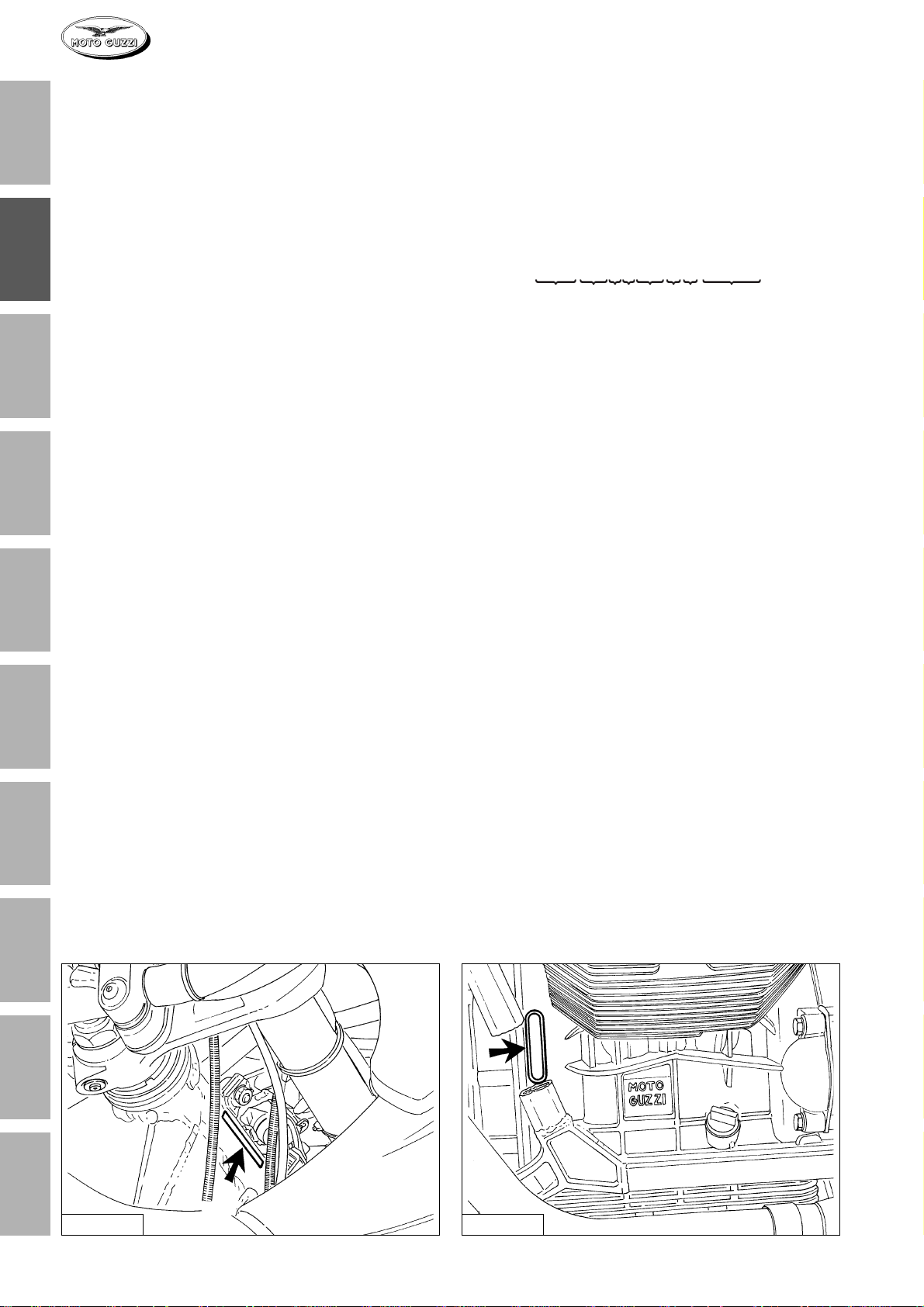
4 DATI PER L’IDENTIFICAZIONE
Ogni veicolo é contraddistinto da un numero di identificazione impresso sulla pipa del telaio e sul basamento
motore.
Il numero impresso sulla pipa del telaio é riportato sul
libretto di circolazione e serve agli effetti di legge per
l’identificazione del motociclo stesso; questo numero è
composto da cifre e lettere come nell’esempio sotto riportato.
ZGUKMA1KMWM111111
567 81234
1) Codice WMI (World Manufactures Identifier)
2) Tipo di veicolo
3) Variante
4) Ve rsione
5) Tipo di motore
6) Anno di fabbricazione variabile per esempio: W = 1998
X = 1999
Y = 2000
7) Stabilimento di produzione (M = Mandello del Lario)
8) Numero di telaio (il n° 111111 è riferito al 1° veicolo
costruito).
5
6
7
8
9
10
Fig. 02-01 Fig. 02-02
8
CARATTERISTICHE GENERALI
 Loading...