

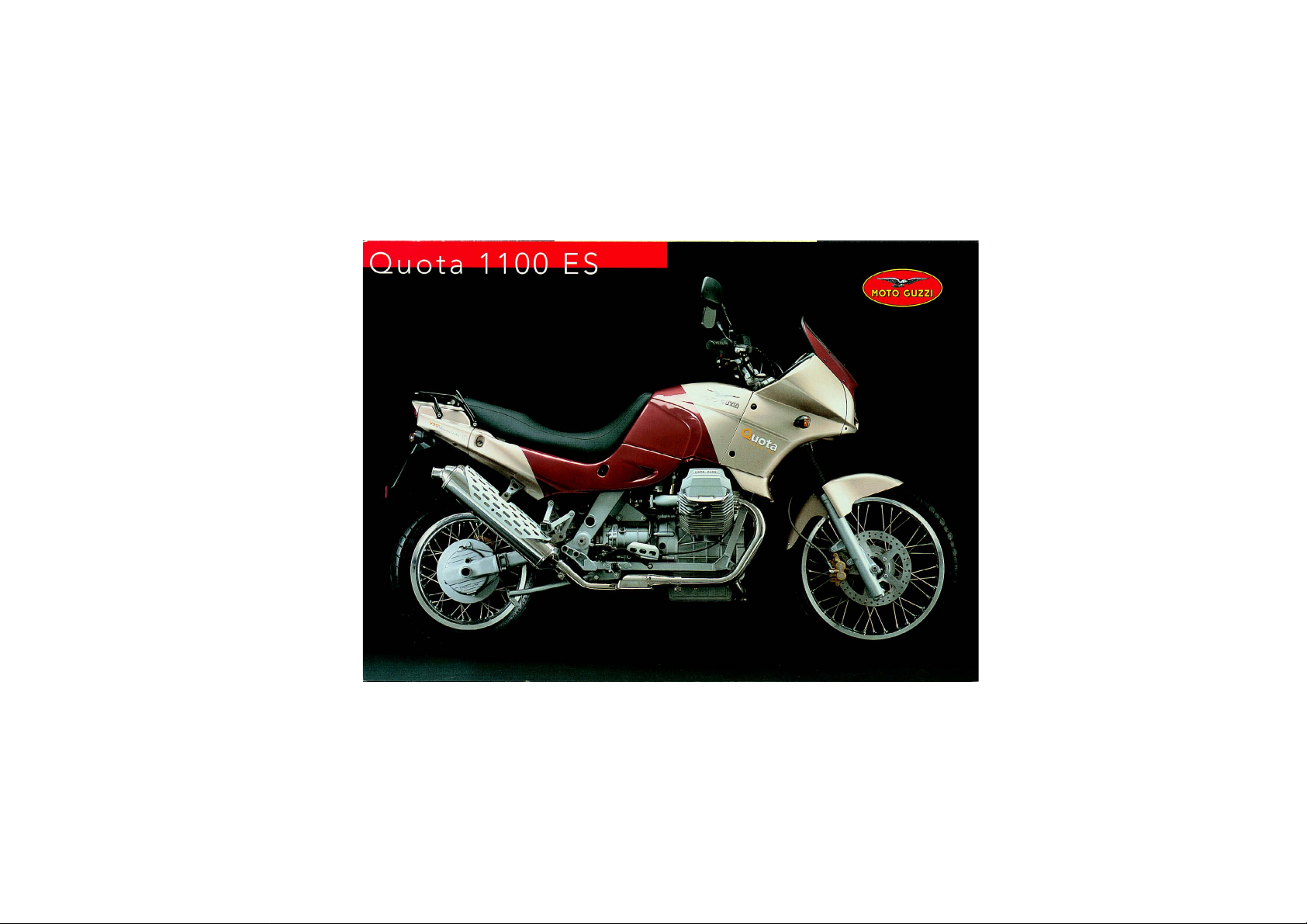
MOTO GUZZI QUOTA 1100 ES User Manual
Le illustrazioni e descrizioni di questo opuscolo si intendono fornite a titolo indicativo. La Casa si
riserva pertanto il diritto di apportare ai motocicli, in qualsiasi momento e senza avviso, quelle
modifiche che ritenesse utili per il miglioramento o per qualsiasi esigenza di carattere costruttivo
e commerciale.
The illustrations and description in this booklet are indicative only and the manufacturer reserves
itself the right to introduce any modification it may deem necessary for better performance or for
constructive or commercial reasons without prior notice.
Les illustrations et les descriptions de ce manuel s'intendent fournies à titre d'information. La
Fabrique se réserve donc le droit d'apporter aux motocycles, en tous moments et sans aucun
préavis, les modifications qu'elle estimerait utiles pour les améliorer ou pour toutes exigences
d'ordre constructif et commercial.
Die Abbildungen und Beschreibungen dieses Handbuchs sollen als praktische Hinweise dienen.
Das Werk behält sich das Recht vor, zu jedem Zeitpunkt und ohne Vorankündigung, Änderungen
am Fahrzeug, die einer konstruktiven und kommerziellen Verbesserung dienen, vornehmen zu
können.
Vendita - Assistenza - Ricambi: consultare le
MOTO GUZZI S.p.A. - Servizio Pubblicazioni Tecniche - Cod. 30 90 00 25
Printed in Italy - D.E.Ca. - Ravenna - 1000 K - 09/98

Egregio Cliente
Innanzitutto La ringraziamo per aver dato la Sua preferenza al nostro prodotto.
Seguendo le istruzioni indicate in questa pubblicazione tecnica, assicurerà alla Sua motocicletta una lunga durata senza inconvenienti.
Prima di usarla, La consigliamo di leggere completamente la presente pubblicazione al fine di conoscere le caratteristiche del veicolo
e soprattutto come manovrarlo con sicurezza.
Per le operazioni di controllo e revisione è necessario rivolgersi ai nostri concessionari i quali garantiranno un lavoro razionale e sollecito.
Riparazioni e regolazioni non effettuate durante il periodo di garanzia dalla nostra rete di assistenza potrebbero annullare la garanzia
stessa.
Dear rider
First of all we wish to thank you for choosing this motorcycle of our production.
By following the instructions outlined in this manual you will ensure your bike a long and troublefree life.
Before riding, please read thoroughly this manual in order to know your motorcycle's features and how to operate it safely.
All major checking and overhaul jobs are best carried out by our dealers who have the necessary facilities to quickly and competently
repair your Moto Guzzi.
Repairs or adjustments by any other than a Guzzi dealer during the warranty period could invalidate the warranty right.
Monsieur;
Avant tout noux vous remercions d'avoir choisi notre produit.
En suivant les renseignements portés dans ce manuel technique, Vous pourrez assurer à Votre moto une très longue durée sans
aucun inconvénient.
Avant de la mettre en marche, nous vous suggérons de lire complètement cette pubblication dans le but de connaître les
caractéristiques du véhicule et tout particulièrement le moyen pour sa utilisation en sécurité.
Pour les opérations de contrôle et de revision il faut s'addresser à nos Concessionaires qui pourront garantir un travail ratiónnel dans
le plus bref délai.
Des réparations et réglages non effectués pendant la période de garantie par notre raiseau de Stations-Service pourront annuler
la même garantie.
Zunächst danken wir Ihnen für den Vorzug, den Sie unserem Produkt eingeräumt haben.
Für eine lange Lebensdauer ohne Störungen dieses Fahrzeugs empfehlen wir Ihnen, sich an die in diesem Handbuch angegebenen
Richtlinien und Anweisungen zu halten.
Vor dem Fahren lesen Sie sich bitte diese Ausgabe genau durch, um die technischen Merkmale des Fahrzeugs kennenzulernen,
vor allem aber, um es sicher lenken zu können.
Bei Kontrollen und Überholungsarbeiten wenden Sie sich bitte an einen unserer Vertragshändler, der Ihnen eine genaue und
schnelle Arbeit garantieren wird.
Reparaturen und Einstellungen, die während der Garantiezeit nicht von unserem Kundendienst vorgenommen werden, können den
Verlust des Garantieanspruchs zur Folge haben.
IMPORTANTE - Allo scopo di rendere la lettura di immediata comprensione i paragrafi sono stati contraddistinti da
illustrazioni schematiche che evidenziano l’argomento trattato.
In questo manuale sono state riportate note informative con significati particolari:
Norme antinfortunistiche per l’operatore e per chi opera nelle vicinanze.
Esiste la possibilità di arrecare danno al veicolo e/o ai suoi componenti.
Ulteriori notizie inerenti l’operazione in corso.
IMPORTANT - The text is supplemented with schematic illustrations for quick reference and better understanding
of the subjects concerned.
This manual contains some special remarks:
Accident prevention rules for the mechanic and for the personnel working nearby.
Possibility of damaging the motorcycle and/or its components.
Additional information concerning the job being carried out.

IMPORTANT- Pour permettre une lecture plus compréhensible, les paragraphes sont accompagnés d’illustrations
schématiques qui mettent en évidence l’argument traité.
Ce manuel contient des notes informatives aux significations spéciales:
Normes de prévention contre les accidents pour l’opérateur et pour ceux qui travaillent à proximité.
Possibilité d’endommager le véhicule et/ou ses organes.
Notes complémentaires concernant l’opération en cours.
WICHTIG- Zum schnelleren Verständnis wurden die verschiedenen Paragraphen durch Abbildungen vervollständigt,
die das behandelte Argument in der Vordergrund stellen.
Dieses Handbuch enthält Informationen von besonderer Bedeutung:
Unfallverhütungsnormen für die am Motorrad arbeitende und die in der Nähe arbeitenden Personen.
Es besteht die Möglichkeit das Motorrad und/oder seine Bestandteile zu beschädigen.
Weitere Informationen für den laufenden Arbeitsvorgang.

INDICE
6 Caratteristiche
generali
18 Dati di
identificazione
22 Apparecchi di
controllo e comandi
44 Uso del motociclo
50 Rodaggio
54 Manutenzioni e
regolazioni
68 Smontaggio ruote
dal veicolo
76 Programma di
manutenzione
80 Pulizia -
rimessaggio
84 Norme per la pulizia
del parabrezza
86 Lubrificazioni
100 Distribuzione
104 Sistema iniezione-
accensione WEBER
(I.A.W. 15M)
124 Impianto elettrico
136 Schema impianto
elettrico
CONTENTS
9 Specifications
18 Frame and engine
numbers
22 Instruments and
controls
44 Riding your
motorcycle
51 Running-in
54 Maintenance and
adjustments
68 Wheel removal
77 Service schedule
80 Cleaning - storing
84 Cleaning the
windscreen
86 Lubrication
100 Valve gear
104 WEBER injection-
ignition system
(I.A.W. 15M)
124 Electrical equipment
137 Wiring diagram
INDEX
12 Caractéristiques
générales
19 Numéros
d’identification
23 Appareils de
contrôle et
commande
45 Utilisation du
motocycle
52 Rodage
55 Entretien et
réglages
69 Depose des roues
78 Programme
d’entretien
81 Nettoyage-longue
inactivité
85 Nettoyage du pare-
brise
87 Graissages
101 Distribution
105 Systeme injection-
allumage WEBER
(I.A.W. 15M)
125 Installation
électrique
138 Schema installation
electrique
INHALTSANGABE
15 Allgemeine Daten
19 Kennzeichnungen
23 Kontrollgeräte und
Antriebe
45 Gebrauchsanleitung
des Motorrades
53 Einfahren
55 Wartungen und
Einstellungen
69 Ausbau der Räder
vom Fahrzeug
79 Wartungsprogramm
81 Reinigung-
schuppen
85 Anweisungen zur
Reinigung der
Windschutzscheibe
87 Schmierarbeiten
101 Ventiltrieb
105 Zündung-
Einspritzsystem
WEBER (I.A.W. 15M)
125 Elektrische Anlage
139 Stromlaufplan
5

CARATTERISTICHE GENERALI
6
Motore
Bicilindrico a 4 tempi
Disposizione cilindri .................................a «V» di 90°
Alesaggio ......................................................... mm 92
Corsa ............................................................... mm 80
Cilindrata totale...............................................cc 1064
Rapporto di compressione.................................. 9,5:1
Coppia massima .... Nm 85 (kgm 8,7) a 3800 giri/min.
Potenza massima ...... Kw 51 (CV 70) a 6400 giri/min.
Distribuzione
Ad aste e bilancieri e 2 valvole per cilindro. Un albero a
camme nel basamento comandato da catena duplex
con tendicatena automatico.
Alimentazione
Iniezione elettronica indiretta, sequenziale fasata MAGNETI MARELLI IAW 15 M sistema “Alfa-N”, gruppo
farfallato unico, iniettori Weber IW031, pompa elettrica
con regolatore di pressione, gestione digitale dei tempi
di iniezione ottimizzata.
Lubrificazione
Sistema a pressione con pompa ad ingranaggi.
Filtri a rete ed a cartuccia montati nella coppa del
basamento.
Pressione normale di lubrificazione kg/cmq 3,8÷4,2
(regolata da apposita valvola montata nella coppa del
basamento).
Trasmettitore elettrico per segnalazione insufficiente
pressione situato sul basamento.
Generatore alternatore
Montato sulla parte anteriore dell’albero motore.
Potenza di uscita: 350W a 5000 giri/min. (14V - 25A).
Accensione
Elettronica digitale a scarica induttiva “MAGNETI
MARELLI”.
Candele di accensione: .................... NGK BPR 6 ES.
Distanza tra gli elettrodi delle candele:.......... mm 0,7.
Bobine di accensione: ............. n.2 montate sul telaio.
Avviamento
Elettrico mediante motorino avviamento (12 V - 1,2 KW)
munito di innesto a comando elettromagnetico. Corona
dentata fissata al volano motore.
Comando a pulsante (START) «
destro del manubrio.
» posto sul lato

Trasmissioni
Frizione
Tipo a secco a due dischi condotti. E’ posta sul volano
motore. Comando mediante leva sul manubrio (lato
sinistro).
Trasmissione primaria
Ad ingranaggi elicoidali, rapporto 1:1,3529 (Z=17/23).
Telaio
A doppia trave di sezione rettangolare in acciaio a
doppia culla scomponibile.
Sospensioni
Anteriore: forcella telescopica idraulica MARZOCCHI.
Posteriore: forcellone oscillante a sezione rettangolare variabile con monoammortizzatore regolabile SACHS-BOGE.
7
Cambio
A cinque marce con ingranaggi sempre in presa ad
innesto frontale. Parastrappi incorporato.
Comando con leva a pedale posta sul lato sinistro del
veicolo.
Rapporti cambio:
1ª marcia = 1:2 (Z=14/28)
2ª marcia = 1:1.3158 (Z=19/25)
3ª marcia = 1:1 (Z=23/23)
4ª marcia = 1:0,8462 (Z=26/22)
5ª marcia = 1:0,7308 (Z=26/19)
Trasmissione secondaria
Ad albero con giunto cardanico ed ingranaggi.
Rapporto: 1:4,125 (Z=8/33)
Rapporti totali (motore-ruota):
1ª marcia = 1:11,1618
2ª marcia = 1: 7,3433
3ª marcia = 1: 5,5809
4ª marcia = 1: 4,7223
5ª marcia = 1: 4,0783
Ruote
A raggi con cerchi in alluminio:
– anteriore: 1,85" x 21"
– posteriore: 2,75" x 17"
Pneumatici
– anteriore: 90/90 - 21 54H
– posteriore: 130/80 - R17 65H
Freni
Anteriore: due dischi fissi con pinza flottante a due
pistoncini paralleli. Comando con leva a mano posta sul
lato destro del manubrio.
– Ø disco 296 mm;
– Ø cilindro frenante 30/32 mm;
– Ø pompa 16 mm.
Posteriore: a disco con pinza flottante a due pistoncini
paralleli. Comando con leva a pedale posta al centro sul
lato destro del veicolo;
– Ø disco 260 mm;
– Ø cilindro frenante 28 mm;
– Ø pompa 13 mm.
Ingombri e peso
8
Passo (a carico)............................................. m 1,600
Lunghezza massima...................................... m 2,260
Larghezza massima ...................................... m 0,935
Altezza massima (parabrezza) ...................... m 1,355
Altezza minima da terra ................................. m 0,170
Peso (a secco)................................................. kg 245
Prestazioni
Velocità massima con il solo pilota a bordo senza
accessori: 190 Km/h.
Consumo carburante: litri 4,9 per 100 km (norme CUNA).
N.B. - Il motoveicolo può essere equipaggiato
a richiesta con borse asportabili di notevole
capacità.
Tutti questi volumi comportano però una limitazione all’aerodinamica del veicolo. E’ consigliabile
pertanto, specie in condizioni di carico massimo,
non superare la velocità di 130 Km/h circa.
Rifornimenti
erinrofiraditraPirtiLerageipmiadittodorP
erotomappoC3
oibmacalotacS057,0
enoissimsartalotacS
)acinocaippocenoizacifirbul(
)acric4tlavresir(etnarubracoiotabreS.ac02).nim/MR-ON79(repusanizneB
052,0
iucid
032,0
020,0
)abmagrep(acipocseletallecroF565,0)5,7EAS(irotazzitrommarepoilO
eroiretsopeeroiretnaetnanerfotnaipmI—»4TOD-diulFekarBpigA«odiulF
»09/W08EASPMartoRpigA«oilO
»09/W08EASPMartoRpigA«oilO
»R/OSAlocoRpigA«oilO
»AopitetokyloM«eruppo
).nim/MR-ON59(obmoipaznesanizneB
»05/W02EASGNICARREPUST4pigA«oilO

SPECIFICATIONS
Engine
4-stroke, twin cylinder
Cylinder configuration .................................90° V-twin
Bore: ................................................................ 92 mm
Stroke:.............................................................. 80 mm
Capacity: .........................................................1064 cc
Compression ratio:.............................................. 9.5:1
Max. torque: ................. Nm 85 (kgm 8,7) at 3800 rpm
Max. power: ................Kw 51 (CV 70) a 6400 rev/min
Timing system
With rods and rockers and 2 valves per cylinder. One
camshaft in the crankcase driven by duplex chain with
automatic chain tensioner.
Feed system
Indirect electronic injection, timed sequential MAGNETI
MARELLI IAW 15M “Alfa-N” system, single throttlebody, Weber IW031 injectors, electric pump with pressure regulator, digital control of optimised injection times.
Lubrication
Pressure fed by gear pump.
Wire mesh and cartridge filters on oil sump.
Normal lubrication pressure 3.8÷4.2 kg/cm2 (pressure
valve on oil sump).
Low oil pressure sensor (electrical) on crankcase.
Generator / Alternator
On front of crankshaft.
Output power: 350W at 5000 rev./min. (14V - 25A).
Ignition
“MAGNETI MARELLI” Inductive discharge digital electronics.
Spark plugs: ...................................... NGK BPR 6 ES.
Spark plug gap:............................................... 0.7 mm
2 ignition coils ...............................mounted on frame.
Starter
Electric starter motor 12V-1,2 Kw with electromagnetic
ratchet control. Ring gear on the flywheel. START «
push-button on right handlebar.
9
»

Transmission
10
Clutch
Dry, twin driven plates. Located on engine flywheel.
Clutch lever on left handlebar.
Primary drive
With helical gears, 1:1.3529 (Z=17/23).
Gearbox
5-speed, front engaging, constant mesh.
Incorporated Cush drive
Control pedal on left side of machine.
Gear ratios:
1st 1:2 (Z=14/28)
2nd 1:1.3158 (Z=19/25)
3rd 1:1 (Z=23/23)
4th 1:0,8462 (Z=26/22)
5th 1:0.7308 (Z=26/19)
Final drive
Cardan shaft with gears
Ratio: 1:4,125 (Z=8/33)
Overall gear ratios (engine-wheel)
1st gear = 1:11,1618
2nd gear = 1: 7,3433
3rd gear = 1: 5,5809
4th gear = 1: 4,7223
5th gear = 1: 4,0783
Frame
Double steel rectangular bar with double cradle.
Suspension
Front: Marzocchi tele-hydraulic forks.
Rear: adjustable rectangular swinging arm with SACHSBOGE adjustable single shock absorber.
Wheels
Spoked, with aluminum rims.
– Front: 1,85"x21"
– Rear: 2,75"x17"
Tyres
– Front: 90/90-21 54H
– Rear: 130/80-R17 65H
Brakes
Front: Two fixed disks with floating caliper with two
parallel pistons. Hand lever control located on the righthand side of the handlebar.
– disk Ø 296 mm;
– braking cylinder Ø 30/32 mm;
– pump Ø 16 mm.
Rear: Disk with floating caliper with two parallel pistons.
Pedal lever control located in the centre on the righthand side of the vehicle.
– disk Ø 260 mm;
– braking cylinder Ø 28 mm;
– pump Ø 13 mm.
Dimensions and weight
Wheelbase ..................................................... 1,600 m
Overall length................................................. 2,260 m
Overall width .................................................. 0,935 m
Height (with screen)....................................... 1,355 m
mminimum height from ground...................... 0,170 m
Weight (dry) ..................................................... 245 kg
Performance
Maximum speed with rider only on board and without
accessories: 190 km/h. Fuel consumption: 4.9 litres for
100 km (CUNA standards).
N.B. - On request the motor vehicle can be
equipped with a large capacity removable
sidebags.
These items do however after the aerodynamic
features of the bike; it is advisable therefore not to
exceed 130 kph especially when the bike is fully
loaded.
Refuelings
traPsertiLtcudorpdednemmocceR
pmusliO3
xobraeG057.0
evirdraeR
).bultesleveb(
)gelrof(skroftnorF565.0)5,7EAS(liosrebrosbA-kcohS
).tl4xorppaevreser(knatleuF02.xorppa).nim/MR-ON79(lorteprepuS
052.0
hcihwfo
032.0
020.0
stiucricekarbraerdnatnorF—»4TOD-diulFekarBpigA«
11
).nim/MR-ON59(lortepdedaelnU
»05/W02EASGNICARREPUST4pigA«
lio»09/W08EASPMartoRpigA«
lio»09/W08EASPMartoRpigA«
»R/OSAlocoRpigA«
»AeoytetokyloM«ro

CARACTERISTIQUES GENERALES
12
Moteur
2 cylindres à 4 temps
Disposition des cylindres ....................... en «V» à 90°
Alésage ............................................................ mm 92
Course ............................................................. mm 80
Cylindrée totale............................................... cc 1064
Rapport volumetrique ......................................... 9,5:1
Couple maxi........ Nm 85 (kgm 8,7) à 3800 tours/min.
Puissance maxi.......Kw 51 (CV 70) a 6400 tours/min.
Distribution
A tiges et culbuteurs et deux soupapes chaque cylindre.
Un arbre à cames dans le carter, actionné par la chaîne
duplex avec tendeur de chaîne automatique.
Alimentation
Injection électronique indirecte, séquentielle synchronisée MAGNETI MARELLI IAW 15M système “Alpha-N”,
groupe papillon unique, avec injecteurs Weber IW031,
pompe électronique avec régulateur de pression, gestion digitale des temps d’injection optimisée.
Graissage
Sous pression par pompe à engrenages.
Filtres à crépine et à cartouche montés dans le carter
inférieur.
Pression normale de graissage kg/cmq 3,8÷4,2 (réglable avec clapet situé dans le carter inférieur).
Monocontact sur le carter pour signaler l’abaissement
de la pression.
Alternateur
Monté à l’avant et en bout du vilebrequin.
Puissance de sortie: 350W à 5000 tours/minute (14V 25A)
Allumage
Electronique numérique à décharge inductive “MAGNETI
MARELLI”.
Bougies: ............................................ NGK BPR 6 ES.
Ecartement des électrodes:............................ mm 0,7
Bobines d’allumage: ............. 2 montées sur le cadre.
Démarrage
Démarreur électrique (12V - 1,2 KW) avec accouplement à commande électromagnétique. Couronne dentée fixée au volant-moteur. Commande par bouton
poussoir (START) «
» situé sur la droite du guidon.

Transmission
Embrayage
Embrayage à sec par deux disques entraînés, situé sur
le volant-moteur. Levier de commande sur le guidon (à
gauche).
Transmission primaire
A engrenages hélicoïdaux, rapport 1 : 1,3529 (Z=17/23).
Boîte de vitesse
A cinq rapports avec engrenages toujours en prise et
clabotage frontal. Pare-sacades incorporé.
Commande par pédale située sur le côté gauche du
véhicule.
Rapports de la boîte de vitesse:
1ère = 1:2 (Z=14/28)
2ème = 1:1,3158 (Z=19/25)
3ème = 1:1 (Z=23/23)
4ème = 1:0,8462 (Z=26/22)
5ème = 1:0,7308 (Z=26/19)
Transmission secondaire
A cardan et engrenages.
Rapport: 1:4,125 (Z=8/33)
Rapport total (moteur-roue):
1ère = 1:11,1618
2ème = 1: 7,3433
3ème = 1: 5,5809
4ème = 1: 4,7223
5ème = 1: 4,0783
Cadre
A double poutre de section rectangulaire en acier, à
double berceau démontable.
Suspensions
Avant: à fourche télé-hydraulique Marzocchi.
Arrière: bras oscillant à section rectangulaire variable
avec mono-amortisseur réglable SACHS-BOGE.
Roues
A rayons avec jantes en aluminium:
– AV: 1,85"x21"
– AR: 2,75"x17"
Pneus
– AV: 90/90-21 54H
– AR: 130/80-R17 65H
Freins
Avant : deux disques fixes avec étrier flottant à deux
pistons parallèles. Commande à levier manuel situé du
côté droit du guidon.
– Ø disque 296 mm;
– Ø cylindre freinant 30/32 mm;
– Ø pompe 16 mm.
Arrière : à disque avec étrier flottant à deux pistons
parallèles. Commande avec levier à pédale situé au
milieu, du côté droit du véhicule.
– Ø disque 260 mm;
– Ø cylindre freinant 28 mm:
– Ø pompe 13 mm.
13
Dimensions et poids
14
Empattement (chargé) ................................... m 1,600
Longueur maxi ............................................... m 2,260
Largeur maxi .................................................. m 0,935
Hauteur maxi (au pare-brise)......................... m 1,355
Hauteur minimum du sol................................ m 0,170
Poids (à sec).................................................... kg 245
Ravitaillements
rilpmeràstnemélEsertiLreyolpmeàstiudorP
ruetomretraC3
tnoP
essetivedetîoB057,0
)euqinocelpuocnoitacifirbul(
)ehcnarbrap(euqipocselétehcruoF565,0)5,7EAS(sruessitrommaruopliO
RAteVAnierfedtiucriC—»4TOD-diulFekarBpigA«ediuqiL
)sertil4norivne:evresér(ecnesseàriovreséRnorivne02).nim/MR-ON79(repusecnessE
052,0
tnod
032,0
020,0
Performances
Vitesse maximale avec uniquement le pilote à bord et
sans accessoires: 190 km/h
Consommation de carburant : 4,9 litres pour 100 km
(normes CUNA).
N.B. - Le motocycle peut être équipé sur
demande de sacs que l’on peut emporter
d’une grande capacité.
Cependant, ces éléments diminuent les caractéristiques aérodynamiques du véhicule. Il est
conseillable, spécialment en conditions de charge
maximal, de ne pas dépasser la vitesse de 130 km/
h environ.
).nim/MR-ON59(bmolpsnasecnessE
»05/W02EASGNICARREPUST4pigA«eliuH
»09/W08EASPMartoRpigA«eliuH
»09/W08EASPMartoRpigA«eliuH
»R/OSAlocoRpigA«eliuH
»AepytetokyloM«uo

ALLGEMEINE DATEN
Motor
Viertakt-Motor mit 2 Zylindern
Zylinderanordnung:............................................ V 90°
Bohrung: .......................................................... 92 mm
Hub: ................................................................. 80 mm
Hubraum: ........................................................ 1064 cc
Verdichtungsverhältnis: ...................................... 9,5:1
Max. Drehmoment: Nm 85 (kgm 8,7) bei 3800 U/min.
Max. Leistung: ............. Kw 51 (CV 70) a 6400 U/min.
Steuersystem
Über Stangen und Kipphebel und 2 Ventile pro Zylinder.
Eine Nockenwelle im Gehäuse, die über eine DuplexKette mit automatischen Kettenspanner gesteuert wird.
Kraftstoffversorgung
Indirekte ektronische Einspritzung, sequentiell und
phasengleich, MAGNETI MARELLI IAW 15M, System
“Alfa-N”, einzelne drosselgruppe, Einspritzventilen
IW031, Elektropumpe mit Druckregler, optimierte digitale Steuerung der Einspritztakte.
Schmierung
Drucksystem durch Zahnradpumpe. Netz- und Patronefilter in der Motorölwanne montiert.
Normaler Schmierdruck 3,8 - 4,2 Kg/cmq. (Einstellventil
in der Ölwanne montiert).
Elektrischer Öldruckgeber, Anzeiger für ungenügenden
Druck.
Lichtmaschine/Alternator
Vorne auf der Kurbelwelle montiert.
Ausgangsleistung: 350 W bei 5.000 U/Min. (14V - 25A).
Zündung
Digital gesteuerte Elektronik mit induktiver Entladung
“MAGNETI-MARELLI”.
Zündkerzen: ...................................... NGK BPR 6 ES.
Elektrodenabstand der Kerzen: ...................... 0,7 mm
Zündspulen: .................. 2 Stk., am Rahmen montiert.
Anlasssystem
Elektrischer Anlassmotor (12V-1,2 KW) mit magnetgesteuerter Kupplung. Zahnkranz am Schwungrad befestigt.
Anlasserknopf (START) «
Lenkers.
» auf der rechten Seite des
15

Kraftübertragung
16
Kupplung
Zweischeiben-Trockenkupplung. Sie befindet sich auf
dem Schwungrad. Durch Handhebel auf der linken
Seite des Lenkers betätigt.
Primärtrieb
Mit Schrägzahnrädern, Verhältnis 1:1,3529 (Z=17/23)
Getriebe
5-Gang, Zahnräder im ständigen Eingriff. Eingebaute
elastische Kupplung. Schaltpedal an linker Fahrzeugseite. Getriebeverhältnisse:
1. Gang = 1:2 (Z = 14/28)
2. Gang = 1:1,3158 (Z = 19/25)
3. Gang = 1:1 (Z = 23/23)
4. Gang = 1:0,8462 (Z = 26/22)
5. Gang = 1:0,7308 (Z = 26/19)
Sekundärtrieb
Welle mit Kardangelenk und Zahnräder.
Verhältnis: 1:4,125 (Z=8/33)
Gesamt-Verhältnisse (Motor - Rad):
1. Gang = 1:11,1618
2. Gang = 1: 7,3433
3. Gang = 1: 5,5809
4. Gang = 1: 4,7223
5. Gang = 1: 4,0783
Rahmen
Mit Doppel-Stahlträger mit Rechteckschnitt und doppelter zerlegbarer Wiege.
Federung
Vorne: mit telehydraulischer Marzocchi Gabel.
Hinten: mit Schwinggabel mit veränderlichem Rechteckschnitt und einstellbarem SACHS-BOGE Einzeldämpfer.
Räder
Speichenräder mit Alufelgen.
– Vorne: 1,85"x21"
– Hinten: 2,75"x17"
Reifen
– Vorne: 90/90-21 54H
– Hinten: 130/80-R17 65H
Bremsen
Vorderradbremse: zwei feste Scheiben mit beweglich
eingehängtem Sattel und 2 parallelen Steuerkolben.
– ø der Scheibe 296 mm;
– ø des Bremszylinders 30/32 mm;
– ø der Pumpe 16 mm;
Hinterradbremse: Scheibenbremse mit beweglich
eingehängtem Sattel und 2 parallelen Steuerkolben.
Steuerung mit Pedalhebel in der Mitte an der rechten
Motorradseite;
– ø der Scheibe 260 mm;
– ø des Bremszylinders 28 mm;
– ø der Pumpe 13 mm;
Masse und Gewichte
Achsabstand (belastetes Fahrzeug).............. 1,600 m
Max. Länge .................................................... 2,260 m
Max. Breite..................................................... 0,935 m
Max. Höhe (Windschutzscheibe)................... 1,355 m
Mindestabstand vom boden .......................... 0,170 m
Leergewicht ..................................................... 245 kg
Leistungen
Höchstgeschwindigkeit nur mit dem Fahrer und ohne
Zubehör: 190 km/h.
Kraftstoffverbrauch: 4,9 Liter auf 100 km (CUNA-Normen).
MERKE - Das Fahrzeug kann bei Bedarf mit
leistungsfähigen, abnehmbaren Gepäck-
taschen ausgerüstet werden. Alle diese Volumen
bringen aber zur Beschränkung der Aerodynamik
des Fahrzeugs. Wir empfehlen deshalb, vor allem
im Höchstbelastungs-zustand die ca. 130 km/h nicht
zu überschreiten.
17
Kraftstoff- und schmiermittelversorgung
elietsgnugrosreVretiLnepytlÖdnu-nizneB
ennawlÖ3
esuähegebeirteG057,0
esuähegsbeirtnA
)mloHeJ(lebagpokseleT565,0)5,7EAS(refpmadßotSrüflÖ
).L4.acevreseR(retlähebffotstfarK.ac02).nim/MR-ON79(repuSnizneB
)seraaplegeKsedgnureimhcS(
netnihdnuenrov,regalnasmerB—»4TOD-diulFekarBpigA«lÖ
052,0
novad
032,0
020,0
).nim/MR-ON59(ierfielBnizneB
»05/W02EASGNICARREPUST4pigA«lÖ
»09/W08EASPMartoRpigA«lÖ
»09/W08EASPMartoRpigA«lÖ
»R/OSAlocoRpigA«lÖ
»ApyTetokyloM«redo
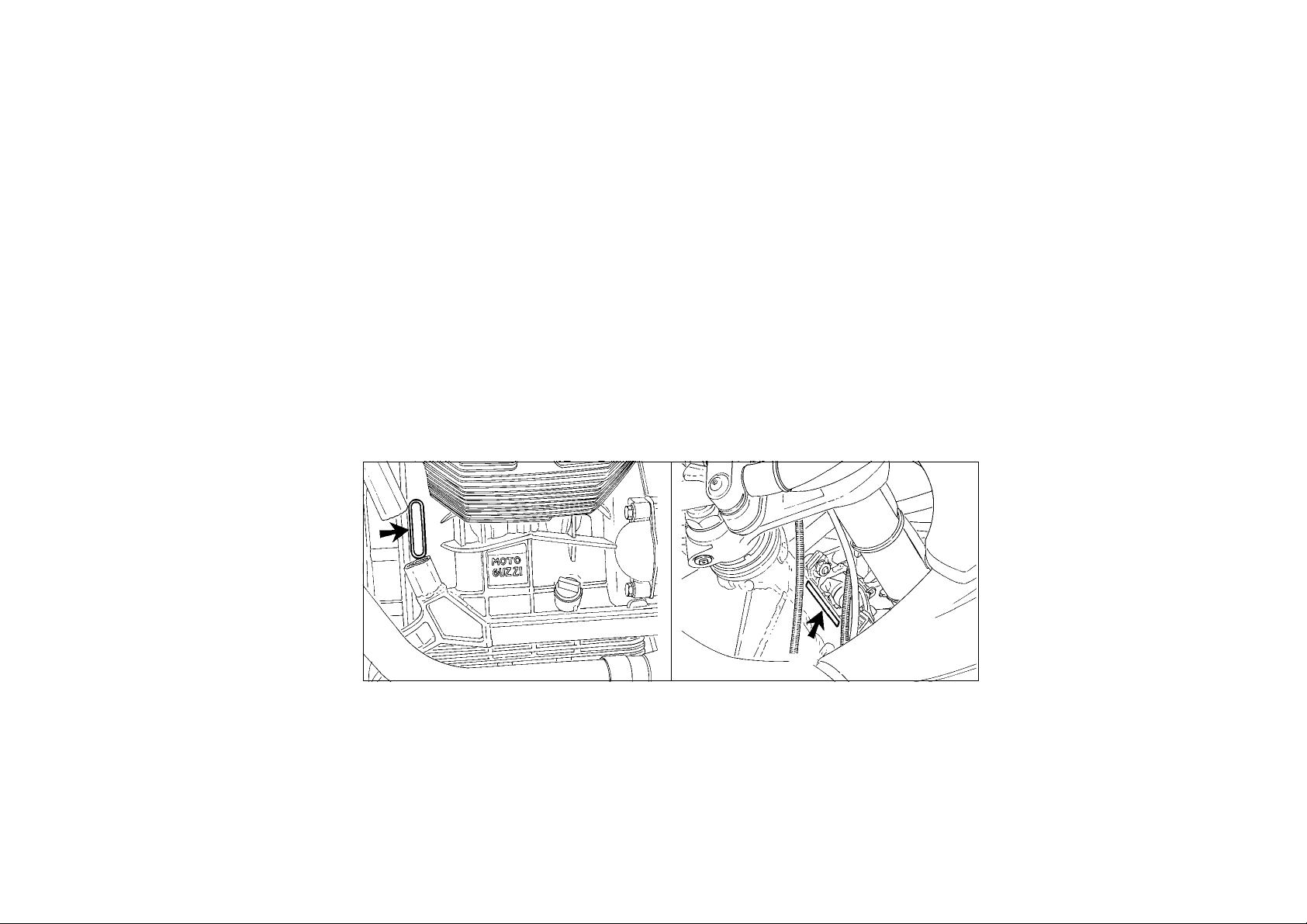
DATI DI IDENTIFICAZIONE (fig. 2)
18
Ogni veicolo è contraddistinto da un numero di identificazione impresso sulla pipa del telaio, e sul basamento
motore.
Il numero impresso sulla pipa del telaio è riportato sul
libretto di circolazione e serve agli effetti di legge per
l’identificazione del motociclo stesso.
FRAME AND ENGINE NUMBERS (fig. 2)
Each vehicle is stamped with an identification number
on the tubular frame, and on the crankcase.
The number stamped on the tubular frame is written in
the motorcycle logbook and is the vehicle’s legal identification.
2

NUMEROS D’IDENTIFICATION (fig. 2)
Chaque véhicule possède par un numéro d’identification gravé sur la potence du cadre, et sur le carter
moteur.
Le numéro gravé sur la potence du cadre est rapporté
sur la carte de circulation; il a une valeur légale lors de
l’identification du véhicule.
KENNZEICHNUNGEN (Abb. 2)
Jedes Fahrzeug ist durch eine auf dem Gestell-Lenkrohr, und auf dem Motorgehäuse eingeprägte Seriennummer gekennzeichnet.
Die auf dem Gestell-Lenkrohr eingeprägte Seriennummer ist auf dem Kraftfahrzeugbrief angegeben und
dient zur gesetzmäßigen Identifizierung des Motorrads.
19

Ricambi
20
In caso di sostituzione di particolari, chiedere ed assicurarsi che siano impiegati esclusivamente «Ricambi
Originali Moto Guzzi».
L’uso di ricambi non originali annulla il diritto alla
garanzia.
Spare Parts
Always use approved «Moto Guzzi Original Spares»
only when replacing or repairing parts.
Use of spares which are not approved will invalidate
warranty rights.

Pièces détachées
En cas de remplacement de pièces, il faut exiger
l’emploi exclusif de «Pièces d’origine Moto Guzzi».
L’utilisation de pièces non d’origine vous ferait
perdre le bénéfice de la garantie.
Ersatzteile
Im Falle eines Austausches von Ersatzteilen verlangen
und versichern Sie sich, dass nur «Original Moto Guzzi
Ersatzteile» verwendet werden, andernfalls wird
keine Garantie gewährleistet.
21
APPARECCHI DI CONTROLLO E
22
COMANDI
INSTRUMENTS AND CONTROLS
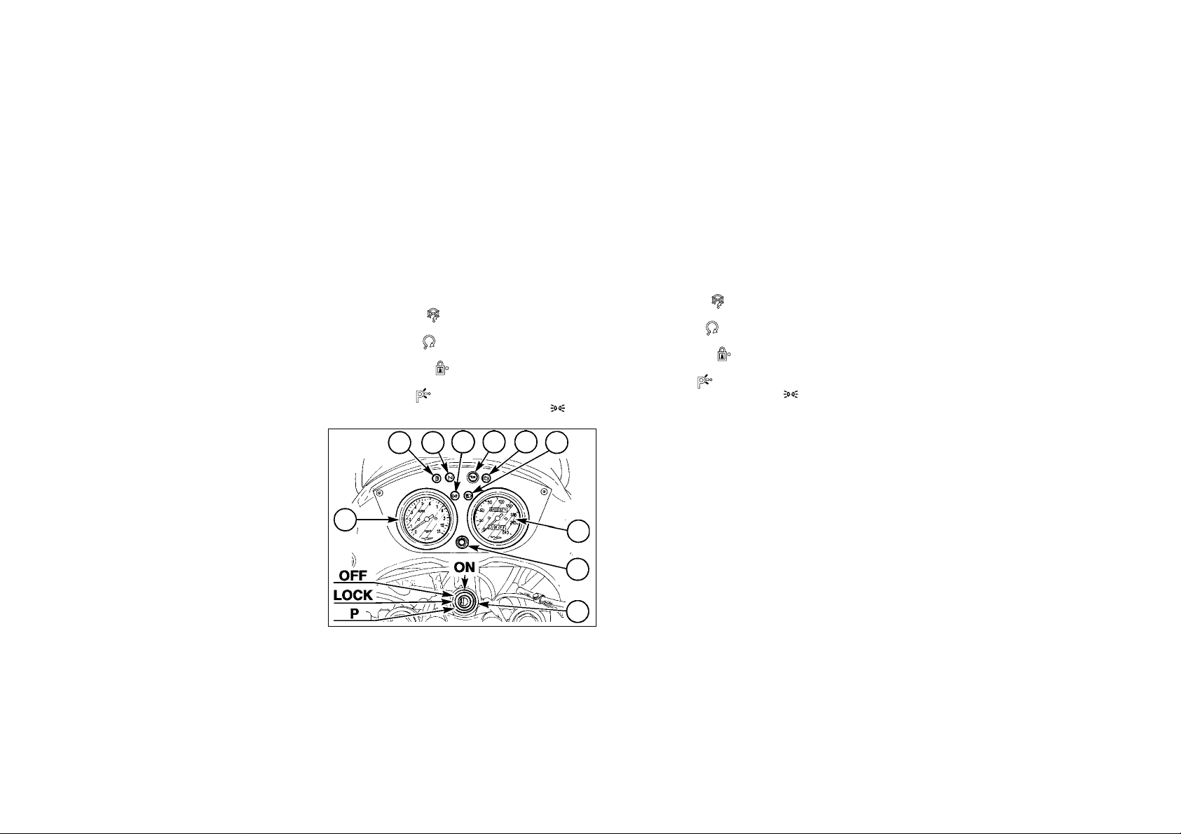
Quadro di controllo (fig. 3)
1 Commutatore a chiave per inserimento utilizzatori e
bloccasterzo.
Posizione OFF « » veicolo fermo. Chiave estraibile
(nessun contatto);
Posizione ON « » veicolo pronto per l’avviamento.
Tutti gli utilizzatori sono inseriti. Chiave non estraibile;
Posizione LOCK « » sterzo bloccato. Motore spen-
to, nessun contatto, chiave estraibile.
Posizione P « » sterzo bloccato. Motore spento;
con l’interruttore «A» di fig. 4 in posizione « » si ha
la luce di parcheggio. Chiave estraibile.
6
5
10
4
978
2
3
1
Control panel (fig. 3)
1 Key switch for devices and steering lock.
Position OFF « » vehicle stationary. Key remov-
able (no contact).
Position ON « » vehicle ready to be started.
All circuits are on. Key not removable.
Position LOCK « » steering locked. Engine off, no
contact, key removable.
Position P « » steering locked. Engine off; with
switch «A» of fig. 4 in position « » the parking light
is on. Key removable.
3
APPAREILS DE CONTROLE ET
COMMANDE
KONTROLLGERÄTE UND ANTRIEBE
23
Tableau de bord (fig. 3)
1 Commutateur à clé pour alimentation des acces-
soires et antivol.
Position OFF « » véhicule à l’arrêt. La clé peut
être enlevée (pas de contact);
Position ON « » véhicule prêt à démarrer.
Tous les accessoires sont alimentés. Clé non extractible;
Position LOCK « » direction bloquée. Moteur
éteint, pas de contact, clé extractible.
Position P « » direction bloquée. Moteur éteint;
interrupteur «A» de la fig. 4 à la position « »: feu
de parking. Clé extractible.
Instrumentenbrett (Abb. 3)
1 Schlüsselschalter zur Aktivierung der Verbraucher
und des Lenkschlosses.
« »OFF-Stellung: stehendes Fahrzeug. Heraus-
ziehbarer Schlüssel (kein Kontakt).
« » ON-Stellung: startbereites Fahrzeug.
Sämtliche Verbraucher sind eingeschaltet. Der
Schlüssel läßt sich nicht ausziehen.
« »LOCK-Stellung: Lenkung nach links gesperrt.
Motor aus: kein Kontakt, herausziehbarer Schlüssel.
« » P-Stellung: Lenkung gesperrt. Motor abgeschaltet; mit dem auf der Abb. 4 dargestellten Schalter «A» auf der Position « » wird das Parklicht
eingeschaltet. Der Schlüssel ist ausziehbar.
24
Per azionare il dispositivo bloccasterzo operare come
segue:
■ Ruotare il manubrio verso sinistra.
■ Premere la chiave verso il basso e rilasciarla,
quindi ruotarla in senso antiorario sino alla posizione
LOCK « » o P « ».
ATTENZIONE: non girare la chiave in posizione LOCK « » o P « » durante la marcia.
2 Tachimetro contachilometri.
3 Azzeratore per contachilometri parziale.
4 Contagiri.
5 Spia (luce verde) «Neutral» indicatore cambio in
folle. Si accende con il cambio in folle.
6 Spia (luce verde) per lampeggiatori.
7 Spia (luce bleu) luce abbagliante.
8 Spia (luce rossa) pressione olio. Si spegne quando
la pressione è sufficiente ad assicurare la lubrificazione del motore. Se la spia non si spegne, la
pressione non è quella prescritta; in tal caso, occorre
fermare immediatamente il motore ed effettuare le
opportune ricerche.
9 Spia (luce rossa) erogazione corrente del generato-
re. Si deve spegnere appena il motore ha raggiunto
un certo numero di giri.
10 Spia (luce arancio) riserva carburante.
In order to use the steering lock mechanism, proceed
as follows:
■ Turn the handlebars to the left.
■ Press the key downwards and release it, then
turn it in an anticlockwise direction to the LOCK « »
or P « » position.
WARNING: Never turn the key to position
LOCK « » or P « » when the engine is
running.
2 Odometer, tachometer.
3 Partial rev counter zeroing
4 Rev counter.
5 Pilot light (green) «Neutral» for neutral position.
Lights up when the gearbox is in neutral.
6 Pilot light (green) for flashing indicators.
7 Pilot light (blue) for main beam.
8 Oil pressure pilot light (red). Goes out when the oil
pressure is sufficient to ensure engine lubrication. If
the pilot light doesn’t go out, then the pressure is not
at the required level; in this case, stop the engine
immediately and check the fault.
9 Pilot light (red) for generator current output. Should
go out when the engine reaches a certain number of
revs.
10 Petrol tank reserve pilot light (orange).
Pour actionner le dispositif antivol, suivre les indications ci-dessous:
■ Tourner le guidon vers la gauche.
■ Presser la clé vers le bas, relâcher et la tourner
ensuite dans le sens inverse des aiguilles d’une
montre jusqu’à la position LOCK « » ou P « ».
ATTENTION: en cours de marche, ne faire
tourner la clé ni à la position LOCK « »
ni à la position P « ».
2 Compteur
3 Remise à zéro pour compteur partiel
4 Compte-tours
5 Témoin (lumière verte) «neutre» indicateur change-
ment de vitesse au point mort. S’allume lorsque le
levier de vitesse est au point mort.
6 Témoin (lumière verte) pour clignotants.
7 Témoin (lumière bleu) feu de route.
8 Témoin (lumière rouge) pression de l’huile. S’éteint
lorsque la pression suffit pour assurer la lubrification
du moteur. Si le témoin ne s'éteint pas, cela indique
que la pression n'est pas à la valeur prescrite. Dans
ce cas, il faut aussitôt arrêter le moteur et effectuer
les contrôles utiles.
9 Témoin (lumière rouge) distribution de courant du
générateur. Doit s’éteindre dès que le moteur a
atteint un certain nombre de tours.
10 Témoin (lumière orange) réserve carburant.
Zur Aktivierung des Lenkschlosses wie folgt vorgehen:
■ Den Lenker nach links drehen.
■ Den Schlüssel nach unten drücken und wieder
loslassen. Dann gegen den Uhrzeigersinn bis zur
Position LOCK « » oder P « » drehen.
ACHTUNG: Auf keinen Fall den Schlüssel
während der Fahrt auf LOCK « » oder P
« » stellen.
2 Tachometer Kilometerzähler.
3 Rücksteller für Tageskilometerzähler.
4 Drehzahlmesser
5 (grüne) «Neutral» Kontrolleuchte: Neutralstellungs-
anzeige. Leuchtet bei der Neutralstellung des Getriebes auf.
6 (grüne) Kontrolleuchte Blinker.
7 (blau) Kontrolleuchte Fernlicht.
8 (rote) Öldruckkontrolleuchte. Erlischt wenn der Druck
zur Motorschmierung ausreicht. Wenn die Kontrolleuchte nicht erlischt, entspricht der Druck dem vorgeschriebenen Wert nicht. In diesem Fall ist der
Motor sofort abzustellen und die entsprechende
Ursache zu suchen.
9 (rote) Kontrolleuchte: Stromversorgung vom Gene-
rator. Diese Kontrolleuchte muß beim Erreichen
einer bestimmten Motordrehzahl erlöschen.
10 (orangenfarbige) Kontrolleuchte: Kraftstoff-Reser-
ve.
25
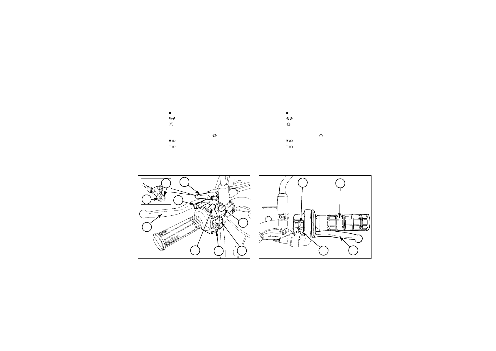
Interruttori comando luci (fig. 4)
26
Sono montati sul lato sinistro del manubrio.
Interruttore «A»
■ Posizione « » luci spente.
■ Posizione « » luci di parcheggio.
■ Posizione « » accensione lampada biluce.
Interruttore «B»
Con l’interruttore «A» in posizione « ».
■ Posizione « » luce anabbagliante.
■ Posizione « » luce abbagliante.
Light switches (fig. 4 )
These switches are on the left handlebar.
Switch «A»
■ Position « » lights off.
■ Position « » parking lights on.
■ Position « » twin-filament headlamp on.
Switch «B»
With switch «A» in position « ».
■ Position « » dipped beam.
■ Position « » main beam.
1
2
F
C
G
A
E
4
A
C
B
D
5
B
D

Interrupteurs de commande feux (fig. 4)
Ils sont montés sur les côtés du guidon.
Interrupteur «A»
■ Position « » feux éteints.
■ Position « » feux de stationnement allumés.
■ Position « » lampe bilux allumée.
Interrupteur «B»
Avec l’interrupteur «A» sur la position « ».
■ Position « » feu de croisement.
■ Position « » feu de route.
Schalter für Beleuchtung (Abb. 4)
Sie befinden sich an den Lenkungsseiten.
Schalter «A»
■ Stellung « »: Licht aus.
■ Stellung « »: Parklicht
■ Stellung « »: Zweilichtlampe eingeschaltet
Schalter «A»
Mit Schalter «A» (lights) in Stellung « »:
■ Stellung « » Abblendlicht
■ Stellung « » Fernlicht
27
Pulsante per avvisatore acustico,
28
passing e interruttore comando lampeggiatori (fig. 4)
Sono montati sul lato sinistro del manubrio:
Pulsante E « » comando avvisatore acustico.
Pulsante C « » comando luce a sprazzo.
Pulsante «D».
■ Posizione « » comando lampeggiatori destri.
■ Posizione « » comando lampeggiatori sinistri.
■ Premere l’interruttore per disinserire i lampeggiatori.
Horn Button, Headlamp Flasher and
direction indicators (fig. 4)
These are mounted on the left handlebar:
Push-button E « » sounds the electric horn when
pressed.
Push-button C « » flashing light control.
Push-button «D».
■ Position « » for right turn signals control.
■ Position « » for left turn signals control.
■ Press the switch to disconnect flashers.
Leva comando «Choke» («F» di fig. 4)
La leva comando dispositivo di avviamento a motore
freddo (CHOKE) è situata sul lato sinistro del manubrio:
■ «1» posizione di avviamento.
■ «2» posizione di marcia.
Leva comando frizione («G» di fig. 4)
E’ situata sul lato sinistro del manubrio; va azionata solo
alla partenza e durante l’uso del cambio.
Pulsante avviamento e levetta di fermo motore (fig. 5)
Sono montati sul lato destro del manubrio.
Con chiave «1» di fig. 3 in posizione ON « », il veicolo
è pronto per l’avviamento.
Per avviare il motore operare come segue:
«Choke» control («F» in fig. 4)
The «CHOKE» is on the left handlebar and is used for
cold starts.
■ Position «1» CHOKE on; starting position.
■ Position «2» CHOKE off; engine running.
Clutch lever («G» in fig. 4)
This is on the left handlebar and is only to be used when
starting or changing gear.
Starter Button and Engine Stop Lever
(fig. 5)
These are mounted on the right handlebar.
With the key «1» in fig. 3 in position ON « », the vehicle
is ready for starting.
To start the engine:
Bouton klaxon, appels de phare et
interrupteur clignotants (fig. 4)
Ils sont montés sur le côté gauche du guidon:
Bouton E « » commande klaxon électrique
Bouton C « » commande d’appels de phare.
Bouton «D».
■ Position « » commande clignotants droits.
■ Position « » commande clignotants gauches.
■ Pousser l’interrupteur pour débrancher les cligno-
tants.
Druckknopf für Hupe, Passing und
Schalter für Blinker (Abb. 4)
Sie werden an der linken Seite des Lenkers angebaut:
Druckknopf E « » Hupe
Druckknopf C « » Blendelicht
Druckknopf «D».
■ Stellung « » Bedienung des rechten Blinkers
■ Stellung « » Bedienung des linken Blinkers
■ Den Schalter drücken, um die Blinker auszuschal-
ten.
29
Commande starter «Choke» («F» fig. 4)
Il se trouve sur le côté gauche du guidon et commande
les dispositifs de démarrage du moteur à froid (CHOKE):
■ «1» position de démarrage.
■ «2» position de marche.
Levier d’embrayage («G» fig. 4)
Il se trouve sur le côté gauche du guidon et ne doit être
actionné qu’au démarrage et pour changer de vitesse.
Bouton de demarrage et lever d’arrêt
moteur (fig. 5)
Ils sont montés sur le côte droit du guidon.
Avec la clé «1» de fig. 3 position ON « » le moteur est
prêt au démarrage.
Pour allumer le moteur, il faut:
Starthilfshebel «Choke» («F» in Abb. 4)
Der Hebel zum Starten bei kaltem Motor (CHOKE)
befindet sich auf der linken Seite des Fahrzeuges.
■ «1» Anlaßstellung
■ «2» Fahrstellung
Kupplungshebel («G» in Abb. 4)
Er befindet sich linksseitig des Lenkers und wird nur bei
Anfahrt und während des Gangsschaltens gebraucht.
Druckschalter zum Anlassen und Hebel zum Abstellen des Motors (Abb. 5)
Beide Schalter sind auf der rechten Seite des Lenkers
montiert.
Befindet sich der Schlüssel «1» (Abb.3) in Schaltstellung
ON « », ist das Fahrzeug startbereit.
Zum Anlassen des Motors geht man wie folgt vor:
 Loading...