

MOTO GUZZI quota 100 Workshop Manual
u
--
--
.......
.l'-
........,
__
--I,~
FUEL
INJECTION
MANUALE
01
OFFICINA
WORKSHOP
MANUAL
COD. 30 92
01
30
Varianti
al
Manuale per modelli V1000 G5 e 1000 SP - Cod. 17
92
01
60
Additions to the Workshop manual for the models
VI
000 G5 and 1000 SP - Cod.
179201
61
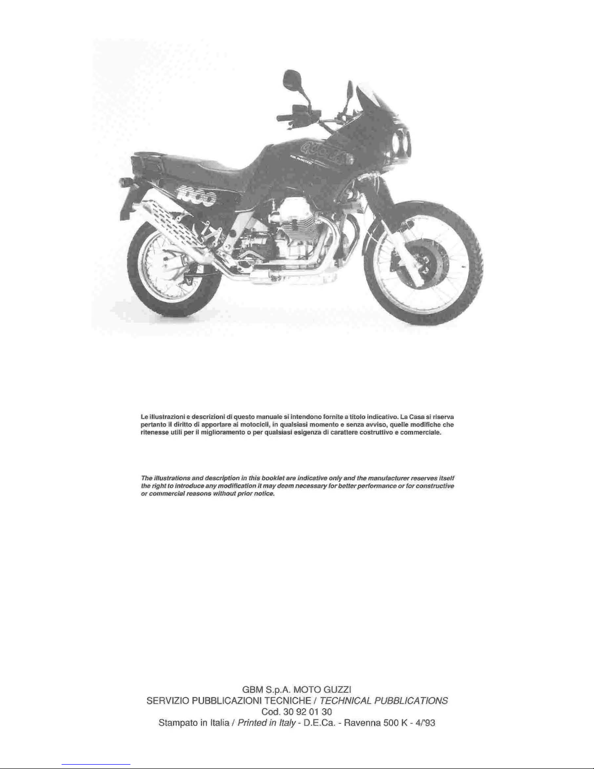
Le lIIuslrazioni e descrizlonl di questa manuale sl intendono fomite a tilolo Indicativa.
La
Casa sl rlserva
pertanto
II
diritto dl apportare ai motocicll. in qualsiasi momento e senza avviso. queUe modifiche che
rltenesse utili per
iI
miglloramento 0 per qualslasl eslgenza di caratlere costruttivo e commerciale.
The ilfustrations
and
description in this booklet
are
indicative only
and
the manufacturer reserves itself
the right to Introduce
any
modification It m
ay
deem necessary for better performance
or
for constructive
or
commercial reasons
wilham
prior notice.
GBM S.p.A.
MOTO
GUZZI
SERVIZIO PUBBLICAZIONI
TECNICHE / TECHNICAL PUBBLICATIONS
Cod. 30 92
01
30
Stampato in Italia / Printed in Italy - D.E.Ca. - Ravenna 500 K - 4r93

3

4
IN
DICE
CARATIERlsTICHE GENERAlI
pag.6
APPARECCHI
DI
CONTROllO
E
pag.9
pag.
11
REVlslONE E VERIFICA DEL MOTORE
pag.
13
12
.6
Valvo
Ie
e guidavalvole
12.12 Cilindri
12.13 Pistoni
12.16 Montaggio delle bielle sull
'albero motore
12.18
Controllo peso per I'equilibratura dell'albero
motore
lUBRIFICAZIONE DEL MOTORE
pag. 17
14.1
Pompa olio di mandata
INIEZIONE - ACCENslONE
pag.
18
TElAIO
pag
.24
sOsPENslONE POSTER
lORE
pag. 27
sOsPENslONE ANTERIORE
pag
.29
FORCEllONE
OsClllANTE
pag.31
INDEX
MAIN
FEATURES
page 6
INSTRUMENTS AND CONTROLS
page 9
page
12
ENGINE
OVERHAULING
AND
12.6 Valves and valve-guides
12.12 Cylinders
12_
13 Pistons
page
13
12.16 Fitting
of
the
connecting rods
on
the
crankshaft
12.18 Weight check for cra nkshaft balancing
ENGINE LUBRICA TlON
page 17
14_1
Oil delivery pump
INJECTION - IGNITION
page
18
FRAME
page 24
REAR
SiJSPENSION
page
27
FRONT
SUSPENSION
page
29
SWINGING
ARM
page
31

RUOTE
pag.32
23
.1
Ruota anteriore
23.3
Ru
ota posteriore
23.5
Pneumatici
23.10
Impianti idraulici
per freni
IMPIANTO ELETTRICO
pag.36
24.1
Batteria
24.2
Alternatore
- Regolatore
24.14
Im
pianto iliuminazione
SCHEMA IMPIANTO ELETTRICO
pag.40
25.1
Legenda schema impianto elettrico
WHEELS
page
32
23.1 Front wheel
23
.3
Rear wheel
23.5
Tyres
23.10 Brake hydraulic system
ELECTRICAL
EQUIPMENT
page
36
24.1
Battery
24.2
Alternator -Regulator
24.14 Lighting equipment
WIRING
DIAGRAM
page 40
25.1 Electric system scheme legend
5
6
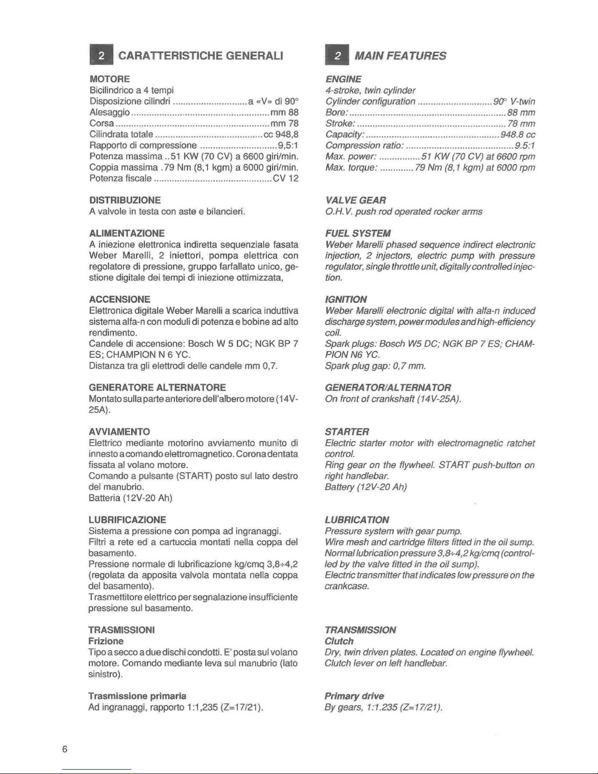
• CARATIERISTICHE GENERAL!
MOTORE
Bicilind
ri
co a 4 tempi
Disposizione cilindri ..............
.....
.........
. a "V» di 90°
Alesaggio
...................................................... mm 88
Corsa ...................
..
....................................... mm 78
Cilindrata totale .......................................... cc 948,8
Rapporto
di
compressione ........
....
........
....
...... 9,5:1
Potenza massima
..
51
KW (70 CV) a 6600 giri/min.
Coppia massima .79
Nm
(8,1
kgm) a 6000 giri/min.
Potenza fiscale ..............................................
CV
12
DlSTRIBUZIONE
A valvole
in
testa con aste e bilancieri.
AlIMENTAZIONE
A iniezione elettronica indiretta sequenziale fasata
Weber
Marelli, 2 iniettori, pompa elettrica con
regolatore
di
pressione, gruppo farfallato unico, ge-
stione
digitale dei tempi di iniezione ottimizzata,
ACCENSIONE
Elettronica digitale Weber Marelli a scarica induttiva
sistema
alfa-n con moduli di potenza e bobine ad alto
rendimento.
Candele di accensione: Bosch W 5 DC; NGK BP 7
ES; CHAMPION N 6 YC.
Distanza tra
gli elettrodi delle candele mm 0,
7.
GENERATORE
AL
TERNATORE
Montato sulla parte anteriore dell'albero motore (14V-
25A).
AVVIAMENTO
Elettrico
mediante motorinG avviamento munito
di
innesto a comando elettromagnetico. Corona dentata
fissata
al
volano motore.
Comando a
pulsante (START) posto
sullato
destro
del manubrio.
Batteria
(12V-2 0 Ah)
LUBRIFICAZIONE
Sistema a pressione con pompa ad ingranaggi.
Filtri a rete ed a cartuccia montati nella coppa del
basamento.
Pressione normale di lubrificazione kg/cmq 3,8+4
,2
(regolata da apposita valvola montata nella coppa
del basamento).
Trasmettitore
elettrico per segnalazione insufficiente
pressione s
ui
basamento.
TRASMISSIONI
Frizione
Tipo a secco a due dischi condotti. E' posta sui volano
motore. Comando mediante leva sui manu brio (Iato
sinistro).
Trasmi
ssione
primaria
Ad ingranaggi, rapporto 1:1,235 (Z=17/21).
• MAIN FEATURES
ENGINE
4-stroke, twin
cylinder
Cylinder
configuration .............................
9(1'
V-twin
Bore:
.............................................................
88
mm
Stroke: ......................................................
....
78 mm
Capacity: ..................................................
..
948.8 cc
Compression ratio: .......................................... 9.5:1
Max. power
: ................ 51
KW
(70 CV)
at
6600 rpm
Max. torque: .............
79
Nm
(8,
1
kgm)
at
6000 rpm
VALVE
GEAR
o.H
. V.
push
rod
operated
rocker
arms
FUEL
SYSTEM
Weber
Marelli
phased
sequence
indirect electronic
injection,
2 injectors, electric
pump
with
pressure
regulator
, single throttle unit, digitally controlled injec-
tion.
IGNITION
Weber Marelli electronic digital with a/fa-n
induced
discharge system,
power
modules
and
high-efficiency
coil.
Spark
plugs
: Bosch W5 DC;
NGK
BP 7 ES
; CHAM-
PION
N6
YC.
Spark
plug
gap
: 0
,7
mm.
GENERATOR/ALTERNATOR
On
front
of
crankshaft
(14 V-25A).
STARTER
Electric
starter
motor
with electromagnetic ratchet
control
.
Ring
gear
on the flywheel.
START
push-button
on
right handlebar.
Battery
(12V-20
Ah)
LUBRICA
TlON
Pressure
system
with
gear
pump
.
Wire
mesh
and
cartridge filters fitted in the
oil
sump.
Normallubrication
pressure
3,8+4
,2
kg/cmq
(control-
led
by
the valve fitted in the
oil
sump)
.
Electric transmitter that indicates
low
pressure on the
crankcase.
TRANSMISSION
Clutch
Dry
, twin driven
plates. Located
on engine flywheel.
Clutch
lever
on
left
handlebar
.
Primary
drive
By
gears
,
1:1.235
(Z=17/21).
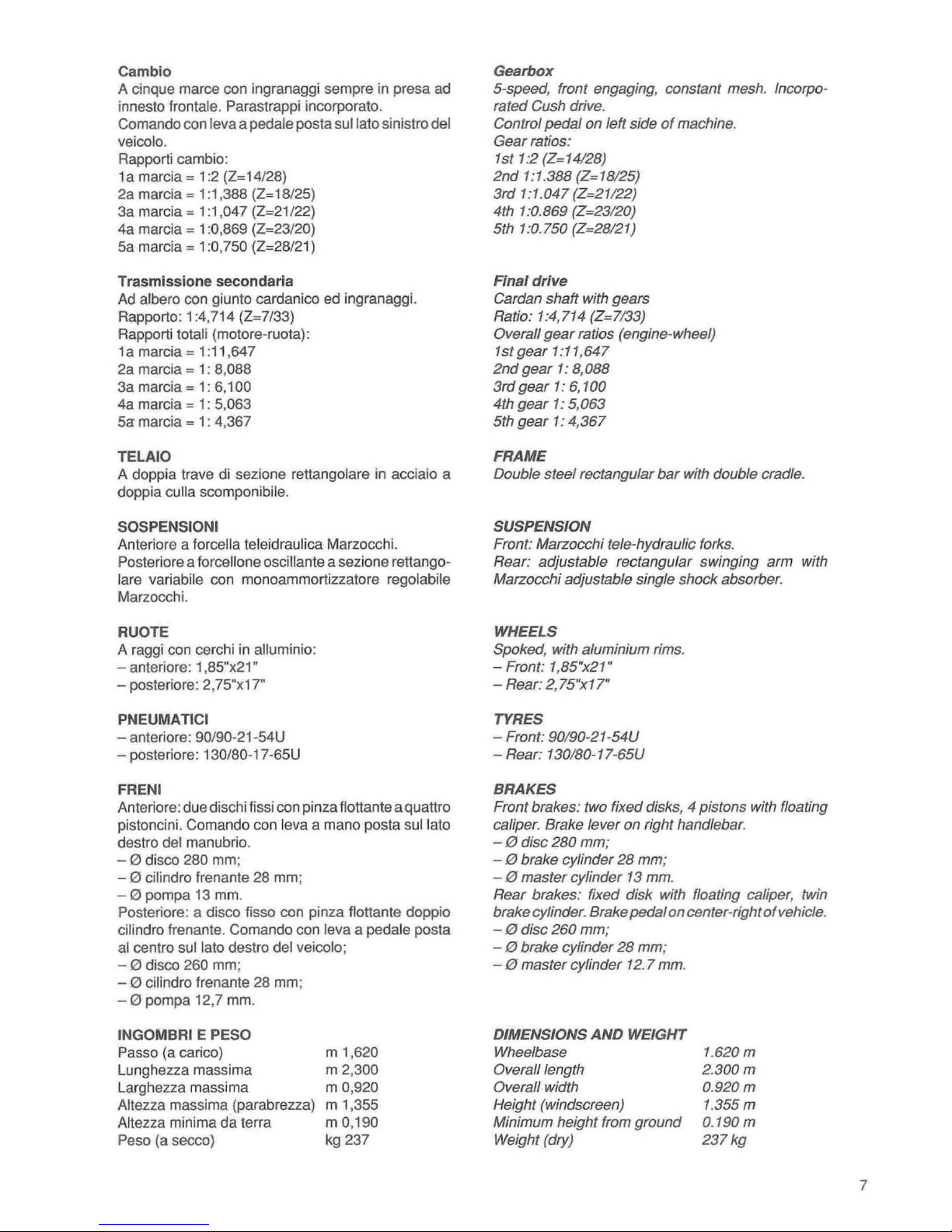
Cambia
A cinque marce can ingranaggi sempre in presa ad
innesto
lrontale. Parastrappi incorporato.
Comando con
leva a pedale posta sullato sinistro del
veicolo.
Rapporti cambio:
1 a marcia = 1
:2
(Z= 14/28)
2a marcia = 1 :1,388 (
Z=1B12S
)
3a marcia = 1 :1,047 (Z=21/22)
4a marcia = 1
:0,869 (Z=23/20)
Sa
marcia = 1 :0,750 (Z=28/21)
Trasmissione secondaria
Ad
albero con giunto cardanico ed ingranaggi.
Rapporto: 1
:4
,714 (Z=7/33)
Rapporti
totali (motore-ruota):
1a marcia = 1 :
11
,647
2a marcia = 1:
8,088
3a marcia = 1: 6,100
4a marcia = 1: 5,063
Sa
marcia = 1: 4,367
TELAIO
A doppia trave di sezione rettangolare in acciaio a
doppia culla scomponibile.
SOSPENSIONI
Anteriore a lorcella teleidraulica Marzocchi.
Posteriore a lorcellone oscillante a sezione rettangolare variabile con monoammortizzatore regolabile
Marzocchi.
RUOTE
A raggi con cerchi
in
alluminio:
-
anteriore: 1 ,
8S"
x21 "
- posteriore: 2,7S"x17"
PNEUMATICI
- anteriore: 90/90-21-S4U
-
posteriore: 130/80-17-6SU
FRENI
Anteriore: due dischi lissi con pinza Ilottante aquattro
pistoncini. Comando con
leva a mana posta
sullato
destro del manubrio.
- 0 disco 280 mm;
- 0 cilindro Irenante 28 mm;
- 0 pompa
13
mm.
Posteriore: a disco lisso con pinza Ilottante doppio
cilindro Irenante. Comando con leva a pedale posta
al
centro
sullato
destro del veicolo;
- 0 disco 260 mm;
- 0 cilindro frenante 28 mm;
- 0 pompa 12,7 mm.
INGOMBRI E PESO
Passo (a carico)
Lunghezza massima
Larghezza massima
Allezza massima (parabrezza)
Allezza minima da terra
Peso (a secco)
m
1,620
m 2,300
m 0,920
m 1,355
m
0,190
kg 237
Gearbox
5-speed, front engaging, constant mesh. Incorporated Cush drive.
Control pedal on left side
of
machine.
Gear ratios:
1st
1:2 (Z=14/28)
2nd
1:1.388 (Z=18/25)
3rd
1 :1.047 (Z=21/22)
4th
1 :0.869 (Z=23/2
0)
5th 1:0.750 (Z=28/21)
Final drive
Cardan shaft with gears
Ratio:
1 :4,714 (Z=7/33)
Overall
gear
ratios (engine-wheel)
1st
gear
1 :11,647
2nd
gear
1:
8,088
3rd
gear
1:
6,100
4th
gear
1:
5,063
5th gear
1:
4,367
FRAME
Double steel rectangular
bar
with double cradle.
SUSPENSION
Front: Marzocchi tele-hydraulic forks.
Rear: adjustable rectangular swinging arm with
Marzocchi adjustable single shock absorber.
WHEELS
Spoked, with aluminium rims.
- Front: 1,85"x21"
-
Rear: 2,
75"xl7"
TYRES
- Front: 90/90-21-54U
-
Rear: 130/80-17-65U
BRAKES
Front brakes: two fixed disks, 4 pistons with floating
caliper. Brake lever on right handlebar.
-
10
disc 280 mm;
-
10
brake cylinder
28
mm;
-
10
master cylinder 13 mm.
Rear brakes: fixed disk with floating caliper, twin
brake cylinder. Brake pedal on center-rightofvehicle.
-
10
disc 260 mm;
-
10
brake cylinder
28
mm;
-
10
master cylinder 12.7 mm.
DIMENSIONS AND WEIGHT
Wheelbase
Overall length
Overall width
Height (windscreen)
Minimum height from ground
Weight (dry)
1.620
m
2.300m
0.
920m
1.355m
0.190 m
237
kg
7
8
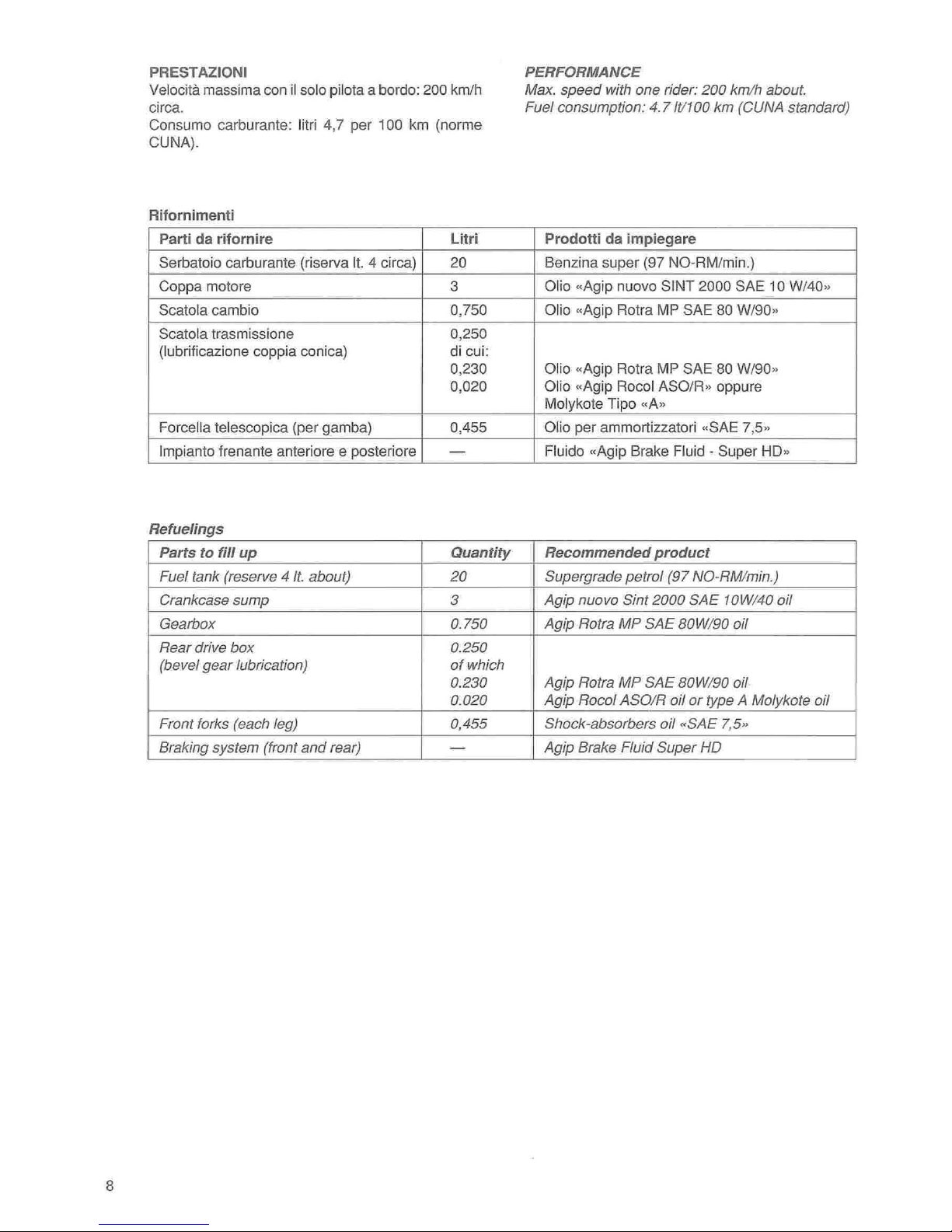
PRESTAZIONI
Velocitil
massima con
il
solo pilota a bordo: 200 kmlh
circa.
Consumo carburante:
litri 4,7 per 100
km
(norme
CUNA).
Rifornimenti
Parti da
rifornire
Litri
Serbatoio carburante (riserva
It.
4 circa)
20
Coppa motore 3
Scatola cambio 0,750
Scatola
trasmissione 0,250
(I
ubrificazione coppia coni
cal
di cui:
0,230
0,020
Foreelia teleseopiea
(per gamba) 0,455
Impianto
frenante anteriore e posteriore -
Refuelings
Parts
to
fill
up
Quantity
Fuel
tank
(reserve 4 It. about)
20
Crankcase
sump
3
Gearbox
0.750
Rear
drive
box
0.250
(bevel
gear
lubrication)
of
which
0.230
0.
020
Front forks (each leg) 0,
455
Braking
system
(front a
nd
rear) -
PERFORMANCE
Max.
speed
with
one
rider:
200
km
/h
about
Fuel
consumption:
4.7111100
km
(CUNA standard)
Prodotti
da
impiegare
Benzina super (97 NO-RM/min
.)
Olio «Ag
ip
nuovo SINT 2000 SAE 10 W/40"
Olio «Agip Rotra MP SAE 80 W/90"
Ol
io
«Agip Rotra
MP
SAE
80
W/90"
Ol
io
«Agip
Roeo
l ASO
/R"
oppure
Molykote Tipo «A"
Olio
per ammortizzatori «SAE
7,5"
Fl
uido «Agip Brake Fluid - Super HD"
Recommended
product
Supergrade
petrol
(97
NO-RM/min.)
Agip
nuovo
Sint
2000
SAE
10W/40
oil
Agip
Rotra
MP
SAE
BOW/90
oil
Agip
Rotra
MP
SAE
BOW/90
oil
Agip
Rocol
ASO/R
oil
or
type A Molykote
oil
Shock-absorbers
oil
.SAE
7,5"
Agip
Brake
Fluid
Super
HD

•
APPARECCHI
01
CONTROllO
E
COMANOI
Quadro
di
controllo
(Iig. 1)
1 Commutatore a chiave per inserimento
utilizzatori
e bloccasterzo.
Posizione
«OFF» veicolo lermo. Chiave estraibile
(nessun contatto);
Posizione
«ON» veicolo pronto per I'awiamento.
Tutti gli utilizzatori so
no
inseriti. Chiave non estraibile;
Posizione
«LOCK» sterzo bloccato a sinistra.
Motore spento, ness
un
contatto, chiave estraibile.
Posizione
«P»
ster
zo
bloccato. Motore spento; con
I'interruttore
«A»
di
lig . 2 in posizione "p
..
si ha la luce
di
parcheggio. Chiave estraibile.
Per azionare
iI
dispositivo bloccasterzo operare come
segue:
• Ruotare
il
manubrio verso sinistra .
• Premere la chiave verso
il
basso e ruotarla in
senso antiorario sino
alia posizione «LOCK
..
0 "p
".
A TTENZIONE:
non
girare
la
chiave
in
posizione
"LOCK» 0 "P»
durante
la marcia.
2 Tachimetro contachilometri.
3 Azzeratore per contachilometri parziale.
4 Contagiri.
5
Spia (Iuce verde) «Neutr
al
..
indicatore cambio in
lolle.
Si
accende con
il
cambio
in
folie.
6 Spia (Iuce verde) per lampeggiatori.
7
Spia (Iuce bleu) luce abbagliante.
8
Spia (Iuce rossa) pressione olio.
Si
spegne quan-
do la pressione
Ii sufficiente ad assicurare la
lubrificazione del motore.
Se la spia non si spe-
gne, la pressione non
Ii quella prescritta; in tal
caso, occorre fermare immediatamente
il
motore
ed effettuare
Ie
opportune ricerche.
9
Spia (Iuce rossa) erogazione corrente del generatore.
Si
deve spegnere appena
iI
motore ha rag-
giunto un certo numero di giri.
10 Spia (Iuce arancio) riserva carburante.
11
Commutatore per inserimento lampeggiatori
di
emergenza.
12
Spia predisposta per controllo in officina dell'im-
pianto iniezione elettronica, (check-lamp).
INSTRUMENTS
AND
CONTROLS
Control
panel
(fig.
1)
1 Key switch for devices
and
steering lock.
Position
"OFF"
vehicle stationary. Key removable
(no contact).
Position
"ON»
vehicle ready
to
be statted.
All
circuits are
on.
Key
not
removable.
Position
«LOCK"
steering locked
to
the left.
Engine off, no contact, key removable.
Position
"P"
steering locked. Engine off; with switch
«A» offig. 2
in
position
«P»
the parking light is
on.
Key
removable.
In
order to use the steering lock mechanism, proceed
as follows:
• Turn the handlebars
to
the left.
• Press the key down
and
turn anti-clockwise to
position
«LOCK»
or "P».
WARNING:
Never
turn
the
key
to
position
"LOCK"
or
"P»
when
the
engine
is
running.
2 Odometer, tachometer.
3 Partial odometer zeroing
4 Rev counter.
5 Pilot light (green)
«Neutral» for neutral position.
Lights up when the gearbox is
in
neutral.
6 Pilot light (green) for flashing indicators.
7 Pilot light (blue) for main beam.
8
Oil pressure pilot light (red). Goes
out
when the oil
pressure is sufficient to ensure engine lubrication.
If the pilot light doesn't go out, then the pressure
is not
at
the required level;
in
this case, stop the
engine immediately and check the fault.
9 Pilotlight(red} forgeneratorcurrentoutpuf. Should
go
out
when the engine reaches a certain number
of
revs.
10 Petrol tank reserve pilot light (orange).
11
Switch for hazard warning lights.
12 Pilot light fitted for workshop test on electronic
injection system, (check-lamp).
9
10
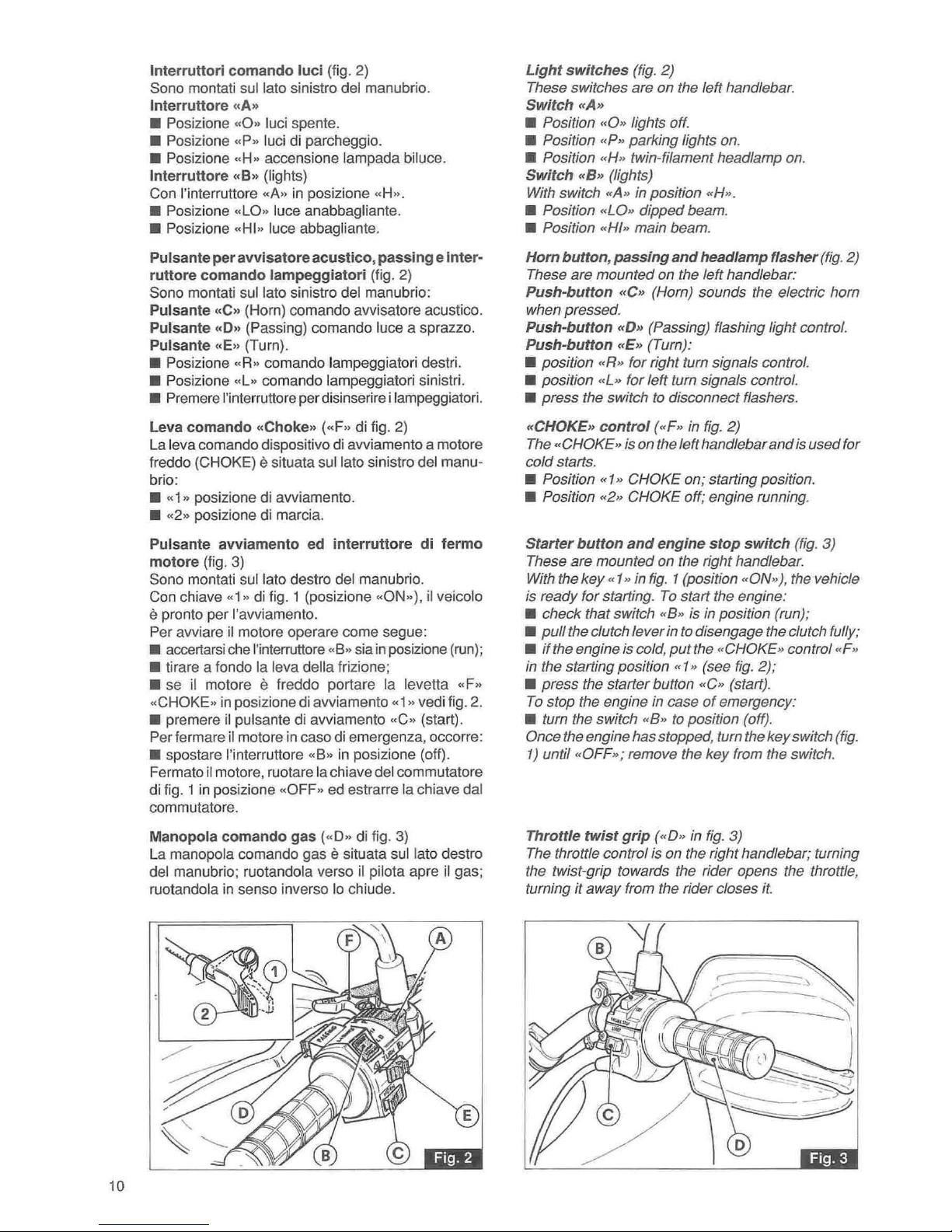
Interruttori
comando
luci
(fig. 2)
Sono montati sui lato sinistro del manubrio.
Interruttore
«A.
• Posizione
..
0
..
luci spente.
• Posizione
..
p
..
luei di parcheggio.
• Posiz ione
.. H ..
accensione lampada biluee.
Interruttore
«B.
(lights)
Con I'interruttore «A»
in
posizione uH
».
• Posizione
..
LO
..
luee anabbagliante.
• Posizione
..
HI
..
luce abbagliante.
Pulsante
per
avvisatore
acustico, passing e inter-
ruttore comando
lampeggiatori
(fig. 2)
Sono montati
sullato
sinistro del manubria:
Pulsante
«C.
(Horn) comando
awisatore
acustico.
Pulsante
«D.
(Passing) comando luce a sprazzo.
Pulsante
«E
..
(Turn).
• Posizione
..
R
..
comando lampeggiatori destri.
• Posizione
..
L» eomando lampeggiatori sinistri.
• Premere I'interruttore per disinserire i lampeggiatori.
Leva
comando
..
Choke. ( ..
F» di fig. 2)
La leva eomando dispositivo di avviamento a motore
freddo
(CHOKE) e situata
sullato
sinistro del manu-
bria:
•
.. 1 ••
posizione di avviamento.
• «2» posizione
di
marcia.
Pulsante
avviamento
ed
interruttore
di
fermo
motore
(fig. 3)
Sana montati sui lata
des
tro del manubria.
Can chiave
.. 1 ..
di fig. 1 (posizione
.. ON»),
il
veicolo
e pronto per I'avviamento.
Per
awiare
il
motore operare come segue:
• accertarsi ehe I'interruttore
..
8» sia in posizione (run);
• tirare a fondo la leva della frizione;
• se
il
motor
e e freddo portare la levetta
.. F ..
..
CHOKE
..
in posizione di
awiamen
to
.. 1 ..
vedi fig.
2.
• premere il pulsante di avviamento
.. C ..
(start).
Per fermare
il
motore in easo di emergenza. occorre:
• spostare I'interruttore
..
8»
in
posizione (off).
Fermato
iI
motore, ruotare l
achiave
del commutatore
di fig. 1 in posizione
..
OFF
..
ed estrarre la chiave dal
commutatore.
Manopola
comando
gas ( .. 0 ..
di fig. 3)
La
manopola comando
gas
e situata sui lato destro
del manubrio; ruotandola verso
il
pilota apre
iI
gas
;
ruotandola in senso inverso
10
chiude.
Light
switches (fig. 2)
These switches are on the left handlebar.
Switch
..
A»
• Position
«0
» lights off.
• Position «P" parking fights on.
• Position «H» twin-fifament headlamp on.
Switch
,,
8» (fights)
With switch
«A»
in
position «H
».
• Position «LO» dipped beam.
• Position «HI» main beam.
Horn
button, passing
and
headlamp flasher (fig. 2)
These are mounted on the left handlebar:
Push-button
"C.
(Hom) sounds the electric hom
when pressed.
Push-button
..
0 » (Passing) flashing light control.
Push-button
"E»
(Tum):
• position «R» for right tum signals control.
• position
..
L» for left tum signals control.
• press the switch
to
disconnect flashers.
"CHOKE»
control
(<<F»
in
fig.
2)
The
«CHOKE» is on the left handlebar and is used for
cold starts.
• Position
«1"
CHOKE on; starting position.
• Position «2» CHOKE off; engine running.
Starter
button
and
engine
stop
switch
(fig. 3)
These are mounted on the right handlebar.
With the key
«1
..
in
fig. 1 (position «ON,,), the vehicle
is ready for starting.
To
start the engine:
• check that switch «8 » is
in
position (run);
• pull the clutch lever in
to
disengage the clutch fully;
•
if
the engine is cold, put the
..
CHOKE» control «F»
in
the starting position «1» (see fig. 2);
• press the starter button
«C»
(start).
To
stop the engine
in
case
of
emergency:
• tum the switch «8»
to
position (off).
Once the engine has stopped, tum the key switch (
fig
.
1) until
«
OFF
»; remove the key from the switch.
Throttle twist
grip (<<
0"
in
fig.
3)
The throttle control
is
on the right handlebar; turning
the twist-grip towards the rider opens the throttl
e,
turning it away from the rider closes
it.
~
~
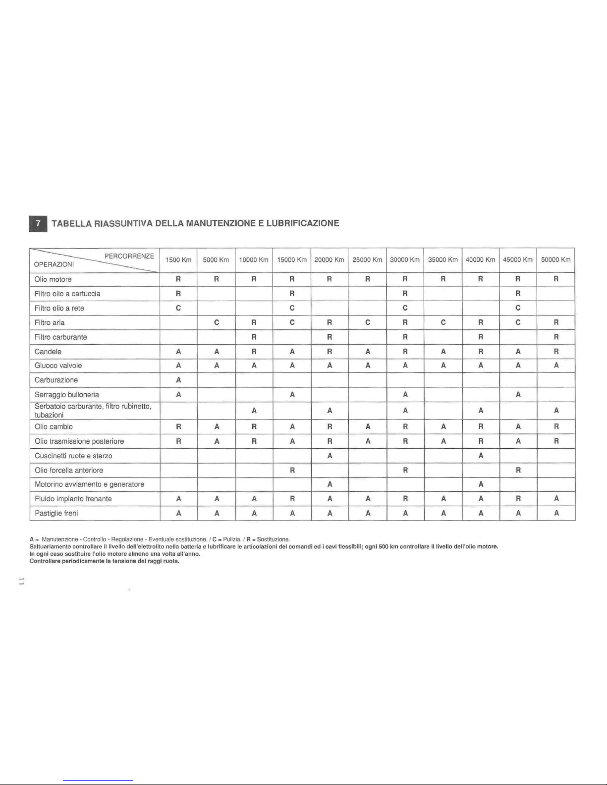
• TABELLA RIASSUNTIVA DELLA MANUTENZIONE E LUBRIFICAZIONE
PERCORRENZE
1500 Km 5000 Km 10000 Km
15000 Km
20000
Km
25000
Km
30000
Km
35000 Km 40000 Km
OPERAZIONI
Olio motore
R R R R R R
R R
R
Filtro olio a cartuccia R R
R
Filtro olio a rete C C C
Filtro aria C R
C
R C R C R
Filtro carburante R R R R
Candele A A R A R A R A R
Giuoco valvole A
A
A
A
A A A A A
Carburazione
A
Serraggio bulloneria
A A
A
Serbatoio carburante, liltro rubinetto,
A A A A
tubazioni
Olio cambio R A R A R A R A R
Olio trasmissione posteriore R A R A R A R A R
Cuscinetti ruote e sterzo A A
Olio lorce/la anteriore
R
R
Motorino avviamento e generatore A A
Fluido impianto
Irenante
A A A R A A
R
A
A
Pastiglie Ireni A A
A A A
A
A A A
A
:=
Manutenzione'
Cantralla . Regolazione
- E
ventuate
sostituzione.
1 C
==
Pul
izia.
I A
'"
Sostituz
ione.
Saltuarlamente controllare IIl1velio
dell'elettrollto
nella
batteria e lubrificare
Ie
Brticolazloni
del
comandi
ed
i cavl11esslblllj
ognl
500
km
controllare IIII\lelio
deU'olio
motore.
In
ognl
caso
sostltuJre
"olio motore almena
una
volta
all'anno.
Controilare periodlcamente
la
tensione del
raggl
ruota.
45000
Km
50000
Km
R R
R
C
C
R
R
A
R
A A
A
A
A
R
A
R
R
R
A
A A

~
'"
II
MAINTENANCE
AND
LUBRICATION OPERATIONS
--
--
MILEAGE COVERED 1000 mi. 3000 mi.
6000 mi. 9000 mi. 120
00
mi. 15000 mi. 18000 mi.
ITEMS
(1
500 Km)
(5000 Km) (10000 Km) (15000 Km) (20000 Km) (25000 Km) (30000 Km)
Engine oil
R R R R
R R R
Oil filter cartridge
R R
R
Wire gauze oil filter
C C
C
Air
filter
C R C R
C
R
Fuel filter
R R R
Spark plugs
A A R A R A
R
Rocker clearance
A A A A A A A
Carburation
A
Nuts and bolts .
A
A A
Fuel tank, tap filter
and
pipes
A A
A
Gearbox oil
R A
R A R A R
Re
ar
drive box oil
R
A R A R A R
Wheel
and
steering bearings
A
Front forks oil
R R
Starter motor and generator
A
Brake system fluid A
A A R A A R
Brake pads A A A
A
A
A A
-- -- -
--
--
A = Maintenance·
Inspe
ction·
Adjustment·
Possible
replacemen
t.!
C =
Cleaning
) R =
Replacement
.
Occasionally check the electrolyte lev
el
in
the battery and lubricate control joints and cables;
every
500
km (300
miles) check the engine
aI/level
.
The all
should be changed at least once a
yesr, In
any
case.
Periodically check the tautness
of
the wheel spokes.
21000 m
i.
24000 m
i.
27000
mi.
30000 mi.
(35000 Km) (40000 Km)
(45000
Km)
(50000 Km)
R R R
R
R
C
C
R C R
R
R
A
R A R
A
A A
A
A
A A
A R A R
A R
A R
A
R
A
A
A R
A
A A A A

II
REVISIONE E VERI FICA DEL MO-
TORE
ENGINE OVERHAULING
AND
CHECKING
13
 Loading...