

MOTO GUZZI NORGE GT 8V Service Station Manual
SERVICE STATION MANUAL
897237
Norge GT 8v

SERVICE STATION
Revente Interdite - Revendita Vietata - Resaling Forbiden - Wiederverkauf Verboten
MANUAL
Norge GT 8v
While the basic features as described and illustrated in this manual remain unchanged, Moto Guzzi
s.p.a. reserves the right to introduce changes to their own models at any time. All rights regarding
electronic data storage, total or partial reproduction or adaptation of this manual by any means are
reserved for all Countries. Third party products or services referred to in this manual should be considered
only informative and are not binding. Moto Guzzi s.p.a. shall not be liable for any functions or use of these
products.

SERVICE STATION MANUAL
Revente Interdite - Revendita Vietata - Resaling Forbiden - Wiederverkauf Verboten
Norge GT 8v
This manual provides the main information to carry out regular maintenance operations on your scooter.
This manual is intended to Moto Guzzi Dealers and their qualified mechanics; several concepts have
been deliberately omitted as they are considered unnecessary. As it is not possible to include complete
mechanical notions in this manual, users should have basic mechanical knowledge or minimum
knowledge about the procedures involved when repairing scooters. Without this knowledge, repairing or
checking the vehicle may be inefficient or even dangerous. As the vehicle repair and check procedures
are not described in detail, be extremely cautious so as not to damage components or injure individuals.
In order to optimise customer satisfaction when using our vehicles, Moto Guzzi s.p.a. commits itself to
continually improve its products and the relative documentation. The main technical modifications and
changes in repair procedures are communicated to all Moto Guzzi Sales Outlets and its International
Subsidiaries. These changes will be introduced in the subsequent editions of the manual. In case of
need or further queries on repair and check procedures, consult Moto Guzzi CUSTOMER
DEPARTMENT, which will be prepared to provide any information on the subject and any further
communications on updates and technical changes related to the vehicle.
2011
NOTE Provides key information to make the procedure easier to understand and carry out.
CAUTION Refers to specific procedures to carry out for preventing damages to the vehicle.
WARNING Refers to specific procedures to carry out to prevent injuries to the repairer.
Personal safety Failure to completely observe these instructions will result in serious risk of personal
injury.
Safeguarding the environment Sections marked with this symbol indicate the correct use of the vehicle
to prevent damaging the environment.
Vehicle intactness The incomplete or non-observance of these regulations leads to the risk of serious
damage to the vehicle and sometimes even the invalidity of the guarantee.
Revente Interdite - Revendita Vietata - Resaling Forbiden - Wiederverkauf Verboten
INDEX OF TOPICS
Revente Interdite - Revendita Vietata - Resaling Forbiden - Wiederverkauf Verboten
CHARACTERISTICS CHAR
SPECIAL TOOLS S-TOOLS
MAINTENANCE MAIN
ELECTRICAL SYSTEM ELE SYS
ENGINE FROM VEHICLE ENG VE
ENGINE ENG
POWER SUPPLY P SUPP
SUSPENSIONS SUSP
CHASSIS CHAS
BRAKING SYSTEM BRAK SYS
BODYWORK BODYW
PRE-DELIVERY PRE DE

INDEX OF TOPICS
Revente Interdite - Revendita Vietata - Resaling Forbiden - Wiederverkauf Verboten
CHARACTERISTICS CHAR
Norge GT 8v Characteristics
Revente Interdite - Revendita Vietata - Resaling Forbiden - Wiederverkauf Verboten
Rules
Safety rules
Carbon monoxide
If you need to keep the engine running while working on the vehicle, please ensure that you do so in
an open or very well ventilated area. Never let the engine run in an enclosed area. If you do work in an
enclosed area, make sure to use a fume extraction system.
CAUTION
EXHAUST EMISSIONS CONTAIN CARBON MONOXIDE, A POISONOUS GAS WHICH CAN CAUSE
LOSS OF CONSCIOUSNESS AND EVEN DEATH.
Fuel
CAUTION
FUEL USED TO POWER INTERNAL COMBUSTION ENGINES IS HIGHLY FLAMMABLE AND CAN
BECOME EXPLOSIVE UNDER SPECIFIC CONDITIONS. IT IS THEREFORE RECOMMENDED TO
CARRY OUT REFUELLING AND MAINTENANCE PROCEDURES IN A VENTILATED AREA WITH
THE ENGINE SWITCHED OFF. DO NOT SMOKE DURING REFUELLING AND NEAR FUEL VAPOURS, AVOID ANY CONTACT WITH NAKED FLAMES, SPARKS OR OTHER SOURCES WHICH
MAY CAUSE THEM TO IGNITE OR EXPLODE.
DO NOT DISPERSE FUEL IN THE ENVIRONMENT.
KEEP OUT OF THE REACH OF CHILDREN.
Hot components
The engine and the exhaust system components become very hot and remain hot for some time after
the engine has been switched off. Before handling these components, make sure that you are wearing
insulating gloves or wait until the engine and the exhaust system have cooled down.
Used engine oil and transmission oil
CAUTION
IT IS ADVISABLE TO WEAR LATEX GLOVES WHEN SERVICING THE VEHICLE.
THE ENGINE OR GEARBOX OIL MAY CAUSE SERIOUS INJURIES TO THE SKIN IF HANDLED
FOR PROLONGED PERIODS OF TIME AND ON A REGULAR BASIS.
WASH YOUR HANDS CAREFULLY AFTER HANDLING OIL.
HAND THE OIL OVER TO OR HAVE IT COLLECTED BY THE NEAREST USED OIL RECYCLING
COMPANY OR THE SUPPLIER.
DO NOT DISPOSE OF OIL IN THE ENVIRONMENT
KEEP OUT OF THE REACH OF CHILDREN.
Brake and clutch fluid
CHAR - 7
Characteristics Norge GT 8v
Revente Interdite - Revendita Vietata - Resaling Forbiden - Wiederverkauf Verboten
BRAKE AND CLUTCH FLUIDS CAN DAMAGE THE PLASTIC OR RUBBER PAINTED SURFACES.
WHEN SERVICING THE BRAKING OR THE CLUTCH SYSTEM PROTECT THESE COMPONENTS
WITH A CLEAN CLOTH. ALWAYS WEAR PROTECTIVE GOGGLES WHEN SERVICING THESE
SYSTEMS. BRAKE AND CLUTCH FLUIDS ARE EXTREMELY HARMFUL FOR YOUR EYES. IN
THE EVENT OF ACCIDENTAL CONTACT WITH THE EYES, RINSE THEM IMMEDIATELY WITH
PLENTY OF COLD, CLEAN WATER AND SEEK MEDICAL ADVICE.
KEEP OUT OF THE REACH OF CHILDREN.
Battery electrolyte and hydrogen gas
CAUTION
THE BATTERY ELECTROLYTE IS TOXIC, CORROSIVE AND, AS IT CONTAINS SULPHURIC
ACID, MAY CAUSE BURNING IF IT COMES INTO CONTACT WITH THE SKIN. WHEN HANDLING
BATTERY ELECTROLYTE, WEAR TIGHT-FITTING GLOVES AND PROTECTIVE APPAREL. IN
THE EVENT OF SKIN CONTACT WITH THE ELECTROLYTIC FLUID, RINSE WELL WITH PLENTY
OF CLEAN WATER. IT IS PARTICULARLY IMPORTANT TO PROTECT YOUR EYES BECAUSE
EVEN TINY AMOUNTS OF BATTERY ACID MAY CAUSE BLINDNESS. IN THE EVENT OF CONTACT WITH THE EYES, RINSE WITH PLENTY OF WATER FOR FIFTEEN MINUTES AND CONSULT AN EYE SPECIALIST IMMEDIATELY. IF THE FLUID IS ACCIDENTALLY SWALLOWED,
DRINK LARGE QUANTITIES OF WATER OR MILK, FOLLOWED BY MILK OF MAGNESIA OR
VEGETABLE OIL AND SEEK MEDICAL ADVICE IMMEDIATELY. THE BATTERY RELEASES EXPLOSIVE GASES; KEEP IT AWAY FROM FLAMES, SPARKS, CIGARETTES OR ANY OTHER
HEAT SOURCES. ENSURE ADEQUATE VENTILATION WHEN SERVICING OR RECHARGING
THE BATTERY.
KEEP OUT OF THE REACH OF CHILDREN.
BATTERY LIQUID IS CORROSIVE. DO NOT POUR IT OR SPILL IT, PARTICULARLY ON PLASTIC
COMPONENTS. ENSURE THAT THE ELECTROLYTIC ACID IS COMPATIBLE WITH THE BATTERY BEING ACTIVATED.
Maintenance rules
GENERAL PRECAUTIONS AND INFORMATION
When repairing, disassembling and reassembling the vehicle, strictly follow the recommendations reported below.
BEFORE DISASSEMBLING COMPONENTS
•
Before dismantling components, remove dirt, mud, dust and foreign bodies from the vehicle.
Use the special tools designed for this bike, as required.
COMPONENTS REMOVAL
•
Do not loosen and/or tighten screws and nuts using pliers or any other tools than the specific
wrench.
•
Mark the positions on all connection joints (pipes, cables, etc.) before separating them, and
identify them with different distinctive symbols.
•
Each component needs to be clearly marked to enable identification during reassembly.
•
Clean and wash the dismantled components carefully using a low-flammability detergent.
CHAR - 8

Norge GT 8v Characteristics
Revente Interdite - Revendita Vietata - Resaling Forbiden - Wiederverkauf Verboten
•
Keep mated parts together since they have "adjusted" to each other due to normal wear.
•
Some components must be used together or replaced altogether.
•
Keep away from heat sources.
REASSEMBLING COMPONENTS
CAUTION
BEARINGS MUST ROTATE FREELY, WITHOUT JAMMING AND/OR NOISE, OTHERWISE, THEY
NEED TO BE REPLACED.
•
Only use ORIGINAL Moto Guzzi SPARE PARTS.
•
Comply with lubricant and consumables use guidelines.
•
Lubricate parts (whenever possible) before reassembling them.
•
When tightening nuts and screws, start from the ones with the largest section or from the
internal ones, moving diagonally. Tighten nuts and screws in successive steps before applying the tightening torque.
•
Always replace self-locking nuts, washers, sealing rings, circlips, O-rings (OR), split pins
and screws with new ones if their tread is damaged.
•
When assembling the bearings, make sure to lubricate them well.
•
Check that each component is assembled correctly.
•
After a repair or routine maintenance procedure, carry out pre-ride checks and test the vehicle on private grounds or in an area with low traffic density.
•
Clean all coupling surfaces, oil guard rims and gaskets before refitting them. Smear a light
layer of lithium-based grease on the oil guard rims. Reassemble oil guards and bearings
with the brand or lot number facing outward (visible side).
ELECTRIC CONNECTORS
Electric connectors must be disconnected as described below; failure to comply with this procedure
causes irreparable damage to both the connector and the wiring harness:
Press the relative safety clips, if applicable.
•
Grip the two connectors and disconnect them by pulling them in opposite directions.
•
If any signs of dirt, rust, moisture, etc. are noted, clean the inside of the connector carefully
with a jet of compressed air.
•
Ensure that the cables are correctly fastened to the internal connector terminals.
•
Then connect the two connectors, ensuring that they couple correctly (if fitted with clips, you
will hear them "click" into place).
CAUTION
DO NOT DISCONNECT CONNECTORS BY PULLING THE CABLES.
NOTE
THE TWO CONNECTORS CAN ONLY BE CONNECTED IN ONE DIRECTION: CONNECT THEM
THE RIGHT WAY ROUND.
TIGHTENING TORQUES
CAUTION
REMEMBER THAT THE TIGHTENING TORQUES FOR ALL FASTENING ELEMENTS ON WHEELS,
BRAKES, WHEEL AXLES AND ANY OTHER SUSPENSION COMPONENTS PLAY A KEY ROLE
CHAR - 9
Characteristics Norge GT 8v
Revente Interdite - Revendita Vietata - Resaling Forbiden - Wiederverkauf Verboten
IN ENSURING VEHICLE SAFETY AND MUST COMPLY WITH SPECIFIED VALUES. CHECK THE
TIGHTENING TORQUES OF FASTENING ELEMENTS ON A REGULAR BASIS AND ALWAYS USE
A TORQUE WRENCH TO REASSEMBLE THESE COMPONENTS. FAILURE TO COMPLY WITH
THESE RECOMMENDATIONS MAY CAUSE ONE OF THESE COMPONENTS TO LOOSEN OR
EVEN DETACH, CAUSING A WHEEL TO LOCK OR COMPROMISING VEHICLE HANDLING. THIS
MAY LEAD TO FALLS, WITH THE RISK OF SERIOUS INJURY OR DEATH.
Running-in
Engine run-in is essential to ensure engine long life and correct operation. Twisty roads and gradients
are ideal to run in engine, brakes and suspensions effectively. Vary your riding speed during the runin. This ensures that components operate under both "loaded" and "unloaded" conditions, allowing the
engine components to cool.
CAUTION
THE CLUTCH MAY EMIT A SLIGHT BURNING SMELL WHEN FIRST USED. THIS PHENOMENON
SHOULD BE CONSIDERED NORMAL AND WILL DISAPPEAR AS SOON AS THE CLUTCH DISCS
GET ADAPTED.
IT IS IMPORTANT TO STRAIN ENGINE COMPONENTS DURING RUN-IN, HOWEVER, MAKE SURE
NOT TO OVERDO THIS.
CAUTION
THE FULL PERFORMANCE OF THE VEHICLE IS ONLY AVAILABLE AFTER THE SERVICE AT
THE END OF THE RUN-IN PERIOD.
Follow the guidelines detailed below:
•
Do not twist the throttle grip abruptly and completely when the engine is working at a low
revs, either during or after run-in.
•
During the first 100 Km (62 miles) use the brakes gently, avoiding sudden or prolonged
braking. That is to permit the adequate adjustment of the pad friction material to the brake
discs.
AFTER THE SPECIFIED MILEAGE, TAKE THE VEHICLE TO AN OFFICIAL Moto Guzzi DEALER
FOR THE CHECKS INDICATED IN THE "AFTER RUN-IN" TABLE IN THE SCHEDULED MAINTENANCE SECTION TO AVOID INJURING YOURSELF, OTHERS AND /OR DAMAGING THE VEHICLE.
Vehicle identification
SERIAL NUMBER LOCATION
These numbers are necessary for vehicle registration.
NOTE
ALTERING IDENTIFICATION NUMBERS MAY BE SERI-
OUSLY PUNISHABLE BY LAW. IN PARTICULAR, MODIFYING THE CHASSIS NUMBER IMMEDIATELY VOIDS THE
WARRANTY.
CHAR - 10

Norge GT 8v Characteristics
Revente Interdite - Revendita Vietata - Resaling Forbiden - Wiederverkauf Verboten
ENGINE NUMBER
The engine number is stamped on the left side,
close to the engine oil level check cap.
This number consists of numbers and letters, as in the example shown below.
ZGULPS010YMXXXXXX
KEY:
ZGU: WMI (World manufacturer identifier) code;
LP: model;
S01: version variation;
0: free digit
Y year of manufacture
M: production plant (M= Mandello del Lario);
XXXXXX: serial number (6 digits);
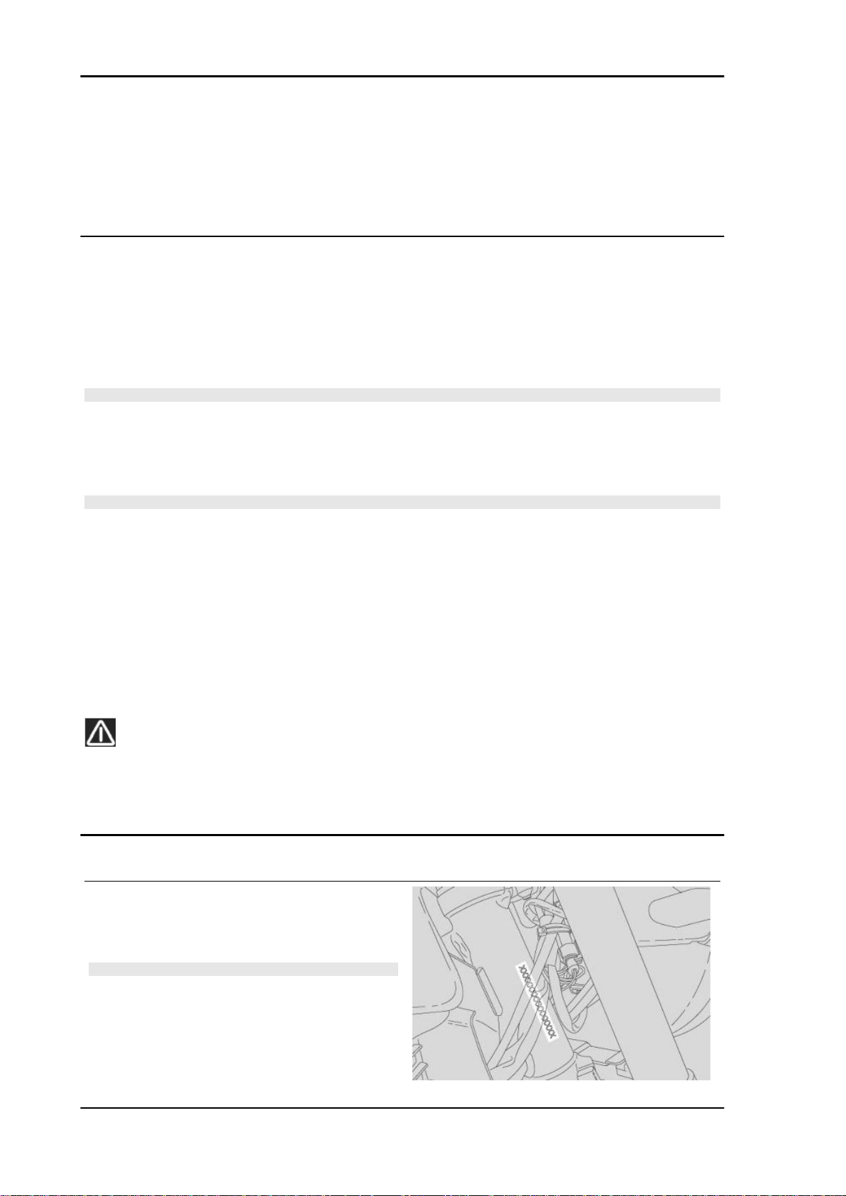
CHASSIS NUMBER
The chassis number is stamped on the right hand side of the headstock.
Dimensions and mass
WEIGHT AND DIMENSIONS
Specification
Max. length 2195 mm (86.4 in)
Max. width 880 mm (34.6 in)
Max. height (to the windshield) 1430 - 1480 mm (56.3 - 58.3 in)
Saddle height 810 mm (31.9 in)
Minimum ground clearance 185 mm (72.8 in)
Wheelbase 1495 mm (58.8 in)
Kerb weight 257 Kg (566.6 lb)
Desc./Quantity
Engine
ENGINE
Specification
Type traverse-mounted twin-cylinder four-stroke V 90°
No. of cylinders 2
Cylinder arrangement V of 90°
Bore / stroke 95 x 81.2 mm (3.74 x 3.20 in)
Engine capacity 1151 cm³ (70 cu.in.)
Compression ratio 10.8 : 1
Electric starter
Engine idle speed 1100 ± 100 rpm
Desc./Quantity
CHAR - 11

Characteristics Norge GT 8v
Revente Interdite - Revendita Vietata - Resaling Forbiden - Wiederverkauf Verboten
Specification Desc./Quantity
Clutch hydraulically controlled single-plate dry clutch with incorpora-
Lubrication system Pressure-fed, controlled by valves and trochoidal pump
Air filter cartridge-type dry filter
Cooling air and oil cooled with independent trochoidal pump and oil
pressure control valve
Timing system single overhead camshaft with bucket tappets and rocker-op-
Valve Four valves for each cylinder
Values valid with control clearance between rockers and valve intake: 0.15 mm (0.0059 in)
ted flexible coupling
erated valves
exhaust: 0.20 mm (0.0079 in)
Transmission
TRANSMISSION
Specification Desc./Quantity
Primary drive with gears, ratio: 24/35 = 1:1.4583
Gearbox Mechanical, 6 speeds with foot lever on the left hand side of
Gear ratios, 1st gear 17/38 = 1:2.2353
Gear ratios, 2nd gear 20/34 = 1:1.7
Gear ratios, 3rd gear 23/31 = 1:1.3478
Gear ratios, 4th gear 26/29 = 1:1.1154
Gear ratios, 5th gear 31/29 = 1:0.9355
Gear ratios, 6th gear 30/24 = 1:0.8
Final drive with U-joint
Ratio 12/44 = 1:3.6667
the engine
Capacities
Specification
Engine oil Oil and oil filter change: 3400 cm³ (207.48 cu.in)
Gearbox oil 500 cm³ (30.5 cu.in)
Transmission oil 380 cm³ (23.2 cu.in)
Fuel (reserve included) 23 litres (5.06 UK gal)
Fuel reserve 4 litres (0.88 UK gal)
Maximum weight limit 349 Kg (769.4 lb)
Olio forcella anteriore 400 +/- 2.5 cc (24.4 +/- 0.15 cu in) (per ogni stelo)
Electrical system
Specification
Spark plug NGK PMR8B (long life)
Alternative spark plug NGK CR8EKB
Electrode gap 0.6 - 0.7 mm (0.024 - 0.028 in)
Alternator (permanent magnet type) 12 V - 550 W
Main fuses 20A - 30A - 40A
Secondary fuses 3 - 10 - 15 A
Front daylight running light 12V - 5W
Rear daylight running light/stop light LED
High beam light 12 V - 65 W H1
Low beam light 12 V - 55 W H3
Turn indicator light 12 V - 10 W (orange)
License plate light 12V - 5 W
CAPACITIES
Desc./Quantity
Seats 2
ELECTRICAL SYSTEM
Desc./Quantity
Battery 12 V - 18 Ampere/hour
CHAR - 12
Norge GT 8v Characteristics
Revente Interdite - Revendita Vietata - Resaling Forbiden - Wiederverkauf Verboten
Specification Desc./Quantity
Dashboard lighting LED
Turn indicator warning light LED
Neutral gear warning light LED
Side stand down warning light LED
Low fuel warning light LED
High beam warning light LED
ABS warning light LED
Gear shift warning light LED
Antitheft device warning light LED
Alarm warning light LED
Frame and suspensions
CHASSIS
Specification Desc./Quantity
Type High strength tubular steel frame
Trail 120 mm (4.72 in)
Headstock angle 25° 30'
Steering angle 32°
Front 45 mm (1.77 in) telescopic hydraulic fork with adjustable spring
Front wheel travel 120 mm (4.7 in)
Rear single sided swingarm with progressive linkage and mono-
shock absorber with adjustable rebound and with ergonomic
hand grip for preloading adjustment.
Rear wheel travel 140 mm (5.5 in)
preload.
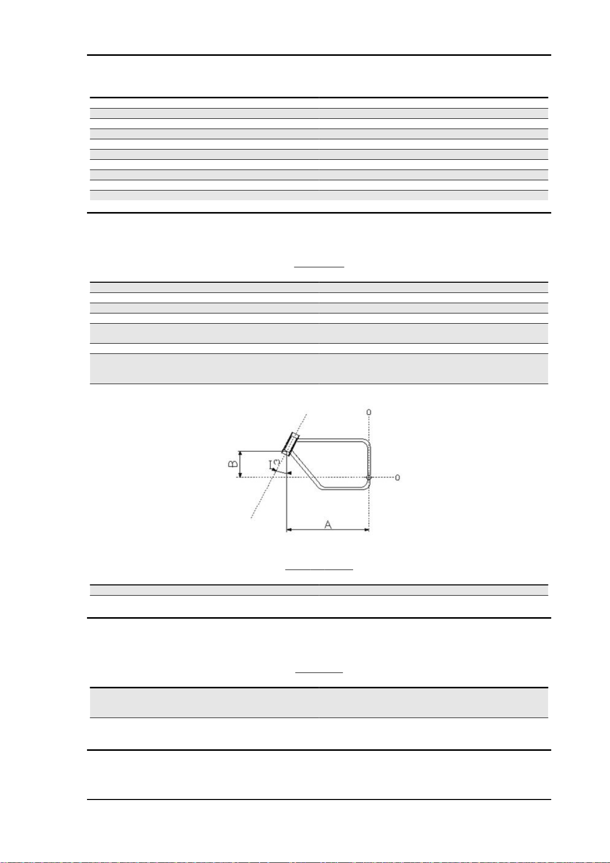
SIZES A AND B
Specification
Size A 758.9 +/- 1 mm (29.88 +/- 0.04 in)
Size B 345.5 mm (13.60 in)
Desc./Quantity
Brakes
BRAKES
Specification
Front Dual 320 mm (12.6 in) diam. stainless steel floating wavy disc
with radial callipers with 4 differentiated, horizontally opposed
Rear 282 mm (11.1 in) diam. stainless steel disc, calliper with two
Desc./Quantity
pistons.
parallel pistons
CHAR - 13
Characteristics Norge GT 8v
Revente Interdite - Revendita Vietata - Resaling Forbiden - Wiederverkauf Verboten
Wheels and tyres
WHEELS AND TYRES
Specification Desc./Quantity
Wheel rims - type hollow 3-spoke rim in chilled cast aluminium alloy
Wheel rims - front 3.5 '' x 17''
Wheel rims - rear 5.5 '' x 17''
Tyre type DUNLOP Roadsmart - Pirelli Angel
Front tyre size 120/70 - ZR 17''
Front tyre pressure 2.5 bar (250 kPa) (36.26 PSI)
Front tyre pressure with passenger 2.5 bar (250 kPa) (36.26 PSI)
Rear tyre size 180 / 55 - ZR 17''
Rear tyre pressure 2.8 bar (280 kPa) (40.61 PSI)
Rear tyre pressure with passenger 2.8 bar (280 kPa) (40.61 PSI)
Supply
FUEL SYSTEM
Specification Desc./Quantity
Fuel system Electronic injection (Weber . Marelli) with stepper motor
Diffuser diameter: 50 mm (1.97 in)
Fuel Premium unleaded petrol, minimum octane rating 95 (NORM)
and 85 (NOMM)
Tightening Torques
Front side
CHAR - 14
Norge GT 8v Characteristics
Revente Interdite - Revendita Vietata - Resaling Forbiden - Wiederverkauf Verboten
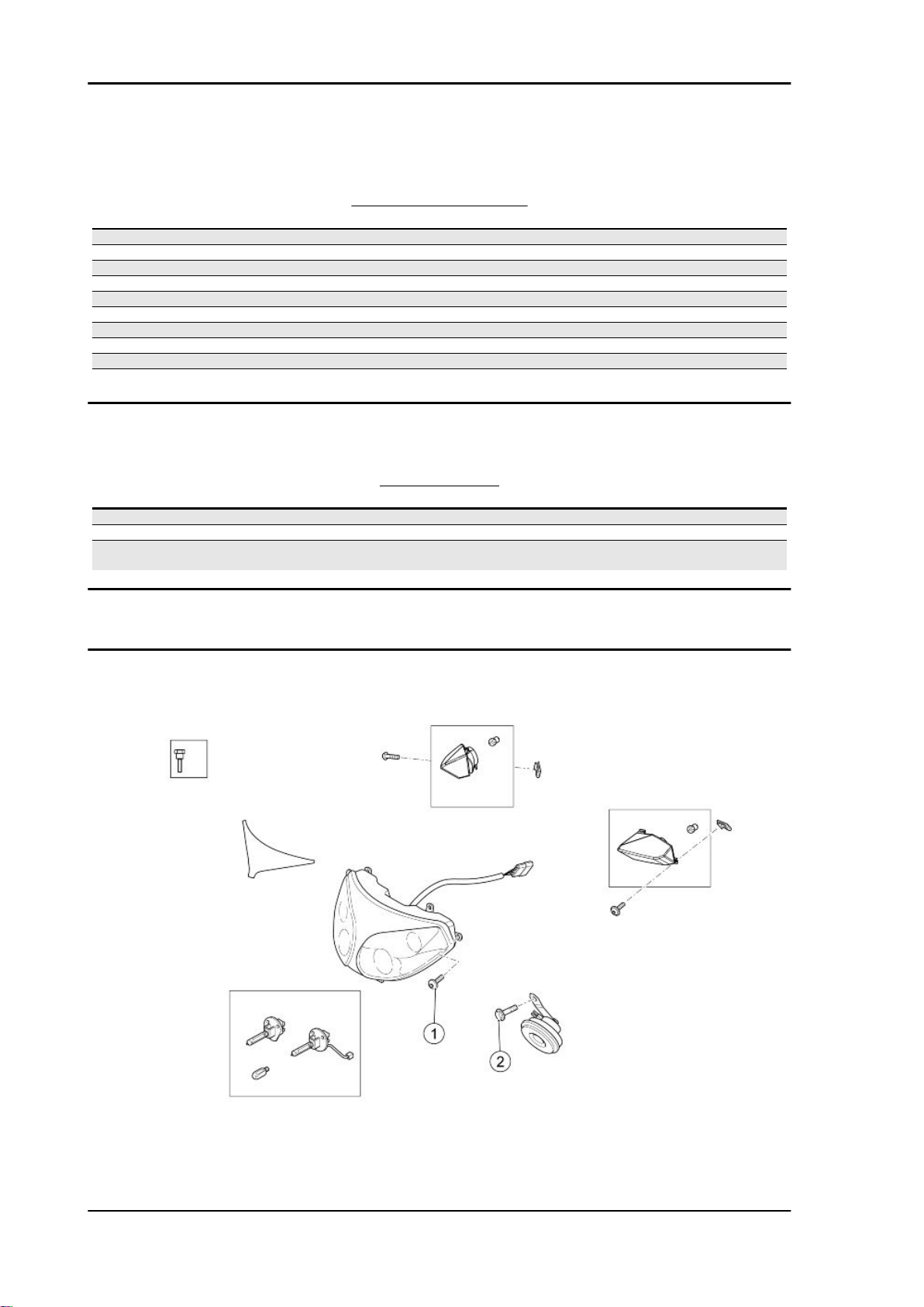
FRONT LIGHTS
pos. Description Type Quantity Torque Notes
1 Headlamp fixing screw M5 4 6 Nm (4.42 lbf ft) 2 Horn fixing screw M6 1 10 Nm (7.37 lbf ft) -
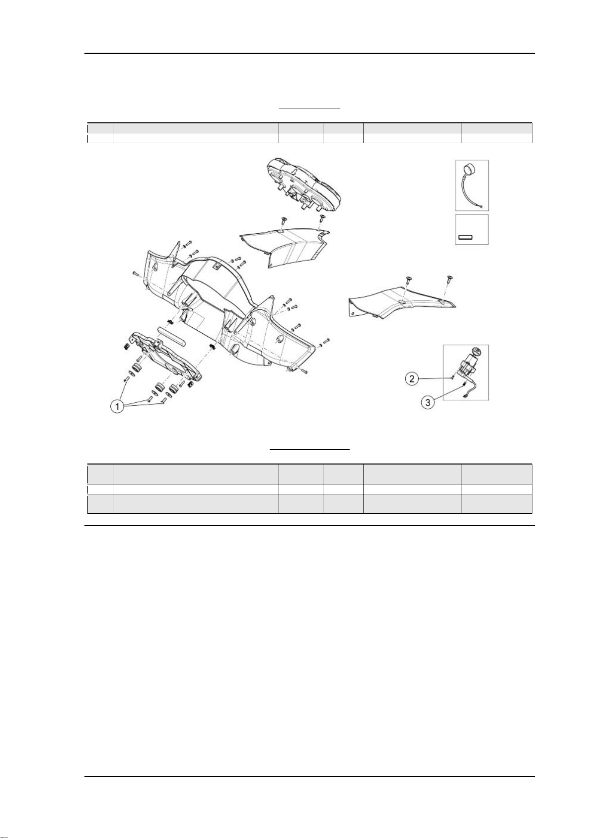
INSTRUMENT PANEL
pos.
1 Instrument panel fixing screw SWP
2 Ignition lock fixing screw M8x30 1 25 Nm (18.44 lbf ft) -
3 Ignition lock shear head fixing screw M8x28 1 - At the point of fail-
Description Type Quantity Torque Notes
3 3 Nm (2.21 lbf ft) -
M5x14
ure
CHAR - 15

Characteristics Norge GT 8v
Revente Interdite - Revendita Vietata - Resaling Forbiden - Wiederverkauf Verboten
FRONT FORK
pos.
1 Wheel axle locking screw on the fork leg M6 4 10 Nm (7.37 lbf ft) 2 Piston fixing screw to the sleeve M10x35 2 50 Nm (36.87 lbf ft) 3 Fork cap - 2 20 Nm (14.75 lbf ft) -
Description Type Quantity Torque Notes
WINDSHIELD
pos.
1 Top fairing fixing screw M5x9 8 4 Nm (2.95 lbf ft) -
CHAR - 16
Description Type Quantity Torque Notes
Norge GT 8v Characteristics
Revente Interdite - Revendita Vietata - Resaling Forbiden - Wiederverkauf Verboten
pos. Description Type Quantity Torque Notes
2 Top fairing fixing screw M5x16 2 4 Nm (2.95 lbf ft) -
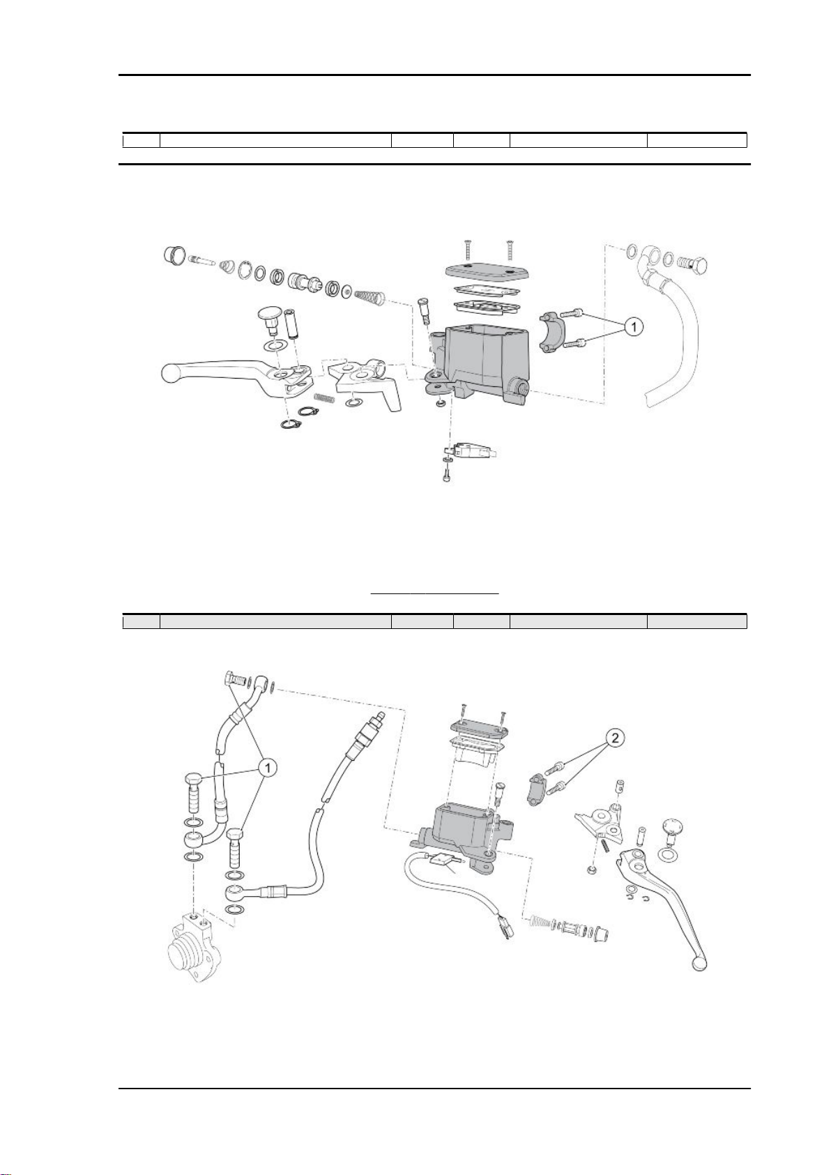
FRONT BRAKE LEVER
pos.
1 Front brake pump U-bolt fixing screw M6 2 10 Nm (7.37 lbf ft) Sequence 1-2-1
Description Type Quantity Torque Notes
CHAR - 17
Characteristics Norge GT 8v
Revente Interdite - Revendita Vietata - Resaling Forbiden - Wiederverkauf Verboten
CLUTCH CONTROL
pos. Description Type Quantity Torque Notes
1 Clutch pipe fixing slot screw M10 3 10 Nm (7.37 lbf ft) 2 Clutch pump U-bolt fixing screw M6 2 10 Nm (7.37 lbf ft) Sequence 1-2-1
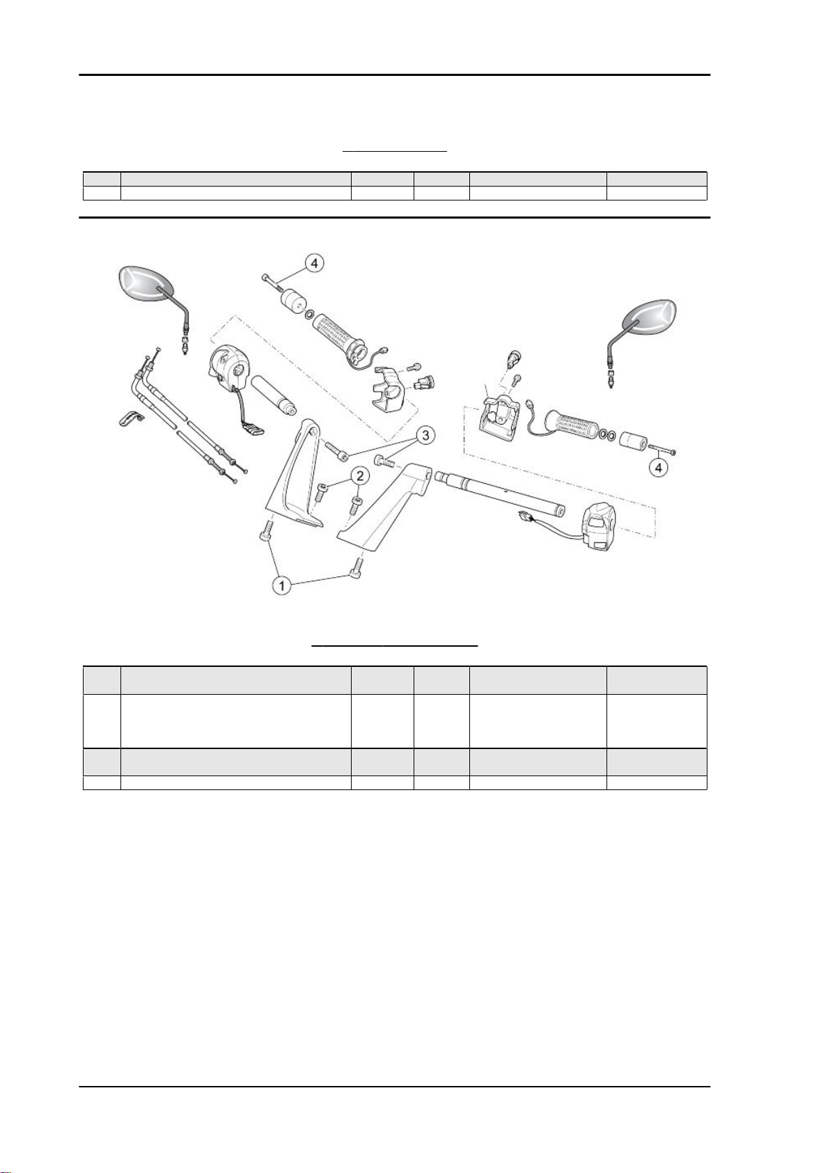
HANDLEBAR AND CONTROLS
pos.
2 Half-handlebar lower fixing screw on the up2 Half-handlebar upper fixing screw on the up-
3 Handlebar pipe fixing screw on the half-han4 Counterweight fixing screw M6x70 2 10 Nm (7.37 lbf ft) Loctite 243
Description Type Quantity Torque Notes
per steering yoke
per steering yoke
dlebar
M8x25 2 25 Nm (18.44 lbf ft) M8x25
STAIN-
LESS
STEEL
M8x30 2 18 Nm (13.27 lbf ft) Loctite 243
4 20 Nm (14.75 lbf ft) Loctite 243
CHAR - 18
Norge GT 8v Characteristics
Revente Interdite - Revendita Vietata - Resaling Forbiden - Wiederverkauf Verboten
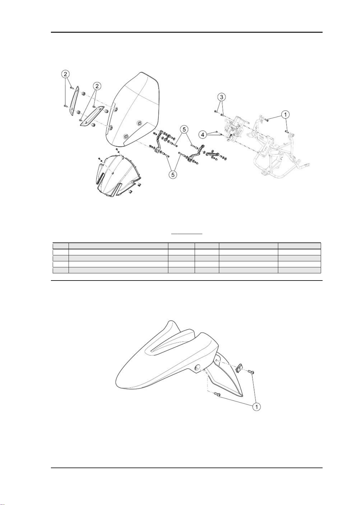
WINDSHIELD
pos.
1 Windshield link rod fixing screw on the frame M6x25 2 10 Nm (7.37 lbf ft) 2 Aesthetic support fixing screw M5 4 4 Nm (2.95 lbf ft) 3 Engine guide lock to frame upper fixing screw M6 2 10 Nm (7.37 lbf ft) 4 Engine guide lock to frame lower fixing screw M6 2 10 Nm (7.37 lbf ft) 5 Windshield support fixing screw M6 4 10 Nm (7.37 lbf ft) -
Description Type Quantity Torque Notes
CHAR - 19
Characteristics Norge GT 8v
Revente Interdite - Revendita Vietata - Resaling Forbiden - Wiederverkauf Verboten
FRONT MUDGUARD
pos. Description Type Quantity Torque Notes
1 Front mudguard fixing screw M5x12 4 4 Nm (2.95 lbf ft) -
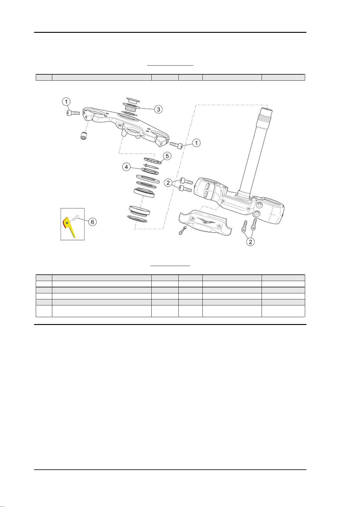
STEERING YOKE
pos.
1 Fork stanchion fixing screw on the upper plate M8x30 2 25 Nm (18.44 lbf ft) 2 Fork stanchion fixing screw on the lower plate M8x25 4 25 Nm (18.44 lbf ft) 3 Upper yoke fixing cap M29 1 100 Nm (73.76 lbf ft) 4 Headstock ring nut M35 1 40 Nm (29.50 lbf ft) 5 Headstock counter-lock ring M35 1 - Manually screw
6 Pipe stop plate fixing screw to the steering
Description Type Quantity Torque Notes
M6x18 1 10 Nm (7.37 lbf ft) -
base
CHAR - 20
Norge GT 8v Characteristics
Revente Interdite - Revendita Vietata - Resaling Forbiden - Wiederverkauf Verboten
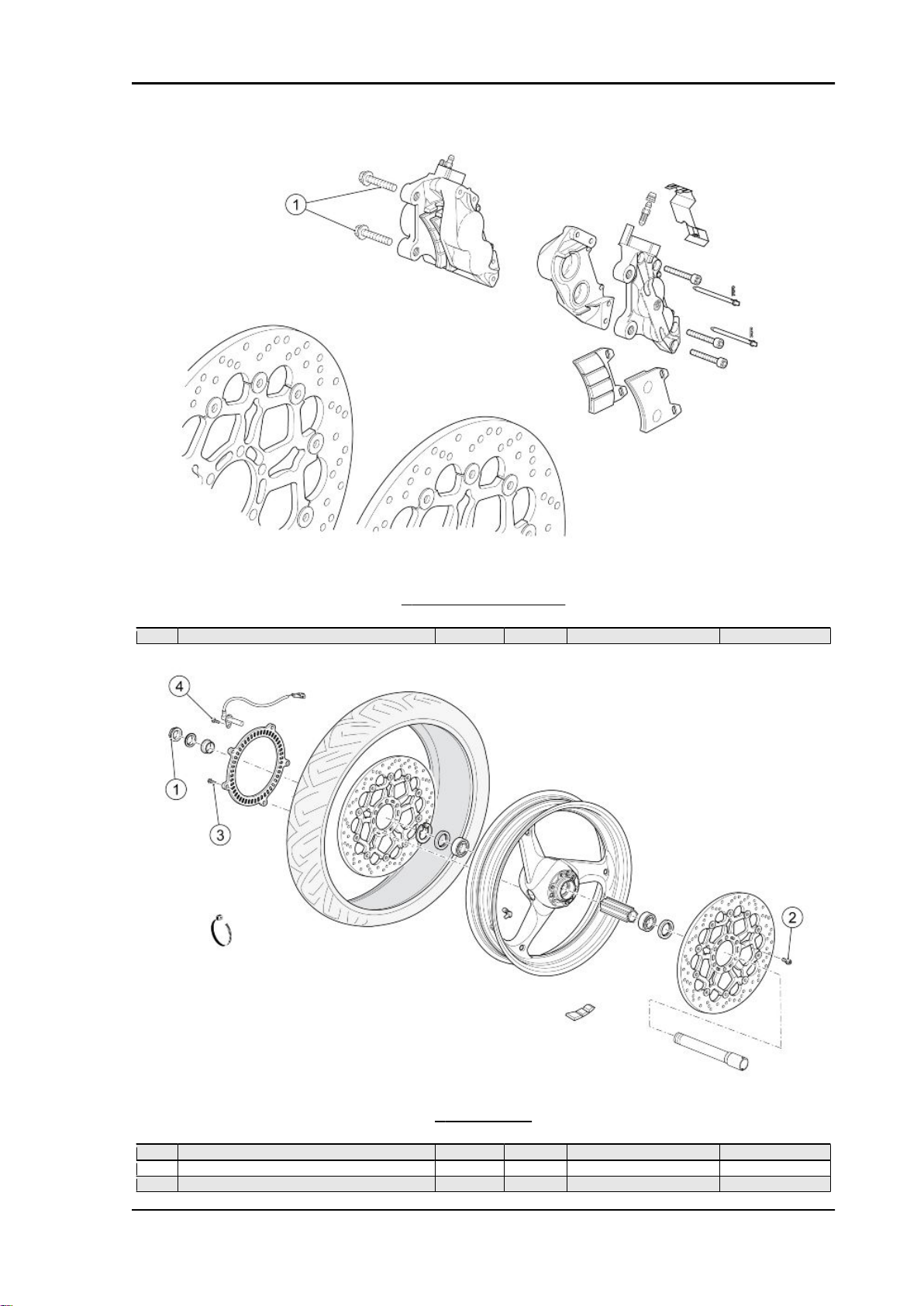
FRONT BRAKE CALLIPERS
pos.
1 Front brake calliper fixing screws M10 4 50 Nm (36.87 lbf ft) -
Description Type Quantity Torque Notes
FRONT WHEEL
pos.
1 Front wheel spindle nut M25 1 80 Nm (59.00 lbf ft) 2 Front brake disc fixing screw M8x20 12 25 Nm (18.44 lbf ft) Loctite 243
3 Front tone wheel fixing screw - 5 4 Nm (2.95 lbf ft) Loctite 243
Description Type Quantity Torque Notes
CHAR - 21
Characteristics Norge GT 8v
Revente Interdite - Revendita Vietata - Resaling Forbiden - Wiederverkauf Verboten
pos. Description Type Quantity Torque Notes
4 Front ABS sensor fixing screw M6 1 10 Nm (7.37 lbf ft) -
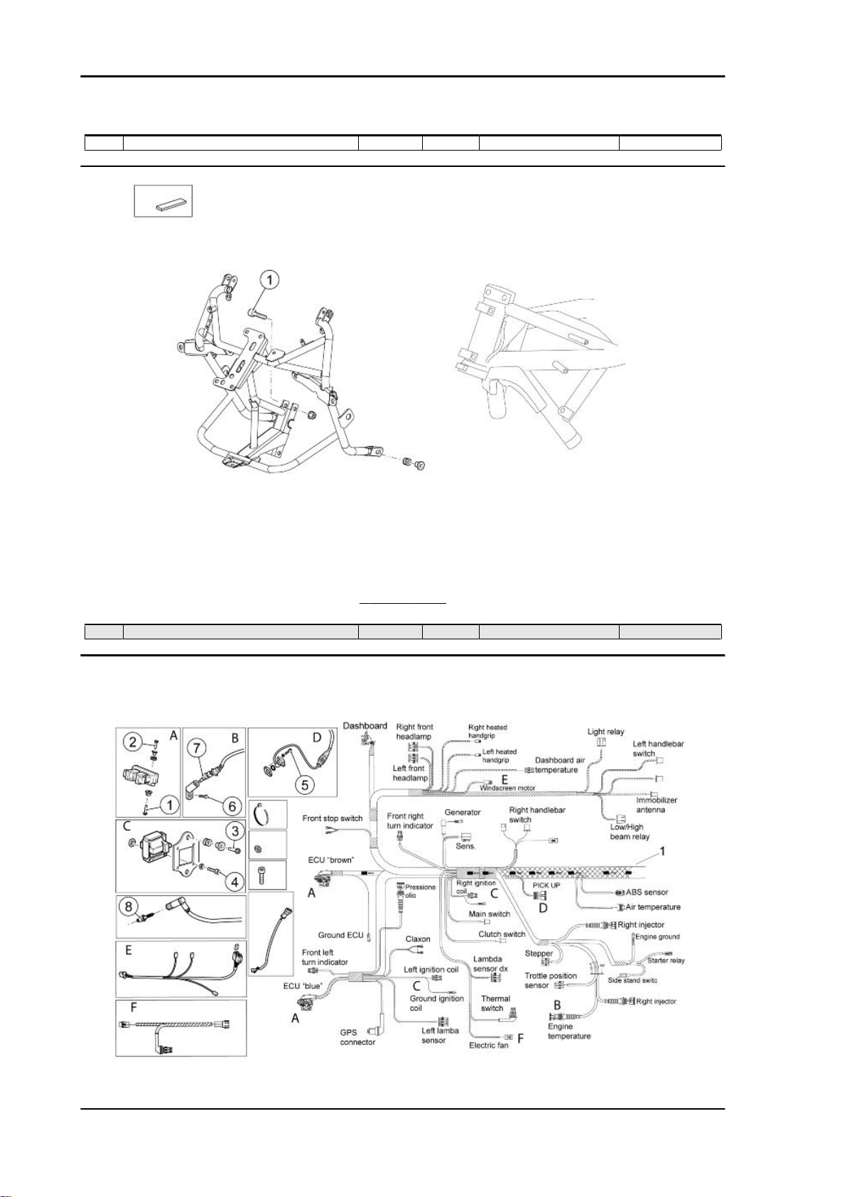
FRONT FRAME
pos.
1 Frame to chassis fixing screw M8x40 2 10 Nm (7.37 lbf ft) -
Description Type Quantity Torque Notes
Central part
CHAR - 22
Norge GT 8v Characteristics
Revente Interdite - Revendita Vietata - Resaling Forbiden - Wiederverkauf Verboten
MAIN CABLE HARNESS
pos. Description Type Quantity Torque Notes
1 Electronic control unit lower fixing screw M6x20 4 10 Nm (7.37 lbf ft) 2 Electronic control unit upper fixing screw M6x35 4 10 Nm (7.37 lbf ft) 3 Coil support plate fixing screw M6x20 4 10 Nm (7.37 lbf ft) 4 Coil fixing screw to the support plate M4x25 8 2 Nm (1.47 lbf ft) 5 Timing sensor fixing screw M5x12 2 6 Nm (4.42 lbf ft) 6 Oil temperature sensor support fixing screw M10x20 1 11 Nm (8.11 lbf ft) Loctite 243
7 Oil temperature sensor - 1 12 Nm (8.85 lbf ft) Kluber Wolfacoat
8 Spark plug - 2 15 Nm (11.06 lbf ft) -
Grease
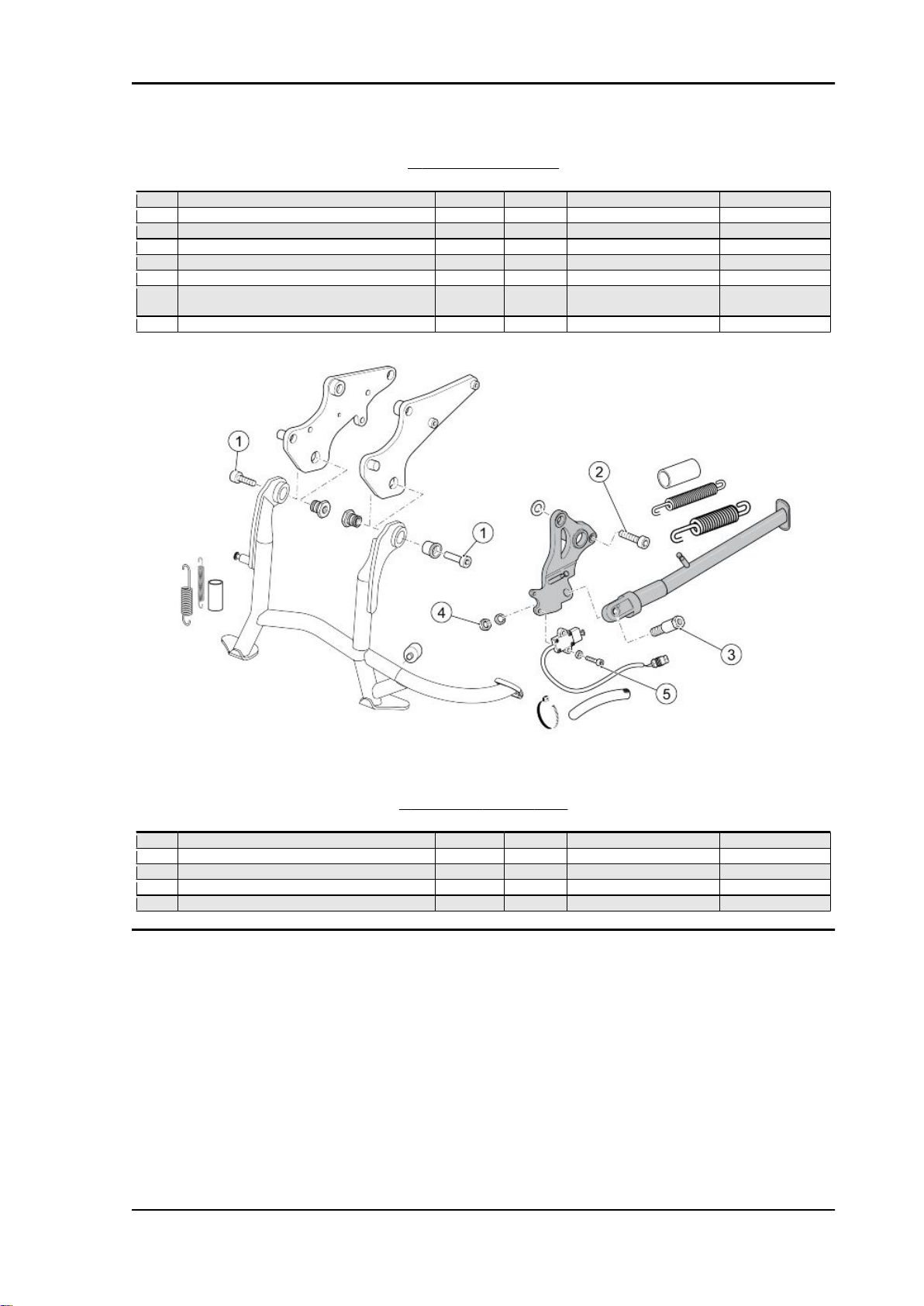
CENTRE AND SIDE STAND
pos.
1 Centre stand on the plate fixing screw M10x30 2 10 Nm (7.37 lbf ft) Loctite 243
2 Side stand plate to chassis fixing screw M12x35 2 80 Nm (59 lbf ft) 3 Side stand retainer pin M10 1 10 Nm (7.37 lbf ft) Loctite 270
4 Stand pin lower nut M10x1.25 1 30 Nm (22.13 lbf ft) Loctite 270
5 Side stand switch fixing screw M5x16 2 6 Nm (4.42 lbf ft) Loctite 243
Description Type Quantity Torque Notes
CHAR - 23
Characteristics Norge GT 8v
Revente Interdite - Revendita Vietata - Resaling Forbiden - Wiederverkauf Verboten
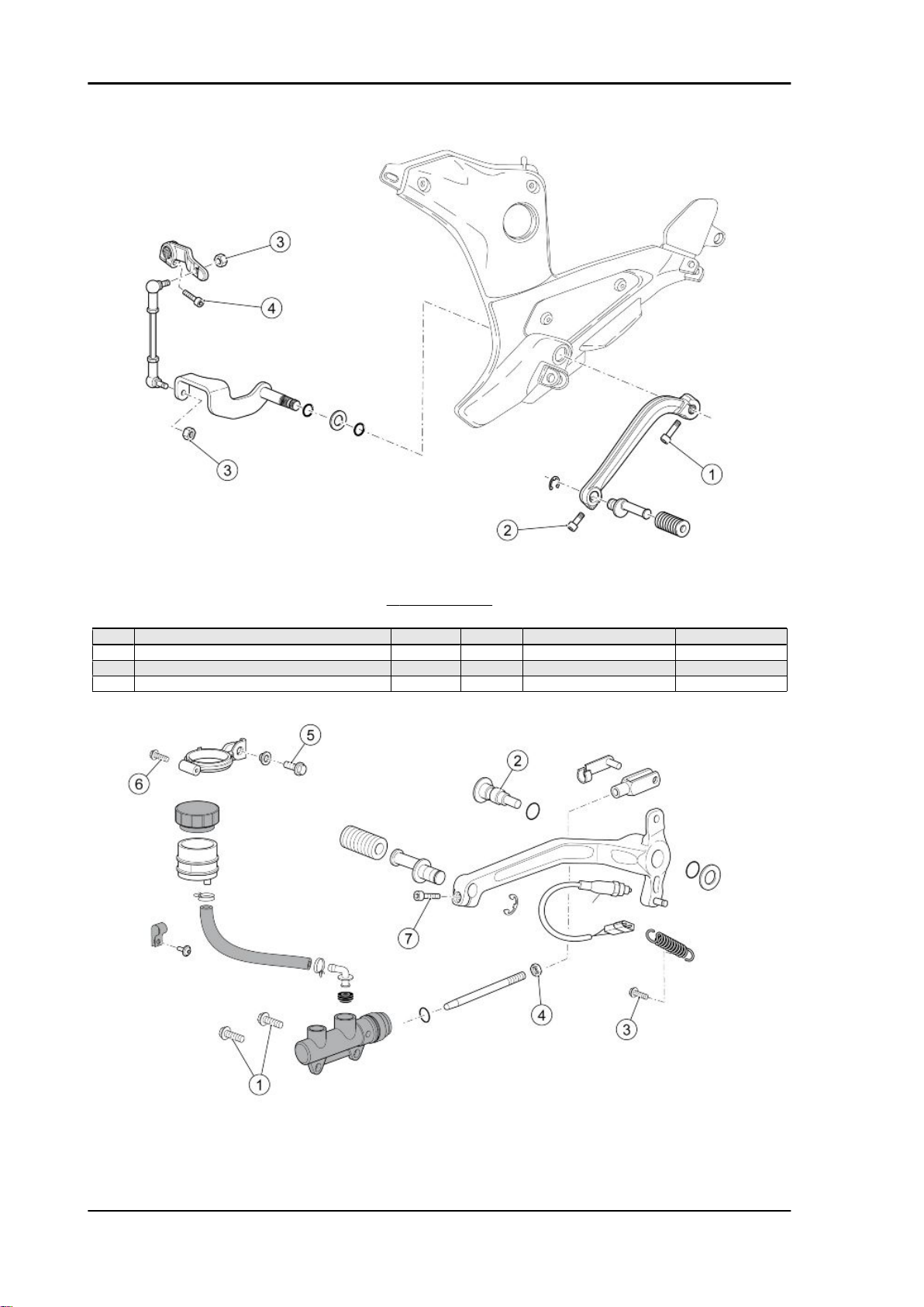
GEAR CONTROL
pos.
1 Gearbox lever fixing screws M6x20 1 10 Nm (7.37 lbf ft) 2 Peg to lever locking screw M6x16 1 10 Nm (7.37 lbf ft) 3 Rod fixing nut M6 2 10 Nm (7.37 lbf ft) 4 Transmission lever on the gear locking screw M6x20 1 10 Nm (7.37 lbf ft) -
Description Type Quantity Torque Notes
CHAR - 24
Norge GT 8v Characteristics
Revente Interdite - Revendita Vietata - Resaling Forbiden - Wiederverkauf Verboten
REAR BRAKE LEVER
pos. Description Type Quantity Torque Notes
1 Rear brake pump fixing screw M6x20 2 10 Nm (7.37 lbf ft) Loctite 243
2 Rear brake pedal fixing screw M8 1 15 Nm (11.06 lbf ft) Loctite 243
3 Spring on the brake pedal return fixing screw M5x16 1 6 Nm (4.42 lbf ft) 4 Lock nut on the rear brake pump rod M6 1 - Manually screw
5 Rear brake tank support fixing screw M6 1 10 Nm (7.37 lbf ft) 6 Rear brake tank support clamping screw SWP
M5x20
7 Peg to lever fixing screw M6x16 1 10 Nm (7.37 lbf ft) -
1 3 Nm (2.21 lbf ft) -
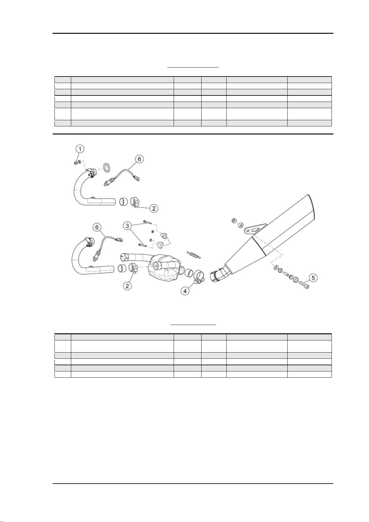
EXHAUST SYSTEM
pos.
1 Exhaust pipe fixing nut to the engine M8 4 25 Nm (18.44 lbf ft) 2 Exhaust pipe fixing clamp screw to the com-
3 Compensator fixing screw to the plate M10 2 25 Nm (18.44 lbf ft) 4 Compensator fixing clamp screw to the muffler M8 1 20 Nm (14.75 lbf ft) Clamp
5 Muffler fixing screw to the support M8x45 1 25 Nm (18.44 lbf ft) 6 Lambda sensor on the exhaust pipe M18 2 38 Nm (28.03 lbf ft) -
Description Type Quantity Torque Notes
M6 2 20 Nm (14.75 lbf ft) Clamp
pensator
CHAR - 25
Characteristics Norge GT 8v
Revente Interdite - Revendita Vietata - Resaling Forbiden - Wiederverkauf Verboten
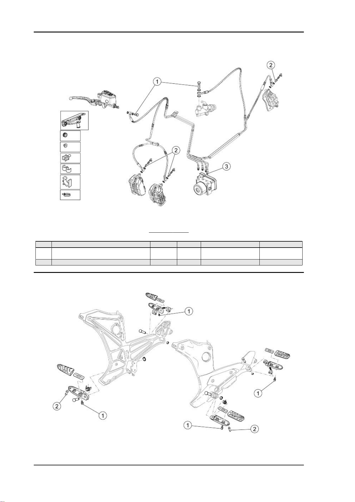
BRAKE SYSTEM
pos.
1 Brake pipe slot screw on the pump M10 2 25 Nm (18.44 lbf ft) 2 Joint with brake pipes retainer bleeding on the
3 Brake pipes joint on the ABS hydraulic unit - 4 25 Nm (18.44 lbf ft) -
Description Type Quantity Torque Notes
M10 3 25 Nm (18.44 lbf ft) -
calliper
CHAR - 26
Norge GT 8v Characteristics
Revente Interdite - Revendita Vietata - Resaling Forbiden - Wiederverkauf Verboten
FOOTRESTS
pos. Description Type Quantity Torque Notes
1 Rubber footrest fixing screw M6 8 10 Nm (7.37 lbf ft) Loctite 243
2 Rider footrest friction pin M8 2 25 Nm (18.44 lbf ft) Loctite 243
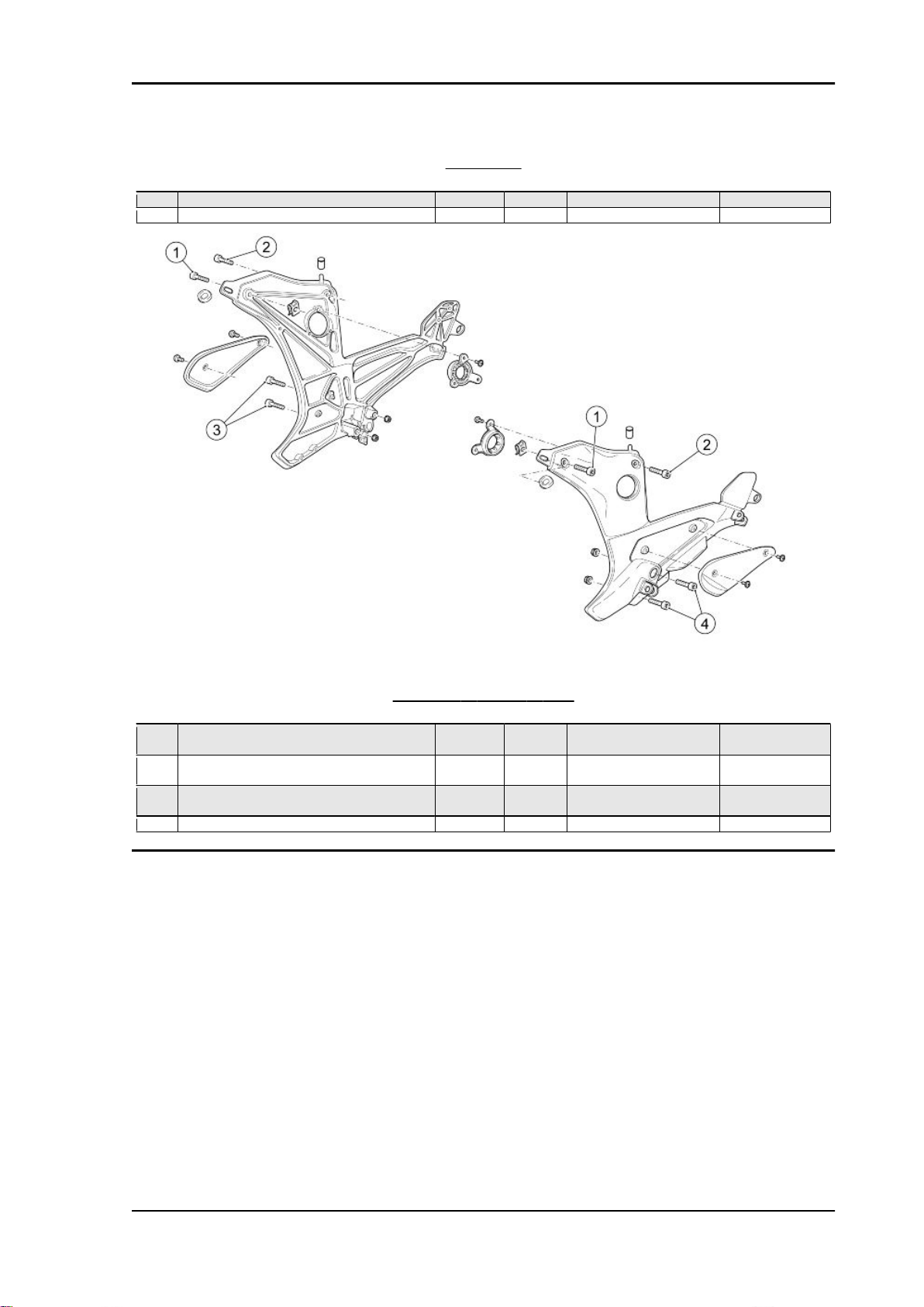
FOOTREST SUPPORT PLATE
pos.
1 Footrest plate to chassis front upper fixing
2 Footrest plate to chassis rear upper fixing
3 Right footrest plate to chassis lower fixing
4 Left footrest plate to chassis lower fixing screw M8x55 2 25 Nm (18.44 lbf ft) -
Description Type Quantity Torque Notes
M8x30 4 20 Nm (14.75 lbf ft) Loctite 243
screw
M8x25 4 25 Nm (18.44 lbf ft) Loctite 243
screw
M8x40 2 25 Nm (18.44 lbf ft) -
screw
CHAR - 27
Characteristics Norge GT 8v
Revente Interdite - Revendita Vietata - Resaling Forbiden - Wiederverkauf Verboten
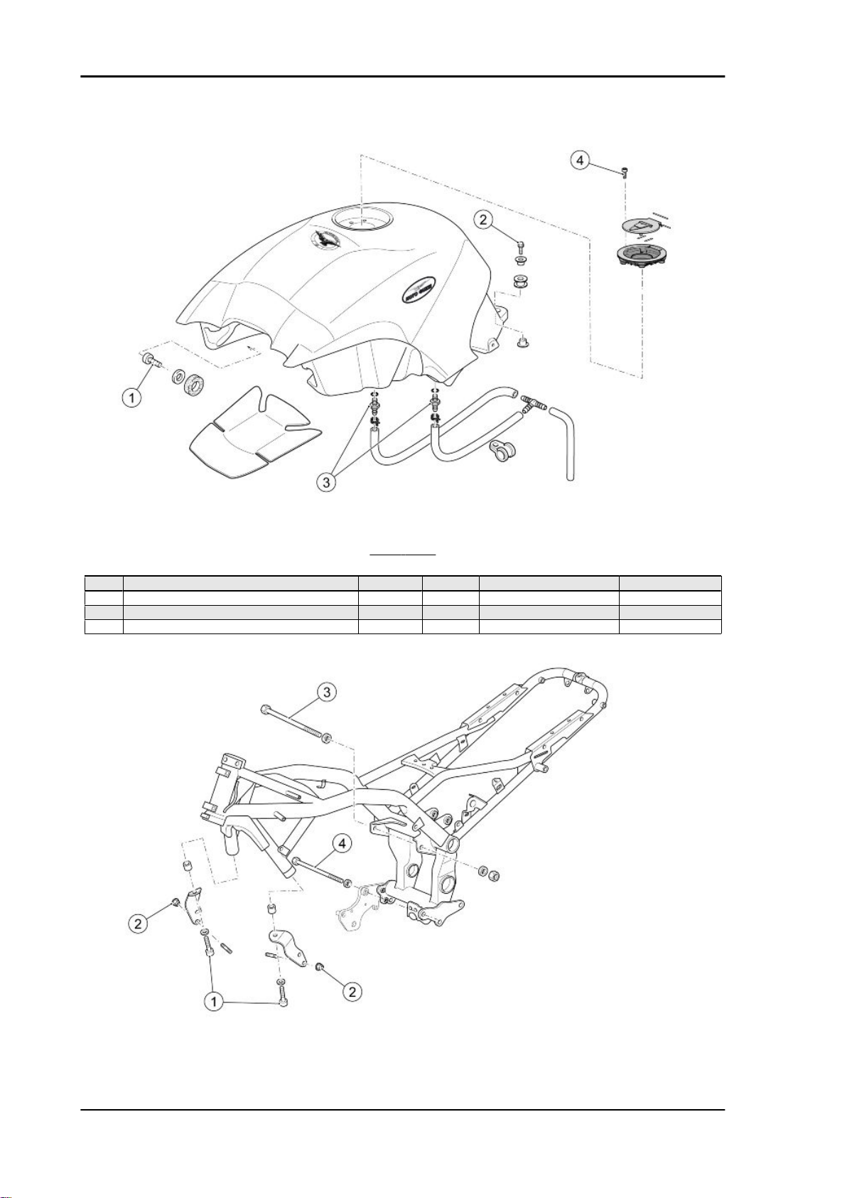
FUEL TANK
pos.
1 Tank to chassis front fixing screw M8 2 25 Nm (18.44 lbf ft) 2 Tank to chassis rear fixing screw M8 1 25 Nm (18.44 lbf ft) 3 Tank breather joint M6 2 6 Nm (4.42 lbf ft) 4 Filler to tank fixing screw M5 4 4 Nm (2.95 lbf ft) -
Description Type Quantity Torque Notes
CHAR - 28
Norge GT 8v Characteristics
Revente Interdite - Revendita Vietata - Resaling Forbiden - Wiederverkauf Verboten
FRAME
pos. Description Type Quantity Torque Notes
1 Plate to chassis fixing screw M12x50 2 50 Nm (36.87 lbf ft) 2 Plate to engine fixing nut M10 4 80 Nm (59 lbf ft) 3 Gear to chassis upper fixing pin M12 1 80 Nm (59 lbf ft) 4 Gear to chassis lower fixing pin M12x270 1 80 Nm (59 lbf ft) -
Back side
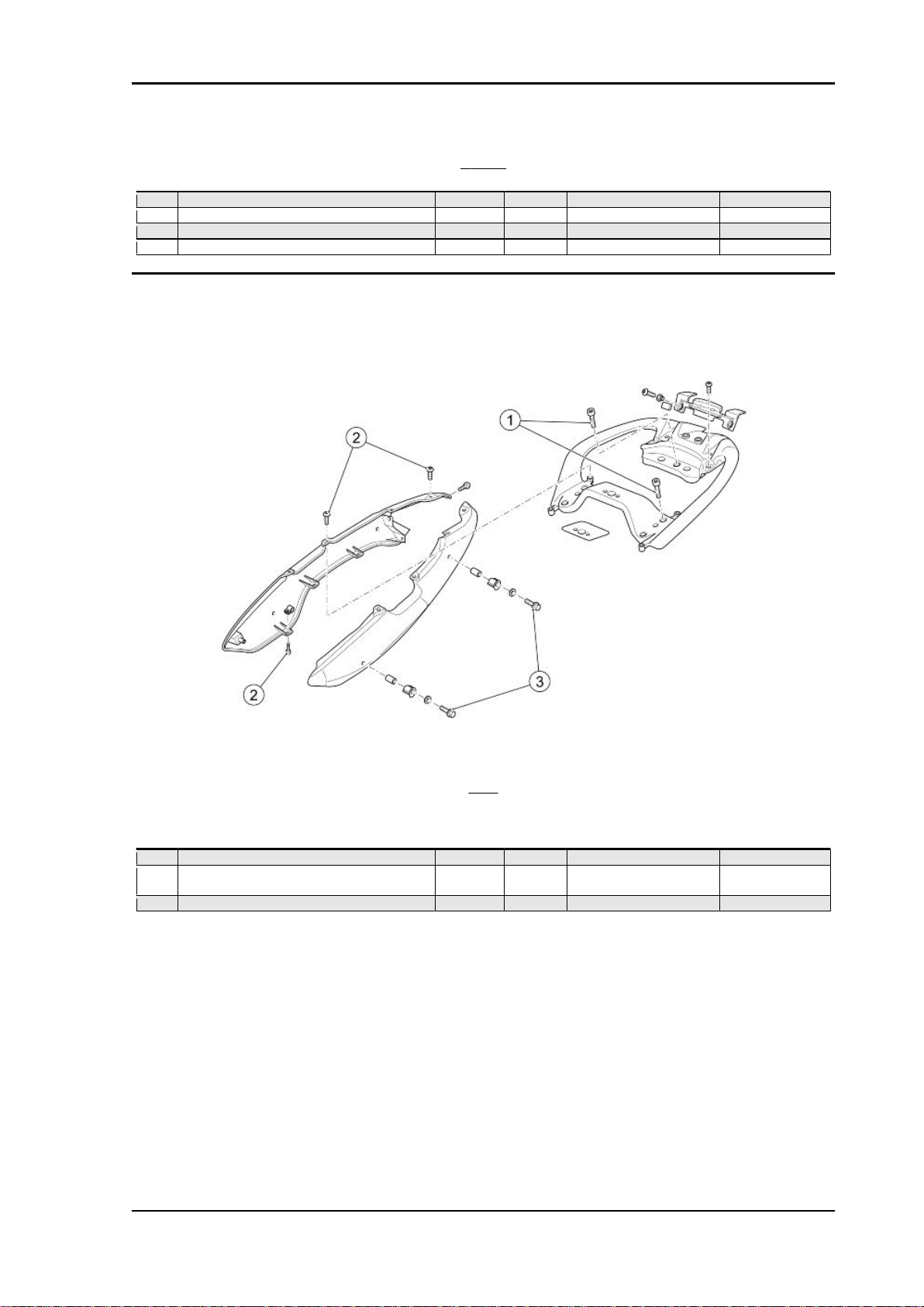
TAIL
Tail
pos.
1 Handgrip to chassis fixing screw M8x25 5 25 Nm (18.44ft) 2 Tail to handgrip and to rear fairings fixing
3 Hooks and tail fairing to chassis fixing screw M8 4 20 Nm (14.75 lbf ft) -
Description Type Quantity Torque Notes
M5x9 10 4 Nm (2.95 lbf ft) -
screw
CHAR - 29
Characteristics Norge GT 8v
Revente Interdite - Revendita Vietata - Resaling Forbiden - Wiederverkauf Verboten
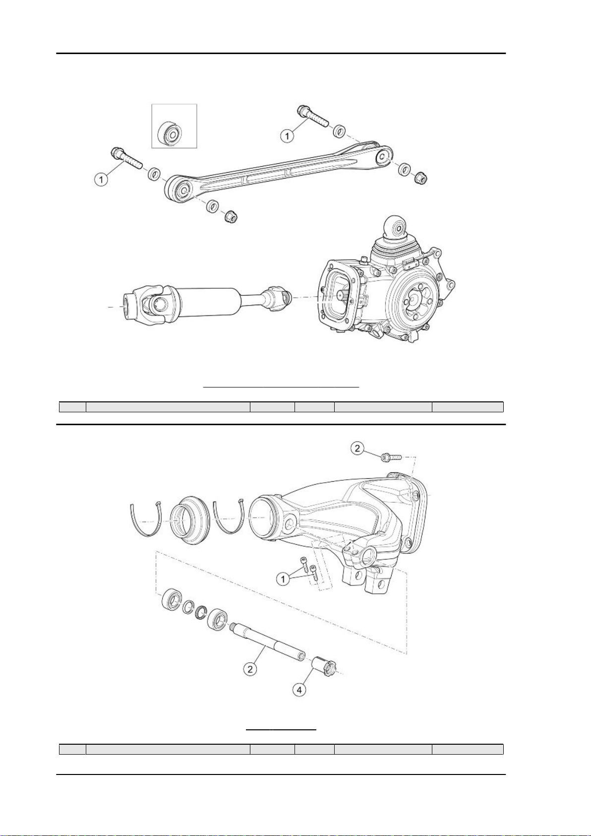
TRANSMISSION CONNECTION - ENGINE
pos.
1 Reaction rod fixing screw M10x55 2 50 Nm (36.87 lbf ft) -
Description Type Quantity Torque Notes
REAR SWINGARM
pos.
1 Swingarm clamp fixing screw on the bushing M6x25 2 10 Nm (7.37 lbf ft) -
CHAR - 30
Description Type Quantity Torque Notes
 Loading...