


Il contenuto del presente Manuale non è impegnativo e la Moto Guzzi S.p.A. si riserva perciò il diritto, ove
se ne presentasse la necessità, di apportare modifiche a particolari, accessori, attrezzi, ecc. che essa
ritenesse convenienti per lo scopo di miglioramento o per qualsiasi esigenza di carattere tecnico - commerciale oppure per adeguamento ai requisiti di legge dei diversi Paesi senza peraltro impegnarsi di aggiornare tempestivamente questo Manuale.
The contents of this Manual are not binding; Moto Guzzi S.p.A. therefore reserves the right to make
changes to parts, accessories, tools, etc. whenever it deems necessary in order to make improvements or
for any whatsoever technical – commercial requirements, or to comply with the provisions of the law in
individual countries, without, however, undertaking to update this Manual promptly.
MOTO GUZZI S.p.A.
Via E.V. Parodi, 57 23826 Mandello del Lario (LECCO) Italy
SERVIZIO PUBBLICAZIONE TECNICHE /
Cod. 31 92 01 83
Impianto DECA Ravenna
Stampato in Italia /
Printed in Italy
500 K - 06/02
TECHNICAL PUBBLICATIONS
da GraficheCola Lecco

PREMESSA
FOREWORD
- Questo manuale fornisce le informazioni essenziali per
le procedure di normale intervento sul veicolo.
- Le informazioni e le illustrazioni che compongono questo manuale, sono aggiornate al momento della divulgazione del manuale stesso.
- Questa pubblicazione è indirizzata ai Concessionari
Moto Guzzi S.p.A. e ai loro meccanici qualificati; molte
nozioni sono state volutamente omesse, perché giudicate superflue.
Non essendo possibile includere nozioni meccaniche
complete in questa pubblicazione, le persone che utilizzano questo manuale devono essere in possesso sia di
una preparazione meccanica di base, che di una conoscenza sulle procedure inerenti ai sistemi di riparazione
dei motoveicoli.
Senza queste conoscenze, la riparazione o il controllo
del veicolo potrebbe essere inefficiente o pericolosa.
Non essendo descritte dettagliatamente tutte le procedure per la riparazione, e il controllo del veicolo, bisogna adottare particolare attenzione al fine di evitare danni
ai componenti e alle persone. Per offrire al cliente maggiore soddisfazione dall’uso del veicolo, Moto Guzzi
S.p.A. si impegna a migliorare continuamente i propri
prodotti e la relativa documentazione. Le principali modifiche tecniche e modifiche alle procedure per le riparazioni del veicolo vengono comunicate a tutti i Punti Vendita Moto Guzzi S.p.A. e alle Filiali nel Mondo. Tali modifiche verranno apportate nelle edizioni successive di
questo manuale.
Per ulteriori informazioni vedi:
- MANUALE OFFICINA COD. 23 92 01 80
- CATALOGO RICAMBI COD. 31 92 00 83
La ditta Moto Guzzi S.p.A. si riserva il diritto di apportare modifiche in qualsiasi momento ai propri modelli, fermo restando le caratteristiche essenziali qui descritte e
illustrate.
I diritti di memorizzazione elettronica, di riproduzione e
di adattamento totale o parziale, con qualsiasi mezzo
sono riservati per tutti i Paesi.
- This manual provides the information required for normal
servicing of the motorcycle.
- The information and illustrations in this manual are up
to date at the time of going to press.
- This manual is intended for use by Moto Guzzi S.p.A.
Dealers and their qualified mechanics. Certain
information has been omitted intentionally, as this manual
does not purport to provide a comprehensive treatise on
mechanics.
The persons who use this manual must be fully
conversant with the basics of mechanics and with the
basic procedures of motorcycle repair.
Repairing or inspecting a motorcycle when one does not
possess such basic knowledge or training could result in
improper servicing and make the motorcycle unsafe to
ride.
For the same reason, certain basic precautions have
been omitted in the descriptions of repair and inspection
procedures; you are therefore invited to take special care
to avoid damage to motorcycle components or injury to
persons. Moto Guzzi S.p.A.’s mission is to enhance the
riding pleasure of end users through on-going
improvement of its products as well as of the relevant
technical literature. All Moto Guzzi S.p.A. Points of Sale
and Branches worldwide are kept updated on major
engineering changes and modifications to repair
procedures. Such changes and modifications are
reflected in successive releases of this manual.
For more details see:
- WORKSHOP MANUAL PART NUMBER 23 92 01 81
- SPARE PARTS CATALOGUE
PART NUMBER 31 92 00 83
Moto Guzzi S.p.A. reserves the right to make changes
to its products at any time, barring any such changes as
may alter the essential features of a product as specified
in this manual.
All rights of storage using electronic means, reproduction
and total or partial adaptation, whatever the means
adopted, are reserved in all countries.

NEVADA 750
NEVADA 750 CLUB

INDICE DELLE SEZIONI
INDEX FOR THE SECTIONS
I

SEZ. 1 INFORMAZIONI GENERALI PAG.
1 ABBREVIAZIONI E SIMBOLOGIA ................. 2
2 NORME GENERALI DI SICUREZZA.............. 2
SECT. 1 GENERAL INFORMATION PAG.
1 ABBREVIATIONS AND SYMBOLS ................ 2
2 GENERAL SAFETY PRESCRIPTIONS ......... 2
SEZ. 2 CARATTERISTICHE GENERALI
1 MOTORE ........................................................ 2
2 TRASMISSIONI .............................................. 3
3 TELAIO ........................................................... 3
4 DATI DI IDENTIFICAZIONE ........................... 5
SEZ. 3 LUBRIFICANTI E RIFORNIMENTI
1 OLIO MOTORE............................................... 2
2 TABELLA RIFORNIMENTI ............................. 2
SEZ. 4 PROGRAMMA DI MANUTENZIONE
1 PROGRAMMA DI MANUTENZIONE .............. 2
SEZ. 5 ATTREZZATURA SPECIFICA
COPPIE DI SERRAGGIO
E
1 ATTREZZATURA SPECIFICA ........................ 2
2 COPPIE DI SERRAGGIO ............................... 4
SEZ. 6 DATI DI CONTROLLO
1 SELEZIONATURA DEI CILINDRI E................ 2
PISTONI.......................................................... 2
2 QUOTE DI CONTROLLO PISTONE -
FASCE - SPINOTTO ....................................... 3
3 VALVOLE ........................................................ 4
4 SEDI VALVOLE .............................................. 5
5 MOLLE VALVOLE ........................................... 6
6 SISTEMA DI DISTRIBUZIONE ....................... 7
7 BIELLE ............................................................ 8
8 ALBERO MOTORE......................................... 9
9 POMPA OLIO ................................................ 10
SECT. 2 GENERAL FEATURES 1
1 ENGINE .......................................................... 2
2 TRANSMISSION............................................. 3
3 FRAME ........................................................... 3
4 IDENTIFICATION DATA.................................. 5
SECT. 3 LUBRICANTS AND SUPPLIES
1 ENGINE OIL ................................................... 2
2 LIQUID SUPPLIES CHART ............................ 2
SECT. 4 MAINTENANCE PROGRAMME
1 SERVICE SCHEDULE.................................... 3
SECT. 5 SPECIFIC TOOLS
TIGHTENING TORQUES
AND
1 SPECIFIC TOOLS .......................................... 2
2 TIGHTENING TORQUES ............................... 5
SECT. 6 CHECK DATA
1 CYLINDERS AND PISTONS SELECTION ..... 2
2 PISTON – PISTON RINGS – GUDGEON
PIN CHECKING DIMENSIONS ...................... 3
3 VALVES .......................................................... 4
4 VALVE SEATS ................................................ 5
5 VALVE SPRINGS ........................................... 6
6 TIMING SYSTEM............................................ 7
7 CONNECTING RODS .................................... 8
8 CRANKSHAFT................................................ 9
9 OIL PUMP ..................................................... 10
SEZ. 7 OPERAZIONI DI CONTROLLO
MANUTENZIONE
E
1 FRIZIONE ....................................................... 2
2 POMPA OLIO .................................................. 3
3 VALVOLA REGOLAZIONE PRESSIONE
OLIO ............................................................... 4
4 CARBURATORI .............................................. 5
5 ACCENSIONE ELETTRONICA MAGNETI
MARELLI “DIGIPLEX”................................... 11
6 CANDELE (FIG. 07-12) ................................ 13
7 ALTERNATORE - REGOLATORE
DUCATI ......................................................... 14
8 MOTORINO AVVIAMENTO (VALEO)........... 17
9 BATTERIA ..................................................... 18
10 CONTROLLO/SOSTITUZIONE PASTIGLIE
FRENI ........................................................... 21
11 REGOLAZIONE TENSIONE RAGGI
RUOTA .......................................................... 24
SECT. 7 INSPECTION AND MAINTENANCE
OPERATIONS
1 CLUTCH ......................................................... 2
2 OIL PUMP ....................................................... 3
3 OIL PRESSURE CONTROL VALVE ............... 4
4 CARBURETTORS .......................................... 5
5 MAGNETI MARELLI “DIGIPLEX”
ELECTRONIC IGNITION .............................. 11
6 SPARK PLUGS (FIG. 07-12) ........................ 13
7 DUCATI ALTERNATOR – REGULATOR ...... 14
8 STARTER MOTOR (VALEO) ........................ 17
9 BATTERY ...................................................... 18
10 BRAKE PAD CHECK/REPLACEMENT ........ 21
11 ADJUSTING WHEEL SPOKE TENSION...... 24
II
INDICE DELLE SEZIONI INDEX FOR THE SECTIONS

SEZ. 8 FORECELLA ANTERIORE
SOSTITUZIONE OLIO - REVISIONE
1 FORCELLA ANTERIORE ............................... 2
2 RIMOZIONE STELO ....................................... 4
3 INCONVENIENTI - CAUSE - RIMEDI ............ 5
4 SOSTITUZIONE OLIO FORCELLA
ANTERIORE ................................................... 6
5 SCOMPOSIZIONE / REVISIONE ................... 8
6 REVISIONE POMPANTE ............................. 11
7 RICOMPOSIZIONE ...................................... 12
SECT. 8 FRONT FORK
OIL CHANGE - OVERHAUL
1 FRONT FORK ................................................. 2
2 FORK LEG REMOVAL ................................... 4
3 PROBLEMS – CAUSES - SOLUTIONS ......... 5
4 FRONT FORK OIL CHANGE.......................... 6
5 DISASSEMBLY / OVERHAUL ........................ 8
6 PLUNGER OVERHAUL ................................ 11
7 REASSEMBLY.............................................. 12
SEZ. 9 SCHEMA IMPIANTO ELETTRICO
1 LEGENDA SCHEMA IMPIANTO
ELETTRICO “DUCATI” FINO AL TELAIO
N. LK 111944 .................................................. 3
2 LEGENDA SCHEMA IMPIANTO
ELETTRICO “SHINDENGEN” DAL TELAIO
N. LK 111945 .................................................. 5
3 MORSETTIERA PORTA FUSIBILI .................. 6
SEZ. 10 SEQUENZE DI SMONTAGGIO/
RIMONTAGGIO
1 POMPA OLIO .................................................. 2
2 VALVOLA REGOLAZIONE PRESSIONE
OLIO ............................................................... 3
3 ALTERNATORE “DUCATI” ............................. 4
4 IMPIANTO DI SCARICO................................. 5
4A SILENZIATORI ............................................... 5
4B TUBI DI SCARICO .......................................... 6
4C CAMERA DI ESPANSIONE ................................. 6
5 SERBATOIO CARBURANTE ......................... 7
6 SELLE ............................................................. 8
6A SELLA ANTERIORE (VERSIONE “BASE”) “B” ........ 8
6B SELLA POSTERIORE (VERSIONE “BASE”) “E” ...... 8
6C SELLA UNICA (VERSIONE “CLUB”) “F” ............... 8
7 PARAFANGHI ................................................. 9
7A PARAFANGO ANTERIORE ............................... 9
7B PARAFANGO POSTERIORE E PORTATARGA ...... 10
8 RUOTA ANTERIORE .................................... 11
9 RUOTA POSTERIORE ................................. 13
10 MANUBRIO................................................... 14
11 CRUSCOTTO ............................................... 15
SECT. 9 WIRING DIAGRAM
1 KEY TO WIRING DIAGRAM “DUCATI” UP TO
FRAME NO. LK 111944 .................................. 3
2 KEY TO WIRING DIAGRAM “SHINDENGEN”
FROM FRAME NO. LK 111945 ...................... 5
3 FUSE TERMINAL BLOCK .............................. 6
SECT. 10 DISASSEMBLY/
REASSEMBLY SEQUENCES
1 OIL PUMP ....................................................... 2
2 OIL PRESSURE CONTROL VALVE ............... 3
3 “DUCATI” ALTERNATOR ................................ 4
4 EXHAUST SYSTEM ....................................... 5
4A SILENCERS .................................................. 5
4B EXHAUST PIPES ............................................ 6
4C EXPANSION CHAMBER .................................... 6
5 FUEL TANK..................................................... 7
6 SEATS ............................................................ 8
6A FRONT SEAT (“STANDARD” VERSION) “B” .......... 8
6B REAR SEAT (“STANDARD” VERSION) “E” ........... 8
6C ONE-PIECE SEAT (“CLUB” VERSION) “F” ........... 8
7 MUDGUARDS ................................................ 9
7A FRONT MUDGUARDS ..................................... 9
7B REAR MUDGUARD AND REGISTRATION PLATE
HOLDER
8 FRONT WHEEL ............................................ 11
9 REAR WHEEL .............................................. 13
10 HANDLEBARS.............................................. 14
11 DASHBOARD ............................................... 15
.................................................... 10
INDICE DELLE SEZIONI INDEX FOR THE SECTIONS
III

IV

INFORMAZIONI GENERALI
GENERAL INFORMATION
1
2
3
4
5
6
7
8
9
10
1
1 ABBREVIAZIONI E SIMBOLOGIA
1 ABBREVIATIONS AND SYMBOLS
Allo scopo di rendere la lettura di immediata comprensione i paragrafi sono stati contraddistinti da illustrazioni
1
schematiche che evidenziano l’argomento trattato.
In questo manuale sono state riportate note informative
con significati particolari:
Norme antinfortunistiche per l’operatore e per
2
chi opera nelle vicinanze.
Esiste la possibilità di arrecare danno al veicolo e/o ai suoi componenti.
Ulteriori notizie inerenti l’operazione in corso
3
N.B. La “destra” o la “sinistra” é riferita ai comandi visti dalla posizione di guida.
N.B. Tutti i disegni tecnici del manuale utilizzano misure espresse in mm. e coppie di serraggio
4
espresse in Nm.
In order to optimise the clarity of this manual, the headings are marked by schematic illustrations summarising
the relative subject matter.
This manual contains informative notes with specific
meanings:
Safety prescriptions for the operator and persons working in the area.
Risk of damaging the motorcycle and/or its
parts.
Further information concerning the current task
N.B. The indications “right” or “left” refer to the
controls viewed from the riding position.
N.B. All technical drawings in the manual use
measurements in mm and tightening torques
in Nm.
5
2 NORME GENERALI DI SICUREZZA
OSSIDO DI CARBONIO
Se è necessario far funzionare il motore per poter effet-
6
tuare qualche operazione, assicurarsi che questo avvenga in uno spazio aperto o in un locale ben ventilato.
Non fare mai funzionare il motore in spazi chiusi.
Se si opera in uno spazio chiuso. Utilizzare un sistema
di evacuazione dei fumi di scarico.
7
8
9
PERICOLO
I fumi di scarico contengono ossido di carbonio,
un gas velenoso che può provocare la perdita
di conoscenza e anche la morte.
Far funzionare il motore in uno spazio aperto o, se si
opera in uno spazio chiuso, utilizzare un sistema di evacuazione dei fumi di scarico.
CARBURANTE
Operare in uno spazio ben ventilato. Tenere sigarette,
fiamme o fonti di scintille lontano dalla zona di lavoro e
dalla zona in cui il carburante viene conservato.
2 GENERAL SAFETY PRESCRIPTIONS
CARBON MONOXIDE
When an operation must be performed with the engine
running, position the motorcycle outdoors or in a wellventilated area.
Never run the engine in an enclosed place.
If running the engine indoors use an extraction system
for the exhaust gas.
DANGER
Exhaust emissions contain carbon monoxide,
a poisonous gas that may cause loss of consciousness or even death.
Run the engine outdoors or, if working indoors, use an
exhaust emission extraction system.
FUEL
Work in a well-ventilated area. Keep cigarettes, flames,
and sources of sparks well clear of the work area and
the area in which fuel is stored.
10
PERICOLO
Il carburante è altamente infiammabile e in al-
cune condizioni diventa esplosivo.
TENERE LONTANO DALLA PORTATA DEI BAM-
BINI.
2
INFORMAZIONI GENERALI
DANGER
Fuel is highly flammable and may assume ex-
plosive properties in certain circumstances.
KEEP AWAY FROM CHILDREN.
GENERAL INFORMATION
COMPONENTI AD ALTE TEMPERATURE
PERICOLO
Il motore e i componenti dell’impianto di scari-
co diventano molto caldi e rimangono caldi per
un certo periodo anche dopo che il motore è
stato spento. Prima di maneggiare questi componenti, indossare guanti isolanti o attendere
fino a che il motore e l’impianto di scarico si
sono raffreddati.
COMPONENTS AT HIGH TEMPERATURES
DANGER
The engine and exhaust component parts be-
come hot when the engine is running and will
stay hot for some time after the engine has been
stopped. Wear heat insulated gloves before handling these components or allow time for the
engine and exhaust system to cool down before proceeding.
1
2
OLIO MOTORE ESAUSTO
PERICOLO
Utilizzare guanti in lattice per le operazioni di
manutenzione che prevedono il contatto con
l’olio. L’olio esausto del motore, se viene
ripetutamente lasciato a contatto con la pelle
per periodi prolungati, può causare il cancro
della pelle. Sebbene questo sia improbabile, a
meno che non si maneggi olio esausto quotidianamente, si consiglia di lavare le mani accuratamente con acqua e sapone nel caso venga
maneggiato.
TENERE LONTANO DALLA PORTATA DEI BAMBINI.
PRECAUZIONI E INFORMAZIONI GENERALI
Per garantire che il veicolo sia sempre in perfette
condizioni di funzionamento è necessario attenersi
alle istruzioni fornite nel programma di manutenzione periodica descritto nella sezione 4.
La prima serie di operazioni di manutenzione è da
eseguire dopo 1500 Km come riportato nella tabella del cap. 1 della sez. 4; l’esecuzione di tali operazioni è importantissima in quanto consentono di
controllare l’usura iniziale che avviene in corrispondenza del rodaggio.
E’ inoltre importante quando si esegue la riparazione, lo smontaggio e il rimontaggio del veicolo attenersi scrupolosamente alle seguenti raccomandazioni.
SPENT ENGINE OIL
DANGER
Wear rubber gloves for maintenance work that
involves contact with oil. If left repeatedly in
contact with the skin for prolonged periods,
spent engine oil may cause skin cancer. Even
though this eventuality is remote unless spent
oil is handled daily, it is advisable to wash the
hands thoroughly with soap and water after
handling spent oil.
KEEP AWAY FROM CHILDREN.
GENERAL PRECAUTIONS AND INFORMATION
To ensure that the motorcycle is in perfect running
order adhere strictly to the instructions provided in
the periodic maintenance programme described in
section 4.
The first series of maintenance operations must be
performed after 1500 km (1000 miles) as indicated
in chap. 1 of section 4; execution of these operations is of the maximum importance because they
make it possible to check initial wear sustained
during running in.
It is also important to adhere strictly to the following
instructions when repairing, disassembling or reassembling the motorcycle or its components.
3
4
5
6
7
PERICOLO
Per qualsiasi tipo di operazione è vietato l’uso
di viva fiamma.
Prima di iniziare qualsiasi intervento di manutenzione o ispezione al veicolo, arrestare il motore e togliere la chiave, attendere che motore
e impianto di scarico si siano raffreddati, sollevare possibilmente il veicolo, con apposita attrezzatura, su pavimento solido e in piano.
Porre particolare attenzione alle parti ancora
calde del motore e dell’impianto di scarico, in
modo tale da evitare ustioni.
Il veicolo è costruito con parti non commestibili; non mordere, succhiare, masticare o ingerire nessuna parte dello stesso per nessun motivo.
Se non espressamente descritto, il rimontaggio
dei gruppi segue in senso inverso le operazioni
di smontaggio.
INFORMAZIONI GENERALI GENERAL INFORMATION
DANGER
Using bare flames is strictly forbidden when
working on the motorcycle.
Before servicing or inspecting the motorcycle:
stop the engine and remove the key from the
ignition switch; allow the engine and exhaust
system to cool down; where possible, lift the
motorcycle using adequate equipment placed
on firm and level ground.
Pay particular attention to any parts of the engine or exhaust system that may still be hot to
the touch to avoid burns.
No parts of the motorcycle are edible; do not
bite, suck, chew, or swallow any of the parts for
any whatsoever reason.
If not expressly indicated otherwise, for the
reassembly of the units repeat the disassembly
operations in reverse order.
8
9
10
3
1
2
L’eventuale sovrapposizione di operazioni nei
vari rimandi ad altri capitoli deve essere interpretata con logica, evitando così rimozioni non
necessarie di componenti.
Non utilizzare mai il carburante come solvente
per la pulizia del veicolo.
Scollegare il cavo negativo () della batteria, in
caso si debbano eseguire saldature elettriche.
Quando due o più persone lavorano contemporaneamente, prestare attenzione alla sicurezza di ciascuno.
Where a procedure is cross-referred to relevant
sections in the manual, proceed sensibly to
avoid disturbing any parts unless strictly necessary.
Never use fuel instead of solvent to clean the
motorcycle.
Always disconnect the battery negative (–) lead
before soldering any electrical components.
When two or more persons service the same
motorcycle together, special care must be taken
to avoid personal injury.
PRIMA DELLO SMONTAGGIO
- Rimuovere lo sporco, il fango, la polvere e i corpi estra-
3
nei dal veicolo prima dello smontaggio dei componenti.
- Impiegare, dove previsto, gli attrezzi speciali progettati
per questo veicolo.
SMONTAGGIO DEI COMPONENTI
- Contrassegnare le posizioni su tutti i giunti di connes-
4
5
sioni (tubi, cavi, ecc.) prima di dividerli e identificarli
con segni distintivi differenti.
Ogni pezzo va segnato chiaramente per poter essere
identificato in fase di installazione.
- Pulire e lavare accuratamente i componenti smontati,
con detergente a basso grado di infiammabilità.
- Tenere insieme le parti accoppiate tra di loro, perché si
sono “adattate” l’una all’altra in seguito alla normale
usura.
Alcuni componenti devono essere utilizzati assieme oppure sostituiti completamente.
- Tenersi lontani da fonti di calore.
6
RIMONTAGGIO DEI COMPONENTI
ATTENZIONE
Non riutilizzare mai un anello elastico, quando
viene smontato deve essere sostituito con uno
7
8
nuovo.
Quando si monta un anello elastico nuovo, fare
attenzione a non allontanare le sue estremità
più dello stretto necessario per infilarlo sull’albero.
Dopo il montaggio di un anello elastico, verificare che sia completamente e saldamente inserito nella sua sede.
PRIOR TO DISASSEMBLY
- Clean off all dirt, mud, and dust and remove any foreign objects from the motorcycle before disassembling
any components.
- Use model-specific special tools where specified.
DISASSEMBLING THE COMPONENTS
- Mark all connections (hoses, wiring, etc.) with their positions before disconnecting them. Identify each connection using a different symbol.
Mark each part clearly to avoid confusion when refitting.
Thoroughly clean and wash any components you have
removed using a detergent with low flash point.
- Keep connected parts together since they will have
seated themselves against one another as a result of
normal wear.
Certain components are matched-pair parts and should
always be used together or replaced as a set.
- Keep the motorcycle and its parts well away from heat
sources.
REASSEMBLING THE COMPONENTS
WARNING
Never reuse circlips or snap rings. These parts
must always be renewed once they have been
disassembled.
When fitting a new circlip or snap ring, open
the ends just sufficiently to allow fitment to the
shaft.
Make a rule to check that a newly–fitted circlip
or snap ring has located fully into its groove.
9
10
Non utilizzare aria compressa per la pulizia dei
cuscinetti.
IMPORTANTE:
I cuscinetti devono ruotare liberamente, senza
impuntamenti e/o rumorosità, altrimenti devono essere sostituiti.
4
INFORMAZIONI GENERALI
Never use compressed air to clean bearings.
IMPORTANT:
All bearings must rotate freely with no stiffness
or noise. Renew any bearings that do not meet
these requirements.
GENERAL INFORMATION

- Utilizzare esclusivamente RICAMBI ORIGINALI Moto
Guzzi.
- Attenersi all’impiego dei lubrificanti e del materiale di
consumo consigliato.
- Lubrificare le parti (quando è possibile) prima di rimontarle.
- Nel serraggio di viti e dadi, iniziare con quelli di diametro maggiore oppure quelli interni, procedendo in diagonale. Eseguire il serraggio con passaggi successivi,
prima di applicare la coppia di serraggio.
- Sostituire sempre le guarnizioni, gli anelli di tenuta, gli
anelli elastici, gli anelli O-Ring (OR) e le copiglie con
altri nuovi.
Pulire tutti i piani di giunzione, i bordi dei paraolio e le
guarnizioni prima del rimontaggio.
Applicare un leggero velo di grasso a base di litio sui
bordi dei paraolio.
Rimontare i paraolio e i cuscinetti con il marchio o numero di fabbricazione rivolti verso l’esterno (lato visibile).
Quando si montano i cuscinetti, lubrificarli abbondantemente.
- Controllare che ogni componente sia stato montato in
modo corretto.
- Dopo un intervento di riparazione o di manutenzione
periodica, effettuare i controlli preliminari e collaudare
il veicolo in una proprietà privata o in una zona a bassa
intensità di circolazione.
- Use genuine ORIGINAL Moto Guzzi SPARE PARTS
only.
- Use exclusively the recommended lubricants and
consumables.
- Wherever possible, lubricate parts before assembly.
- When tightening nuts and bolts, start with the largest or
innermost nut/bolt and proceed in a crosswise pattern.
Tighten evenly in subsequent steps until achieving the
specified torque.
- Always renew all gaskets, seals, circlips or snap rings,
O-rings and split pins.
Clean all mating surfaces, oil seal edges and gaskets
before assembly.
Apply a light coat of lithium grease along the edges of
oil seals.
Fit oil seals and bearings with the brand or serial number
facing outwards (in view).
Lubricate bearings abundantly before assembly.
- Make a rule to check that all components you have
fitted are correctly in place.
- After repairing the motorcycle and after each service
inspection, perform the preliminary checks, and then
road test the motorcycle in a private estate area or in a
safe area away from traffic.
1
2
3
4
5
6
7
8
9
INFORMAZIONI GENERALI GENERAL INFORMATION
10
5

1
2
3
4
5
6
7
8
9
10
6

CARATTERISTICHE GENERALI
GENERAL FEATURES
1
2
3
4
5
6
7
8
9
10
1

1 MOTORE
1 ENGINE
Ciclo ..................................................... a quattro tempi
N. cilindri .................................................................... 2
1
Disposizione cilindri.................................... a "V" di 90°
Alesaggio ......................................................... 80 mm
Corsa................................................................ 74 mm
Cilindrata totale ............................................. 743,9 cc
Rapporto di compressione ................................... 9,6:1
2
DISTRIBUZIONE
A valvole in testa con aste e bilancieri.
DATI DELLA DISTRIBUZIONE
ASPIRAZIONE:
■ apre 18° prima del P.M.S.
3
■ chiude 50° dopo il P.M.I.
SCARICO:
■ apre 53° prima del P.M.I.
■ chiude 15° dopo il P.M.S.
Gioco alle valvole per controllo messa in fase distribu-
4
zione: 1mm
Gioco di funzionamento tra bilancieri e valvole:
■ aspirazione: ................................................ 0,15 mm
■ scarico: ...................................................... 0,20 mm
Cycle ............................................................... 4-stroke
N. cylinders ................................................................ 2
Cylinder configuration .................................. 90° V-twin
Bore.................................................................. 80 mm
Stroke ................................................................ 74 mm
Capacity ......................................................... 743.9 cc
Compression ratio ................................................ 9.6:1
TIMING SYSTEM
Valve gear data
TIMING SYSTEM DATA
INTAKE:
■ Opens 18° before TDC
■ Closes 50° after BDC
EXHAUST:
■ Opens 53° before BDC
■ Closes 15° after TDC
Valve timing clearance check: 1 mm
Rocker arm/valve working clearance:
■ intake: ......................................................... 0.15 mm
■ exhaust: ...................................................... 0.20 mm
5
LUBRIFICAZIONE
Forzata con pompa a lobi e spia insufficiente pressione
situata sul cruscotto.
Filtri olio: a rete all'interno della coppa ed a cartuccia
sostituibile dall'esterno.
6
ACCENSIONE
Elettronica digitale a scarica induttiva “MAGNETI
MARELLI - DIGIPLEX”.
I tipi di candela da impiegare sono:
■ NGK-BRE8ES, CHAMPION-RN3C, BOSCH-WR4CC.
Distanza fra gli elettrodi: 0,7 mm
7
ALIMENTAZIONE
N. 2 carburatori Dell'Orto tipo "PHBH 30 BD/BS"
SCARICO
N. 2 tubi e N. 2 silenziatori collegati.
8
GENERATORE ALTERNATORE
Montato sulla parte anteriore dell'albero motore.
Potenza di uscita: 350W a 5000 giri (14V - 25A).
LUBRICATION
Pressure fed by gear pump with low oil warning lamp on
instrument panel.
Oil filters: wire mesh inside sump and replaceable
cartridge filter outside sump.
IGNITION
“MAGNETI MARELLI - DIGIPLEX” Inductive discharge
digital electronics.
We recommend the following types of spark plugs:
■ NGK-BRE8ES, CHAMPION-RN3C, BOSCH-WR4CC.
Spark plug gap: 0.7 mm
CARBURETORS
2 Dell’Orto carburetors “PHBH 30 BD/BS”
EXHAUST
2 pipes and 2 connected silencers.
GENERATOR/ALTERNATOR
On front of crankshaft.
Output power: 350W at 5000 rev/min (14V - 25A).
9
10
AVVIAMENTO
Elettrico mediante apposito motorino (12 V - 1,2 KW)
munito di innesto a comando elettromagnetico.
Comando a pulsante (START) " " posto sul lato destro
del manubrio.
2
CARATTERISTICHE GENERALI GENERAL FEATURES
STARTING
Electric starter motor (12 V - 1.2 kw) with electromagnetic
ratchet control.
(START) " " push-button on right handlebar.

2 TRASMISSIONI
2 TRANSMISSION
FRIZIONE
Tipo monodisco a secco con molla a diaframma; comando a mano con leva posta sul lato sinistro del manubrio.
TRASMISSIONE PRIMARIA
Ad ingranaggi, rapporto 1:3125 (Z=16/21).
CAMBIO
A 5 marce con ingranaggi sempre in presa ad innesto
frontale. Comando con leva posta al centro del motociclo
sul lato sinistro.
Rapporti cambio:
1a marcia = 1:2,3636 (Z=11/26)
2a marcia = 1:1,6428 (Z=14/23)
3a marcia = 1:1,2777 (Z=18/23)
4a marcia = 1:1,0555 (Z=18/19)
5a marcia = 1:0,9000 (Z=20/18)
TRASMISSIONE SECONDARIA
Ad albero con giunto cardanico e coppia conica.
Rapporto: 1:3,875 (Z=8/31).
Rapporti totali (motore-ruota):
1a marcia = 1:12,0213
2a marcia = 1: 8,3555
3a marcia = 1: 6,4987
4a marcia = 1: 5,3685
5a marcia = 1: 4,5773
CLUTCH
Single driven disk, dry type with spring; hand controlled
by lever on left-hand side of handlebars.
PRIMARY DRIVE
By gears, ratio 1:3125 (tooth ratio = 16/21).
TRANSMISSION
5 speeds, frontal engagement, constant mesh gears.
Pedal operated on central left-hand side of the
motorcycle.
Gear ratios:
1st gear = 1:2.3636 (Z = 11/26)
2ndgear = 1:1.6428 (Z = 14/23)
3rd gear = 1:1.2777 (Z = 18/23)
4th gear = 1:1.0555 (Z = 18/19)
5st gear = 1:0.9000 (Z = 20/18)
SECONDARY TRANSMISSION
By shaft, with universal joint and bevel gear.
Ratio: 1:3.875 (Z = 8/31).
Overall gear ratios (engine-wheel):
1st gear = 1:12.0213
2nd gear = 1: 8.3555
3rd gear = 1: 6.4987
4th gear = 1: 5.3685
5st gear = 1: 4.5773
1
2
3
4
5
3 TELAIO
Tubolare a doppia culla scomponibile in acciaio ad alto
limite di snervamento
SOSPENSIONI
Anteriore: forcella telescopica idraulica "MARZOCCHI",
Ø 40 mm.
Posteriore: forcellone oscillante presso fuso in lega leggera con due ammortizzatori regolabili nel precarico molle
e nella frenatura idraulica.
RUOTE
A raggi con cerchi in acciaio nelle misure:
■ anteriore: 2,15 x 18"
■ posteriore: 2,50 x 16"
PNEUMATICI
MICHELIN
Anteriore: 100/90 18-56V Macadam 50E
Posteriore: 130/90 16-65V Macadam
PIRELLI
Anteriore: 100/90 H18 MT69 E
Posteriore: 130/90 H16 MT68 E
METZELER
Anteriore: 100/90 V18 TL 56 V
Posteriore: 130/90 16 TL 67 V
3 FRAME
Tubular structure with dismountable double-cradle frame made of high yield stress steel
SUSPENSIONS
Front: “MARZOCCHI” hydraulic telescopic fork, Ø 40 mm.
Rear: die-cast swinging arm in light metal with two shock
absorbers with adjustable preloaded springs and
adjustable hydraulic braking.
WHEELS
Spoked, with steel rims.Rim sizes:
■ front: 2.15 x 18"
■ rear: 2.50 x 16"
TYRES
MICHELIN
Front: 100/90 18-56V Macadam 50E
Rear: 130/90 16-65V Macadam
PIRELLI
Front: 100/90 H18 MT69 E
Rear: 130/90 H16 MT68 E
METZELER
Front: 100/90 V18 TL 56 V
Rear: 130/90 16 TL 67 V
6
7
8
9
10
CARATTERISTICHE GENERALI GENERAL FEATURES
3
FRENI
Anteriore: disco flottante in acciaio inox brembo "serie
oro" con pinza fissa a 4 pistoncini differenziati.
1
Comando con leva a mano posta sul lato destro del
manubrio.
– Ø disco 320 mm
– Ø cilindro frenante 34/30 mm
– Ø pompa 13 mm
Posteriore: a disco fisso in acciaio inox con pinza a dop-
2
pio cilindro frenante. Comando con leva a pedale posta
al centro sul lato destro del motociclo.
– Ø disco 260 mm
– Ø cilindro frenante 32 mm
– Ø pompa 16 mm
3
INGOMBRI E PESO
Passo (a carico) ............................................ 1,482 m
Lunghezza massima ..................................... 2,205 m
Larghezza massima ........................................ 0,875 m
Altezza massima ............................................. 1,180 m
Altezza sella .................................................. 0,770 m
4
Peso a secco (versione Club) .......................... 182 kg
Peso a secco (versione base) .......................... 176 kg
BRAKES
Front: Brembo “Gold Series” floating disk in stainless steel
with fixed caliper and 4 separated pistons.
Brake hand lever on the right-hand side of the handlebar.
– Ø disk 320 mm
– Ø brake cylinder 34/30 mm
– Ø master cylinder 13 mm
Rear: stainless steel fixed disk with twin-piston brake
caliper. Brake pedal in the center on the right-hand side
of the motorbike.
– Ø disk 260 mm
– Ø brake cylinder 32 mm
– Ø master cylinder 16 mm
DIMENSIONS AND WEIGHT
Wheelbase (loaded) ........................................ 1.482 m
Overall length .................................................. 2.205 m
Overall width ................................................... 0.875 m
Height .............................................................. 1.180 m
Saddle height .................................................. 0.770 m
Dry weight (Club version) .................................. 182 kg
Dry weight (standard version) ........................... 176 kg
5
6
7
8
N.B. Il motoveicolo può essere equipaggiato a
richiesta con parabrezza che consente una guida confortevole, e borse asportabili.
Tutti questi volumi comportano però una limitazione all’aerodinamica del veicolo. E’
consigliabile pertanto, specie in condizioni di
carico massimo, non superare la velocità di 130
Km/h circa.
On request the motor vehicle can be equipped
with a windshield which allows comfortable
driving, and removable sidebags.
These items do however after the aerodynamic
features of the bike; it is advisable therefore not
to exceed 130 kph especially when the bike is
fully loaded.
9
10
4
CARATTERISTICHE GENERALI GENERAL FEATURES
4 DATI DI IDENTIFICAZIONE
4 IDENTIFICATION DATA
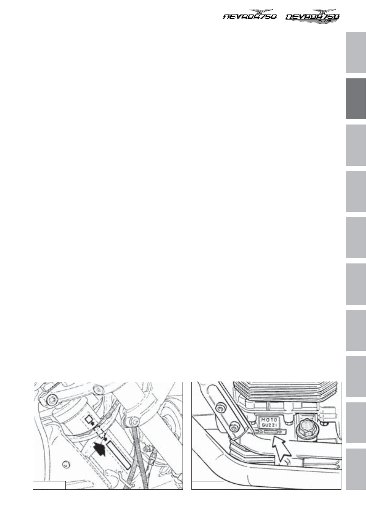
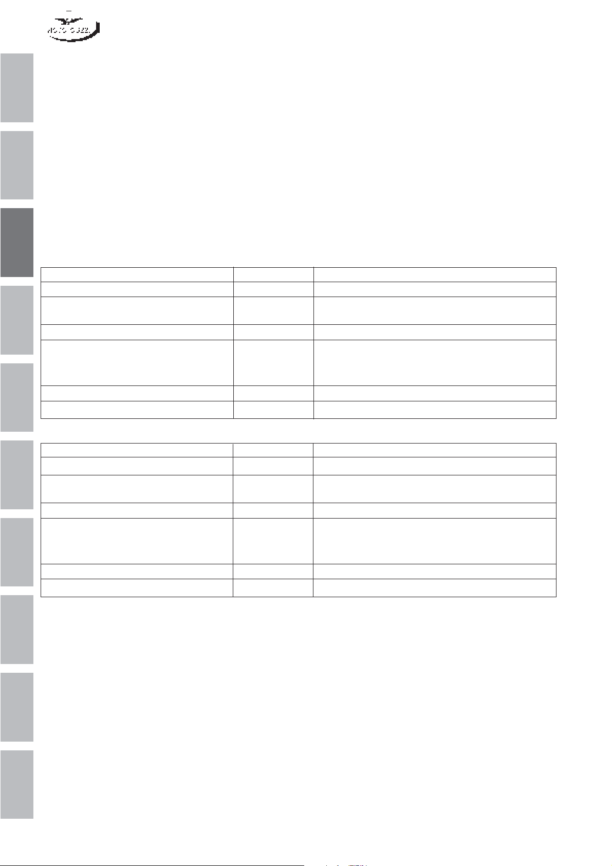
Ogni veicolo è contraddistinto da un numero di identificazione impresso sulla pipa del telaio e sul basamento
motore.
Il numero impresso sulla pipa del telaio è riportato sul
libretto di circolazione e serve agli effetti di legge per
l'identificazione del motociclo stesso; questo numero è
composto da cifre e lettere come nell’esempio sotto riportato.
MARCATURA DEL TELAIO
✩ZGULK01001M111111✩
Legenda:
ZGU: codice WMI (World manufacture identifier);
LK: tipo di veicolo;
0100: variante versione normale (0101 CATALIZZA-
TA);
1: anno di fabbricazione variabile (1 per 2001 - 2
per 2002);
M: stabilimento di produzione;
111111: numero progressivo.
Each vehicle is marked by an identification number
stamped on the chassis lug and on the engine crankcase.
The number marked on the chassis lug and reported in
the registration document is the legal identification of the
motorbike; this number is composed of digits and letters,
as in the example illustrated below.
FRAME MARKING
✩ZGULK01001M111111✩
Key:
ZGU: WMI (World manufacture identifier) code;
LK: motorcycle type;
0100: variant of normal version (0101 CATALYTIC
CONVERTER);
1: Year of production (1 for 2001 - 2 for 2002);
M: production plant;
111111: sequential number
1
2
3
4
5
6
7
8
Fig. 02-01 Fig. 02-02
CARATTERISTICHE GENERALI GENERAL FEATURES
9
10
5

1
2
3
4
5
6
7
8
9
10
6

LUBRIFICANTI E RIFORNIMENTI
LUBRICANTS AND SUPPLIES
1
2
3
4
5
6
7
8
9
10
1
1 OLIO MOTORE
1 ENGINE OIL
Un buon olio motore ha delle particolari qualità.
Fate uso solamente di olio motore altamente detergen-
1
te, certificato sul contenitore come corrispondente, o superiore, alle necessità di servizio SE, SF o SG.
2
2 TABELLA RIFORNIMENTI
3
Parti da rifornire Litri Prodotti da impiegare
Serbatoio carburante (riserva 4 lt circa) 14 Benzina senza piombo (95 NO-RM/min.)
Coppa motore 2 Olio "Agip SUPER 4T SAE 15W/50"
4
Scatola cambio 1,000 Olio "Agip Rotra MP SAE 80 W/90"
Scatola trasmissione posteriore 0,170 di cui:
5
Forcella telescopica (per gamba) 0,400 Olio per ammortizzatori "SAE 10"
Impianto frenante anteriore e posteriore — Fluido "Agip Brake Fluid - DOT4"
Good engine oils offer special features. Only use oils
with high detergent power, certified as equivalent or
superior to SE, SF or SG duty (this is marked on the
container).
2 LIQUID SUPPLIES CHART
Olio "Agip RACING 4T SAE 5W/40"
0,160 Olio "Agip Rotra MP SAE 85 W/140"
0,010 Olio "Agip Rocol ASO/R" oppure "Molykote tipo A"
6
7
8
9
Description Quantity Recommended products
Fuel tank (reserve approx 4 lt) 14 Unleaded petrol (95 NO-RM/min.)
Oil sump 2 "Agip SUPER 4T SAE 15W/50" oil
"Agip RACING 4T SAE 5W/40 oil
Gear box 1.000 “Agip Rotra MP SAE 80 W/90” oil
Rear drive box (bevel set lub) 0.170 of which:
0.160 “Agip Rotra MP SAE 85 W/140” oil
0.010 “Agip Rocol ASO/R” oil or “Molykote type A” oil
Front fork (each leg) 0.400 Shock-Absorber oil "SAE 10"
Braking circuits (front and rear) — "Agip Brake Fluid - DOT4" fluid
10
2
LUBRIFICANTI E RIFORNIMENTI
LUBRICANTS AND SUPPLIES

PROGRAMMA DI MANUTENZIONE
MAINTENANCE PROGRAMME
1
2
3
4
5
6
7
8
9
10
1
1
2
3
4
sibili; ai 500 km controllare il livello
5
6
7
8
1500 Km 5000 Km 10000 Km 15000 Km 20000 Km 25000 Km 30000 Km 35000 Km 40000 Km 45000 Km 50000 Km
9
10
PERCORRENZE
OPERAZIONI
Olio motore RRR RR R R RRRR
Filtro olio a cartuccia RRR RR R R RRRR
Filtro olio a rete CC C
Filtro aria RR RR R R RRRR
Candele RR RR R R RRRR
Giuoco valvole AAA AA A A AAAA
Carburazione AAA AA A A AAAA
Serraggio bulloneria AAA AA A A AAAA
Tubazioni CC C C C C
1 PROGRAMMA DI MANUTENZIONE
2
PROGRAMMA DI MANUTENZIONE
Olio cambio RAR AR A R ARAR
Olio trasmissione posteriore RAR AR A R ARAR
Cuscinetti ruote e sterzo AA
Olio forcella anteriore RR R
Motorino avviamento e generatore AA
Fluido impianto frenante AAA AR A A ARAA
Pastiglie freni AAA AA A A AAAA
Serraggio dadi teste cilindro A
dell'olio motore.
A = Manutenzione - Controllo - Regolazione - Eventuale sostituzione. / C = Pulizia. / R = Sostituzione.
Saltuariamente controllare il livello dell'elettrolito nella batteria e lubrificare le articolazioni dei comandi ed i cavi fles
In ogni caso sostituire l'olio motore, il filtro olio ed il fluido frenante almeno una volta all'anno.
Controllare periodicamente la tensione dei raggi.
MAINTENANCE PROGRAMME
(300 miles) check the engine oil
1
2
3
4
(1500 Km) (5000 Km) (10000 Km) (15000 Km) (20000 Km) (25000 Km) (30000 Km) (35000 Km) (40000 Km) (45000 Km) (50000 Km)
5
6
7
8
MILEAGE COVERED 1000 mi. 3000 mi. 6000 mi. 9000 mi. 12000 mi. 15000 mi. 18000 mi. 21000 mi. 24000 mi. 27000 mi. 30000 mi.
ITEMS
Engine oil RRRRRRRRRRR
Oil filter cartridge RRRRRRRRRRR
1 SERVICE SCHEDULE
Wire gauze oil filter CC C
PROGRAMMA DI MANUTENZIONE
Air filter RRRRRRRRRR
Spark plugs RRRRRRRRRR
Rocker clearance AAAAAAAAAAA
Carburation AAAAAAAAAAA
Nuts and bolts AAAAAAAAAAA
Pipes CC C C C C
Gearbox oil RARARARARAR
Rear drive box oil RARARARARAR
Wheel and steering bearings AA
Front forks oil RR R
Starter motor and generator AA
Brake system fluid AAAARAAARAA
Brake pads AAAAAAAAAAA
Tightening of cylinder head nuts A
9
10
level.
A = Maintenance - Inspection - Adjustment - Possible replacement / C = cleaning / R = Replacement
Occasionally check the electrolyte level in the battery and lubricate the control joints and the flexible cables; every 500 km
In any case, the oil, the oil filter and the braking fluid should be replaced once a year.
Periodically check the tightening of the spokes.
MAINTENANCE PROGRAMME
3

1
2
3
4
5
6
7
8
9
10
4

ATTREZZATURA SPECIFICA
COPPIE DI SERRAGGIO
E
SPECIFIC TOOLS
TIGHTENING TORQUES
AND
1
2
3
4
5
6
7
8
9
10
1
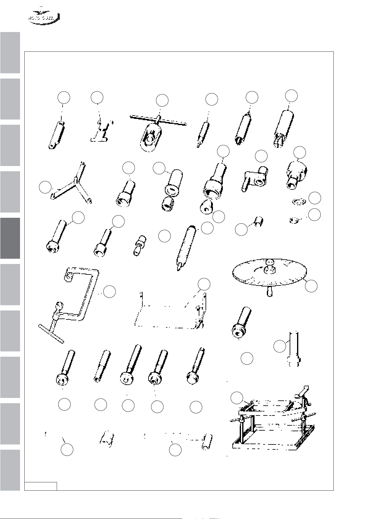
1 ATTREZZATURA SPECIFICA
1
1 SPECIFIC TOOLS
2
3
4
5
10
11
26
22
7
9
13
2
30
8
24
23
29
20
16
1
14
5
12
21
6
7
8
9
6
32
15
27
3
31
19
25
17
4
33
18
28
10
Fig. 05-01
2
ATTREZZATURA SPECIFICA E COPPIE DI SERRAGGIO
SPECIFIC TOOLS AND TIGHTENING TORQUES

Pos. N. Codice Denominazione
Part. number
1 19 92 73 00 Bussola per montaggio anello di tenuta sull’albe-
ro secondario
2 19 92 72 20 Attrezzo per montaggio anello di tenuta sul co-
perchio distribuzione (albero motore)
3 10 90 72 00 Attrezzo per smontaggio e montaggio valvole
4 19 92 61 00 Punzone per anello di tenuta pignone coppia co-
nica
5 19 92 88 00 Attrezzo premontaggio allineamento coppia co-
nica
6 19 92 94 00 Punzone per cuscinetto albero frizione sulla sca-
tola
7 19 92 60 00 Punzone per anello tenuta scatola trasmissione
8 19 90 59 00 Punzone per anello tenuta sull’albero frizione
9 19 92 72 00 Punzone per montaggio anello di tenuta sul co-
perchio scatola cambio per albero secondario
10 19 90 65 00 Attrezzo montaggio e centraddio disco frizione
11 19 91 18 00 Attrezzo tenuta volano
12 19 92 72 02 Distanziale per montaggio anello sull’albero se-
condario
13 19 90 70 00 Estrattore anello interno sul perno forato
14 19 92 75 00 Estrattore anello esterno cuscinetto scatola tra-
smissione
15 19 92 62 00 Punzone per cuscinetto sul pignone coppia coni-
ca
16 19 92 77 00 Attrezzo tenuta ingranaggio rinvio per smontaggio
cambio
17 19 92 63 00 Punzone per cuscinetto albero primario sulla sca-
tola cambio
18 19 92 64 00 Punzone per anello esterno cuscinetto conico sul
corpo porta pignone coppia conica
19 19 92 65 00 Punzone per anello esterno del cuscinetto sca-
tola trasmissione
20 19 92 76 00 Estrattore per cuscinetto porta braccio oscillante
sul coperchio scatola cambio
21 19 92 78 00 Bussola di riduzione per attrezzo smontaggio
valvole (tale attrezzo porta il N. 10 90 72 00)
22 19 92 79 00 Punzone per pressare l’anello interno del cusci-
netto sul perno forato
23 12 91 20 00 Attrezzo montaggio anello di tenuta sull’albero
motore lato volano
24 19 92 71 00 Punzone per pressare l’anello di tenuta sulla
flangia e albero motore lato volano
25 18 91 24 50 Supporto motore (è adattabile montando un qua-
dretto di legno od altro materiale)
26 14 92 69 00 Attrezzo controllo livellatura galleggianti dei car-
buratori
27 19 90 25 00 Supporto scatola cambio
28 19 92 96 00 Disco graduato
29 19 92 60 20 Punzone montaggio cappellotto su guida valvole
30 19 92 73 20 Attrezzo per montaggio anello di tenuta sul co-
perchio distribuzione (albero a camme)
31 19 92 64 60 Introduttore pista esterna cuscinetto albero se-
condario
32 19 90 54 60 Chiave tenuta dado per albero frizione
33 19 90 71 60 Attrezzo di tenuta albero frizione
Designation
Bush for fitting oil seal on secondary shaft
Tool for fitting oil seal on timing cover (crankshaft)
Valves disassembly / assembly tool
Punch for bevel gear pair pinion oil seal
Bevel gear pair alignment preassembly tool
Punch for clutch shaft bearing on case
Punch for transmission case oil seal
Punch for clutch shaft oil seal
Punch for assembling oil seal on gearbox cover
for secondary shaft
Clutch disk assembly and centring tool
Flywheel holder tool
Spacer for installation of ring on secondary
shaft
Puller for internal ring on hollow shaft
Puller for transmission case bearing external
ring
Punch for bearing on bevel gear pair pinion
Intermediate gear holding tool for removal of
gearbox
Punch for primary shaft bearing on gearbox
Punch for conical bearing external ring on bevel
gear pair pinion holder body
Punch for transmission case bearing outer ring
Puller for swinging arm holder bearing on gearbox cover
Reducer bush for valve disassembly tool (this
tool is marked with No. 10 90 72 00)
Punch for driving internal bearing ring on hollow
shaft
Tool for assembling oil seal on crankshaft - flywheel side
Punch for driving oil seal on flange and crankshaft – flywheel side
Engine stand (can be adapted by installing a
block made of wood or other material)
Carburettor floats level check tool
Gearbox support
Graduated disk
Punch for mounting cap on valve guide
Tool for assembling oil seal to timing cover
(camshaft)
Secondary shaft bearing outer race inserter tool
Clutch shaft nut holding wrench
Clutch shaft holding tool
1
2
3
4
5
6
7
8
9
10
ATTREZZATURA SPECIFICA E COPPIE DI SERRAGGIO
SPECIFIC TOOLS AND TIGHTENING TORQUES
3

2 COPPIE DI SERRAGGIO
1
2
3
4
5
6
7
8
9
Denominazione Coppia di serraggio
(Nm)
Teste cilindri
Viti di fissaggio coperchi teste motore 10
Fissaggio candele accensione 20÷30
Basamento e coperchi
Dado fissaggio teste-cilindri al basamento (M 10) 40÷42
Dado fissaggio teste-cilindri al basamento (M 10) 28÷30
Dadi unione basamenti (M 8) 22÷25
Dadi unione basamenti (M 10) 38÷40
Viti di fissaggio coperchio distribuzione 10
Viti fissaggio coppa olio 10
Imbiellaggio
Dado autobloccante fissaggio cappelli alle bielle 30÷32
Viti fissaggio volano all’albero motore 40
Viti fissaggio corona dentata 10
Distribuzione
Raccordo fissaggio albero camme al basamento 30
Viti fissaggio ingranaggio sull’albero a camme 25÷27
Avviamento elettrico
Viti di fissaggio motorino avviamento 30
Alimentazione
Viti di fissaggio pipe aspirazione alle teste 10
Lubrificazione
Viti fissaggio pompa olio al basamento 10
Vite fissaggio coperchietto tenuta cartuccia filtrante 25
Accensione
Viti fissaggio statore del generatore 5
Viti fissaggio rotore del generatore 32÷35
Frizione
Dado fissaggio albero frizione 100
Cambio velocità
Dadi bloccaggio albero primario 100
Viti fissaggio coperchio alla scatola cambio 10
Viti fissaggio scatola cambio al coperchio campana frizione 10
Parti collegamento motore
Dado per tirante anteriore 45
Dado per viti lunghe e corte 45
Viti fissaggio coperchio campana frizione al motore 25÷30
Trasmissione posteriore
Dado bloccaggio pignone conico alla custodia 10
Viti fissaggio corona conica al perno forato 42
Viti fissaggio coperchio alla scatola trasmissione 25
Telaio
Viti fissaggio, semi culla, culla telaio 45
Viti fissaggio cavalletto centrale 23
Sospensione anteriore
Viti fissaggio testa della forcella 45
Viti fissaggio base della forcella 45
Viti fissaggio gambale al perno ruota 10
Sospensioni posteriori
Viti fissaggio sospensioni posteriori parte superiore e inferiore 23
Ruota anteriore e disco freno
Perno ruota 80
Viti fissaggio disco freno al mozzo 23
10
4
ATTREZZATURA SPECIFICA E COPPIE DI SERRAGGIO
SPECIFIC TOOLS AND TIGHTENING TORQUES

2 TIGHTENING TORQUES
Designation Tightening torque
(Nm)
Cylinder heads
Cylinder head covers fixing screws 10
Spark plugs 20÷30
Crankcase and covers
Cylinder heads to crankcase fixing nut (M 10) 40÷42
Cylinder heads to crankcase fixing nut (M 10) 28÷30
Crankcases joining nuts (M 8) 22÷25
Crankcases joining nuts (M 10) 38÷40
Timing cover fixing screws 10
Sump fixing screws 10
Connecting rod group
Caps to connecting rods fixing locknut 30÷32
Flywheel to crankshaft fixing screws 40
Ring gear fixing screws 10
Timing
Camshaft to crankcase fixing connection 30
Timing gear to camshaft fixing screws 25÷27
Electric starting
Starter motor fixing screws 30
Fuel supply
Intake manifolds to heads fixing screws 10
Lubrication
Oil pump to crankcase fixing screws 10
Filter cartridge sealing cover fixing screw 25
Ignition
Alternator stator fixing screws 5
Alternator rotor fixing screws 32÷35
Clutch
Clutch shaft fixing nut 100
Gearbox
Primary shaft fixing nuts 100
Cover to gearbox fixing screws 10
Gearbox to clutch housing cover fixing screws 10
Engine connecting parts
Front tie rod nut 45
Nut for long and short screws 45
Clutch housing cover to engine fixing screws 25÷30
Final drive
Bevel pinion to case fixing nut 10
Bevel gear to hollow shaft fixing screws 42
Cover to transmission case fixing screws 25
Frame
Semi-cradle, frame cradle fixing screws 45
Centre stand to frame fixing screws 23
Front suspension
Fork head fixing screws 45
Fork base fixing screws 45
Slider to wheel spindle fixing screws 10
Rear suspension
Rear suspension upper and lower sections fixing screws 23
Front wheel and brake disc
Wheel spindle 80
Brake disc to hub fixing screws 23
1
2
3
4
5
6
7
8
9
10
ATTREZZATURA SPECIFICA E COPPIE DI SERRAGGIO
SPECIFIC TOOLS AND TIGHTENING TORQUES
5

Ruota posteriore e disco freno
Dado fissaggio perno ruota 120
1
Vite sul forcellone oscillante fissagigo perno ruota 45
Viti fissaggio disco freno 23
Sterzo
Vite fissaggio testa di sterzo 50
2
VALORI STANDARD Coppia serraggio
Viti e dadi ø 4 3
Viti e dadi ø 5x0,8 5,5
Viti e dadi ø 6x0,1 10
3
Viti e dadi ø 8x1,25 23
Viti e dadi ø 10x1,5 45
N.B. I valori standard si riferiscono a viti a testa esagonale o a testa cilindrica con esagono incassato. Per viti a testa
cilindrica bassa con esagono incassato o a testa bombata con esagono incassato si dovrà ridurre la coppia di
serraggio in funzione della dimensione minore della cava e della sua altezza.
4
(Nm)
5
6
7
8
9
10
6
ATTREZZATURA SPECIFICA E COPPIE DI SERRAGGIO
SPECIFIC TOOLS AND TIGHTENING TORQUES

Rear wheel and brake disc
Wheel spindle fixing nut 120
Wheel spindle fixing screws on swinging arm 45
Brake disc fixing screws 23
Steering
Steering head securing screw 50
STANDARD VALUES Tightening torque
(Nm)
Screws and nuts ø 4 3
Screws and nuts ø 5x0,8 5.5
Screws and nuts ø 6x0,1 10
Screws and nuts ø 8x1,25 23
Screws and nuts ø 10x1,5 45
N.B. Standard values refer to hexagonal head or cheese-headed Allen screws. For short cheese-headed
Allen or roundheaded Allen screws it will eb necessary to reduce the tightening torque according to the
smaller recess size and depth.
1
2
3
4
5
6
7
8
ATTREZZATURA SPECIFICA E COPPIE DI SERRAGGIO
SPECIFIC TOOLS AND TIGHTENING TORQUES
9
10
7

1
2
3
4
5
6
7
8
9
10
8

DATI DI CONTROLLO
CHECK DATA
1
2
3
4
5
6
7
8
9
10
1

1 SELEZIONATURA DEI CILINDRI E
PISTONI
1
CONTROLLO DEI COMPONENTI
Controllo usura cilindri:
La misurazione del diametro dei cilindri si deve effettuare a tre altezze, ruotando il comparatore di 90°.
Controllare che i cilindri e i pistoni appartengano alla stessa classe di selezione (D, E, F).
2
Tolleranze di montaggio fra pistoni e cilindri: 0,017 ÷ 0,037
mm.
1 CYLINDERS AND PISTONS SELECTION
COMPONENT INSPECTION
Cylinder wear check:
The cylinder diameter must be measured at three heights,
turning the dial gauge through 90°.
Check that the cylinders and pistons belong to the same
selection class (D, E, F).
Pistons to cylinders assembly tolerances: 0.017 ÷ 0.037
mm.
Controllo pistoni:
In sede di revisione procedere alla disincrostazione del
cielo dei pistoni e delle sedi per anelli elastici; controlla-
3
re il gioco esistente fra cilindri e pistoni sul diametro di
selezionatura; se superiore a quello indicato occorre
sostituire i cilindri e i pistoni.
I pistoni di un motore devono essere equilibrati; è ammessa tra loro una differenza di peso di grammi 2.
SELEZIONATURA Ø CILINDRI
4
GRADO / GRADE “D” GRADO / GRADE “E” GRADO / GRADE “F”
80,000 ÷ 80,010 80,010 ÷ 80,020 80,020 ÷ 80,030
SELEZIONATURA Ø DEL PISTONE
5
GRADO / GRADE “D” GRADO / GRADE “E” GRADO / GRADE “F”
79,973 ÷ 79,983 79,983 ÷ 79,993 79,993 ÷ 80,003
6
Ø 80,000 ÷ 80,030
Pistons check:
When overhauling the engine decoke the piston crowns
and the circlip grooves; check the clearance between
cylinders and pistons on the selection diameter; if the
clearance is greater than the specified value, renew
cylinders and pistons.
The pistons in the same engine must be balanced; pistonto-piston weight difference of 2 grams is permissible.
SELECTION OF CYLINDER DIAMETER
PISTON DIAMETER SELECTION
Misura di controllo per selezionatura
Control dimension for selection
7
8
9
10
Fig. 06-01
2
1^ Misurazione
st
1 Measurement
2^ Misurazione
nd
2 Measurement
3^ Misurazione
rd
3 Measurement
DATI DI CONTROLLO
Ø 79,973 ÷ 80,003
18,2
CHECK DATA

2 QUOTE DI CONTROLLO PISTONE -
FASCE - SPINOTTO
ABC DEFG
3,990÷3,975 1,990÷1,978 1,490÷1,478 79,973÷80,003 0,3÷0,5 0,25÷0,50 0,3÷0,5
HLMN P Q
22,006÷22,000 4,04÷4,02 2,04÷2,02 1,54÷1,52 21,998÷21,994 62,985÷63,000
2 PISTON – PISTON RINGS – GUDGEON
PIN CHECKING DIMENSIONS
1
2
3
4
5
6
ØD
G
ØP
E
B
Q
F
ØD
M
C
7
A
8
N
L
Fig. 06-02
DATI DI CONTROLLO
ØH
CHECK DATA
9
10
3

3 VALVOLE
1
DATI DI ACCOPPIAMENTO TRA VALVOLE E GUIDE
2
3 VALVES
VALVES AND VALVE GUIDES ASSEMBLY DATA
ø Interno guida valvole ø Stelo valvole Giuoco di Montaggio
Valve guide inside diameter Valve stem diameter Assembly Clearance
mm mm mm
3
4
5
6
Aspirazione / Intake 5,500÷5,520 5,480÷5,465
Scarico / Exhaust 5,500÷5,520 5,480÷5,465
Ø5,500÷5,520
0,020÷0,055
Ø5,500÷5,520
7
8
9
10
VALVOLA
ASPIRAZIONE
INTAKE
VALVE
Fig. 06-03
46,5
Ø5,48
Ø34,5±0,1
0
-0,015
5
4
0
Ø5,48
-0,015
'
5
1
+
0
˚
Ø30,5±0,1
46,5
'
5
1
+
0
˚
5
4
VALVOLA
SCARICO
EXHAUST
VALVE
4
DATI DI CONTROLLO
CHECK DATA

4 SEDI VALVOLE
4 VALVE SEATS
PARTICOLARE LAVORAZIONE SEDI VALVOLE
I valori della presente tabella rispecchiano le lavorazioni
di produzione.
Non disponendo di attrezzature adeguata, per la battuta
della valvola utilizzare fresa frontale a 90°.
Dopo la fresatura, per avere un buon accoppiamento ed
una tenuta perfetta tra ghiere e funghi delle valvole, occorre passare alla smerigliatura.
A ø B (Teorico) ø C (Teorico) D
Aspirazione / Intake 32,0 ÷ 32,25 34 1,42 1
Scarico / Exhaust 27,72 ÷ 27,97 30 1,6 1,14
SPECIAL VALVE SEAT MACHINING
The values in the table reflect the production machining
values.
If you do not dispose of suitable tools, use a 90° end hob
for the valve seat.
After machining, for proper assembly and perfect sealing
between valve seats and heads, the seats must be
ground.
B (Theoretical) ø C (Theoretical)
1
2
3
4
- ASPIRAZIONE
- INTAKE
Fig. 06-04
- SCARICO
- EXHAUST
5
6
7
8
Fig. 06-05
DATI DI CONTROLLO
CHECK DATA
9
10
5

5 MOLLE VALVOLE
5 VALVE SPRINGS
1
La molla è del tipo a passo variabile; in caso di montaggio fare attenzione a posizionare la molla sul piattello
inferiore in modo che le spire a passo ravvicinato siano
rivolte verso la testa del motore come indicato dalla freccia (fig. 06-06).
2
3
4
The spring is a variable pitch type; when assembling
ensure the spring is placed on the lower washer in such
a way that the tighter coils are facing the cylinder head,
as shown by the arrow (fig. 06-06).
5
6
7
8
Fig. 06-07
FREE SPRING
ø inside
9
10
Fig. 06-06
6
DATI DI CONTROLLO
ø average
CHECK DATA

6 SISTEMA DI DISTRIBUZIONE
6 TIMING SYSTEM
DIAMETRO DEI SUPPORTI DELL’ALBERO DELLA DISTRI-
BUZIONE E RELATIVE SEDI SUL BASAMENTO SUPERIORE
ø supporto albero ø sedi sul basamento giuoco di montaggio
shaft support ø crankcase seats ø assembly clearance
mm mm mm
Lato distribuzione / Timing end 33,950÷33,975 34,025÷34,050 0,050÷0,100
Lato volano / Flywheel end 29,987÷30,000 30,020÷30,041 0,020÷0,054
DATI DI ACCOPPIAMENTO DELLE PUNTERIE CON LE SEDI
SUL BASAMENTO
DATI DI ACCOPPIAMENTO FRA BILANCIERI E PERNI
(PRODUZIONE)
ø interno dei bilancieri ø perno porta bilancieri ø giuoco di montaggio
rocker arms inside ø rocker arm pivot pin ø assembly clearance ø
(PRODUZIONE)
ø sedi ø esterno punterie ø giuoco di montaggio
seats ø tappets outside ø assembly clearance ø
mm mm mm
14,006÷14,017 13,982÷14,000 0,006÷0,035
mm mm mm
DIAMETER OF THE CAMSHAFT SUPPORTS AND RELATIVE
SEATS ON THE UPPER CRANKCASE
ASSEMBLY DATA OF TAPPETS WITH SEATS IN CRANKCASE
(PRODUCTION)
ROCKER ARMS-PINS ASSEMBLY DATA (PRODUCTION)
1
2
3
4
5
18,032÷18,059 17,983÷17,994 0,034÷0,076
Ball ø 10
Control dimension (on ball centres)
6
7
8
9
Fig. 06-08
DATI DI CONTROLLO
Exhaust
Exhaust
Intake
Intake
CHECK DATA
10
7

7 BIELLE
1
Revisionando le bielle effettuare i seguenti controlli:
- Condizioni delle boccole e gioco tra le stesse e gli
spinotti;
- Parallelismo degli assi;
- Cuscinetti di biella.
I cuscinetti sono del tipo a guscio sottile, con lega
2
antifrizione che non consente alcun adattamento; se
si riscontrano tracce di ingranamento o consumo occorre senz’altro sostituirli.
- Gioco tra albero motore e cuscinetto di biella a 90° dai
piani di giunzione: min. 0,020, max. 0,061.
3
7 CONNECTING RODS
When overhauling the connecting rods perform the
following checks:
- Condition of bushes and clearance between bushes
and gudgeon pins;
- Parallelism of axes;
- Connecting rod bearings.
The bearings are of the thin shell type, with anti-friction
alloy that does not allow any bedding in; if traces of
seizure or wear are noted the bearings must be
renewed immediately.
- Clearance between crankshaft and connecting rod
bearing at 90° from the mating planes: min. 0.020,
max. 0.061.
CONTROLLO PARALLELISMO DEGLI ASSI
Prima di montare le bielle occorre verificarne la
quadratura. Occorre cioé controllare che i fori testa e
piede di biella siano paralleli e complanari.
L’errore massimo di parallelismo e complanarità dei due
4
assi della testa e piede biella misurati alla distanza di
200 mm deve essere di ±0,10 mm .
PESO
Il peso della biella completa di viti e boccola superiore,
5
ma senza semicuscinetti è di 428 ÷ 432 gr.
6
7
AXES PARALLELISM CHECK
Before assembling the connecting rods check
squareness. This means checking that the big and small
end bores are perfectly parallel and co-planar.
The maximum parallelism and co-planarity error of the
two axes of the connecting rod big and small ends
measured at a distance of 200 mm must be ±0.10 mm.
WEIGHT
The weight of the connecting rod complete with screws
and upper bushing but without half-shells is 428 ÷ 432.
A
Settore entro il quale deve trovarsi
il taglio della bussola
Sector within which the bushing
opening must lie
15˚
15˚
Zone di asportazione materiale per
ottenere uguaglianza di peso tra
bielle e corretta ripartizione delle
masse per l’equilibratura.
A
Material removal area to obtain
identical weight between connecting
rods and correct distribution of
mass for balancing purposes.
8
9
10
Fig. 06-09
8
DATI DI CONTROLLO
A
Coppia di serraggio 30÷32 Nm
Tightening torque 30÷32 Nm
N.B. Curare scrupolosamente il parallelismo
degli assi X-X/Y-Y = 0,100 su 200 mm
N.B. Pay the utmost attention to ensuring
perfect parallelism of axes X-X/Y-Y = 0.100 over
200 mm
CHECK DATA

8 ALBERO MOTORE
8 CRANKSHAFT
CONTROLLO
N.B. L’albero motore essendo nitrurato non è
rettificabile; pertanto qualora si verificasse
un’usura, un’ovalizzazione o rigatura profonda
occorre sostituire l’albero motore.
RIMONTAGGIO
Gioco di montaggio tra i rasamenti delle bielle e spalle
dell’albero motore 0,265 ÷ 0,515 mm.
EQUILIRATURA
Per equilibrare staticamente l’albero motore applicare sul
bottone di manovella un peso di 1,224 kg.
INSPECTION
N.B. As the crankshaft is nitrided it cannot be
ground; therefore, when it displays wear, out of
round, or deep scoring, it must be renewed.
REASSEMBLY
Assembly clearance between connecting rod shims and
crankshaft: 0.265 ÷ 0.515 mm.
BALANCING
For static balancing of the crankshaft apply a weight of
1.224 kg on the crankpin.
1
2
3
4
ø18 f8
ø27,8
+0
-0,1
ø28 h8
0
-0,033
5
6
7
8
Fig. 06-10
DATI DI CONTROLLO
CHECK DATA
9
10
9

9 POMPA OLIO
9 OIL PUMP
CONTROLLO
1
Per le misure vedere disegno fig. 06-11.
GIOCHI DI MONTAGGIO
- tra corpo pompa e rotore esterno
0,080 ÷ 0,135 mm;
- tra foro sul rotore interno e albero comando pompa
2
3
0,016 ÷ 0,061 mm;
- tra foro sul corpo pompa e albero comando pompa
0,016 ÷ 0,061 mm.
TARATURA
I valori di taratura della pressione olio sono:
4 ÷ 4,2 kg/cm
2.
4
INSPECTION
For measurements refer to fig. 06-11.
ASSEMBLY CLEARANCES
- between pump body and external rotor
0.080 ÷ 0.135 mm;
- between bore on internal rotor and pump drive shaft
0.016 ÷ 0.061 mm;
- between bore on pump body and pump drive shaft
0.016 ÷ 0.061 mm.
CALIBRATION
Oil pressure calibration values are as follows:
4 ÷ 4.2 kg/cm
2.
5
6
7
8
DEVIATION 0.03 mm
AXIAL ERROR 0.03 mm
ASSEMBLY BLIND HOLE
ASSEMBLY BLIND HOLE
AXIAL ERROR 0.03 mm
AXIAL ERROR 0.02 mm
DEVIATION 0.03 mm
9
10
Fig. 06-11
10
DATI DI CONTROLLO
BLIND HOLE FOR ASSEMBLY PHASE
SHOWS LARGER BASE RESULTING FROM
FORGING DRAFT
CHECK DATA

OPERAZIONI DI CONTROLLO E MANUTENZIONE
INSPECTION AND MAINTENANCE OPERATIONS
1
2
3
4
5
6
7
8
9
10
1

1 FRIZIONE
1
2
3
4
1 CLUTCH
Punto di Vernice per Identificazione
Identification paint spot
5
Fig. 07-00
FRIZIONE “AP” - Meccanismo frizione
Carico d’innesto 180÷200 Kg - Identificazione: punto di
vernice giallo.
6
CONTROLLO
Verificare che il disco non sia rigato o molto usurato; il
disco nuovo ha uno spessore di 7,0 mm, se ridotto a 5,8
mm sostituire il disco.
7
8
“AP” CLUTCH – Clutch mechanism
Engagement force 180÷200 kg – Identification : spot of
yellow paint.
INSPECTION
Check that the disk is not scored or heavily worn; a new
clutch disk is 7.0 mm thick. If the clutch disk is 5.8 mm
thick or less it must be renewed.
9
10
Fig. 07-01
2
OPERAZIONI DI CONTROLLO E MANUTENZIONE INSPECTION AND MAINTENANCE OPERATIONS

2 POMPA OLIO
2 OIL PUMP
CONTROLLO
Elemento (Vedi fig. 07-02)
Element (See fig. 07-02)
Corpo pompa olio “4”
Oil pump body “4”
Rotore esterno “6”
External rotor “6”
Rotore interno “5”
Internal rotor “5”
INSPECTION
Verifica
Check
Verificare che i piani e le sedi interne del corpo pompa olio non siano rigati, rovinati o
ammaccati.
Check that the faces and internal seats of the pump body are not scored, damaged or
dented.
Verificare che le superfici interne ed esterne ed i piani non siano rigati o ammaccati,
altrimenti sostituire entrambi i rotori.
Check that the internal and external surfaces and the faces are not scored or dented,
otherwise renew both rotors.
Verificare che le superfici interne ed esterne ed i piani non siano rigati o ammaccati,
altrimenti sostituire entrambi i rotori.
Check that the internal and external surfaces and the faces are not scored or dented,
otherwise renew both rotors.
1
2
3
4
Cuscinetti a rullini “3”
Roller bearings “3”
Albero comando pompa olio “2”
Oil pump drive shaft “2”
Per le misure di controllo vedi Sez. 6 Cap. 9.
5
4
3
Verificare che i rullini dei suddetti cuscinetti non siano rovinati, altrimenti sostituire i cuscinetti.
Check that the rollers of the foregoing bearings are not damaged, otherwise renew the
bearings.
Verificare che non sia rovinato e che la filettature sia integra, che la cava per chiavella
non sia slabrata e che la testa che lavora nel rotore interno non sia rovinata, altrimenti
sostituire l’albero.
Check that the drive shaft is not damaged and that the threads are in good condition, that
the keyway is not burred and that the end that operates in the internal rotor is not damaged,
otherwise renew the shaft.
6
2
5
6
7
For the control dimensions refer to Section 6
Chap. 9.
8
9
Fig. 07-02
OPERAZIONI DI CONTROLLO E MANUTENZIONE INSPECTION AND MAINTENANCE OPERATIONS
10
3

3 VALVOLA REGOLAZIONE PRESSIONE
OLIO
1
CONTROLLI
- Verificare che il pistone “A” sia levigatissimo e scorra
liberamente nella sua sede sul basamento altrimenti
sostituirlo;
- che la filettatura del tappo “B” sia in perfetto stato;
- controllare che la molla “C” (fig. 07-04) compressa a
2
26 mm dia un carico di Kg 3,866 ± 5%.
3 OIL PRESSURE CONTROL VALVE
CHECKS
- Check that piston “A” is perfectly smooth and is free to
move in its seat in the crankcase; otherwise, renew
the piston;
- check that the thread of plug “B” is in perfect condition;
- check that spring “C” (fig. 07-04) generates a load of
3.866 kg ± 5% when compressed to 26 mm.
TARATURA
Per variare la taratura della valvola aggiungere o togliere le rondelle “D-E” indicate dalle frecce (fig. 07-03).
I valori di taratura della pressione olio sono:
3
3,2 ÷ 3,8 kg/cm
2
.
4
5
6
CALIBRATION
To adjust valve calibration values add or remove washers
“D-E” shown by the arrows (fig. 07-03).
Oil pressure calibration values are as follows:
3.2 ÷ 3.8 kg/sq.cm
7
8
9
10
A
C
E
B
D
Fig. 07-03 Fig. 07-04
inside ø
C
Under load
Free
4
OPERAZIONI DI CONTROLLO E MANUTENZIONE INSPECTION AND MAINTENANCE OPERATIONS

4 CARBURATORI
4 CARBURETTORS
1
10
37
38
9
36
11
12
16
13
14
15
2
35
17
32
31
33
5
20
8
40
6
29
7
3
29
28
26
27
30
10
9
21
22
23
24
25
2
3
4
5
1
Fig. 07-05
TIPO
N. 2 Carburatori dell’Orto:
- PHBH 30 BD (destro)
- PHBH 30 BS (sinistro).
Diffusore ø mm 30.
41
4
18
TYPE
No. 2 dell’Orto:
- PHBH carburettors 30 BD (right)
- PHBH 30 BS (left).
30 mm ø choke.
6
7
8
9
OPERAZIONI DI CONTROLLO E MANUTENZIONE INSPECTION AND MAINTENANCE OPERATIONS
10
5

PARTICOLARE/ DESCRIZIONE DESCRIPTION DATI REGOLAZIONE CARBURAZIONE/
PART CARBURETTOR BALANCING DATA
1
2
3
4
5
6
7
8
1 Valvola gas Throttle valve 50
2 Spillo conico Taper needle x 88 - 4a tacca/4rd notch
3 Polverizzatore Fuel nozzle 264 T1
4 Getto massimo Main jet 105
5 Getto minimo Slow running jet 32
6 Getto avviamento Starting jet 60
7 Valvola a spillo Needle valve
8 Galleggiante Float g. 9,5
9 Cappuccio cavo gas e avviamento Cap
10 Vite tendifilo Screw
11 Vite Screw
12 Coperchio camera miscela Cover
13 Molla richiamo valvola gas Spring
14 Piastrina rit. fermaglio spillo conico Plate
15 Fermaglio spillo conico Fastener clip
16 Guarnizione coperchio camera misc. Gasket
17 Tubo sfiato Breather pipe
18 Tappo fissaggio vaschetta con OR Chamber plug with O-Ring
19 Gruppo guarnizioni carburatore Gasket set
20 Perno galleggiante Pin
21 Vite fissaggio dispositivo avviam. Screw
22 Coperchio dispositivo avviamento Starter device cover
23 Guarnizione Gasket
24 Molla valvola avviamento Spring
25 Valvola avviamento Starter valve
26 Vite regolazione miscela minimo Screw
27 Molla vite regolazione miscela min. Spring Apertura 1 giro e mezzo circa/
open 1 and 1/2 turns approx.
28 Rondella piana Washer
29 Guarnizione vite reg. miscela min. Gasket
30 Vite regolazione valvola gas Screw
31 Molla vite regol. valvola gas Spring
32 Rondella piana Washer
33 Guarnizione vite reg. valvola gas Gasket
34 Guarnizione getto avviamento Gasket
35 Filtro benzina Fuel filter
36 Pipetta raccordo tubo benzina Union
37 Guarnizione vite fissaggio pipetta Gasket
38 Vite fissaggio pipetta Screw
39 Guarnizione valvola spillo Gasket
40 Guarnizione vaschetta Gasket
41 Vaschetta Chamber
9
10
6
OPERAZIONI DI CONTROLLO E MANUTENZIONE INSPECTION AND MAINTENANCE OPERATIONS

CONTROLLO
Controllare che le sedi e lo spillo conico non siano consumati, che la valvola gas non sia rovinata, che il galleggiante non sia forato, e che gli anelli e guarnizione di
tenuta siano in ottimo stato altrimenti sostituirli. Per quanto riguarda i fori dei getti si sconsiglia nel modo più assoluto di adoperare fili di acciaio per pulirli perché potrebbero alternare la carburazione; per la suddetta operazione consigliamo di adoperare fili di nylon o di ottone.
INSPECTION
Check that the seats and the taper needle are not worn,
that the throttle valve is not damaged, that the float is not
punctured, and that the seal rings and gaskets are in
perfect condition, otherwise renew them. With regard to
the jet orifices we strongly advise against using steel wire
to clean clogged nozzles because this could have a negative effect on the fuel/air mixing system; for this
operation we recommend the use of nylon filaments or
brass wire.
1
2
RIMONTAGGIO
Per le operazioni di rimontaggio invertire l’ordine di montaggio, salvo però che bisogna sostituire le guarnizioni
di carta ed eventualmente gli anelli e guarnizioni di tenuta.
LIVELLATURA GALLEGGIANTE
Accertarsi che il galleggiante sia nel peso stabilito ed
indicato sullo stesso, non presenti alcuna deformazione
e ruoti liberamente sul suo perno.
Tenere il corpo del carburatore nella posizione indicata
in modo che il bilanciere galleggiante sia a leggero contatto con lo spillo e lo stesso spillo con la sede.
In questa condizione controllare che i due
semigalleggianti siano rispetto al piano del corpo alla
quota prescritta: 23,5 ÷ 24,5 mm (fig. 07-06).
Utilizzare l’attrezzo di controllo cod. 14 92 69 00 (vedi
Sez.5 cap.1).
REASSEMBLY
For reassembly procedures invert the order of assembly,
renew all paper gaskets and the seal rings and gaskets
if necessary.
FLOAT LEVELLING
Ensure that the float is of the specified weight as marked
on the part; that it is without any signs of distortion and
that it is free to spin on its pin.
Hold the carburettor body in the position shown so that
the float rocker arm is touching the needle and the needle
is touching its seat.
In this condition check that the two half-floats are at the
prescribed height with respect to the level of the body:
23.5 ÷ 24.5 mm (fig. 07-06).
Use checking tool part number 14 92 69 00 (see Section
5 chap. 2).
3
4
5
6
Fig. 07-06
piano di appoggio
supporting surface
OPERAZIONI DI CONTROLLO E MANUTENZIONE INSPECTION AND MAINTENANCE OPERATIONS
7
8
9
10
7

COMANDI CARBURATORI
- manopola comando gas situata sul lato destro del
1
manubrio;
- levetta comando dispositivo di avviamento a motore
freddo “CHOKE” (“E” di fig. 07-08) situata sul lato
sinistro del manubrio.
2
3
REGOLAZIONE GIOCO CAVI COMANDO “CHOKE”
(FIG. 07-07 E 07-08)
Per regolare il gioco cavi comando “CHOKE” operare
come segue:
- togliere le paratie laterali cromate montate sotto al ser-
4
5
batoio;
- controllare che con la levetta comando “CHOKE” in
posizione di marcia “2”, tra i capicorda delle guaine
delle trasmissioni di comando e le viti tendifilo “D” vi
sia un gioco di mm 3 circa; altrimenti allentare i
controdadi “C” e avvitare o svitare le viti “D”. A fine
operazione bloccare i dadi “C”.
CARBURETOR CONTROLS
- throttle twist grip on right of handlebar;
- “CHOKE” cold start control lever (“E” in fig. 07-07)
located on left side of handlebars.
ADJUSTING THE «CHOKE» CABLE PLAY
(FIG. 07-07 AND 07-08)
To adjust CHOKE cables play, proceed as follows:
- remove the side chrome panels from beneath the fuel
tank;
- With CHOKE control lever in position “2”, check that
there is approx. 3 mm play between the cable sheath
ends and adjuster screws “D”; otherwise, loosen
locknuts “C” and turn cable adjuster screws “D” in the
direction required. After making the adjustment, tighten
locknuts “C”.
6
7
8
9
B
D
C
A
10
Fig. 07-07 Fig. 07-08
8
OPERAZIONI DI CONTROLLO E MANUTENZIONE INSPECTION AND MAINTENANCE OPERATIONS

REGOLAZIONE DELLA CARBURAZIONE, EREGIMEMINI-
MO (FIG. 07-09)
REGOLAZIONE DELLA CARBURAZIONE A MEZZO «VUOTOMETRO»
Per la suddetta regolazione operare come segue:
1- Porre il motociclo sul cavalletto centrale
2- Svitare e togliere le viti con rondelle chiusura fori sulle
pipe aspirazione “F”.
3- Avvitare sui fori delle pipe aspirazione i raccordi sul-
le tubazioni “G” collegate al vuotometro.
4- Avvitare a fondo le viti “M” e successivamente svi-
tarle di 1 giro e 1/2 su entrambi i carburatori; controllare che i due cavi all’imbocco delle viti tendifilo “B”
abbiano una corsa a vuoto di mm 1÷1,5; controllare
pure che i due capicorda sulle guaine delle trasmissioni di comando starter all’imbocco delle viti tendifilo
“D” in posizione di marcia “2” (fig. 07-08) abbiano
una corsa a vuoto di circa 3 mm.
5- Con motore al minimo, alla temperatura di esercizio,
agire sulle viti “A” sino ad ottenere la medesima altezza delle due colonne di mercurio “I” sul quadro
del vuotometro “L”.
6- Ritoccare la posizione delle viti di regolazione mini-
mo benzina “M” fino ad ottenere il minimo di giri più
alto possibile, indi ricontrollare la posizione delle due
colonne di mercurio “I” sul quadro di controllo del
vuotometro “L” ed eventualmente ripetere l’operazione al punto “5”.
7- Regolato il minimo (1200÷1300 giri/min), passare alla
sincronizzazione dei carburatori operando come segue:
- avviare il motore ed accelerare gradualmente
controllando che le due colonne di mercurio “I”
sul quadro di controllo del vuotometro siano allineate, altrimenti agire sulle viti tendifilo delle trasmissioni comando gas “B”, fino ad ottenere il
predetto allineamento.
Effettuata questa verifica accertarsi che i due cavi
all’imbocco delle viti tendifilo “B” abbiano sempre un minimo di corsa a vuoto.
8- A controllo avvenuto, svitare i raccordi delle tubazio-
ni “G” del vuotometro dai fori delle pipe di aspirazione e rimontare sugli stessi fori le viti “F” con relative
rondelle.
BALANCING THE CARBURETTORS AND ADJUSTING THE
IDLE SPEED SETTING
BALANCE CARBURETTORS USING A «VACUUM» GAUGE.
For this adjustment proceed as follows:
1- Set the motorcycle on the centre stand
2- Unscrew and remove the screws with washers
responsible for closing the holes on the intake
manifolds “F”.
3- Screw the fittings on hoses “G” connected to the
vacuum gauge to the holes of the intake manifolds.
4- Fully tighten screws “M” and subsequently loosen
them by 1 and 1/2 turns on both carburettors; check
that the two cables at the entry to the adjuster screws
“B” have 1÷1.5 mm free travel; check also that the
two ends on the choke control cable sheaths at the
entry to the adjuster screws “D” in the run position
“2” (fig. 07-08) feature approximately 3 mm free
travel.
5- With the engine idling at operating temperature,
adjust screws “A” until obtaining the same height in
the two columns of mercury “I” on the dial of vacuum
gauge “L”.
6- Readjust the position of the slow running fuel
adjuster screws “M” until obtaining the minimum
possible engine speed and then check the position
of the two columns of mercury “I” on the dial of
vacuum gauge “L” and repeat step “5” above if
necessary.
7- After you have adjusted idle speed (1200÷1300 rpm),
synchronize the two carburettors as follows:
- start the engine and gradually accelerate,
checking that the two columns of mercury “I” on
the vacuum gauge dials are perfectly aligned,
otherwise adjust the throttle control cable
tensioner screws “B” until the columns of
mercury are aligned as described.
Having made this check ensure that the two
cables at the entry to the adjuster screws “B”
have a small amount of free travel.
8- When this check has been performed, unscrew the
fittings of the tubes “G” of the vacuum gauge from
the holes in the intake manifolds and refit the screws
“F” in the holes with the relative washers.
(FIG. 07-09)
1
2
3
4
5
6
7
Fig. 07-09
G
L
I
M
F
OPERAZIONI DI CONTROLLO E MANUTENZIONE INSPECTION AND MAINTENANCE OPERATIONS
8
9
10
9

REGOLAZIONE REGIME MINIMO
- Per regolare il regime minimo a 1200÷1300 giri/min
1
avvitare o svitare della medesima misura entrambe le
viti “A” (Fig. 07-07).
- Aprire e chiudere qualche volta il comando gas per
controllare se il minimo resta stabile.
ADJUSTING IDLE SPEED
- To adjust idle speed to 1200÷1300 rpm, tighten or
loosen, by the same amount, both screws “A” (Fig.
07-07).
- Open and close the throttle control a few times to
ensure that the idle speed remains stable.
N.B.
2
3
4
5
La regolazione va effettuata con il motore a temperatura di esercizio.
REGOLAZIONE GIOCO CAVI COMANDO GAS
(figg. 07-07)
Per regolare il gioco cavi comando gas operare come
segue:
- togliere le paratie laterali cromate montate sotto al serbatoio;
- controllare che, con la manopola comando gas in posizione di riposo, tra i capicorda delle guaine e le viti
tendifilo “B”, di entrambi i carburatori vi sia un giuoco
di 1÷1,5 mm, altrimenti svitare o avvitare la vite tendifilo
“B”.
Una ulteriore regolazione si può ottenere agendo sulla
vite tendifilo “A” di fig. 07-09A.
N.B.
This adjustment must be carried out with the
engine at normal operating temperature.
ADJUSTING THROTTLE CABLES PLAY
(figs. 07-07)
To adjust throttle cable play proceed as follows:
- remove the side chrome panels from beneath the fuel
tank;
- check that with the throttle in its rest position there is
1÷1.5 mm clearance between the sheath ends and
adjuster screws “B” of both carburettors; otherwise
loosen or tighten cable adjuster screw “B”.
An additional adjustment is available by means of cable
adjuster screw “A” as shown in fig. 07-09A.
6
7
8
9
Fig. 07-09A
10
10
A
OPERAZIONI DI CONTROLLO E MANUTENZIONE INSPECTION AND MAINTENANCE OPERATIONS

5 ACCENSIONE ELETTRONICA MAGNETI
MARELLI “DIGIPLEX”
CONTROLLO MESSA IN FASE
Per controllo della fasatura operare come segue:
- Con motore al regime di 800÷1000 giri/min verificare
con pistola stroboscopica, che l’accensione avvenga
8° prima de P.M.S.
- In caso di necessità è possibile ridurre di 2° l’anticipo
ad altri regimi (non al minimo) collegando il cavo “A”
indicato in fig. 07-10 a massa.
- Valore del trasferro tra i 5 denti ricavati sul volano
motore ed il sensore: 0,3÷0,8 mm (vedi fig. 07-11).
5 MAGNETI MARELLI “DIGIPLEX”
ELECTRONIC IGNITION
TIMING CHECK
Proceed as follows to check the timing:
- With the engine running at 800÷1000 rpm, use a strobe
gun to check that ignition occurs at 8° before T.D.C.
- If necessary, you can reduce the timing advance by 2°
at other speeds (not idle speed) by connecting cable
“A” shown in fig. 07-10, to ground.
- Air gap value between the 5 teeth on the flywheel and
the sensor: 0.3÷0.8 mm (see fig. 07-11).
1
2
N.B.
Nel caso il motore non si avvii prontamente
ruotare la chiave del commutatore di accensione in OFF poi di nuovo in ON e ripetere l’avviamento.
N.B.
If the engine fails to start readily, set the ignition
key to OFF and then set it to ON again and repeat
the start procedure.
3
4
5
6
Fig. 07-10
ENGINE CONTROL UNIT
CENTRALINA ELETTRONICA
CONTATTO RIDUZIONE
D'ANTICIPO
TIMING ADVANCE
REDUCTION CONTACT
OPERAZIONI DI CONTROLLO E MANUTENZIONE INSPECTION AND MAINTENANCE OPERATIONS
A
7
8
9
10
11

1
2
3
4
ATTENZIONE
Per non provocare danneggiamenti all’impian-
to di avccensione elettronica, osservare le seguenti precauzioni:
- in caso di smontaggio e rimontaggio della batteria, accertarsi della perfetta efficienza dei
cavi di collegamento;
- non scollegare la batteria con motore in moto;
- accertarsi della perfetta efficienza dei cavi di
collegamento;
- non eseguire saldature ad elettrico sul veicolo;
- non utilizzare dispositivi antifurto od altri
dispositivi elettrici, non interferire assolutamente con l’impianto elettrico dell’accensione.
WARNING
To avoid the risk of damage to the electronic
ignition system observe the following
precautions:
- in the event of removal and refitting of the
battery, ensure the battery leads are in perfect
condition and properly connected;
- never disconnect the battery while the engine
is running;
- check that the connection leads are perfectly
efficient;
- do not carry out electrical welding on the
motorcycle;
- do not use anti-theft systems or other
electrical devices; never tamper with the
electrical ignition circuit.
5
6
7
8
9
10
Fig. 07-11
12
OPERAZIONI DI CONTROLLO E MANUTENZIONE INSPECTION AND MAINTENANCE OPERATIONS

6 CANDELE (FIG. 07-12)
6 SPARK PLUGS (FIG. 07-12)
I tipi di candela da impiegare sono:
- NGK-BR8ES, CHAMPION-RN3C, BOSCH-WR4CC.
Distanza tra gli elettrodi: 0,7 mm.
Nel rimontare le candele, fare attenzione che imboc-
chino perfettamente e che si avvitino facilmente nelle loro sedi; se fossero imboccate male, rovinerebbero
il filetto sulle teste; perciò consigliamo di avvitarle a mano
per qualche giro, e di adoperare poi l’apposita chiave
(data in dotazione) per bloccarle a motore freddo.
Anche se le candele appaiono in ottime condizioni, dopo
5.000 km circa, vanno sostituite.
N.B.
Valori inferiori a 0,7 mm possono compromet-
tere la durata del motore.
IMPORTANTE
Per non provocare irregolarità di funzionamen-
to e inefficienza dell'impianto di accensione è
necessario che gli attacchi cavi candela (pipette
candela) e le candele siano del tipo prescritto
(come montati in origine).
Non eseguire verifiche di corrente alle candele
senza l'interposizione delle pipette candele previste in origine, dato che tale operazione potrebbe danneggiare in modo irreparabile la
centralina elettronica.
Type of plugs to be used:
- NGK-BR8ES, CHAMPION-RN3C, BOSCH-WR4CC.
Electrode gap: 0.7 mm.
When fitting the spark plugs make sure that they are
perfectly started in the thread and that they screw in
easily; if badly inserted, the cylinder head thread will be
stripped; we advise starting off with a few turns by hand,
and then tightening up with the supplied plug wrench,
when the engine is cold.
The plugs should be changed after approximately 5000
km (3000 miles), even if they appear to be in perfect
condition.
N.B.
Values lower than 0.7 mm can have a negative
effect on engine life.
IMPORTANT
To avoid either malfunctioning or inefficiencies
of the ignition system, the spark plug lead
connections (spark plug cap) and the spark
plugs must be of the recommended type (as
original equipment).
Do not perform plug current checks if the
original spark plug caps are not fitted, otherwise
the electronic control unit will be irreparably
damaged.
1
2
3
4
5
6
7
8
9
Fig. 07-12
OPERAZIONI DI CONTROLLO E MANUTENZIONE INSPECTION AND MAINTENANCE OPERATIONS
10
13

7 ALTERNATORE - REGOLATORE
DUCATI
1
ATTENZIONE
L’eventuale inversione dei collegamenti danneg-
gia in modo irreparabile il regolatore.
Accertarsi della perfetta efficienza del collega-
mento a massa del regolatore.
2
7 DUCATI ALTERNATOR – REGULATOR
WARNING
If connections are inverted the regulator will be
irreversibly damaged.
Check that the regulator ground connections are
efficient.
CONTROLLI
Le possibili verifiche da effettuare sull’alternatore e sul
regolatore in caso cessi di ricaricarsi la batteria o che la
tensione non venga più regolata sono:
3
ALTERNATORE
A motore fermo scollegare i due cavi gialli del generatore dal resto dell’impianto ed effettuare con un ohmmetro
i seguenti controlli:
CONTROLLO ISOLAMENTO AVVOLGIMENTI VERSO MASSA
4
Collegare un capo dell’ohmmetro ad uno dei due cavi
gialli e l’altro capo a massa (pacco lamellare).
Lo strumento deve indicare un valore superiore a 10 MΩ.
CONTROLLO CONTINUITÀ AVVOLGIMENTI
5
Collegare l’ohmmetro ai capi dei due cavi gialli.
Lo strumento deve indicare un valore di 0,2÷0,3 Ω.
CONTROLLO TENSIONE D’USCITA
Collegare un voltmetro in alternata portata 200 Volt ai
6
capi dei due cavi gialli.
Mettere in moto il motore e verificare che le tensioni in
uscita siano comprese nei valori riportati nella seguente
tabella:
CHECKS
Possible checks to be carried out on the alternator and
regulator if the battery fails to re-charge or the power
supply is no longer regulated.
ALTERNATOR
With the engine switched off, disconnect the two yellow
alternator cables from the rest of the system and then
carry out the following tests with a ohmmeter:
CHECK WINDING ISOLATION TOWARDS GROUND
Connect one prod of the ohmmeter to one of the two
yellow cables and the other prod to ground (laminar pack).
The instrument must give a reading higher than 10 MΩ.
CHECK WINDING CONTINUITY
Connect the two connecting prods of the ohmmeter to
the two yellow cables.
The instrument must give a reading of 0.2÷0.3 Ω.
CHECK THE VOLTAGE OUTPUT
Connect a 200 Volt ac capacity voltmeter to the two yellow
cables.
Start the engine and check that the voltage output is
included within the values indicated in the following table:
7
8
9
10
Giri/min 1000 3000 6000
rpm
Volt a.c./A.C. volt ≥15 ≥40 ≥80
SCHEMA ELETTRICO CON REGOLATORE DUCATI - WIRING DIAGRAM WITH DUCATI REGULATOR
GENERATORE
GENERATOR
Fig. 07-13
ROSSO/RED
COMMUTATORE
GNITION SWITCH
BATTERIA
BATTERY
12V
GIALLO/YELLOW
GIALLO/YELLOW
12V 3W
BIANCO/WHITE
NERO/BLACK
SEZ. CAVO ≥2,5 mm sq.
CABLE SECTION 2.5 sq. mm.
GIALLO/YELLOW
GIALLO/YELLOW
ROSSO/RED
ROSSO/RED
BIANCO/WHITE
NERO/BLACK
REGOLATORE
REGULATOR
DUCATI
14
OPERAZIONI DI CONTROLLO E MANUTENZIONE INSPECTION AND MAINTENANCE OPERATIONS

1
2
3
4
Fig. 07-14
GRAFICO INTENSITA’ DI CORRENTE / CURRENT INTENSITY DIAGRAM
Ampere d.c. / D.C.amperes
G/min Amp. D.C.
rpm D.C. Amps
1000 9,50
1200 13,00
1500 16,50
2000 20,00
3000 23,50
4000 25,00
6000 26,50
10000 27,50
5
6
7
8
9
Fig. 07-15
Giri x 1000
Revs x 1000
OPERAZIONI DI CONTROLLO E MANUTENZIONE INSPECTION AND MAINTENANCE OPERATIONS
10
15

REGOLATORE DUCATI (FIG. 07-16)
Il regolatore è tarato per mantenere la tensione di batteria a valori compresi fra i 14÷14.6 Volt. La lampada spia
1
(accesa a motore spento, chiave inserita) si spegne quando il generatore inizia a caricare (circa 700 giri).
NB. Il regolatore “Ducati” 1a serie è stato montato in produzione fino al telaio n. LK 111944.
2
DUCATI REGULATOR (FIG. 07-16)
The regulator has been calibrated in order to maintain
battery voltage at a value between 14÷14.6 Volts. The
pilot light (illuminated when the engine is not running,
but the key is inserted) will switch off when the alternator
begins to charge (approx. 700 rpm).
N.B. The “Ducati” 1st series regulator was
installed in production up to frame number LK
111944.
VERIFICHE SUL REGOLATORE
Per il controllo del regolatore non sono sufficienti le normali attrezzature di officina, diamo comunque qui di seguito alcune indicazioni su misure che servono ad individuare un regolatore sicuramente difettoso.
3
IL REGOLATORE È SICURAMENTE DIFETTOSO SE:
Dopo averlo isolato dal resto dell’impianto presenta corto circuito fra massa (custodia alluminio) e uno qualsiasi
dei cavi d’uscita.
4
REGOLATORE SHINDENGEN (FIG. 07-17)
Il regolatore è tarato per mantenere la tensione di batteria a valori compresi fra i 14,2 ÷15,2 Volt.
Questo regolatore non prevede la spia rossa di carica
sul cruscotto.
5
6
NB. Il regolatore “Shindengen” 2a serie è stato
montato in produzione dal telaio n. LK 111945.
Regolatore (1a serie)
"DUCATI"
fino al telaio N. LK111944
R
EGULATOR CHECKS
Normal workshop tools are generally insufficient for
regulator checking, however, listed below are certain
operations that can be carried out in order to detect
regulators that are defective.
THE REGULATOR IS CERTAINLY DEFECTIVE IF:
After having isolated it from the rest of the system short
circuits can be detected between ground (aluminium
casing) and any of the output cables.
SHINDENGEN REGULATOR (FIG. 07-17)
The regulator is calibrated to maintain battery voltage at
14.2÷15.2 Volts.
There is no red charge warning light on the dashboard
associated with this regulator.
N.B. The “Shindengen” 2nd series regulator was
fitted in production from frame no. LK 111945.
Regolatore (2a serie)
"SHINDENGEN"
dal telaio N. LK111945
7
8
9
10
DUCATI regulator
(1st series)
up to frame no. LK 111944
Fig. 07-16
Schema elettrico con regolatore “Shindengen” Wiring diagram with “Shindengen” regulator
GIALLO
YELLOW
GIALLO
YELLOW
GENERATORE
GENERATOR
Fig. 07-18
REGOLATORE
REG / RECT
VERDE
GREEN
SHINDENGEN regulator
(2nd series)
from frame no. LK 111945
ROSSO
RED
BIANCO
WHITE
FUSIBILE
CARICA
ELETTRICA
LOAD
BATTERIA
Fig. 07-17
FUSE
BATT
16
OPERAZIONI DI CONTROLLO E MANUTENZIONE INSPECTION AND MAINTENANCE OPERATIONS

8 MOTORINO AVVIAMENTO (VALEO)
8 STARTER MOTOR (VALEO)
Caratteristiche generali
Tensione 12V
Potenza 1,2Kw
Coppia a vuoto 11 Nm
Coppia a carico 4,5 Nm
Pignone Z=9 mod. 2,5
Rotazione lato pignone Antiorario
Velocità 1750 giri/min.
Corrente a vuoto 600 A
Corrente a carico 230 A
Peso 2,8 Kg
ATTENZIONE
Il motorino di avviamento non deve essere
azionato per oltre 5 secondi; se il motore non si
avvia prontamente, attendere 10 secondi prima
di eseguire il successivo avviamento.
In ogni caso agire sul pulsante di azionamento
(START) solo a motore fermo.
General specifications
Voltage 12V
Power 1.2Kw
No-load torque 11 Nm
Torque under load 4.5 Nm
Pinion Z=9 mod. 2,5
Pinion side rotation Counter-clockwise
Speed 1750 rpm.
No-load current 600 A
Current under load 230 A
Weight 2.8 kg.
WARNING
The starter motor must not be run for more than
5 seconds at a time; if the engine fails to start,
wait for 10 seconds before trying to start it again.
In all cases, only press the START button when
the engine is stopped.
1
2
3
4
Fig. 07-19
5
6
7
8
OPERAZIONI DI CONTROLLO E MANUTENZIONE INSPECTION AND MAINTENANCE OPERATIONS
9
10
17

9 BATTERIA
9 BATTERY
La batteria ha una tensione di 12 V e una capacità di 24
Ah; alla sua carica provvede il generatore.
1
ISTRUZIONI PER L’ATTIVAZIONE DELLE BATTERIE CARICA
SECCA
• Rimuovere i tappi;
• Riempire ciascun elemento della batteria con acido
2
3
solforico densità 1,28 (1,23 per i paesi tropicali) fino
a 15 mm sopra le piastre di separazione;
• Lasciare riposare per almeno 20 minuti;
• Verificare il livello dell’elettrolito, se occorre rinnovare con lo stesso acido portando il livello alla misura
precedentemente indicata (non riempire mai fino al
bordo);
• Rimettere i tappi.
ISTRUZIONI PER LA MANUTENZIONE DELLE BATTERIE
CARICHE CON ACIDO
Le batterie cariche secche attivate dopo carica di
4
riavviamento o ricevute cariche con acido devono essere trattate con le seguenti avvertenze:
• Aggiungere almeno ogni mese ACQUA
DEMINERALIZZATA o DISTILLATA (mai acido) in
modo che a riposo il livello dell’acido sia di 15 mm
sopra i separatori;
• Mantenere puliti e serrati i morsetti e ingrassati con
5
6
7
8
vasellina;
• Mantenere asciutta la parte superiore della batteria
evitando traboccamenti di acido, che riducono l’isolamento o corrodono telai e cassette di contenimento;
• Assicurarsi che l’impianto di carica a bordo non dia
cariche eccessive od insufficienti, tenendo presente
che la densità dell’acido deve mantenersi fra 1,21 e
1,28. Se ciò non avvenisse occorre rivedere l’isolamento e l’efficienza dell’impianto di carica e di avviamento;
• Se la tensione ai poli è inferiore a 12,3 v (densità
elettrolito < 1,21) la batteria deve essere ricaricata;
• Le batterie immagazzinate cariche con acido devono
essere periodicamente ricaricate con intensità pari a
1/10 della capacità, mantenendo il livello corretto o la
densità di 1,28 a 25°C;
• Le batterie devono essere montate sul veicolo, ben
serrate dai congegni di fissaggio mantenendo attivi i
dispositivi antivibranti.
Battery voltage is 12 V with 24 Ah capacity. The battery
is charged by the alternator.
INSTRUCTIONS FOR THE ACTIVATION OF DRY BATTERIES
• Remove the plugs;
• Fill each battery element with sulphuric acid, specific
gravity 1.28 (1.23 for tropical countries) up to 15 mm
above the separation plates;
• Leave to rest at least 20 minutes;
• Check the electrolyte level, if necessary top up with
the same acid bringing the level to the previously
indicated level (never fill up to the rim);
• Refit the plugs.
MAINTENANCE INSTRUCTIONS FOR BATTERIES CHARGED
WITH ACID
Dry batteries activated after being recharged or received
charged with acid must be handled with care, following
these warnings:
• At least every month add DEMINERALISED or
DISTILLED WATER (never acid) so that when at rest
the acid level is 15 mm above the separators;
• Keep the terminals clean and tightened and greased
with Vaseline.
• Keep the battery upper part dry, preventing acid
spillage which otherwise reduces isolation and
corrodes frames and housings.
• Make sure that the charging system does not convey
excessive or insufficient charges, always remembering
that the acid specific gravity must be between 1.21
and 1.28. If this is not the case, check the insulation
and the working order of the ignition and charging
system;
• If the voltage at the poles is lower than 12.3 V
(electrolyte specific gravity < 1.21), the battery must
be recharged;
• Stored batteries filled with acid must be periodically
recharged with intensity at 1/10 of their capacity, by
maintaining the proper level or specific gravity of 1.28
at 25°C;
• Batteries must be installed on the vehicle, firmly
secured by the fixing devices and keeping the vibration
damping pads on.
9
10
N.B.
Per le batterie destinate a funzionare in climi
tropicali (temperatura media maggiore di 33
si consiglia la riduzione della densità dell’acido
a 1,23.
18
OPERAZIONI DI CONTROLLO E MANUTENZIONE INSPECTION AND MAINTENANCE OPERATIONS
°C)
N.B.
For batteries that will be used in tropical
climates (average temperature higher than 33
it is recommended that the electrolyte specific
gravity be reduced to 1.23.
°C)

ISTRUZIONI PER LA CARICA DELLA BATTERIA
• Rimuovere i tappi;
• Ricaricare la batteria solo con corrente continua;
• Collegare il cavo positivo (+) del carica batterie al polo
positivo (+) della batteria e il cavo negativo (-) del
carica batterie al polo negativo (-) della batteria;
• Effettuare la ricarica con una corrente pari a 1/10 della
capacità nominale (Ah) della batteria fino a che la
densità dell’acido si aggira intorno al valore di 1,28;
• Spegnere il carica batterie prima di scollegare la batteria;
• Livellare l’acido, tappare e pulire accuratamente.
BATTERY CHARGE INSTRUCTIONS
• Remove the plugs;
• Charge the battery exclusively with direct current;
• Connect the battery charger positive cable (+) to the
battery positive pole (+) and the battery charger negative cable (-) to the battery negative pole (-);
• Recharge the battery with a voltage of 1/10 of the
battery rated capacity (Ah) until the acid specific gravity
reaches a value of around 1.28;
• Turn off the battery charger before disconnecting the
battery;
• Level the acid, fit the plugs, and clean carefully.
1
2
IMPORTANTE
Non invertire mai il collegamento dei cavi della
batteria.
Collegare e scollegare la batteria con l’interruttore d’accensione in posizione “ ”.
Collegare prima il cavo positivo (+) e poi quello
negativo (-).
Scollegare seguendo l’ordine inverso.
ATTENZIONE
Rimontare la batteria soltanto dopo 5/10 minuti
dal disinserimento dell’apparecchio di carica,
in quanto la batteria, continua a produrre, per
un breve periodo di tempo, del gas.
IMPORTANTE
Uno sfiato piegato o attorcigliato può causare
un innalzamento della pressione nella batteria
e danneggiarla.
ATTENZIONE
La batteria contiene acido solforico (elettrolito).
Evitare il contatto con pelle e occhi in quanto
può provocare gravi ustioni.
In caso di contatto della pelle con l’elettrolito
lavate la parte interessata con acqua abbondante.
In caso di contatto con gli occhi, lavate con acqua corrente per almeno 15 minuti e chiamate
un medico immediatamente.
IMPORTANT
Be sure to connect each battery lead to the
matching terminal.
Set the ignition switch to “ ” before connecting
or disconnecting the battery.
Connect the positive (+) lead first, and then the
negative (-) lead.
Disconnect following the reverse order.
WARNING
Refit the battery only 5/10 minutes after discon-
necting the charging apparatus, since the battery continues to produce gas for a short period of time.
IMPORTANT
A bent or twisted breather tube may increase
battery internal pressure and damage it.
WARNING
The battery contains sulphuric acid (electrolyte).
Avoid contact with skin and eyes since it may
cause serious burns.
If your skin comes into contact with electrolyte,
wash the affected part with abundant water.
In case of contact with your eyes, wash them
with running water for at least 15 minutes and
call a doctor immediately.
3
4
5
6
7
ATTENZIONE
Caricate la batteria in luogo ben ventilato.
Portate sempre occhiali e guanti di protezione
quando operate vicino alla batteria.
Evitare l’inalazione dei gas emessi durante la
ricarica della stessa.
Le batterie producono dei gas esplosivi:
tenete lontano da fonti di calore e dal fuoco.
ATTENZIONE
Tenete la batteria lontano dalla portata dei bam-
bini.
OPERAZIONI DI CONTROLLO E MANUTENZIONE INSPECTION AND MAINTENANCE OPERATIONS
WARNING
Charge the battery in a well-ventilated area.
Always wear safety glasses and gloves when
working near the battery.
Do not inhale the gas produced by the battery
while charging.
Batteries generate explosive gases:
keep them away from heat sources and fire.
WARNING
Keep the battery out of reach of children.
8
9
10
19

RIMOZIONE:
• Togliere la sella, i copriaccumulatori laterali e la para-
1
tia cromata sinistra sottosella;
• Sganciare la cinghia di bloccaggio “C”;
• Scollegare il terminale negativo “A” poi quello positivo “B” svitando i dadi;
• Rimuovere la batteria “D” dalla moto.
REMOVAL:
• Remove the seat, the side battery covers, and the lefthand side chrome panel beneath the seat;
• Release the fastening strap “C”;
• Disconnect the negative terminal “A”, then the positive “B” by unscrewing the nuts;
• Remove the battery “D” from the motorcycle.
2
3
4
N.B. Scollegare sempre per primo il terminale
negativo “A” poi quello positivo “B”.
Scollegare e collegare la batteria con l’interruttore d’accensione in posizione “ ”.
N.B. Il terminale negativo “A” è contraddistinto
dalla colorazione nera, quello positivo “B” dalla colorazione rossa.
RIMONTAGGIO:
• Applicare dello spray protettivo per contatti elettrici
sui morsetti della batteria;
• Inserire la batteria “D” nell’apposita sede sulla moto;
• Collegare il terminale positivo “B” poi il terminale negativo “A”;
• Riagganciare la cinghia “C” di bloccaggio.
• Rimontare i copriaccumulatori laterali, la paratia sinistra cromata e la sella.
5
N.B. Always disconnect the negative terminal
first “A” then the positive one “B”.
Set the ignition switch to “ ” before connecting
or disconnecting the battery.
N.B. The negative terminal “A” is black; the
positive terminal “B” is red.
REASSEMBLY:
• Apply protective spray for electrical contacts to the
battery terminals;
• Fit the battery “D” in its seat on the motorcycle;
• Connect the positive terminal “B” then the negative
one “A”;
• Refit the fastening strap “C”.
• Refit the side battery covers, the chromed lateral panel,
and the seat.
6
7
8
9
C
D
10
Fig. 07-20
20
A
OPERAZIONI DI CONTROLLO E MANUTENZIONE INSPECTION AND MAINTENANCE OPERATIONS
B

10 CONTROLLO/SOSTITUZIONE
PASTIGLIE FRENI
Ogni 3000 Km controllare lo spessore delle pastiglie freni:
• Spessore minimo del materiale d’attrito 1,5 mm.
Se lo spessore minimo del materiale d’attrito é inferiore
al suddetto valore, é necessario cambiare le pastiglie.
Dopo la sostituzione non occorre eseguire lo spurgo degli impianti frenanti, ma è sufficiente azionare le leve di
comando ripetutamente fino a riportare i pistoncini delle
pinze nella posizione normale.
In occasione della sostituzione delle pastiglie, verificare
le condizioni delle tubazioni flessibili; se danneggiate
devono essere immediatamente sostituite.
N.B.
In caso di sostituzione delle pastiglie é opportuno, per i primi 100 Km, agire sui freni con moderazione, al fine di permettere un corretto assestamento delle stesse.
La moto è equipaggiata con pinze che permettono la
sostituzione delle pastiglie senza essere rimosse dai rispettivi supporti.
10 BRAKE PAD CHECK/REPLACEMENT
Check the thickness of the brake pads every 3000 km
(2000 miles):
• The minimum thickness of friction material is 1.5 mm.
If the minimum thickness of the friction material is less
than this value, the pads must be renewed.
After replacement, it is not necessary to bleed the braking
system, simply operate the brake levers repeatedly until
the calliper pistons assume their normal position.
When replacing the pads, check the condition of the
flexible brake lines; they must be replaced immediately
if damaged.
N.B.
After the pads have been replaced, use the
brakes with moderation for the first 100 km (60
miles) in order to allow them to bed-in correctly.
The motorcycle is equipped with callipers that allow the
pads to be replaced without removing them from their
respective supports.
1
2
3
4
5
6
7
8
OPERAZIONI DI CONTROLLO E MANUTENZIONE INSPECTION AND MAINTENANCE OPERATIONS
9
10
21

PINZA FRENO ANTERIORE
FRONT BRAKE CALLIPER
SMONTAGGIO:
1
• Rimuovere le 2 coppiglie elastiche “A”;
• Sfilare i 2 perni “B”;
• Rimuovere la molla esterna “C”;
• Rimuovere le 2 pastiglie “D”, se le pastiglie risultassero usurate oltre il limite prestabilito occorrerà sosti-
2
3
tuirle con pastiglie nuove;
RIMONTAGGIO:
• Inserire le 2 pastiglie nella pinza;
• Posizionare la molla esterna nella sua posizione;
• Inserire i perni nelle apposite sedi su pinze, pastiglie
e protezione esterna;
• Inserire le coppiglie elastiche nei perni.
4
DISASSEMBLY:
• Remove the 2 spring cotters “A”;
• Remove the 2 pins “B”;
• Remove the external shield “C”;
• Remove the 2 pads “D”, if the pads are worn beyond
the prescribed limit they must be replaced with new
ones;
REASSEMBLY:
• Fit the 2 pads into the calliper;
• Refit the external shield in its location;
• Insert the pins, pads and external protection into their
seats on the callipers;
• Insert the spring cotters into the pins.
5
6
7
8
A
Fig. 07-21
D
B
C
9
10
Fig. 07-22 Fig. 07-23
22
OPERAZIONI DI CONTROLLO E MANUTENZIONE INSPECTION AND MAINTENANCE OPERATIONS

PINZA FRENO POSTERIORE
REAR BRAKE CALLIPER
SMONTAGGIO:
• Rimuovere l’anello di fermo “A”;
• Sfilare il perno “B”, la molla “C” per liberare cosí le
pastiglie “D”;
• Se quest’ultime risultassero usurate oltre il limite
prestabilito, sostituirle.
RIMONTAGGIO:
• Inserire le 2 pastiglie nella pinza;
• Inserire la molla, il perno e bloccare quest’ultimo con
l’anello di fermo.
DISASSEMBLY:
• Remove the retaining ring “A”;
• Extract pin “B” and spring “C” thus freeing pads “D”;
• If the pads are worn beyond the prescribed limit, renew
them.
REASSEMBLY:
• Fit the 2 pads into the calliper;
• Fit the spring and the pin and secure the pin with the
retaining ring.
1
2
3
4
5
6
C
D
7
A
8
B
Fig. 07-24
OPERAZIONI DI CONTROLLO E MANUTENZIONE INSPECTION AND MAINTENANCE OPERATIONS
9
10
23

11 REGOLAZIONE TENSIONE RAGGI
RUOTA
1
2
3
4
5
Avvertenza per ruote a raggi
Controllare dopo i primi 1500 km e successiva-
mente ogni 5000 km l’integrità e la tensione dei
raggi ruota.
La marcia in condizione di tensione raggi non
corretta o in presenza di uno o più raggi rotti,
può danneggiare la ruota con conseguenti rischi riguardanti la sicurezza e la stabilità del
veicolo.
Rispettare in ogni caso le prescrizioni di carico
massimo consentito.
• Rimuovere la ruota come descritto nei cap. 8-9 sez.
10;
• Rimuovere il pneumatico, la camera d’aria e il
paranippli;
• Individuare i raggi ruota “1” da tendere;
• Operare sul nipplo “2” per regolare la tensione del
raggio “1” interessato;
- avvitare per tendere il raggio;
- svitare per allentare il raggio;
• La coppia di serraggio indicativa dei nippli è:
- ruota anteriore 3 Nm;
- ruota posteriore 4 Nm.
• Ripetere l’operazione per tutti i raggi procedendo in
ordine di successione;
• Dopo aver regolato la tensione dei raggi ruota, procedere alla verifica del gioco assiale e radiale del cerchio ruota.
11 ADJUSTING WHEEL SPOKE TENSION
Important notes regarding spoked wheels
After the first 1500 km (1000 miles) and
thereafter every 5000 km (3000 miles), check the
condition and tension of the wheel spokes.
Riding the motorcycle with incorrect spoke
tension or with one or more broken spokes can
result in damage to the wheel with consequent
grave risks for safety and the stability of the
bike.
Always observe the maximum permissible
loading prescriptions.
• Remove the wheel as described in chaps. 8-9 section
10;
• Remove the tyre, the inner tube, and the nipples guard;
• Identify the wheel spokes “1” that require tensioning;
• Adjust nipple “2” to regulate the tension of the spoke
“1” in question;
- tighten to tension the spoke;
- loosen to reduce spoke tension;
• The approximate nipple tightening torque is:
- front wheel 3 Nm;
- rear wheel 4 Nm.
• Repeat the operation for all the spokes, proceeding
sequentially;
• After having adjusted wheel spoke tension, check axial
and radial play of the wheel rim.
6
7
8
9
PERICOLO
Non regolare la tensione dei raggi ruota con
pneumatico montato sul cerchio perchè potrebbe causare la rottura dei paranippli e conseguente foratura della camera d’aria.
PERICOLO
E’ importante bloccare la rotazione di tutti i
nippli.
L’allentamento del nipplo modifica la tensione
del raggio ruota compromettendo la sicurezza
dei cerchi ruota e la stabilità del veicolo.
2
1
DANGER
Do not adjust wheel spoke tension with a tyre
on the wheel because of the risk of breaking
the nipple guards and consequently puncturing
the inner tube.
DANGER
It is essential to secure all the nipples against
rotation.
Loosening of a nipple will alter spoke tension
with resulting reduction of the safety of the
wheels and possible negative consequences on
the stability of the motorcycle.
10
Fig. 07-25
24
OPERAZIONI DI CONTROLLO E MANUTENZIONE INSPECTION AND MAINTENANCE OPERATIONS

FORCELLA ANTERIORE
SOSTITUZIONE OLIO - REVISIONE
FRONT FORK
OIL CHANGE - OVERHAUL
1
2
3
4
5
6
7
8
9
10
1

1 FORCELLA ANTERIORE 1 FRONT FORK
1
2
3
4
N.4 viti M8x30 coppia di serraggio 23 Nm
No. 4 screws M8x30, tightening torque 23 Nm
N.2 viti M10x60 coppia di serraggio 45 Nm
No. 2 screws M10x60, tightening torque 45 Nm
No. 1 steering head securing screw 50 Nm
N.1 vite fissaggio testa di sterzo 50 Nm
32
L.MAX 820 / L.MIN 678 / L.LIBERA 814
36213
±2 ±3±2
212,5
204
17
162,5
21
Ø25h7
Ø24,8
Ø25m7
-0,021
M10x40 screws, tightening torque 45 Nm
0
+0,29
+0,08
Viti M10x40 coppia di serraggio 45 Nm
5
6
7
8
9
97,5
Ø25 H8
+0,033
0
195
Ø20 H8
+0,033
0
20
Max l. 820
±
2
/Min. l. 678
L. min. 435
±
2
/free length 814
/ CORSA 136(CORSA MAX.142)
±
3
/travel 136 (max. travel 142)
M18x1,5
20
-0,5
0
+0,05
Ø17
-0,05
_
+0,1
L.MIN 435 / L.LIBERA 571
±
2
/ free length 571
±3±2
25,52
/ CORSA 136
±
3
/travel 136
59,78
±0,1
84,56
±0,3
±0,1
±0,3
38
362
10
N.2 viti M6x35 coppia di serraggio 10 Nm
No. 2 screws M6x35, tightening torque 10 Nm
Fig. 08-01
FORCELLA ANTERIORE - SOSTITUZIONE OLIO - REVISIONE
2
F
RONT FORK
- OIL C
HANGE
- O
VERHAUL

29
32
24
26
27
25
34
30
24
17
31
19
18
16
9
8
7
6
5
11
10
15
28
14
13
20
33
23
22
21
35
9
8
7
6
5
1
2
4
3
3
12
Fig. 08-02
2
1
POS.DESCRIZIONE
1 Vite
2 Rondella
3 Vite
4 Gambale sinistro completo
5 Boccola superiore
6 Scodellino
7 Anello di tenuta
8 Anello di fermo
9 Raschiapolvere
10 Braccio forcella nudo
11 Boccola inferiore
12 Tampone
13 Contromolla
14 Asta
15 Molla
16 Tubetto di precarica
17 Gruppo tappo
18 Vite
19 Base forcella
20 Ghiera
21 Testa forcella
22 Rondella
23 Dado
24 Gommino
25 Tubetto distanziale
26 Scodellino
27 Dado
28 Segmento
29 Gambale destro completo
30 Cavallotto inferiore
31 Cavallotto fissaggio manubrio
32 Vite
33 Vite
34 Anello OR
35 Targhetta
2
1
POS.DESCRIZIONE
1 Screw
2 Washer
3 Screw
4 Complete left-hand leg
5 Upper Bushing
6 Retainer
7 Seal ring
8 Stop ring
9 Wiper seal
10 Bare fork leg
11 Lower bushing
12 Buffer
13 Rebound spring
14 Rod
15 Spring
16 Pre-load tube
17 Plug assembly
18 Screw
19 Fork base
20 Ring nut
21 Fork head
22 Washer
23 Nut
24 Rubber pad
25 Spacer tube
26 Retainer
27 Nut
28 Ring
29 Complete right-hand leg
30 Lower U-bracket
31 Handlebar fastening jU-bracket
32 Screw
33 Screw
34 O-ring
35 Data plate
4
5
6
7
8
9
10
FORCELLA ANTERIORE - SOSTITUZIONE OLIO - REVISIONE
F
RONT FORK
- OIL C
HANGE
- O
VERHAUL
3

2 RIMOZIONE STELO
2 FORK LEG REMOVAL
Il motociclo è equipaggiato con una forcella non
regolabile.
1
Le operazioni sotto riportate sono da ritenersi valide per
entrambi gli steli.
ATTENZIONE
Durante le operazioni descritte di seguito gli steli
2
3
4
e i loro componenti interni dovranno essere
serrati in una morsa, fare molta attenzione a non
danneggiarli serrando eccessivamente; utilizzare
sempre copriganasce in alluminio.
• Posizionare la moto su di un supporto stabile in modo
che la ruota anteriore sia sollevata da terra;
• Rimuovere la pinza freno senza scollegare la tubazione dell’olio;
• Rimuovere il parafango anteriore;
• Rimuovere la ruota anteriore;
• Svitare la vite “A” di tenuta superiore (fig. 08-03);
• Svitare le 2 viti “B” di tenuta inferiori (fig. 08-04);
• Sfilare lo stelo verso il basso ruotandolo leggermente prima in un senso poi in quello opposto.
The motorcycle is fitted with a non-adjustable fork.
The procedures described below apply to both the fork
legs.
WARNING
During the following procedures, the fork legs
and their internal components must be clamped
in a vice. Take great care not to damage them
by over-tightening; always use aluminium jaw
facings.
• Place the motorcycle on a stable support so that the
front wheel is lifted from the ground;
• Remove the front brake calliper without disconnecting
the brake fluid lines;
• Remove the front mudguard;
• Remove the front wheel;
• Unscrew the upper sealing screw “A” (fig. 08-03);
• Unscrew the 2 lower sealing screws “B” (fig. 08-04);
• Slide out the fork leg downwards while rotating it in
one direction first, then in the opposite direction.
5
NORME GENERALI PER UNA CORRETTA REVISIONE
• Dopo uno smontaggio completo, utilizzare per il
rimontaggio guarnizioni nuove;
• Per il serraggio di due viti o dadi vicini, seguire sempre la sequenza 1-2-1, cioè tornare a serrare la pri-
6
7
ma vite (1) dopo aver serrato la seconda (2);
• Utilizzare per la pulizia solvente non infiammabile e
preferibilmente biodegradabile;
• Lubrificare tutte le parti in contatto relativo prima del
rimontaggio;
• Sui labbri degli anelli di tenuta applicare sempre grasso prima del rimontaggio;
• Utilizzare solamente chiavi metriche e non in pollici.
Le chiavi con misure in pollici possono avere dimensioni simili a quelle in millimetri, ma possono danneggiare le viti e rendere poi impossibile la svitatura.
8
GENERAL RULES FOR A CORRECT OVERHAUL
• Use new gaskets during reassembly after complete
disassembly.
• Always follow the 1-2-1 sequence when tightening
two screws or nuts close to each other, i.e. re-tighten
the first screw (1) after tightening the second (2).
• Use a non-flammable and preferably biodegradable
solvent for cleaning.
• Lubricate all the mating surfaces before reassembly;
• Always grease the seal ring lips before reassembly;
• Use only metric wrenches; do not use imperial
wrenches. Imperial wrenches may have similar
dimensions to their metric equivalents, but they can
damage screws and make them impossible to
remove.
9
10
B
A
Fig. 08-03 Fig. 08-04
FORCELLA ANTERIORE - SOSTITUZIONE OLIO - REVISIONE
4
F
RONT FORK
- OIL C
HANGE
- O
VERHAUL

3 INCONVENIENTI - CAUSE - RIMEDI
3 PROBLEMS – CAUSES - SOLUTIONS
Questo paragrafo riporta alcuni inconvenienti che possono verificarsi nell’utilizzo della forcella, ne indica le
cause che possono averli provocati e suggerisce l’eventuale rimedio.
Consultare sempre questa tabella prima di intervenire sulla forcella.
INCONVENIENTI CAUSA RIMEDIO
Perdita di olio dall’anello di tenuta 1. Usura anello di tenuta 1. Sostituire l’anello di tenuta
2. Tubo portante rigato 2. Sostituire il tubo e l’anello
3. Anello sporco 3. Pulire o sostituire
Perdita olio dal fondo 1. Guarnizione di fondo difettosa 1. Sostituire la guarnizione
2. Vite di fondo lenta 2. Serrare la vite
La forcella si dimostra troppo 1. Basso livello olio 1. Ripristinare il livello olio
morbida 2. Molla fuori servizio 2. Sostituire la molla
3. Viscosità olio troppo bassa 3. Cambiare la viscosità dell’olio
La forcella si dimostra troppo 1. Livello olio troppo alto 1. Ripristinare il livello olio
dura 2. Viscosità olio troppo alta 2. Cambiare la viscosità dell’olio
This heading describes several possible problems with
the forks together with the relative causes and suggested
solutions.
Always refer to this table before working on the fork.
1
2
3
4
PROBLEMS CAUSES SOLUTIONS
Oil leakage from the seal ring 1. Seal ring is worn 1. Replace the seal ring
2. The stanchion is scored 2. Replace stanchion and ring
3. The ring is dirty 3. Clean or replace
Oil leakage from the bottom 1. Defective foot gasket 1. Renew gasket
2. Foot screw is loose 2. Tighten screw
The fork is too 1. Low oil level 1. Replenish oil level
soft 2. Spring is faulty 2. Renew spring
3. Oil viscosity too low 3. Change oil viscosity
The fork is too 1. Oil level too high 1. Restore oil level
hard 2. Oil viscosity too high 2. Change oil viscosity
5
6
7
8
FORCELLA ANTERIORE - SOSTITUZIONE OLIO - REVISIONE
F
RONT FORK
- OIL C
HANGE
- O
VERHAUL
9
10
5

4 SOSTITUZIONE OLIO FORCELLA
ANTERIORE
1
Nota
Le operazioni sotto riportate sono valide per en-
trambi gli steli.
4 FRONT FORK OIL CHANGE
Important
The procedures described below apply to both
the fork legs.
Ogni 20000 Km circa o almeno una volta all’anno é necessario sostituire l’olio della forcella.
2
La quantità di olio occorrente per ogni gamba è 400 cc.
N.B.
Durante le operazioni di scarico e ricarica del-
l’olio, lo stelo e le sue parti interne devono essere serrate in una morsa; fare molta attenzio-
3
4
5
ne a non danneggiarle serrando eccessivamente; utilizzare sempre copriganasce in alluminio.
SCARICO:
Per lo scarico dell’olio eseguire le operazioni sotto riportate:
• Smontare i due steli della forcella come descritto nel
cap. 2 sez. 8;
• Serrare lo stelo smontato in una morsa provvista di
copriganasce in alluminio onde evitare
danneggiamenti;
• Con una chiave esagonale possibilmente chiusa per
avere miglior presa, svitare il tappo “A” di chiusura
superiore. Fare attenzione alla possibile spinta che
la molla può imprimere al tappo svitato.
Non rovinare l’anello OR nell’estrazione. Spingere il
tubo portante dentro al gambale portaruota.
The fork oil must be changed approximately every 20000
km (12000 miles) or at least once a year.
The quantity of oil required for each fork leg is 400 cc.
N.B.
During oil draining and refilling procedures, the
fork leg and its internal parts must be clamped
in a vice; take care not to damage them by
excessive tightening; always use aluminium jaw
facings.
DRAINING:
To drain the oil follow the procedures described below:
• Remove the two fork legs as described in chap. 2
section 8;
• Clamp the removed leg in a vice with aluminium jaw
facings in order to avoid damaging it;
• Use a hex wrench, ideally a ring type to ensure the
best possible grip, and unscrew top crown “A”.
Beware of the force exerted by the spring on the crown
once it is unscrewed.
Take care not to damage the O-ring during removal.
Push the stanchion into the slider.
6
7
8
9
A
10
Fig. 08-05
FORCELLA ANTERIORE - SOSTITUZIONE OLIO - REVISIONE
6
F
RONT FORK
- OIL C
HANGE
- O
VERHAUL

• Rimuovere il tubetto di precarica “B” e la molla “C”.
C
B
Fig. 08-06
• Remove pre-load tube “B” and spring “C”.
1
2
3
• Svuotare lo stelo dall’olio contenuto nel suo interno e
inoltre per facilitare la fuoriuscita dell’ olio contenuto
all’ interno dell’asta pompante effettuare dei pompaggi
spingendo il tubo portante “D” all’interno del gambale
portaruota.
ATTENZIONE
Effettuando i pompaggi, dall’estremità del tubo
portante uscirà un getto d’olio, quindi per evitare danni a cose o persone orientare l’estremità del tubo verso un contenitore appropriato.
D
• Empty the stanchion of its oil contents and, to facilitate the drainage of oil from inside the plunger rod, pump
out the oil by repeatedly pushing stanchion “D” into
the slider.
WARNING
When pumping the slider a jet of oil will be
emitted from the end of the stanchion. To avoid
any possible damage or injury ensure the end
of the stanchion is directed towards a suitable
oil collection container.
4
5
6
7
Fig. 08-07
• Controllare accuratamente ogni particolare dello stelo ed accertarsi che non vi sia nessun elemento danneggiato. Se non sono presenti particolari danneggiati o particolarmente usurati, procedere al
riassemblaggio dello stelo, in caso contrario sostituire i particolari danneggiati.
FORCELLA ANTERIORE - SOSTITUZIONE OLIO - REVISIONE
• Check the stanchion carefully and make sure there
are no signs of damage. If no parts are damaged or
particularly worn reassemble the stanchion, otherwise
renew the damaged parts.
F
RONT FORK
- OIL C
HANGE
- O
VERHAUL
8
9
10
7

RIEMPIMENTO:
• Procedere al riassemblaggio dello stelo in ordine in-
1
2
verso allo smontaggio;
• Serrare il gambale portaruota in una morsa;
• Riempire la forcella di olio nuovo nella quantità prevista;
• Pompare lentamente il tubo portante in modo che l’interno si riempia di olio. Continuare fino a quando, tirando verso l’alto, non sia avvertibile una resistenza
uniforme su tutta la corsa. A questo punto la cartuccia sarà spurgata.
• Riavvitare il tappo “A” di fig. 08-05 sul tubo portante.
3
5 SCOMPOSIZIONE / REVISIONE
FILLING:
• Reassemble the fork leg in reverse order with respect
to the assembly sequence;
• Clamp the slider in a vice;
• Fill the fork leg with the required quantity of new oil;
• Slowly pump the stanchion up and down so that it
fills with oil. Continue this action until uniform
resistance is offered throughout the entire stroke when
the stanchion is pulled upwards. This indicates that
all the air has been bled out of the damper.
• Refit crown “A” shown in fig. 08-05 on the stanchion.
5 DISASSEMBLY / OVERHAUL
• Scaricare tutto l’olio dallo stelo come descritto nel cap.
4 sez. 8;
• Bloccare il gambale portaruota “A” (fig. 08-08) in morsa e svitare la vite di fondo con una chiave per esa-
4
goni interni e rimuoverla con la relativa guarnizione;
5
6
7
• Drain all the oil from the stanchion as described in
chap. 4 Section 8;
• Clamp slider “A” (fig. 08-08) in a vice, unscrew the
foot screw with an inside hex key and remove the
screw with its seal;
8
9
10
Fig. 08-08
FORCELLA ANTERIORE - SOSTITUZIONE OLIO - REVISIONE
8
A
F
RONT FORK
- OIL C
HANGE
- O
VERHAUL

• Rimuovere il raschiapolvere “B” facendo leva con un
cacciavite;
• Remove the dust wiper seal “B” by prising it with a
screwdriver;
ATTENZIONE
Agire con cautela per non rovinare il bordo del
gambale ed il raschiapolvere
• Sfilare verso l’alto il raschiapolvere “B”;
B
WARNING
Be careful not to damage the rim of the slider
and the dust wiper seal
• Slide dust wiper seal “B” upwards;
1
2
3
4
Fig. 08-09
• Rimuovere l’anello di fermo “C” dall’interno del
gambale utilizzando un cacciavite sottile;
ATTENZIONE
Agire con cautela per non rovinare il bordo del
gambale
5
• Remove stop ring “C” from inside the slider using a
small screwdriver;
6
WARNING
Be careful not to damage the rim of the slider
7
8
C
Fig. 08-10
FORCELLA ANTERIORE - SOSTITUZIONE OLIO - REVISIONE
F
RONT FORK
- OIL C
HANGE
- O
VERHAUL
9
10
9

• Sfilare il tubo portante “D” dal gambale portaruota
unitamente all’anello di tenuta “E”, scodellino “F”,
1
boccola superiore sul gambale “G”, boccola inferiore
“H” sul tubo;
• Remove the stanchion “D” from the slider together
with seal ring “E”, cap “F”, upper bushing “G” on the
slider and lower bushing “H” on the stanchion;
2
3
4
5
N.B. E’ possibile che sfilando il tubo “D” dal
gambale portaruota i particolari “E”, “F”, “G”
rimangano all’interno del gambale, nel cui caso
sarà necessario rimuoverli successivamente
facendo sempre molta attenzione a non rovinare il bordo del gambale e la sede sullo stesso
della boccola superiore “G”
H
G
F
E
D
N.B. While removing stanchion “D” from the
slider, parts “E”, “F” and “G” may remain inside
the slider. If so, they must be removed
afterwards, taking care not to damage the rim
of the slider or the seat for upper bushing “G”.
• Controllare tutti i particolari rimossi dall’interno del
gambale, in particolare l’anello di tenuta “E” e il
6
raschiapolvere “B” in quanto sono gli elementi che
garantiscono la tenuta; se alcuni di essi risultassero
danneggiati procedere alla sostituzione;
• Controllare la boccola “H” sul tubo portante se danneggiata o usurata, rimuoverla e sostituirla;
7
8
H
9
Fig. 08-11
• Check all the parts removed from inside the slider, in
particular seal ring “E” and dust wiper seal “B”, since
they are responsible for ensuring an oil-tight seal ; if
damaged, they must be renewed;
• Check bushing “H” on the stanchion; if damaged or
worn, remove and renew;
10
FORCELLA ANTERIORE - SOSTITUZIONE OLIO - REVISIONE
10
Fig. 08-12
F
RONT FORK
- OIL C
HANGE
- O
VERHAUL

6 REVISIONE POMPANTE
6 PLUNGER OVERHAUL
• Sfilare il gruppo pompante “I” dal tubo portante; se
danneggiati sostituire la contromolla “L” e il segmento “M”.
I
L
M
• Extract plunger assembly “I” from the stanchion;
renew counter-spring “L” and ring “M” if damaged.
1
2
3
4
Fig. 08-13
5
6
7
8
FORCELLA ANTERIORE - SOSTITUZIONE OLIO - REVISIONE
F
RONT FORK
- OIL C
HANGE
- O
VERHAUL
9
10
11

7 RICOMPOSIZIONE
7 REASSEMBLY
AVVERTENZA
1
2
3
Tutti i componenti prima del rimontaggio vanno lavati accuratamente ed asciugati con aria
compressa.
• Eseguite tutte le operazioni di revisione necessarie
procedere al rimontaggio del gruppo pompante-asta
nel tubo-portante;
• Prima di procedere al rimontaggio del tubo portante
“D” nel gambale portaruota “A”, verificare che su quest’ultimo sia montata la boccola di guida superiore
“G”. Inserire la boccola inferiora “H di scorrimento nella
sede sul tubo portante. Inserire il tubo portante “D”
nel portaruota “A” e spingerlo fino a battuta.
D
G
4
WARNING
All components must be carefully washed and
dried with compressed air before reassembly.
• After performing all the necessary overhaul tasks,
reassemble the plunger-rod group in the stanchion;
• Before inserting stanchion “D” into slider “A”, check
that the upper guide bushing “G” is fitted on the slider.
Place the lower sliding bushing “H” in the seat on the
stanchion. Slide the stanchion “D” into the slider “A”
and push it fully home.
5
H
• Riavviare la vite di fondo con guarnizione e serrarla
6
alla coppia di serraggio di 50 Nm;
7
8
A
Fig. 08-14
• Screw the foot screw in again with its seal and torque
it to 50 Nm;
9
10
Fig. 08-15
FORCELLA ANTERIORE - SOSTITUZIONE OLIO - REVISIONE
12
F
RONT FORK
- OIL C
HANGE
- O
VERHAUL

• Inserire lo scodellino “F” e l’anello di tenuta “E” ben
lubrificato sul tubo portante “D”. Utilizzando un apposito introduttore “Z” spingere l’anello di tenuta “E” nel
gambale fino a battuta. Installere poi l’anello di fermo
e il raschiapolvere;
Z
E
• Place the cap “F” and the lubricated seal ring “E” on
the stanchion “D”. Push the seal ring “E” fully home
inside the slider by using special tool “Z”. Assemble
the stop ring and the dust wiper seal;
1
2
3
4
F
• Versare olio “MARZOCCHI” SAE 10 EBH 16 all’interno del tubo portante facendo in modo che vada a
riempire anche le canalizzazioni interne dell’asta pompante.
Quantità di olio prevista 0,4 litri.
D
Fig. 08-16
Q = 400cc / 0,4I
• Pour “MARZOCCHI” SAE 10 EBH 16 oil into the
stanchion ensuring that the oil also fills the internal
passages of the plunger rod.
Required oil quantity: 0.4 litres.
5
6
7
8
Fig. 08-17
FORCELLA ANTERIORE - SOSTITUZIONE OLIO - REVISIONE
F
RONT FORK
- OIL C
HANGE
- O
VERHAUL
9
10
13

• Pompare con il tubo portante, assicurandosi che l’olio
abbia riempito completamente l’asta pompante;
1
• Inserire la molla “C” e il tubetto di precarica “B”;
2
3
C
4
• Pump the stanchion up and down to ensure the
plunger rod is completely filled with oil;
• Insert spring “C” and pre-load tube “B”;
B
5
Fig. 08-18
• Imboccare il tappo “A” sul tubo portante facendo attenzione a non rovinare l’anello OR.
6
7
Serrare poi il tappo alla coppia di 20 Nm.
A
8
Fig. 08-19
• Fit plug “A” on the stanchion tube, just starting the
thread and taking care not to damage the O-ring.
Tighten the plug to a torque of 20 Nm.
9
10
RIMONTAGGIO STELO
• Infilare lo stelo sulla moto facendolo passare attraverso la base di sterzo la testa di sterzo;
• Stringere le viti sulla testa di sterzo sulla base di sterzo alla coppia prescritta nella tabella del cap. 2 della
sez. 5;
FORCELLA ANTERIORE - SOSTITUZIONE OLIO - REVISIONE
14
FORK LEG REASSEMBLY
• Fit the fork leg on the motorcycle inserting it through
the bottom yoke and the steering head;
• Tighten the screws on the steering head and on the
bottom yoke to the torque prescribed in the table in
chap. 2 of Section 5.
F
RONT FORK
- OIL C
HANGE
- O
VERHAUL

SCHEMA IMPIANTO ELETTRICO
WIRING DIAGRAM
1
2
3
4
5
6
7
8
9
10
1

1
2
3
4
5
6
7
8
9
10
SCHEMA ELETTRICO CON REGOLATORE DI TENSIONE
“DUCATI FINO AL TELAIO N. LK 111944
WIRING DIAGRAM WITH DUCATI REGULATOR
UP TO FRAME NO. LK 111944
Fig. 09-01
2
SCHEMA IMPIANTO ELETTRICO
WIRING DIAGRAM

1 LEGENDA SCHEMA IMPIANTO
ELETTRICO “DUCATI” FINO AL
TELAIO N. LK 111944
1 Luce anab-abbagliante 55/60 W (H4 alogena)
2 Luce di posizione 5 W
3 Connettore Amp SS 4 vie (faro anteriore)
4 Indicatore di direzione DX anteriore
5 Indicatore di direzione SX anteriore
6 Lampade illuminazione contachilometri
1,2W+2W
7 Lampada illuminazione contagiri 1,2W+2W
8 Lampada spia luce abbagliante
9 Lampada spia ind. direzione
10 Lampada spia ricarica batteria
11 Lampada spia pressione olio
12 Lamada spia folle
13 Lampada spia livello benzina
14 Connettore Amp. SS 5 vie (cruscotto A)
15 Connettore Pakard 10 vie (cruscotto B)
16 Connettore Amp. SS 2 vie (int.liv.carburante)
17 Interruttore livello carburante
18 Connettore Molex 2 vie (folle-p.olio)
19 Interruttore pressione olio motore
20 Interruttore posizione folle
21 Avvisatori acustici bitonali
22 Connettore Pakard 10 vie (comando SX)
23 Dispositivo comandi SX: luci, frecce, segn.
acustico
24 Alternatore 13V 350W
25 Regolatore di tensione “Ducati”
26 Intermittenza
27 Relè di avviamento motore (deviatore)
28 Motorino avviamento
29 Batteria 12V - 24 Ah
30 Connettore Molex 2 vie (sic.laterale)
31 Interruttore sicurezza cavalletto laterale
32 Interruttore stop posteriore
33 Indicatore direzione SX posteriore
34 Connettore Molex 6 vie (g.ottico post.)
35 Gruppo luci posteriore (stop, posizione)
36 Indicatore direzione DX posteriore
37 Gruppo fusibili
38 Relé luci (interruttore)
39 Relé per acc. Digiplex (Interuttore)
40 Schema accensione elettronica Digiplex
41 Rubinetto elettrico (carburante)
42 Connettore Pakard 10 vie
43 Dispositivo comandi DX (Acc.-Run, Start, Luci)
44 Interruttorre stop anteriore
45 Connettore Amp. SS 4 vie (comm. chiavi)
46 Commutatore blocchetto chiavi
47 Commutatore luci emergenza
1 KEY TO WIRING DIAGRAM “DUCATI”
UP TO FRAME NO. LK 111944
1 High beam / low beam headlamp 55/60 W
(H4 halogen lamp)
2 Parking light 5 W
3 4-way Amp SS connector (headlamp)
4 RH front direction indicator lamp
5 LH front direction indicator lamp
6 Odometer lamp1.2W+2W
7 Revolution counter lamp 1.2W+2W
8 High beam signal lamp
9 Direction indicator signal lamp
10 Battery charge signal lamp
11 Oil pressure signal lamp
12 Neutral signal lamp
13 Fuel level signal lamp
14 5-way Amp SS connector (dashboard A)
15 10-way Pakard connector (dashboard B)
16 2-way Amp SS connector (fuel level switch)
17 Fuel level switch
18 2-way Molex connector (neutral-oil pressure)
19 Engine oil pressure switch
20 Neutral position switch
21 Dual-tone horns
22 10-way Packard connector (LH control)
23 LH control device: lights, direction indicators,
horns
24 Alternator 13V 350W
25 Voltage regulator “Ducati”
26 Flasher
27 Starting relay (switch)
28 Starter motor
29 Battery 12V - 24 Ah
30 2-way Molex connector (side stand safety switch)
31 Side stand safety switch
32 Rear stoplight switch
33 LH rear direction indicator lamp
34 6-way Molex connector (rear light unit)
35 Rear light unit (stop and parking lights)
36 RH rear direction indicator lamp
37 Fuse group
38 Light relay (switch)
39 Digiplex ignition relay (switch)
40 Digiplex electronic ignition diagram
41 Electric valve (fuel)
42 10-way Packard connector
43 RH control device (ignition-run, start, lights)
44 Front stop switch
45 4-way Amp SS connector (key switch)
46 Key lock switch
47 Hazard lights switch
1
2
3
4
5
6
7
8
Tabella colori / Colors table
Arancio = Orange
Azzurro = Light blue
Bianco = White
Giallo = Yellow
Grigio = Grey
Marrone = Brown
Nero = Black
SCHEMA IMPIANTO ELETTRICO
Rosa = Pink
Rosso = Red
Verde = Green
Viola = Violet
Bianco-Azzurro = White-Light blue
Bianco-Giallo = White-Yellow
Bianco-Marrone = White-Brown
Bianco-Nero = White-Black
Bleu-Nero = Blue-Black
Giallo-Nero = Yellow-Black
Nero-Grigio = Black-Grey
Rosso-Bianco = Red-White
Rosso-Bleu = Red-Blue
Rosso-Giallo = Red-Yellow
Rosso-Nero = Red-Black
Rosso-Verde = Red-Green
Verde-Grigio = Green-Grey
Verde-Nero = Green-Black
WIRING DIAGRAM
9
10
3

1
2
3
4
5
6
7
8
TELAIO N. LK 111945
9
10
WIRING DIAGRAM WITH “SHINDENGEN” REGULATOR
“SHINDENGEN” DAL
FROM FRAME NO. LK 111945
SCHEMA ELETTRICO CON REGOLATORE DI TENSIONE
Fig. 09-02
4
SCHEMA IMPIANTO ELETTRICO
WIRING DIAGRAM

2 LEGENDA SCHEMA IMPIANTO
ELETTRICO “SHINDENGEN” DAL
TELAIO N. LK 111945
1 Luce anab-abbagliante 55/60 W (H4 alogena)
2 Luce di posizione 5 W
3 Connettore Amp SS 4 vie (faro anteriore)
4 Indicatore di direzione DX anteriore
5 Indicatore di direzione SX anteriore
6 Lampade illuminazione contachilometri
1,2W+2W
7 Lampada illuminazione contagiri 2x1,2W
8 Lampada spia luce abbagliante
9 Lampada spia ind. direzione dx
10 Lampada spia ind. direzione sx
11 Lampada spia pressione olio
12 Lamada spia folle
13 Lampada spia livello benzina
14 Connettore Amp. SS 5 vie (cruscotto A)
15 Connettore Pakard 10 vie (cruscotto B)
16 Connettore Amp. SS 2 vie (int.liv.carburante)
17 Interruttore livello carburante
18 Connettore Molex 2 vie (folle-pressione olio)
19 Interruttore pressione olio motore
20 Interruttore posizione folle
21 Avvisatori acustici bitonali
22 Connettore Pakard 10 vie (comando SX)
23 Dispositivo comandi SX: luci, frecce, segn.
acustico
24 Alternatore 13V 350W
25 Regolatore di tensione “Shindengen”
26 Intermittenza
27 Relè di avviamento motore (deviatore)
28 Motorino avviamento
29 Batteria 12V
30 Connettore Molex 2 vie (sic.laterale)
31 Interruttore sicurezza cavalletto laterale
32 Interruttore stop posteriore
33 Indicatore direzione SX posteriore
34 Connettore Molex 6 vie (gruppo ottico post.)
35 Gruppo luci posteriore (stop, posizione)
36 Indicatore direzione DX posteriore
37 Gruppo fusibili
38 Relé luci (interruttore)
39 Relé per acc. Digiplex (Interruttore)
40 Schema accensione elettronica Digiplex
41 Rubinetto elettrico (carburante)
42 Connettore Pakard 10 vie
43 Dispositivo comandi DX (Acc.-Run, Start, Luci)
44 Interruttorre stop anteriore
45 Connettore Amp. SS 4 vie (comm. chiavi)
46 Commutatore blocchetto chiavi
47 Commutatore luci emergenza
2 KEY TO WIRING DIAGRAM
“SHINDENGEN” FROM FRAME NO.
LK 111945
1 High beam / low beam headlamp 55/60 W
(H4 halogen lamp)
2 Parking light 5 W
3 4-way Amp SS connector (headlamp)
4 RH front direction indicator lamp
5 LH front direction indicator lamp
6 Odometer lamp 1.2W+2W
7 Revolution counter lamp 2x1.2W
8 High beam signal lamp
9 RH direction indicator signal lamp
10 LH direction indicator signal lamp
11 Oil pressure signal lamp
12 Neutral signal lamp
13 Fuel level signal lamp
14 5-way Amp SS connector (dashboard A)
15 10-way Pakard connector (dashboard B)
16 2-way Amp SS connector (fuel level switch)
17 Fuel level switch
18 2-way Molex connector (neutral-oil pressure)
19 Engine oil pressure switch
20 Neutral position switch
21 Dual-tone horns
22 10-way Packard connector (LH control)
23 LH control device: lights, direction indicators,
horns
24 Alternator 13V 350W
25 Voltage regulator “Shindengen””
26 Flasher
27 Starting relay (switch)
28 Starter motor
29 12V battery
30 2-way Molex connector (side stand safety switch)
31 Side stand safety switch
32 Rear stoplight switch
33 LH rear direction indicator lamp
34 6-way Molex connector (rear light unit)
35 Rear light unit (stop and parking lights)
36 RH rear direction indicator lamp
37 Fuse group
38 Light relay (switch)
39 Digiplex ignition relay (switch)
40 Digiplex electronic ignition diagram
41 Electric valve (fuel)
42 10-way Packard connector
43 RH control device (ignition-run, start, lights)
44 Front stop switch
45 4-way Amp SS connector (key switch)
46 Key lock switch
47 Hazard lights switch
1
2
3
4
5
6
7
8
Tabella colori / Colors table
Arancio = Orange
Azzurro = Light blue
Bianco = White
Giallo = Yellow
Grigio = Grey
Marrone = Brown
Nero = Black
SCHEMA IMPIANTO ELETTRICO
Rosa = Pink
Rosso = Red
Verde = Green
Viola = Violet
Bianco-Azzurro = White-Light blue
Bianco-Giallo = White-Yellow
Bianco-Marrone = White-Brown
Bianco-Nero = White-Black
Bleu-Nero = Blue-Black
Giallo-Nero = Yellow-Black
Nero-Grigio = Black-Grey
Rosso-Bianco = Red-White
Rosso-Bleu = Red-Blue
Rosso-Giallo = Red-Yellow
Rosso-Nero = Red-Black
Rosso-Verde = Red-Green
Verde-Grigio = Green-Grey
Verde-Nero = Green-Black
WIRING DIAGRAM
9
10
5

3 MORSETTIERA PORTA FUSIBILI
3 FUSE TERMINAL BLOCK
Per accedervi occorre togliere il copriaccumulatore laterale destro.
1
Sulla morsettiera sono montati n.4 fusibili. Prima di sostituire il fusibile o i fusibili occorre eliminare il guasto
che ne ha determinato la fusione.
Fusibile "1": Indicatori di direzione, luce di posizione
(10A).
Fusibile "2": Lampeggiatori di emergenza, centralina
2
(10A).
Fusibile "3": Luce abbagliante, anabbagliante, servizi
(15A).
Fusibile "4": Motorino avviamento, blocchetto chiave,
avvisatori acustici (15A).
3
4
To gain access, remove the right-hand side battery cover.
The fuse block holds 4 fuses. Before changing a fuse or
fuses, trace and repair the cause of the trouble.
Fuse “1”: Direction indicator lights, parking lights (10A).
Fuse “2”: Hazard warning lights, control unit (10A).
Fuse “3”: High beam headlamp, low beam headlamp,
services (15A).
Fuse “4”: Starter motor, key lock, horns (15A).
5
6
7
8
9
10
Fig. 09-03
6
SCHEMA IMPIANTO ELETTRICO
WIRING DIAGRAM

SEQUENZE DI SMONTAGGIO/RIMONTAGGIO
DISASSEMBLY/REASSEMBLY SEQUENCES
1
2
3
4
5
6
7
8
9
10
1

1 POMPA OLIO
SMONTAGGIO
1
2
1
2
3
4
3
5
4
Smontare il coperchio alternatore e relativa
flangia svitando le 5 viti.
Smontare l’alternatore svitando il dado “B” le viti
di fissaggio supporti “A”.
Smontare il coperchio distribuzione e relativa
guarnizione svitando le 12 viti di fissaggio.
Smontare la distribuzione nel seguente modo:
- Svitare la vite “C” e togliere il tendicatena “D”.
- Svitare le viti “E” di fissaggio ingranaggio distribuzione dell’albero a camme;
- Svitare il dado con rosetta “F” di fissaggio ingranaggio della pompa olio;
- Sfilare dagli alberi gli ingranaggi completi di
catena.
Smontare la pompa olio “G” dal basamento motore svitando le viti a brugola. Per lo smontaggio
della pompa operare come segue (fig. 10-00):
- sfilare l’albero comando pompa “H”
- sfilare i cuscinetti “I” dal corpo pompa “L”
- sfilare il rotore interno “M”
- sfilare il rotore esterno “N”
1 OIL PUMP
DISASSEMBLY
Remove the alternator cover and relative flange
1
by unscrewing the 5 screws.
Remove the alternator by unscrewing nut “B” and
2
fixing screws of supports “A”.
Remove the timing cover and relative gasket by
3
unscrewing the 12 fixing screws.
Disassemble the timing group as follows:
4
- Unscrew screw “C” and remove chain tensioner
“D”;
- Unscrew screws “E” responsible for fixing the
camshaft timing gear;
- Unscrew nut with washer “F” responsible for
fixing the oil pump gear;
- Remove the gears from the shafts complete with
timing chain.
Remove oil pump “G” from the crankcase by
5
unscrewing the Allen screws. To strip down the
pump proceed as follows (fig. 10-00):
- remove the pump driveshaft “H”
- remove bearings “I” from pump body “L”
- remove internal rotor “M”
- remove external rotor “N”
CONTROLLI
Per le verifiche ed i controlli da eseguire, vedi Sez. 7
Cap. 2 e Sez. 6 Cap. 9.
5
RIMONTAGGIO
Nel rimontare, dopo i relativi controlli e sostituzioni, invertire l’ordine di smontaggio e sostituire sempre la guarnizione “O” tra coperchio distribuzione e il basamento.
6
7
B
A
8
M
OTO
G
U
Z
Z
I
9
L
I
1
M
N
CHECKS
For checks and inspections refer to Section 7 chap. 2
and Section 6 chap. 9.
REASSEMBLY
After performing all the relative checks and replacements,
reassemble by performing the disassembly steps in reverse order; always renew the O-ring between the timing cover and crankcase.
O
3
2
H
4
C
E
F
D
G
Z
10
Fig. 10-00
2
SEQUENZE DI SMONTAGGIO/RIMONTAGGIO
5
DISASSEMBLY/REASSEMBLY SEQUENCES

2 VALVOLA REGOLAZIONE PRESSIONE
OLIO
SMONTAGGIO COPPA OLIO (FIG. 10-01)
- Scaricare l’olio dalla coppa
- Svitare la vite “A”, levare il tappo “B”, la guarnizione
“C” la molla “D” e il filtro a cartuccia “E”;
- Svitare le viti “F” e levare la coppa olio dal basamento
motore unitamente alla guarnizione “G”.
- Smontare la valvola “H”.
2 OIL PRESSURE CONTROL VALVE
REMOVING THE SUMP (FIG. 10-01)
- Drain the oil from the sump;
- Unscrew screw “A”, remove plug “B”, gasket “C” spring
“D” and filter cartridge “E”;
- Unscrew screws “F” and detach the sump from the
crankcase together with gasket “G”;
- Remove valve “H”.
1
2
CONTROLLI
Fare riferimento al capitolo 3 sez. 7
RIMONTAGGIO
- Nel rimontare, dopo i relativi controlli e sostituzioni,
invertire l’ordine di smontaggio e sostituire sempre la
guarnizione “G” tra coppa e basamento.
ATTENZIONE
Un errato montaggio della guarnizione provo-
ca il danneggiamento del motore.
Avvitare le viti “F” della coppa osservando un ordine incrociato o bloccandone con chiave dinamometrica con
coppia di serraggio di 10 Nm mentre per la vite fissaggio
cartuccia filtrante “A” 25 Nm.
Immettere quindi (dopo aver montato i tappi di scarico
con guarnizioni “I”) litri 2 di “AGIP SUPER 4T 15W/50” e
rimontare il tappo di immissione olio (“Z” di fig. 10-00).
CHECKS
Refer to chapter 3 Section 7
REASSEMBLY
- After performing all the relative checks and replacements, reassemble by performing the disassembly
steps in reverse order; always renew gasket “G” between sump and crankcase.
WARNING
Incorrect installation of the gasket will result in
damage to the engine.
Fit sump fixing screws “F” in a crosswise pattern and
torque to 10 Nm with a torque wrench; tightening torque
for filter cartridge screw “A” is 25 Nm.
After having fitted the drain plugs with gaskets “I”, pour
in 2 litres of “AGIP SUPER 4T 15W/50” oil and refit the
oil filler cap (“Z”, fig. 10-00).
3
4
5
6
H
Fig. 10-01
H
I
F
SEQUENZE DI SMONTAGGIO/RIMONTAGGIO
G
I
DISASSEMBLY/REASSEMBLY SEQUENCES
7
E
8
D
C
B
9
A
10
3

3 ALTERNATORE “DUCATI”
3 “DUCATI” ALTERNATOR
SMONTAGGIO
1
- Svitare le viti “A”.
- Sfilare il coperchio alternatore “B” e relativa flangia
“C”.
- Svitare il dado “D” di tenuta del rotore “E”.
- Svitare le 3 viti “F” e rimuovere lo statore “G”
unitamente alle flange “H”.
- Rimuovere la rondella “I” ed estrarre il rotore “E”.
2
- Eseguire i controlli descritti al cap. 7 sez. 7.
NB. Per evitare smagnetizzazioni inserite nuovamente il rotore nello statore precedentemente smontato.
3
RIMONTAGGIO
- Eseguire le operazioni di smontaggio in ordine inverso.
4
NB. Montare lo statore sul coperchio distribuzione tenendo presente la posizione del cavo
“L” che altrimenti non uscirebbe dall’apposito
foro ricavato sul coperchio dell’alternatore “B”.
DISASSEMBLY
- Unscrew the screws “A”.
- Remove alternator cover “B” and flange “C”.
- Unscrew nut “D” responsible for securing rotor “E”.
- Unscrew the 3 screws “F” and remove stator “G”
together with flanges “H”.
- Remove washer “I” and extract rotor “E”.
- Perform the checks described in chap. 7 section 7.
N.B. To avoid the risk of demagnetisation, reinsert the rotor in the previously removed stator.
REASSEMBLY
- Carry out the disassembly procedures in reverse
order.
N.B. Fit the stator on the timing cover, taking
note of the position of lead “L” which would
otherwise not emerge from the dedicated hole
in the alternator cover “B”.
5
6
7
8
9
MOTO
L
I
H
F
G
U
Z
Z
I
D
G
G
E
10
Fig. 10-02
4
C
B
A
SEQUENZE DI SMONTAGGIO/RIMONTAGGIO
DISASSEMBLY/REASSEMBLY SEQUENCES

4 IMPIANTO DI SCARICO
4 EXHAUST SYSTEM
Il sistema di scarico è composto da 3 parti:
• Silenziatori (1-2);
• Tubi di scarico (3-4);
• Camera di compensazione (5);
Queste tre parti sono unite fra di loro mediante
fascette.
ATTENZIONE
Eseguire le operazioni di smontaggio solo a
motore freddo in quanto il sistema di scarico
raggiunge temperature molto elevate con il funzionamento del motore.
4A SILENZIATORI
SMONTAGGIO:
• Sfilare il tappo “A” svitare la vite “B” tenendo fermo il
dado “C” di fissaggio del silenziatore alla staffa
appoggiapiedi passeggero;
• Allentare la fascetta “D” di collegamento ai tubi di
scarico (3-4);
• Sfilare il silenziatore (1-2).
The exhaust system is composed of 3 parts:
• Silencers (1-2);
• Exhaust pipes (3-4);
• Compensation chamber (5);
These three parts are joined together with clamps.
WARNING
Carry out the disassembly procedures only
when the engine is cool, as the exhaust system
reaches very high temperatures when the
engine is running.
4A SILENCERS
DISASSEMBLY:
• Remove plug “A”, unscrew screw “B” while holding
nut “C” responsible for fixing the silencer to the pillion
footrest bracket;
• Loosen exhaust pipes (3-4) connection clamp “D”;
• Extract the silencer (1-2).
1
2
3
4
5
6
B
F
G
E
H
D
A
1
C
7
8
5
I
2
3
9
4
D
Fig. 10-03
SEQUENZE DI SMONTAGGIO/RIMONTAGGIO
DISASSEMBLY/REASSEMBLY SEQUENCES
10
5

RIMONTAGGIO:
REASSEMBLY:
• Inserire il silenziatore nel tubo di scarico;
1
• Posizionare il foro di fissaggio presente sulla piastra
del silenziatore in corrispondenza di quello ricavato
nelle staffe appoggiapiedi, inserire la vite e la rondella dalla parte esterna e successivamente serrare il
dado “C”;
• Stringere la fascetta “D” di collegamento tubo di sca-
2
3
rico.
4B TUBI DI SCARICO
SMONTAGGIO:
• Smontare i silenziatori vedi cap. 4A sez. 10;
• Svitare i 2 grani “E” con rondella di fissaggio delle
ghiere “F” sulle teste;
• Rimuovere la ghiera “F”
4
• Rimuovere la guarnizione posta fra collettore e tubo
di scarico “H” e i distanziali “G”;
• Allentare le fascette “I” sul collegamento dei tubi di
scarico con la camera di espansione;
• Rimuovere il tubo di scarico “3-4”.
5
• Insert the silencer in the exhaust pipe;
• Align the fixing hole in the silencer plate with the hole
in the footrest brackets and insert the screw with
washer from the outside and then tighten nut “C”;
• Tighten exhaust pipe connection clamp “D”.
4B EXHAUST PIPES
DISASSEMBLY:
• Remove the silencers, see chap. 4A Section 10;
• Unscrew the 2 grub screws “E” with washer,
responsible for securing locking rings “F” to the
cylinder heads;
• Remove locking ring “F”
• Remove the gasket between the manifold and exhaust
pipe “H” and spacers “G”;
• Loosen clamps “I” on the connection between the
exhaust pipes and the expansion chamber;
• Remove the exhaust pipes “3-4”.
ATTENZIONE
Otturare i condotti di scarico sulla testa per evi-
tare che corpi estranei entrino nella camera di
scoppio.
6
RIMONTAGGIO:
• Inserire il tubo di scarico nel rispettivo innesto sulla
camera di espansione;
• Inserire la guarnizione e i distanziali fra collettore di
scarico e testa;
7
• Posizionare la ghiera “F” nella rispettiva posizione e
serrare i 2 grani con rondella alla coppia prescritta;
• Stringere la fascetta “I” di collegamento alla camera
di espansione.
• Rimontare i silenziatori.
8
4C CAMERA DI ESPANSIONE
SMONTAGGIO:
• Rimuovere dalla moto i silenziatori come descritto nel
cap. 4A di questa sezione;
• Allentare le 2 fascette “I” di tenuta ai tubi scarico;
9
• Rimuovere la camera di espansione “5” sfilandola dai
tubi scarico.
WARNING
Plug the exhaust ports on the cylinder head to
avoid foreign bodies entering the combustion
chamber.
REASSEMBLY:
• Fit the exhaust pipe into the respective insertion seat
on the expansion chamber;
• Fit the gasket and spacers between the exhaust
manifold and cylinder head;
• Position the locking ring “F” and tighten the two grub
screws with washer to the prescribed torque;
• Tighten the clamp “I” for connection to the expansion
chamber;
• Refit the silencers.
4C EXPANSION CHAMBER
DISASSEMBLY:
• Remove the silencers from the motorcycle as
described in chap. 4A in this section;
• Loosen the 2 clamps “I” on the exhaust pipes;
• Remove the expansion chamber “5” by pulling it out
of the exhaust pipes.
10
RIMONTAGGIO:
Eseguire le operazioni di smontaggio in ordine inverso.
6
SEQUENZE DI SMONTAGGIO/RIMONTAGGIO
REASSEMBLY:
Carry out the disassembly procedures in reverse order.
DISASSEMBLY/REASSEMBLY SEQUENCES

5 SERBATOIO CARBURANTE
5 FUEL TANK
ATTENZIONE
La benzina contenuta nel serbatoio è estrema-
mente infiammabile.
Fiamme, sigarette e altri oggetti che emanano
calore, se presenti durante le operazioni di
smontaggio del serbatoio o nel luogo in cui viene conservata la benzina, costituiscono un rischio altissimo per l’operatore.
Operare sempre in luoghi ben ventilati.
SMONTAGGIO:
• Smontare la sella anteriore come descritto nel cap. 6
sez. 10;
• Svitare e rimuovere la vite “A” di fissaggio;
• Rimuovere la rondella “B”;
• Disconnettere, sul lato sinistro:
la connessione del sensore di livello carburante “E”;
• Disconnettere, sul lato destro:
la connessione dell’elettrovalvola carburante “F”;
• Allentare la fascetta “G” e rimuovere dall’elettrovalvola carburante il tubo “H”;
• Sollevare anteriormente il serbatoio e rimuovere il
tubo di sfiato “I”;
• Sollevare la parte posteriore del serbatoio e rimuoverlo sfilandolo all’indietro.
RIMONTAGGIO:
Per il rimontaggio collegare prima il tubo di sfiato “I”, inserire la parte anteriore del serbatoio nel telaio e fissarlo
con l’apposita vite nella parte posteriore; ricollegare tutte le connessioni e tubazioni smontate in precedenza;
rimontare la sella.
WARNING
The fuel contained in the tank is highly
flammable.
Flames, cigarettes and other objects emitting
heat, if present during tank removal procedures
or in places where fuel is stored, constitute a
serious risk for the operator.
Always work in well ventilated places.
DISASSEMBLY:
• Remove the front seat as described in chap. 6 section
10;
• Unscrew and remove the fastening screw “A”;
• Remove the washer “B”;
• On the LH side detach:
the connection for fuel level sensor “E”;
• On the RH side detach:
the connection for fuel solenoid valve “F”;
• Loosen clamp “G” and remove tube “H” from the fuel
solenoid valve;
• Lift the front of the fuel tank and remove breather pipe
“I”;
• Lift the rear part of the tank and remove it by sliding it
backwards.
REASSEMBLY:
To refit the fuel tank first connect breather pipe “I” and
then insert the front of the tank in the frame and secure
the rear with the fixing screw; reconnect all the previously
removed connections and pipelines; refit the seat.
1
2
3
4
5
6
Fig. 10-04
I
F
G
SEQUENZE DI SMONTAGGIO/RIMONTAGGIO
7
A
B
8
9
E
10
H
DISASSEMBLY/REASSEMBLY SEQUENCES
7

6 SELLE
6 SEATS
6A SELLA ANTERIORE (versione “Base”) “B”
1
RIMOZIONE
• Sbloccare la sella svitando il dado speciale “A”;
• Sollevare leggermente la parte posteriore della sella;
• Sfilare la sella “B” spostandola all’indietro.
RIMONTAGGIO
Eseguire le operazioni di smontaggio in ordine inverso.
2
6B SELLA POSTERIORE (versione “Base”) “E”
RIMOZIONE
• Svitare i 2 dadi “C” che la fissano all’interno del parafango posteriore e recuperare le rondelle di gomma
3
4
“D”.
• Rimuovere la sella “E”.
RIMONTAGGIO
Eseguire le operazioni di smontaggio in ordine inverso.
6C SELLA UNICA (versione “Club”) “F”
RIMOZIONE
• Svitare i 2 dadi speciali “A” che la fissano all’interno
del parafango posteriore e recuperare le rondelle di
gomma “D”.
• Sollevare leggermente la parte posteriore della sella;
• Sfilare la sella “F” spostandola all’indietro.
5
RIMONTAGGIO
Eseguire le operazioni di smontaggio in ordine inverso.
6A FRONT SEAT (“Standard” version) “B”
REMOVAL
• Release the seat by unscrewing special nut “A”;
• Slightly lift the rear part of the seat;
• Detach the seat “B” by moving it backwards.
REASSEMBLY
Carry out the disassembly procedures in reverse order.
6B REAR SEAT (“Standard” version) “E”
REMOVAL
• Unscrew the 2 nuts “C” that secure the seat on the
inside of the rear mudguard and recover the rubber
grommets “D”.
• Remove the seat “E”.
REASSEMBLY
Carry out the disassembly procedures in reverse order.
6C ONE-PIECE SEAT (“Club” version) “F”
REMOVAL
• Unscrew the 2 special nuts “A” that secure the seat
on the inside of the rear mudguard and recover rubber
grommets “D”.
• Slightly lift the rear part of the seat;
• Detach seat “F” by moving it backwards.
REASSEMBLY
Carry out the disassembly procedures in reverse order.
6
7
8
9
E
B
D
C
A
F
10
Fig. 10-05
8
SEQUENZE DI SMONTAGGIO/RIMONTAGGIO
DISASSEMBLY/REASSEMBLY SEQUENCES

7 PARAFANGHI
7 MUDGUARDS
7A PARAFANGO ANTERIORE
RIMOZIONE:
• Estrarre il cavo rinvio contachilometri dalla guida “A”;
• Sfilare dal parafango l’occhiello “B” di fissaggio tubazione freno.
• Svitare le 4 viti “C” che fissano il gruppo piastra
antisvergolo e parafango alla forcella.
• Sfilare il parafango con la piastra montata.
RIMONTAGGIO:
Eseguire le operazioni di smontaggio in senso inverso.
7A FRONT MUDGUARD
REMOVAL:
• Extract the odometer transmission cable from guide
“A”;
• Detach brake line fixing eyebolt “B” from the
mudguard.
• Unscrew the 4 screws “C” fixing the anti-twist plate
group and the mudguard to the fork.
• Remove the mudguard complete with plate.
REASSEMBLY:
Carry out the procedures in reverse order.
1
2
3
4
5
6
7
A
C
8
Fig. 10-06
SEQUENZE DI SMONTAGGIO/RIMONTAGGIO
DISASSEMBLY/REASSEMBLY SEQUENCES
9
B
10
9

7B PARAFANGO POSTERIORE E PORTATARGA
7B REAR MUDGUARD AND REGISTRATION PLATE
HOLDER
RIMOZIONE:
1
• Rimuovere le selle come descritto nel cap.6 sez.10;
• Scollegare le connessioni elettriche tra gruppo cavi
principale e cablaggio fanalino posteriore e indicatori di direzione;
• Rimuovere i copriaccumulatori “1-2”;
• Rimuovere il portapacchi con schienalino (solo ver-
2
3
4
sione Club)
• Rimuovere le paratie “B” e “C” svitando i fissaggi “D”;
• Rimuovere i copritelai “E” ed “F” svitando i fissaggi
“G”;
• Sfilare i cablaggi dal cavallotto “H”;
• Rimuovere il portatarga “I” completo di fanalino posteriore svitando i fissaggi “L”;
• Rimuovere il parafango posteriore “M” svitando i fissaggi “N - O - P”.
RIMONTAGGIO:
Eseguire le operazioni di smontaggio in ordine inverso.
REMOVAL:
• Remove the seats as described in chap. 6 section
10;
• Detach the electrical connections between the main
wiring harness group and the rear light unit and
direction indicators wiring harness;
• Remove battery covers “1-2”;
• Remove the luggage rack with backrest (Club version
only)
• Remove panels “B” and “C”, unscrewing fasteners
“D”;
• Remove trims “E” and “F” by unscrewing fasteners
“G”;
• Extract the cables from clamp “H”;
• Remove registration plate holder “I” complete with rear
light unit, unscrewing fasteners “L”;
• Remove rear mudguard “M” unscrewing fixings “N O - P”.
REASSEMBLY:
Carry out the disassembly procedures in reverse order.
5
6
7
8
9
M
E
C
O
P
A
1
P
G
O
L
L
B
A
N
F
G
I
10
Fig. 10-07
10
SEQUENZE DI SMONTAGGIO/RIMONTAGGIO
D
2
H
DISASSEMBLY/REASSEMBLY SEQUENCES

8 RUOTA ANTERIORE
8 FRONT WHEEL
RIMOZIONE
• Disporre il veicolo sul cavalletto centrale;
• Posizionare in ogni caso sotto la moto un supporto
che permetta di sollevare la ruota anteriore da terra;
• Svitare le viti “A” che fissano la pinza al gambale della forcella;
• Sfilare la pinza dal disco freno;
• Allentare le 2 viti “B” di fissaggio del perno ai gambali
della forcella;
• Sfilare il perno “C” con il relativo distanziale “D” e rinvio contachilometri poi rimuovere la ruota.
RIMONTAGGIO
• Dopo aver eseguito tutte le verifiche necessarie sul-
la ruota, procedere al rimontaggio nel modo seguente:
• Inserire la ruota completa tra i gambali della forcella;
• Lubrificare fusto e filetto del perno ruota con grasso
consigliato;
• Posizionare il distanziale e il rinvio contachilometri
poi portare in battuta il perno sul mozzo ruota;
• Serrare le 2 viti “B” alla coppia prescritta;
• Bloccare il perno “C” alla coppia di serraggio prescritta;
• Rimontare la pinza freno;
• Controllare che i dischi scorrano liberamente all’interno delle pinze quindi azionare ripetutamente la leva
del freno per riportare i pistoncini delle pinze nella
posizione normale.
REMOVAL
• Place the motorcycle on the centre stand;
• Position a support under the motorcycle to lift the front
wheel off the ground;
• Unscrew screws “A” responsible for securing the
brake calliper to the fork slider;
• Remove the calliper from the brake disc;
• Loosen the 2 screws “B” responsible for fixing the
spindle to the fork sliders;
• Extract spindle “C” with spacer “D” and odometer
transmission and then remove the wheel.
REASSEMBLY
• After carrying out all necessary wheel checks,
reassemble as follows:
• Place the complete wheel between the fork legs;
• Lubricate the shank and thread of the wheel spindle
with the recommended grease.
• Position the spacer and odometer transmission and
then insert the spindle fully home in the wheel hub;
• Tighten the 2 screws “B” to the prescribed torque;
• Lock the spindle “C” to the prescribed tightening
torque;
• Refit the brake calliper;
• Check that the discs run freely inside the callipers
and then operate the brake lever repeatedly to bring
the calliper pistons to their regular position.
1
2
3
4
5
6
7
8
A
B
9
C
D
Fig. 10-08 Fig. 10-09
SEQUENZE DI SMONTAGGIO/RIMONTAGGIO
DISASSEMBLY/REASSEMBLY SEQUENCES
10
11

1
NB. Sulla prima serie di moto prodotte fino al
telaio n. LK 111391 è stata montata in produzione una ruota anteriore (1a serie) che prevedeva
l’ausilio di due flangie “A” di adattamento per il
montaggio del disco freno.
N.B. On the first series of motorcycles manufactured up to frame no. LK 111391 the front
wheel that was fitted (1st series) required two
adapter flanges “A” for assembly of the brake
disc.
2
3
4
5
RUOTA ANTERIORE A RAGGI 1
Fig. 10-10
A
SERIE
1ST SERIES SPOKED FRONT WHEEL
A
A
6
7
8
9
NB. Dal telaio N. LK 111392 viene montata in
produzione una ruota anteriore (2a serie) con
un mozzo nuovo che non richiede le flangie di
adattamento per il disco freno.
RUOTA ANTERIORE A RAGGI 2
A
SERIE
N.B. From frame no. LK 111392 the front wheel
fitted in production (2nd series) has a new hub
that no longer requires the adapter flanges for
the brake disc.
ND
2
SERIES SPOKED FRONT WHEEL
10
Fig. 10-11
12
SEQUENZE DI SMONTAGGIO/RIMONTAGGIO
DISASSEMBLY/REASSEMBLY SEQUENCES

9 RUOTA POSTERIORE
9 REAR WHEEL
RIMOZIONE
• Posizionare sotto al forcellone un cavalletto in modo
da avere la ruota posteriore sollevata da terra;
• togliere il silenziatore sinistro come descritto nel cap.
4A sez. 10;
• svitare il dado “A” con rosetta “B” sul perno lato scatola;
• allentare la vite bloccaggio perno “D” sul braccio del
forcellone;
• Sfilare il perno “C” dalla scatola, dal mozzo e dal braccio forcellone; osservando come è montato il distanziale “F”;
• sfilare il gruppo piastra con pinza montata “E”;
• inclinare il veicolo sul lato destro quel tanto da poter
sfilare la ruota dal braccio del forcellone e scatola
trasmissione.
Per rimontare la ruota, invertire l’ordine di smontaggio
tenendo presente di infilare la piastra porta pinza sul fermo “A” del braccio sinistro del forcellone oscillante.
REMOVAL
• Place a paddock stand under the swinging arm to
keep the rear wheel lifted off the ground;
• remove left-hand silencer as described in chap. 4A
section 10;
• unscrew nut “A” with washer “B” on spindle,
transmission case side;
• loosen spindle “D” locking screw on the swinging arm;
• Withdraw spindle “C” from the transmission case, the
hub, and the swinging arm; take note of the assembly
position of “F”;
• extract plate unit complete with assembled brake
calliper “E”;
• tilt the vehicle to the right hand side enough to be
able to remove the wheel from the swinging arm and
the transmission case.
To refit the wheel, carry out the removal procedure in
reverse order and remember to fit the calliper support
plate on retainer “A” of the left section of the swinging
arm.
1
2
3
4
Fig. 10-12
RUOTA POSTERIORE
5
6
REAR WHEEL
7
8
Fig. 10-13
SEQUENZE DI SMONTAGGIO/RIMONTAGGIO
DISASSEMBLY/REASSEMBLY SEQUENCES
9
10
13
 Loading...