

MOTO GUZZI MGX-21 2016 Owner's Manual

MOTO GUZZI WOULD LIKE TO THANK YOU
for choosing one of its products. We have compiled this booklet to provide a comprehensive overview of your vehicle's quality features. Please read it
carefully before riding the vehicle for the first time. It contains information, tips and precautions for using your vehicle. It also describes features, details
and devices to assure you that you have made the right choice. We believe that if you follow our suggestions, you will soon get to know your new vehicle
well and that it will continue to give you satisfactory service for many years to come. This booklet forms an integral part of the vehicle; should the vehicle
be sold, it must be transferred to the new owner.
MGX-21
Ed. 02_07/2016 Cod. 2Q000205 (IT-FR-DE-NL-ES-EN)

The instructions in this manual have been prepared to offer mainly a simple and clear guide to its use; it also describes routine maintenance procedures
and regular checks that should be carried out on the vehicle at an authorised Moto Guzzi Dealer or Workshop, The booklet also contains instructions
for simple repairs. Any operations not specifically described in this booklet require the use of special tools and/or particular technical knowledge; for
these operations, please take your vehicle to an authorised Moto Guzzi Dealer or Workshop.
2
Personal safety
Failure to completely observe these instructions will result in serious risk of personal
Safeguarding the environment
Sections marked with this symbol indicate the correct use of the vehicle to prevent dam-
aging the environment.
The incomplete or non-observance of these regulations leads to the risk of serious
damage to the vehicle and sometimes even the invalidity of the guarantee
The symbols illustrated above are very important. They are used to highlight parts of the
booklet that should be read with particular care. The different symbols are used to make
each topic in the manual simple and quick to locate. Before starting the engine, read this
booklet thoroughly and the "SAFE RIDING" section in particular. Your safety as well as
other's does not only depend on the quickness of your reflexes and agility, but also on
how well you know your vehicle, the state of maintenance of the vehicle itself and your
knowledge of the rules for SAFE RIDING. For your safety, get to know your vehicle well
so as to safely ride and master it in road traffic IMPORTANT This booklet is an integral
part of the vehicle, and must be handed to the new owner in the event of sale.
injury.
Vehicle intactness
3

4

INDEX
GENERAL RULES....................................................................... 7
Carbon monoxide.................................................................. 8
Fuel....................................................................................... 8
Hot components.................................................................... 9
Warning lights........................................................................ 9
Used engine oil and gearbox oil............................................ 10
Brake and clutch fluid............................................................ 11
Battery hydrogen gas and electrolyte.................................... 11
Reporting of defects that affect safety................................... 12
VEHICLE...................................................................................... 13
Arrangement of the main components...................................... 15
Dashboard................................................................................ 17
Instrument panel....................................................................... 19
Light unit................................................................................... 21
Digital lcd display...................................................................... 22
Alarms................................................................................... 27
Mapping selection................................................................. 29
Control buttons...................................................................... 31
Advanced functions............................................................... 32
Ignition switch........................................................................ 39
Locking the steering wheel.................................................... 40
Parking lights......................................................................... 41
Horn button............................................................................... 41
Switch direction indicators........................................................ 42
High/low beam selector............................................................. 43
Passing button.......................................................................... 43
Daytime/night lights switch........................................................ 44
Flasher button........................................................................... 44
Start-up button.......................................................................... 45
Engine stop switch.................................................................... 45
Button Cruise Control................................................................ 46
System ABS.............................................................................. 48
Glove-box.................................................................................. 51
Opening the saddle............................................................... 51
USB Port............................................................................... 52
Identification.............................................................................. 52
USE.............................................................................................. 55
Checks...................................................................................... 56
Refuelling.................................................................................. 58
Rear shock absorbers adjustment............................................ 60
Check front fork......................................................................... 60
Justering af greb til forbremse.................................................. 61
Rear brake pedal adjustment.................................................... 61
Clutch lever adjustment............................................................ 61
Running in................................................................................. 62
Starting up the engine............................................................... 63
Moving off / riding...................................................................... 64
Stopping the engine.................................................................. 68
Parking...................................................................................... 69
Catalytic silencer....................................................................... 69
Stand......................................................................................... 71
Suggestion to prevent theft....................................................... 72
Safe driving............................................................................... 73
Basic safety rules...................................................................... 75
MAINTENANCE........................................................................... 79
Foreword................................................................................... 80
Engine oil level check............................................................ 80
Engine oil top-up................................................................... 81
Engine oil change.................................................................. 82
Engine oil filter replacement.................................................. 82
Bevel gear pair oil level......................................................... 83
Gearbox oil level....................................................................... 83
Tyres......................................................................................... 83
Spark plug dismantlement........................................................ 86
Removing the air filter............................................................... 86
Checking the brake oil level...................................................... 86
5

Braking system fluid top up................................................... 87
Checking clutch fluid................................................................. 88
Topping up clutch fluid.......................................................... 88
Use of a new battery............................................................. 88
Checking the electrolyte level................................................ 89
Charging the battery.............................................................. 90
Long periods of inactivity.......................................................... 90
Fuses........................................................................................ 91
Lamps....................................................................................... 93
Headlight adjustment............................................................. 95
Front direction indicators........................................................... 96
Rear optical unit........................................................................ 97
Rear turn indicators................................................................... 98
Number plate light..................................................................... 98
Rear-view mirrors...................................................................... 98
Front and rear disc brake.......................................................... 99
Periods of inactivity................................................................... 101
Cleaning the vehicle.................................................................. 103
Transport................................................................................... 109
TECHNICAL DATA...................................................................... 111
PROGRAMMED MAINTENANCE............................................... 121
Scheduled maintenance table................................................... 122
Table of recommended products.............................................. 125
SPECIAL FITTINGS..................................................................... 127
Accessories index..................................................................... 128
6

MGX-21
Chap. 01
General rules
7
Carbon monoxide
CAUTION
EXHAUST EMISSIONS CONTAIN CARBON MONOXIDE, A POISONOUS GAS
WHICH CAN CAUSE LOSS OF CONSCIOUSNESS AND EVEN DEATH.
CAUTION
CARBON MONOXIDE IS ODOURLESS AND COLOURLESS, THEREFORE IT
CANNOT BE DETECTED BY SMELL, SIGHT OR OTHER SENSES. DO NOT
BREATHE IN EXHAUST FUMES UNDER ANY CIRCUMSTANCES.
Fuel
CAUTION
THE FUEL USED TO POWER INTERNAL COMBUSTION ENGINES IS HIGHLY
FLAMMABLE AND MAY BE EXPLOSIVE UNDER CERTAIN CONDITIONS. IT IS
THEREFORE RECOMMENDED TO CARRY OUT REFUELLING AND MAINTENANCE PROCEDURES IN A VENTILATED AREA WITH THE ENGINE SWITCHED
OFF. DO NOT SMOKE DURING REFUELLING OR NEAR FUEL VAPOUR. AVOID
ANY CONTACT WITH NAKED FLAME, SPARKS OR OTHER HEAT SOURCES
WHICH MAY CAUSE IGNITION OR EXPLOSION.
DO NOT ALLOW FUEL TO DISPERSE INTO THE ENVIRONMENT.
8
1 General rules
KEEP OUT OF THE REACH OF CHILDREN.
IF THE VEHICLE FALLS OR IS ON A STEEP INCLINE FUEL CAN LEAK.
Hot components
The engine and the exhaust system components get very hot and remain in this condition for a certain time interval after the engine has been switched off. Before handling
these components, make sure that you are wearing insulating gloves or wait until the
engine and the exhaust system have cooled down.
Warning lights
SE LA SPIA DI ALLARME GENERALE E L'EVENTUALE SCRITTA "SERVICE"
OPPURE "URGENT SERVICE" SI ACCENDONO DURANTE IL NORMALE FUNZIONAMENTO DEL MOTORE, SIGNIFICA CHE LA CENTRALINA ELETTRONICA
HA RILEVATO QUALCHE ANOMALIA.
IN MOLTI CASI IL MOTORE CONTINUA A FUNZIONARE CON PRESTAZIONI
LIMITATE; RIVOLGERSI IMMEDIATAMENTE A UN Concessionario Ufficiale Moto Guzzi.
IF IN THE RIGHT DASHBOARD THE GENERAL ALARM INDICATOR AND BULB
ICON REMAIN BURNING, OR COME ON DURING NORMAL ENGINE OPERA-
9
TION, IT MEANS THAT THE OIL PRESSURE IN THE CIRCUIT IS TOO LOW. IN
THIS CASE THE ENGINE MUST BE IMMEDIATELY SHUT OFF IN ORDER TO
AVOID ANY POSSIBLE DAMAGE.
PERFORM THE MOTOR OIL LEVEL CHECK. IF THE INSUFFICIENT MOTOR OIL
PRESSURE LIGHT REMAINS DESPITE THE ABOVE PROCEDURE BEING PERFORMED CORRECTLY, CONTACT AN AUTHORIZED Moto Guzzi Dealer TO
HAVE THE SYSTEM CHECKED.
Used engine oil and gearbox oil
CAUTION
IT IS ADVISABLE TO WEAR PROTECTIVE IMPERMEABLE GLOVES WHEN
SERVICING THE VEHICLE.
THE ENGINE OR GEARBOX OIL MAY CAUSE SERIOUS INJURIES TO THE SKIN
IF HANDLED FOR PROLONGED PERIODS OF TIME AND ON A REGULAR BASIS.
WASH YOUR HANDS CAREFULLY AFTER HANDLING OIL.
HAND THE OIL OVER TO OR HAVE IT COLLECTED BY THE NEAREST USED
OIL RECYCLING COMPANY OR THE SUPPLIER.
DO NOT DISPOSE OF OIL IN THE ENVIRONMENT
KEEP OUT OF THE REACH OF CHILDREN.
10
1 General rules
Brake and clutch fluid
BRAKE AND CLUTCH FLUIDS CAN DAMAGE THE PLASTIC OR RUBBER PAINTED SURFACES. WHEN SERVICING THE BRAKING OR THE CLUTCH SYSTEM
PROTECT THESE COMPONENTS WITH A CLEAN CLOTH. ALWAYS WEAR
PROTECTIVE GOGGLES WHEN SERVICING THESE SYSTEMS. BRAKE AND
CLUTCH FLUIDS ARE EXTREMELY HARMFUL FOR YOUR EYES. IN THE EVENT
OF ACCIDENTAL CONTACT WITH THE EYES, RINSE THEM IMMEDIATELY WITH
PLENTY OF COLD, CLEAN WATER AND SEEK MEDICAL ADVICE.
KEEP OUT OF THE REACH OF CHILDREN.
Battery hydrogen gas and electrolyte
CAUTION
THE BATTERY ELECTROLYTE IS TOXIC, CORROSIVE AND AS IT CONTAINS
SULPHURIC ACID, IT CAN CAUSE BURNS WHEN IN CONTACT WITH THE SKIN.
WHEN HANDLING BATTERY ELECTROLYTE, WEAR TIGHT-FITTING GLOVES
AND PROTECTIVE APPAREL. IN THE EVENT OF SKIN CONTACT WITH THE
ELECTROLYTIC FLUID, RINSE WELL WITH PLENTY OF CLEAN WATER. IT IS
PARTICULARLY IMPORTANT TO PROTECT YOUR EYES BECAUSE EVEN TINY
AMOUNTS OF BATTERY ACID MAY CAUSE BLINDNESS. IF THE FLUID GETS
IN CONTACT WITH YOUR EYES, WASH WITH ABUNDANT WATER FOR FIFTEEN MINUTES AND CONSULT AN EYE SPECIALIST IMMEDIATELY. THE BATTERY RELEASES EXPLOSIVE GASES; KEEP IT AWAY FROM FLAMES,
SPARKS, CIGARETTES OR ANY OTHER HEAT SOURCES. ENSURE ADEQUATE
VENTILATION WHEN SERVICING OR RECHARGING THE BATTERY.
KEEP OUT OF THE REACH OF CHILDREN.
11

BATTERY LIQUID IS CORROSIVE. DO NOT POUR OR SPILL ON PLASTIC COMPONENTS IN PARTICULAR. ENSURE THAT THE ELECTROLYTIC ACID IS COMPATIBLE WITH THE BATTERY BEING ACTIVATED.
Reporting of defects that affect safety
Unless otherwise specified in this Use and Maintenance Booklet, do not remove any
mechanical or electrical component.
CAUTION
SOME CONNECTORS IN THE VEHICLE MAY BE ACCIDENTALLY SWAPPED
AND MAY COMPROMISE NORMAL VEHICLE OPERATION IF INCORRECTLY INSTALLED.
12
MGX-21
Chap. 02
Vehicle
13

14
02_01
2 Vehicle
02_02
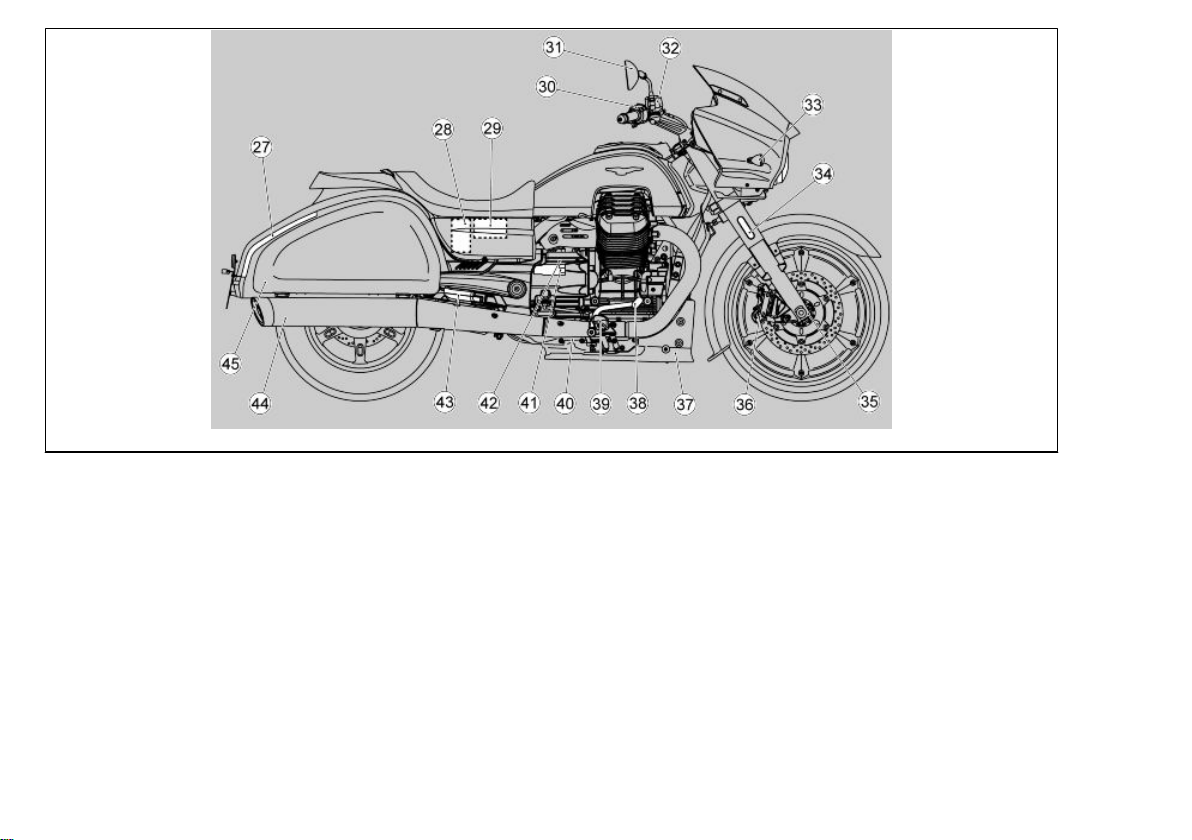
Arrangement of the main components (02_02)
Key:
1. Headlight unit
2. Front left turn indicator
3. Windscreen
4. Instrument panel
5. Left rear-view mirror
6. Clutch pump
7. Left light switch
8. Fuel tank cap
9. Fuel tank
10. Rider/passenger saddle
11. Brake light/left rear turn indicator
15

12. Left side saddle pannier
13. Licence plate light
14. Left silencer
15. Rear tone wheel
16. Rear ABS sensor
17. Left hand passenger footrest
18. Side stand
19. Left rider footrest
20. Gear lever
21. Engine oil level dipstick
22. Front left brake calliper
23. Front ABS sensor
24. Front tone wheel
25. Front left fork
26. Front left hand reflector
27. Brake light/right rear turn indicator
28. Battery
29. Fuse box
30. Right light switch
31. Right rear-view mirror
32. Front brake pump
33. Front right turn indicator
34. Front right hand reflector
35. Front right fork
36. Front right brake calliper
37. Engine cover
38. Rear brake lever
39. Right hand rider footrest
40. Rear brake pump
41. Rear shock absorbers regulator
42. Rear brake pump reservoir
43. Right hand passenger footrest
44. Right silencer
45. Right saddle bag
16
2 Vehicle
NOTE
ELECTRICAL COMPONENTS FUNCTION ONLY WHEN THE IGNITION KEY IS
SET TO "ON"
02_03
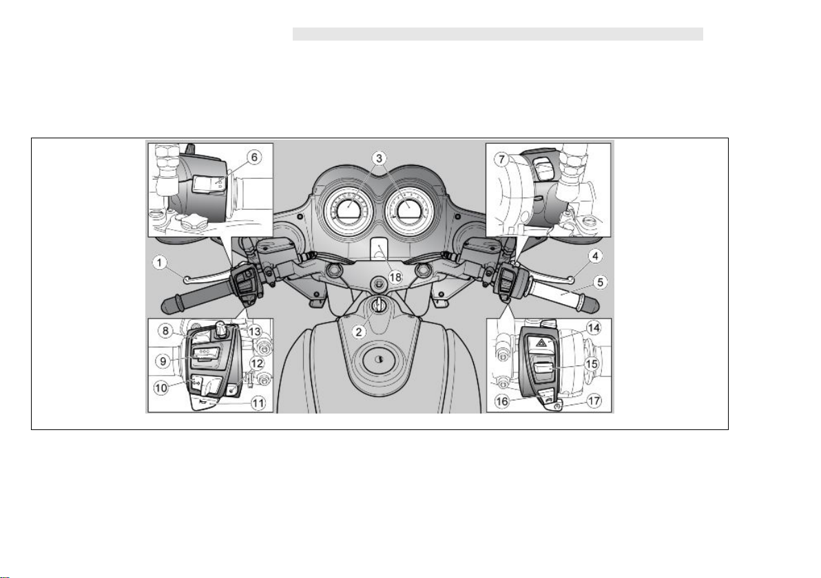
Dashboard (02_03)
Key:
1. Clutch control lever
2. Ignition switch /steering lock
17

3. Instruments and gauges
4. Front brake lever
5. Throttle grip
6. Light switch/high-beam flasher button
7. Daytime/night lights switch
8. "MUTE" button/radio menu
9. Left selector/cruise control
10. Turn indicator button
11. horn button
12. MGMP button
13. Radio selector
14. "HAZARD" emergency warning indicator button
15. Right selector/"MODE"
16. Engine stop switch
17. Start button/engine calibration
18. USB port
18
2 Vehicle
02_04
Instrument panel (02_04)
Dashboard key:
1. Speedometer
2. Multifunctional digital display
3. Warning lights
4. Rpm indicator
5. Multifunctional digital display
6. Warning lights
CAUTION
A PROLONGED DIRECT EXPOSURE OF THE DASHBOARD TO SUNLIGHT
WHILE THE ENGINE IS STOPPED MAY RESULT IN TEMPORARY REDUCTION
19

OF CONTRAST OF THE DISPLAY, ONCE ITS INTERNAL TEMPERATURE IS REDUCED IT WILL RECOVER.
The instrument panel has an immobilizer which prevents start-up in case the system
does not identify a key which has been programmed before.
The vehicle is supplied with two keys already programmed. The instrument panel accepts a maximum of four keys at the same time: contact an Official Moto Guzzi
Dealer to enable these keys or to disable a key that has been lost.
When starting the vehicle and approximately ten seconds after the key is set to ON,
viewing the information in the right display, the instrument panel requests a personal
five-digit code to be entered. This request is no longer displayed once the personal
code is entered. For code entering procedure, see the "CHANGE THE CODE" section.
It is important to remember the personal code because:
•
the vehicle can be started if the immobilizer system is faulty
•
the instrument panel need not be replaced should the ignition switch
be changed
•
new keys can be programmed
20
2 Vehicle
02_05
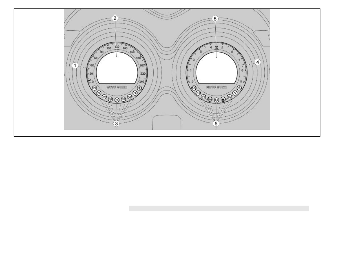
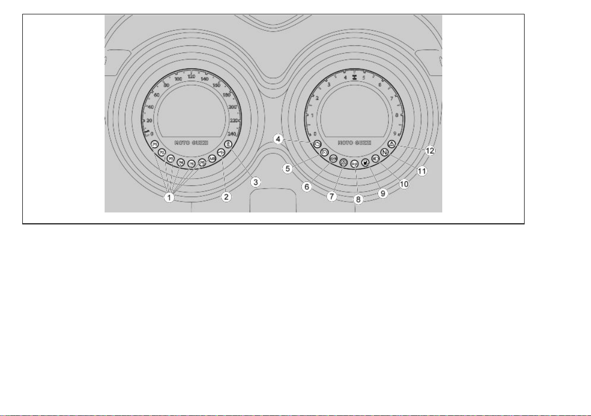
Light unit (02_05)
Left and right instrument key:
1. Radio station stored indicator lights (orange colour)
2. USB indicator light (green)
3. Bluetooth indicator light (blue)
4. MI warning light (orange)
5. Cruise control indicator light (green)
6. ABS (Anti-lock Braking System) warning light (orange)
7. MGCT (Moto Guzzi Traction Control) warning light (orange)
8. Turn indicator warning light (green)
9. Low fuel warning light (orange)
10. High beam warning light (blue)
11. Neutral gear warning light (green)
21
02_06
02_07
12. General alarm warning lamp (red)
Digital lcd display (02_06, 02_07, 02_08, 02_09, 02_10, 02_11,
02_12, 02_13, 02_14, 02_15, 02_16)
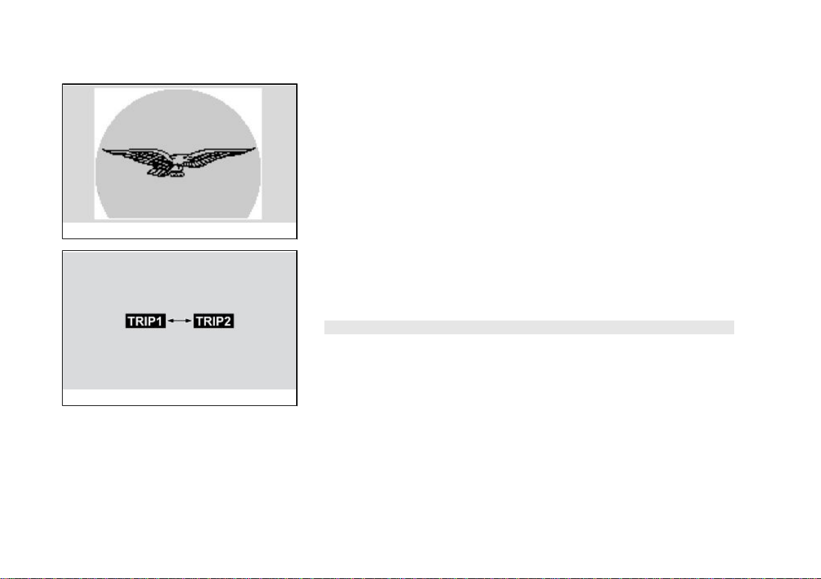
Turning the ignition key to the position "ON", in both instruments are switched on for
two seconds:
•
The Moto Guzzi logo;
•
all warning lights;
•
backlighting. When the daytime light function is activated the back lighting
switches off after the key is turned ON.
The dashboard needles move to maximum and back to zero.
After two seconds, all instruments immediately show the current value of the meas-
urements read.
With the key set to "KEY OFF" the general alarm warning light flashes to indicate
activation of the locking system. To minimise battery consumption the light stops
flashing after 50 hours.
NOTE
EVERY LONG PRESS UP OR DOWN OF THE "MODE" SELECTOR CAN CHANGE
FROM TRIP JOURNAL 1 (TRIP 1) TO TRIP JOURNAL 2 (TRIP 2).
22
2 Vehicle
02_08
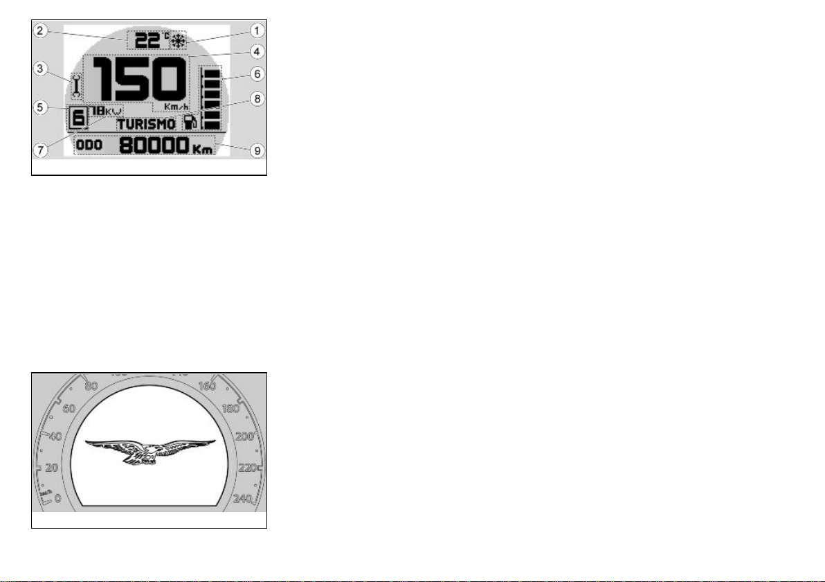
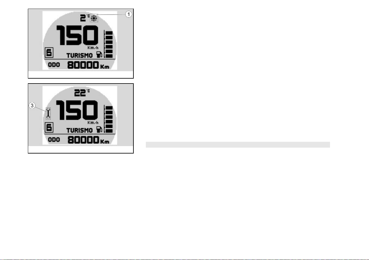
The standard settings that can be viewed on the right display are:
1. Ice warning icon (displayed at temperatures lower than 4 °C / 39.2°F)
2. Room temperature (displayed in °C or in °F);
3. Maintenance icon;
4. Speed (tachometer) (displayed in km/h or m/h);
5. Gear engaged;
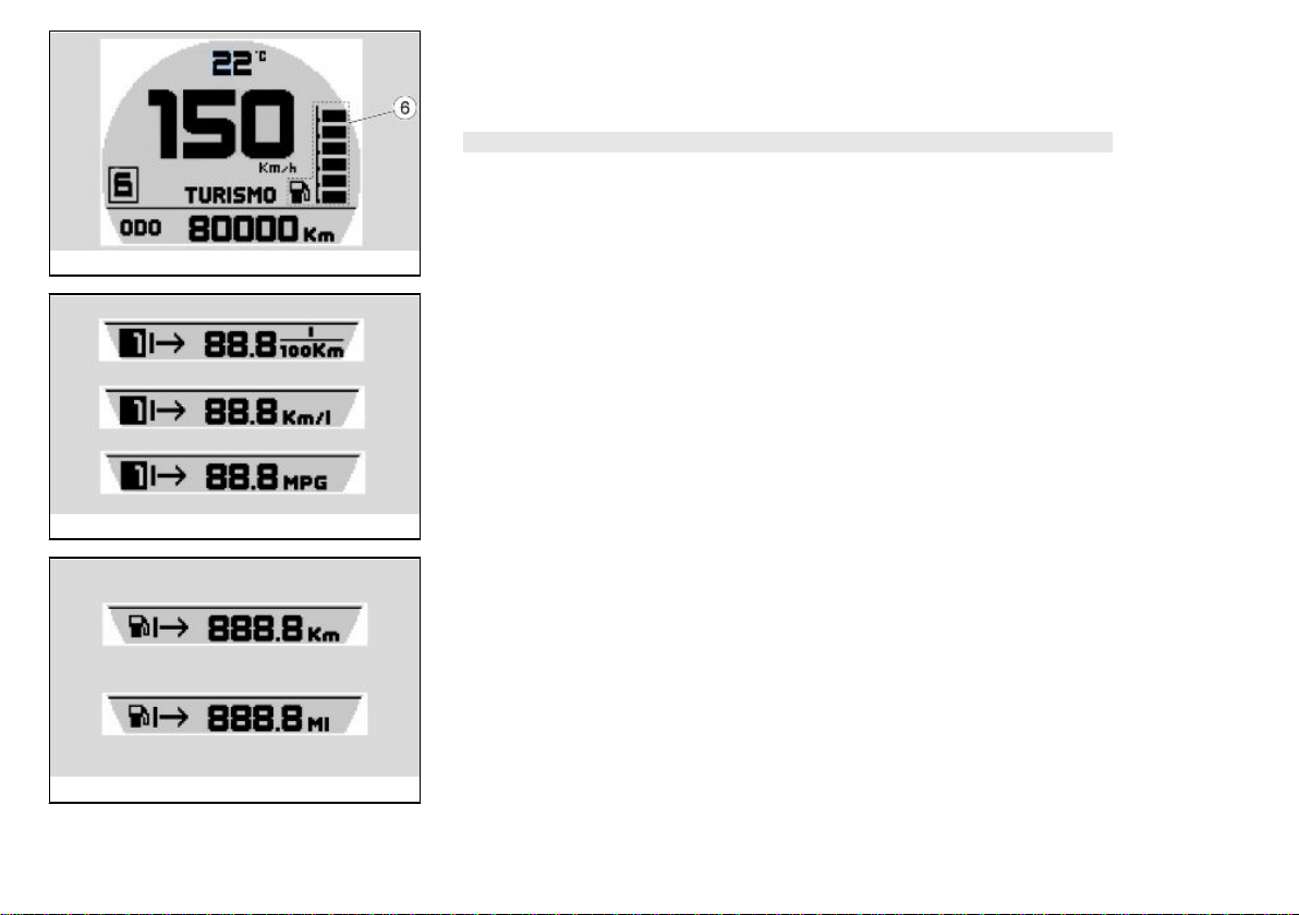
6. Fuel level;
7. Indication relative to the power limitation present in the control unit;
8. Selected engine map;
9. On-board computer travel journal or active alarms:
•
Total odometer
•
Trip odometer
•
Travelling time
•
Average speed
•
Average fuel consumption
•
Instant fuel consumption
•
Average in reserve
•
Battery voltage
•
Clock
Only with the vehicle at standstill:
•
Menu
•
MGCT (Moto Guzzi Traction Control)
The standard settings that can be viewed on the left display are:
1. FM radio
2. AM radio (enabled/disabled by the user)
3. USB audio (audio player for USB flash drives)
4. BT audio (audio connection for Bluetooth devices)
02_09
23
02_10
02_11
ICE ALARM
If the external temperature drops below 4 C° (39.2 F°), the ice symbol will appear in
the upper part of the right display (1). Therefore, be particularly careful when riding.
When this temperature rises the symbol will disappear.
MAINTENANCE ICON
The system displays the function as follows:
•
When the thresholds of the maintenance intervals have been exceeded an
adjustable spanner icon will appear (3) left of the right display. To reset the
service is necessary to take it to an Authorized Moto Guzzi Dealer and
Office.
Icon ignition: every 10,000 km (6,214 mi)
CAUTION
THE FIRST SCHEDULED SERVICE (1,500 km or 932.06 mi) MAINTENANCE ICON
WILL NOT BE ACTIVATED.
24
2 Vehicle
FUEL LEVEL
In the right display, it is visible the fuel level in the tank by means of a series of notches
(6).
NOTE
THE FUEL LEVEL INDICATION MAY CHANGE DEPENDING ON THE INCLINA-
TION OF THE MOTORCYCLE WHEN IT IS ON THE SIDE STAND AS OPPOSED
TO WHEN IT IS IN MOTION.
02_12
ACTUAL CONSUMPTION AND AVERAGE CONSUMPTION
In the right display it is possible to view the instantaneous fuel consumption and the
average consumption since the last reset of the trip journal.
02_13
AVERAGE IN RESERVE
After running for 2 km (1.24 mi) the fuel warning light appears on the right and display
the kilometres or miles on reserve. When the fuel warning light is on, it disappears
and reappears by pressing the right selector after 60 seconds.
02_14
25
02_15
02_16
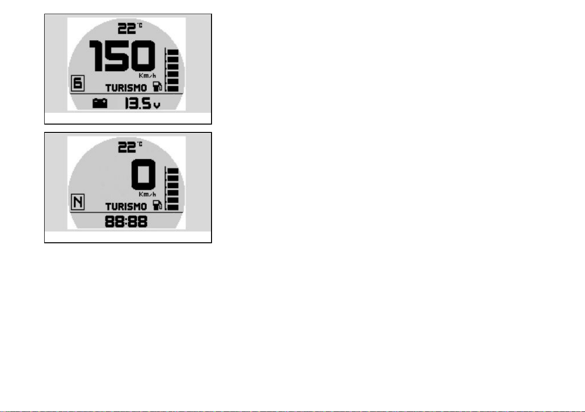
BATTERY VOLTAGE
In this mode the correct battery voltage can be viewed
TIME SETTINGS
The clock can be programmed with this option. Press and hold the "MODE" selector
in the centre to access the function. Within this function, each time the "MODE" selector is pressed up or down, the time will be increased or decreased by one hour.
Once 12 has been reached, the next press of the selector will return to 1.
Press the "MODE" selector to store the value and shift to the minute adjustment mode.
Each time the "MODE" selector is pressed up or down, the time will be increased or
decreased by one hour. Once 59 has been reached, the next press of the selector will
return to 0.
The procedure ends with a central long press of the switch "MODE" or automatically,
in the absence of input, after 5 seconds.
26
2 Vehicle
Alarms (02_17, 02_18, 02_19, 02_20, 02_21, 02_22, 02_23)
If an anomaly is detected, the bottom part of the right display shows a different icon
depending on the cause.
See an Official Moto Guzzi Dealer as soon as possible.
ALARM EMISSIONS
In case of a malfunction detected by the instrument panel or the electronic control unit
on the exhaust gas emissions, the steady light of the MI will appear. It is necessary to
consult an Official Moto Guzzi Dealer.
02_17
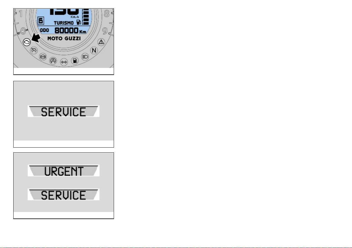
SERVICE ALARM
In case of malfunction detected by the instrument panel or the electronic control unit,
the word "SERVICE" will appear in the right display and the red light of general alarm
will be activated.
If there is an immobilizer failure at ignition, the instrument panel requests you to enter
a user code. If the current code is entered correctly, the instrument panel signals the
failure by displaying the word "SERVICE" in the right side of the display and the red
general warning light turns on.
02_18
URGENT SERVICE ALARM
A serious failure is signalled by a fast flashing (two flashes per second) of the general
warning light and by the "URGENT" and "SERVICE" words alternately being shown
on the right display. See an Official Moto Guzzi Dealer as soon as possible. In these
cases the ECU activates a safety procedure limiting vehicle performance in order to
allow the rider to go to an Official Moto Guzzi Dealer at a reduced speed. According
to the type of failure, performance can be limited in two ways: a) by reducing the
maximum torque produced; b) by keeping the engine at idle speed but slightly accelerated (during this operation, the throttle control is disabled).
02_19
27
02_20
02_21
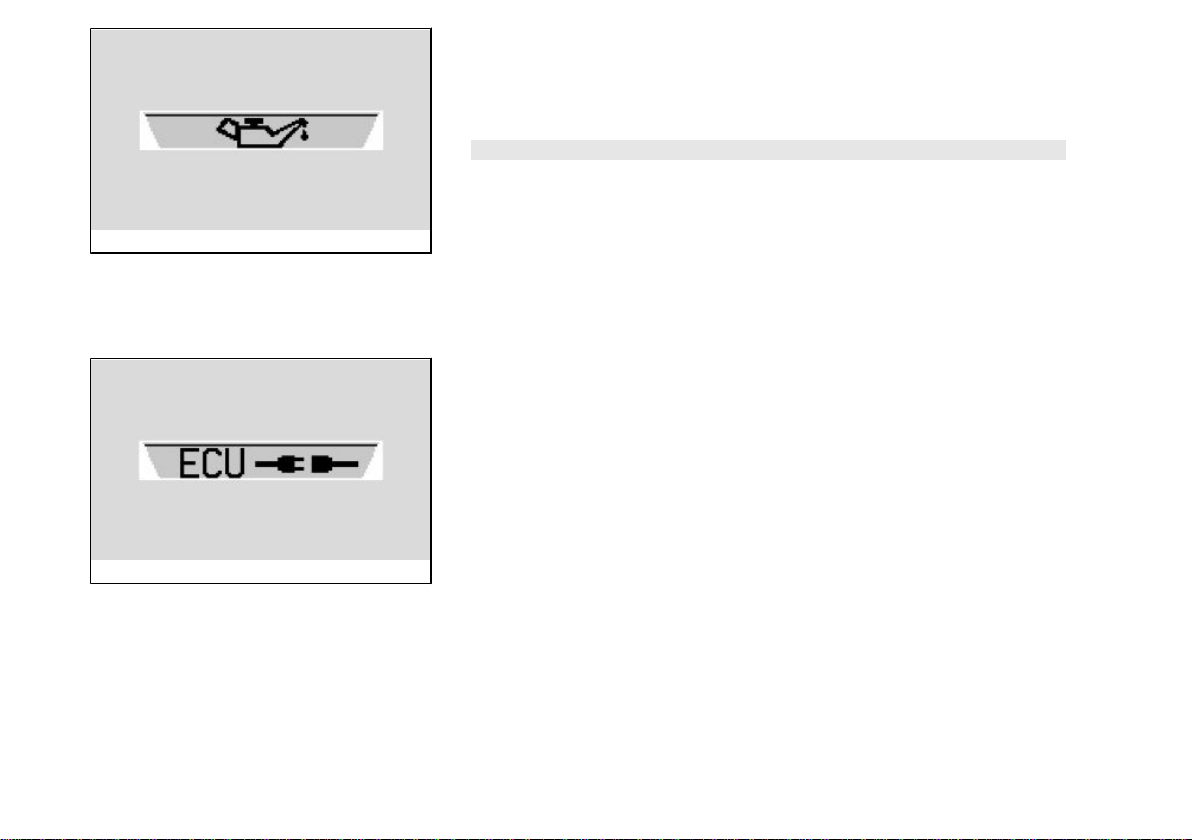
OIL ANOMALY
In case of failure of the oil pressure or the oil pressure sensor on the dashboard indicates the anomaly in the right display, the bulb and a fixed red light of general alarm
turns on.
CAUTION
IF THIS SIGNAL APPEARS WHEN THE KEY IS TURNED ON (STEADY LIGHTING
OF THE WARNING LIGHT), A SENSOR FAULT IS SIGNALLED AND THERE IS
NO IMMEDIATE DANGER FOR THE ENGINE.
IF THE SIGNAL APPEARS AFTER ENGINE IGNITION (THE WARNING LIGHT IS
FLASHING), AN OIL PRESSURE FAULT IS SIGNALLED; SWITCH OFF THE ENGINE IMMEDIATELY AND TAKE THE MOTORCYCLE TO AN Official Moto Guzzi
Dealer USING A ROADSIDE ASSISTANCE VEHICLE.
ELECTRONIC CONTROL UNIT DISCONNECTED ALARM
In case no connection is detected, the disconnection icon is displayed on the right
display and the red general warning light turns on in a solid manner to signal this
condition.
28
2 Vehicle
02_22
02_23
02_24
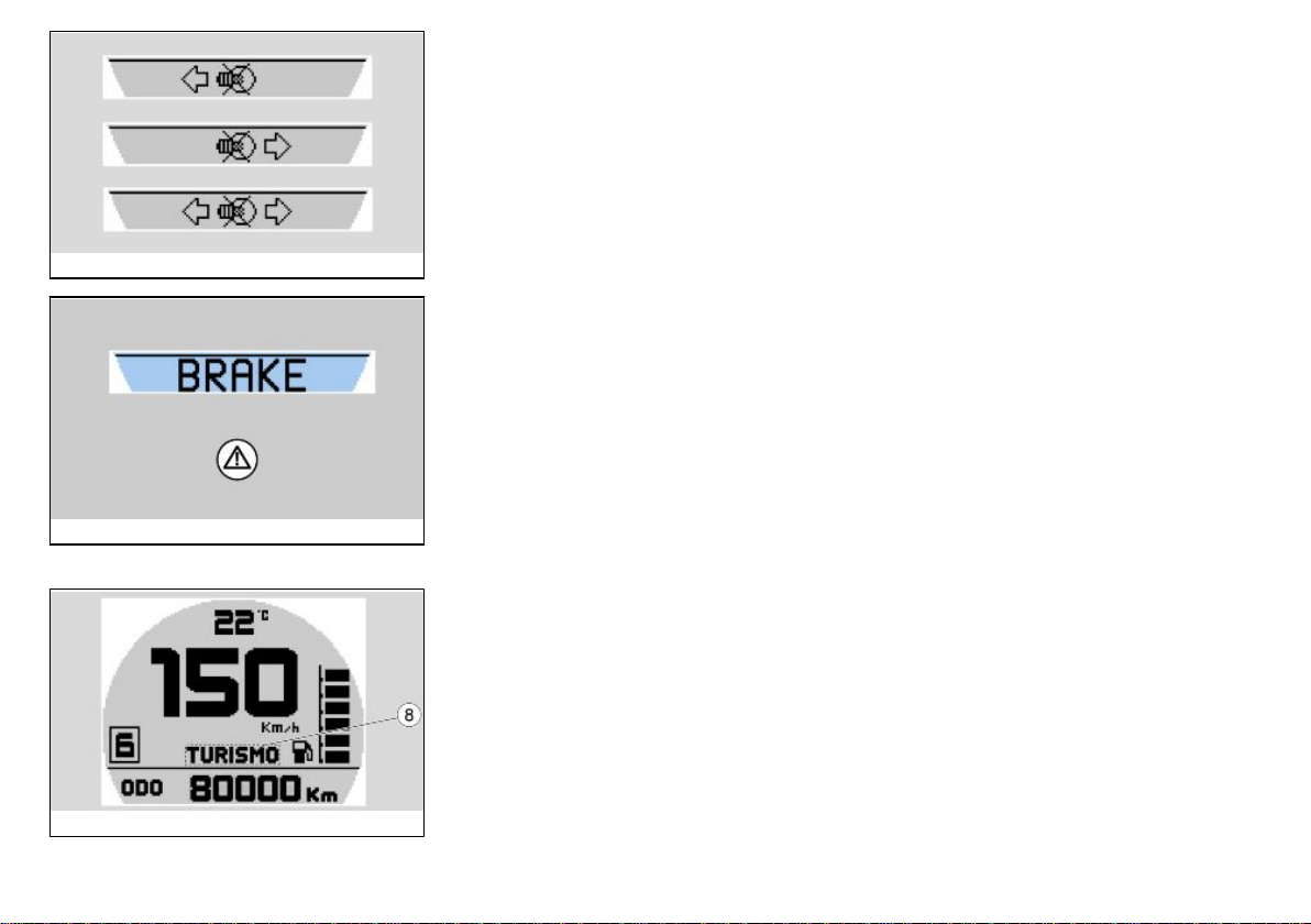
TURN INDICATORS MALFUNCTION
When the instrument panel detects a failing turn indicator, the warning light flashes
twice as fast and the problem is signalled on the right display.
ALARMS PROLONGED BRAKING
In case of accidental pressing of one of the two brakes for more than thirty seconds
while the vehicle is driving more than 20 Km/h (12.43 mph) the instrument panel shows
the fault displaying the wording "BRAKE" on the right display. If the accidental pressure
of one of the two brakes is maintained for more than sixty seconds, the instrument
panel shows the fault with the steady lighting of the red warning light and displaying
the wording "BRAKE" on the right display.
The message disappears from the instrument panel when the brakes are released.
With the motorcycle stopped, this alarm is deactivated.
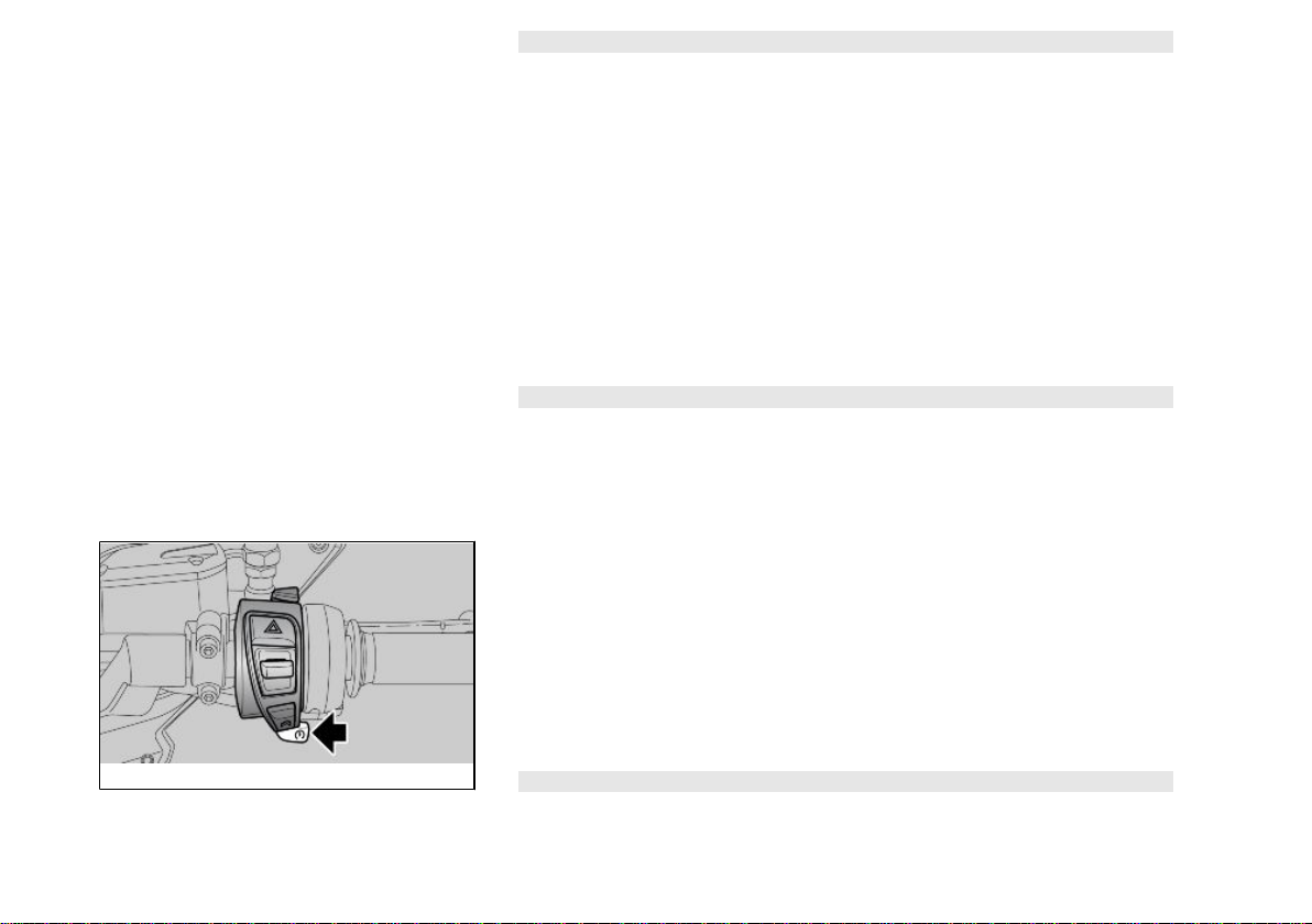
Mapping selection (02_24, 02_25)
The engine control unit has three different user selectable calibrations (8), displayed
as follows in the lower central part of the right display:
•
TURISMO
•
VELOCE
•
PIOGGIA
The TURISMO mode is designed for touring use of the vehicle.
VELOCE mode is the most reactive and is designed for sport use of the vehicle.
29
02_25
CAUTION
ONLY EXPERT RIDERS, RIDING ON ROADS WITH GOOD GRIP ARE ADVISED
TO USE THIS MODE. IT IS NOT RECOMMENDED FOR WET SURFACES AND/OR
ROADS WITH LOW GRIP.
The PIOGGIA mode is designed for use of the vehicle on wet surfaces or in conditions
of poor grip. The system reduces the maximum torque supplied by the engine and
smoothly delivers it so as to prevent loss of grip. In this mode, the vehicle performance
is limited, and therefore, the maximum speed cannot be reached.
EVEN IN THIS MODE, ALWAYS USE PARTICULAR CAUTION WHEN RIDING IN
POOR GRIP CONDITIONS.
The selection of the different engine maps is realized by pressing the starter button,
which may be used to select maps once 5 seconds have elapsed after engine start
CAUTION
THE SELECTION PROCEDURE AND MAP ACTIVATION IS EXCLUSIVE ONLY
WHEN THE ENGINE IS STARTED WITH THE THROTTLE GRIP RELEASED. IT IS
POSSIBLE TO ALSO PERFORM THIS PROCEDURE WITH THE MOTORCYCLE
RUNNING AND WITH THE THROTTLE GRIP RELEASED.
To change the calibration, proceed as follows:
•
Press the starter button once. The map currently in use is shown "in negative"
on the right display
•
Press the starter button again within 1.5 seconds of pressing the first time.
The next available map is shown in negative on the right display. If the button
is not pressed again within 1.5 seconds (which would select the next available
map), and the throttle grip is not used, the new map selection is shown in
positive on the display, indicating that the new map selection has been implemented.
CAUTION
IN CASE THE THROTTLE GRIP IS TURNED WHEN THE NEW MAPPING CHOSEN
IS HIGHLIGHTED "IN NEGATIVE" ON THE DISPLAY, HENCE STILL BEING AC-
30
 Loading...