

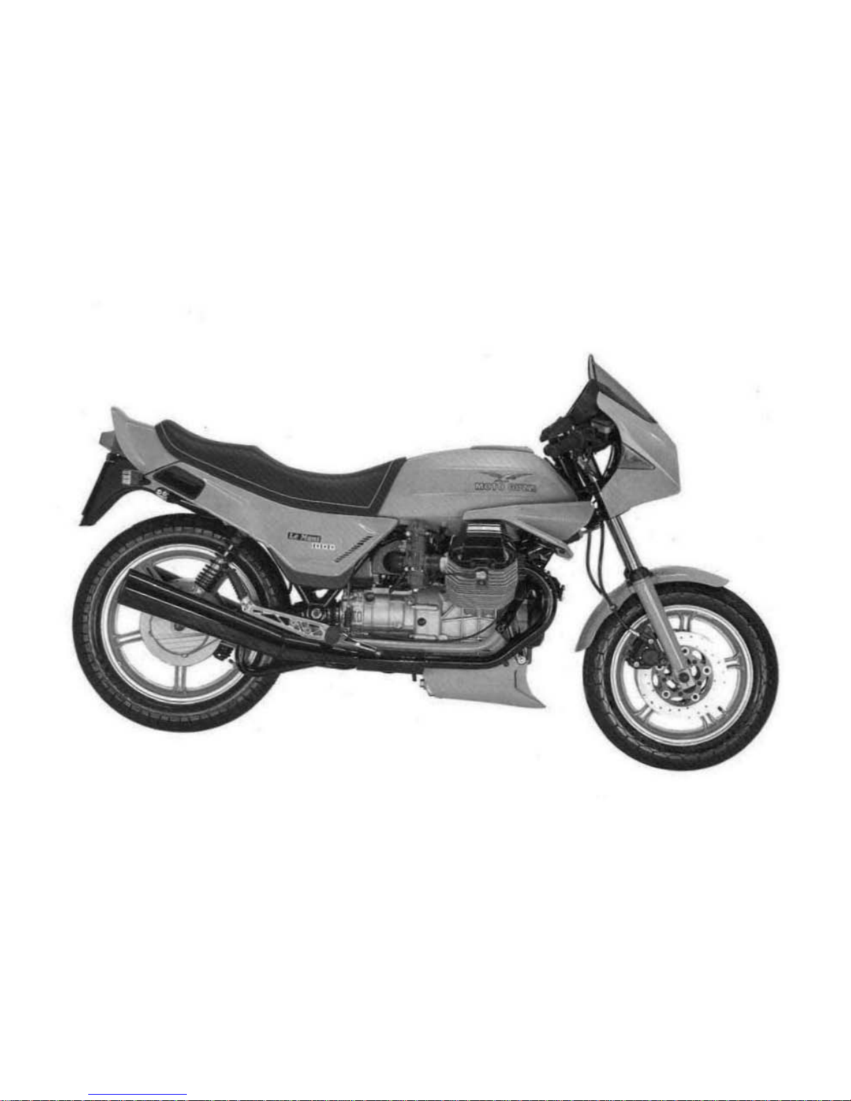
MOTO GUZZI Le mans 1000 Owner's Manual

Th.
mulltratlon
••
nd
description
.
In
thl.
booklet
....
IndIcloU". only
.nd
the
....
nul.ctu
...........
es
!belt
th.
tight
to
Introduce
.nw
modltlCIOtion
Mm., d •• m n.e
....
..,
lor
be"
••
perlonn.nce
or
for
conIltNCt"'.
or
eom
....
tcIal
.........
. without prtor notice.
SEI
_ WOTOGUlZl S.C>A·
T
~
Pv--..
CoM
2'800011
_ In 1taIy_ L.JIoIno.al9Mg
.....
- 1000 _
12Jf1~
Dear rider
First
of
all
we
wish to thank you for choosing this motorcycle.
By following the instructions outlined
in
this manual you will ensure
that your bike has
a long and troublefree life.
Before riding, please read this manual thoroughly
in
order
to
get to
know your motorcycle's features and
how
to use
it
safely.
All
major inspections and overhauls should be carried
out
by
our
dealers who have the facilities necessary
to
guarantee an efficient
and competent service.
Repairs
or
adjustments
by
any other than a Moto Guzzi dealer during
the warranty period could invalidate the warranty.
RIDING TECHNIQUE
Due
to
its
exceptional
features, this
motor-
cycle can
be
considered
as
in
the
same
class as racing machines, and should
be
ridden as such.
For
this
very
reason
it is
enjoyed
by
many
enthusiasts, but as with racing motor-
cycles, the riding technique must be
ap-
propriate.
Above
all else, given
that
the
carburetors
are fitted with accelerator pumps,
if
the
throttle isn't used correctly
in
relation to
the engine speed, any excess fuel ex-
pelled
by
the
carburetors
will
end
up
in
the
carburetor air intake filter.
When
travelling at low speeds, or more
correctly
at
low
engine
speeds,
the
throttle
must
be
used carefully,
since
the
excess
fuel might not be fully burned
by
the
en-
gine; at high engine speeds, even with
abrupt
accelerations, the
fuel
is
complete-
ly
burned, producing
that
exhilarating
and
distinguishing "pick-up
".
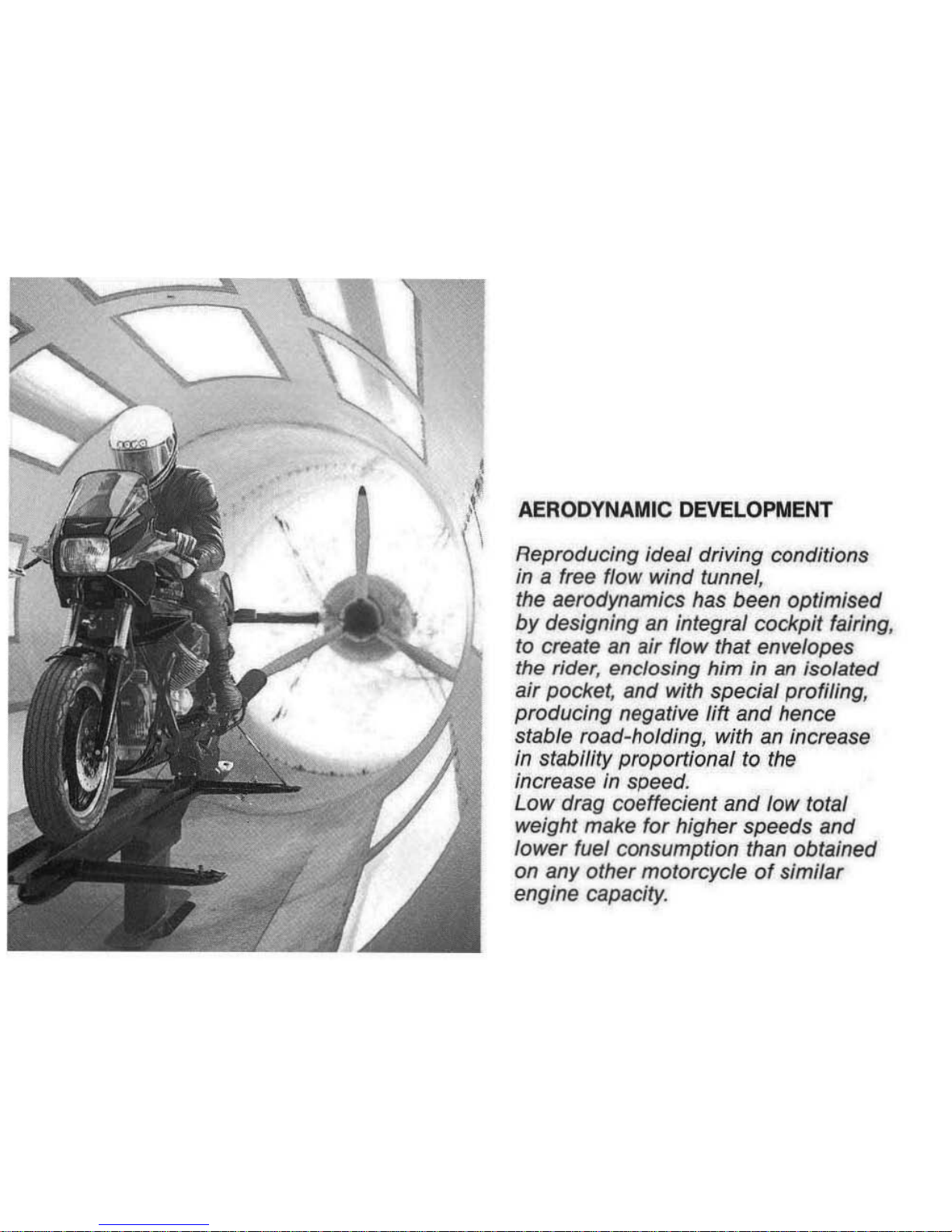
AERODYNAMIC DEVELOPMENT
Reproducing ideal driving conditions
in
a free flow
wind
tunnel,
the aerodynamics has been
optimised
by
designing an integral cockpit fairing,
to create
an
air flow that envelopes
the
rider, enclosing
him
in an
isolated
air
pocket, and with special profiling,
producing
negative lift
and
hence
stable road-holding, with an increase
in stability
proportional
to the
increase
in
speed.
Low
drag
coeffecient
and
low total
weight make for higher speeds and
lower
fuel consumption than obtained
on any other motorcycle
of
similar
engine capacity.
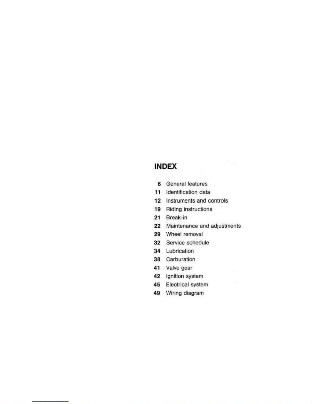
INDEX
6
General
features
11
Identification
data
12
Instrumen
ts
and
coolrols
"
Riding
instructions
21 Break-
in
22
Maintenance
and
adjustmen
ts
2.
Wheel remova
l
3'
Service sched
ule
3.
Lubrication
38
Garburatlon
.,
Valve
gear
.2
Ig
nition
system
.5
Electrical
system
••
Wiring
diagram
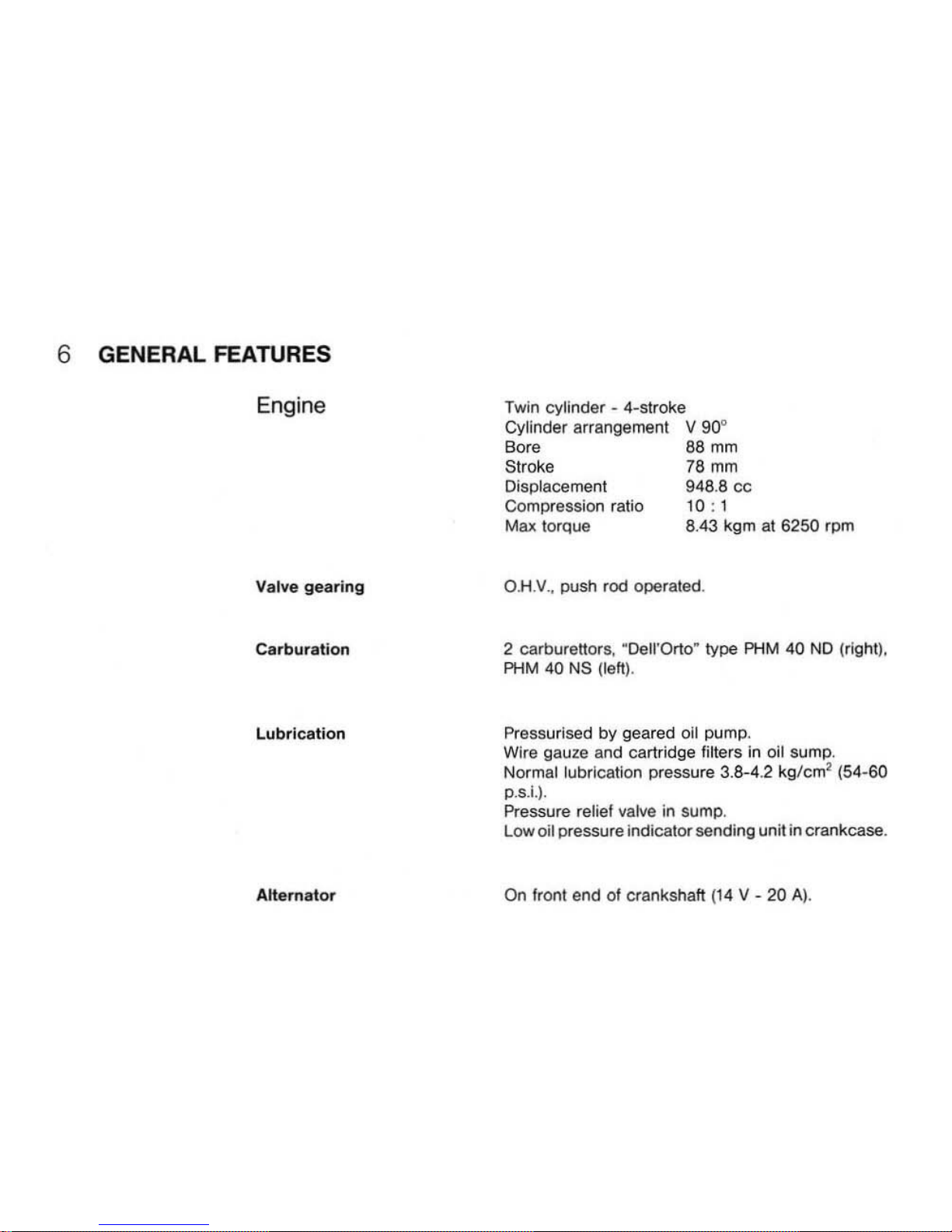
6 GENERAL FEATURES
Engine
Val
ve
gearing
Ca
rbur
atio
n
Lubrication
Alternator
Twin cylinder - 4-stroke
Cylinder arrangement V 90"
Bore
88
mm
Stroke
78
mm
Oisplacement 948.8
cc
Compression ratio
10
: 1
Max
torque 8.43 kgm
at
6250 rpm
OH
.V.,
push rod operated,
2 carburettors, "Dell'Orto·
type
PHM
40
NO
(right).
PHM
40
NS
(left
).
Pressurlsed by geared
aU
pump.
Wire gauze and cartridge filters
In
oit sump.
Normal lubrication pressure 3.8-4.2
kg/cm
~
(54
-60
D·sJ
,).
Pressure relief valve in sump .
low
ail pressure indicator sending unit in crankcase.
On
Iront end of crankshaft (
14
V - 20 A
).
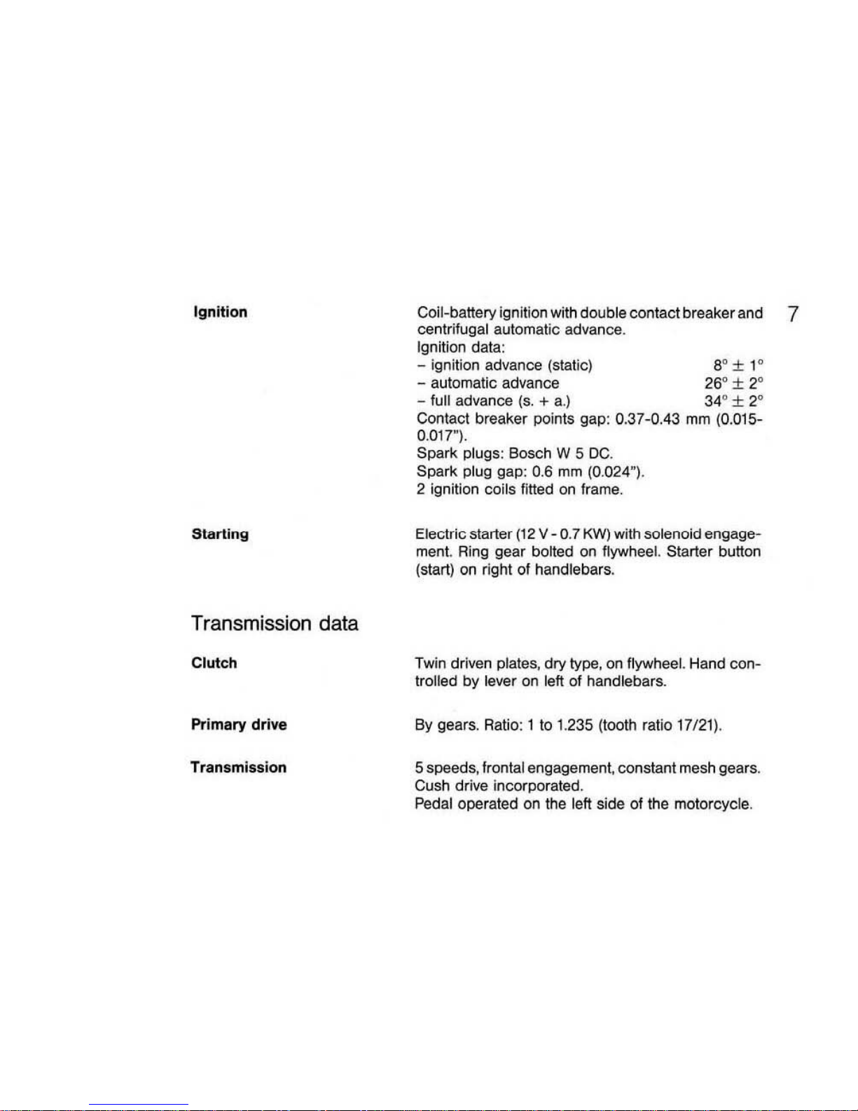
Ignition
Starting
Transmission data
Clutch
Primary drive
Transmission
Coli-battery ignition with double contact breaker and 7
centrilugal automatic advance.
Ignition data:
- ignition advance (static) So ± 1°
- automatic advance 26° ± 2°
- full advance
(so
+ a.) 34° ± 2°
Contact breaker points gap: 0.37-0.43
mm
(0.D15-
0.
017"
).
Spark plugs:
Bosch W 5 DC.
Spark plug gap: 0.6 mm (0.024").
2 ignition coils fined
on
frame.
Electric starter (12 V - 0.7 KW) with solenoid engage-
ment. Ring gear bolted on flywheel. Starter button
(start)
on
right of handlebars.
Twin driven plates, dry type, on flywhee
l.
Hand con-
troiled
by
lever on lett of handlebars.
By
gears. Ratio:
lto
1.235 (tooth rat
io
17/21
).
5 speeds, frontal engagement, constant mesh gears.
Cush drive incorporated.
Pedal operated on the left side of the motorcycle.
8
Final drive
Frame
Suspension
Wheels
Gear ratios:
Low gear = 1 to 2 (tooth ratio = 14/28)
2nd gear = 1 to 1.388 (tooth ratio = 18/25)
3rd gear = 1 to 1.0
47
(tooth ratio =
21122)
4th gear = 1 to 0.869 (Iooth ratio =
23120)
High gear = , to 0.750 (Iooth ratio = 28/21)
By
shaft with universal joint and gear set.
Ratio:
110 4.714 (tooth ratio = 7/33).
OVEl
rall
gear
ralios (Engine-wheel):
Low
gear
= 1 to
11
.647
2nd gear = 1 to 8.088
3rd
gear
= 1
10
6.100
4th
gear..: 1
to
5.063
High gear = 1 to 4.367
Cradle,
tubular
structure.
Front: telescopic fork "Moto Guzzi
patenled
~
with
air-hydraulic shock absorbers.
Rear: swing fork with adjustable coil springs con-
centric with hydraulic dampers.
Light alloy c03ting rim
dimcnoions
:
- front: 16
MT
2.50
H2
- rear:
18
MT 3.00
H2
Tires
Brakes
Dimensions
and
weights
Front: 1
20/80
V16
Rear:
130/80 V18
Type: Tubeless
or
tube~type
.
Front: two-piston fixed calliper, Iloating disc brake,
controlled by hand lever on
the
right side
01
handlebars. Hydraulic operation indipendent of the rear
brake ;
- disc
0 270 mm (
10
.63"):
- braking cylin
der
(1)
38
mm
(1.50");
- master cylinder
(1)
12.7
mm
(0.50").
Rear: two-piston fixed calliper, lIoatlng disc brake.
Pedal control
located
In
the center of the right side
01
the motocycle:
- disc 0 270
mm
(10
.63");
- braking cylinder 0
38
mm
(1.50");
- master cylinder 0 15.875
mm
(0.625") .
The rear brake Is connected via a hydraulic hose to
the front
left side brake, which has one set of compo-
nents
olthe
same dimensions as the hand controlled
front right side brake.
Wheelbase (loaded)
Length
Width
Height
Ground clearan
ce
Dry weight
1.514 m (59.6")
2.
160 m (85.0")
0.680
m (26.8")
1.220 m (48.0")
0.120
m (
4,r
)
215 kg (474 Ibs)
9
10
Performance
Top speed, solo riding: 230
km/h
(143 mph).
Fuel consumption: 5.4
11100
km (44 miles/US gal).
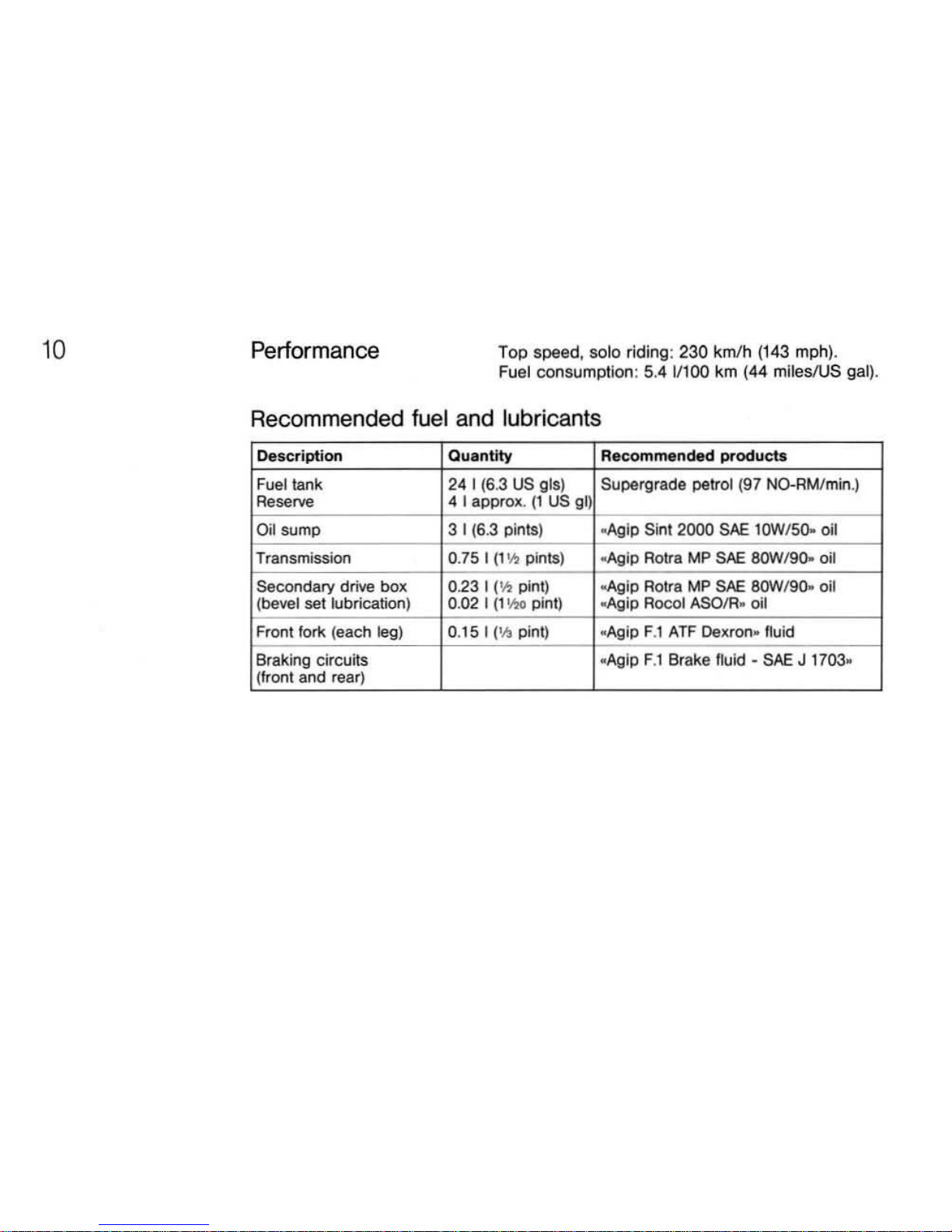
Recommended fuel and lubricants
Descri
ption
Quantity
R
ecommended
product
s
Fuel
tank 24 I (6.3
US
g15)
Supergrade
petrol (
97
NO-AM/min
.)
Reserve
4 I approx.
(1
US gl)
Oil
sump
3 t
(6.3
pints)
ooAgip
Sint 2000
SAE
lOW
/50-
oil
Transmission
0.75 I (1
'h
pints)
-Agip Roua
MP
SAE
8OWI9().. oil
Secondary drive
box
0.23 I 1
'.'.1
pint)
ooAgip
ROlf. MP SAE 8OWf90. oil
(bevel set lubrication) 0.02 I
(1
Y10
pint)
~Ip
Rocol ASOIR. oil
Fr
ont
for1o;
(each
leg) 0.15 I
1'
.'.1
pint) .
Aglp
F.l
ATF
Oexron. /!uid
Braking circuits
.Aglp F.l Brake
fluid·
SAE J 1703
.
(
Iront
and rear)
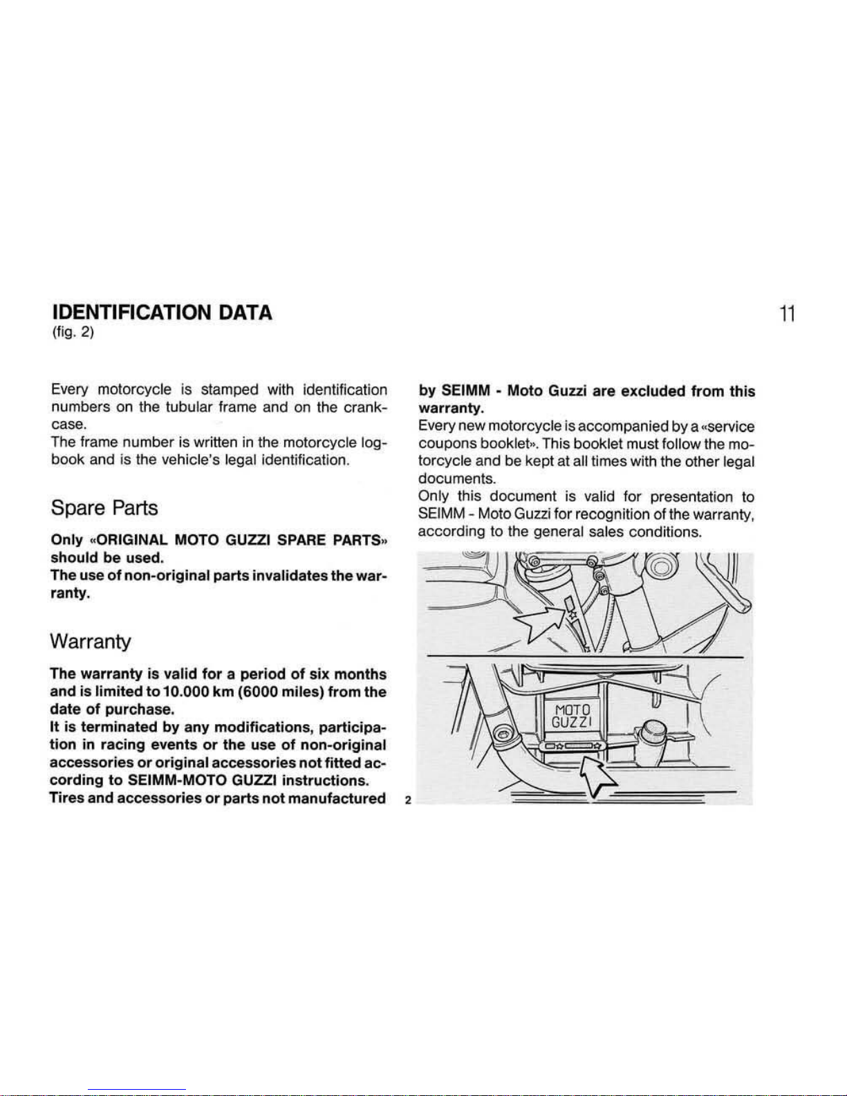
IDENTIFICATION DATA
(fig. 2)
Every motorcycle
is
stamped with identification
numbers on the tubular frame and on the
crank-
case.
The frame
number
is written in the motorcycle
log-
book and is the vehicle's legal identification.
Spare Parts
Only
~
ORIGINAL
MOTO GUZZI SPARE PARTS»
should
be
used.
The use
of
non-original parts invalidates the war-
ranty .
Warranty
The
warranty
is valid
for a period
of
six
months
and is
limited tol0.000
km
(6000 miles) from
the
date
of
purchase.
It
is
terminated
by
any
modifications, participa-
tion
in racing events
or
the
use
of
non-original
accessories
or
original
accessories
not
fitted
ac-
cording
to
SEIMM·MOTQ GUZZI
instructions
.
Tires
and
accessories
or
parts
not
manufactured
,
by SEIMM • Moto Guzzi are excluded
from
this
warranty.
Every new
motorcycle is accompanied by a "service
coupons booklet ... This booklet must follow the mo-
torcycle and be kept at all times with the other legal
documents.
Only this document is valid for presentation to
SEIMM - Molo Guzzi for recognition of the warranty,
according to the
general sales conditions.
11

12
INSTRUMENTS
AND
CONTROLS
In
strument panel (fig.
3)
1 Ignillon key switch:
~OFF
M
In line with mark MG
.:
machine stationary. key
removable (no contacts).
M
A~
in
line with mark
_eM
(turned
cloc
kwise): ma-
chine
ready to
be
started. All cir
cuits
-ON
·,
Key
nol
removable.
..
8.
In
line
with
mark..v
(turned clockwise) machine
stationary. With switch
«Aoo
ollig. 4
In
.
PARK
. posi-
3
lion, pandng light
..QN
••
Key removable.
2 Voltmeter.
3 Tachometer.
4 Speedometer-odometer.
S Zero reset for trip
odometer
.
6 Indicator
light (green) for left turn signal.
7 Indicator light (green) for right turn signal.
8
Indicator
light (blue)
'Of
high beam ON.
9 Indicator light (green)
lor
parking lights
ON
.
10 Indicator light (green -NElfI'RAl,o
).
On wtlen
transmission Is
in
neutral.
11
Ind
icator
light (red)
lor
generator
output
Should
go
off
upon
increasing engine
speed
,
12
Indicator light (red) for oil pressure. Goes off
when
oil pressure
Is
sufficient to assure engine
lu·
bricalion .lf It
does
not, then the
011
pressure is
incor·
rect: if this
happens
the engine should
be
s
topped
Immediately
and
checked.
13 Indicator
light (red) shows low level
oflluld
In
the
fronlleft
and rear
brake
fluid master
cylinder·reser·
voir
. If It
comes
ON then
lOP
up
the fluid reservoir. At
the
same time
check
that there are
no
leaks
in
the
hydraulic
circuit
14
Hazard
waming
lights switch (located
on
the
bra·
eket to left
of
headlight).
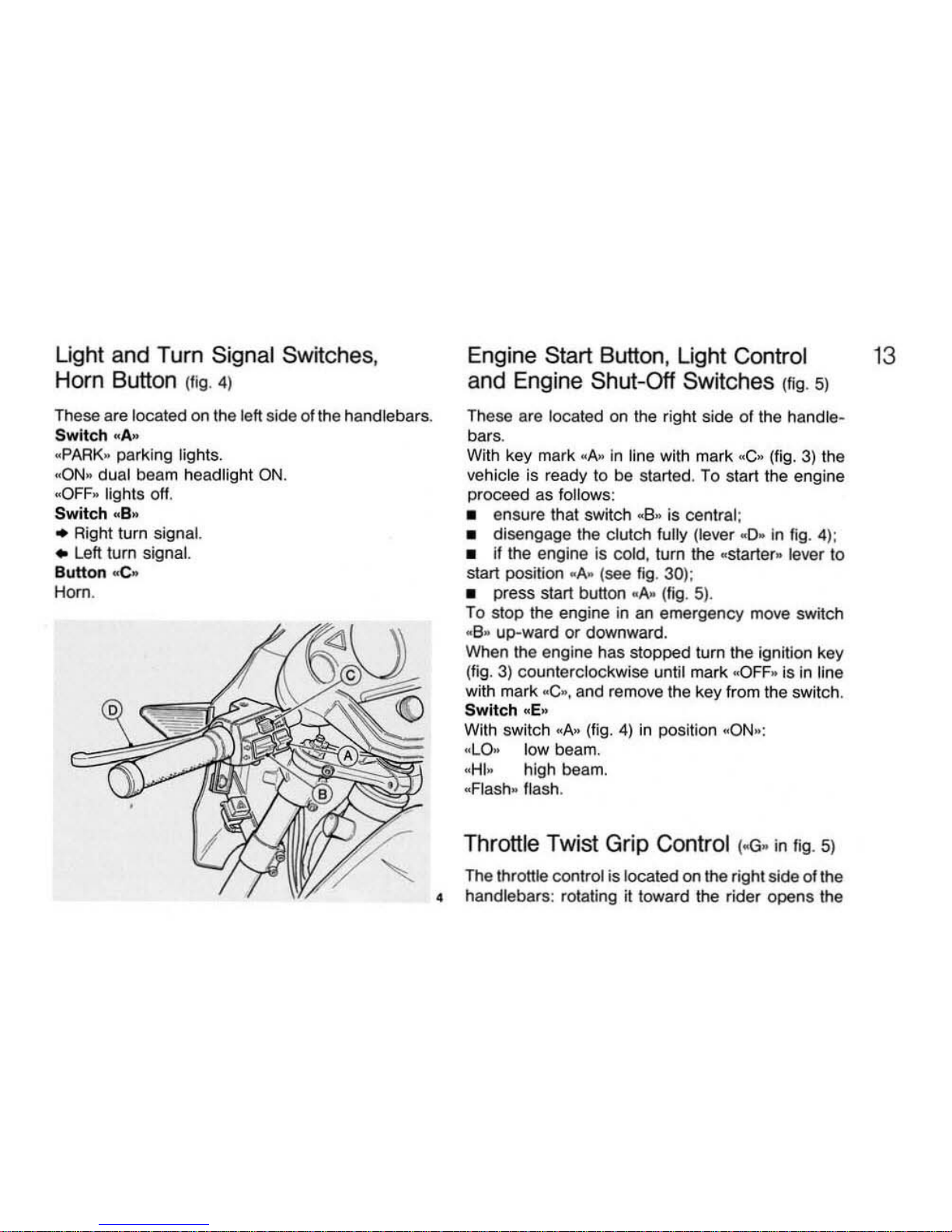
Light and Turn Signal Switches,
Horn Button (fig. 4)
These are
located
on
the left side of the handlebars.
Switch
..
A
~
~
PARK
.
parking lights.
~ON.
dual beam headlight
ON.
«OFF
. lights off.
Switch
~B"
• Aightturn signal.
• Left turn signal.
Button
..
e.
Horn.
Engine Start Button, Light Control
and Engine Shut-Off Switches Ilig.
5)
These are located on the right side
01
the handlebars.
With key mark
..
A.
in
line with mark "C. (tig. 3) the
vehicle is ready to
be
started. To start the engine
proceed as follows:
•
ensure that switch
..
8" is central:
• disengage the clutch fully (lever
,,
0-
in
tig
. 4
):
• it the engine is cold, turn the
..
starter_ lever to
start position
..
A. (see
fig
. 30):
• press start button .
A-
(fig.
5)
.
To
slop the engine
in
an
emergency move switch
,,
8. up-ward or downward.
When the engine has stopped turn the ignition key
(fig.
3)
counterclockwise until mark
..
OFF
. is
in
line
with mark .C
..
, and remove the key Irom the switch.
Switch
.. E ..
With switch
.A"
(fig.
4)
in
poSilion
..
ON
..
:
"LO.
low beam.
"HI. high beam.
"Flash
..
flash.
Throttle Twist Grip Control loG-
In
fig
.
5)
The throttle control is located on t
he
right side
01
the
4
ha
ndlebars : rotating it toward the rider opens the
13
14
throttle; the opposite closes
it
Adjustment
01
the twist
grip
travel is
by
means
01
screw
..
D~.
To retard the twist grip return adjust screw -00.
Clutch Control Lever H)" In
f'9
_ 4)
The
lever is located on the left side of the handle-
bars; it should be used only during
mow
off
and to
change gears.
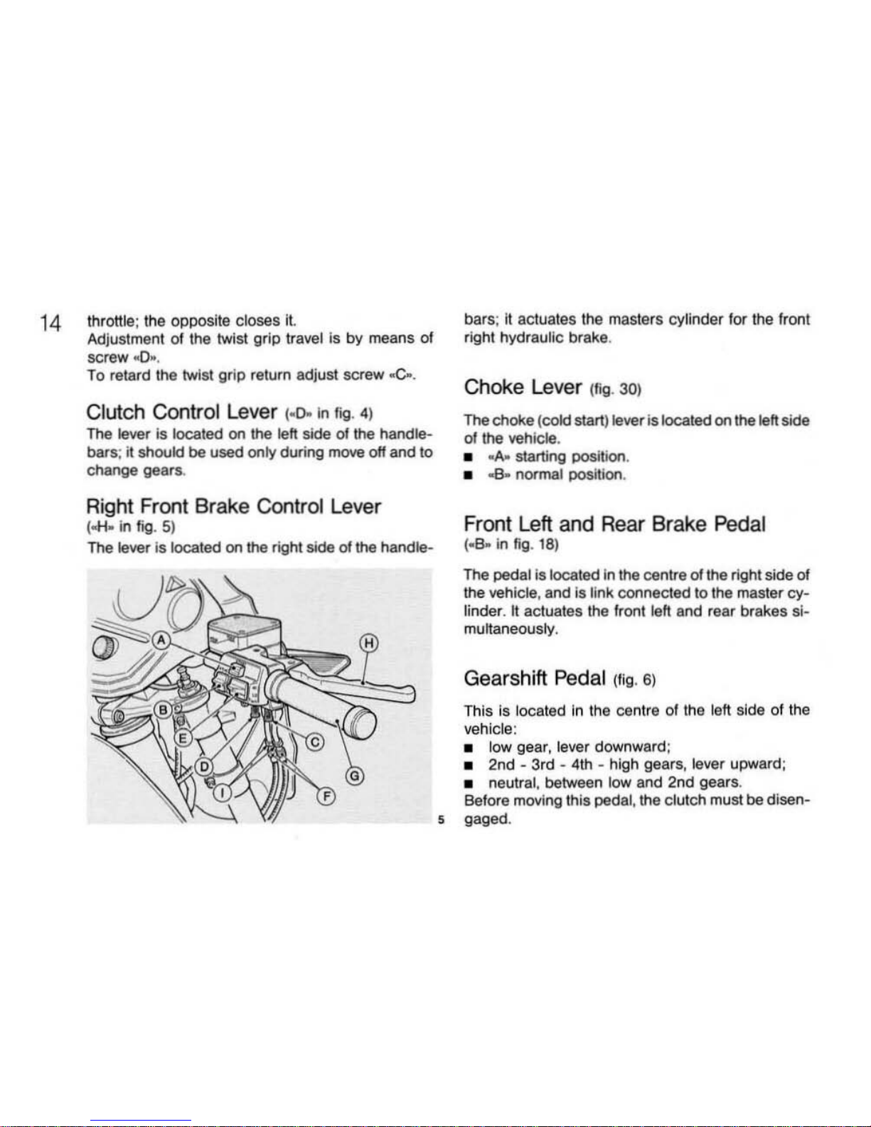
Ri
ght
Front Brake Control Lever
(
oo:H
..
in
fig. 5)
The lever is located
on
the right side of
the
handle-
ba
rs;
II
actuates the masters cylinder for the front
right hydraulic brake.
Chok
e Lever (Iig. 30)
The
ChOke
(cold start) !ever is located
on
the left
side
01
the vehicle.
•
-A-
starting positi
on
.
•
..a
..
normal position .
Fro
nt
Left and Rear Brake Pedal
(_
B" In fig. 18)
The pedal is located
In
the centre of the right side
of
the vehicle , and Is
link
connected to the
maslercy-
linder. " actuates the front left and feaf brakes
si-
multaneously,
Gearshift Pedal (fig.
6)
This Is located
In
the centra of the lett side of the
vehicle:
• low gear, lever downward;
•
2nd·
3rd
- 4th - high
gears
, lever upward:
• neutral , between
low
and 2nd gears .
Before moving this
pedal, the clutch must
be
disen-
5 gaged .
Fuel Filler
Cap
(1". 7)
To
acce
ss
the fuel
fillercap
..s-
tum
key..A,. cJock-
wise, then
lift
cover
..c-
.
NOTE· Any fuel spilt should
be wiped
off immed
ia-
tely to prevent permanent damage
to
the tank's
paint
.
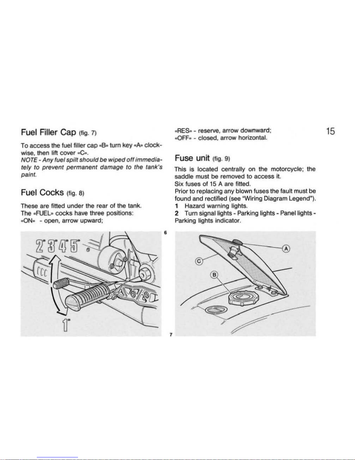
Fuel Cocks (fig. 8)
These are fitted
under
the
rear
of the
lank
.
The
.
A.JE~
cocks
have
three posltioos:
~ON·
- open, arrow upward;
•
,
«RES- -
reserve, arrow
downward
:
-oFF- -
closed, arrow
hOrizontaL
Fuse unit (fig.
9)
This is located centrally on the motorcycle; the
saddle must
be
removed to
access
It.
Six fuses
of
15
A are
lined
.
Prior to replacing
any
blown fuses the fault must be
f
ound
and rectified (see
~
Wiring
Diagram Legend").
1 Hazard warning lights.
2 Turn signal lights - Parking lights - Panel lights Parking lights I
ndicator
.
15
 Loading...