


MOTO GUZZI DESEA AGRADECERLE
por haber elegido uno de sus productos. Hemos preparado este manual para permitirle apreciar todas sus cualidades. Le aconsejamos que lea todo
su contenido antes de conducir por primera vez. Contiene información, consejos y advertencias para el uso de su vehículo; asimismo, descubrirá
características, detalles y soluciones que lo convencerán de lo acertado de su elección. Estamos seguros de que teniendo todo esto en cuenta, le
resultará fácil conocer su nuevo vehículo, el cual podrá disfrutar por mucho tiempo con total satisfacción. La presente publicación es parte integrante
del vehículo y en caso de venderlo debe ser entregada al nuevo propietario.
MOTO GUZZI WOULD LIKE TO THANK YOU
for choosing one of its products. We have drawn up this booklet to provide a comprehensive overview of your vehicle's quality features. Please read it
carefully before riding the vehicle for the first time. It contains information, tips and precautions for using your vehicle. It also describes features, details
and devices to assure you that you have made the right choice. We believe that if you follow our suggestions, you will soon get to know your new vehicle
well and will use it for a long time at full satisfaction. This booklet is an integral part of the vehicle, and should the vehicle be sold, it must be transferred
to the new owner.
Griso 8V-1200
Ed. 04 2008

Las instrucciones de este manual han sido preparadas principalmente para suministrar una guía simple y clara de uso; se indican también las
operaciones de mantenimiento básico y los controles periódicos que se deberán realizar en los CONCESIONARIOS o Talleres autorizados Moto
Guzzi. Además, el manual contiene las instrucciones para que pueda realizar algunas reparaciones simples. Las operaciones que no se describen
explícitamente en esta publicación requieren la disponibilidad de herramientas especiales y/o de conocimientos técnicos específicos. para su ejecución
recomendamos dirigirse a los CONCESIONARIOS o Talleres autorizados Moto Guzzi.
The instructions in this manual have been prepared to offer mainly a simple and clear guide to its use; it also describes routine maintenance procedures
and regular checks that should be carried out on the vehicle at an authorised Moto Guzzi Dealer or Workshop, The booklet also contains instructions
for simple repairs. Any operations not specifically described in this booklet require the use of special tools and/or particular technical knowledge; for
these operations, please take your vehicle to an authorised Moto Guzzi Dealer or Workshop.
2

Seguridad de las personas
Personal safety
El no-cumplimiento total o parcial de estas prescrip-
ciones puede comportar peligro grave para la incolu-
midad de las personas.
Salvaguardia del ambiente
Indica el comportamiento correcto para que el uso del
vehículo no cause ningún daño a la naturaleza.
Integridad del vehículo
El no-cumplimiento total o parcial de estas prescrip-
ciones comporta el peligro de serios daños al vehículo
e incluso la caducidad de la garantía.
Las señales indicadas previamente son de gran importancia. Sirven para evidenciar las partes del manual que requieren de más atención. Como se puede
observar, cada señal está compuesta por un símbolo
gráfico diferente, para facilitar y agilizar la búsqueda
de los temas en las diversas áreas. Antes de poner
en marcha el motor, leer atentamente este manual,
especialmente el apartado "CONDUCCIÓN SEGURA". Su seguridad y la de los demás no depende
solamente de la rapidez de sus reflejos y agilidad, sino también del conocimiento del vehículo, de su eficiencia y del conocimiento de las reglas fundamentales para la CONDUCCIÓN SEGURA. Por lo tanto, le
recomendamos familiarizarse con el vehículo lo suficiente como para circular por la carretera con total
control y seguridad. IMPORTANTE Este manual se
debe considerar como parte integrante del vehículo y
debe acompañarlo en caso de venta.
Failure to completely observe these instructions will
result in serious risk of personal injury.
Safeguarding the environment
Sections marked with this symbol indicate the correct
use of the vehicle to prevent damaging the environ-
ment.
Vehicle intactness
The incomplete or non-observance of these regula-
tions leads to the risk of serious damage to the vehicle
and sometimes even the invalidity of the guarantee.
The sings above are very important. They are used to
highlight those parts of the booklet that should be read
with particular care. As you can see, each sign consists of a different graphic symbol, making it quick and
easy to locate the various topics. Before starting the
engine, read this manual carefully, particularly the
"SAFE RIDING" section. Your safety as well as other's
does not only depend on the quickness of your reflexes and agility, but also on how well you know your
vehicle, its efficiency and your knowledge of the rules
for SAFE RIDING. For your safety, get to know your
vehicle well so as to safely ride and master it in road
traffic IMPORTANT This booklet is an integral part of
the vehicle, and should the vehicle be sold, it must be
transferred to the new owner.
3

4

INDICE
INDEX
NORMAS GENERALES................................................................. 9
Introducción.............................................................................. 10
Monóxido de carbono............................................................... 10
Combustible............................................................................. 11
Componentes calientes............................................................ 12
Puesta en marcha y Conducción............................................. 12
Testigos.................................................................................... 13
Aceite motor y aceite cambio usados...................................... 14
Líquido frenos y embrague...................................................... 15
Electrolito y gas hidrógeno de la batería.................................. 16
Soporte..................................................................................... 17
Comunicación de los defectos que influyen en la seguridad
................................................................................................. 18
VEHÌCULO...................................................................................... 19
Ubicación componentes principales............................................ 21
Tablero de instrumentos.............................................................. 23
Conjunto de instrumentos............................................................ 24
Grupo testigos............................................................................. 25
Representacion visual digital por cristales liquidos..................... 26
Teclas de mando...................................................................... 27
Funciones avanzadas.............................................................. 30
Conmutador de encendido....................................................... 39
Bloqueo del volante.................................................................. 40
Luces de aparcamiento............................................................ 41
Pulsante claxon........................................................................... 42
Conmutador intermitentes........................................................... 42
Commutador luces....................................................................... 43
Pulsador ráfaga luz de carretera................................................. 43
Pulsante arranque....................................................................... 44
Interruptor parada motor.............................................................. 44
Abertura sillín........................................................................... 45
GENERAL RULES............................................................................ 9
Foreword.................................................................................... 10
Carbon monoxide....................................................................... 10
Fuel............................................................................................ 11
Hot components......................................................................... 12
Start off and Riding..................................................................... 12
Warning lights............................................................................. 13
Used engine oil and gearbox oil................................................. 14
Brake and clutch fluid................................................................. 15
Battery hydrogen gas and electrolyte......................................... 16
Stand.......................................................................................... 17
Reporting of defects that affect safety........................................ 18
VEHICLE........................................................................................... 19
Arrangement of the main components........................................... 21
Dashboard..................................................................................... 23
Instrument panel............................................................................ 24
Light unit........................................................................................ 25
Digital lcd display........................................................................... 26
Control buttons........................................................................... 27
Advanced functions.................................................................... 30
Ignition switch............................................................................. 39
Locking the steering wheel......................................................... 40
Parking lights.............................................................................. 41
Horn button.................................................................................... 42
Switch direction indicators............................................................. 42
High/low beam selector.................................................................. 43
Passing button............................................................................... 43
Start-up button............................................................................... 44
Engine stop switch......................................................................... 44
Opening the saddle.................................................................... 45
Glove/tool kit compartment......................................................... 46
5

Compartimiento porta-doc./kit herramientas............................ 46
La identificación........................................................................... 47
Fijación maletero......................................................................... 48
EL USO........................................................................................... 49
Controles..................................................................................... 50
Abastecimiento............................................................................ 53
Regulación amortiguadores traseros........................................... 55
Regulación horquilla delantera.................................................... 58
Regulación leva freno delantero.................................................. 61
Regulación leva embrague.......................................................... 62
Rodaje......................................................................................... 62
Arranque dificultoso..................................................................... 64
Aparcamiento............................................................................... 65
Escape catalítico.......................................................................... 66
Soporte........................................................................................ 68
Sugerencias contra los robos...................................................... 69
Normas basicás de seguridad..................................................... 71
EL MANTENIMIENTO.................................................................... 79
Premisa........................................................................................ 80
Control del nivel de aceite motor.............................................. 81
Llenado de aceite motor........................................................... 82
Sustitución aceite motor........................................................... 84
Nivel aceite cardán...................................................................... 87
Nivel aceite cambio...................................................................... 87
Neumáticos.................................................................................. 88
Desmontaje bujía......................................................................... 91
Desmontaje filtro aire................................................................... 94
Control nivel aceite frenos........................................................... 95
Llenado liquido circuito de frenos............................................. 95
Control líquido embrague............................................................ 96
Reposición líquido embrague................................................... 97
Puesta en servicio de una batería nueva................................. 97
Comprobacion del nivel del electrolito..................................... 98
Recarga batería....................................................................... 99
Larga inactividad.......................................................................... 100
Fusibles....................................................................................... 101
Bombillas..................................................................................... 105
Regulación proyector............................................................... 108
Indicadores de dirección delanteros............................................ 110
Identification................................................................................... 47
Luggage anchor point.................................................................... 48
USE................................................................................................... 49
Checks........................................................................................... 50
Refuelling....................................................................................... 53
Rear shock absorbers adjustment................................................. 55
Front fork adjustment..................................................................... 58
Justering af greb til forbremse....................................................... 61
Clutch lever adjustment................................................................. 62
Running in...................................................................................... 62
Difficult start up.............................................................................. 64
Parking........................................................................................... 65
Catalytic silencer............................................................................ 66
Stand.............................................................................................. 68
Suggestion to prevent theft............................................................ 69
Basic safety rules........................................................................... 71
MAINTENANCE................................................................................ 79
Foreword........................................................................................ 80
Engine oil level check................................................................. 81
Engine oil top-up........................................................................ 82
Engine oil change....................................................................... 84
Universal joint oil level................................................................... 87
Gearbox oil level............................................................................ 87
Tyres.............................................................................................. 88
Spark plug dismantlement............................................................. 91
Removing the air filter.................................................................... 94
Checking the brake oil level........................................................... 95
Braking system fluid top up........................................................ 95
Checking clutch fluid...................................................................... 96
Topping up clutch fluid............................................................... 97
Use of a new battery.................................................................. 97
Checking the electrolyte level..................................................... 98
Charging the battery................................................................... 99
Long periods of inactivity............................................................... 100
Fuses............................................................................................. 101
Lamps............................................................................................ 105
Headlight adjustment.................................................................. 108
Front direction indicators................................................................ 110
Rear optical unit............................................................................. 110
6

Grupo óptico trasero.................................................................... 110
Indicadores de dirección traseros................................................ 111
Luz placa..................................................................................... 111
Espejos retrovisores.................................................................... 112
Freno de disco delantero y trasero.............................................. 113
Inactividad del vehiculo................................................................ 115
Limpieza del vehiculo.................................................................. 117
Transporte................................................................................... 122
DATOS TÉCNICOS........................................................................ 123
Herramientas en dotación............................................................ 131
EL MANTENIMIENTO PROGRAMADO......................................... 133
Tabla manutención programada.................................................. 134
PREPARACIONES ESPECIALES................................................. 143
Índice accesorios......................................................................... 144
Rear turn indicators........................................................................ 111
Number plate light.......................................................................... 111
Rear-view mirrors........................................................................... 112
Front and rear disc brake............................................................... 113
Periods of inactivity........................................................................ 115
Cleaning the vehicle....................................................................... 117
Transport........................................................................................ 122
TECHNICAL DATA........................................................................... 123
Kit equipment................................................................................. 131
PROGRAMMED MAINTENANCE.................................................... 133
Scheduled maintenance table........................................................ 134
SPECIAL FITTINGS.......................................................................... 143
Accessories index.......................................................................... 144
7

8

Griso 8V-1200
Cap. 01
Normas generales
Chap. 01
General rules
9

Introducción
Foreword
NOTA
EL TIEMPO PREVISTO PARA REALI-
ZAR LAS OPERACIONES DE MANTENIMIENTO, DEBE SER REDUCIDO A
LA MITAD SI EL VEHÍCULO SE UTILIZA EN ZONAS LLUVIOSAS, POLVORIENTAS, EN RECORRIDOS ACCIDENTADOS O EN CONDUCCIÓN
DEPORTIVA.
Monóxido de carbono
Si es necesario hacer funcionar el motor
para poder efectuar alguna operación,
asegurarse de que esto ocurra en un espacio abierto o en un ambiente ventilado
de manera adecuada. Nunca hacer funcionar el motor en espacios cerrados. Si
se trabaja en un espacio cerrado, utilizar
un sistema de evacuación de los humos
de escape.
ATENCIÓN
LOS HUMOS DE ESCAPE CONTIENEN
MONÓXIDO DE CARBONO, UN GAS
VENENOSO QUE PUEDE PROVOCAR
LA PÉRDIDA DE CONOCIMIENTO E
INCLUSO LA MUERTE.
NOTE
CARRY OUT THE MAINTENANCE OP-
ERATIONS AT HALF THE INTERVALS
SHOWN IF THE VEHICLE IS USED IN
WET OR DUSTY AREAS, OFF ROAD
OR FOR SPORTS APPLICATIONS.
Carbon monoxide
If you need to keep the engine running in
order to perform a procedure, please ensure that you do so in an open or very well
ventilated area. Never let the engine run
in an enclosed area. If you do work in an
enclosed area, make sure to use a
smoke-extraction system.
CAUTION
EXHAUST EMISSIONS CONTAIN
CARBON MONOXIDE, A POISONOUS
GAS WHICH CAN CAUSE LOSS OF
CONSCIOUSNESS AND EVEN
DEATH.
10

Combustible
1 Normas generales / 1 General rules
Fuel
ATENCIÓN
EL COMBUSTIBLE UTILIZADO PARA
LA PROPULSIÓN DE LOS MOTORES
DE EXPLOSIÓN ES EXTREMADAMENTE INFLAMABLE Y PUEDE RESULTAR EXPLOSIVO EN DETERMINADAS CONDICIONES. CONVIENE
REALIZAR EL REABASTECIMIENTO
Y LAS OPERACIONES DE MANTENIMIENTO EN UNA ZONA VENTILADA Y
CON EL MOTOR APAGADO. NO FUMAR DURANTE EL REABASTECIMIENTO NI CERCA DE LOS VAPORES
DE COMBUSTIBLE, Y EVITAR ABSOLUTAMENTE EL CONTACTO CON
LLAMAS DESNUDAS, CHISPAS Y
CUALQUIER OTRA FUENTE QUE PODRÍA HACER QUE EL COMBUSTIBLE
SE ENCIENDA O EXPLOTE.
NO ARROJAR EL COMBUSTIBLE AL
MEDIO AMBIENTE.
MANTENER FUERA DEL ALCANCE
DE LOS NIÑOS.
CAUTION
FUEL USED TO POWER INTERNAL
COMBUSTION ENGINES IS HIGHLY
FLAMMABLE AND CAN BECOME EXPLOSIVE UNDER SPECIFIC CONDITIONS. IT IS THEREFORE RECOMMENDED TO CARRY OUT REFUELLING AND MAINTENANCE PROCEDURES IN A VENTILATED AREA WITH
THE ENGINE SWITCHED OFF. DO
NOT SMOKE DURING REFUELLING
AND NEAR FUEL VAPOURS, AVOIDING ANY CONTACT WITH NAKED
FLAMES, SPARKS OR OTHER SOURCES WHICH MAY CAUSE THEM TO
IGNITE OR EXPLODE.
DO NOT DISPOSE OF FUEL IN THE
ENVIRONMENT.
KEEP OUT OF THE REACH OF CHILDREN
11

LA CAÍDA O LA EXCESIVA INCLINACIÓN DEL VEHÍCULO PUEDEN PRODUCIR DERRAMES DE COMBUSTIBLE.
VEHICLE FALL OR EXCESSIVE INCLINATION CAN CAUSE FUEL TO SPILL
OUT.
Componentes calientes
El motor y los componentes de la instalación de escape alcanzan altas temperaturas y permanecen calientes durante
un cierto período, incluso después de
apagar el motor. Para manipular estos
componentes, utilizar guantes aislantes
o esperar hasta que el motor y la instalación de escape se hayan enfriado.
Puesta en marcha y
Conducción
ATENCIÓN
SI DURANTE LA CONDUCCIÓN, EN EL
TABLERO SE ENCIENDE EL TESTIGO
DE RESERVA DE COMBUSTIBLE,
SIGNIFICA QUE COMIENZA A UTILIZARSE LA RESERVA.
REPONER COMBUSTIBLE LO ANTES
POSIBLE.
12
Hot components
The engine and the exhaust system components get very hot and remain in this
condition for a certain time interval after
the engine has been shut off. Before handling these components, make sure that
you are wearing insulating gloves or wait
until the engine and the exhaust system
have cooled down.
Start off and Riding
CAUTION
IF THE LOW FUEL WARNING LIGHT
ON THE INSTRUMENT PANEL TURNS
ON WHILE RIDING, THIS MEANS THE
RESERVE IS BEING USED.
REFUEL AS SOON AS POSSIBLE.

1 Normas generales / 1 General rules
Testigos
Warning lights
SI EL TESTIGO DE ALARMA Y EL ICONO DE DIAGNÓSTICO "SERVICE" SE
ENCIENDEN DURANTE EL FUNCIONAMIENTO NORMAL DEL MOTOR,
SIGNIFICA QUE LA CENTRALITA
ELECTRÓNICA HA DETECTADO ALGUNA ANOMALÍA.
EN MUCHOS CASOS EL MOTOR CONTINÚA FUNCIONANDO CON RENDIMIENTO LIMITADO; DIRIGIRSE INMEDIATAMENTE A UN CONCESIONARIO
OFICIAL Moto Guzzi PARA REALIZAR
LAS INTERVENCIONES PREVISTAS
EN LA FICHA DE MANTENIMIENTO
PERIÓDICO.
SI EL TESTIGO DE ALARMA Y EL ICONO EN LA PANTALLA PRESIÓN ACEITE MOTOR PERMANECEN ENCENDIDOS, O SE ENCIENDEN DURANTE EL
FUNCIONAMIENTO NORMAL DEL
MOTOR, SIGNIFICA QUE LA PRESIÓN
DEL ACEITE EN EL CIRCUITO ES INSUFICIENTE.
EN ESTE CASO CONTROLAR EL NIVEL DE ACEITE DEL MOTOR Y SI NO
IF THE ALARM WARNING LIGHT AND
THE "SERVICE" DIAGNOSIS ICON
TURN ON DURING REGULAR ENGINE
OPERATION, IT MEANS THAT THE
ELECTRONIC CONTROL UNIT HAS
DETECTED A FAILURE.
IN MANY CASES THE ENGINE CONTINUES TO WORK WITH LIMITED
PERFORMANCE; TAKE YOUR VEHICLE TO AN Official Moto Guzzi Dealer TO CARRY OUT THE MAINTENANCE OPERATIONS SPECIFIED IN
THE PERIODIC MAINTENANCE
CHART.
IF THE ALARM WARNING LIGHT AND
THE ICON ON THE ENGINE OIL PRESSURE DISPLAY REMAIN ON, OR IF
THEY TURN ON DURING ENGINE
REGULAR OPERATION, IT MEANS
THAT THE OIL PRESSURE IN THE
CIRCUIT IS TOO LOW.
IN THIS CASE, CHECK THE ENGINE
OIL LEVEL AND IF IT IS NOT CORRECT, STOP THE ENGINE IMMEDIATELY AND TOP-UP WITH OIL.
13

FUERA EL CORRECTO, DETENERLO
INMEDIATAMENTE Y RESTABLECER
EL NIVEL.
DIRIGIRSE A UN CONCESIONARIO
OFICIAL Moto Guzzi PARA QUE CONTROLE LA INSTALACIÓN.
CONTACT AN OFFICIAL Moto Guzzi
Dealer TO CHECK THE CIRCUIT.
Aceite motor y aceite cambio
usados
ATENCIÓN
EN CASO DE INTERVENCIONES DE
MANTENIMIENTO, SE RECOMIENDA
EL USO DE GUANTES DE LÁTEX.
EL ACEITE MOTOR O DEL CAMBIO
DE VELOCIDADES PUEDE PROVOCAR SERIOS DAÑOS EN LA PIEL SI
SE MANIPULA POR MUCHO TIEMPO
Y COTIDIANAMENTE.
SE RECOMIENDA LAVAR CUIDADOSAMENTE LAS MANOS DESPUÉS DE
HABERLO EMPLEADO.
ENTREGARLO O HACERLO RETIRAR
POR LA EMPRESA DE RECUPERACIÓN DE ACEITES USADOS MÁS
CERCANA O POR EL PROVEEDOR.
NO ARROJAR EL ACEITE AL MEDIO
AMBIENTE
14
Used engine oil and gearbox
oil
CAUTION
IT IS ADVISABLE TO WEAR LATEX
GLOVES WHEN SERVICING THE VEHICLE.
THE ENGINE OR GEARBOX OIL MAY
CAUSE SERIOUS INJURIES TO THE
SKIN IF HANDLED FOR PROLONGED
PERIODS OF TIME AND ON A REGULAR BASIS.
WASH YOUR HANDS CAREFULLY
AFTER HANDLING OIL.
HAND THE OIL OVER TO OR HAVE IT
COLLECTED BY THE NEAREST USED
OIL RECYCLING COMPANY OR THE
SUPPLIER.
DO NOT DISPOSE OF OIL IN THE ENVIRONMENT

1 Normas generales / 1 General rules
MANTENER FUERA DEL ALCANCE
DE LOS NIÑOS.
KEEP OUT OF THE REACH OF CHILDREN
Líquido frenos y embrague
Líquido frenos y embrague
LOS LÍQUIDOS DE FRENOS Y DEL
EMBRAGUE PUEDEN DAÑAR LAS
SUPERFICIES PINTADAS, DE PLÁSTICO O DE GOMA. CUANDO SE REALIZA EL MANTENIMIENTO DEL SISTEMA DE FRENOS O DEL EMBRAGUE, PROTEGER ESTOS COMPONENTES CON UN PAÑO LIMPIO.
UTILIZAR SIEMPRE ANTIPARRAS DE
PROTECCIÓN PARA REALIZAR EL
MANTENIMIENTO DE ESTOS SISTEMAS. EL LÍQUIDO DE FRENOS Y DEL
EMBRAGUE SON SUMAMENTE DAÑINOS PARA LOS OJOS. EN CASO DE
CONTACTO ACCIDENTAL CON LOS
OJOS, ENJUAGAR INMEDIATAMENTE CON ABUNDANTE AGUA FRÍA Y
LIMPIA, Y CONSULTAR INMEDIATAMENTE A UN MÉDICO.
MANTENER FUERA DEL ALCANCE
DE LOS NIÑOS.
Brake and clutch fluid
Brake and clutch fluid
BRAKE AND CLUTCH FLUIDS CAN
DAMAGE THE PLASTIC OR RUBBER
PAINTED SURFACES. WHEN SERVICING THE BRAKING SYSTEM OR THE
CLUTCH SYSTEM PROTECT THESE
COMPONENTS WITH A CLEAN
CLOTH. ALWAYS WEAR PROTECTIVE GOGGLES WHEN SERVICING
THESE SYSTEMS. BRAKE AND
CLUTCH FLUIDS ARE EXTREMELY
HARMFUL FOR YOUR EYES. IN THE
EVENT OF ACCIDENTAL CONTACT
WITH YOUR EYES, RINSE THEM IMMEDIATELY WITH ABUNDANT COLD,
CLEAN WATER AND SEEK MEDICAL
ADVICE.
KEEP OUT OF THE REACH OF CHILDREN
15

Electrolito y gas hidrógeno de
la batería
Battery hydrogen gas and
electrolyte
ATENCIÓN
EL ELECTROLITO DE LA BATERÍA ES
TÓXICO, CÁUSTICO Y EN CONTACTO
CON LA EPIDERMIS PUEDE CAUSAR
QUEMADURAS, YA QUE CONTIENE
ÁCIDO SULFÚRICO. USAR GUANTES
BIEN ADHERENTES E INDUMENTARIA DE PROTECCIÓN AL MANIPULAR
EL ELECTROLITO DE LA BATERÍA. SI
EL LÍQUIDO DEL ELECTROLITO ENTRA EN CONTACTO CON LA PIEL,
LAVAR CON ABUNDANTE AGUA
FRESCA. ES MUY IMPORTANTE PROTEGER LOS OJOS, YA QUE INCLUSO
UNA CANTIDAD MINÚSCULA DE ÁCIDO DE LA BATERÍA PUEDE CAUSAR
CEGUERA. SI EL LÍQUIDO ENTRA EN
CONTACTO CON LOS OJOS, LAVAR
CON ABUNDANTE AGUA DURANTE
QUINCE MINUTOS, LUEGO DIRIGIRSE INMEDIATAMENTE A UN OCULISTA. SI SE INGIERE LÍQUIDO ACCIDENTALMENTE, BEBER ABUNDANTE CANTIDAD DE AGUA O LECHE,
CONTINUAR CON LECHE DE MAGNESIA O ACEITE VEGETAL, LUEGO DIRIGIRSE INMEDIATAMENTE A UN MÉDICO. LA BATERÍA EMANA GASES
EXPLOSIVOS: CONVIENE MANTENERLA ALEJADA DE LLAMAS, CHISPAS, CIGARRILLOS Y CUALQUIER
OTRA FUENTE DE CALOR. PREVER
CAUTION
BATTERY ELECTROLYTE IS TOXIC,
CORROSIVE AND AS IT CONTAINS
SULPHURIC ACID, IT CAN CAUSE
BURNS WHEN IN CONTACT WITH
THE SKIN. WHEN HANDLING BATTERY ELECTROLYTE, WEAR TIGHTFITTING GLOVES AND PROTECTIVE
APPAREL. IN THE EVENT OF SKIN
CONTACT WITH THE ELECTROLYTIC
FLUID, RINSE WELL WITH PLENTY OF
CLEAN WATER. IT IS PARTICULARLY
IMPORTANT TO PROTECT YOUR
EYES BECAUSE EVEN TINY
AMOUNTS OF BATTERY ACID MAY
CAUSE BLINDNESS. IF THE FLUID
GETS INTO CONTACT WITH YOUR
EYES, WASH WITH ABUNDANT WATER FOR FIFTEEN MINUTES AND
CONSULT AN EYE SPECIALIST IMMEDIATELY. IF THE FLUID IS ACCIDENTALLY SWALLOWED, DRINK LARGE
QUANTITIES OF WATER OR MILK,
FOLLOWED BY MILK OF MAGNESIA
OR VEGETABLE OIL AND SEEK MEDICAL ADVICE IMMEDIATELY. THE
BATTERY RELEASES EXPLOSIVE
GASES; KEEP IT AWAY FROM
FLAMES, SPARKS, CIGARETTES OR
ANY OTHER HEAT SOURCES. ENSURE ADEQUATE VENTILATION
16

1 Normas generales / 1 General rules
UNA AIREACIÓN ADECUADA AL
REALIZAR EL MANTENIMIENTO O LA
RECARGA DE LA BATERÍA.
MANTENER FUERA DEL ALCANCE
DE LOS NIÑOS.
EL LÍQUIDO DE LA BATERÍA ES CORROSIVO. NO DERRAMARLO NI DESPARRAMARLO, ESPECIALMENTE
SOBRE LAS PARTES DE PLÁSTICO.
ASEGURARSE DE QUE EL ÁCIDO
ELECTROLÍTICO SEA EL ESPECÍFICO PARA LA BATERÍA QUE SE DESEA ACTIVAR.
WHEN SERVICING OR RECHARGING
THE BATTERY.
KEEP OUT OF THE REACH OF CHILDREN
BATTERY LIQUID IS CORROSIVE. DO
NOT POUR OR SPILL IT, PARTICULARLY ON PLASTIC COMPONENTS.
ENSURE THAT THE ELECTROLYTIC
ACID IS COMPATIBLE WITH THE BATTERY TO BE ACTIVATED.
Soporte
ANTES DE SALIR, ASEGURARSE
QUE EL CABALLETE HAYA REGRESADO COMPLETAMENTE A SU POSICIÓN.
NO CARGAR SOBRE EL CABALLETE
LATERAL EL PESO DEL CONDUCTOR NI EL DEL PASAJERO.
17
Stand
BEFORE SETTING OFF, MAKE SURE
THE STAND HAS BEEN COMPLETELY
RETRACTED TO ITS POSITION.
DO NOT REST THE RIDER'S OR PASSENGER'S WEIGHT ON THE SIDE
STAND.

Comunicación de los defectos
que influyen en la seguridad
Reporting of defects that
affect safety
Salvo que se lo especifique en este Manual de Uso y Mantenimiento, no desmontar ningún componente mecánico o
eléctrico.
ATENCIÓN
ALGUNOS CONECTORES DEL VEHÍ-
CULO PUEDEN INTERCAMBIARSE Y
SI SE MONTAN DE MANERA EQUIVOCADA PUEDEN PERJUDICAR EL
FUNCIONAMIENTO NORMAL DEL VEHÍCULO.
Unless otherwise specified in this Use
and Maintenance Booklet, do not remove
any mechanical or electrical component.
CAUTION
SOME CONNECTORS IN THE VEHI-
CLE MAY BE ACCIDENTALLY SWAPPED AND MAY COMPROMISE NORMAL VEHICLE OPERATION IF INCORRECTLY INSTALLED.
18

Griso 8V-1200
Cap. 02
Vehìculo
Chap. 02
Vehicle
19

20
02_01

2 Vehìculo / 2 Vehicle
02_02
Ubicación componentes
principales (02_02)
Leyenda:
1. Faro delantero
2. Tablero de instrumentos
3. Espejo retrovisor izquierdo
4. Tapón del depósito de combustible
5. Depósito combustible
6. Carenado lateral izquierdo
7. Batería
8. Portafusibles principales (30A)
9. Asiento conductor/pasajero
21
Arrangement of the main
components (02_02)
key:
1. Front headlamp
2. Instrument panel
3. Left rear-view mirror
4. Fuel tank cap
5. Fuel tank
6. Left side fairing
7. Battery
8. Main fuse box (30 A)
9. Rider/passenger saddle
10. Passenger handhold seat strap

10. Correa de agarre pasajero
11. Compartimiento portaherramientas
12. Estribo izquierdo pasajero
13. Cerradura del asiento
14. Estribo izquierdo del conductor
15. Palanca de mando del cambio
16. Varilla nivel de aceite del motor
17. Caballete lateral
18. Faro trasero
19. Depósito de líquido del freno
trasero
20. Carenado lateral derecho
21. Espejo retrovisor derecho
22. Depósito líquido freno delantero
23. Radiador aceite
24. Filtro aceite motor
25. Palanca de mando del freno trasero
26. Estribo derecho conductor
27. Transmisión por árbol cardánico
28. Estribo derecho pasajero
29. Horquilla trasera monobrazo
11. Tool compartment
12. Passenger left footrest
13. Seat lock
14. Rider left footrest
15. Gear shift lever
16. Engine oil level dipstick
17. Side stand
18. Rear light
19. Rear brake fluid reservoir
20. Right side fairing
21. Right rear-view mirror
22. Front brake fluid reservoir
23. Oil radiator
24. Engine oil filter
25. Rear brake control lever
26. Rider right footrest
27. Cardan shaft transmission
28. Passenger right footrest
29. Single arm fork
22

2 Vehìculo / 2 Vehicle
02_03
Tablero de instrumentos
(02_03)
Leyenda:
1. Palanca de mando embrague
2. Conmutador de arranque bloqueo del manillar
3. Instrumentos e indicadores
4. Palanca del freno delantero
5. Puño del acelerador
6. Conmutador de luces
7. Selector de funciones Pantalla
8. Pulsador destello luz de carretera
23
Dashboard (02_03)
key:
1. Clutch control lever
2. Steering lock ignition switch
3. Instruments and gauges
4. Front brake lever
5. Throttle grip
6. Light switch
7. Display functions selector
8. High-beam flashing switch
9. SET button
10. Starter button
11. Engine stop button
12. Horn button

9. Pulsador SET
10. Pulsador de arranque
11. Pulsador de parada del motor
12. Pulsador claxon
13. Interruptor intermitentes
13. Turn indicator switch
02_04
Conjunto de instrumentos
(02_04)
Leyenda:
1. Pantalla digital multifunción
2. Cuentarrevoluciones
El tablero esta equipado con un immobilizer que impide el arranque en caso de
que el sistema no identifique una llave
memorizada anteriormente.
El vehículo se entrega con dos llaves memorizadas. El tablero acepta simultáneamente cuatro llaves como máximo: para
su activación o para desactivar una llave
extraviada dirigirse a un concesionario
oficial Moto Guzzi. En el momento de la
entrega del vehículo, luego de girar la llave a la posición ON y durante diez segundos aproximadamente, el tablero solicita el ingreso de un código personal de
cinco cifras. Una vez ingresado este código personal no será solicitado nueva-
Instrument panel (02_04)
Key:
1. Multifunctional digital display
2. Rpm indicator
The instrument panel has an immobilizer
which prevents start-up in case the system does not identify a key which has
been programmed before.
The vehicle is supplied with two keys already programmed. The instrument panel accepts a maximum of four keys at the
same time: contact an Official Moto Guzzi
Dealer to enable these keys or to disable
a key that has been lost. When the vehicle is delivered and approximately ten
seconds after the key is set to ON, the
instrument panel requests a personal
five-digit code to be entered. This request
is no longer displayed once the personal
code is entered. For code entering pro-
24

2 Vehìculo / 2 Vehicle
02_05
mente. Para conocer el procedimiento de
ingreso del código ver el apartado MODIFICACIÓN DEL CÓDIGO
Es importante recordar el código personal ya que permite:
•
encender el vehículo si el sistema immobilizer no funciona correctamente
•
evitar la sustitución del tablero
en el caso de tener que sustituir
el conmutador de arranque
•
memorizar nuevas llaves
cedure, see the CODE MODIFICATION
section
It is important to remember the personal
code because:
•
the vehicle can be started if the
immobilizer system is faulty
•
the instrument panel need not
be replaced should the ignition
switch be changed
•
new keys can be programmed
Grupo testigos (02_05)
Leyenda:
1. Testigo cambio en punto muerto
(color verde)
2. Testigo reserva del combustible
(color anaranjado)
3. Testigo de presión de aceite
motor (color rojo)
25
Light unit (02_05)
key:
1. Gear in neutral warning light
(green)
2. Low fuel warning light (orange)
3. Engine oil pressure warning
light (red)
4. Side stand warning light (yellow)

4. Testigo caballete lateral (color
amarillo)
5. Testigo intermitentes (color verde)
6. Testigo luz de carretera (color
azul)
7. Testigo recapitulativo de las
alarmas / activación immobilizer
- alarma (color rojo)
5. Turn indicator warning light
(green)
6. High-beam warning light (blue)
7. Alarm summary warning light /
immobilizer activation - alarms
(red)
02_06
02_07
Representacion visual digital
por cristales liquidos (02_06,
02_07)
Girando la llave de encendido a la posición ON, en la pantalla se encienden durante dos segundos:
- el logotipo 'Griso'
- Todos los testigos
- la retroiluminación
La aguja del cuentarrevoluciones se des-
plaza hacia el valor máximo, programado
por el usuario.
Luego de dos segundos, todos los instrumentos indicarán instantáneamente el
valor actual de las magnitudes medidas.
Las programaciones estándar que se visualizan en la pantalla son:
- VELOCIDAD (zona A)
26
Digital lcd display (02_06,
02_07)
The following indicators will light up for a
couple of seconds on the instrument panel when the ignition key is set to "ON":
- the 'Griso' logo
- All warning lights
- the instrument panel backlighting
The rpm indicator pointer moves to the
maximum value, set by the user
Two seconds after the initial check, all in-
struments immediately show the current
value of the measurements read.
The standard indications displayed are:
- SPEED (zone A)
- CLOCK (zone B)
- ODOMETER (zone C)
- AMBIENT TEMPERATURE (zone D)

2 Vehìculo / 2 Vehicle
- RELOJ (zona B)
- ODÓMETRO (zona C)
- TEMPERATURA AMBIENTE (zona D)
- Ordenador de viaje y funciones complementarias (zona E)
- Trip computer and additional functions
(zone E)
02_08
02_09
Teclas de mando (02_08,
02_09, 02_10)
1. Selector de tres posiciones:
TRIP1 / TRIP2 / MODE
2. Pulsador SET; con una presión
breve se recorren las distintas
funciones del MENÚ; con una
presión larga se confirma la selección.
TRIP 1 Y 2
En las configuraciones TRIP1 y 2 se
muestran los datos correspondientes a
los parciales de viaje 1 y 2.
La indicación del parcial visualizado se
muestra en el ángulo inferior derecho.
Para seleccionar las configuraciones
TRIP 1 o TRIP 2: Colocar el selector (1)
en la posición correspondiente a la configuración TRIP que quiera visualizarse.
En la zona inferior (E) de la pantalla, se
visualizan las siguientes cantidades:
Control buttons (02_08, 02_09,
02_10)
1. Three position selector switch:
TRIP1 / TRIP2 / MODE
2. SET button; pressing briefly
calls up the function selection in
the internal menu, holding the
button down confirms the selection.
TRIP 1 AND 2
Data related to trip distances 1 and 2 are
displayed at the TRIP1 and 2 configurations.
The trip odometer displayed is viewed at
the bottom right angle.
To select TRIP 1 or TRIP 2 configuration:
Move the selector (1) to the position corresponding to the TRIP configuration you
wish to display.
The following values are viewed at the
bottom zone (E) of the display:
27

- ODÓMETRO PARCIAL
- TIEMPO DE RECORRIDO
- CONSUMO DURANTE EL RECORRIDO
- VELOCIDAD MÁXIMA
- VELOCIDAD MEDIA
El cambio entre una magnitud y la suce-
siva se realiza presionando brevemente
el pulsador SET (2). Para poner a cero
todas las magnitudes parciales del TRIP
seleccionado, presionar prolongadamente el pulsador SET (2).
- TRIP ODOMETER
- TRAVELLING TIME
- TRIP CONSUMPTION
- MAXIMUM SPEED
- MEAN SPEED
To shift from one value to the next, press
the SET button (2) briefly. To reset all trip
values of the TRIP selected, push and
hold the SET button (2).
MODE
La configuración MODE reúne las funciones que permiten que el usuario interactúe con el sistema.
Para seleccionar la configuración MODE,
colocar el selector (1) en la posición MODE. En la zona inferior (E) de la pantalla,
cada vez que se presiona el pulsador
SET (2), se visualizan cíclicamente las
siguientes cantidades:
- TENSIÓN DE BATERÍA
- CONSUMO INSTANTÁNEO
- CRONÓMETRO
- MENÚ (función excluida con vehículo
en movimiento)
28
Mode
The MODE configuration includes the
functions that allow the user to interact
with the system.
To select the MODE configuration, set
the selector (1) to MODE. The following
values are viewed cyclically at the bottom
zone (E) of the display each time the SET
button (2) is pushed:
- BATTERY VOLTAGE
- CURRENT CONSUMPTION;
- CHRONOMETER
- MENU (function disabled when riding)
The BATTERY VOLTAGE and CUR-
RENT CONSUMPTION functions do not
admit interaction with the user.

2 Vehìculo / 2 Vehicle
Las funciones TENSIÓN DE BATERÍA y
CONSUMO INSTANTÁNEO no permiten
la interacción con el usuario.
02_10
CRONÓMETRO
Para utilizar el cronómetro, desde la configuración MODE, presionando brevemente il pulsador SET (2), seleccionar la
función CRONÓMETRO. En la zona inferior de la pantalla se visualiza el mensaje CHRONO y al lado el número de la
última medición realizada y el dato medido.
Presionando brevemente el pulsador
SET (2), el cronómetro comienza a registrar una nueva sesión. Presionando
nuevamente el pulsador SET (2) antes
de los diez segundos del inicio, la medición se anula y comienza una nueva medición.
Presionando nuevamente el pulsador
SET (2) diez segundos después del inicio, la medición se interrumpe, se memoriza y comienza una nueva medición.
La serie de mediciones se interrumpe
presionando prolongadamente el pulsador SET (2).
Luego de haber realizado cuarenta conteos, no se pueden realizar más mediciones y se visualiza el mensaje "FULL".
Para leer las mediciones cronométricas
adquiridas, es necesario parar la motoci-
CHRONOMETER
In order to use the chronometer, from
MODE setting, press the SET button (2)
briefly and select the CHRONOMETER
function. The bottom zone of the display
shows the word CHRONO next to the
number of the last measurement and the
value registered.
After pressing the SET button (2) briefly,
the chronometer starts to time again.
Press the SET button (2) again within ten
seconds of the start to cancel the timing
operation and to begin a new measurement.
Press the SET button (2) again after ten
seconds of the start to stop timing, store
the time and begin a new measurement.
The series of measurements is interrupted by pressing and holding down the
SET button (2).
The word "FULL" is displayed after forty
times are stored. No more times can be
stored. In order to read the chronometer
times it is necessary to stop the vehicle
and display the VIEW MEASUREMENTS
function of the CHRONOMETER menu.
29

cleta y entrar en la función VISUALIZAR
MEDIDAS del menú CRONÓMETRO.
02_11
02_12
Funciones avanzadas (02_11,
02_12, 02_13, 02_14, 02_15,
02_16, 02_17)
MENÚ
Si el vehículo está parado y el selector
está en MODE, se puede acceder al menú de configuración de la pantalla MENÚ.
Para entrar en dicha función, confirmar la
selección (presionando prolongadamente el pulsador SET) en MENÚ.
Las opciones del menú de configuración
son las siguientes:
- SALIR
- PROGRAMACIONES
- CRONÓMETRO
- DIAGNÓSTICO
- IDIOMAS
PROGRAMACIONES
Cuando se confirma la selección (presionando prolongadamente el pulsador
SET) en PROGRAMACIONES, aparece
una pantalla con las siguientes opciones:
- SALIR
Advanced functions (02_11,
02_12, 02_13, 02_14, 02_15,
02_16, 02_17)
MENU
If the vehicle is stopped and the selector
set to MODE, it is possible to access the
configuration menu on the MENU screen.
To display this function, confirm the selection (SET button held down) on the
MENU.
The configuration menu options are:
- EXIT
- SETTINGS
- CHRONOMETER
- DIAGNOSIS
- LANGUAGES
SETTINGS
When the selection is confirmed on SETTINGS (SET button held down), a screen
displays the following options:
- EXIT
- TIME ADJUSTMENT
30

2 Vehìculo / 2 Vehicle
- AJUSTE HORA
- CAMBIO MARCHA
- RETROILUMINACIÓN
- °C/°F
- 12H/24H
- MODIFICACIÓN CÓDIGO
- RESTABLECIMIENTO CÓDIGO
- GEAR SHIFT
- BACKLIGHTING
- °C / °F
- 12H / 24H
- CODE CHANGE
- CODE RESET
- AJUSTE HORA
En esta modalidad se programa el valor
del reloj. Dentro de la función, cada vez
que se presiona el pulsador SET aumenta de a uno el valor de la hora; al alcanzar
el valor 12 ó 24, si se presiona nuevamente el pulsador SET se vuelve a 1.
El paso entre AM y PM o viceversa se
produce al pasar de horas 11:59 a horas
12:00. Presionando prolongadamente el
pulsador SET, se memoriza el valor y se
pasa a la modalidad de regulación de los
minutos.
Cada vez que se presiona el pulsador
SET se aumenta de a uno el valor de los
minutos, al alcanzar el valor 59, si se presiona nuevamente el pulsador SET se
vuelve a 0.
El procedimiento termina presionando
prolongadamente el pulsador SET, el tablero vuelve al menú PROGRAMACIONES.
31
TIME ADJUSTMENT
The clock can be programmed with this
option. Once within this option and each
time the SET button is pressed, the hour
value increases by one; when the value
reaches 12 or 24, it goes back to 1 the
next time the SET button is pressed.
Shifting from AM to PM or vice-versa occurs when going from 11:59 to 12:00. A
prolonged pressure on the SET button
stores the value and shifts to minute adjustment mode.
Each time the SET button is pressed, the
minute value increases by one; when the
value reaches 59, it goes back to 0 the
next time the SET button is pressed.
The procedure ends when the SET button is held down, the instrument panel
goes back to the SETTINGS menu.

02_13
CAMBIO MARCHA
En esta modalidad se programa el valor
del umbral de cambio de marcha. Una
vez que se entra en la función, en la pantalla se visualiza el mensaje "UMBRAL
CAMBIO MARCHA", en el idioma programado, y en el índice del cuentarrevoluciones se indica el valor de umbral.
El valor umbral se incrementa en 100 rpm
con cada presión breve del pulsador
SET. Una vez alcanzado el valor máximo, al presionar nuevamente el pulsador
SET, el valor empieza a disminuir.
El procedimiento termina presionando
prolongadamente el pulsador SET, la
pantalla vuelve al menú PROGRAMACIONES. La primera vez que se conecta
la batería, el tablero se ajusta en el valor
de REVOLUCIONES RODAJE, en los
sucesivos se ajusta en el último valor
programado.
- REVOLUCIONES RODAJE 6500
- REVOLUCIONES MÍNIMAS PROGRAMABLES 6000
- REVOLUCIONES MÁXIMAS PROGRAMABLES 8500
Al superar el umbral fijado, el testigo de
alarma del tablero parpadea hasta que
se retorna por debajo de dicho umbral.
GEAR SHIFT
The gear shift threshold can be set in this
mode. Once within this option, the display
shows "GEAR SHIFT THRESHOLD", in
the set language, and the rpm indicator
shows the threshold value.
For each short pressure on the SET button the threshold value is increased by
100 rpm. Once the maximum value is
reached, when the pressure on that same
button is applied again, the value is deducted.
The procedure ends when the SET button is held down, the display goes back
to the SETTINGS menu. When the battery is first activated, the instrument panel
is set to the RUN-IN REVOLUTIONS value. The subsequent times it is operated,
the last set value is displayed.
- RUN-IN REVOLUTIONS 6500
- MINIMUM PROGRAMABLE REVOLUTIONS 6000
- MAXIMUM PROGRAMMABLE REVOLUTIONS 8500
If the set threshold value is exceeded, the
warning light on the instrument panel
starts to flash. It turns off when the value
goes back below the threshold limit.
32

2 Vehìculo / 2 Vehicle
02_14
RETROILUMINACIÓN
Esta función permite regular la intensidad de la retroiluminación en tres niveles.
Dentro de la función, presionando brevemente el pulsador SET, aparecen cíclicamente los siguientes iconos:
- LOW
- MEAN
- HIGH
Al finalizar la operación, presionando
prolongadamente el pulsador SET, la
pantalla vuelve al menú PROGRAMACIONES.
BACKLIGHTING
This function adjusts backlighting to three
brightness levels.
Once within this function, each time the
SET button is pressed, the following
icons are cyclically displayed:
- LOW
- MEAN
- HIGH
The procedure ends when the SET but-
ton is held down, the instrument panel
goes back to the SETTINGS menu.
°C/°F
Esta función selecciona la unidad de medida de las temperaturas ambiente. Dentro de la función, presionando brevemente el pulsador SET, aparecen cíclicamente las dos unidades de medida:
- °C
- °F
Presionando prolongadamente el pulsa-
dor SET, se memoriza el dato y el tablero
vuelve al menú PROGRAMACIONES.
12H / 24H 12H / 24H
33
°C/°F
This function selects the ambient temperature unit of measurement. Once within
this function, each time the SET button is
pressed, the two units of measurement
are cyclically displayed:
- °C
- °F
Hold down the SET button to store the
data; the instrument panel goes back to
the SETTINGS menu.

Esta función selecciona la modalidad de
visualización de la hora. Dentro de la función, presionando brevemente el pulsador SET, aparecen cíclicamente los dos
formatos:
- 12H
- 24H
Presionando prolongadamente el pulsa-
dor SET, se memoriza el dato y el tablero
vuelve al menú PROGRAMACIONES.
This function selects the time display
mode. Once within this function, each
time the SET button is pressed, the two
formats are cyclically displayed:
- 12H
- 24H
Hold down the SET button to store the
data; the instrument panel goes back to
the SETTINGS menu.
- MODIFICACIÓN CÓDIGO
Esta función se usa cuando se dispone
del viejo código y se desea modificarlo.
Dentro de la función aparece el mensaje:
"INGRESAR EL VIEJO CÓDIGO"
Luego de reconocer el viejo código, se
solicita que se ingrese el nuevo código,
la pantalla visualiza el siguiente mensaje:
"INGRESAR EL NUEVO CÓDIGO"
Al finalizar la operación la pantalla vuelve
al menú DIAGNÓSTICO. Si se ha entrado con el código, esta operación no está
admitida.
Al finalizar la operación, el tablero vuelve
al menú PROGRAMACIONES.
Si es la primera memorización, se solicita
únicamente que se ingrese el nuevo código.
34
CODE CHANGE
This function is used to modify an old
code. Once within this function, the following message is displayed:
"ENTER OLD CODE"
After recognising the old code, the new
code is requested and the display shows
the following message:
"ENTER NEW CODE"
Once the operation is finished, the dis-
play shows the DIAGNOSIS menu. If the
code has been used, this operation is not
allowed.
Once the operation is finished, the instrument panel shows the SETTINGS menu.
If it is the first time a code is stored, only
the new code is requested.

2 Vehìculo / 2 Vehicle
RESTABLECER CÓDIGO
Esta función se utiliza cuando no se dispone del viejo código y se desea modificarlo; en este caso se solicita la introducción, en el bloque de encendido, de por
lo menos dos llaves. Luego de haber introducido la primera, se solicita la introducción de la segunda con el mensaje:
"INTRODUCIR LA II LLAVE""
Mientras se cambia de llaves, el tablero
permanece encendido, si la llave no se
introduce dentro de los 20 segundos, la
operación finaliza. Luego del reconocimiento de la segunda llave, se solicita
que se ingrese el nuevo código con el
mensaje:
"INGRESAR EL NUEVO CÓDIGO"
Al finalizar la operación la pantalla vuelve
al menú DIAGNÓSTICO. Si se ha entrado con el código, esta operación no está
admitida.
Al finalizar la operación, el tablero vuelve
al menú PROGRAMACIONES.
CODE RESET
This function is used to set a new code
when the old one is not available; in this
case, at least two keys will have to be inserted in the ignition lock. After the first
key has been inserted, the second one is
requested with the following message:
"INSERT KEY II"
In between keys, the instrument panel re-
mains lit; if the key is not inserted within
20 seconds, the operation finishes. After
recognising the second key, the insertion
of the new code is required with the message:
"ENTER NEW CODE"
Once the operation is finished, the dis-
play shows the DIAGNOSIS menu. If the
code has been used, this operation is not
allowed.
Once the operation is finished, the instrument panel shows the SETTINGS menu.
CRONÓMETRO
Cuando se confirma la selección (presionando prolongadamente el pulsador
SET) en CRONÓMETRO, aparece una
pantalla con las siguientes opciones:
- SALIR
35
CHRONOMETER
When the selection is confirmed on
CHRONOMETER (SET button held
down), a screen displays the following
options:
- EXIT
- VIEW TIMES

- VISUALIZAR MEDIDAS
- BORRAR MEDICIONES
- DELETE TIMES
02_15
Visualizar mediciones
Esta función visualiza las mediciones
cronométricas adquiridas.
Presionando brevemente el pulsador
SET se deslizan las páginas de mediciones, presionando prolongadamente, la
pantalla vuelve al menú CRONÓMETRO.
Si la batería se desconecta, se pierden
los tiempos memorizados.
Borrar mediciones
Este ítem borra las mediciones cronométricas realizadas. Se solicita la confirmación del borrado.
Al finalizar la operación la pantalla vuelve
al menú CRONÓMETRO.
DIAGNÓSTICO
Esta función se conecta mediante interfaz con los sistemas presentes en la moto y sobre ellos ejecuta el diagnóstico.
Para habilitarla se debe introducir un có-
View times
This function displays the stored chronometer times.
Press the SET button for a couple of seconds to scroll the measurements
screens; hold it down to display the
CHRONOMETER menu.
If the battery is removed, the stored times
are lost.
DELETE TIMES
This option deletes the stored chronometer times. A deletion confirmation is requested.
Once the operation is finished, the display shows the CHRONOMETER menu.
DIAGNOSIS
This function interfaces with the systems
present on the motorcycle and diagnose
them. To enable this function, enter an
36

2 Vehìculo / 2 Vehicle
digo de acceso que solo poseen los centros de asistencia Moto Guzzi.
IDIOMAS
dentro de esta función se puede seleccionar el idioma de la pantalla. Las opciones que se pueden seleccionar son:
- ITALIANO
- ENGLISH
- FRANÇAIS
- DEUTCH
- ESPAÑOL
Al finalizar la operación, la pantalla vuel-
ve al menú IDIOMA.
access code available only from Moto
Guzzi service centres.
LANGUAGES
The display language can be selected
with this function. The available options
are:
- ITALIANO
- ENGLISH
- FRANCAIS
- DEUTSCH
- ESPAGNOL
Once the operation is finished, the dis-
play shows the LANGUAGES menu.
02_16
UMBRAL SERVICE
Al superar los umbrales de los intervalos
de mantenimiento, aparece un icono con
el símbolo de la llave inglesa.
Primer encendido: 1.500 km (932 mi)
Encendidos sucesivos: cada 10.000 km
(6250 mi)
37
SERVICE THRESHOLD
When the threshold of the maintenance
intervals is exceeded, an icon with a
spanner is shown.
First ignition: 1,500 km (932 mi)
Subsequent ignitions: EVERY 10,000 km
(6,250 mi)

02_17
VISUALIZACIÓN ALARMAS
En el caso de que se detecte una anomalía grave, que pueda comprometer la
integridad del vehículo o de la persona,
en la zona inferior de la pantalla se visualiza un icono que señala la causa de
la anomalía.
Las alarmas se dividen en dos grupos,
según su prioridad:
- Prioridad alta: Presión aceite motor,
Errores de centralita y Errores tablero.
- Prioridad baja: Intermitentes y Desconexión centralita.
En el caso se presenten contemporáneamente mas de una alarma de igual prioridad, los iconos correspondientes se
visualizan en forma alternada.
Las alarmas de alta prioridad inhiben las
visualización de las de baja prioridad
Si se encienden durante lapsos breves el
testigo de alarma y el icono de SERVICE,
no son índice de un mal funcionamiento.
VIEW ALARMS
In case of a serious failure which jeopardises the integrity of the vehicle or rider,
an icon indicating the cause is displayed
on the bottom area.
The alarms are subdivided into two
groups according to their priority:
- High priority: Engine oil pressure, Control unit errors and Instrument panel errors.
- Low priority: Turn indicators and Control
unit disconnected.
If there are more than one alarm of equal
priority simultaneously, the corresponding icons are displayed alternately.
High priority alarms inhibit the displaying
of low priority alarms.
Brief warning light and SERVICE icon
lighting do not signal malfunctioning.
38

2 Vehìculo / 2 Vehicle
02_18
Conmutador de encendido
(02_18)
El interruptor de arranque se encuentra
en la placa superior del manguito de dirección.
Con el vehículo se entregan dos llaves
(una de reserva).
Las luces se apagan cuando el interruptor de arranque está en «OFF»
NOTA
LA LLAVE ACCIONA EL CONMUTA-
DOR DE ARRANQUE/BLOQUEO DEL
MANILLAR, LA CERRADURA DEL TAPÓN DEL DEPÓSITO DEL COMBUSTIBLE Y LA CERRADURA DEL ASIENTO
NOTA
LAS LUCES SE ENCIENDEN AUTO-
MÁTICAMENTE AL ARRANCAR EL
MOTOR.
39
Ignition switch (02_18)
The ignition switch is located on the
headstock upper plate.
The vehicle is supplied with two keys
(one is the spare key).
The light switch turns off when the ignition
switch is set to «KEY OFF».
NOTE
THE KEY ACTIVATES THE IGNITION
SWITCH/ STEERING LOCK, THE FUEL
TANK CAP LOCK AND THE SADDLE
LOCK.
NOTE
THE LIGHTS TURN ON AUTOMATI-
CALLY UPON THE ENGINE STARTUP.

LOCK: La dirección está bloqueada. No
es posible poner en marcha el motor y
accionar las luces. Se puede sacar la llave
OFF: El motor y las luces no se pueden
poner en funcionamiento. Se puede sacar la llave.
ON: El motor se puede poner en funcionamiento. No se puede sacar la llave.
LOCK: The steering is locked. It is not
possible to start the engine or switch on
the lights. The key can be extracted
OFF: The engine and lights cannot be set
to work. The key can be extracted.
ON: The engine can be started. The key
cannot be extracted
02_19
Bloqueo del volante (02_19)
Para bloquear la dirección:
• Girar el manillar completamente hacia
la izquierda.
• Girar la llave a la posición «OFF».
• Presionar y girar la llave en sentido antihorario (hacia la izquierda), virar lentamente el manillar hasta colocar la llave
en «LOCK».
• Sacar la llave.
ATENCIÓN
NUNCA GIRAR LA LLAVE A LA POSI-
CIÓN "LOCK" DURANTE LA MARCHA, PARA EVITAR LA PÉRDIDA DE
CONTROL DEL VEHÍCULO.
40
Locking the steering wheel
(02_19)
To lock the steering:
• Turn the handlebar completely to the
left.
• Turn the key to «OFF».
• Push in the key and turn it anticlockwise
(to the left), steer the handlebar slowly
until the key is set to «LOCK».
• Remove the key.
CAUTION
TO PREVENT THE LOSS OF CON-
TROL OF THE VEHICLE, NEVER SET
THE KEY ON ITS "LOCK" POSITION
WHILE RUNNING.

2 Vehìculo / 2 Vehicle
02_20
Luces de aparcamiento
(02_20)
El vehículo está equipado con luces de
aparcamiento delanteras y traseras.
Aunque es preferible aparcar el vehículo
en las áreas específicas y en lugares iluminados, las luces de aparcamiento son
muy útiles en caso que sea necesario
aparcar en un área oscura o poco iluminada, o cuando se desea hacer más visible el vehículo.
FUNCIONAMIENTO
Para encender las luces de aparcamien-
to:
•
Bloquear la dirección sin extraer
la llave.
•
Girar la llave a la posición (PARKING).
•
Controlar que ambas luces de
aparcamiento (delantera y trasera) se hayan encendido correctamente.
41
Parking lights (02_20)
The vehicle has front and rear parking
lights. Considering that it is preferable to
park the vehicle in adequate and well-lit
areas, parking lights are very useful when
parking the vehicle in a dark or poorly lit
area and when the vehicle needs to be
visible.
OPERATION
To turn on the parking lights:
•
Block the steering but do not
take out the key.
•
Turn the key to PARKING.
•
Check that both parking lights
(front and rear) turn on properly.
•
Take out the key.

•
Quitar la llave.
02_21
02_22
Pulsante claxon (02_21)
Presionado, pone en funcionamiento el
avisador sonoro.
Conmutador intermitentes
(02_22)
Para girar hacia la izquierda, desplazar el
interruptor hacia la izquierda; para girar
hacia la derecha, desplazar el interruptor
hacia la derecha. Presionar el interruptor
para desactivar el intermitente.
ATENCIÓN
SI EL TESTIGO FLECHAS PARPADEA
RÁPIDAMENTE, SIGNIFICA QUE UNA
O AMBAS BOMBILLAS DE LOS INTERMITENTES ESTÁN QUEMADAS.
Horn button (02_21)
Press it to activate the horn.
Switch direction indicators
(02_22)
Move the switch to the left, to indicate a
left turn; move the switch to the right, to
indicate a right turn. Pressing the switch
deactivates the turn indicator.
CAUTION
IF THE WARNING LIGHT WITH AR-
ROWS FLASHES QUICKLY, IT MEANS
THAT ONE OR BOTH TURN INDICATORS LIGHT BULBS ARE BURNT
OUT.
42

2 Vehìculo / 2 Vehicle
02_23
Commutador luces (02_23)
Presionando el conmutador de luces se
enciende la luz de carretera; al presionarlo nuevamente se enciende la luz de
cruce.
High/low beam selector
(02_23)
Press the light switch to turn on the highbeam light; press it again to turn on the
low-beam light.
02_24
Pulsador ráfaga luz de
carretera (02_24)
Permite utilizar el destello de la luz de
carretera en casos de peligro o emergencia.
Al liberar el pulsador se desactiva el destello de la luz de carretera.
43
Passing button (02_24)
Uses the high-beam flash in case of danger or emergency.
Releasing the switch deactivates the
high-beam flash.

02_25
02_26
Pulsante arranque (02_25)
Presionando el pulsador, el arrancador
pone en funcionamiento el motor.
Interruptor parada motor
(02_26)
Cumple la función de interruptor de seguridad o de emergencia.
44
Start-up button (02_25)
Press the button and the starter motor
spins the engine.
Engine stop switch (02_26)
It acts as an engine cut-off or emergency
stop switch.
Press this switch to stop the engine.
2 Vehìculo / 2 Vehicle
Presionar el interruptor para parar el motor.
02_27
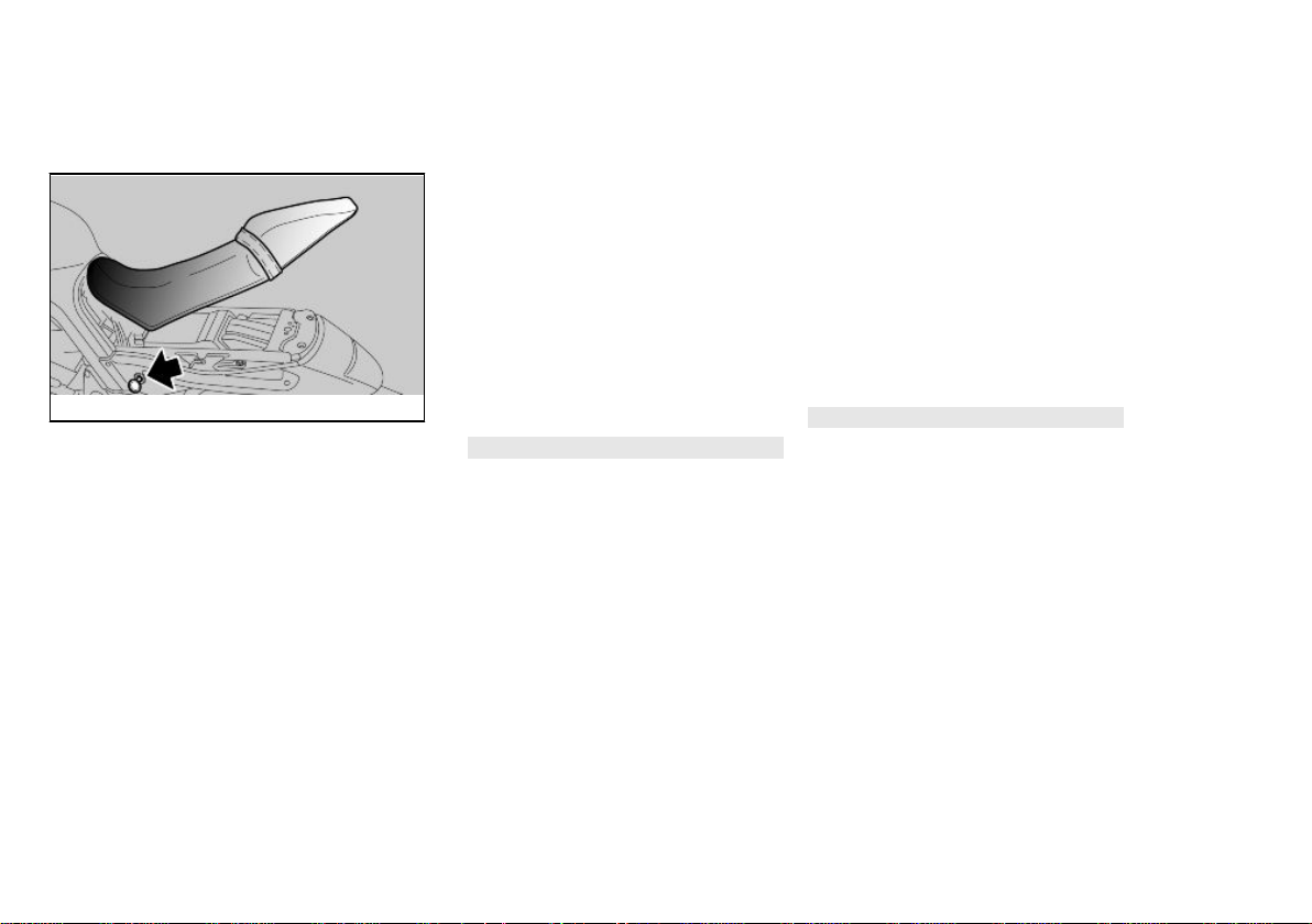
Abertura sillín (02_27, 02_28)
•
Colocar el vehículo sobre el caballete.
•
Introducir la llave en la cerradura del asiento.
•
Girar la llave en sentido horario
presionando levemente el centro de la parte posterior del
asiento para poder desenganchar el perno, levantar y luego
extraer el asiento.
ATENCIÓN
ANTES DE BAJAR Y BLOQUEAR EL
ASIENTO, CONTROLAR DE NO HABER OLVIDADO LA LLAVE EN LOS
COMPARTIMIENTOS PORTADOCUMENTOS/KIT HERRAMIENTAS.
Opening the saddle (02_27,
02_28)
•
Rest the vehicle on its stand.
•
Insert the key in the saddle lock.
•
Turn the key clockwise by
pressing slightly the centre of
the saddle rear part so that the
hook is easily released; lift and
slide off the saddle backwards.
CAUTION
BEFORE LOWERING AND LOCKING
THE SADDLE, CHECK THAT THE KEY
HAS NOT BEEN LEFT IN THE GLOVEBOX / TOOL KIT COMPARTMENT.
45

02_28
Para bloquear el asiento:
•
Colocar la parte delantera del
asiento en su alojamiento.
•
Bajar la parte trasera y colocar
el asiento de manera que los
dos enganches de fijación queden correctamente enganchados a los orificios del chasis.
•
Presionar en el centro de la parte trasera del asiento, haciendo
calzar la cerradura.
ANTES DE CONDUCIR ASEGURARSE
DE QUE EL ASIENTO ESTÉ CORRECTAMENTE BLOQUEADO.
To lock the saddle:
•
Place the saddle front part in its
position.
•
Lower the rear part and position
the saddle so that the retaining
hooks are properly hooked to
the eyelets on the chassis.
•
Press the centre of the saddle
rear part to trip the lock.
BEFORE RIDING, MAKE SURE THAT
THE SADDLE IS CORRECTLY
LOCKED.
02_29
Compartimiento porta-doc./kit
herramientas (02_29)
•
Extraer el asiento.
•
Quitar la tapa.
46
Glove/tool kit compartment
(02_29)
•
Remove the saddle.
•
Remove the cover.

2 Vehìculo / 2 Vehicle
La identificación (02_30,
02_31)
Es conveniente tomar nota de los números del chasis y del motor, en el espacio
reservado para los mismos en el presente manual. El número de chasis puede
ser útil para adquirir piezas de repuesto.
ATENCIÓN
Identification (02_30, 02_31)
Write down the chassis and engine number in the specific space of this manual.
The chassis number is handy when purchasing spare parts.
CAUTION
02_30
02_31
ALTERING IDENTIFICATION NUMBERS IS AN OFFENCE WHICH MAY
LA ALTERACIÓN DE LOS NÚMEROS
DE IDENTIFICACIÓN PUEDE ACARREAR GRAVES SANCIONES PENALES Y ADMINISTRATIVAS. EN PARTICULAR, LA ALTERACIÓN DEL NÚMERO DE CHASIS IMPLICA LA INMEDIATA CADUCIDAD DE LA GARANTÍA
NÚMERO DE CHASIS
El número de chasis está estampillado
en el manguito de dirección, lado derecho.
Chasis Nº....................
NÚMERO DE MOTOR ENGINE NUMBER
47
RESULT IN SEVERE CRIMINAL
CHARGES AND FINES. PARTICULARLY MODIFYING THE CHASSIS NUMBER WILL IMMEDIATELY INVALIDATE THE WARRANTY.
CHASSIS NUMBER
The chassis number is stamped on the
right side of the headstock.
Chassis No. ....................

El número de motor está estampillado en
la bancada del cárter motor lado izquierdo.
Motor Nº....................
The engine number is printed on the base
of the left side engine crankcase.
Engine No. ....................
02_32
Fijación maletero (02_32)
Sobre la parte trasera del asiento se puede fijar un pequeño equipaje, ajustándolo
con los elásticos, que se fijarán en los 4
enganches (2 para cada lado).
Peso máximo permitido: 5 kg (11 lb).
ATENCIÓN
EL EQUIPAJE DEBE SER DE DIMEN-
SIONES REDUCIDAS Y ESTAR SUJETADO FIRMEMENTE.
Luggage anchor point (02_32)
A small piece of luggage can be fastened
on the rear part of the saddle using the
elastic straps that are secured to the 4
anchoring hooks (2 per side).
Maximum weight allowed: 5 kg (11 lb)
CAUTION
CARRY ONLY LUGGAGE WITH ADE-
QUATE DIMENSIONS AND SECURE IT
FIRMLY.
48

Griso 8V-1200
Cap. 03
El uso
Chap. 03
Use
49

Controles (03_01)
Checks (03_01)
ATENCIÓN
ANTES DE LA PARTIDA, REALIZAR
SIEMPRE UN CONTROL PRELIMINAR
DEL VEHÍCULO PARA OBTENER UNA
CORRECTA Y SEGURA FUNCIONALIDAD. EL HECHO DE NO REALIZAR
DICHAS OPERACIONES PUEDE CAUSAR GRAVES LESIONES PERSONALES O DAÑOS GRAVES AL VEHÍCULO. SI NO SE COMPRENDE EL
FUNCIONAMIENTO DE ALGÚN MANDO O EN EL CASO DE QUE SE DETECTE O SE SOSPECHE DE ALGUNA
ANOMALÍA DE FUNCIONAMIENTO,
DIRIGIRSE A UN CONCESIONARIO
OFICIAL Moto Guzzi. EL TIEMPO NECESARIO PARA UN CONTROL ES
MUY BREVE Y RESULTA MUY VENTAJOSO PARA LA SEGURIDAD.
Este vehículo está preparado para identificar, en tiempo real, eventuales anomalías de funcionamiento, memorizadas
por la centralita electrónica.
Cada vez que el conmutador de arranque
se posiciona en "ON", en el tablero se
enciende, durante aproximadamente
tres segundos, el testigo LED alarma.
CAUTION
BEFORE SETTING-OFF, ALWAYS
CARRY OUT A PRELIMINARY CHECK
OF THE VEHICLE, FOR CORRECT
AND SAFE OPERATION. FAILURE TO
DO SO MAY LEAD TO SEVERE INJURY OR VEHICLE DAMAGE. DO NOT
HESITATE TO CONTACT AN Official
Moto Guzzi Dealer IF YOU DO NOT UNDERSTAND HOW SOME CONTROLS
WORK OR IF MALFUNCTIONING IS
DETECTED OR SUSPECTED.
CHECKS DO NOT TAKE LONG AND
RESULT IN SIGNIFICANTLY ENHANCED SAFETY.
This vehicle has been programmed to indicate in real time any operation failure
stored in the electronic control unit memory.
Every time the ignition switch is turned to
"KEY ON", the alarm LED warning light
turns on for about three seconds on the
instrument panel.
03_01
50

CONTROLES PRELIMINARES
3 El uso / 3 Use
Freno de disco delantero y trasero Controlar el funcionamiento, la
Acelerador Controlar que funcione con
Aceite motor Controlar y/o restaurar el nivel si es
Ruedas/neumáticos Controlar el estado superficial de
Palancas del freno Controlar que funcionen con
carrera en vacío de las palancas
de mando, el nivel del líquido y
eventuales pérdidas. Controlar el
desgaste de las pastillas. Si es
necesario efectuar el llenado del
líquido de frenos.
suavidad y que se pueda abrir y
cerrar completamente, en todas
las posiciones de la dirección.
Regular y/o lubricar si es
necesario.
necesario.
los neumáticos, la presión de
inflado, el desgaste y eventuales
daños.
Quitar eventuales cuerpos
extraños encastrados en las
esculturas de la banda de
rodadura.
suavidad.
Lubricar las articulaciones y
regular la carrera si es necesario.
PRE-RIDE CHECKS
Front and rear disc brake Check for proper operation. Check
brake lever empty travel and brake
fluid level. Check for leaks. Check
brake pads for wear. If necessary
top-up with brake fluid.
Throttle grip Check that the throttle functions
smoothly and can be fully opened
and closed in all steering positions.
Adjust and/or lubricate if
necessary.
Engine oil Check and/or top-up as required.
Wheels/tyres Check that tyres are in good
conditions. Check inflation
pressure, tyre wear and potential
damage.
Remove any foreign objects stuck
in the tread.
Brake levers Check they function smoothly.
Lubricate the joints and adjust the
travel, if necessary.
Clutch Check for proper operation. Check
clutch lever free play and fluid
level. Check for leaks. Top-up the
fluid if necessary; the clutch must
work without gripping and/or
sliding.
51

Embrague Controlar el funcionamiento, la
carrera en vacío de la palanca de
mando, el nivel del líquido y
eventuales pérdidas. Si es
necesario, efectuar el llenado del
líquido: el embrague debe
funcionar sin tironeos ni
deslizamientos.
Dirección Controlar que la rotación sea
homogénea, fácilmente deslizable
y sin juego ni aflojamientos.
Caballete central - lateral Controlar que funcione. Controlar
que durante el descenso y el
ascenso del caballete no haya
fricciones y que la tensión de los
muelles lo regrese a su posición
normal. Lubricar los
acoplamientos y las articulaciones
si es necesario. Controlar el
correcto funcionamiento del
interruptor de seguridad.
Elementos de fijación Controlar que los elementos de
fijación no se estén flojos.
Eventualmente, regular o apretar.
Depósito combustible Controlar el nivel y reabastecer si
es necesario.
Controlar las eventuales pérdidas
u oclusiones del circuito.
Steering Check that the rotation is
Centre - side stand Check it works properly. Check
Clamps Check that the clamping elements
Fuel tank Check the coolant level and refill if
Engine stop switch (ON - OFF) Check function.
Lights, warning lights, horn, rear
stop light switch and electrical
devices
Transmission oil - Guzzi Check. Should top-up be
homogeneous, smooth and there
are no signs of clearance or
slackness.
that there is no resistance when the
side stand is pulled up and down
and that the spring tension makes
it snap back to its rest position.
Lubricate couplings and joints if
necessary. Check the safety
switch for correct operation.
are not loose.
Adjust or tighten them as required.
necessary.
Check the circuit for potential leaks
or obstructions.
Check that the tank cover closes
correctly.
Check the correct operation of the
horn and lights. Replace the bulbs
or repair any malfunction.
necessary, please refer to an
52

3 El uso / 3 Use
Interruptor de parada del motor
(ON - OFF)
Controlar que el tapón del
combustible esté correctamente
cerrado.
Controlar el funcionamiento
correcto.
authorised Moto Guzzi repair
shop.
Luces, testigos, avisador sonoro,
interruptores luz de stop trasera y
dispositivos eléctricos
Aceite de transmisión - Guzzi Controlar. Si fuera necesario
Controlar el funcionamiento
correcto de los dispositivos
sonoros y visuales. Sustituir las
bombillas o intervenir en caso de
avería.
realizar el llenado, dirigirse a un
taller autorizado Moto Guzzi.
Abastecimiento (03_02)
Para reabastecer el combustible:
•
Levantar la tapa (1).
•
Introducir la llave (2) en la cerradura de la tapa del depósito
(3).
•
Girar la llave en sentido horario,
tirar de la portezuela del combustible y abrirla.
03_02
•
Reabastecer.
Refuelling (03_02)
To refuel:
•
Lift the cover (1).
•
Introduce the key (2) in the fuel
tank cap lock (3).
•
Turn the key clockwise, pull and
open the fuel tank lid.
•
Refuel.
CAUTION
DO NOT ADD ADDITIVES OR ANY
OTHER SUBSTANCES TO THE FUEL.
When using a funnel or any other element, make sure it is perfectly clean.
53

ATENCIÓN
NO AGREGAR ADITIVOS U OTRAS
SUSTANCIAS AL COMBUSTIBLE.
SI SE USA UN EMBUDO U OTRO OBJETO, ASEGURARSE DE QUE ESTÉ
PERFECTAMENTE LIMPIO.
NO LLENAR EL DEPÓSITO COMPLETAMENTE; EL NIVEL MÁXIMO DE
COMBUSTIBLE DEBE QUEDAR POR
DEBAJO DEL BORDE INFERIOR DEL
COLECTOR (VER FIGURA).
Características Técnicas
Combustible (incluido reserva)
16,4 l (4.33 Uk gal)
Reserva de combustible
3.3 l (0.87 gal)
efectuado el reabastecimiento:
•
El cierre de la tapa es posible
sólo introduciendo la llave (2).
•
Con la llave (2) introducida, cerrar la tapa, presionándola.
•
Extraer la llave (2).
•
Volver a cerrar la tapa (1).
DO NOT FILL THE TANK UP TO THE
RIM; FUEL MAXIMUM LEVEL MUST
ALWAYS BE BELOW THE LOWER
EDGE OF THE FILLER NECK (SEE
FIGURE).
Characteristic
Fuel (reserve included)
16.4 l (4.33 Uk gal)
Fuel reserve
3.3 l (0.87 gal)
after refuelling:
•
The cap can only be closed if the
key (2) is inserted.
•
Once the key (2) is inserted,
press to close the cap again.
•
Remove the key (2).
•
Close the cover (1) again.
54

3 El uso / 3 Use
ASEGURARSE DE QUE LA TAPA ESTÉ CORRECTAMENTE CERRADA.
MAKE SURE THE CAP IS TIGHTLY
CLOSED.
03_03
03_04
Regulación amortiguadores
traseros (03_03, 03_04, 03_05)
La suspensión trasera esta compuesta
por el grupo muelle-amortiguador, que se
conecta mediante silent-block, al chasis
y por medio de articulaciones de levas, a
la horquilla trasera.
Para regular el ajuste del vehículo, el
amortiguador consta de:
- un dispositivo de ajuste roscado (1) para regular el frenado hidráulico en extensión;
- un tornillo de regulación (2) para regular
el frenado hidráulico en compresión;
- una tuerca (3) para regular la precarga
del muelle y una tuerca de bloqueo (4).
La programación estándar del amortiguador trasero ha sido previsto para satisfacer la mayoría de las condiciones de
Rear shock absorbers
adjustment (03_03, 03_04,
03_05)
The rear suspension consists of a springshock absorber unit linked to the frame
via silent-block and to the rear fork via a
linkage system.
To set the vehicle suspension, the shock
absorber has:
- a set screw (1) to adjust the hydraulic
rebound damping;
- a set screw (2) to adjust the hydraulic
compression damping;
- a ring nut (3) to adjust the spring preloading and a locking ring nut (4).
Standard rear shock absorber setting is
adjusted to suit most high and low speed
55

conducción a velocidad moderada o elevada, para el transporte del conductor
con equipaje.
Sin embargo es posible personalizar la
regulación en función del uso del vehículo.
ANTES DE OPERAR EN LOS DISPOSITIVOS DE AJUSTE, ESPERAR QUE
EL MOTOR Y EL TUBO DE ESCAPE SE
HAYAN ENFRIADO COMPLETAMENTE.
NOTA
PARA CONTAR EL NÚMERO DE NI-
VELES Y/O GIROS DE LOS REGULADORES DE AJUSTE (1-2) SIEMPRE SE
DEBE PARTIR DE LA POSICIÓN MÁS
RÍGIDA (ROTACIÓN COMPLETA DEL
REGULADOR EN SENTIDO HORARIO).
COMO REFERENCIA PARA REGULAR EL FRENADO HIDRÁULICO EN
COMPRESIÓN Y EXTENSIÓN, UTILIZAR LOS REGULADORES DE AJUSTE (1-2).
GIRAR GRADUALMENTE LOS REGULADORES DE AJUSTE (1-2), UNA
MARCA CADA VEZ.
riding conditions, to transport the rider
plus luggage.
However, this set can be modified for
specific needs according to vehicle use.
ALLOW ENGINE AND EXHAUST SILENCER TO COOL OFF BEFORE OPERATING THE SET SCREWS.
NOTE
TO COUNT THE NUMBER OF CLICKS
AND/OR TURNS OF SET SCREWS
(1-2) ALWAYS START FROM THE
MOST RIGID SETTING (SET SCREW
FULLY CLOCKWISE).
AS REFERENCE TO ADJUST HYDRAULIC COMPRESSION DAMPING
AND EXTENSION, USE SET SCREWS
(1-2).
TURN THE SET SCREW SLOWLY
(1-2), ONE NOTCH AT A TIME.
56

3 El uso / 3 Use
03_05
•
Utilizando la llave apropiada disponible en los Concesionarios
oficiales Moto Guzzi, desenroscar la tuerca de bloqueo (4).
•
Accionar la tuerca de regulación
(3) para regular la precarga del
muelle (A).
•
Efectuada la regulación, apretar
la tuerca de bloqueo (4).
•
Intervenir en el tornillo (1) para
regular el frenado hidráulico en
extensión del amortiguador.
•
Accionar el tornillo (2) para regular el frenado hidráulico en
compresión del amortiguador.
ATENCIÓN
REGULAR LA PRECARGA DEL MUE-
LLE Y EL FRENADO HIDRÁULICO EN
EXTENSIÓN DEL AMORTIGUADOR
SEGÚN LAS CONDICIONES DE USO
DEL VEHÍCULO. AUMENTANDO LA
PRECARGA DEL MUELLE, TAMBIÉN
SE DEBE AUMENTAR EL FRENADO
HIDRÁULICO EN EXTENSIÓN DEL
AMORTIGUADOR, PARA EVITAR IMPROVISOS REBOTES DURANTE LA
CONDUCCIÓN. EN ESTE CASO DIRIGIRSE A UN CONCESIONARIO OFICIAL Moto Guzzi. PROBAR REPETIDAMENTE EL VEHÍCULO EN CARRETERA HASTA OBTENER LA REGULACIÓN OPTIMA.
•
Using the specific spanner available at any Moto Guzzi Official
Dealer, unscrew the locking ring
nut (4).
•
Operate on the set ring nut (3) to
adjust the spring (A) preloading.
•
Once the adjustment is done,
screw the locking ring nut (4).
•
Turn the (1) screw to adjust the
shock absorber hydraulic rebound damping.
•
Turn the screw (2) to adjust the
shock absorber hydraulic compression damping.
CAUTION
SET THE SPRING PRELOADING AND
THE REBOUND DAMPING OF THE
SHOCK ABSORBERS ACCORDING
TO THE VEHICLE USE CONDITIONS.
IF THE SPRING PRELOADING IS INCREASED, IT IS NECESSARY TO INCREASE THE REBOUND DAMPING
ACCORDINGLY TO AVOID SUDDEN
JERKS WHEN RIDING. IF NECESSARY, CONTACT AN OFFICIAL Moto
Guzzi DEALER. TRY RIDING THE VEHICLE ON THE STREET UNTIL THE
OPTIMUM ADJUSTMENT IS OBTAINED.
57

REGULACIÓN DEL AMORTIGUADOR
Longitud muelle (precargado) (A) 161 mm. (6.34 in)
Regulación en extensión, virola (1) de todo cerrado (*) abrir (**) 17
pasos
SHOCK ABSORBER ADJUSTMENT
Length of (preloaded) spring (A) 161 mm (6.34 in)
Rebound adjustment, ring nut (1) open (**) 17 clicks from fully closed
(*)
Regulación en compresión, tornillo
(2)
de todo cerrado (*) abrir (**) 1,5
pasos
(*) = en sentido horario
(**) = sentido antihorario
Regulación horquilla
delantera (03_06, 03_07,
03_08)
Con la palanca del freno delantero accionada, presionar repetidamente en el manillar, empujando a fondo la horquilla. La
carrera debe ser suave y los vástagos no
deben evidenciar marcas de aceite.
03_06
Controlar el ajuste de todos los órganos
y el funcionamiento de las articulaciones
de la suspensión delantera y trasera.
Compression adjustment, screw
(2)
(*) = clockwise
(**) = anticlockwise
Front fork adjustment (03_06,
03_07, 03_08)
Operating the front brake lever, press the
handlebar repeatedly to send the fork
fully down. The stroke should be soft and
there should be no oil marks on the
stems.
Check the tightening of all the elements
and the correct operation of the front and
rear suspension joints.
open (**) 1,5 click from fully closed
(*)
58

3 El uso / 3 Use
03_07
03_08
La configuración estándar de la horquilla
delantera está regulada para satisfacer
la mayoría de las condiciones de conducción a baja y a alta velocidad, con el
vehículo parcialmente cargado o a plena
carga.
Sin embargo, es posible efectuar una regulación personalizada en función del
uso del vehículo.
ATENCIÓN
LAS REGULACIONES PARA USO DE-
PORTIVO SE DEBEN REALIZAR EXCLUSIVAMENTE EN OCASIÓN DE
COMPETENCIAS ORGANIZADAS O
EVENTOS DEPORTIVOS, SIEMPRE
QUE SE REALICEN EN CIRCUITOS
AISLADOS DE LA CIRCULACIÓN DE
CARRETERA Y CON LA APROBACIÓN DE LAS AUTORIDADES COMPETENTES.
ESTÁ ESTRICTAMENTE PROHIBIDO
REALIZAR REGULACIONES PARA
USO DEPORTIVO Y CONDUCIR EL
VEHÍCULO CON DICHO AJUSTE EN
CARRETERAS Y AUTOPISTAS.
PARA LA REGULACIÓN, PARTIR
SIEMPRE DE LA POSICIÓN MÁS RÍGIDA (ROTACIÓN COMPLETA DE LOS
REGULADORES (1 - 2) EN SENTIDO
HORARIO). COMO REFERENCIA PARA REGULAR EL FRENADO HIDRÁULICO EN COMPRESIÓN Y EXTEN-
The standard front fork setting is adjusted
to suit most low and high speed riding
conditions, whether the vehicle is partially or fully loaded.
This setting can also be customised
based on vehicle use.
CAUTION
SPORTS SETTING MAY BE USED ON-
LY FOR OFFICIAL COMPETITIONS TO
BE CARRIED OUT ON TRACKS,
AWAY FROM NORMAL ROAD TRAFFIC AND WITH THE AUTHORISATION
OF THE RELEVANT AUTHORITIES.
IT IS STRICTLY FORBIDDEN TO USE
SPORT SETTINGS AND RIDE THE VEHICLE SO SET ON ROADS AND MOTORWAYS.
FOR ADJUSTMENT, ALWAYS START
FROM THE MOST RIGID SETTING
(SET SCREWS (1 - 2) FULLY CLOCKWISE). USE THE NOTCHES ON SET
SCREWS (1 - 2) AS REFERENCES TO
ADJUST HYDRAULIC COMPRESSION
AND REBOUND DAMPING.
TURN THE SET SCREWS (1 - 2) GRADUALLY BY 1/8 OF A TURN AT A TIME.
59

SIÓN, UTILIZAR LAS MARCAS DE
LOS REGULADORES DE AJUSTE (1 -
2).
GIRAR GRADUALMENTE LOS REGU-
LADORES DE AJUSTE (1 - 2) 1/8 DE
VUELTA CADA VEZ.
REGULACIÓN HORQUILLA DELANTERA
Regulación hidráulica estándar en
extensión, tornillo (1)
Regulación hidráulica para uso
deportivo en extensión, tornillo (1)
Regulación hidráulica estándar en
compresión, tornillo (2)
Regulación hidráulica para uso
deportivo en compresión, tornillo
(2)
Precarga del muelle, tuerca (3) De todo cerrado (*) abrir (**) 4 - 5
Saliente vástagos (A) de placa
superior (excluido el tapón)
(regulación estándar)
de todo cerrado (*) abrir (**) 1,5
pasos
De todo cerrado (*) abrir (**) 0,5 1 vuelta
de todo cerrado (*) abrir (**) 1 paso
Desde la posición completamente
cerrado (*), abrir (**) 0,5 - 1 vuelta
marcas de saliente
4 muescas de resalte
Para este tipo de regulación,
dirigirse únicamente a un
Concesionario Oficial Moto Guzzi
FRONT FORK ADJUSTMENT
Standard rebound damping
adjustment, screw (1)
Hydraulic rebound damping
adjustment for sports use, screw
(1)
Standard compression damping
adjustment, screw (2)
Hydraulic compression damping
adjustment for sports use, screw
(2)
Spring preloading, nut (3) Open (**) 4 - 5 protrusion notches
Stems (A) protrusion from top plate
(excluding cover) (standard
adjustment)
60
open (**) 1,5 click from fully closed
(*)
Open (**) 0.5 - 1 turn from fully
closed (*)
open (**) 1 click with fully closed (*)
Open (**) 0.5 - 1 turn from fully
closed (*)
from fully closed (*)
4 protrusion notches
Take your vehicle only to a Moto
Guzzi Official Dealer for this type
of adjustment.

Saliente vástagos (A) de placa
3 El uso / 3 Use
superior (excluido el tapón)
(regulación para uso deportivo)
5 muescas de resalte
Para este tipo de regulación,
dirigirse únicamente a un
Concesionario Oficial Moto Guzzi
Stems (A) protrusion from top plate
(excluding cover) (sports use
adjustment)
5 protrusion notches
Take your vehicle only to a Moto
Guzzi Official Dealer for this type
of adjustment.
03_09
(*) = en sentido horario
(**) = sentido antihorario
Regulación leva freno
delantero (03_09)
Se puede regular la distancia entre los
extremos de la palanca y el puño, girando
el dispositivo.
Las posiciones "1" y "4" corresponden a
una distancia aproximada, entre el extremo de la palanca y el puño, de 105 y 85
mm (4.1 y 3.3 in) respectivamente.
Las posiciones "2" y "3" corresponden a
distancias intermedias.
Para la regulación: empujar la palanca de
mando hacia adelante y girar el dispositivo hasta que el valor deseado se corresponda con la flecha de comprobación.
(*) = clockwise
(**) = anticlockwise
Justering af greb til forbremse
(03_09)
Adjust the distance between the lever
end and the hand grip by turning the set
screw.
Positions "1" and "4" correspond to a lever end-hand grip distance of about 105
and 85 mm (4.1 - 3.3 in) respectively.
Positions "2" and "3" correspond to intermediate distances.
To adjust: push the control lever forward
and turn the set screw until the arrow
points at the desired number.
61

Regulación leva embrague
(03_10)
Clutch lever adjustment
(03_10)
03_10
Se puede regular la distancia entre los
extremos de la palanca y el puño, girando
el dispositivo.
Las posiciones "1" y "4" corresponden a
una distancia aproximada, entre el extremo de la palanca y el puño, de 105 y 85
mm (4.1 y 3.3 in) respectivamente.
Las posiciones "2" y "3" corresponden a
distancias intermedias.
Para la regulación: empujar la palanca de
mando hacia adelante y girar el dispositivo hasta que el valor deseado se corresponda con la flecha de comprobación.
Rodaje
El rodaje del motor es fundamental para
garantizar su duración y su correcto funcionamiento. Recorrer, en lo posible, carreteras con muchas curvas y/o con
colinas, donde el motor, las suspensiones y los frenos sean sometidos a un
rodaje más eficaz. Variar la velocidad de
conducción durante el rodaje. De esta
manera, se permite "recargar" el trabajo
de los componentes y luego "aliviarlo",
enfriando las partes del motor.
Adjust the distance between the lever
end and the hand grip by turning the set
screw.
Positions "1" and "4" correspond to a lever end-hand grip distance of about 105
and 85 mm (4.1 - 3.3 in) respectively.
Positions "2" and "3" correspond to intermediate distances.
To adjust: push the control lever forward
and turn the set screw until the arrow
points at the desired number.
Running in
Engine run-in is essential to ensure engine long life and correct operation.
Twisty roads and gradients are ideal to
run in engine, brakes and suspensions
effectively. Vary your riding speed during
the run-in. In this way, you allow for the
work of components to be "loaded" and
then "unloaded", thus cooling the engine
parts.
CAUTION
THE CLUTCH MAY EMIT A SLIGHT
BURNING SMELL WHEN FIRST USED.
62

3 El uso / 3 Use
ATENCIÓN
ES POSIBLE QUE DEL EMBRAGUE
SE DESPRENDA UN LEVE OLOR DE
QUEMADO, DURANTE EL PRIMER
PERIODO DE USO. ESTE FENÓMENO
ES PERFECTAMENTE NORMAL Y DESAPARECERÁ APENAS EL DISCO
DEL EMBRAGUE TENGA UN POCO
DE USO.
SI BIEN ES IMPORTANTE FORZAR
LOS COMPONENTES DEL MOTOR
DURANTE EL RODAJE, PRESTAR
MUCHA ATENCIÓN PARA NO EXCEDERSE.
ATENCIÓN
SÓLO DESPUÉS DE HABER EFEC-
TUADO EL CONTROL PERIÓDICO DE
FINALIZACIÓN DEL RODAJE ES POSIBLE OBTENER LAS MEJORES
PRESTACIONES DEL VEHÍCULO.
THIS OCCURRENCE IS PERFECTLY
NORMAL AND IT WILL DISAPPEAR
ONCE THE CLUTCH DISC HAS BEEN
BROKEN IN.
IT IS IMPORTANT TO STRAIN ENGINE
COMPONENTS DURING RUN-IN,
HOWEVER, MAKE SURE NOT TO
OVERDO THIS.
CAUTION
ONLY AFTER THE SERVICE AT THE
END OF THE RUN-IN PERIOD CAN
THE BEST PERFORMANCE OF YOUR
VEHICLE BE OBTAINED.
Atenerse a las siguientes indicaciones:
•
No acelerar repentina y completamente cuando el motor está
en marcha con un bajo régimen
de revoluciones, tanto durante
como después del rodaje.
•
Durante los primeros 100 km
(62 mi), accionar con prudencia
los frenos para evitar frenadas
bruscas y prolongadas. Esto
permite un correcto ajuste del
63
Follow the guidelines detailed below:
•
Do not twist the throttle grip
abruptly and completely when
the engine is working at a low
revs, either during or after runin.
•
During the first 100 km (62
miles) operate the brakes with
caution avoid rough and long
braking. That is to permit the adequate adjustment of the pad
friction material to the brake
discs.

material de fricción de las pastillas en los discos del freno.
AL ALCANZAR EL KILOMETRAJE
PREVISTO, DIRIGIRSE A UN CONCESIONARIO OFICIAL Moto Guzzi PARA
QUE EJECUTE LOS CONTROLES
CONTEMPLADOS EN LA TABLA "FIN
DEL RODAJE" DE LA SECCIÓN MANTENIMIENTO PROGRAMADO, CON
LA FINALIDAD DE EVITAR DAÑOS A
LAS PERSONAS O AL VEHÍCULO.
AFTER THE SPECIFIED MILEAGE,
TAKE THE VEHICLE TO AN OFFICIAL
Moto Guzzi DEALER FOR THE
CHECKS INDICATED IN THE "AFTER
RUN-IN" TABLE IN THE SCHEDULED
MAINTENANCE SECTION TO AVOID
INJURING YOURSELF, OTHERS AND /
OR DAMAGING THE VEHICLE.
Arranque dificultoso
El vehículo está provisto de estárter automático y no requiere ninguna advertencia para el arranque en frío.
En caso de temperatura ambiente baja
(cercana o inferior a 0°C / 32°F) el estárter automático entra en funcionamiento
aumentando el número de revoluciones
hasta alcanzar la temperatura óptima del
motor y se desconecta luego automáticamente.
NOTA
EL ESTÁRTER AUTOMÁTICO NO
PUEDE ACCIONARSE MANUALMENTE.
64
Difficult start up
The vehicle has an automatic starter and
does not require any special instruction
for cold start.
If the ambient temperature is low (near or
below 0°C / 32°F) the automatic starter
activates, increasing the number of revs
until the ideal engine temperature is
reached and disconnects itself automatically.
NOTE
THE AUTOMATIC STARTER CANNOT
BE ACTIVATED MANUALLY.

Aparcamiento
3 El uso / 3 Use
Parking
La elección de la zona de aparcamiento
es muy importante y se deben respetar la
señalización vial y las indicaciones que
se presentan a continuación.
ATENCIÓN
APARCAR EL VEHÍCULO SOBRE UN
TERRENO SÓLIDO Y PLANO PARA
EVITAR QUE SE CAIGA.
NO APOYAR EL VEHÍCULO EN LAS
PAREDES Y NO ACOSTARLO EN EL
PAVIMENTO.
ASEGURARSE DE QUE EL VEHÍCULO, Y ESPECIALMENTE LAS PARTES
CALIENTES DEL MISMO, NO REPRESENTEN PELIGRO ALGUNO PARA
LAS PERSONAS Y LOS NIÑOS. NO
DEJAR EL VEHÍCULO SIN VIGILANCIA, CON EL MOTOR ENCENDIDO O
CON LA LLAVE COLOCADA EN EL
CONMUTADOR DE ARRANQUE.
ATENCIÓN
LA CAÍDA O LA EXCESIVA INCLINA-
CIÓN DEL VEHÍCULO PUEDEN PRODUCIR DERRAMES DE COMBUSTIBLE.
EL COMBUSTIBLE UTILIZADO PARA
LA PROPULSIÓN DE LOS MOTORES
DE EXPLOSIÓN ES EXTREMADAMENTE INFLAMABLE Y PUEDE RESULTAR EXPLOSIVO EN DETERMINADAS CONDICIONES.
It is very important to select an adequate
parking spot, in compliance with road signals and the guidelines described below.
CAUTION
PARK ON SAFE AND LEVEL GROUND
TO PREVENT THE VEHICLE FROM
FALLING.
DO NOT LEAN THE vehicle ON A
WALL OR LAY IT ON THE GROUND.
MAKE SURE THE VEHICLE AND SPECIALLY ITS HOT PARTS DO NOT
POSE ANY RISK TO PEOPLE OR
CHILDREN. DO NOT LEAVE YOUR VEHICLE UNATTENDED WITH THE ENGINE ON OR THE KEY IN THE IGNITION SWITCH.
CAUTION
VEHICLE FALL OR EXCESSIVE INCLI-
NATION CAN CAUSE FUEL OUTFLOW.
FUEL USED TO DRIVE EXPLOSION
ENGINES IS HIGHLY FLAMMABLE
AND CAN BECOME EXPLOSIVE UNDER SPECIFIC CONDITIONS.
DO NOT REST THE RIDER OR PASSENGER WEIGHT ON THE SIDE
STAND.
65

NO CARGAR SOBRE EL CABALLETE
LATERAL EL PESO DEL CONDUCTOR NI EL DEL PASAJERO.
Escape catalítico
El vehículo cuenta con un silenciador con
catalizador metálico del tipo "trivalente al
platino - paladio - rodio".
Dicho dispositivo tiene la función de oxidar el CO (monóxido de carbono) y los
HC (hidrocarburos incombustos) presentes en los gases de escape, convirtiéndolos respectivamente en anhídrido carbónico y vapor de agua.
EVITAR DE APARCAR EL VEHÍCULO
CERCA DE ARBUSTOS SECOS O EN
LUGARES ACCESIBLES PARA LOS
NIÑOS DADO QUE EL SILENCIADOR
DEL ESCAPE, DURANTE EL USO, ALCANZA TEMPERATURAS MUY ELEVADAS; POR LO TANTO PRESTAR LA
MÁXIMA ATENCIÓN Y EVITAR TODO
TIPO DE CONTACTO ANTES DE QUE
SE HAYA ENFRIADO COMPLETAMENTE.
66
Catalytic silencer
The vehicle has a silencer with a "platinum - palladium - rhodium three-way"
metal catalytic converter.
This device oxidises the CO (carbon
monoxide) and the HC (unburned hydrocarbons) in the exhaust gas, producing
carbon dioxide and water vapour respectively.
DO NOT PARK THE VEHICLE NEAR
DRY BRUSHWOOD OR IN PLACES
EASILY ACCESSIBLE BY CHILDREN
BECAUSE THE CATALYTIC CONVERTER REACHES HIGH TEMPERATURES DURING VEHICLE OPERATION; FOR THIS REASON, PAY
UTMOST ATTENTION AND DO NOT
TOUCH IT UNTIL IT HAS COMPLETELY COOLED DOWN.

3 El uso / 3 Use
NO UTILIZAR GASOLINA CON PLOMO DADO QUE PROVOCA LA DESTRUCCIÓN DEL CATALIZADOR.
DO NOT USE LEADED PETROL AS IT
CAUSES IRREPARABLE DAMAGE TO
THE CATALYTIC CONVERTER.
Se advierte al propietario del vehículo
que la ley puede prohibir lo siguiente:
•
la eliminación de cualquier dispositivo o elemento incorporado
a un vehículo nuevo, con el fin
de controlar la emisión de ruidos, antes de la venta o entrega
del vehículo al comprador final o
mientras se lo está utilizando, o
cualquier otro acto tendiente a
inutilizarlo, por parte de cualquiera, salvo por intervenciones
de mantenimiento, reparación o
sustitución;
•
el uso del vehículo después de
que dicho dispositivo o elemento constitutivo haya sido extraído o inutilizado.
Controlar el silenciador/tubo de escape y
los tubos del escape, comprobando que
no existan indicios de herrumbre u orificios y que el sistema de escape funcione
correctamente.
Si el ruido producido por el sistema de
escape aumenta, contactar inmediatamente con un CONCESIONARIO o un
Taller autorizado Moto Guzzi.
Vehicle owners are warned that the law
may prohibit the following:
•
the removal of any device or element belonging to a new vehicle or any other action by anyone leading to render it nonoperating, if not for maintenance, repair or replacement
reasons, in order to control
noise emission before the sale
or delivery of the vehicle to the
ultimate buyer or while it is used;
•
using the vehicle after that device or element has been removed or rendered non-operating.
Check the muffler/exhaust silencer and
the silencer pipes, make sure there are
no signs of rust or holes and that the exhaust system works properly.
If the noise produced by the exhaust system increases, get immediately in touch
with the Dealer or with a Moto Guzzi authorised repair shop.
NOTE
DO NOT TAMPER WITH THE EX-
HAUST SYSTEM.
67

NOTA
ESTÁ PROHIBIDO ALTERAR EL SIS-
TEMA DE ESCAPE.
03_11
Soporte (03_11, 03_12)
EL CABALLETE LATERAL Y EL CENTRAL DEBEN GIRAR LIBREMENTE,
EN CASO DE SER NECESARIO ENGRASAR LA ARTICULACIÓN.
CABALLETE LATERAL
En el caso de que alguna maniobra (por
ejemplo: el desplazamiento del vehículo)
haya provocado el retroceso del caballete,se debe proceder como se indica a
continuación para volver a poner el vehículo sobre el mismo:
•
Tomar el puño izquierdo y apoyar la mano derecha sobre la
parte trasera superior del vehículo.
•
Empujar el caballete lateral con
el pie derecho, extendiéndolo
completamente.
•
Inclinar el vehículo hasta que el
caballete se apoye en el suelo.
Girar el manillar completamente
hacia la izquierda
Stand (03_11, 03_12)
THE SIDE AND CENTRE STANDS
SHOULD TURN SMOOTHLY, GREASE
THE JOINT IF NECESSARY.
SIDE STAND
If the stand has been folded up for any
manoeuvre (for example, when the vehicle is in motion), place the vehicle on the
stand again as follows:
•
Grasp the left grip and place
your right hand on the rear upper part of the vehicle.
•
Push on the side stand with your
right foot and lower it completely.
•
Lean the vehicle until the stand
is resting on the ground.
•
Turn the handlebar fully to the
left.
68

3 El uso / 3 Use
•
.
ATENCIÓN
ASEGURARSE DE LA ESTABILIDAD
DEL VEHÍCULO.
CAUTION
MAKE SURE THE VEHICLE IS STA-
BLE.
03_12
En el caballete lateral se encuentra un
interruptor de seguridad que tiene la función de impedir o interrumpir el funcionamiento del motor con la marcha acoplada
y el caballete lateral bajo.
Sugerencias contra los robos
ATENCIÓN
SI SE UTILIZA UN DISPOSITIVO DE
BLOQUEO DE DISCO, RECORDAR
MUY ESPECIALMENTE RETIRARLO
ANTES DE CONDUCIR EL VEHÍCULO.
LA INOBSERVANCIA DE ESTA ADVERTENCIA PODRÍA CAUSAR SERIOS DAÑOS A LA INSTALACIÓN DE
FRENOS Y PROVOCAR ACCIDENTES
CON LOS CONSIGUIENTES DAÑOS
FÍSICOS O LA MUERTE
A safety switch is installed on the side
stand to inhibit ignition or to stop the engine when a gear is engaged and the side
stand is lowered.
Suggestion to prevent theft
CAUTION
WHEN USING A DISC LOCKING DE-
VICE, PAY UTMOST ATTENTION TO
REMOVE IT BEFORE RIDING. FAILURE TO OBSERVE THIS WARNING
MAY SERIOUSLY DAMAGE THE
BRAKING SYSTEM AND CAUSE ACCIDENTS WITH CONSEQUENT PHYSICAL INJURIES OR EVEN DEATH.
69

NUNCA dejar la llave de arranque colocada y siempre bloquear el manillar.
Aparcar el vehículo en un lugar seguro,
en lo posible en un garaje o en un lugar
con vigilancia. Siempre que sea posible,
utilizar un segundo dispositivo antirrobo.
Controlar que los documentos y el impuesto de circulación estén en orden. Escribir los datos personales y el número de
teléfono en esta página para facilitar la
identificación del propietario, en caso de
que se encuentre el vehículo, después
de un robo.
APELLI-
DO: .........................................................
..........
NOM-
BRE: .......................................................
............
DIREC-
CIÓN: .....................................................
..............
................................................................
...
N° TELEFÓNI-
CO: .......................................................
ADVERTENCIA
EN MUCHOS CASOS LOS VEHÍCU-
LOS ROBADOS SE IDENTIFICAN
GRACIAS A LOS DATOS INDICADOS
EN EL MANUAL DE USO Y MANTENIMIENTO.
NEVER leave the ignition key in the lock
and always use the steering lock. Park
the vehicle in a safe place such as a garage or a place with guards. Whenever
possible, use an additional anti-theft device. Make sure all vehicle documents
are in order and the road tax paid. Write
down your personal details and telephone number on this page to help identifying the owner in case of vehicle
retrieval after a theft.
LAST
NAME: ....................................................
...............
NAME: ....................................................
...............
AD-
DRESS: ..................................................
.................
................................................................
..........................
TELEPHONE
No: .......................................................
WARNING
IN MANY CASES, STOLEN VEHICLES
CAN BE IDENTIFIED BY DATA IN THE
USE / MAINTENANCE BOOKLET
70

3 El uso / 3 Use
03_13
03_14
03_15
Normas basicás de seguridad
(03_14)
Prestar la máxima atención a las indicaciones siguientes porque fueron redactadas para evitar daños a las personas, a
las cosas o al vehículo, derivados de una
posible caída del conductor o del pasajero, o de la caída o vuelco del vehículo.
Las operaciones de ascenso y descenso
del vehículo deben ser efectuadas con
total libertad de movimiento y con las ma-
71
Basic safety rules (03_14)
Follow the instructions given below attentively to avoid injuring persons, damaging
property or the vehicle in the event of the
rider or the passenger falling off the vehicle and/or the vehicle falling or overturning.
When getting on and off the vehicle,
make sure nothing is restricting your
movements; do not hold any objects in

03_16
nos libres (de objetos, casco, guantes o
antiparras, aún no utilizados).
Ascender y descender sólo por el lado
izquierdo del vehículo y sólo con el caballete lateral bajo.
your hands (helmet, gloves or goggles
not put on).
Always get on and off the vehicle on the
left side and with the side stand lowered.
03_17
El caballete fue proyectado para sostener el peso del vehículo y un mínimo de
carga, sin conductor ni pasajero.
El ascenso en posición de conducción,
con el vehículo posicionado sobre el caballete lateral, sólo esta permitido para
prevenir una posible caída o vuelco y no
prevé la carga del peso del conductor y/
o del pasajero.
Durante el ascenso y el descenso, el peso del vehículo puede ocasionar un desbalanceo con la consiguiente pérdida de
equilibrio y la posibilidad de una caída o
vuelco.
ATENCIÓN
EL CONDUCTOR ES SIEMPRE EL PRI-
MERO QUE ASCIENDE AL VEHÍCULO
Y EL ULTIMO EN DESCENDER Y ES
EL QUE GOBIERNA EL EQUILIBRIO Y
LA ESTABILIDAD DURANTE EL ASCENSO O DESCENSO DEL PASAJERO
72
The stand has been designed to support
the weight of the vehicle and a minimum
load, without the added weight of rider
and passenger.
The purpose of the side stand is to prevent the vehicle from falling or overturning while rider and passenger get on the
vehicle and get ready to ride; the stand
should not be used to support the weight
of rider and passenger.
While getting on and off, the vehicle may
become unstable due to its weight and it
may fall or overturn.
CAUTION
THE RIDER MUST GET ON THE VEHI-
CLE FIRST AND GET OFF LAST TO BE
ABLE TO CONTROL AND BALANCE
THE VEHICLE WHILE THE PASSENGER IS GETTING ON OR OFF THE VEHICLE.

3 El uso / 3 Use
Por otra parte, el pasajero debe ascender
y descender del vehículo con cautela,
para no desbalancear el vehículo y el
conductor.
ATENCIÓN
ES TAREA DEL CONDUCTOR INS-
TRUIR AL PASAJERO ACERCA DE LA
FORMA CORRECTA DE ASCENDER Y
DESCENDER DEL VEHÍCULO.
PARA FACILITAR EL ASCENSO Y EL
DESCENSO DEL PASAJERO, EL VEHÍCULO ESTA PROVISTO DE LOS CORRESPONDIENTES ESTRIBOS REPOSAPIÉS. EL PASAJERO DEBE
UTILIZAR SIEMPRE EL ESTRIBO REPOSAPIÉS IZQUIERDO PARA ASCENDER Y DESCENDER DEL VEHÍCULO.
NO DESCENDER NI INTENTAR DESCENDER DEL VEHÍCULO SALTANDO
O ESTIRANDO LA PIERNA PARA TOCAR TIERRA. EN AMBOS CASOS SE
COMPROMETERÍA EL EQUILIBRIO Y
LA ESTABILIDAD DEL VEHÍCULO.
ATENCIÓN
EL EQUIPAJE O LAS COSAS FIJADAS
A LA PARTE TRASERA DEL VEHÍCULO PUEDEN CREAR UN OBSTÁCULO
EN EL ASCENSO O DESCENSO DEL
MISMO.
EN TODOS LOS CASOS PREVER Y
EFECTUAR MOVIMIENTOS BIEN
CONTROLADOS CON LA PIERNA DERECHA, LA QUE DEBE EVITAR Y SU-
When getting on and off the vehicle, the
passenger must move carefully so as not
to cause a loss of stability for vehicle and
rider.
CAUTION
THE RIDER MUST INSTRUCT THE
PASSENGER ON HOW TO GET ON
AND OFF THE VEHICLE SAFELY.
THE VEHICLE IS EQUIPPED WITH
PASSENGER FOOTRESTS TO FACILITATE GETTING ON OR OFF THE VEHICLE. THE PASSENGER MUST ALWAYS USE THE LEFT FOOTREST TO
GET ON AND OFF THE VEHICLE.
NEVER ATTEMPT TO GET OFF THE
VEHICLE BY JUMPING OR STRETCHING YOUR LEG TO REACH THE
GROUND. THESE ARE INCORRECT
PROCEDURES THAT COMPROMISE
VEHICLE STABILITY AND BALANCE.
CAUTION
ANY BAGS OR OBJECTS STRAPPED
TO THE REAR OF THE VEHICLE CAN
REPRESENT AN OBSTACLE WHILE
GETTING ON AND OFF.
SWING YOUR RIGHT LEG OVER THE
SEAT IN A CONTROLLED MOVEMENT
SO AS NOT TO HIT THE REAR PART
OF THE VEHICLE (TAIL SECTION OR
LUGGAGE) AND COMPROMISE STABILITY.
73

PERAR LA PARTE TRASERA DEL
VEHÍCULO (COLA O EQUIPAJE) SIN
DESBALANCEAR EL MISMO.
ASCENSO
•
Tomar correctamente el manillar y ascender al vehículo sin
cargar el propio peso en el caballete lateral.
ATENCIÓN
SI NO LOGRARA APOYAR AMBOS
PIES EN EL PISO, APOYAR EL DERECHO (EN EL CASO DE DESBALANCEO EL LADO IZQUIERDO ESTÁ
"PROTEGIDO" POR EL CABALLETE
LATERAL) Y MANTENER EL IZQUIERDO LISTO PARA APOYARSE.
•
Apoyar ambos pies en tierra y
enderezar el vehículo en posición de marcha, manteniéndolo
en equilibrio.
ATENCIÓN
EL CONDUCTOR NO DEBE EXTRAER
O INTENTAR EXTRAER LOS ESTRIBOS REPOSAPIÉS DEL PASAJERO
DESDE LA POSICIÓN DE CONDUCCIÓN, PODRÍA COMPROMETER EL
GETTING ON THE VEHICLE
•
Grip the handlebar correctly and
get on the vehicle without resting your weight on the side
stand
CAUTION
IF YOU CAN NOT REACH THE
GROUND WITH BOTH FEET WHEN
SEATED, PLACE YOUR RIGHT FOOT
ON THE GROUND (IF YOU LOSE BALANCE, THE SIDE STAND WILL PREVENT A FALL ON THE LEFT SIDE)
AND BE READY TO PUT YOUR LEFT
FOOT ON THE GROUND.
•
Place both feet on the ground,
straighten and balance the vehicle keeping it upright in riding
position.
CAUTION
THE RIDER MUST NOT EXTRACT OR
ATTEMPT TO EXTRACT THE PASSENGER FOOTRESTS WHILE SEATED, BECAUSE THIS MIGHT COMPROMISE VEHICLE STABILITY AND
BALANCE.
74

3 El uso / 3 Use
EQUILIBRIO Y LA ESTABILIDAD DEL
VEHÍCULO.
•
Hacer que el pasajero extraiga
los dos estribos reposapiés pasajero.
•
Instruirlo acerca del ascenso al
vehículo.
•
Intervenir con el pie izquierdo en
el caballete lateral y hacer que
retorne completamente.
DESCENSO
•
Elegir la zona de aparcamiento.
•
Detener el vehículo.
CONTROLAR QUE EL TERRENO DE
LA ZONA DE APARCAMIENTO ESTÉ
DESPEJADO, Y QUE SEA FIRME Y
PLANO.
•
Con el taco del pie izquierdo,
accionar en el caballete lateral y
extenderlo completamente.
ATENCIÓN
SI NO LOGRARA APOYAR AMBOS
PIES EN EL PISO, APOYAR EL DERECHO (EN EL CASO DE DESBALANCEO EL LADO IZQUIERDO ESTÁ
"PROTEGIDO" POR EL CABALLETE
•
Ask passenger to fold out both
passenger footrests.
•
Instruct passenger on how to
get on the vehicle safely.
•
Push the side stand with your
left foot to fold it up completely.
GETTING OFF THE VEHICLE
•
Select a location for parking.
•
Stop the vehicle.
MAKE SURE THE GROUND WHERE
YOU HAVE PARKED IS UNOCCUPIED,
FIRM AND LEVEL.
•
With the left shoe heel, lower
and extend the side stand completely.
CAUTION
IF YOU CAN NOT REACH THE
GROUND WITH BOTH FEET WHEN
SEATED, PLACE YOUR RIGHT FOOT
ON THE GROUND (IF YOU LOSE BALANCE, THE SIDE STAND WILL PREVENT A FALL ON THE LEFT SIDE)
75

LATERAL) Y MANTENER EL IZQUIERDO LISTO PARA APOYARSE.
AND BE READY TO PUT YOUR LEFT
FOOT ON THE GROUND.
•
Apoyar ambos pies en el piso y
mantener en equilibrio el vehículo en posición de marcha.
•
Instruir al pasajero acerca de la
forma correcta de descender del
vehículo.
PELIGRO DE CAÍDA O VUELCO.
ASEGURARSE DE QUE EL PASAJE-
RO HAYA DESCENDIDO DEL VEHÍCULO. NO CARGAR EL PROPIO PESO
EN EL CABALLETE LATERAL
.
•
Inclinar el vehículo hasta que el
caballete apoye en el piso. Tomar correctamente el manillar y
descender del vehículo.
•
Girar el manillar completamente
hacia la izquierda.
•
Hacer que el estribo reposapiés
pasajero retorne a su posición.
•
•
Place both feet on the ground
and balance the vehicle keeping
it upright in riding position.
•
Instruct the passenger on how
to get off the vehicle safely.
RISK OF FALLING AND OVERTURNING.
MAKE SURE THE PASSENGER HAS
GOT OFF THE VEHICLE.
DO NOT REST YOUR WEIGHT ON THE
SIDE STAND.
•
Lean the vehicle until the stand
is resting on the ground.
•
Grasp the handlebar firmly and
get off the vehicle.
•
Turn the handlebar fully to the
left.
•
Fold up the passenger footrests.
CAUTION
76
MAKE SURE THE VEHICLE IS STABLE.

3 El uso / 3 Use
ATENCIÓN
ASEGURARSE DE LA ESTABILIDAD
DEL VEHÍCULO.
77

78

Griso 8V-1200
Cap. 04
El mantenimiento
Chap. 04
Maintenance
79

Premisa
Foreword
Normalmente las operaciones de mantenimiento ordinario pueden ser realizadas
por el usuario y a veces pueden necesitar
de la utilización de utillaje específico y de
una cierta preparación técnica. En caso
de mantenimiento periódico, intervención de asistencia o de consulta técnica,
dirigirse a un CONCESIONARIO OFI-
CIAL Moto Guzzi, en donde se le garantiza un servicio esmerado y rápido.
ADVERTENCIA
ESTE VEHÍCULO ESTA PREPARADO
PARA IDENTIFICAR EN TIEMPO
REAL, EVENTUALES ANOMALÍAS DE
FUNCIONAMIENTO, MEMORIZADAS
POR LA CENTRALITA ELECTRÓNICA.
CADA VEZ QUE EL CONMUTADOR DE
ARRANQUE SE POSICIONA EN "ON",
EN EL TABLERO SE ENCIENDE, DURANTE APROXIMADAMENTE TRES
SEGUNDOS, EL TESTIGO LED
"ALARMA".
In general terms, scheduled maintenance can be carried out by the owner;
however, some operations may require
specific tools and technical training. For
periodic maintenance, servicing or technical advice, contact an Official Moto
Guzzi Dealer for prompt and accurate
service.
WARNING
THIS VEHICLE HAS BEEN PROGRAM-
MED TO INDICATE IN REAL TIME ANY
ACTIVATION FAILURE STORED IN
THE ELECTRONIC CONTROL UNIT
MEMORY.
ANY TIME THE IGNITION SWITCH IS
SET TO "ON", THE "ALARMS" WARNING LIGHT ON THE INSTRUMENT
PANEL TURNS ON FOR THREE SECONDS.
80

Control del nivel de aceite
4 El mantenimiento / 4 Maintenance
motor (04_01, 04_02)
Engine oil level check (04_01,
04_02)
04_01
Controlar periódicamente el nivel del
aceite del motor y sustituirlo cada 10.000
km (6,250 millas).
Para el control:
EL CONTROL DEL NIVEL DE ACEITE
MOTOR DEBE REALIZARSE CON EL
MOTOR CALIENTE Y CON LA VARILLA DESENROSCADA..
SI SE EFECTÚA EL CONTROL DEL NIVEL DEL ACEITE CON EL MOTOR EN
FRÍO, EL ACEITE PODRÍA DESCENDER TEMPORALMENTE POR DEBAJO DEL NIVEL ''MÍN.''.
LO DICHO NO CONSTITUYE NINGÚN
PROBLEMA SIEMPRE QUE EN LA
PANTALLA NO SE ENCIENDAN EN
MODO COMBINADO EL TESTIGO DE
ALARMA Y EL ICONO DE PRESIÓN
ACEITE DEL MOTOR.
ATENCIÓN
PARA CALENTAR EL MOTOR Y LLE-
VAR EL ACEITE A TEMPERATURA DE
FUNCIONAMIENTO, NO HACER FUNCIONAR EL MOTOR EN RALENTÍ CON
EL VEHÍCULO DETENIDO.
EL PROCEDIMIENTO CORRECTO
PREVÉ EFECTUAR EL CONTROL
DESPUÉS DE UN VIAJE O DESPUÉS
Check engine oil level regularly, change
it every 10000 km (6250 miles).
To check:
THE ENGINE MUST BE WARM TO
CHECK OIL LEVEL. DO NOT SCREW
IN THE DIPSTICK.
IF YOU CHECK LEVEL WHEN THE ENGINE IS COLD, OIL LEVEL COULD
TEMPORARILY DROP BELOW THE
"MIN" MARK.
THIS SHOULD NOT BE CONSIDERED
A PROBLEM PROVIDED THAT THE
ALARM WARNING LIGHT AND THE
ENGINE OIL PRESSURE ICON DISPLAY DO NOT TURN ON SIMULTANEOUSLY.
CAUTION
DO NOT LET THE ENGINE IDLE WITH
THE VEHICLE AT STANDSTILL TO
WARM UP THE ENGINE AND OBTAIN
THE OPERATING TEMPERATURE OF
ENGINE OIL.
OIL IS BEST CHECKED AFTER A TRIP
OR AFTER TRAVELLING APPROXIMATELY 15 km (10 mi), OUT OF TOWN
(ENOUGH TO WARM UP ENGINE OIL
TO OPERATING TEMPERATURE).
81

DE HABER RECORRIDO APROXIMADAMENTE 15 Km (10 mi) FUERA DE
LA CIUDAD (SUFICIENTES PARA
ELEVAR LA TEMPERATURA DEL
ACEITE DEL MOTOR).
04_02
•
Parar el motor.
•
Mantener el vehículo en posición vertical con las dos ruedas
apoyadas en el piso.
•
Desenroscar el tapón de llenado / la varilla de nivel del aceite.
•
Limpiar la varilla de nivel del
aceite y reinsertarla sin enroscarla.
•
Extraerla nuevamente y controlar el nivel de aceite.
•
El nivel es correcto si alcanza
aproximadamente el nivel
"MÁX".
Llenado de aceite motor
(04_03)
ATENCIÓN
NO SOBREPASAR LA MARCA "MÁX"
NI DESCENDER POR DEBAJO DE LA
MARCA "MÍN", PARA EVITAR GRAVES DAÑOS AL MOTOR.
•
Shut off the engine.
•
Keep the vehicle upright with
both wheels on the ground.
•
Unscrew the filler plug / oil dipstick.
•
Clean oil dipstick and replace it
without screwing it.
•
Pull it out again and check the oil
level.
•
The oil level is correct when it is
close to the "MAX" mark.
Engine oil top-up (04_03)
CAUTION
DO NOT GO BEYOND THE "MAX" AND
BELOW THE "MIN" LEVEL MARK TO
AVOID SEVERE ENGINE DAMAGE.
82

4 El mantenimiento / 4 Maintenance
Si es necesario, restablecer el nivel de
aceite del motor:
•
Desenroscar y quitar el tapón de
llenado.
Fill with engine oil as required:
•
Unscrew and remove the filler
plug.
04_03
NO AGREGAR ADITIVOS U OTRAS
SUSTANCIAS AL ACEITE.
Si se usa un embudo u otro objeto,
asegurarse de que esté perfectamente
limpio.
ATENCIÓN
UTILIZAR ACEITE DE BUENA CALI-
DAD, CON GRADUACIÓN 10W - 60.
•
Llenar restableciendo el nivel
justo.
DO NOT ADD ADDITIVES OR OTHER
SUBSTANCES TO THE OIL.
When using a funnel or any other element, make sure it is perfectly clean.
CAUTION
USE HIGH-QUALITY 10W - 60 OIL.
•
Top up oil until reaching the correct level.
83

Sustitución aceite motor
(04_04, 04_05, 04_06)
Engine oil change (04_04,
04_05, 04_06)
LAS OPERACIONES PARA LA SUSTITUCIÓN DEL ACEITE DEL MOTOR Y
DEL FILTRO DE ACEITE DEL MOTOR
PODRÍAN RESULTAR DIFICULTOSAS
Y COMPLEJAS PARA PERSONAS
INEXPERTAS.
EN CASO DE NECESIDAD, DIRIGIRSE
A UN CONCESIONARIO OFICIAL Moto
Guzzi.
SI DESEA EFECTUARLO PERSONALMENTE, ATENERSE A LAS SIGUIENTES INSTRUCCIONES.
Controlar periódicamente el nivel de
aceite del motor.
Para la sustitución:
ATENCIÓN
PARA LOGRAR UN MEJOR Y COM-
PLETO VACIADO, ES NECESARIO
QUE EL ACEITE ESTE CALIENTE Y
POR LO TANTO MÁS FLUIDO, CONDICIÓN QUE SE CONSIGUE DESPUÉS
DE CASI VEINTE MINUTOS DE FUNCIONAMIENTO NORMAL.
CHANGING ENGINE OIL AND ENGINE
OIL FILTER CAN PROVE DIFFICULT IF
YOUR ARE INEXPERIENCED.
TAKE YOUR VEHICLE TO AN Official
Moto Guzzi Dealer IF NECESSARY.
IF YOU WISH TO PERFORM THESE
OPERATIONS YOURSELF, FOLLOW
THESE INSTRUCTIONS.
Check the engine oil level frequently.
To change the oil:
CAUTION
HOT OIL IS MORE FLUID AND WILL
DRAIN OUT MORE EASILY AND COMPLETELY; IDEAL TEMPERATURE IS
REACHED AFTER THE ENGINE HAS
RUN FOR ABOUT TWENTY MINUTES.
OIL BECOMES VERY HOT WHEN THE
ENGINE IS HOT; BE CAREFUL NOT
84

4 El mantenimiento / 4 Maintenance
TO GET BURNED WHEN CARRYING
OUT THE OPERATIONS DESCRIBED
BELOW.
EL MOTOR CALIENTE TIENE ACEITE
CON ALTA TEMPERATURA, EXTREMAR LOS CUIDADOS PARA NO QUEMARSE DURANTE LAS SIGUIENTES
OPERACIONES.
04_04
04_05
•
Colocar un recipiente, con capacidad superior a 4000 cm³
(244 cuin) debajo del tapón de
drenaje (2).
•
Desenroscar y sacar el tapón de
drenaje (2).
•
Sacar el tope inferior.
•
Desenroscar y quitar el tapón de
llenado (1).
•
Drenar y dejar escurrir el aceite
durante algunos minutos dentro
del recipiente.
•
Controlar y eventualmente sustituir las arandelas de estanqueidad del tapón de drenaje
(2).
•
Retirar los residuos metálicos
adheridos al imán del tapón de
drenaje (2).
•
Enroscar y apretar el tapón de
drenaje (2).
NO ARROJAR EL COMBUSTIBLE AL
MEDIO AMBIENTE.
85
•
Place a container with a 4000
cm³ (244 cu.in) capacity under
the drainage plug (2).
•
Unscrew and remove the drainage plug (2).
•
Remove the lower lug.
•
Unscrew and remove the filler
cap (1).
•
Drain the oil into the container;
allow several minutes for oil to
drain out completely.
•
Check the sealing washers of
the drainage plug (2) and replace them, if necessary.
•
Remove any metal scrap attached to the drainage plug (2) magnet.
•
Screw and tighten the drainage
plug (2).
DO NOT DISPOSE OF OIL INTO THE
ENVIRONMENT.
DISPOSE OF ENGINE OIL STORED IN
A SEALED CONTAINER AND TAKE IT

SE RECOMIENDA LLEVARLO AL TALLER DE SERVICIO DONDE HABITUALMENTE SE LO COMPRA O A UN
CENTRO DE RECOLECCIÓN DE ACEITES, EN UN RECIPIENTE CERRADO
HERMÉTICAMENTE.
TO YOUR SUPPLIER OR TO THE
NEAREST USED OIL RECLAMATION
FIRM.
04_06
SUSTITUCIÓN DEL FILTRO DE ACEITE MOTOR
Sustituir el filtro de aceite en cada
cambio de aceite del motor.
•
Quitar el filtro de aceite motor
(3) desenroscándolo de su alojamiento.
ADVERTENCIA
NO VOLVER A UTILIZAR EL FILTRO
USADO.
•
Tender una capa de aceite en el
anillo de estanqueidad (4) del
nuevo filtro de aceite motor.
•
Montar y enroscar el nuevo filtro
en el alojamiento, ajustándolo a
mano.
ENGINE OIL FILTER REPLACEMENT
Change the engine oil filter each time
you change the engine oil.
•
Unscrew the engine oil filter (3)
from its seat.
WARNING
NEVER REUSE AN OLD FILTER.
•
Spread a thin layer of oil on the
sealing ring (4) of the new engine oil filter.
•
Fit the new filter in the seat and
screw it manually.
86

Nivel aceite cardán (04_07)
4 El mantenimiento / 4 Maintenance
Universal joint oil level (04_07)
04_07
Controlar periódicamente el nivel de
aceite del cardán, sustituirlo en los intervalos previstos en la tabla de mantenimiento programado.
Para el control:
•
Mantener el vehículo en posición vertical con las dos ruedas
apoyadas en el piso.
•
Desenroscar y quitar el tapón
del nivel.
•
Controlar a través del tapón de
nivel que el aceite toque el orificio. Si el aceite está por debajo
del nivel indicado se debe proceder al llenado.
Para llenar y eventualmente sustituir
el aceite del grupo transmisión cardánica, dirigirse a un Concesionario Oficial Moto Guzzi.
Nivel aceite cambio
•
Para el control, el llenado y la
sustitución del aceite del cambio, dirigirse a un CONCESIONARIO OFICIAL Moto Guzzi.
Check the cardan shaft oil level regularly;
change the oil at the specified intervals
according to the scheduled maintenance
table
To check:
•
Keep the vehicle upright with the
two wheels on the ground.
•
Unscrew and remove the level
plug.
•
Check that the oil level is on the
rim of the hole of the level plug.
Top-up if oil is below the specified level.
To top-up or change the oil in the car-
dan shaft transmission unit, contact
an Official Moto Guzzi Dealer.
Gearbox oil level
•
To check, top-up and change
gearbox oil, contact an Official
Moto Guzzi Dealer.
87

Neumáticos (04_08, 04_09)
Tyres (04_08, 04_09)
04_08
Este vehículo posee neumáticos sin cámara de aire (Tubeless).
ATENCIÓN
CONTROLAR PERIÓDICAMENTE LA
PRESIÓN DE INFLADO DE LOS NEUMÁTICOS A TEMPERATURA AMBIENTE. SI LOS NEUMÁTICOS ESTÁN CALIENTES, LA MEDICIÓN NO SERÁ
CORRECTA. REALIZAR LA MEDICIÓN
ESPECIALMENTE ANTES Y DESPUÉS
DE UN VIAJE LARGO. SI LA PRESIÓN
DE INFLADO ES DEMASIADO ALTA,
LAS ASPEREZAS DEL TERRENO NO
SE AMORTIGUARÁN Y POR LO TANTO SE TRANSMITIRÁN AL MANILLAR
COMPROMETIENDO DE ESTA MANERA EL CONFORT EN LA MARCHA Y
REDUCIENDO TAMBIÉN EL AGARRE
A LA CARRETERA EN LAS CURVAS.
EN CAMBIO, SI LA PRESIÓN DE INFLADO ES INSUFICIENTE, LOS FLANCOS DE LOS NEUMÁTICOS TRABAJARÁN DEMASIADO Y PODRÍA
PRODUCIRSE UN DESPLAZAMIENTO
DE LA GOMA SOBRE LA LLANTA, O
BIEN SU SEPARACIÓN, CON LA CONSIGUIENTE PÉRDIDA DE CONTROL
DEL VEHÍCULO.
EN CASO DE FRENADAS BRUSCAS,
LOS NEUMÁTICOS PODRÍAN SALIRSE DE LAS LLANTAS.
Y POR ÚLTIMO, EL VEHÍCULO PODRÍA DERRAPAR EN CURVAS.
This vehicle is fitted with tyres without inner tubes (Tubeless).
CAUTION
CHECK TYRE INFLATION PRESSURE
REGULARLY AT AMBIENT TEMPERATURE. THE MEASUREMENT MAY BE
INCORRECT IF TYRES ARE WARM.
CHECK TYRE PRESSURE MAINLY
BEFORE AND AFTER A LONG TRIP.
AN OVER-INFLATED TYRE WILL PROVIDE A HARSH RIDE AS SURFACE
UNEVENNESS IS NOT CUSHIONED
AND IS SENT TO THE HANDLEBAR,
THUS REDUCING GRIP AND STABILITY SPECIALLY WHEN CORNERING.
ON THE OTHER HAND, AN UNDER-INFLATED TYRE CAUSES THE CONTACT PATCH TO INCLUDE A LARGER
PORTION OF THE TYRE SIDE WALLS.
IF SO, THE TYRE MIGHT SLIP ON OR
GET DETACHED FROM THE RIM, RESULTING IN LOSS OF CONTROL
OVER THE VEHICLE.
IN CASE OF SHARP BRAKING, TYRES
CAN EVEN GET OFF THE RIMS.
EVENTUALLY THE VEHICLE MIGHT
SKID IN A BEND.
INSPECT THREAD SURFACE AND
CHECK IT FOR WEAR. BADLY WORN
TYRES ADVERSELY AFFECT TRACTION AND HANDLING.
88

4 El mantenimiento / 4 Maintenance
CONTROLAR EL ESTADO SUPERFICIAL Y EL DESGASTE, YA QUE UN
ESTADO DEFICIENTE DE LOS NEUMÁTICOS COMPROMETERÍA LA ADHERENCIA EN LA CARRETERA Y LA
MANIOBRABILIDAD DEL VEHÍCULO.
ALGUNOS TIPOS DE NEUMÁTICOS,
HOMOLOGADOS PARA ESTE VEHÍCULO, POSEEN INDICADORES DE
DESGASTE.
EXISTEN DISTINTOS DE INDICADORES DE DESGASTE. INFORMARSE
CON EL REVENDEDOR ACERCA DE
LAS MODALIDADES PARA CONTROLAR EL DESGASTE.
CONTROLAR VISUALMENTE EL
CONSUMO DE LOS NEUMÁTICOS, SI
ESTÁN DESGASTADOS, SUSTITUIRLOS.
SI LOS NEUMÁTICOS ESTÁN VIEJOS,
AUNQUE NO COMPLETAMENTE DESGASTADOS, PUEDEN ENDURECERSE Y NO GARANTIZAR LA ADHERENCIA EN CARRETERA. EN ESTE CASO
SUSTITUIRLOS. HACER SUSTITUIR
EL NEUMÁTICO SI ESTÁ GASTADO O
SI UNA EVENTUAL PERFORACIÓN
EN LA ZONA DE LA BANDA DE RODADURA POSEE UNA DIMENSIÓN
MAYOR A 5 mm (0.197 in).
DESPUÉS DE REPARAR UN NEUMÁTICO, SE DEBE PROCEDER AL EQUILIBRADO DE LAS RUEDAS.
SOME TYRE TYPES HOMOLOGATED
FOR THIS VEHICLE FEATURE WEAR
INDICATORS.
THERE ARE SEVERAL TYPES OF
WEAR INDICATORS. CONSULT YOUR
DEALER ON METHODS TO CHECK
FOR WEAR.
CARRY OUT A VISUAL INSPECTION
FOR TYRE WEAR AND TEAR, RE-
PLACE TYRES WHEN WORN.
WHEN TYRES ARE OLD, THE MATE-
RIAL MAY HARDEN AND NOT PRO-
VIDE ADEQUATE GRIP, EVEN IF
TYRES ARE STILL WITHIN THE WEAR
LIMIT. REPLACE TYRES IF THIS OC-
CURS. REPLACE THE TYRE IF IT IS
WORN OR IF THERE IS A PUNCTURE
LARGER THAN 5 mm (0.197 in) IN THE
TREAD AREA.
WHEEL MUST BE BALANCED AFTER
A TYRE IS MENDED.
USE ONLY TYRE SIZES INDICATED
BY THE MANUFACTURER. DO NOT
FIT TYRES WITH INNER TUBES ON
RIMS FOR TUBELESS TYRES OR
VICE VERSA. CHECK THAT THE IN-
FLATION VALVES HAVE THEIR CAPS
FITTED TO AVOID UNEXPECTED
FLAT TYRES.
REPLACEMENT, REPAIR, MAINTE-
NANCE AND BALANCING OPERA-
TIONS ARE HIGHLY IMPORTANT AND
SO THEY SHOULD BE CARRIED OUT
89

USAR EXCLUSIVAMENTE NEUMÁTICOS CON LAS DIMENSIONES INDICADAS POR LA EMPRESA. NO INSTALAR NEUMÁTICOS DEL TIPO CON
CÁMARA DE AIRE EN LLANTAS PARA NEUMÁTICOS TUBELESS Y VICEVERSA. CONTROLAR QUE LAS VÁLVULAS DE INFLADO POSEAN LAS
TAPAS PARA EVITAR LA PÉRDIDA
DE PRESIÓN DE LOS NEUMÁTICOS.
LAS OPERACIONES DE SUSTITUCIÓN, REPARACIÓN, MANTENIMIENTO Y EQUILIBRADO SON MUY IMPORTANTES: PARA REALIZARLAS
SE DEBE CONTAR CON LAS HERRAMIENTAS ADECUADAS Y CON LA EXPERIENCIA NECESARIA. POR ESTE
MOTIVO SE RECOMIENDA DIRIGIRSE
A UN CONCESIONARIO OFICIAL O A
UN TALLER DE NEUMÁTICOS ESPECIALIZADO PARA EJECUTAR LAS
OPERACIONES ANTERIORES.
SI LOS NEUMÁTICOS SON NUEVOS,
PUEDEN ESTAR RECUBIERTOS POR
UNA CAPA RESBALADIZA: CONDUCIR CON CAUTELA DURANTE LOS
PRIMEROS KILÓMETROS. NO APLICAR NINGÚN LÍQUIDO INADECUADO
A LOS NEUMÁTICOS.
SI LOS NEUMÁTICOS ESTÁN VIEJOS,
AUNQUE NO COMPLETAMENTE DESGASTADOS, PUEDEN ENDURECERSE Y NO GARANTIZAR. LA ADHERENCIA EN CARRETERA.
USING THE SPECIFIC TOOLS AND
WITH THE ADEQUATE KNOWLEDGE.
HAVE YOUR TYRES AND WHEELS
SERVICED AT AN OFFICIAL DEALER
OR A SPECIALISED TYRE WORKSHOP.
NEW TYRES MAY BE COATED WITH
AN OILY FILM: RIDE WITH CAUTION
DURING THE FIRST KILOMETRES. DO
NOT APPLY UNSUITABLE LIQUIDS
ON TYRES.
WHEN TYRES ARE OLD, THE MATERIAL MAY HARDEN AND NOT PROVIDE ADEQUATE GRIP, EVEN IF
TYRES ARE STILL WITHIN THE WEAR
LIMIT. TYRE GRIP
SHOULD THIS OCCUR, REPLACE
THE TYRES.
90

4 El mantenimiento / 4 Maintenance
EN ESTE CASO, SUSTITUIR LOS NEUMÁTICOS.
04_09
04_10
Limite mínimo de profundidad de la
banda de rodadura:
delantera y trasera 2 mm (0.079 in) (USA
3 mm) (USA 0.118 in) y en ningún caso
inferior a lo prescrito por la legislación vigente en el país de utilización del vehículo.
Desmontaje bujía (04_10,
04_11, 04_12, 04_13)
Para extraerla:
•
Extraer la protección de la pipeta de la bujía.
•
Extraer la pipeta de la bujía.
•
Quitar todo rastro de suciedad
de la base de la bujía.
•
Introducir en la bujía la llave suministrada en dotación con el kit
de herramientas.
•
Introducir en el alojamiento hexagonal de la llave para bujía, la
llave suministrada en dotación
con el kit de herramientas.
•
Desenroscar la bujía y extraerla
de su alojamiento, prestando
atención a no dejar entrar polvo
Minimum tread depth:
front and rear 2 mm (0.079 in) (USA 3
mm) (USA 0.118 in), and not less than
required by regulations in force in the
country where the vehicle is used.
Spark plug dismantlement
(04_10, 04_11, 04_12, 04_13)
For removal:
•
Remove the spark plug tube
protection.
•
Remove the spark plug tube.
•
Clean off any trace of dirt from
the spark plug base.
•
Fit the special spanner supplied
in the toolkit to the spark plug.
•
Insert the spanner supplied in
the toolkit into the hexagonal
head of the spark plug spanner.
•
Unscrew the spark plug and remove it from its seat, making
sure no dust or dirt gets into the
cylinder.
Checks and cleaning:
91

04_11
u otras sustancias dentro del cilindro.
Para el control y la limpieza:
PARA LA LIMPIEZA NO UTILIZAR CEPILLOS METÁLICOS Y/O PRODUCTOS ABRASIVOS, SINO EXCLUSIVAMENTE UN CHORRO DE AGUA A
PRESIÓN.
DO NOT USE METAL BRUSHES AND/
OR ABRASIVE PRODUCTS TO CLEAN
THE SPARK PLUGS; USE ONLY A
BLAST OF COMPRESSED AIR.
04_12
04_13
Leyenda:
- electrodo central (1);
- aislante (2);
- electrodo lateral (3).
•
Controlar que los electrodos y el
aislante de la bujía no presenten
depósitos de carbono o marcas
de corrosión, si fuera necesario
limpiar con un chorro de agua a
presión.
La bujía debe ser sustituida cuando presenta: grietas en el aislante, electrodos
corroídos, depósitos excesivos o electrodo central (1) con la cabeza redondeada
(4).
•
Controlar la distancia entre los
electrodos con un calibre de espesores del tipo con hilo (5).
92
Key:
- central electrode (1);
- insulator (2);
- side electrode (3);
•
Check that the spark plug electrodes and insulator do not show
traces of carbon deposits and of
corrosion. If required, clean
them using a compressed air jet.
Replace the spark plug if its insulator is
cracked, the electrodes show signs of
corrosion or excessive deposits or the top
(4) of the central electrode (1) gets rounded.
•
Check the electrode gap with a
feeler thickness gauge (5).

4 El mantenimiento / 4 Maintenance
ATENCIÓN
NO INTENTAR DE NINGUNA MANERA
RESTABLECER LA DISTANCIA ENTRE LOS ELECTRODOS.
CAUTION
DO NOT ATTEMPT TO READJUST
THE ELECTRODE GAP.
La distancia entre los electrodos debe
ser de 0,6 - 0,7 mm. (0.023 - 0.027 pul-
gadas): si fuera diferente, sustituir la bujía.
•
Asegurarse que la arandela (6)
esté en buenas condiciones.
Para la instalación:
•
Con la arandela (6) montada,
enroscar a mano la bujía para
evitar dañar el roscado.
•
Apretar con la llave en dotación
del kit de herramientas girando
1/2 vuelta cada bujía para apretar la arandela.
Par de apriete de la bujía: 20 Nm (2
kgm).
ATENCIÓN
LA BUJÍA DEBE ESTAR BIEN ENROS-
CADA, DE OTRA MANERA EL MOTOR
PODRÍA SOBRECALENTARSE Y DAÑARSE GRAVEMENTE.
USAR SOLAMENTE BUJÍAS DEL TIPO
RECOMENDADO; EN CASO CONTRARIO SE PODRÍAN COMPROMETER
93
The electrode gap should be between
- 0.7 mm (0.023 - 0.027 in). Replace the
spark plug if the gap is different.
•
Make sure that the washer (6) is
in good conditions.
Installation:
•
Once the washer (6) is fitted,
manually screw the spark plug
to avoid damaging the thread.
•
Tighten it using the spanner
supplied in the tool kit, make
each spark plug complete 1/2 of
a turn to press the washer.
Spark plug tightening torque: 20 Nm (2
kgm).
CAUTION
TIGHTEN THE SPARK PLUG COR-
RECTLY. OTHERWISE, THE ENGINE
MAY OVERHEAT AND GET IRRE-
TRIEVABLE DAMAGED.
USE ONLY THE RECOMMENDED
TYPE OF SPARK PLUG, OTHERWISE,
THE ENGINE DURATION AND PER-
0.6

LAS PRESTACIONES Y LA DURACIÓN DEL MOTOR.
FORMANCE COULD BE COMPROMISED.
•
Introducir correctamente la pipeta de la bujía, de manera que
no se suelte con las vibraciones
del motor.
Desmontaje filtro aire
ATENCIÓN
PARA EL DESMONTAJE, EL CON-
TROL Y LA SUSTITUCIÓN DEL FILTRO DE AIRE, DIRIGIRSE A UN CONCESIONARIO OFICIAL Moto Guzzi O,
EN CASO DE SER PERSONAS EXPERTAS Y CALIFICADAS, OBSERVAR LAS INDICACIONES DEL MANUAL DE TALLER, QUE SE PUEDE
ADQUIRIR EN EL MISMO CONCESIONARIO OFICIAL Moto Guzzi.
•
Place the spark plug tube correctly so that it does not get detached due to engine vibrations.
Removing the air filter
CAUTION
TO DISASSEMBLE, INSPECT AND RE-
PLACE THE AIR FILTER REFER TO
AN Official Moto Guzzi Agent. IF YOU
ARE ADEQUATELY TRAINED AND
EXPERIENCED, REFER TO THE INSTRUCTIONS IN THE WORKSHOP
MANUAL THAT CAN BE ALSO PURCHASED AT ANY Official Moto Guzzi
Dealer.
94

Control nivel aceite frenos
4 El mantenimiento / 4 Maintenance
(04_14, 04_15)
Checking the brake oil level
(04_14, 04_15)
04_14
04_15
Control líquido de frenos
•
Colocar el vehículo sobre el caballete.
•
Para el freno delantero, girar el
manillar totalmente hacia la derecha.
•
Para el freno trasero, mantener
el vehículo en posición vertical
de manera de que el líquido
contenido en el depósito esté
paralelo al tapón.
•
Controlar que el líquido contenido en el depósito supere la referencia "MÍN":
MÍN= nivel mínimo.
MÁX= nivel máximo
Si el líquido no llega por lo menos a la
referencia "MÍN":
•
Controlar el desgaste de las
pastillas de frenos, y del disco.
•
Si las pastillas y/o el disco no se
deben sustituir, realizar el llenado.
Llenado liquido circuito de
frenos
ATENCIÓN
PARA LLENAR CON LÍQUIDO LOS
SISTEMAS DE FRENO, DIRIGIRSE A
Brake fluid check
•
Rest the vehicle on its stand.
•
For the front brake, turn the handlebar fully to the right.
•
For the rear brake, keep the vehicle upright so that the fluid in
the reservoir is at the same level
with the plug.
•
Make sure that the fluid level in
the reservoir is above the "MIN"
reference mark:
MIN = minimum level
MAX = maximum level
If the fluid does not reach at least the
"MIN" reference mark:
•
Check brake pads and disc for
wear.
•
If the pads and/or the disc do not
need replacing, top-up the fluid.
Braking system fluid top up
CAUTION
FOR TOP-UP OF THE BRAKE FLUID
REFER TO AN Official Moto Guzzi
Agent OR, IF YOU ARE EXPERIENCED
95

UN CONCESIONARIO OFICIAL Moto
Guzzi O, EN CASO DE SER PERSONAS EXPERTAS Y CALIFICADAS, OBSERVAR LAS INDICACIONES DEL
MANUAL DE TALLER, QUE SE PUEDE
ADQUIRIR EN EL MISMO CONCESIONARIO OFICIAL Moto Guzzi.
AND QUALIFIED, YOU MAY REFER TO
THE INSTRUCTION IN THE SHOP
MANUAL THAT MAY BE PURCHASED
FROM THE SAME Official Moto Guzzi
Agent.
04_16
Control líquido embrague
(04_16)
•
Posicionar el vehículo en el caballete.
•
Girar el manillar parcialmente
hacia la derecha de manera tal
que el líquido contenido en el
depósito del líquido del embrague se encuentre paralelo al
borde del depósito del líquido
del embrague.
•
Controlar que el líquido contenido en el depósito supere la referencia "MÍN"
MÍN. = nivel mínimo.
MÁX. = nivel máximo.
Si el líquido no alcanza por lo menos la
referencia "MÍN", proceder al llenado.
96
Checking clutch fluid (04_16)
•
Place the vehicle on its stand.
•
Turn the handlebar partially to
the right, so that the fluid inside
the clutch fluid reservoir is parallel to the reservoir edge.
•
Make sure the fluid level is
above the "MIN" mark.
MIN = minimum level
MAX = maximum level
Top-up if the fluid does not reach at least
the "MIN" reference mark.

Reposición líquido embrague
4 El mantenimiento / 4 Maintenance
Topping up clutch fluid
04_17
ATENCIÓN
PARA LLENAR CON LÍQUIDO EL EM-
BRAGUE, DIRIGIRSE A UN Concesionario Oficial Moto Guzzi O, EN CASO
DE SER PERSONAS EXPERTAS Y CALIFICADAS, OBSERVAR LAS INDICACIONES DEL MANUAL DE TALLER,
QUE SE PUEDE ADQUIRIR EN EL MISMO Concesionario Oficial Moto Guzzi.
Puesta en servicio de una
batería nueva (04_17, 04_18)
•
Asegurarse de que el conmutador de arranque esté en la posición "OFF".
•
Extraer el asiento.
•
Desenroscar los dos tornillos (1)
y desplazar el seguro (2).
•
Desenroscar y extraer el tornillo
(3) del borne negativo (-).
•
Desplazar lateralmente el cable
negativo (4).
•
Desenroscar y extraer el tornillo
(5) del borne positivo (+).
•
Desplazar lateralmente el cable
positivo (6).
•
Sujetar firmemente la batería (7)
y retirarla de su alojamiento levantándola en forma perpendicular al mismo.
CAUTION
FOR TOP-UP OF THE CLUTCH FLUID
REFER TO AN Official Moto Guzzi
Agent OR, IF YOU ARE EXPERIENCED
AND QUALIFIED, YOU MAY REFER TO
THE INSTRUCTION IN THE SHOP
MANUAL THAT MAY BE PURCHASED
FROM THE SAME Official Moto Guzzi
Agent.
Use of a new battery (04_17,
04_18)
•
Make sure that the ignition
switch is set to "OFF".
•
Remove the saddle.
•
Undo the two screws (1) and
move the lock (2).
•
Unscrew and remove the screw
(3) of the negative terminal (-).
•
Move the negative lead (4)
aside.
•
Unscrew and remove the screw
(5) of the positive terminal (+).
•
Move the positive lead (6) aside.
•
Hold the battery (7) firmly and lift
it out of its compartment perpendicularly to its position.
•
Put the battery away on a level
surface, in a cool and dry place.
•
Refit the saddle.
97

04_18
•
Colocar la batería sobre una superficie plana, en un lugar fresco y seco.
•
Volver a colocar el asiento.
Para instalar una nueva batería ejecutar las operaciones descritas en sentido inverso.
ATENCIÓN
PARA VOLVER A MONTARLA, PRIME-
RO SE DEBE CONECTAR EL CABLE
EN EL BORNE POSITIVO (+) Y LUEGO
EL DEL BORNE NEGATIVO (-).
CONTROLAR QUE LOS TERMINALES
DE LOS CABLES Y LOS BORNES DE
LA BATERÍA SE ENCUENTREN:
EN BUENAS CONDICIONES (Y NO CORROÍDOS O CUBIERTOS DE DEPÓSITO);
- CUBIERTOS CON GRASA NEUTRA O
CON VASELINA.
To install a new battery follow the operations described above but in reverse order.
CAUTION
UPON REFITTING, CONNECT THE
LEAD TO THE POSITIVE TERMINAL
(+) FIRST AND AFTERWARDS THE
LEAD TO THE NEGATIVE TERMINAL
(-).
CHECK THAT THE BATTERY LEADS
AND TERMINALS ARE:
- IN GOOD CONDITION (NOT CORRODED OR COVERED BY DEPOSITS);
- COVERED BY NEUTRAL GREASE
OR PETROLEUM JELLY.
Comprobacion del nivel del
electrolito
ADVERTENCIA
ESTE VEHÍCULO ESTA EQUIPADO
CON UNA BATERÍA QUE NO REQUIERE MANTENIMIENTO Y NO REQUIERE NINGÚN TIPO DE INTERVENCIÓN,
98
Checking the electrolyte level
WARNING
THIS VEHICLE IS FITTED WITH A
MAINTENANCE-FREE BATTERY AND
DOES NOT NEED ANY INTERVENTION, EXCEPT FOR SPORADIC
CHECKS AND RECHARGE.

4 El mantenimiento / 4 Maintenance
SINO UN ESPORÁDICO CONTROL Y
UNA EVENTUAL RECARGA.
Recarga batería
•
Sacar la batería.
•
Preparar un cargador de batería
adecuado.
•
Predisponer el cargador de batería para el tipo de recarga indicada
•
Conectarla al cargador de batería.
ATENCIÓN
DURANTE LA RECARGA O USO, VENTILAR ADECUADAMENTE EL LOCAL,
EVITAR LA INHALACIÓN DE LOS GASES EMITIDOS DURANTE LA RECARGA DE LA BATERÍA.
Encender el cargador de baterías.
Características Técnicas
MODALIDAD DE RECARGA
Recarga - Normal
Corriente Eléctrica - 1,8 A
Tiempo - 8-10 horas
Charging the battery
•
Remove the battery.
•
Get an adequate battery charger.
•
Set the battery charger for the
recharge type indicated.
•
Connect the battery to the battery charger.
CAUTION
WHEN RECHARGING OR USING THE
BATTERY, BE CAREFUL TO HAVE
THE ROOM ADEQUATELY AIRED. DO
NOT BREATH GASES RELEASED
WHEN THE BATTERY IS RECHARG-
ING.
Switch on the battery charger.
Characteristic
RECHARGE MODES:
Recharge - Ordinary
Electric Current - 1.8A
Time - 8-10 hours
99

Larga inactividad
Long periods of inactivity
SI EL VEHÍCULO PERMANECE INACTIVO DURANTE MÁS DE VEINTE
DÍAS, DESCONECTAR LOS FUSIBLES DE 30 A PARA EVITAR LA DEGRADACIÓN DE LA BATERÍA DEBIDA
AL CONSUMO DE CORRIENTE DEL
ORDENADOR MULTIFUNCIÓN.
ATENCIÓN
EXTRAER LOS FUSIBLES DE 30A IM-
PLICA PONER A CERO LAS FUNCIONES: RELOJ DIGITAL, INFORMACIONES DE VIAJE Y MEDICIONES
CRONOMÉTRICAS.
En caso de que el vehículo permanezca
inactivo durante más de quince días es
necesario recargar la batería para evitar
la sulfatación.
•
Extraer la batería.
En los períodos invernales o cuando el
vehículo permanece detenido, controlar
periódicamente la carga (una vez al
mes), para evitar su degradación.
•
Recargarla completamente con
una carga normal.
IF THE VEHICLE IS OUT OF USE FOR
MORE THAN TWENTY DAYS, DISCONNECT THE 30 A FUSE TO PREVENT BATTERY DETERIORATION
CAUSED BY CURRENT CONSUMPTION BY THE MULTIFUNCTION COMPUTER.
CAUTION
REMOVING THE 30 A FUSES RESETS
THESE FUNCTIONS: DIGITAL CLOCK,
TRIP INFORMATION AND CHRONOMETER TIMES.
If the vehicle is inactive longer than fifteen
days, it is necessary to recharge the battery to avoid sulphation.
•
Remove the battery.
In winter or when the vehicle is out of use
for prolonged periods, check charge level
frequently (about once a month) to prevent deterioration.
•
Recharge it fully with an ordinary charge.
If the battery is still installed in the vehicle,
disconnect the cables from the terminals.
100
 Loading...