

Moto guzzi GRISO 1100 user Manual
part# MG977474
USE+MAINTENANCE BOOK
© 2006 Moto Guzzi S.p.A.
Mandello del Lario (LECCO)
First edition: March 2006
Reprint:
Produced and printed by:
VALLEY FORGE DECA
Ravenna , Modena, Torino
DECA S.r.l.
Registered Main Office
Via Vincenzo Giardini, 11
48022 Lugo (RA) - Italy
Tel. +39 - 0545 216611
Fax +39 - 0545 216610
E-mail: deca@vftis.spx.com
www.vftis.com
on behalf of:
Moto Guzzi S.p.A.
via E. V. Parodi, 57
23826 Mandello del Lario (LECCO) - Italy
Tel. +39 - 0341 70 91 11
Fax +39 - 0341 70 92 20
www.motoguzzi.it
SAFETY WARNINGS
The following precautionary warnings are
used throughout this manual in order to
convey the following messages:
Safety warning. When you find
this symbol on the vehicle or in
the manual, be careful to the potential
risk of personal injury. Failure to
observe the indications preceded by
this symbol may put your safety, that of
other people and the vehicle at risk!
WARNING
Indicates a potential hazard which may
result in serious injury or even death.
CAUTION
Indicates a potential hazard which may
result in minor personal injury or
damage to the vehicle.
NOTE The word “NOTE” in this manual
precedes important information or
instructions.
TECHNICAL INFORMATION
The operations preceded by this
symbol must be repeated on the
opposite side of the vehicle.
If not expressly indicated otherwise, for the
reassembly of the units repeat the
disassembly operations in reverse order.
The terms “right” and “left” are referred to
the rider seated on the vehicle in the
normal riding position.
WARNINGS - PRECAUTIONS GENERAL ADVICE
Before starting the engine, carefully read
this manual and in particular the section
“SAFE DRIVE”.
Your and other people’s safety depends
not only on your quickness of reflexes and
on your agility, but also on what you know
about the vehicle, on its efficiency and on
your knowledge of the basic information for
“SAFE DRIVE”. Therefore, get a thorough
knowledge of the vehicle, in such a way as
to be able to ride in the traffic safely.
NOTE This manual must be considered
as an integral part of the vehicle and must
always accompany it, even in case of
resale.
use and maintenance Griso
2
Moto Guzzi has taken care to ensure that
the information provided in this manual is
accurate and updated.
However, due to the ongoing design
improvement of Moto Guzzi products, your
vehicle's specifications may differ slightly
from those outlined in this manual. For any
clarification concerning the information
contained in this manual, do not hesitate to
contact your Moto Guzzi Authorised
Dealer.
For control and repair operations not
covered in this publication, for the
purchase of genuine Moto Guzzi spare
parts, accessories and other products, as
well as for specific advice, refer exclusively
to Moto Guzzi Authorised Dealers and
Service Centres, which guarantee prompt
and accurate service.
Thank you for choosing Moto Guzzi. Enjoy
your ride!
All rights as to electronic storage,
reproduction and total or partial adaptation,
with any means, are reserved for all
Countries.
NOTE In some countries the
antipollution and noise regulations in force
require periodical inspections.
The user of the vehicle in these countries
must:
– contact a Moto Guzzi Authorised Dealer to
have any components affecting compliance
with such regulations replaced with
components approved for use in that
country;
– carry out the required periodical
inspections.
In this manual the various versions are
indicated by the following symbols:
optional
OPT
catalytic silencer
Model V 850 IE
850
Model V 1100 IE
1100
VERSION:
Italy Singapore
I
United
UK
Kingdom
Austria Israel
A
Portugal South Korea
P ROK
Finland Malaysia
SF
Belgium Chile
B
Germany Croatia
D
France Australia
F
Spain
E
Greece Brazil
GR
Holland
NL
Switzerland New Zealand
CH
Denmark Canada
DK
Japan
J
SGP
SLO
IL
MAL
RCH
HR
AUS
USA
BR
RSA
NZ
CDN
Slovenia
United States
of America
South Africa
use and maintenance Griso
3

TABLE OF CONTENTS
SAFETY WARNINGS ..................................... 2
TECHNICAL INFORMATION ......................... 2
WARNINGS - PRECAUTIONS - GENERAL
ADVICE ......................................................... 2
TABLE OF CONTENTS ......................................... 4
BASIC SAFETY RULES......................................... 6
CLOTHING ............................................................. 8
ACCESSORIES ..................................................... 8
LOAD...................................................................... 9
POSITION OF KEY COMPONENTS ............. 10
LOCATION OF INSTRUMENTS/CONTROLS 12
INSTRUMENTS AND INDICATORS ............. 12
INSTRUMENTS AND INDICATORS TABLE ....... 13
MULTIFUNCTION COMPUTER .......................... 15
CONTROLS ......................................................... 15
TRIP 1 AND 2....................................................... 15
MODE................................................................... 16
LAP TIME ............................................................. 16
MENU ................................................................... 17
SERVICE INTERVAL ........................................... 20
ALARM DISPLAY ................................................. 20
MAIN INDEPENDENT CONTROLS .............. 21
CONTROLS ON LEFT HANDLEBAR .................. 21
CONTROLS ON RIGHT HANDLEBAR ................ 22
IGNITION SWITCH .............................................. 23
STEERING LOCK ................................................ 23
PARKING LIGHTS ............................................... 24
AUXILIARY EQUIPMENT ............................ 25
UNLOCKING/LOCKING THE SEAT .................... 25
TOOL KIT COMPARTMENT ................................ 25
LUGGAGE ANCHOR POINTS............................. 26
ACCESSORIES ................................................... 27
MAIN COMPONENTS .................................. 28
FUEL .................................................................... 28
BRAKE FLUID - RECOMMENDATIONS ............. 29
DISC BRAKES ..................................................... 30
FRONT BRAKE .................................................... 31
REAR BRAKE ...................................................... 32
CLUTCH FLUID - RECOMMENDATIONS ........... 33
CLUTCH ............................................................... 34
TYRES ................................................................. 35
ENGINE OIL ......................................................... 37
ADJUSTING THE FRONT BRAKE LEVER AND
THE CLUTCH LEVER .......................................... 38
CATALYTIC SILENCER ....................................... 38
EXHAUST MUFFLER/EXHAUST SILENCER...... 38
INSTRUCTIONS FOR USE .......................... 39
GETTING ON AND OFF THE VEHICLE .............. 39
PRE-RIDE CHECKS ............................................ 41
PRE-RIDE CHECKS CHART ............................... 42
STARTING ........................................................... 43
MOVING OFF AND RIDING................................. 45
RUNNING-IN ........................................................ 48
STOPPING ........................................................... 49
PARKING ............................................................. 49
PUTTING THE VEHICLE ON THE STAND ......... 50
SUGGESTIONS TO PREVENT THEFT ............... 51
MAINTENANCE........................................... 51
SCHEDULED MAINTENANCE CHART ............... 52
IDENTIFICATION DATA ...................................... 55
JOINTS WITH SCREW CLAMPS ........................ 55
CHECKING AND TOPPING UP
ENGINE OIL LEVEL ............................................. 56
CHANGING ENGINE OIL AND OIL FILTER ........ 57
FRONT WHEEL ................................................... 58
REAR WHEEL ...................................................... 58
FRONT BRAKE CALLIPER .................................. 59
CHECKING THE CARDAN SHAFT OIL LEVEL . 60
CHECKING GEARBOX FLUID LEVEL ................ 60
REAR-VIEW MIRRORS ....................................... 60
INSPECTING THE FRONT AND REAR
SUSPENSIONS.................................................... 61
FRONT SUSPENSION......................................... 62
REAR SUSPENSION ........................................... 62
CHECKING THE BRAKE PADS FOR WEAR ...... 64
ADJUSTING THE THROTTLE CONTROL .......... 65
SPARK PLUGS .................................................... 65
CHECKING THE STAND ..................................... 67
BATTERY ............................................................. 68
LONG INACTIVITY OF THE BATTERY ............... 69
CHECKING AND CLEANING THE TERMINALS. 69
REMOVING THE BATTERY ................................ 70
CHECKING BATTERY FLUID LEVEL ................. 71
CHARGING THE BATTERY ................................ 71
INSTALLING THE BATTERY ............................... 71
CHECKING THE SWITCHES............................... 72
CHANGING THE FUSES ..................................... 73
BEAM SETTING ...................................................74
BULBS .................................................................. 75
CHANGING THE HEADLIGHT BULBS ................ 76
CHANGING THE FRONT AND REAR TURN
INDICATOR BULBS ............................................. 77
CHANGING THE TAIL LIGHT BULB.................... 77
REPLACING THE NUMBER PLATE BULB .........77
TRANSPORT............................................... 78
DRAINING THE FUEL TANK ............................... 78
CLEANING .................................................. 79
LONG PERIODS OF INACTIVITY........................ 80
TECHNICAL DATA...................................... 82
LUBRICANT CHART ............................................ 85
AUTHORISED DEALERS AND SERVICE
CENTRES............................................................. 86
use and maintenance Griso
4
SAFE DRIVE
BASIC SAFETY RULES
To ride the vehicle it is necessary to be in
possession of all the requirements
prescribed by law (driving licence, minimum
age, psychophysical ability, insurance, state
taxes, vehicle registration, number plate,
etc.).
Gradually get to know the vehicle by
driving it first in areas with low traffic and/or
private areas.
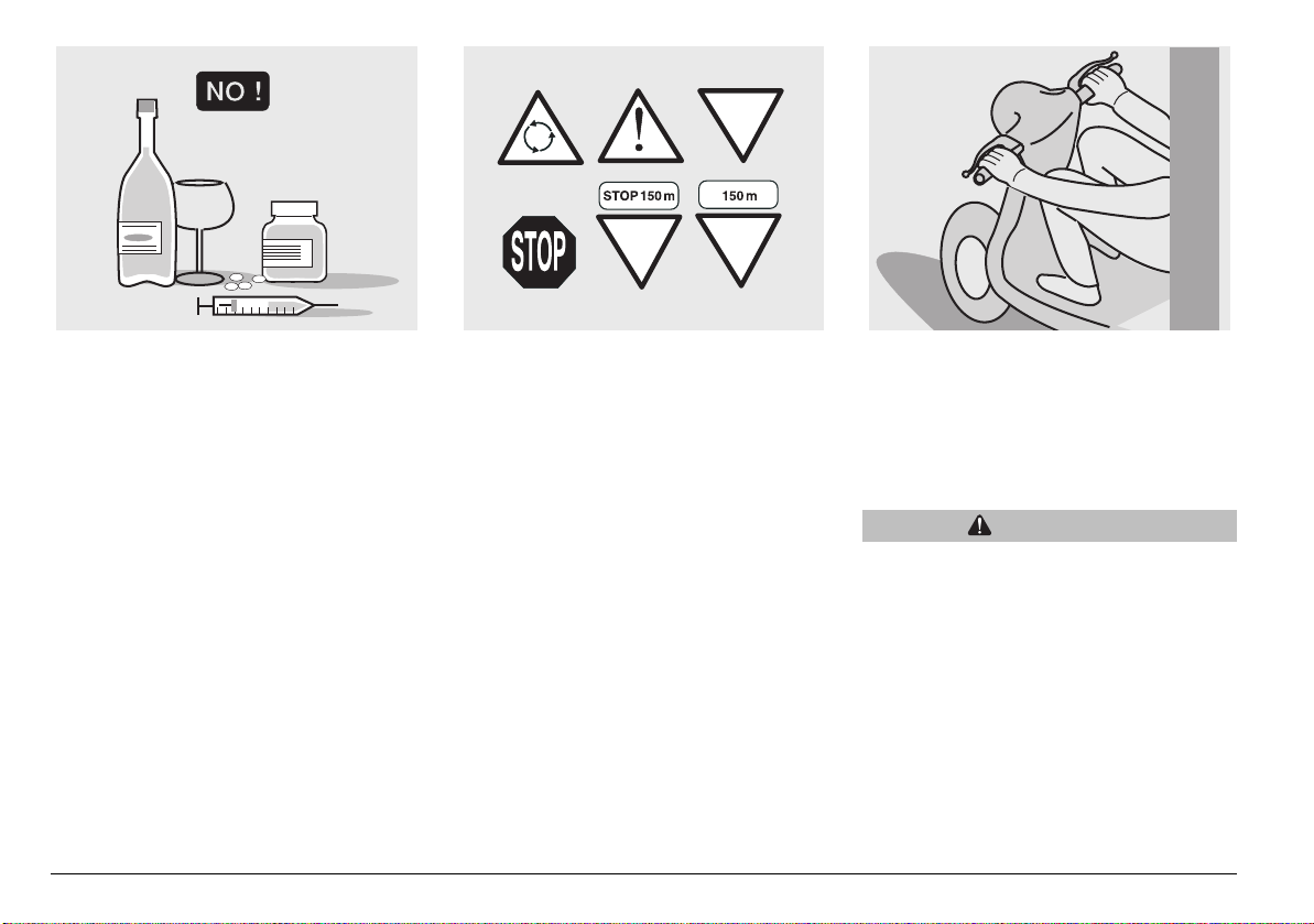
The use of medicines, alcohol and drugs or
psychotropic substances notably increases
the risk of accidents.
Your riding is also affected by your
physical and mental condition - do not ride
if you are feeling ill, upset, tired or sleepy.
use and maintenance Griso
6
Most road accidents are caused by
inexperienced riders.
NEVER lend the vehicle to beginners and,
in any case, make sure that the rider has
all the requirements for driving.
Strictly observe all posted signs and
national and local road regulations.
Avoid any sudden or risky manoeuvres
that may endanger your and other people's
safety (for example: wheelies, speeding,
etc.), and adjust your riding style to road
surface conditions, visibility, etc.
Avoid obstacles that could damage the
vehicle or make you lose control of the
vehicle.
Avoid riding in the slipstream created by
preceding vehicles in order to increase
your speed.
WARNING
Always hold the handlebars with both
hands and keep both feet on the
footrests (or on the rider's footboards),
in the correct riding position.
Avoid standing up or stretching your
limbs while driving.
ONLY ORIGINALS
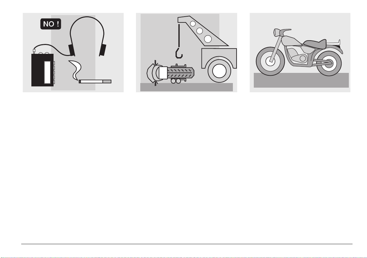
Do not allow yourself to become distracted
by other persons or by smoking, eating,
drinking, reading etc. when riding.
Use only the specified fuels and lubricants
indicated in the "LUBRICANT CHART" and
check oil, fuel and coolant levels at regular
intervals.
If the vehicle has been involved in an
accident, check the control levers, pipes
and hoses, wires, the braking system and
key components for damage.
If in doubt, have the vehicle inspected at a
Moto Guzzi Authorised Dealer and ask
them to carefully check the frame,
handlebars, suspensions, safety parts and
all devices whose inspection is best left to
a skilled mechanic.
Always remember to report any
malfunction to the technicians to help them
in their work.
Never use the vehicle when the amount of
damage it has suffered endangers your
safety.
Never change the position, inclination or
colour of: number plate, turn indicators,
lights and horns.
Any modification of the vehicle will result in
the invalidity of the guarantee.
Making any modifications to the vehicle
and/or removing the original components
can adversely affect vehicle performance
and safety or make it illegal to ride.
We recommend respecting all regulations
and national and local provisions regarding
the equipment of the vehicle.
In particular, avoid all modifications that
increase the vehicle’s performance levels
or alter its original characteristics.
Never race with other vehicles.
Do not ride off road.
use and maintenance Griso
7
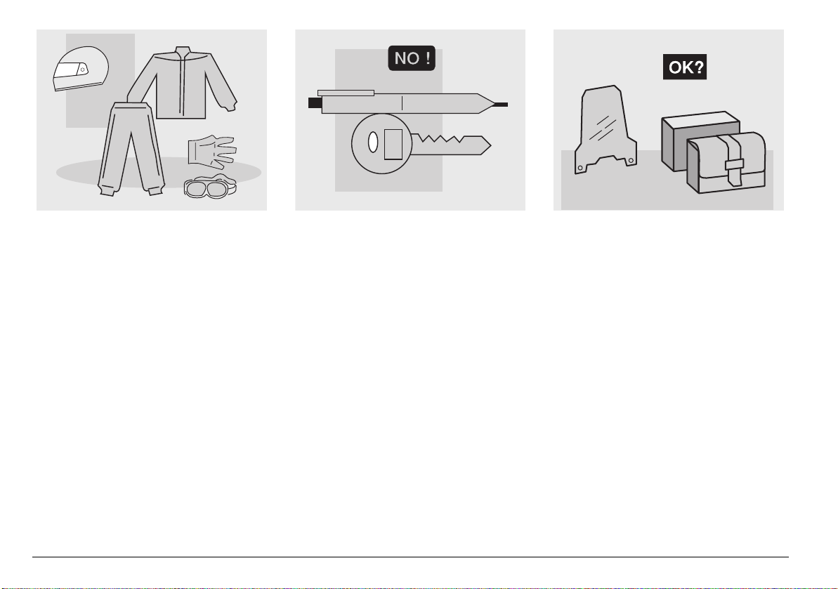
CLOTHING
Before starting, always wear a correctly
fastened crash helmet. Make sure that it is
homologated, in good condition, of the
right size and that the visor is clean.
Wear protective clothing, preferably in light
and/or reflecting colours. In this way you
will make yourself more visible to the other
riders, thus notably reducing the risk of
being knocked down, and you will be more
protected in case of fall.
This clothing should be very tight-fitting
and fastened at the wrists and ankles;
strings, belts and ties should not be
hanging loose; prevent these and other
objects from interfering with driving by
getting entangled with moving parts or
driving mechanisms.
use and maintenance Griso
8
Do not ride with sharp or pointed objects in
your pockets as they might cause injury in
the event of a fall
(this includes keys, pens, glass vials, etc. note that the same applies to your
passenger).
ACCESSORIES
The owner of the vehicle is responsible for
the choice, installation and use of any
accessory.
Avoid installing accessories that cover
horns or lights or that could impair their
functions, limit the suspension stroke and
the steering angle, hamper the operation of
the controls and reduce the ground
clearance and the angle of inclination in
turns.
Avoid using accessories that hamper
access to the controls, since this can
prolong reaction times during an
emergency.
Big fairings and windshields installed on
the vehicle may produce aerodynamic
forces that affect the stability of the vehicle,
especially when riding at high speed.
Make sure any accessories installed are
fastened securely to the vehicle and will not
affect safety during riding.
Do not install electrical devices and do not
modify those already existing to avoid
electrical overloads, because the vehicle
could suddenly stop or there could be a
dangerous current shortage in the horn and
in the lights.
Moto Guzzi recommends that you only use
genuine Moto Guzzi accessories.
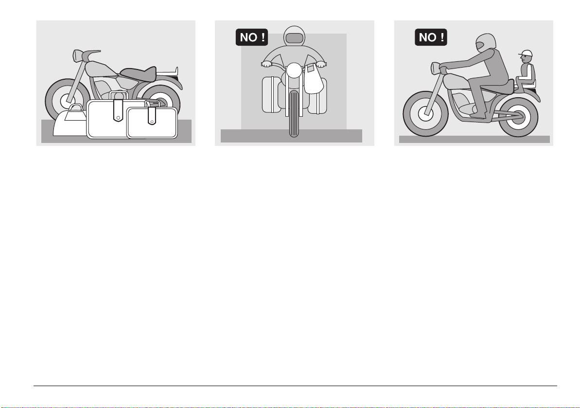
LOAD
Be careful not to overload the vehicle with
exceeding luggage. Place your luggage as
close as possible to the centre of gravity of
the vehicle and make sure its weight is
evenly distributed across both sides of the
vehicle to keep it stable. Furthermore, make
sure that the load is firmly secured to the
vehicle, especially during long trips.
Avoid fixing bulky, heavy and/or dangerous
objects to the handlebars, mudguards and
forks - this could slow down the vehicle's
response in turns and would inevitably
affect handling.
Do not secure bulky bags to the vehicle
sides, as they could hit people or obstacles
when riding, resulting in loss of control.
Do not carry any luggage unless firmly
secured to the vehicle.
Do not carry any bags which protrude too
much over luggage rack or cover the lights,
horn or indicators.
Do not carry pets or children sitting on the
glove compartment or on the luggage rack.
Do not exceed the maximum load capacity
of each luggage rack.
The overloaded vehicle will become
unstable and handle poorly.
use and maintenance Griso
9
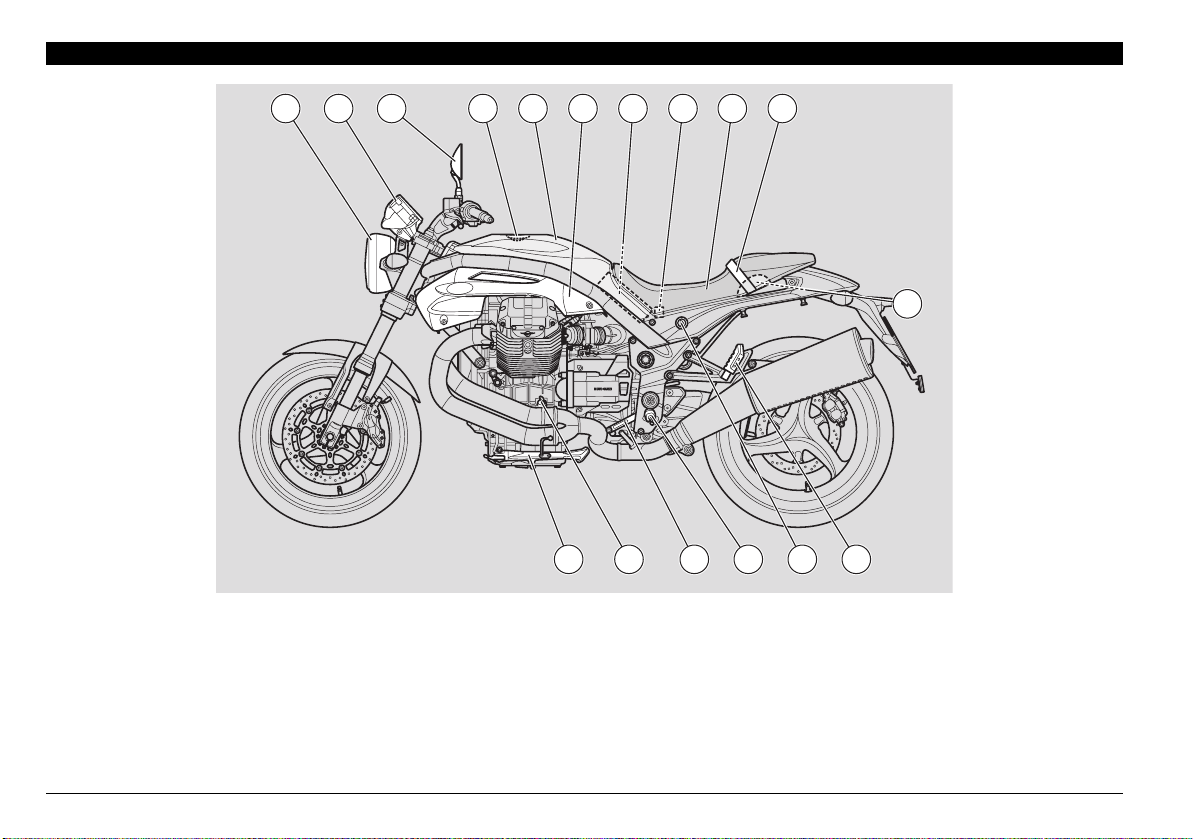
POSITION OF KEY COMPONENTS
KEY
1) Headlight
2) Instrument panel
3) Left rear-view mirror
4) Fuel tank filler cap
5) Fuel tank
6) Left side body panel
7) Battery
1 2 3 4
8) Main fuse carrier (30A)
9) Passenger/rider seat
10) Passenger grab strap
11) Tool kit compartment
12) Left passenger footpeg
13) Seat lock
14) Rider left footrest
5 6 1097 8
11
17 16 15 14 13 12
15) Gear shift lever
16) Engine oil dipstick
17) Side stand
use and maintenance Griso
10
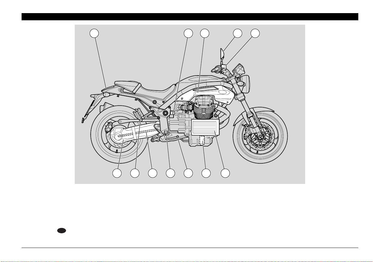
KEY
1) Tail light
2) Right side body panel
3) Rear brake fluid reservoir
4) Right rear-view mirror
5) Front brake fluid reservoir
6) Oil cooler
1100
7) Engine oil filter
1 2
3 4 5
12 11 10 9 8 7 6
8) Rear brake control lever
9) Right rider footrest
10) Cardan shaft
11) Right passenger footpeg
12) Single-sided swinging arm
use and maintenance Griso
11
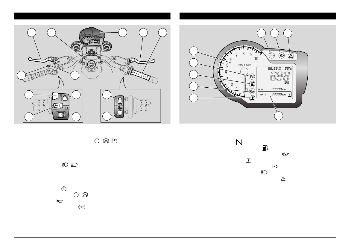
LOCATION OF INSTRUMENTS/CONTROLS
INSTRUMENTS AND INDICATORS
1 2 3 4 5
9 8
7
12
13
6
11
10
LOCATION OF INSTRUMENTS/CONTROLS - KEY
1) Clutch lever
2) Ignition switch/steering lock ( - - )
3) Instruments and indicators
4) Front brake lever
5) Throttle grip
6) Dimmer switch ( - )
7) Display functions switch
8) High beam flasher - passing button
9) SET push-button
10)Starter button ( )
11)Engine stop switch ( - )
12)Horn button ( )
13)Turn indicator switch ( )
6 7 8
1
2
3
4
5
9
LOCATION OF INSTRUMENTS/CONTROLS - KEY
1) Revolution counter
2) Green neutral light ( )
3) Orange low fuel warning light ( )
4) Red engine oil pressure warning light ( )
5) Yellow side stand light ( )
6) Green turn indicator warning light ( )
7) Blue high beam warning light ( )
8) Red alarms/immobiliser warning light ( )
9) Multifunction digital display.
use and maintenance Griso
12

INSTRUMENTS AND INDICATORS TABLE
When the ignition key is turned to " " with the engine stopped, all warning lights come on for a LED check-up and go out after three
seconds. If one or more warning lights do not come on at this stage, contact a Moto Guzzi Authorised Dealer.
Description Function
Speedometer (km/h MPH)
Odometer
Displays current, average or maximum riding speed (in kilometres or miles) depending on
presetting, see page 15 (MULTIFUNCTION COMPUTER).
Displays partial or total Km/miles run, see page 15 (MULTIFUNCTION COMPUTER).
(KM - Mi)
Ambient
temperature (°C/°F)
Displays ambient temperature, the value is shown in the top right corner of the display. When
temperature is close to 3° C (37 °F) the ice symbol should be displayed. Range in °C or °F is
selected through the display, see page 15 (MULTIFUNCTION COMPUTER).
Clock Displays time (hour and minutes) as preset, see page 15 (MULTIFUNCTION COMPUTER).
Multifunction
digital display
Battery voltage V
BATT
Displays the battery voltage in Volts, see page 15 (MULTIFUNCTION COMPUTER).
Lap timer Displays the different lap times, as preset, see page 15 (MULTIFUNCTION COMPUTER).
In case a serious failure is detected, one that might jeopardise the vehicle or the rider's safety,
the panel will show an icon indicating the failure cause (such as: oil pressure , maintenance
intervals ).
Diagnosis
CAUTION
If the wording " SERVICE" appears during normal engine
operation, it means that the ECU or the instrument panel have
detected a failure. In most cases, the engine will keep running, although giving less
performance. Immediately contact a
Moto Guzzi Authorised Dealer.
Indicates the number of revolutions of the engine per minute.
Revolution counter rpm
CAUTION
Never exceed the engine max. speed rate, see page 48 (RUNNING-
IN).
Continued X
use and maintenance Griso
13
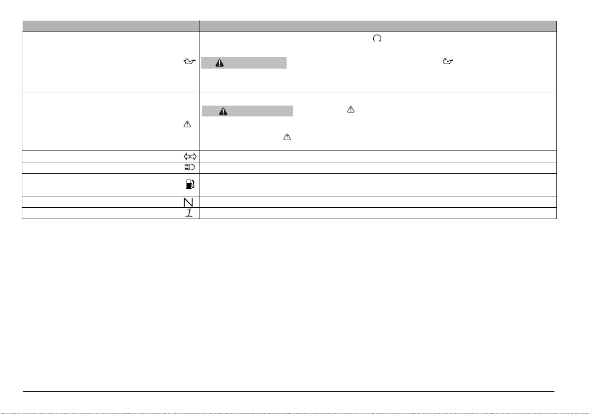
Description Function
Comes on when the ignition switch is set to " " with the engine stopped as a lamp test.
If the light does not come on in this phase, contact a
Engine oil pressure Warning light
CAUTION
that the engine oil pressure in the circuit is insufficient. In this case, stop the engine
immediately and contact a
W
orks as general alarm warning (excluded the engine oil pressure one) and gear shift indicator.
CAUTION
Alarm led
Turn indicator warning light Blinks when the direction indicators are on.
High beam warning light Comes on when the high beam bulbs are on or when the headlight signaller is operated.
Low fuel warning light
Neutral indicator warning light Comes on when the gear is in neutral.
Side stand down light Turns on when the side stand is down.
detected a failure; immediately contact a Moto Guzzi Authorised Dealer.
If LED warning light " " flashes when the vehicle is off it means that immobiliser or optional
antitheft alarm have been enabled.
Comes on when the quantity of fuel left in the tank is approx. 3.3
In this case, top up as soon as possible, see page 28 (FUEL).
If the engine oil pressure warning light remains on after the start
or comes on during the normal operation of the engine, this means
Moto Guzzi Authorised Dealer.
If the LED " " stays on after the engine is started or comes on
during normal engine operation, it means that the control unit has
Moto Guzzi Authorised Dealer.
b.
use and maintenance Griso
14
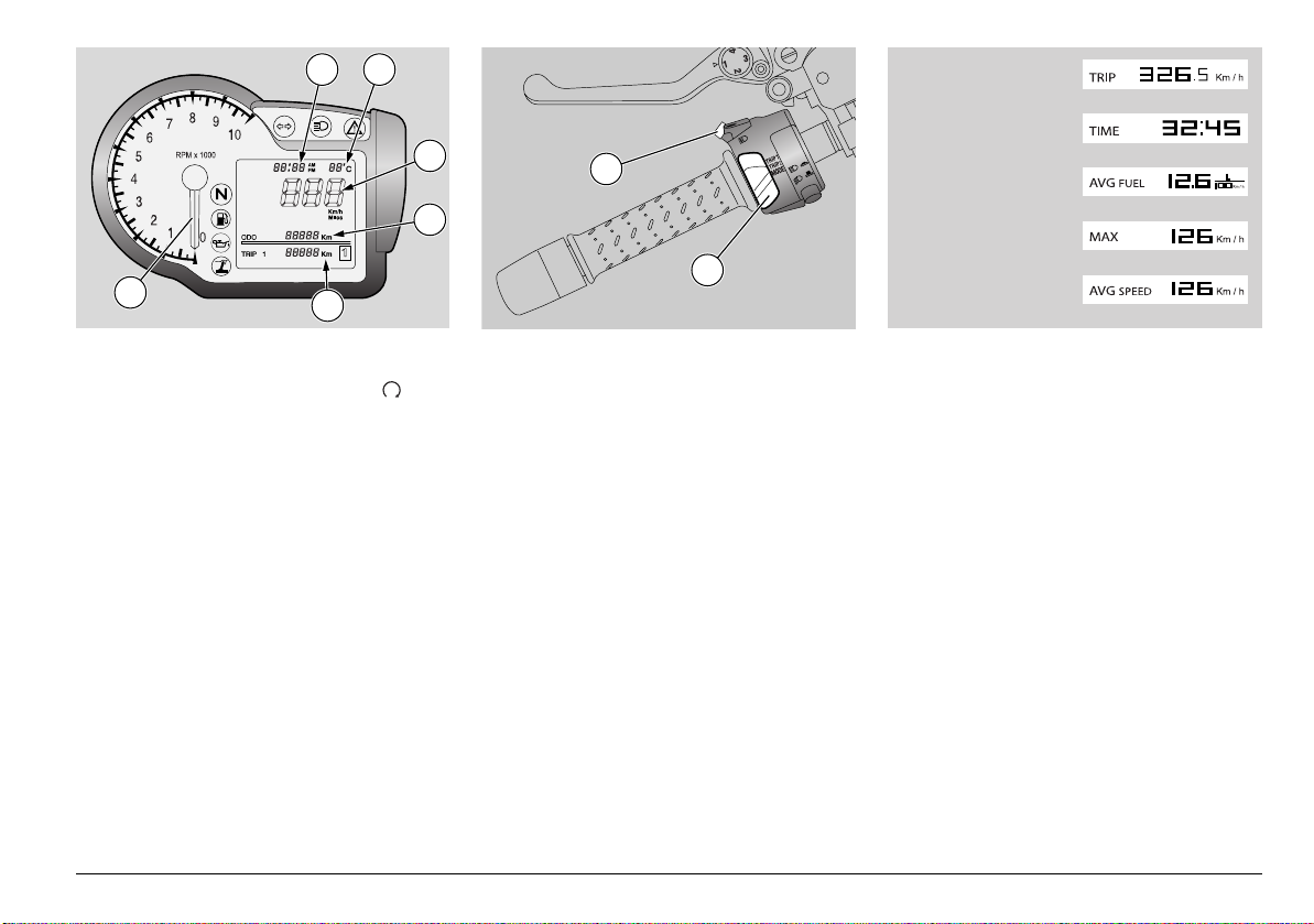
B D
A
3
C
TRIP METER
TRIP TIME
FUEL CONSUMPTION
MAXIMUM SPEED
2
1
E
AVERAGE SPEED
MULTIFUNCTION COMPUTER
When you turn the ignition key to " ", the
following instrument panel lights will turn
on for 2 seconds:
- the "GRISO" logo
- all warning lights
- backlighting
Rev counter index (1) moves to maximum
value, as set by the user.
After 2 seconds, all instruments will briefly
show the current values of the
corresponding parameters.
The display shows the following standard
settings:
– speed (zone a)
– clock (zone B)
– odometer (zone C)
– ambient temperature (zone D)
– on-board computer and accessories
functions (zone E)
CONTROLS
2) Switch with three positions: TRIP1 /
TRIP2 / MODE
3) SET button; briefly press it to scroll the
functions in the menus, press for
several seconds to confirm selected
option.
TRIP 1 AND 2
In TRIP 1 and 2 the data concerning trip 1
and 2 are shown.
Indication of displayed trip meter is on the
right, at the bottom.
Set selector (2) to the position
corresponding to TRIP configuration to be
displayed (TRIP 1 or TRIP 2).
At the bottom (F) are the following data:
–TRIP METER
–TRIP TIME
– FUEL CONSUMPTION
– MAXIMUM SPEED
– AVERAGE SPEED
Briefly press SET (3) to toggle between
these parameters. Press it for several
seconds to reset all data from selected
TRIP meter.
use and maintenance Griso
15
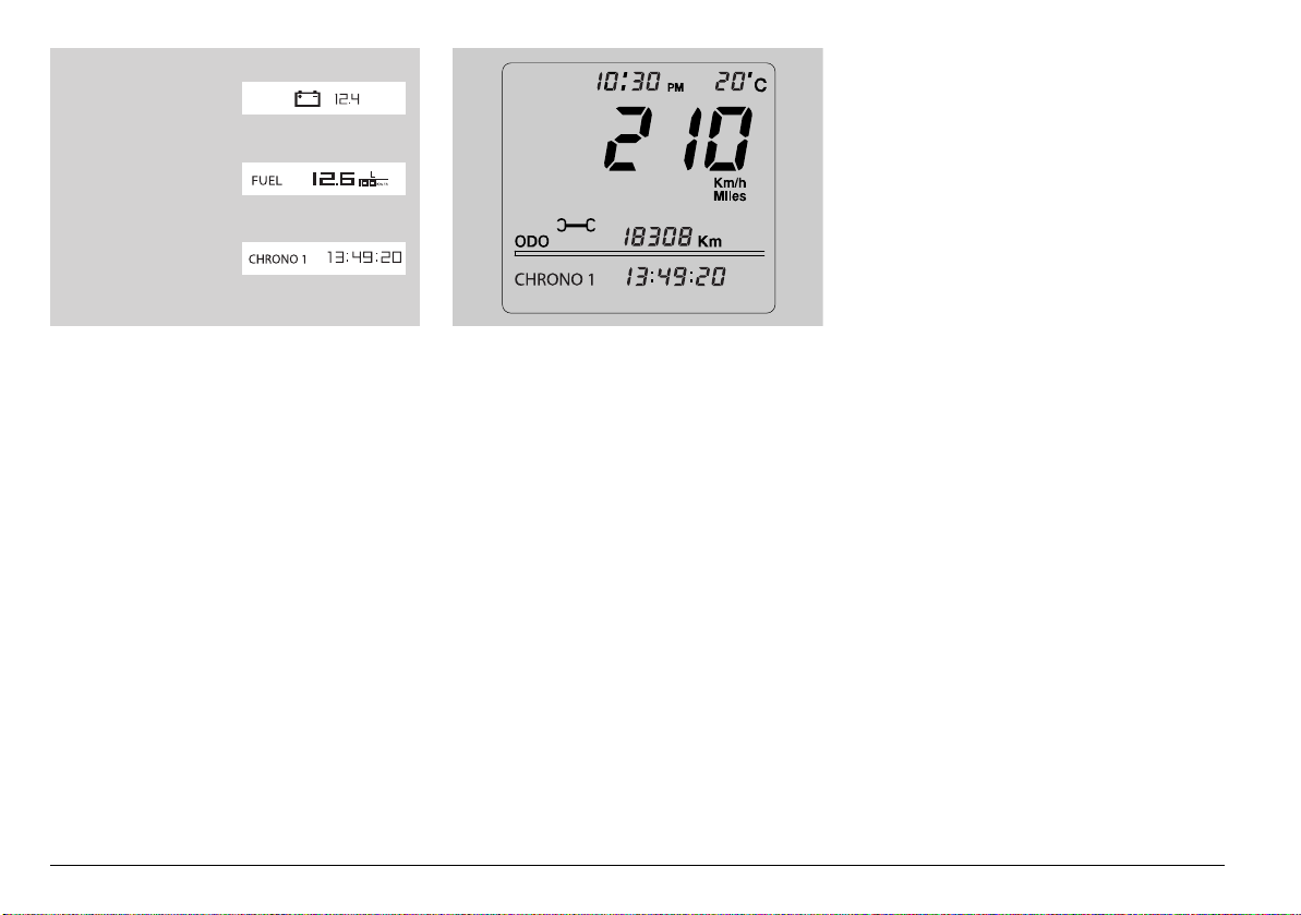
BATTERY VOLTAGE
INSTANT FUEL
CONSUMPTION
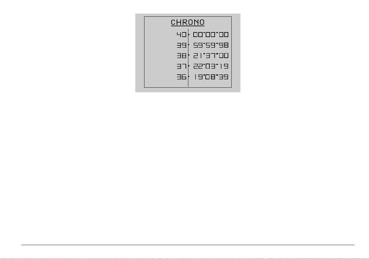
LAP TIMER
Acquisition ends as soon as 40 lap times
are stored; “FULL” is displayed. Stop the
vehicle, see page 49 (STOPPING) and
enter the VIEW TIMES function of the LAP
TIME menu to read the stored lap times.
MODE
MODE configuration features the functions
allowing the user to interact with the
system.
Set selector (2) to MODE position to select
MODE configuration.
At the bottom (F), the following data are
alternately displayed every time the SET
button (3) is pressed:
– BATTERY VOLTAGE
– INSTANT FUEL CONSUMPTION
– LAP TIMER
– MENU (function disabled when vehicle is
in motion)
BATTERY VOLTAGE and INSTANT FUEL
CONSUMPTION do not allow interaction
with the user.
use and maintenance Griso
16
LAP TIME
From MODE configuration, briefly press
SET button (3) and select LAP TIME
function to use the lap timer. At the bottom
(F) of the display "CHRONO" appears and
the number of the last time measured is
next to it, together with time measured.
Briefly press SET button (3) to start
recording a new session with the lap timer.
Press again the SET button (3) within the
first 10 seconds from when the timer starts,
time measurement is cancelled and a new
one is started. Press again the SET button
(3) after 10 seconds have elapsed from
timer start, time measurement is stopped,
stored and a new one is started. Stop the
time measurement session by pressing the
SET (3) push-button for several seconds.
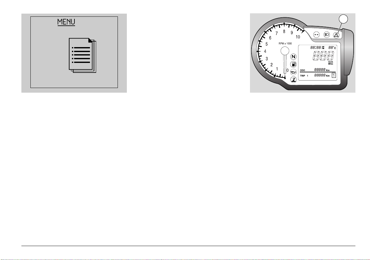
MENU
If vehicle is stopped and selector is set to
MODE, configuration menu of the MENU
page can be accessed. To enter this
function, confirm MENU selection [press
SET button (3) for several seconds].
Configuration menu options are:
– EXIT
– SETTINGS
– LAP TIMER
– DIAGNOSTICS
– LANGUAGE
SETTINGS
When confirming SETTINGS selection
(pressing SET button (3) for several
seconds) the following options are
displayed:
– EXIT
– TIME SETTINGS
– GEAR SHIFT INDICATOR
– BACK LIGHTING
–°C/°F
– 12H/24H
– CHANGE THE CODE
– CODE RECOVERY
Time settings
This mode allows you to set the clock. In
this function, hours increase by one unit
every time the SET button (3) is pressed;
when value is 12 or 24, it goes back to 1 if
the SET button (3) is pressed again.
AM indication becomes PM or vice versa
when time goes from 11:59 to 12:00.
Press the SET button (3) for several
seconds to store the value and go to
minutes setting mode. Minutes increase by
one unit every time the SET button (3) is
pressed; when value is 59, it goes back to
0 if the SET button (3) is pressed again.
Press the SET button (3) for several
seconds to complete the procedure; the
instrument panel sets back to SETTINGS
menu.
Gear shift indicator
This function allows you to set the value for
the Gear shift indicator threshold. As soon
as you enter this function, the display
shows “GEAR SHIFT INDICATOR” (if
English is the selected language) and the
rev counter scale indicates the threshold
value.
4
Briefly press the SET (3) push-button to
increase threshold value by 100 RPM.
Once the top limit has been reached, press
the push-button again to decrease the
value.
Press the SET button (3) for several
seconds to complete the operation; the
display sets back to SETTINGS menu.
When battery is connected for the first
time, the instrument panel sets to runningin rpm value, the next time battery is
connected it sets to last set value.
– RUNNING-IN RPM: 6500
– MINIMUM RPM (THAT CAN BE SET):
6000
– MAXIMUM RPM (THAT CAN BE SET):
8500
When the set threshold is exceeded, the
alarm light (4) on the instrument panel
flashes until the value goes below the
threshold.
use and maintenance Griso
17
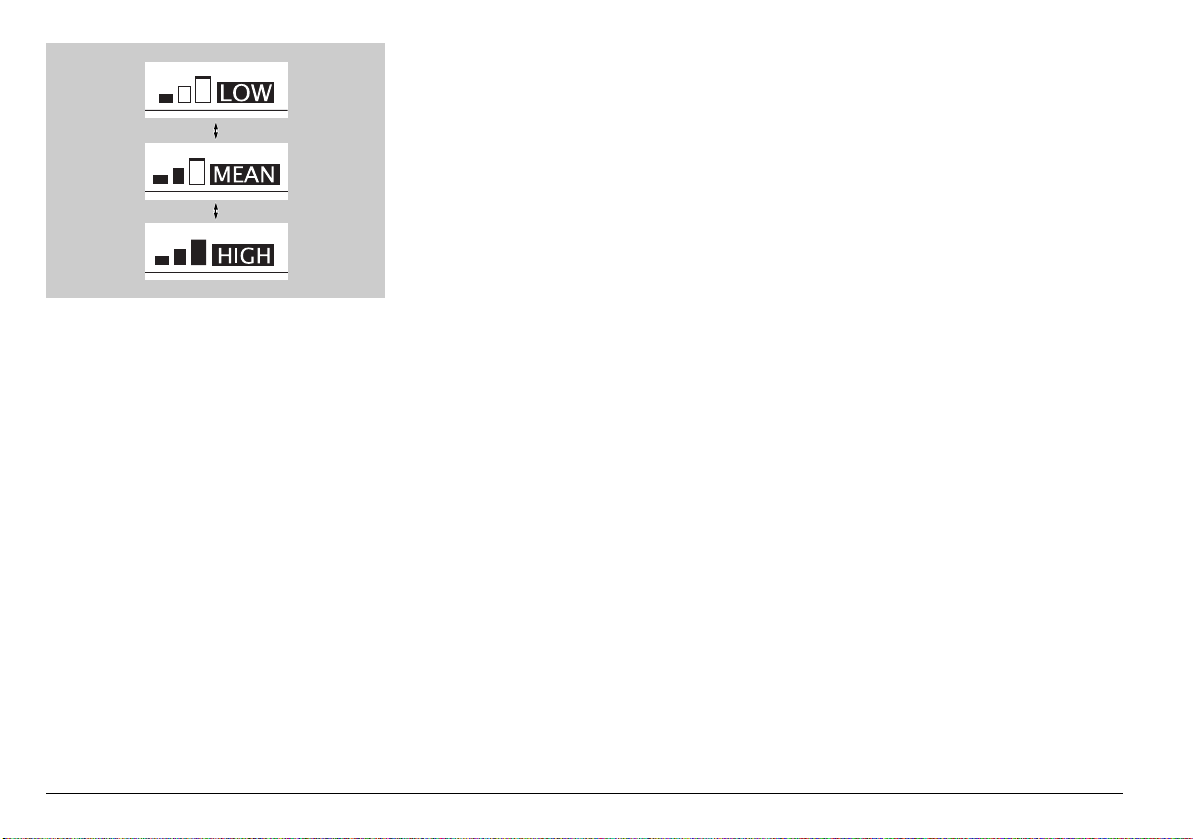
Back lighting
This function allows you to set
backlighting: three levels are available.
From this function, every time the SET
button (3) is briefly pressed, the following
icons are alternately displayed:
–LOW
– MEAN
–HIGH
Press the SET button (3) for several
seconds to complete the operation; the
instrument panel sets back to SETTINGS
menu.
°C/°F
This function allows you to select the unit
of measurement for ambient temperature.
From this function, every time the SET
button (3) is briefly pressed, the following
two units of measurement are alternately
displayed:
°C
°F
Press the SET button (3) for several
seconds to store the data; the instrument
panel sets back to SETTINGS menu.
12H/24H
This function allows you to select the time
format. From this function, every time the
SET button (3) is briefly pressed, the
following formats are alternately displayed:
12H
24H
Press the SET button (3) for several
seconds to store the data; the instrument
panel sets back to SETTINGS menu.
Change the code
This function is used when the old code is
available and is to be changed.
Within this function, the following message
is displayed:
"INSERT THE OLD CODE"
As soon as the old code is acknowledged,
the new code is requested; the following
message is displayed:
"INSERT THE NEW CODE"
Once the operation is over, the display
goes back to DIAGNOSIS menu. If you
entered with the code, this operation will
not be allowed.
Once the operation is over, the instrument
panel goes back to SETTINGS menu.
use and maintenance Griso
18
Code recovery
This function is used when the old code is
not available and you need to change it. In
this case it is necessary to insert at least
two keys in the ignition switch. The first key
is already inserted, a second key is
requested with the message:
"INSERT THE 2nd KEY"
The instrument panel remains on in-
between these two keys; if the second key
is not inserted within 20 seconds the
operation is aborted. When the second key
is acknowledged, the new code is
requested with the message:
"INSERT THE NEW CODE"
Once the operation is over, the display
goes back to DIAGNOSIS menu. If you
entered with the code, this operation will
not be allowed.
Once the operation is over, the instrument
panel goes back to SETTINGS menu.
LAP TIMER
When confirming LAP TIMER selection
[pressing SET button (3) for several
seconds] the following options are
displayed:
– EXIT
– VIEW TIMES
– DELETE TIMES
View times
This function also displays the acquired lap
times. Briefly press the SET button (3) to
scroll the pages with the times measured;
press it for several seconds to set the
display to LAP TIME menu. If the battery is
disconnected, stored times are lost.
Delete times
This function deletes the acquired lap times.
Deletion should be confirmed. Once the
operation is over, the display goes back to
LAP TIMER menu.
DIAGNOSIS
This function interfaces with the systems
fitted to the motorcycle to carry out
diagnosis. To enable it, you need a special
password only available to the Moto Guzzi
Authorised Dealer.
LANGUAGE
This function allows you to choose the
language of any message displayed.
Available options are:
– ITALIANO
– ENGLISH
– FRANCAIS
– DEUTSCH
– ESPAGNOL
Once the operation is over, the display
goes back to LANGUAGE menu.
use and maintenance Griso
19
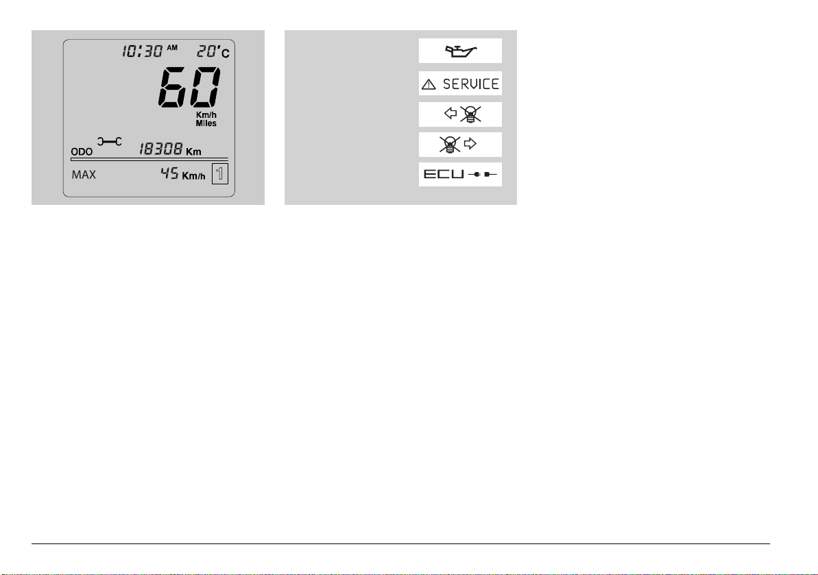
ENGINE OIL PRESSURE
ECU ERRORS,
INSTRUMENT PANEL ERRORS
LEFT DIRECTION
INDICATOR FAULT
RIGHT DIRECTION
INDICATOR FAULT
ECU DISCONNECTED
SERVICE INTERVAL
When the scheduled service intervals are
reached, an icon is displayed (symbol of a
spanner).
Switches on first at: 1,500 km
Then switches on: every 10,000 km
use and maintenance Griso
20
ALARM DISPLAY
In case a serious failure is detected, one
that might jeopardise the vehicle or the
rider's safety, the display will show an icon
indicating the failure cause, at the bottom
(F).
Alarms are divided in two groups
depending on their priority:
High priority: Engine oil pressure, Errors
from control unit and instrument panel
errors.
Low priority: Turn indicators and Control
unit disconnect.
If there are many alarms with the same
priority level, the relevant icons are
displayed alternately.
High priority alarms do not allow you to
display low priority ones.
If the alarm light and the SERVICE icon
briefly come on, it does not mean that there
is a failure.

MAIN INDEPENDENT CONTROLS
6 5
2
1
4 3
CONTROLS ON LEFT HANDLEBAR
NOTE The electric components only operate when the ignition
switch is in the
1) TURN INDICATORS SWITCH ( )
Move the switch to the left, before turning left; move it to the
right before turning right. Press the switch to turn off the
direction indicator.
2) HORN BUTTON ( )
Press it to operate the horn.
“” position.
NOTE The indicator LED flashing quickly indicates that one or
both turn indicator bulbs are burnt out. For replacement
instructions, please see page 77 (CHANGING THE FRONT AND
REAR TURN INDICATOR BULBS).
3) LIGHT DIMMER SWITCH: Set it to “ ” to operate the high
beam; set it to “ ” to operate the low beam.
4) DISPLAY CONFIGURATION SELECTOR:
Select the displayed configuration, see page 15
(MULTIFUNCTION COMPUTER).
5) HIGH BEAM FLASHER BUTTON ( )
Allows for the use of the passing lights in case of danger or
emergency.
NOTE Release the button to turn off the high beam flasher.
6) SET BUTTON
Button to scroll and select the displayed menus, see page 15
(MULTIFUNCTION COMPUTER).
use and maintenance Griso
21
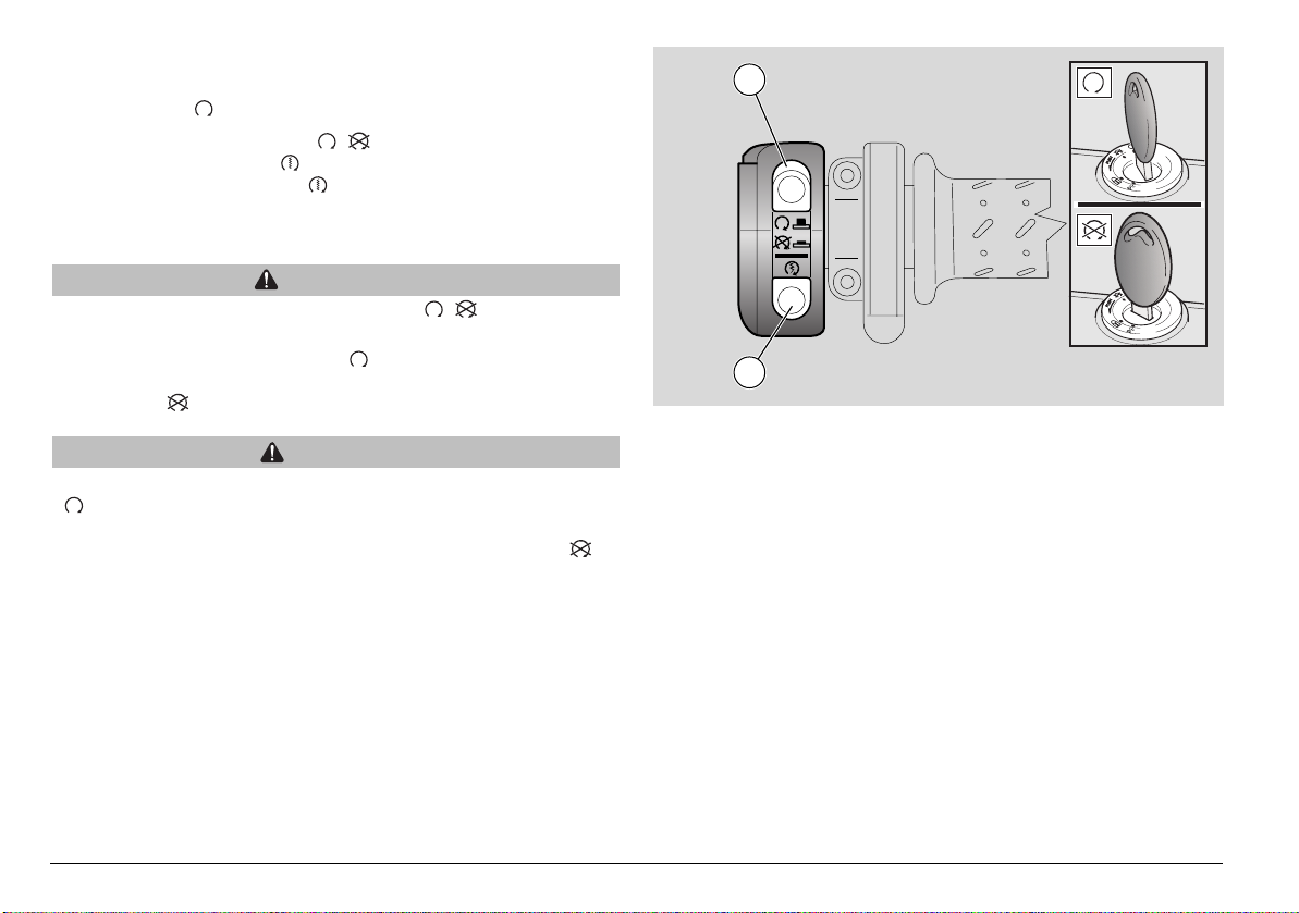
CONTROLS ON RIGHT HANDLEBAR
NOTE The electric components only operate when the ignition
switch is in the “ ” position.
7) ENGINE STOP SWITCH (-)
8) STARTER BUTTON ()
When the starter button " " is pressed, the starter motor will
crank the engine. See page 43 (STARTING) for the starting
procedure.
WARNING
Do not operate the engine stop switch " - " while riding.
This switch serves as a safety or emergency switch. With the
switch pressed in position “ ”, it is possible to start the
engine; the engine can be stopped by pressing the switch to
position “ ”.
CAUTION
With the engine stopped and the ignition switch in position
" ", the battery may wear down.
When the vehicle has come to a standstill and you have
stopped the engine, set the ignition switch to position " ".
7
8
use and maintenance Griso
22
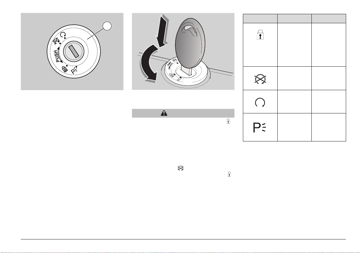
1
IGNITION SWITCH
The ignition switch (1) is mounted to the
top yoke of the steering shaft.
NOTE The key operates the ignition
switch/steering lock, the fuel tank lock and
the seat lock.
Two keys are supplied together with the
vehicle (one spare key).
NOTE Do not keep the spare key on the
vehicle.
NOTE Up to 4 keys can be stored. For
this procedure it is advisable to contact a
Moto Guzzi Authorised Dealer.
STEERING LOCK
WARNING
Never turn the key to position " "
when riding, or you will lose control of
the vehicle.
OPERATION
To lock the steering:
u Turn the handlebar fully to the left.
u Turn the key to " ".
u Press the key in and turn it to “ ”
position.
NOTE If necessary, turn on the parking
lights, see page 24 (PARKING LIGHTS).
u Remove the key.
Position Function Key removal
It is possible
to remove the
key.
It is possible
to remove the
key.
It is not
possible to
remove the
key.
It is possible
to remove the
key.
Steering lock
The steering
is locked.
It is not
possible to
start the
engine or
switch on the
lights.
Neither the
engine, nor
the lights will
operate.
The engine
and the lights
can be
operated.
The engine
can not be
started and
the parking
lights are on
use and maintenance Griso
23
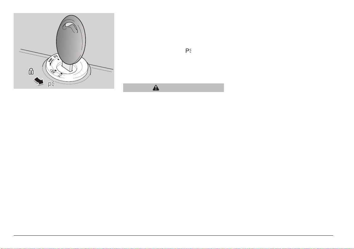
PARKING LIGHTS
The vehicle is equipped with front and rear
parking lights. It is always recommended to
park the vehicle in the suitable areas and in
any case in lighted locations. If this is not
possible, the parking lights are useful
whenever it is necessary to park in a dark
or poorly lit area and in any case to make
the vehicle more visible.
OPERATION
To turn the parking lights on:
u Lock the steering but do not remove the
key (1), see page 23 (STEERING
LOCK).
u Turn the key (1) to “ ” (PARKING)
position.
u Check that both front and rear parking
lights are on.
u Remove the key (1).
CAUTION
The parking lights drain the battery. Do
not leave them on for long periods of
time to avoid the battery from wearing
down. A dead battery prevents you from
starting the vehicle.
use and maintenance Griso
24
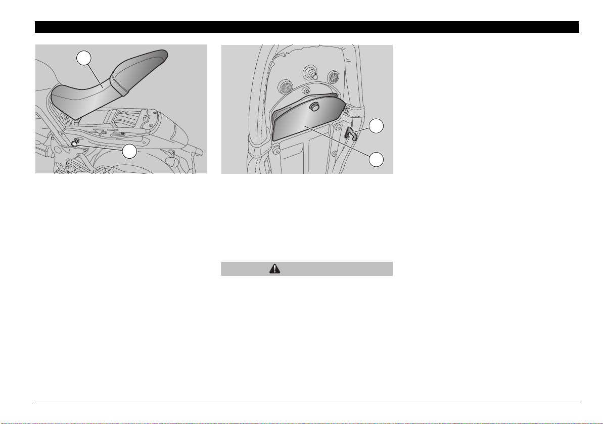
AUXILIARY EQUIPMENT
2
TOOL KIT COMPARTMENT
To gain access to the tool kit
compartment:
u Remove the seat, see
(UNLOCKING/LOCKING THE SEAT), in
this page.
u Remove the cover (3).
4
1
UNLOCKING/LOCKING THE SEAT
u Place the vehicle on the stand, see page
50 (PUTTING THE VEHICLE ON THE
STAND).
u Insert the key (1) into the seat lock.
u Turn the key (1) clockwise and push
softly onto the rear seat middle to
facilitate pin release, then lift and slide
out the seat (2) from behind.
NOTE Before lowering and locking the
seat (2), make sure that you have not left
the key in the tool kit compartment.
3
To lock the seat (2):
u Slide the seat front end into place.
u Lower the rear end and position the seat
so that the two hooks (4) are correctly
hooked to the frame fasteners.
u Push down on the middle of the rear end
until the lock clicks shut.
WARNING
Before riding, make sure that the seat
(2) is properly locked.
use and maintenance Griso
25
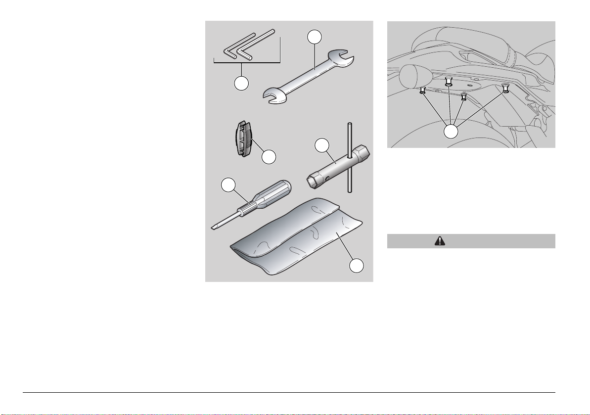
The tool kit includes:
– 4, 5 mm bent Allen spanners (1);
– 10 - 13 mm double fork spanner (2);
– 21 - 22 mm socket spanner (3);
– double-ended cross-head/flat-blade
screwdriver (4);
– fuse removing tool (5);
– tool box (6).
2
1
10
3
5
4
LUGGAGE ANCHOR POINTS
It is possible to fix a small luggage to the
seat rear end, it can be positioned using
elastic bands to be secured to the four
elements (10).
Maximum allowed weight: 5 kg.
WARNING
Carry small luggage only and make sure
6
it is fastened securely.
use and maintenance Griso
26
1 2
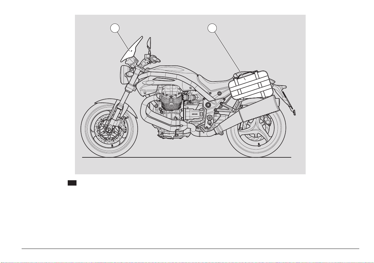
ACCESSORIES
OPT
The following accessories are available:
1) headlight fairing
2) side panniers
– luggage rack
– luggage rack bag
– tank bag (two sizes available).
use and maintenance Griso
27
 Loading...