

MOTO GUZZI Engine V1100 Workshop Manual

workshopmanual
00/2005-10
Engine V1100
UK
Cod.
USA
Cod. 8140899

INTRODUCTION
0-1
Engine V1100
INTRODUCTION 0

INTRODUCTION
0 - 2
Engine V1100
TABLE OF CONTENTS
0.1. INTRODUCTION .............................................................................................................................................. 3
0.1.1. FOREWORD ............................................................................................................................................. 3
0.1.2. REFERENCE MANUALS .......................................................................................................................... 4
0.1.3. ABBREVIATIONS/SYMBOLS/CONVENTIONS ........................................................................................ 5

INTRODUCTION
0-3
Engine V1100
0.1. INTRODUCTION
0.1.1. FOREWORD
This manual provides the information required for normal servicing.
This publication is intended for use by Moto Guzzi Dealers and their qualified mechanics; certain information has been
omitted intentionally, as this manual does not purport to provide a comprehensive treatise on mechanics. The persons
who will use this manual must be fully conversant with the basics of mechanics and with the basic procedures of
motorcycle repair. Without such familiarity, repairs and checks could be ineffective and even hazardous. Since the repair
and vehicle check instructions are not exhaustive, special care must be taken to avoid damage and injury. Repairing or
inspecting a motorcycle when one does not possess such basic knowledge or training could result in improper servicing
and make the motorcycle unsafe to ride. For the same reason, certain basic precautions have been omitted in the
descriptions of repair and inspection procedures; you are therefore invited to take special care to avoid damage to
motorcycle components or injury to persons. Moto Guzzi s.p.a. undertakes to constantly improve the design of its
products and the relevant literature to ensure that the customer is satisfied with the product. The main technical
modifications and changes in repair procedures are communicated to all Moto Guzzi dealers and agencies worldwide.
Such modifications will be included in subsequent editions of the manual. Should you require assistance or clarifications
regarding inspection and repair procedures, please contact the Moto Guzzi SERVICE DEPT., which will be pleased to
help, as well as providing you with updates and technical modifications regarding the vehicle.
Moto Guzzi s.p.a. reserves the right to make changes to its products at any time, barring any such changes as may alter
the essential features of a product as specified in the relevant manual.
All rights of storage using electronic means, reproduction and total or partial adaptation, whatever the means adopted,
are reserved in all countries.
The mention of third parties’ products is only made for information purposes, and constitutes no engagement.
Moto Guzzi s.p.a. is not liable in any way for the performance or use of these products.
For further details, see REFERENCE MANUALS.
First edition: October 2005
Produced and printed by:
VALLEY FORGE DECA
Ravenna, Modena, Torino
DECA S.r.l.
via Vincenzo Giardini, 11
48022 Lugo (RA) - Italy
Tel. +39 - 0545 216611
Fax +39 - 0545 216610
E-mail: deca@vftis.spx.com
www.vftis.com
On behalf of:
Moto Guzzi s.p.a.
via E.V. Parodi, 57- 23826 Mandello del Lario (Lecco) - Italy
Tel. +39 – 0341 - 709111
Fax +39 – 0341 - 709220
www.motoguzzi.it
www.servicemotoguzzi.com

INTRODUCTION
0 - 4
Engine V1100
0.1.2. REFERENCE MANUALS
PARTS CATALOGUES
guzzi part# (description)
GU077_00
OWNER'S MANUALS
guzzi part# (description)
05.90.00.30
05.90.00.31
CHASSIS WORKSHOP MANUAL
guzzi part# (description)
8140856
8140857
8140858
8140859
8140860
8140861
8CM0077
8CM0078
ENGINE WORKSHOP MANUAL
guzzi part# (description)
8140894
8140895
8140896
8140897
8140898
8140899
CD FOR THE NETWORK
guzzi part# (description)
8CM0093
8CM0094

INTRODUCTION
0-5
Engine V1100
0.1.3. ABBREVIATIONS/SYMBOLS/CONVENTIONS
# = number
< = less than
> = greater than
≤ = less than or equal to
≥ = greater than or equal to
~ = approximately
∞ = infinity
°C = degrees Celsius (centigrade)
°F = degrees Fahrenheit
± = plus or minus
A.C. = alternating current
A = Ampere
Ah = Ampere per hour
API = American Petroleum Institute
AT = high voltage
AV/DC = Anti-Vibration Double Countershaft
bar = pressure measurement (1 bar = 100 kPa)
D.C. = direct current
cc = cubic centimeters
CO = carbon monoxide
CPU = Central Processing Unit
DIN = German industrial standards (Deutsche Industrie Norm)
DOHC = Double Overhead Camshaft
ECU = Electronic Control Unit
rpm = revolutions per minute
HC = unburnt hydrocarbons
ISC = Idle Speed Control
ISO = International Standardization OrganisationOrganization
kg = kilograms
kgm = kilogram meter (1 kgm = 10 Nm)
km = kilometers
km/h = kilometers per hour
kΩ = kilo Ohm
kPa = kiloPascal (1 kPa = 0.01 bar)
KS = clutch side (from the German "Kupplungsseite")
kW = kilowatt
l = liters
LAP = racetrack lap
LED = Light Emitting Diode
LEFT SIDE = left-hand side
m/s = meters per second
max = maximum
mbar = millibar (1 mbar = 0.1 kPa)
mi = miles
MIN = minimum
MPH = miles per hour
MS = flywheel side (from the German "Magnetoseite")
MΩ = MegaOhm
N.A. = Not Available
N.O.M.M. = Motor Octane Number
N.O.R.M. = Research Octane Number
Nm = Newton meter (1 Nm = 0.1 kgm)
Ω = ohm
PICK-UP = pick-up
BDC = Bottom Dead Center
TDC = Top Dead Center
PPC = Pneumatic Power Clutch
RIGHT SIDE = right-hand side
SAE = Society of Automotive Engineers
SAS = Secondary Air System

INTRODUCTION
0 - 6
Engine V1100
TEST = diagnostic check
T.B.E.I. = crown-head Allen screw
T.C.E.I. = cheese-head Allen screw
T.E. = hexagonal head
T.P. = flat head screw
TSI = Twin Spark Ignition
UPSIDEDOWN = inverted fork
V = volt
W = watt
Ø = diameter

GENERAL INFORMATION
1-1
Engine V1100
GENERAL INFORMATION 1

GENERAL INFORMATION
1 - 2
Engine V1100
TABLE OF CONTENTS
1.1. STRUCTURE OF THE MANUAL...................................................................................................................... 3
1.1.1. CONVENTIONS USED IN THE MANUAL ................................................................................................. 3
1.1.2. SAFETY WARNINGS ................................................................................................................................ 4
1.2. GENERAL RULES............................................................................................................................................ 5
1.2.1. BASIC SAFETY RULES ............................................................................................................................ 5
1.3. DANGEROUS ELEMENTS............................................................................................................................... 8
1.3.1. WARNINGS ............................................................................................................................................... 8
1.4. RUNNING-IN .................................................................................................................................................. 11
1.4.1. RUNNING-IN ........................................................................................................................................... 11
1.5. POSITION OF THE SERIAL NUMBERS ........................................................................................................ 12
1.5.1. POSITION OF THE SERIAL NUMBERS................................................................................................. 12
GENERAL INFORMATION
1-3
Engine V1100
1.1. STRUCTURE OF THE MANUAL
1.1.1. CONVENTIONS USED IN THE MANUAL
• This manual is divided in sections and subsections, each covering a set of the most significant components. For
quick reference, see the summary of sections.
• • Unless expressly specified otherwise, assemblies are reassembled by reversing the assembly procedure.
• • The terms "left" and "right" are referred to the motorcycle when viewed from the riding position.
• Motorcycle operation and basic maintenance are covered in the "OWNER'S MANUAL".
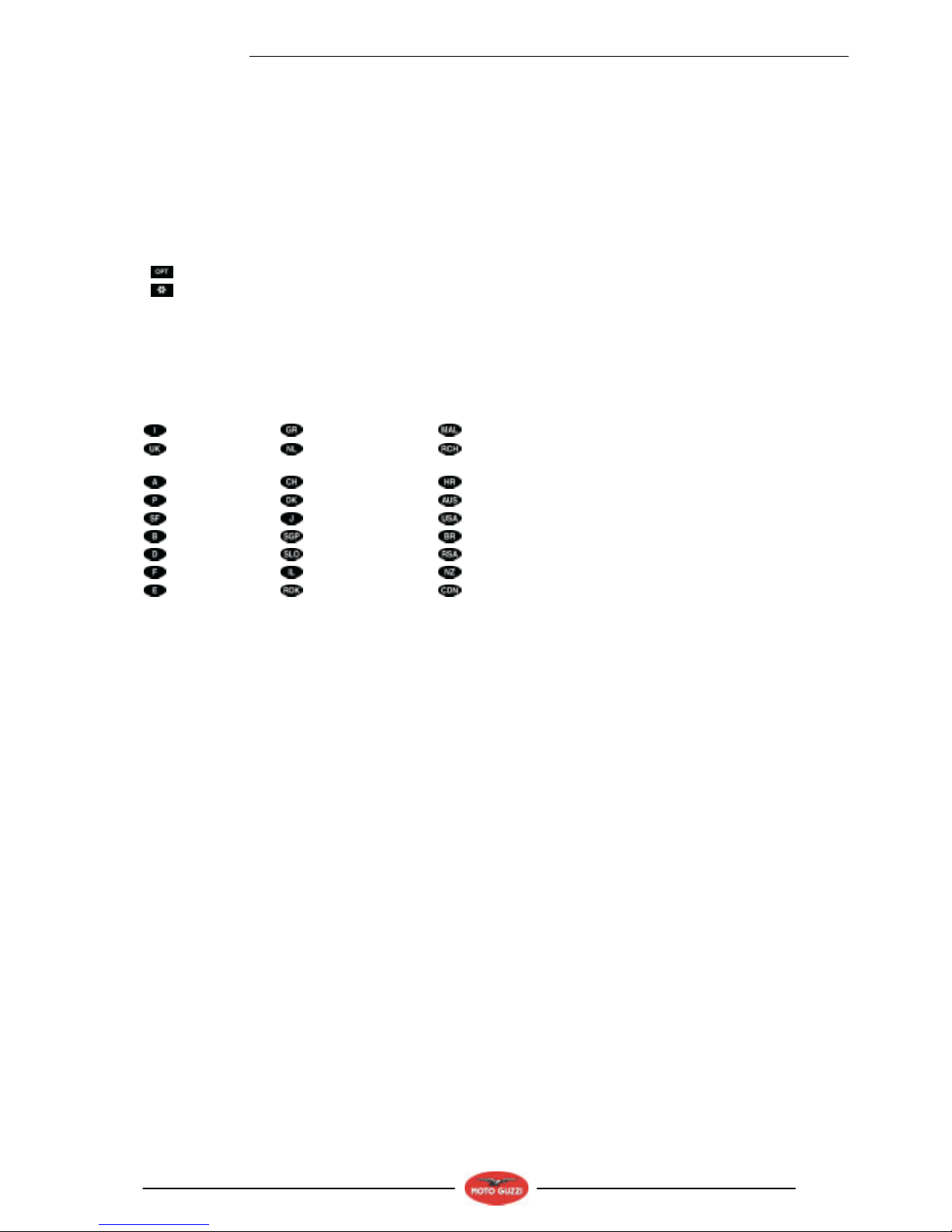
In this manual any variants are identified with these symbols:
optional
catalytic version
- all versions
MP national certification
SF European certification (EURO 1 limits)
VERSION:
Italy
Greece
Malaysia
United
Kingdom
Holland
Chile
Austria
Switzerland
Croatia
Portugal
Denmark
Australia
Finland
Japan
United States of America
Belgium
Singapore
Brazil
Germany
Slovenia
South Africa
France
Israel
New Zealand
Spain
South Korea
Canada
GENERAL INFORMATION
1 - 4
Engine V1100
1.1.2. SAFETY WARNINGS
The symbols and warnings used throughout this manual have the following meanings:
Safety warning. When you find this symbol on the vehicle or in the manual, be careful of the potential
risk of personal injury. Disregarding the instructions identified by this symbol may compromise the
safety of the user, the motorcycle and third parties.
DANGER
Indicates a potential hazard which may result in serious injury or even death.
WARNING
Indicates a potential hazard which may result in minor personal injury or damage to the vehicle.
NOTE The word "NOTE" in this manual identifies important information or instructions.
GENERAL INFORMATION
1-5
Engine V1100
1.2. GENERAL RULES
1.2.1. BASIC SAFETY RULES
CARBON MONOXIDE
When an operation must be performed with the engine running, position the motorcycle outdoors in a well-ventilated
area.
Never run the engine in an enclosed place.
Use an exhaust emission extraction system when working indoors.
DANGER
Exhaust gases contain carbon monoxide, a poisonous gas which, if inhaled, may cause loss of
consciousness or even death.
FUEL
DANGER
The fuel used to operate engines is highly flammable and becomes explosive under particular
conditions.
Refueling and maintenance operations should be carried out in a well-ventilated area, with the engine
off.
Do not smoke when refueling or in the proximity of sources of fuel vapors. Avoid contact with bare
flames, sources of sparks and any other source which may ignite fuel or lead to explosion.
DO NOT DISPOSE OF FUEL IN THE ENVIRONMENT.
KEEP AWAY FROM CHILDREN.
HOT COMPONENT PARTS
The engine and exhaust component parts become hot when the engine is running and will stay hot for some time after
the engine has been stopped.
Wear insulating gloves before handling these components or allow for the engine and the exhaust system to cool down
before proceeding.
USED GEARBOX AND FORK FLUIDS
DANGER
Wear latex gloves when servicing.
Prolonged or repeated contact with gear fluid may cause severe skin damage.
Wash your hands thoroughly after handling.
Dispose of it through the nearest waste oil reclamation firm or through the supplier.
Wear latex gloves when servicing.
DO NOT DISPOSE OF FLUID IN THE ENVIRONMENT.
KEEP AWAY FROM CHILDREN.
BRAKE FLUID
WARNING
Brake fluid can damage plastic, rubber or painted parts. When servicing the brake system, protect all
such parts with a clean cloth.
Always wear safety glasses when servicing the brake system.
Brake fluid is highly irritant. Avoid contact with the eyes.
In case of contact with the eyes, rinse abundantly with cool, clean water and immediately seek
medical attention.
KEEP AWAY FROM CHILDREN.
GENERAL INFORMATION
1 - 6
Engine V1100
HYDROGEN GAS AND BATTERY ELECTROLYTE
DANGER
The battery electrolyte is a toxic, caustic substance containing sulfuric acid and thus able to cause
severe burns in case of contact.
Wear close-fitting gloves and protective clothing when handling this fluid.
If any battery fluid gets on your skin, rinse the affected area with abundant fresh water.
Take special care to protect the eyes; even a very small amount of battery fluid can cause blindness. If
battery fluid comes in contact with the eyes, flush with abundant water for fifteen minutes and contact
an eye specialist immediately.
If battery fluid is swallowed accidentally, drink abundant water or milk. Seek medical attention
immediately and keep drinking milk of magnesia or vegetable oil in the meantime.
The battery gives off explosive gases. Keep the battery well away from any sources of ignition, such
as flames, sparks, or any heat sources; do not smoke near the battery.
Make sure the area is well ventilated when servicing or refilling the battery.
KEEP AWAY FROM CHILDREN.
Battery fluid is corrosive.
Avoid spillage. Take special care not to spill battery fluid on plastic parts.
Make sure that the electrolyte fluid you are using is the suitable type for your battery.
GENERAL PRECAUTIONS AND INFORMATION
Follow these instructions closely when repairing, disassembling or reassembling the motorcycle or its components.
DANGER
Using bare flames is strictly forbidden when working on the motorcycle. Before servicing or
inspecting the motorcycle: stop the engine and remove the key from the ignition switch; allow for the
engine and exhaust system to cool down; where possible, lift the motorcycle using adequate
equipment placed on firm and level ground. Be careful of any parts of the engine or exhaust system
which may still be hot to the touch to avoid scalds or burns.
Never put mechanical parts or other vehicle components in your mouth when you have both hands
busy. None of the motorcycle components are edible. Some components are harmful to the human
body or toxic.
Unless expressly indicated otherwise, for the reassembly of the units repeat the disassembly
operations in reverse order. Where a procedure is cross-referred to relevant sections in the manual,
proceed sensibly to avoid disturbing any parts unless strictly necessary. Do not use polishing pastes
on matt paints.
Never use fuel instead of solvent to clean the motorcycle.
Do not clean rubber or plastic parts or the seat with alcohol, gasoline or solvents. Use only water and
mild soap.
Always disconnect the battery negative (-) lead before soldering any electrical components.
When two or more persons service the same motorcycle together, special care must be taken to avoid
personal injury.
For further warnings, see DANGEROUS ELEMENTS.
BEFORE REMOVING ANY COMPONENTS
• Clean off all dirt, mud, and dust and clear any foreign objects from the vehicle before disassembling any
components.
• Use the model-specific special tools where specified.
DISASSEMBLING THE COMPONENTS
- Never use pliers or similar tools to loosen and/or tighten nuts and bolts. Always use a suitable wrench.
- Mark the positions of all connections (hoses, wiring, etc.) before disconnecting them. Identify each connection using
a distinctive symbol or convention.
- Mark each part clearly to avoid confusion when refitting.
- Thoroughly clean and wash any components you have removed using a detergent with low flash point.
- Mated parts should always be refitted together. These parts will have seated themselves against one another during
running as a result of normal wear and tear and should never be mixed up with other similar parts when refitting.
- Certain components are matched-pair parts and should always be replaced as a set.
- Keep away from heat sources.
GENERAL INFORMATION
1-7
Engine V1100
REASSEMBLING THE COMPONENTS
DANGER
Never reuse a circlip or snap ring. These parts must always be replaced once they have been
removed.
When fitting a new circlip or snap ring, open the ends just enough to allow fitting to the shaft.
Make a rule to check that a newly fitted circlip or snap ring is fully housed in its groove.
Never use compressed air to clean bearings.
NOTE All bearings must run freely with no hardness or noise. Replace any bearings that do not meet these
requirements.
- Use ORIGINAL Moto Guzzi spare parts only.
- Use the specified lubricants and consumables.
- Where possible, lubricate a part before assembly.
- When tightening nuts and bolts, start with the largest or innermost nut/bolt and observe a cross pattern. Tighten
evenly, in subsequent steps until the specified torque has been achieved.
- Replace any self-locking nuts, gaskets, seals, circlips or snap rings, O-rings, split pins, bolts and screws which have
a damaged thread.
- Lubricate the bearings abundantly before assembly.
- - Make a rule to check that all components you have fitted are correctly in place.
- After repairing the motorcycle and after each service inspection, perform the preliminary checks, and then test ride
the motorcycle in a private estate area or in a safe area away from traffic.
- Clean all mating surfaces, oil seal edges and gaskets before assembly. Apply a thin layer of lithium grease along the
edges of oil seals. Fit oil seals and bearings with the marking or serial number facing outwards (in view).
ELECTRICAL CONNECTORS
Disconnect electrical connectors as follows: failure to follow these instructions can seriously damage the connectors and
the wiring.
Press the special safety hooks, where fitted.
WARNING
Never separate two connectors by pulling on the wiring.
• • Grasp both connectors and pull them in two opposite directions until they become separated.
• • Remove dirt, rust, moisture, etc., from inside the connectors with compressed air.
• • Make sure that the wires are securely crimped to the terminals inside each connector.
NOTE A connector will fit properly only in the matching connector and when inserted in the correct fitting position.
• • Reconnect the two connectors. Make sure they are correctly coupled (if fitted with hooks, it should click audibly
into place).
TIGHTENING TORQUES
DANGER
Always remember that the tightening torques of all wheel, brake, wheel shaft and other suspension
parts are essential to ensuring safe operation of the motorcycle and must be set to the indicated
values. Make sure that these values are always within the specified limits.
Regularly check the tightening torques on all fastenings, and always use a torque wrench when fitting
them.
Failure to observe these instructions can result in parts loosening or coming away, thus jamming a
wheel or creating other problems which would affect the handling of the motorcycle, potentially
resulting in serious injury or death.
GENERAL INFORMATION
1 - 8
Engine V1100
1.3. DANGEROUS ELEMENTS
1.3.1. WARNINGS
FUEL
DANGER
The fuel used to operate engines is highly flammable and becomes explosive under particular
conditions.
Refueling and maintenance operations should be carried out in a well-ventilated area, with the engine
off.
Do not smoke when refueling or in the proximity of sources of fuel vapors. Avoid contact with bare
flames, sources of sparks or any other source which may ignite the fuel or lead to explosion.
Take care not to spill fuel out of the filler, as it may ignite when in contact with hot engine parts.
In the event of accidental fuel spillage, make sure the affected area is fully dry before starting the
engine. Fuel expands with heat and when left under direct sunlight.
Never fill the fuel tank up to the rim. Tighten the filler cap securely after each refueling.
Avoid contact with the skin and the inhalation of vapors; do not swallow fuel or pour it from a
receptacle into another by means of a tube.
DO NOT DISPOSE OF FUEL IN THE ENVIRONMENT.
KEEP AWAY FROM CHILDREN.
Use only premium grade unleaded gasoline with a minimum octane rating of 95 RON and 85 MON.
LUBRICANTS
DANGER
Correct lubrication is essential to the safety of the motorcycle.
Failure to maintain the lubricant level or the use of incorrect, old or dirty lubricant can cause the
engine or transmission to seize, resulting in accident, serious injury or death.
Prolonged or repeated contact with gear fluid may cause severe skin damage.
Wash your hands thoroughly after handling.
Do not dispose of oil in the environment.
For disposal, contact the nearest waste oil reclamation firm or the supplier.
WARNING
Avoid spillage when filling the vehicle with oil. Immediately clean up any spilt oil, which can damage
painted parts.
Oil on the tires can make them very slippery and dangerous to use.
In case of oil leaks, do not use the motorcycle. Identify the cause of the leak and repair it.
ENGINE OIL
DANGER
Prolonged or repeated contact with engine oil may cause severe skin damage.
Wash your hands thoroughly after handling.
Do not dispose of oil in the environment.
For disposal, contact the nearest waste oil reclamation firm or the supplier.
Wear latex gloves when servicing.
FRONT FORK FLUID
DANGER
Front suspension response can be modified to a certain extent by changing damping settings and/or
selecting a particular grade of oil. Standard oil: SAE 20 W. Choose suitable viscosity grades according
to the desired setup (choose SAE 5W for a softer suspension, 20W for a stiffer suspension).
The two grades can also be mixed in varying solutions to obtain the desired response.
GENERAL INFORMATION
1-9
Engine V1100
BRAKE FLUID
NOTE This vehicle is fitted with front and rear disc brakes. Each brake system is operated by an independent hydraulic
circuit. The information provided below applies to both brake systems.
DANGER
Do not drive the vehicle if the brakes are worn or not operating correctly. The brakes are the vehicle’s
most important safety component and using the vehicle with the brakes in less than perfect operating
condition comprises a high probability of traffic accident, which can result in serious injury or death.
The brakes are significantly less effective on a wet road surface.
DANGER
If the road surface is wet, maintain a double braking distance, as both the brakes and the grip of the
tires are significantly less effective in such conditions.
Water on brakes, whether due to a recent wash or picked up from a wet road surface, puddles or
drains, can result in significantly reduced brake efficiency.
Failure to observe these instructions can result in serious accidents, with the risk of serious personal
injury or death.
The brakes are essential to your safety. Do not drive the vehicle if the brakes on not in perfect
operating condition.
Always check the brakes before riding the motorcycle.
Brake fluid is an irritant. Avoid contact with eyes or skin.
In the event of accidental contact, wash affected body parts thoroughly. In the event of accidental
contact with the eyes, contact an eye specialist or seek medical attention.
DO NOT DISPOSE OF BRAKE FLUID IN THE ENVIRONMENT.
KEEP AWAY FROM CHILDREN.
Avoid spillage. Brake fluid can damage plastic or painted parts.
DANGER
Do not use brake fluids other than the specified type. Never mix different types of fluids to top up the
level, as this will damage the brake system.
Do not use brake fluid from containers which have been kept open or in storage for long periods of
time.
Any sudden changes in slack or hardness in the brake levers are warning signs of problems with the
hydraulic circuits.
Make sure that the brake discs and brake linings have not come in contact with oil or grease. This is
particularly important after servicing or inspections.
Make sure the brake lines are not twisted or worn.
Avoid accidental entry of water or dust into the circuit.
Wear latex gloves when servicing the hydraulic circuit.
DISC BRAKES
DANGER
The brakes are the vehicle’s most important safety component
To ensure your personal safety, they must be in perfect working order and should be checked before
every ride.
Dirty pads must be replaced.
Dirty or oily discs must be cleaned with a high-quality degreasing product.
If the vehicle is often used on wet road surfaces or on dusty or rough tracks, or in case of use in
competition, reduce the service intervals by half.
Check brake pads for wear.
When the brake pads are worn, the fluid level lowers to compensate for the wear.
The front brake fluid reservoir is on the RH side of the handlebar, next to the front brake lever.
The rear brake fluid reservoir is located under the RH side fairing.
Do not use the vehicle if the brake system leaks fluid.

GENERAL INFORMATION
1 - 10
Engine V1100
TIRES
WARNING
An over inflated tire results in a hard, uncomfortable and less secure ride.
Over inflation also affects grip, especially on curves and wet surfaces.
An under inflated tire (insufficient pressure) can slip on the wheel rim, resulting in loss of control.
Under inflation also affects grip and handling, as well as braking efficiency.
Tire replacement and repair, and wheel servicing and balancing are delicate operations. They should
be carried out using adequate tools and are best left to experienced mechanics
New tires may be covered with a thin layer of protective coating which is slippery. Drive carefully for
the first few kilometers (miles).
Never use any kind of rubber treatment product on the tires.
In particular, do not allow the tire to come in contact with liquid fuel, which rapidly deteriorates the tire
rubber.
In case of contact with oil or fuel, do not clean but replace the tire.
DANGER
Some of the factory-assembled tires on this vehicle are equipped with wear indicators.
There are various types of wear indicators.
For more information on how to check wear, contact your Dealer.
Check the wear visually and have the tires replaced when they are worn.
If a tire deflates during a ride, do not attempt to continue the trip.
Avoid sudden braking or steering maneuvers, and do not decelerate rapidly.
Slowly decelerate and move to the edge of the road braking with the engine until you come to a
standstill.
Failure to observe these instructions can result in serious accidents, with the risk of serious personal
injury or death.
Never use tube tires on tubeless tire rims, or vice versa.
GENERAL INFORMATION
1-11
Engine V1100
1.4. RUNNING-IN
1.4.1. RUNNING-IN
Proper engine running in is essential to preserving engine life and performance over time.
Twisty roads and gradients are ideal to break in engine, suspension and brakes effectively.
Varying speed frequently is also recommended.
This will vary the amount of stress placed on vehicle components continuously, allowing engine parts to cool down when
less stressed.
While it is important to put a certain amount of stress to engine components during the running-in period, it is equally
important to spare the engine at this stage in the vehicle’s life.
WARNING
Top acceleration performance is only obtained after covering the first 2000 km (1243 mi).
Follow these recommendations:
• Do not open the throttle completely when the engine is running at low speed, both during and after the running-in
period.
• Until you have covered the first 100 km (62 mi), use the brakes gently and avoid harsh, prolonged braking. This will
help the brake pads bed in properly against the brake disc.
• During the first 1000 km (621 mi), never exceed 5000 rpm (see table).
WARNING
After covering the first 1000 km (621 mi), perform the checks listed in the "After running-in" column,
see REGULAR SERVICE INTERVALS CHART to avoid personal injury to yourself or third persons, or
vehicle damage.
• After the first 1000 km (621 mi) and until covering 2000 km (1243 mi), drive more briskly, varying speed and using
maximum acceleration for just a few seconds, in order to ensure better component coupling; never exceed 6000
rpm (see table).
• After the first 2000 km (1243 mi) you may run the engine harder, however, without exceeding the maximum rpm
allowed (7600 rpm).
Recommended maximum rpm
Mileage km (mi) rpm
0-1000 (621) 5000
1000-2000 (621-1243) 6000
Over 2000 (1243) 7600
GENERAL INFORMATION
1 - 12
Engine V1100
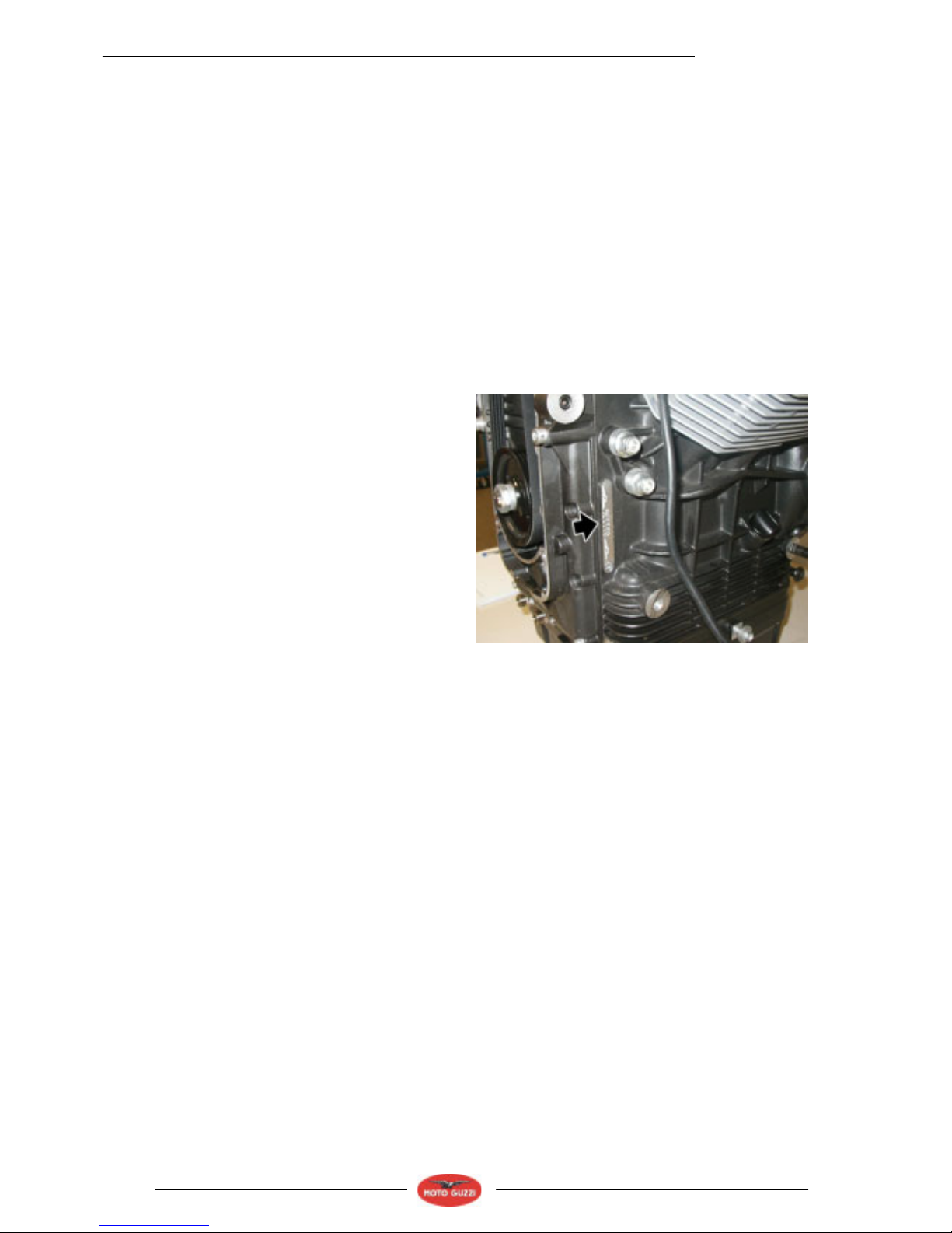
1.5. POSITION OF THE SERIAL NUMBERS
1.5.1. POSITION OF THE SERIAL NUMBERS
These numbers are necessary for vehicle registration.
NOTE Altering the vehicle's identification numbers is
punishable by law with heavy fines and penalties. Altering
the frame number voids the warranty.
ENGINE NUMBER
The engine number is stamped on the left-hand side, next to
the engine oil level plug.

TECHNICAL INFORMATION
2-1
Engine V1100
TECHNICAL INFORMATION 2

TECHNICAL INFORMATION
2 - 2
Engine V1100
TABLE OF CONTENT
2.1. TECHNICAL INFORMATION............................................................................................................................ 3
2.1.1. TECHNICAL DATA.................................................................................................................................... 3
2.1.2. LUBRICANT TABLE .................................................................................................................................. 4
2.1.3. TIGHTENING TORQUES.......................................................................................................................... 5
2.1.4. SPECIAL TOOLS ...................................................................................................................................... 7
TECHNICAL INFORMATION
2-3
Engine V1100
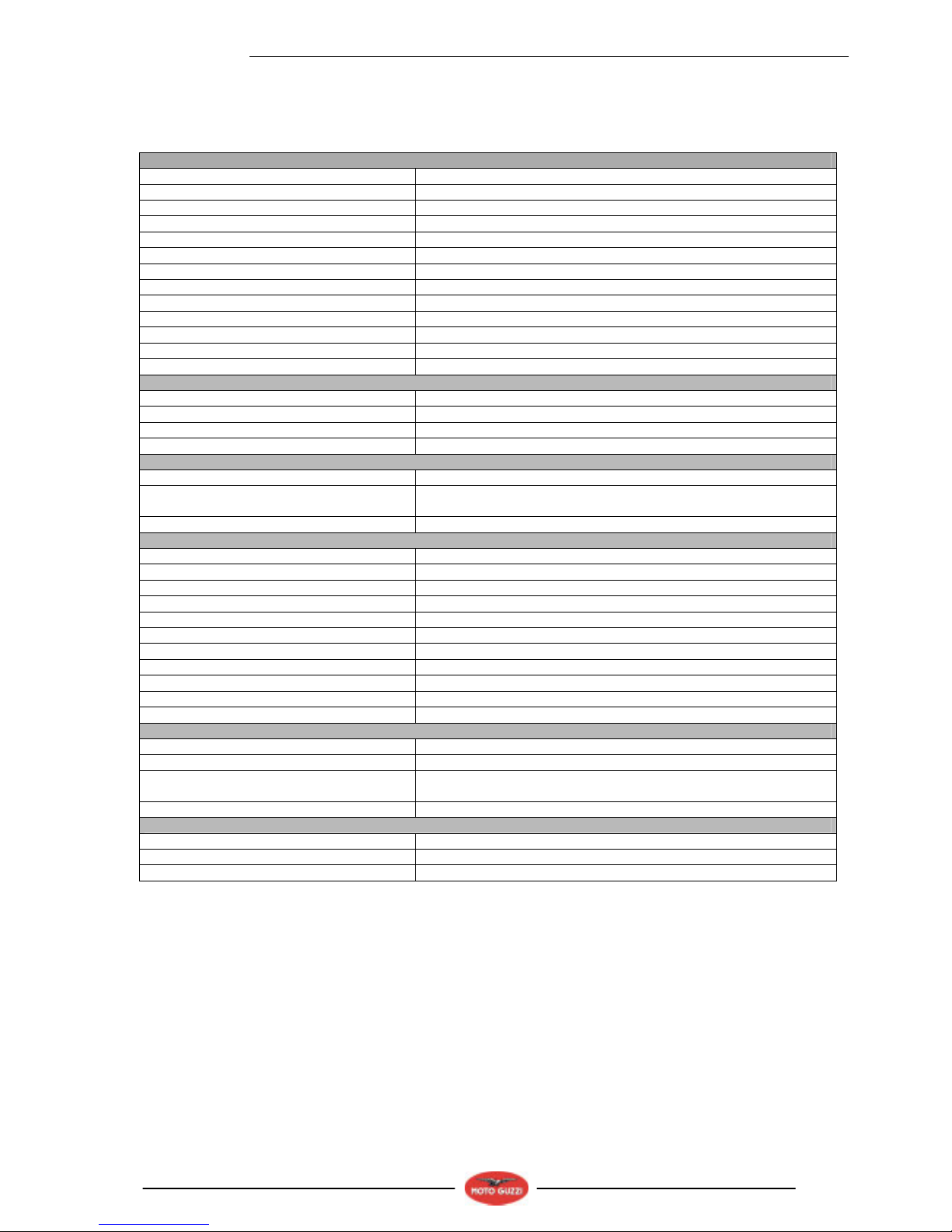
2.1. TECHNICAL INFORMATION
2.1.1. TECHNICAL DATA
ENGINE
Type twin-cylinder, 90° V transversal, 4-stroke engine
Number of cylinders two
Cylinder arrangement V, 90°
Total displacement 1064 cm3 (65 in3)
Bore/Stroke 92 x 80 mm (3.6 x 3.1 in).
Compression ratio 9.6 : 1
Starting electric
Engine idling speed 1100 ± 100 rpm
Clutch single plate, dry clutch with cush drive damper
Lubricating system System under pressure, adjustment by valves and vane pump
Air filter cartridge, dry
Cooling system air cooled
CAPACITIES
Engine oil Engine oil and oil filter change 3600 cm3 (219 in3)
Gearbox fluid 500 cm3 (30.5 in3)
Transmission fluid 380 cm3 (23.2 in3)
TIMING SYSTEM
Timing diagram: 2 valves, with rods and rocker arms
Values with inspection clearance between
rocker arms and valve
intake 0.10 mm (0.0039 in.)
exhaust 0.15 mm (0.0059 in.)
TRANSMISSION SYSTEM
primary drive gear, ratio: 26/35 = 1:1.3461
gearbox Mechanic, with 6 speeds, controlled by a pedal on engine left side
overall gear ratios:
1st gear 17/38 = 1:2.2353
2nd gear 20/34 = 1:1.7
3rd gear 23/31 = 1:1.3478
4th gear 26/29 = 1:1.1154
5th gear 31/30 = 1:0.9677
final drive with cardan joint
ratio 12/44 = 1:3.6667
FUEL SYSTEM
Type Electronic injection (Weber – Marelli) with stepper motor
Choke Ø 36 mm (1.417 in.)
Fuel Premium grade unleaded fuel, minimum octane rating 95 (RON) and
85 (MON).
SPARK PLUGS
Internal (long life) NGK PMR8B
External NGK BPR6ES
Electrode gap 0.6 – 0.7 mm (0.024 – 0.028 in.)
TECHNICAL INFORMATION
2 - 4
Engine V1100
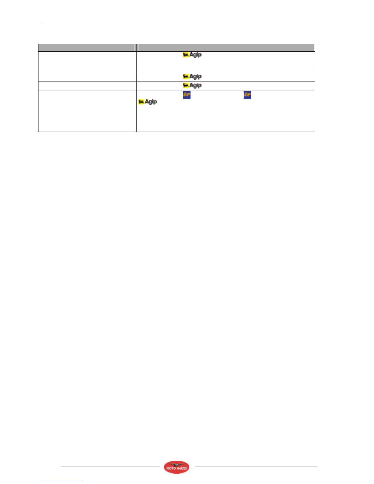
2.1.2. LUBRICANT TABLE
LUBRICANT PRODUCT
Engine oil
RECOMMENDED: RACING 4T 5 W 40
As an alternative to recommended oils, top brand oils meeting or exceeding
CCMC G-4 A.P.I. SG specifications can be used.
Transmission fluid
RECOMMENDED: TRUCK GEAR 80 W 90
Gearbox fluid
RECOMMENDED: ROTRA MP/S 85 W 90
Bearings and other
lubrication points
RECOMMENDED:
BIMOL GREASE 481, AUTOGREASE MP or
GREASE SM2.
As an alternative to recommended grease, use top brand rolling bearing
grease that will resist a temperature range of -30°C to +140°C (-22°F to
+284°F), with dripping point 150°C to 230°C (302°F to 446°F), high
corrosion protection, good resistance to water and oxidization.
TECHNICAL INFORMATION
2-5
Engine V1100
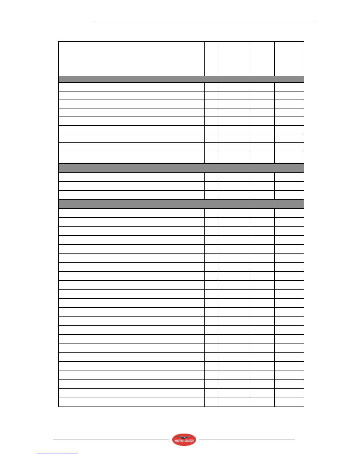
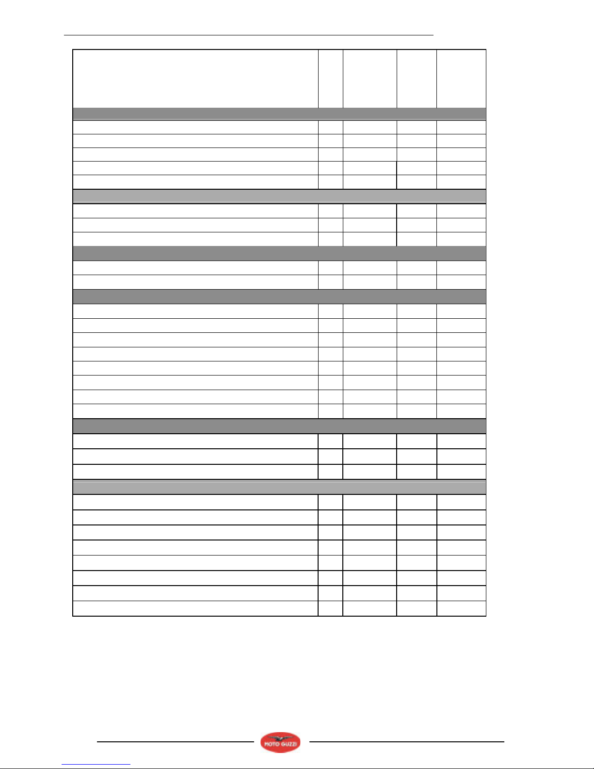
2.1.3. TIGHTENING TORQUES
DESCRIPTION
QUANTITY
SCREW / NUT
TIGHTENING
TORQUE
(Nm)
Note
HEAD UNIT
head taper cap 6 4
stud bolt M8x42 4 M8 35
adjuster 4 / / /
Nut 4 8-11
Hex.head screw DA M6x16 4 M6 6-8
stainl.st. TBEI screw M6x25 16 M6 10
stainl.st.flanged TBEI screw M5x16 4 M5 6-7
oil/head temperature sensor M12x1.5 1 M12 10-12
head temperature sensor casing M10x1.5 1 M10 10-12
TIMING UNIT
Hex.head screw DA M6x20 3 M6 8-12
nut M18x1.5 1 M18 150
belt tension 50
LOCKS
stud bolt M10x35 2 M10 40
Linkage 1 42
nut EA ZB M10x1.5 2 M10 40-42
head bolt 1 40-42
stud bolt M8x75 2 M8 35
stud bolt M8x66 1 M8 35
Hex.head screw DA M8x25 2 M8 25
Flathead Allen screw M4x8 UNI 5933 1 M4 5
TCEI screw M4x10 2 M4 5
Hex.head screw DA M8x25 1 M8 25
TCEI screw DA M6x30 2 M6 8-12
TCEI screw DA M8x55 cl. 8.8 UNI 5931 dacromet 1 M8 23
TCEI screw M6x16 2 M6 8-12
TCEI screw DA M6x30 1 M6 8-12
TCEI screw DA M6x40 2 M6 8-12
TCEI screw DA M6x60 1 M6 8-12
fitting M24x1.5 2 M24 40
TCEI screw DA M6x55 1 M6 8-12
TCEI screw DA M6x20 2 M6 8-12
copper line nipples M18x1.5 1 M18 20
plug with rod 2 / / /
magnetic plug M10x1.5 1 M10 20
TECHNICAL INFORMATION
2 - 6
Engine V1100
DESCRIPTION
QUANTITY
SCREW / NUT
TIGHTENING
TORQUE
(Nm)
Note
LUBRICATION UNIT
TCEI screw DA M8x30
4 M8 25
drilled screw M8x1.25
1 M8 15-18
plug M18x1.5
1 M18 40
plug M32x1.5
1 M32 40
CRANKSHAFT UNIT
connecting rod screw 2 60-62
nut EBFM ZB MF25x1.5 1 M25 120
FRAME UNIT ON ENGINE
TCEI screw DA M6x40
2 M6 8-12
reduction
4 20
IGNITION UNIT
TCEI screw DA M8x45
1 M8 22
TCEI screw DA M10x60
1 M10 see nut
nut M10x1.5 flanged
1 M10 30
TBEI screw DA M8x50
1 M8 / / /
nut EBFM DA MF16x1.5
1 M16 80
spark plug NGK BPR 6ES
2 20-30
spark plug PMR8b
2 13-15
TCEI screw M6x16
4 M6 8-12
FUEL FEED CONTROL UNIT
TCEI screw M5x12
2 M5 6-7
stainl.st.flanged TBEI screw M5x16
2 M5 6-7
TCEI screw DA M6x25
6 M6 8-12
GEAR SHIFT UNIT
Screws securing clutch housing to gearbox
14 M6 13
Screws securing bearing to clutch housing
3 M6 10
Clutch housing stop screws
1 M8 24
Ring nut on clutch shaft
1 M22x1 100
Neutral sensor on gearbox
1 M8x1 10
Magnetic plug
1 M10 24
Oil filler cap
1 M18x1.5 28
Union for breather hose
1 M10 8
TECHNICAL INFORMATION
2-7
Engine V1100
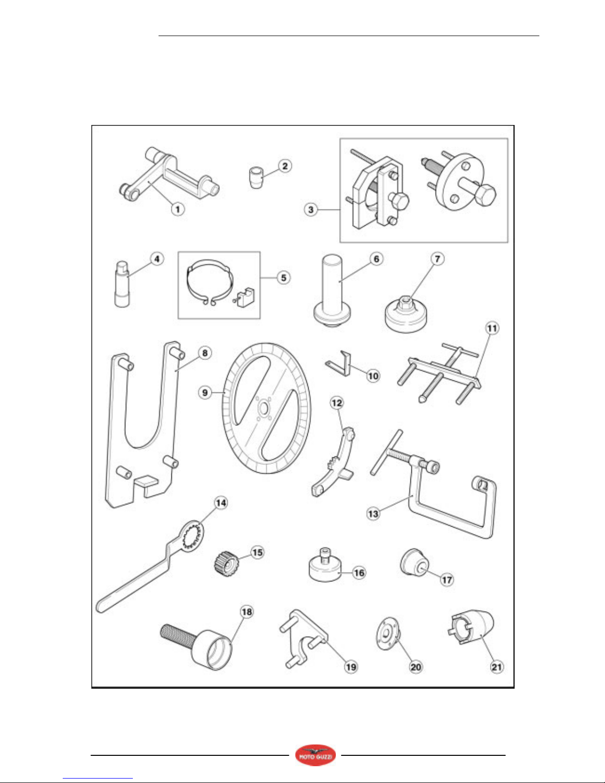
2.1.4. SPECIAL TOOLS
Suitable special tools are necessary for correctly removing, refitting and adjusting.
Unsuitable tools and/or improvised procedures could cause damage that might be avoided if the special tools are used.
Following are the special tools designed specifically for this vehicle.
If necessary, request the general special tools.
TECHNICAL INFORMATION
2 - 8
Engine V1100
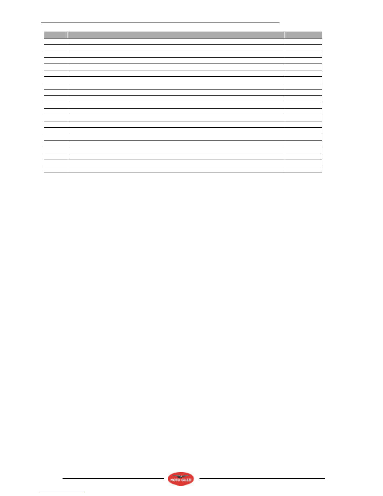
Pos. Description Part no.
1 Belt tensioning tool 05.94.86.30
2 Front cover installation cone 05.91.17.30
3 Gearbox opening tool 05.91.25.30
4 Tool for removing internal spark plug 05.90.19.30
5 Piston ring compression tool 05.92.80.30
6 Timing cover seal drift 05.92.72.30
7 Wrench for removing cover on sump and filter 01.92.91.00
8 Support for gearbox 14.92.96.00
9 Degree wheel for checking timing 19.92.96.00
10 Index for checking timing 17.94.75.60
11 Tool for removing flange on flywheel side 12.91.36.00
12 Tool for locking flywheel and starter gear 12.91.18.01
13 Tool for removing and installing valves 10.90.72.00
14 Tool for locking clutch body 30.91.28.10
15 Clutch installing tool 30.90.65.10
16 Tool for installing seal on flywheel-side flange 14.92.71.00
17 Tool for assembling flywheel-side flange with seal onto crankshaft 12.91.20.00
18 Tool for installing seal on flywheel-side flange 19.92.71.00
19 Tool for retaining camshaft gear 14.92.73.00
20 Hub for degree wheel 65.92.84.00
21 Tool for removing clutch hub 05.91.26.30

ENGINE
3 - 1
Engine V1100
ENGINE 3

ENGINE
3 - 2
Engine V1100
TABLE OF CONTENTS
3.1. REMOVING THE ACCESSORIES ................................................................................................................... 3
3.1.1. REMOVING THE STARTER MOTOR ....................................................................................................... 3
3.1.2. REMOVING THE BLOW-BY SYSTEM...................................................................................................... 4
3.2. GENERATOR ................................................................................................................................................... 6
3.2.1. REMOVING THE GENERATOR ............................................................................................................... 6
3.2.2. INSTALLATION ....................................................................................................................................... 10
3.3. TIMING SYSTEM............................................................................................................................................ 14
3.3.1. REMOVAL AND INSTALLATION ............................................................................................................ 14
3.3.2. TECHNICAL DATA.................................................................................................................................. 18
3.3.3. TIMING .................................................................................................................................................... 19
3.3.4. MEASURING THE SENSOR GAP .......................................................................................................... 21
3.4. OIL PUMP....................................................................................................................................................... 23
3.4.1. REMOVING THE OIL PUMP ................................................................................................................... 23
3.5. HEADS ........................................................................................................................................................... 24
3.5.1. REMOVING THE HEAD COVERS .......................................................................................................... 24
3.5.2. REMOVING THE HEADS........................................................................................................................ 25
3.5.3. CHECKING THE COMPONENTS ........................................................................................................... 30
3.5.4. REASSEMBLING THE HEADS ............................................................................................................... 32
3.6. CYLINDERS AND PISTONS .......................................................................................................................... 37
3.6.1. REMOVAL, CHECK AND INSTALLATION.............................................................................................. 37
3.7. FLYWHEEL..................................................................................................................................................... 42
3.7.1. REMOVAL, CHECK AND REASSEMBLY ............................................................................................... 42
3.8. CRANKSHAFT AND CONNECTING RODS................................................................................................... 44
3.8.1. REMOVAL ............................................................................................................................................... 44
3.8.2. CHECK .................................................................................................................................................... 46
3.8.3. REASSEMBLY ........................................................................................................................................ 49
3.9. OIL SUMP....................................................................................................................................................... 50
3.9.1. REMOVAL, CHECK AND REASSEMBLY ............................................................................................... 50

ENGINE
3 - 3
Engine V1100
3.1. REMOVING THE ACCESSORIES
3.1.1. REMOVING THE STARTER MOTOR
• Loosen and remove the two screws and set aside the
washers.
• Slide out the starter motor.
 Loading...