

MOTO GUZZI Daytona RS, V10 Centauro, 1100 Sport, SPORT 1100 Workshop Manual


MOTO GUZZI S.p.A.
TECHNICAL PUBBLICATIONS / TECHNISCHE VERÖFFENTLICHUNGEN / TECHNISCHE UITGAVEN
Cod. 37 92 01 05
Printed in Italy - D.E.Ca. - Ravenna 1000 K - 05/95
The contents of this Manual is not binding and Moto Guzzi reserves the right to make alterations, if and when
required, of components, accessories, tooling, etc. which are deemed expendient for the purpose of
improvement or, for any technical-commercial requirement, or in order to comply with law provision in the
different countries, without however undertaking to promptly up-date this Manual
Der Inhalt dieses Handbuchs ist unverbindlich. Moto Guzzi behält sich daher das Recht vor, Änderungen
an Teilen, Zubehörteilen, Ausrüstungen usw. anzubringen, falls sich diese als notwendig erweisen sollten,
um Verbesserungen auszuführen, technischen bzw. verkaufstechnischen Ansprüchen nachzukommen
order um die Kriterien der Gesetzgebungen der einzelnen Länder zu erfüllen, ohne daß das Handbuch
umgehend überarbeitet werden muß.
De inhoud van dit handboek is niet bindend en de firma GUZZI behoudt zich dan ook het recht voor, indien
dit nodig mocht zijn, om door haar wenselijk geachte wijzigingen aan onderdelen, accessoires, hulpstukken
e.d. aan te brengen teneinde naar verbetering van de producten te streven of naar aanleiding van welke
noodzaak van technische of commerciële aard dan ook of met het oog op aanpassing aan de wettelijke eisen
van de verschillende landen zonder echter verplicht te zijn dit handboek tijdig te updaten.
INTRODUCTION
Purpose of this manual is to give the necessary instructions for overhauling and carrying out repairs in a rational way.
All data herein contained are meant to give a general knowledge of the main checking operations to be done when overhauling
the different component groups.
To this end, the manual contains many illustrations, drawings, diagrams, and tables to assist you in the stripping, checking,
and assembling operations.
This manual will also be a guidance for anybody who wishes to familiarize with the manufacturing characteristics of the various
component parts of this model.
The knowledge of these will be an essential factor for performing a good job.
EINFÜHRUNG
Dieses Handbuch soll die notwendigen Anlagen zur Durchführung von Überholungen und Reparaturen vermitteln.
Die im Handbuch enthaltenen Daten geben auch einen allgemeinen Überblick darüber, welche Kontrollen beim Überholen
der einzelnen Baugruppen durchzuführen sind.
Bilder, Zeichnungen und Diagramme; die für den Abbau, Kontrolle und Montage erforderlich sind, vervollstuandigen die
Angaben.
Dieses Handbuch ist ebenso ein Leitfaden für den Kunden, die die Herstellungsdaten und Toleranzen der einzelnen Teile
wissen möchte.
Für das Werkstattpersonal ist die Kenntnis dieser Daten eine Voraußetzung zur Durchfuuhrung sauberer Arbeiten.
VOORWOORD
Het doel van dit handboek is de nodige aanwijzingen te verstrekken om revisies en reparaties op rationele wijze uit te kunnen voeren.
De opgenomen gegevens dienen om een algemeen inzicht te krijgen in de belangrijkste controles die tijdens de revisie van
de diverse onderdelen verricht moeten worden.
Om de diverse onderdelen makkelijker te kunnen demonteren, controleren en monteren zijn de nodige afbeeldingen,
tekeningen en schema’s in dit handboek opgenomen.
Dit handboek dient ook als leidraad voor diegenen die de constructieonderdelen van de motorfiets die in dit handboek aan
de orde komt willen leren kennen: kennis van deze onderdelen door het personeel dat met de reparaties belast is, is een
essentiële factor voor de juiste uitvoering van de reparatiewerkzaamheden.
IMPORTANT
The text is supplemented with schematic illustrations for quick reference and better understanding of the subjects concerned.
This manual contains some special remarks:
Accident prevention rules for the mechanic and for the personnel working nearby.
Possibility of damaging the motorcycle and/or its components.
Additional information concerning the job being carried out.
WICHTIG
Zum schnelleren Verständnis wurden die verschiedenen Paragraphen durch Abbildungen vervollständigt, die das behandelte Argument in der Vordergrund stellen. Dieses Handbuch enthält Informationen von besonderer Bedeutung:
Unfallverhütungsnormen für die am Motorrad arbeitende und die in der Nähe arbeitenden Personen.
Es besteht die Möglichkeit das Motorrad und/oder seine Bestandteile zu beschädigen.
Weitere Informationen für den laufenden Arbeitsvorgang.
BELANGRIJK
Om een snel begrip van de tekst te krijgen staan er schematische illustraties bij de diverse paragrafen die het onderwerp dat
daarin behandeld wordt laten zien. In dit handboek zijn ter informatie opmerkingen opgenomen die een bijzondere betekenis
hebben.
Veiligheidsvoorschriften voor degene die aan de motor werkt of die daar in de buurt van werkt.
De mogelijkheid bestaat dat de motorfiets en/of de onderdelen ervan beschadigd worden.
Nadere informatie over de handeling die op dat moment beschreven wordt.
NOTE The terms “right” and “left” in the text are to be considered as seen by the rider astride the machine.
ANM. In der Beschreibung erwähntes “Links” oder “Rechts” bedeuten immer in Fahrtrichtung gesehen.
OPMERKING Met “rechts” of “links” wordt de kant bedoeld vanaf de berijdersplaats gezien.


3
INDEX
1 IDENTIFICATION DATA ............................................................................................................... 6
1.1 Spare Parts .................................................................................................................................... 6
2 GENERAL FEATURES ................................................................................................................. 7
3 INSTRUMENTS AND CONTROLS ............................................................................................... 11
3.1 Control panel ................................................................................................................................. 11
3.2 Light switches ................................................................................................................................ 12
3.2.1 Switch, hazard warning lights ........................................................................................................ 12
3.3 Horn Button, Headlamp Flasher and direction indicators .............................................................. 12
3.4 «Choke» control............................................................................................................................. 12
3.5 Clutch lever .................................................................................................................................... 13
3.6 Starter Button and Engine Stop Switch ......................................................................................... 13
3.7 Throttle twist grip ........................................................................................................................... 13
3.8 Brake lever, front brake ................................................................................................................. 13
3.9 Brake pedal for rear brake ............................................................................................................. 13
3.10 Gearbox control pedal ................................................................................................................... 13
3.11 Fuel filler cap ................................................................................................................................. 14
3.12 Fuel tap .......................................................................................................................................... 14
3.13 Electric fuel cock ............................................................................................................................ 14
3.14 Fuse box ........................................................................................................................................ 15
3.15 Steering damper ............................................................................................................................ 15
3.16 Documents and objects holder ...................................................................................................... 16
3.17 Helmet holder ................................................................................................................................ 16
3.18 Motorbike lateral supporting arm ................................................................................................... 16
3.18.1 Side stand for motorcycle support with safety switch .................................................................... 17
3.19 Driver seat removal (DAYTONA RS and SPORT 1100 I) ............................................................. 17
3.20 Removing the saddle (V10 CENTAURO) ...................................................................................... 17
3.21 Passenger holding belt (V10 CENTAURO) ................................................................................... 18
4 LUBRICATION .............................................................................................................................. 19
4.1 Engine lubrication .......................................................................................................................... 19
4.2 Changing the filter cartridge and cleaning the mesh filter.............................................................. 19
4.3 Gearbox lubrication........................................................................................................................ 20
4.4 Rear transmission box lubrication.................................................................................................. 20
4.5 Greasing the driving shaft .............................................................................................................. 21
4.6 Front fork oil change ...................................................................................................................... 21
4.7 Greasing ........................................................................................................................................ 21
5 MAINTENANCE AND ADJUSTMENTS ....................................................................................... 22
5.1 Adjusting the clutch lever ............................................................................................................... 22
5.2 Adjusting the front brake lever ....................................................................................................... 22
5.3 Rear brake pedal adjustment......................................................................................................... 23
5.4 Adjusting the steering ................................................................................................................... 23
5.5 Adjustment of telescopic fork ......................................................................................................... 24
5.6 Rear suspension adjustment ......................................................................................................... 24
5.7 Changing the air filter..................................................................................................................... 26
5.7.1 Changing the air filter (V10 CENTAURO)..................................................................................... 27
5.8 Tappet clearance checking ............................................................................................................ 28
5.8.1 Timing belts (DAYTONA RS and V10 CENTAURO) ..................................................................... 28

4
5.9 Adjusting the headlight beam ........................................................................................................ 28
5.10 Cleaning the windscreen ............................................................................................................... 29
5.11 Motor washing rules....................................................................................................................... 29
6 SERVICE SCHEDULE .................................................................................................................. 30
7 TORQUE WRENCH SETTINGS ................................................................................................... 31
7.1 SPORT 1100 I ............................................................................................................................... 31
7.2 DAYTONA V10 CENTAURO ......................................................................................................... 32
8 SPECIFIC EQUIPMENT ................................................................................................................ 34
8.1 Specific equipment (DAYTONA RS and V10 CENTAURO) .......................................................... 36
9 REMOVING THE PROPULSOR UNIT FROM THE FRAME ........................................................ 38
9.1 V10 CENTAURO ........................................................................................................................... 39
9.2 SPORT 1100 I AND DAYTONA RS .............................................................................................. 40
10 ENGINE UNIT ................................................................................................................................ 42
10.1 Dismantling the engine assembly .................................................................................................. 42
10.1.1 Engine reassembly ........................................................................................................................ 50
10.1.2 Timing system phase-setting check ................................................................................................ 54
10.2 Checks ........................................................................................................................................... 55
11 ENGINE UNIT (DAYTONA RS AND V10 CENTAURO) ............................................................... 70
11.1 Engine dismantling ........................................................................................................................ 70
11.2 Engine reassembly ........................................................................................................................ 78
11.3 Engine timing ................................................................................................................................. 82
11.4 Checks ........................................................................................................................................... 87
12 WEBER INJECTION-IGNITION SYSTEM .................................................................................... 102
12.1 System components ...................................................................................................................... 102
12.2 Operation phases .......................................................................................................................... 102
12.3 Fuel circuit ..................................................................................................................................... 105
12.4 Air circuit ........................................................................................................................................ 106
12.5 Electric circuit ................................................................................................................................. 107
12.6 Calibration rules for carburation and regulation of the engine ....................................................... 111
12.7 TRIMMER operation on the electronic control unit type IAW 16M for CO regulation .................... 112
12.8 Starter lever adjustment................................................................................................................. 113
12.9 Adjustment of the starter RPM....................................................................................................... 113
12.10 Induction system control ................................................................................................................ 113
12.11 Use of the check lamp for the defects detection............................................................................ 114
12.12 Reset procedure for the electronic control unit IAW 16M .............................................................. 118
12.13 Spark plugs.................................................................................................................................... 118
12.14 Evaporative emission control system ............................................................................................ 119
13 CLUTCH ........................................................................................................................................ 122

5
14 GEARBOX..................................................................................................................................... 123
14.1 Gearbox lubrication........................................................................................................................ 124
14.2 Disassembly .................................................................................................................................. 124
14.3 Reassembly ................................................................................................................................... 129
15 REAR DRIVE................................................................................................................................. 131
15.1 Rear drive box lubrication .............................................................................................................. 132
15.2 Drive box disassembly ................................................................................................................... 132
15.3 Reassembly ................................................................................................................................... 134
15.4 Transmission shaft......................................................................................................................... 136
16 FRAME .......................................................................................................................................... 137
17 FRONT FORK ............................................................................................................................... 142
17.1 Change the fork oil......................................................................................................................... 142
17.2 Disassemble fork stem .................................................................................................................. 142
17.3 Removal of the screwed cap ......................................................................................................... 142
17.4 Oil draining..................................................................................................................................... 144
17.5 Cartridge disassembly ................................................................................................................... 144
17.6 Oil refilling ...................................................................................................................................... 145
17.7 Substituting the oil retainer bushing............................................................................................... 146
18 REAR SUSPENSION .................................................................................................................... 150
19 WHEELS ....................................................................................................................................... 152
19.1 Front wheel .................................................................................................................................... 152
19.2 Rear wheel..................................................................................................................................... 153
19.3 Tyres .............................................................................................................................................. 154
20 BRAKE SYSTEM .......................................................................................................................... 155
20.1 Checking brake pads wear ............................................................................................................ 157
20.2 Checking the brake fluid in the master cylinder reservoir .............................................................. 157
20.3 Checking brake disks..................................................................................................................... 158
20.4 Air bleeding from braking circuit .................................................................................................... 161
21 ELECTRICAL EQUIPMENT.......................................................................................................... 163
21.1 Battery ........................................................................................................................................... 163
21.2 Alternator and voltage controller....... ............................................................................................. 164
21.3 Starter motor .................................................................................................................................. 166
21.4 Lighting equipment ........................................................................................................................ 167
21.4.1 Replacing bulbs (DAYTONA RS and SPORT 1100 I) ................................................................... 167
21.4.2 Replacing bulbs (V10 VENTAURO) .............................................................................................. 168
21.5 Key to wiring diagram (DAYTONA RS and SPORT 1100 I) .......................................................... 170
21.6 Key to wiring diagram (V10 VENTAURO) ..................................................................................... 171
6
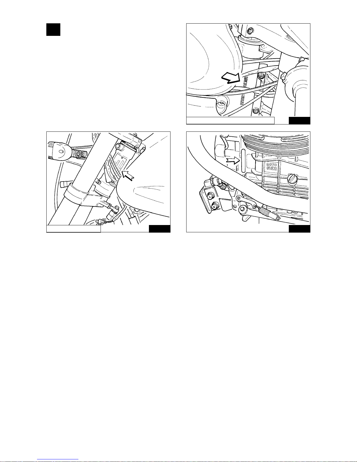
1 IDENTIFICATION DATA
(Fig. 01-01 / 01-02 / 01-03)
Every motorcycle is stamped with identification
numbers on the tubular frame and on the crankcase.
The frame number is written in the motorcycle logbook
and is the vehicle’s legal identification.
01-01
DAYTONA RS / SPORT 1100 I
1.1 SPARE PARTS
Only «Original MOTO GUZZI Spare Parts» should be used.
The use of non-original parts invalidates the warranty.
01-02 01-03
V10 CENTAURO

7
2 GENERAL FEATURES
ENGINE (SPORT 1100 I)
4-stroke, twin cylinder
Cylinder configuration: .......................................................................................................................90° V-twin
Bore:......................................................................................................................................................... 92mm
Stroke:..................................................................................................................................................... 80 mm
Displacement: ....................................................................................................................................... 1064 cc
Compression ratio: ................................................................................................................................... 10,5:1
Max. torque: ........................................................................................................ 97 Nm (9,9 kgm) at 6000 rpm
Max. power: ............................................................................................................66 KW (90 CV) at 7800 rpm
ENGINE (V10 CENTAURO AND DAYTONA RS)
NOTE: The data in parenthesis [ ] apply to model DAYTONA RS only.
4-stroke, twin cylinder
Cylinder configuration: .......................................................................................................................90° V-twin
Bore:......................................................................................................................................................... 90mm
Stroke:..................................................................................................................................................... 78 mm
Displacement: ......................................................................................................................................... 992 cc
Compression ratio: ................................................................................................................................... 10,5:1
Max. torque: ............................................................................................. 88 Nm (9,0 kgm) at 5800 [7800] rpm
Max. power:......................................................... 70 KW (95 CV) at 8200 rpm [ 75 KW (102 CV) at 8400 rpm]
VALVE GEAR (SPORT 1100 I)
With rods and rockers and 2 valves per cylinder. One camshaft in the crankcase driven by duplex chain with
automatic chain tensioner. The timing data (referring to the 1 mm lift of the tappets) are as follows:
Intake:
open 22° before TDC
close 54° after BDC
Exhaust:
open 52° before BDC
close 24° after TDC
Functioning clearance with a cold engine:
intake valves 0.10 mm
exhaust valves 0.15 mm
VALVE GEAR (V10 CENTAURO and Mod. DAYTONA RS with specifications for USA, SWITZERLAND and
SINGAPORE)
Overhead camshaft with 4 valves per cylinder. Straight-tooth gear control, in light alloy and positive drive belt.
The timing data (referring to the 1 mm lift of the tappets) are as follows:
Intake:
open 22°30' before TDC
close 57°30' after BDC
Exhaust:
open 49°30' before BDC
close 12°30' after TDC
Functioning clearance with a cold engine:
intake valves 0.10 mm
exhaust valves 0.15 mm
VALVE GEAR (DAYTONA RS - Model with specifications for USA, SWITZERLAND and SINGAPORE
excluded)
Overhead camshaft with 4 valves per cylinder. Straight-tooth gear control, in light alloy and positive drive belt.
The timing data (referring to the 1 mm lift of the tappets) are as follows:
Intake:
open 22°30' before TDC
close 69°30' after BDC
Exhaust:
open 63°30' before BDC
close 28°30' after TDC
Functioning clearance with a cold engine:
intake valves 0.10 mm
exhaust valves 0.15 mm

8
Lubrication
NOTE: The data in parenthesis [ ] apply to models DAYTONA RS and V10 CENTAURO.
Pressure fed by gear pump.
Oil filters: wire mesh inside sump and replaceable cartridge filter outside sump.
Normal lubrication pressure 3.8÷4.2 [5] kg/cm2, pressure valve, thermostat and cooler.
Low oil pressure sensor (electrical) on crankcase.
GENERATOR / ALTERNATOR
On front of crankshaft (14V - 25A).
IGNITION
“WEBER MARELLI” electronic digital induced discharge, with high-efficiency coil.
Spark plugs:
SPORT 1100I: NGK BPR 6 ES
DAYTONA RS
NGK DR9 EA
V10 CENTAURO
STARTING
Electric starter (12V-1,2 kW) with solenoid engagement. Ring gear bolted on flywheel.
Starter button (START) « » on right of handlebars.
TRANSMISSION DATA
Clutch
Twin driven plates, dry type, on flywheel. Hand controlled by lever on left of handlebars.
Primary drive
By gears, ratio: 1 to 1.3529 (tooth ratio 17/23).
By gears, ratio: 1 to 1.235 (tooth ratio 17/21). (Switzerland version only for model V10 CENTAURO)
GEARBOX
5-speed, with constantly meshed gears with front dog clutch. Incorporated cush drive.
Pedal operated on the left side of the motorcycle.
NOTE: The SPORT 1100 I and DAYTONA RS models up to gearbox No. CF011499 and CL011199 have
been provided with straight teeth; from the gearbox No. CF11400 and CL011200 they have been provided
with helical teeth.
The V10 CENTAURO model has a gearbox provided with helical tooth gears.
Gear ratios (DAYTONA RS and SPORT 1100 I):
Low gear = 1 to 1,8125 (tooth ratio 16/29)
2nd gear = 1 to 1,2500 (tooth ratio 20/25)
3rd gear = 1 to 1 (tooth ratio 23/23)
4th gear = 1 to 0,8333 (tooth ratio 24/20)
5th gear = 1 to 0,7308 (tooth ratio 26/19)
Gear ratios (V10 CENTAURO):
Low gear = 1 to 2 (tooth ratio 14/28)
2nd gear = 1 to 1,3158 (tooth ratio 19/25)
3rd gear = 1 to 1 (tooth ratio 23/23)
4th gear = 1 to 0,8462 (tooth ratio 26/22)
5th gear = 1 to 0,7692 (tooth ratio 26/20)
}
Gear ratios (V10 CENTAURO Switzerland version):
Low gear = 1 to 2 (tooth ratio 14/28)
2nd gear = 1 to 1,3889 (tooth ratio 18/25)
3rd gear = 1 to 1,0476 (tooth ratio 21/22)
4th gear = 1 to 0,8696 (tooth ratio 23/20)
5th gear = 1 to 0,7500 (tooth ratio 28/21)
Secondary transmission
Shaft with universal joint and gears.
Ratio: 1:4,125 (tooth ratio 8/33)
Overall gear ratios (Engine-wheel) (DAYTONA RS and SPORT 1100 I):
Low gear = 1 to 10,1153
2nd gear = 1 to 6,9761
3rd gear = 1 to 5,5809
4th gear = 1 to 4,6507
5th gear = 1 to 4,0783

9
Overall gear ratios (Engine-wheel) (V10 CENTAURO): Overall gear ratios (Engine-wheel)
(V10 CENTAURO) Switzerland version:
Low gear = 1 to 11,1618 Low gear = 1 to 10,1912
2nd gear = 1 to 7,3433 2nd gear = 1 to 7,0772
3rd gear = 1 to 5,5809 3rd gear = 1 to 5,3382
4th gear = 1 to 4,7223 4th gear = 1 to 4,4309
5th gear = 1 to 4,2930 5th gear = 1 to 3,8217
FRAME
Rectangular section single-beam in NiCrMo steel. Semisupporting engine base.
SUSPENSIONS
Front: White Power upside-down hydraulic telescopic fork with individually adjustable rebound and compression;
Rear: steel swing arm with oval cross section. Single shock absorber White Power with separate adjustment of
spring preload and of hydraulic rebound and compression damping.
WHEELS
Light alloy castings with 3 hollow spokes (rear wheel with cush drive unit). Rim sizes:
– front: 3,50x17 MT H2
– rear: 4,50x17 MT H2
TYRES
NOTE: The data in parenthesis [ ] apply to models DAYTONA RS and V10 CENTAURO.
– front: 120/70 ZR 17
– rear: 160/70 ZR 17 [160/60 ZR 17]
Type: Tubeless
BRAKES
Front: two Brembo drilled semi-floating disc brakes in stainless steel for SPORT 1100 and V10 CENTAURO; [two
Brembo drilled floating discs, Racing type for DAYTONA RS] with fixed 4 differential piston calipers. Adjustable
manual control lever on the right side of the handle-bar;
– Ø disc 320 mm;
– Ø brake cylinder 34/30 mm;
– Ø master cylinder 16 mm.
Rear: stainless steel fixed disc brake with fixed double braking cylinder caliper. Brake pedal on centre-right of
motorbike;
– Ø disc 282 mm;
– Ø brake cylinder 32 mm;
– Ø master cylinder 11 mm.
DIMENSIONS AND WEIGHT (SPORT 1100 I AND DAYTONA RS)
NOTE: The data in parenthesis [ ] apply to models DAYTONA RS.
Wheelbase .................................................m 1,475
Overall length .............................................m 2,125
Overall width .............................................. m 0,720
Height......................................................... m 1,125
Ground clearance...........................m 0,160 [0,150]
Weight (dry)......................................... kg 221 [223]
DIMENSIONS AND WEIGHT (V10 CENTAURO)
Wheelbase .................................................m 1,475
Overall length .............................................m 2,180
Overall width .............................................. m 0,780
Height......................................................... m 1,094
Ground clearance.......................................m 0,154
Driver’s seat heigt ...................................... m 0,820
Weight (dry).................................................. kg 232
10
PERFORMANCE
Max. speed with one rider: 230 km/h for SPORT 1100 I (240 km/h for DAYTONA RS and 218 km/ h for V10
CENTAURO).
Fuel consumption: 4,5 lt/100 km (CUNA).
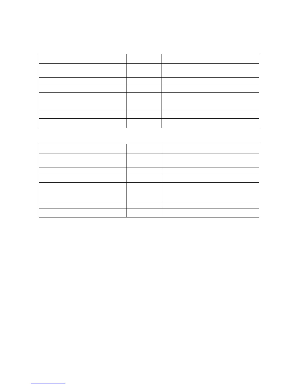
REFUELINGS (DAYTONA RS AND SPORT 1100 I)
Description Quantity Recommended products
Fuel tank 19 l Supergrade petrol (97 NO-RM/min.)
(reserve 3 l about) about Unleaded Petrol (95 NO-RM/min.)
Crankcase sump 3,500 l «Agip 4T Super Racing SAE 20W50» oil
Gearbox 0,750 l «Agip Rotra MP SAE 80 W/90» oil
Rear drive box 0,250
of which
(crown wheel and pinion lubrication) 0,230 «Agip Rotra MP SAE 80 W/90» oil
0,020 «Agip Rocol ASO/R» oil or «Molykote type A»
Front fork (each leg) 0,400 «WP suspension-REZ 71» oil (SAE 5)
Braking system (front and rear) — «Agip Brake Fluid - DOT 4» fluid
REFUELINGS (V10 CENTAURO)
Description Quantity Recommended products
Fuel tank 18 l Supergrade petrol (97 NO-RM/min.)
(reserve 5 l about) about Unleaded Petrol (95 NO-RM/min.)
Crankcase sump 3,500 l «Agip 4T Super Racing SAE 20W50» oil
Gearbox 0,750 l «Agip Rotra MP SAE 80 W/90» oil
Rear drive box 0,250
of which
(crown wheel and pinion lubrication) 0,230 «Agip Rotra MP SAE 80 W/90» oil
0,020 «Agip Rocol ASO/R» oil or «Molykote type A»
Front fork (each leg) 0,400 «WP suspension-REZ 71» oil (SAE 5)
Braking system (front and rear) — «Agip Brake Fluid - DOT 4» fluid
11
03-01 03-01
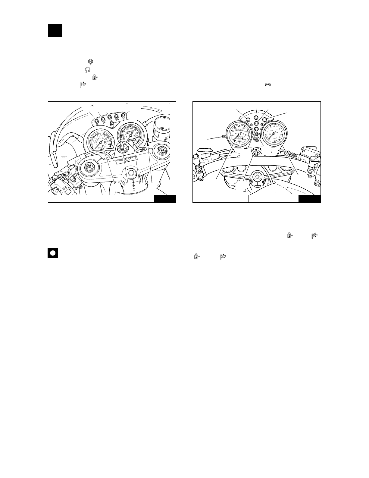
3 INSTRUMENTS AND CONTROLS
3.1 CONTROL PANEL (Fig. 03-01)
1 Key switch for devices and steering lock.
Position OFF «
» vehicle stationary. Key removable (no contact).
Position ON « » vehicle ready to be started. All circuits are on. Key not removable.
Position LOCK « » steering locked. Engine off, no contact, key removable.
Position P « » steering locked. Engine off; with switch «A» of Fig. 03-01 in position « » the parking light is
on. Key removable.
In order to use the steering lock mechanism, proceed as follows:
■ Turn the handlebars to the left.
■ Press the key downwards and release it, then turn it in an anticlockwise direction to the LOCK « » or P « »
position.
WARNING: Never turn the key to position LOCK « » or P « » when the engine is running.
2 Odometer, tachometer.
3 Rev counter.
4 Pilot light (green) «Neutral». Lights up when the gearbox is in neutral.
5 Pilot light (red) for generator current output. Should go out when the engine reaches a certain number of revs.
6 Petrol tank reserve pilot light (orange).
7 Pilot light (green) for flashing indicators.
8 Oil pressure pilot light (red). Goes out when the oil pressure is sufficient to ensure engine lubrication.
9 Pilot light (blue) for main beam.
10 Partial rev counter zeroing.
DAYTONA RS / SPORT 1100 I
V10 CENTAURO
5
4
6
8
9
7
3
1
2
10
10
9
7
8
4
6
5
1
2
3
12
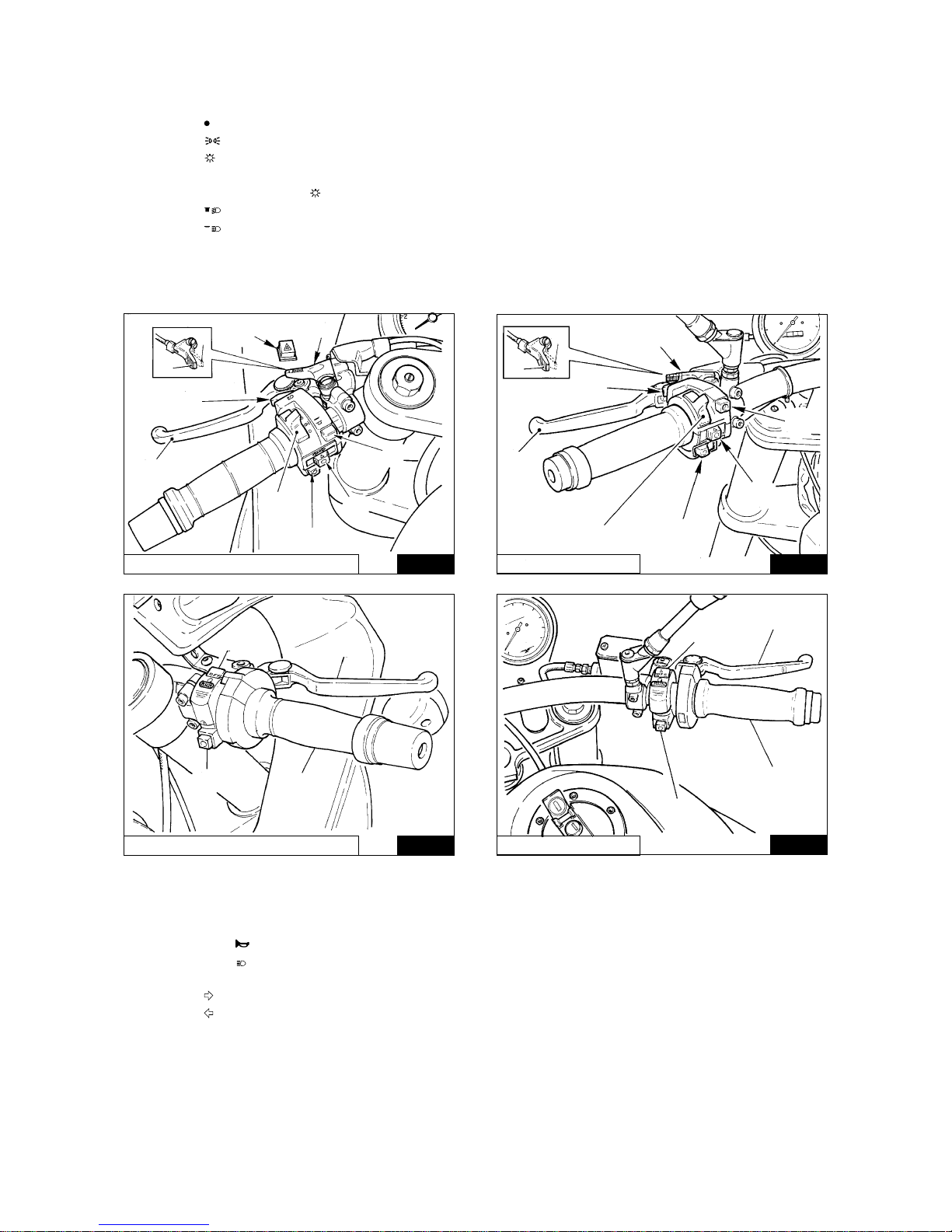
3.2 LIGHT SWITCHES (Fig. 03-02 / 03-03)
Are fitted to the sides of the handle-bars.
Switch «A»
■ Position « » lights off.
■ Position « » parking lights on.
■ Position « » twin-filament headlamp on.
Switch «B»
With switch «A» in position « ».
■ Position « » dipped beam.
■ Position « » main beam.
3.2.1 SWITCH, HAZARD WARNING LIGHTS («H» DI Fig. 03-02) (DAYTONA RS /SPORT 1100 I)
It is installed on the left hand side of the fairing and turns on both flashers at the same time.
03-02
03-02
03-03
03-03
DAYTONA RS / SPORT 1100 I
3.3 HORN BUTTON, HEADLAMP FLASHER AND DIRECTION INDICATORS (Fig. 03-02)
These are mounted on the left handlebar:
Push-button E « » sounds the electric horn when pressed.
Push-button C « » flashing light control.
Push-button «D» (turn).
■ Position « » for right turn signals control.
■ Position « » for left turn signals control.
■ Press the switch to disconnect flashers.
3.4 «CHOKE» CONTROL («F» IN Fig. 03-02)
The «CHOKE» is on the left handlebar and is used for cold starts.
■ Position «1» CHOKE on; starting position.
■ Position «2» CHOKE off; engine running.
V10 CENTAURO
V10 CENTAURO
DAYTONA RS / SPORT 1100 I
H
F
C
G
A
E
D
B
2
1
G
A
E
D
B
C
F
1
2
B
D
A
C
B
D
A
C
13
3.5 CLUTCH LEVER («G» IN Fig. 03-02)
This is on the left handlebar and is only to be used when starting or changing gear.
3.6 STARTER BUTTON AND ENGINE STOP SWITCH (Fig. 03-03)
These are mounted on the right handlebar.
With the key «1» in Fig. 03-01 in position ON « », the vehicle is ready for starting.
To start the engine:
■ check that switch «B» is in position (run);
■ pull the clutch lever in to disengage the clutch fully;
■ if the engine is cold, put the «CHOKE» control «F» in the starting position «1» (see Fig. 03-02).
■ press the starter button A «» (start).
To stop the engine in case of emergency:
■ turn the switch «B» to position (off).
Once the engine has stopped, turn the key switch Fig. 03-01 in position OFF « » remove the key from the switch.
NOTE: Before start, put switch «B» in (RUN) position.
3.7 THROTTLE TWIST GRIP («C» in Fig. 03-03)
The throttle control is on the right handlebar; turning the twist-grip towards the rider opens the throttle, turning
it away from the rider closes it.
3.8 BRAKE LEVER, FRONT BRAKE («D» in Fig. 03-03)
This is on the right handlebar and controls the master cylinder of the front brake.
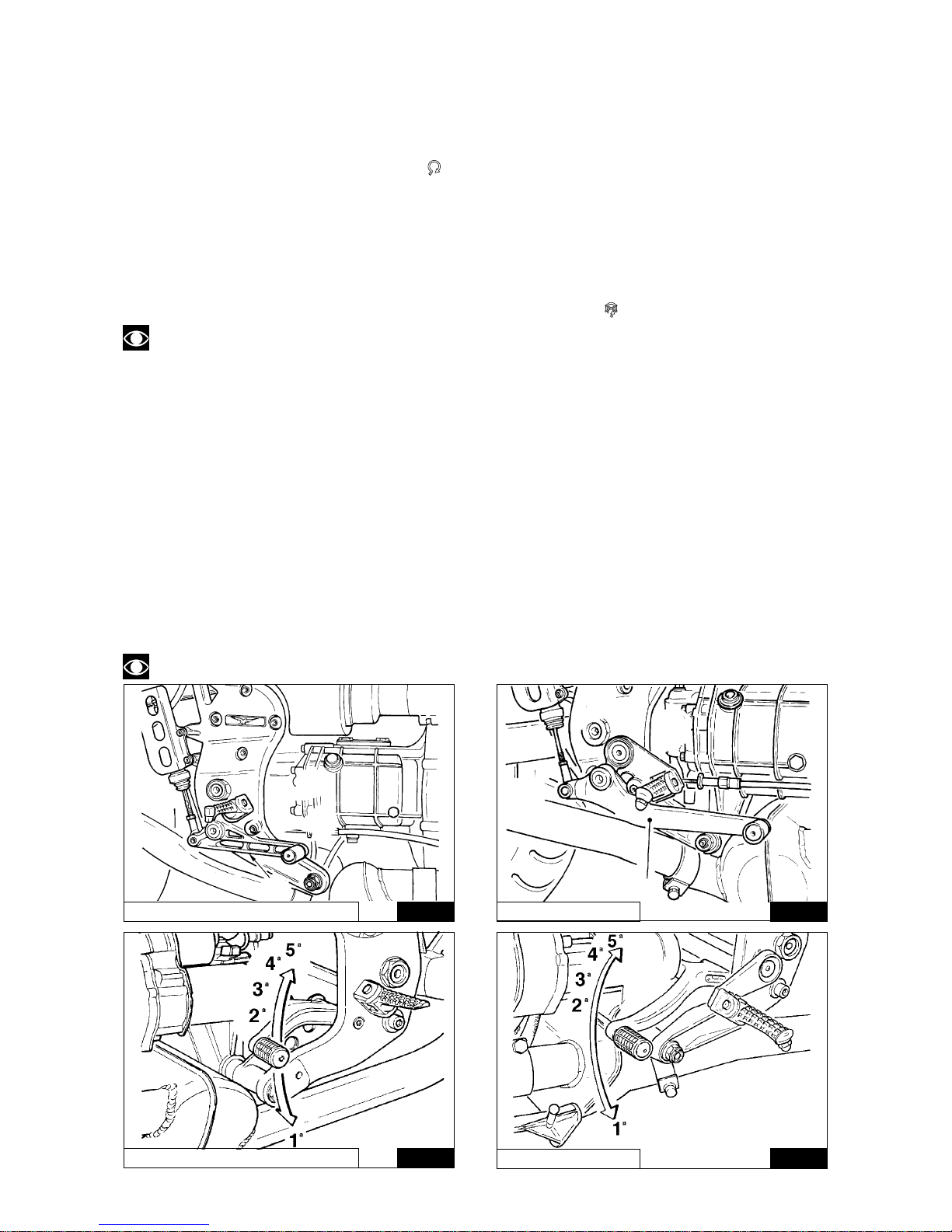
3.9 BRAKE PEDAL FOR REAR BRAKE («A» in Fig. 03-04)
This is centrally located on the right side of the vehicle and is linked to the rear brake master cylinder by a tierod.
3.10 GEARBOX CONTROL PEDAL (Fig. 03-05)
This is situated on the left of the motorcycle:
■ 1st gear: push pedal down;
■ 2nd, 3rd, 4th, 5th gears: pull pedal up;
■ neutral: between 1st and 2nd gears.
NOTE: Before changing gear disengage the clutch fully.
03-04
03-04
DAYTONA RS / SPORT 1100 I
V10 CENTAURO
03-05
DAYTONA RS / SPORT 1100 I
03-05
A
A
V10 CENTAURO
14
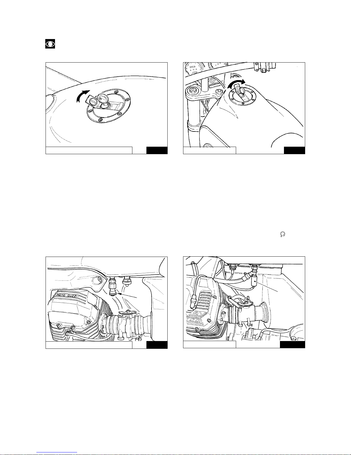
3.11 FUEL FILLER CAP (Fig. 03-06)
To open the filler cap, turn the key clockwise.
NOTE: Fuel spillage caused during refuelling should be cleaned immediately to prevent damage to
the fuel tank paintwork.
03-06
03-06
DAYTONA RS / SPORT 1100 I
V10 CENTAURO
3.12 FUEL TAP (DAYTONA RS / SPORT 1100 I) (Fig. 03-07)
The motor vehicle is fitted with a motor-driven pump that regulates the fuel flow from the tank to the engine.
If the petrol tank has to be removed, before disconnecting the pipes the tap «A» on the bottom of the tank on the
rear left-hand side must be tightly closed.
Approximately every 10000 km, clean the net filter on the tap.
3.13 ELECTRIC FUEL COCK (V10 CENTAURO) (Fig. 03-08)
The vehicle is provided with an electric cock «A» fitted on the left side under the tank, which operates
automatically, cutting off fuel flow to the throttle unit when the engine is not running.
It comes into play when the key of the change-over switch «1» on Fig. 03-01 is in its ON position «
».
Should the cock not be working properly, first check the condition of the fuse «3» on Fig. 03-09.
Approximately every 10000 km, clean the net filter on the tap.
03-07
03-08
V10 CENTAURO
A
A
DAYTONA RS / SPORT 1100 I
15
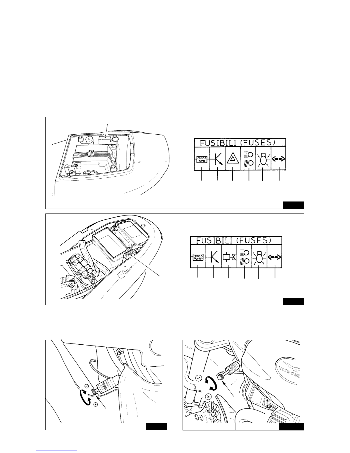
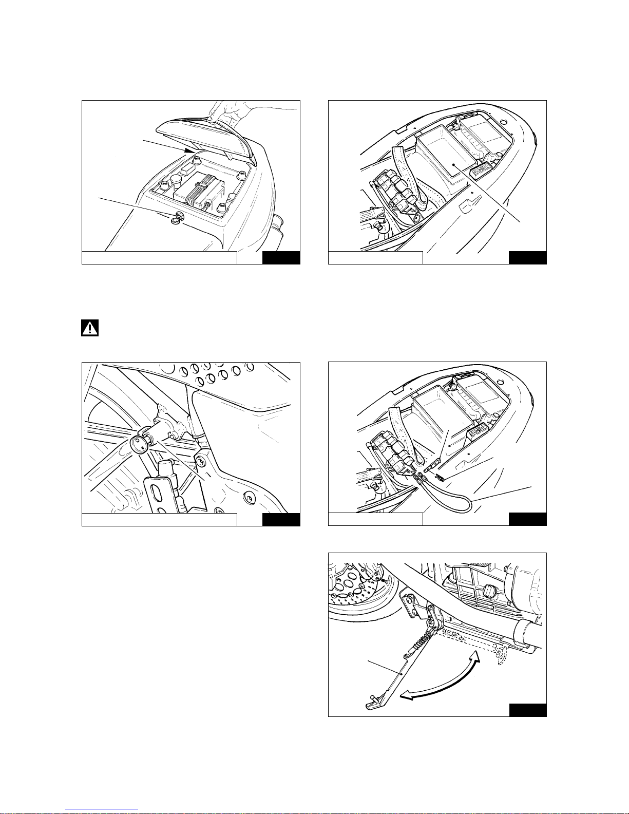
3.14 FUSE BOX («A» IN Fig. 03-09)
Situated on the rear right-hand side of the motorbike; remove the passenger seat to access to it (see Par. 3.20).
In the V10 CENTAURO the terminal board is located on the rear left side of the motorcycle; to reach it, remove
the saddle.
The fuse box has 6 «15 Amp» fuses; their functions are indicated by the decal on the cover.
Before changing a burnt fuse, trace and repair the cause of the trouble.
Fuse «1»: fuel pump, coils, electric injectors.
Fuse «2»: electronic box.
Fuse «3»: emergency flashers [electric cock in V10 CENTAURO model].
Fuse «4»: driving beam, traffic beam, passing light, horns, front lever stop light, rear pedal stop ligh, starting
motor.
Fuse «5»: tail light, dashboard lights, instruments lighting.
Fuse «6»: blinkers intermittence.
03-09
3.15 STEERING DAMPER (Fig. 03-10)
This is fitted on the front part of the motorbike between the frame and the steering base.
To increase or reduce the braking effect, screw or unscrew the knob «A».
DAYTONA RS / SPORT 1100 I
V10 CENTAURO
03-10
DAYTONA RS / SPORT 1100 I
03-09
03-10
V10 CENTAURO
A
1
2
3
45
6
A
1
2
3
45
6
A
A
16
3.16 DOCUMENTS AND OBJECTS HOLDER («A» Fig. 03-11)
It is located in the motorcycle rear side; to reach it, remove the passenger seat by releasing the lock «B» with
the same key of the ignition switch.
Model V10 CENTAURO: to reach it, you must remove the saddle (see «Removing the Saddle» on Par. 3.20).
03-11
03-11
DAYTONA RS / SPORT 1100 I
3.17 HELMET HOLDER (Fig. 03-12)
The helmet can be left with the motorcycle, using the helmet holder with lock «A».
DANGER: Never leave the helmet in the holder when the motorcycle is running, as it may interfere
with the moving parts.
03-12
03-12
DAYTONA RS / SPORT 1100 I
V10 CENTAURO
3.18 MOTORBIKE LATERAL SUPPORTING
ARM («A» - Fig. 03-13)
(VALID FOR ALL MODELS
MANUFACTURED UNTIL 12/12/1997)
The motorbike is equipped with an arm that serves as
a lateral support during parking; when the motorbike
is moved to an upright position the lateral arm
automatically returns to the rest position.
A
B
A
A
A
C
B
03-13
A
V10 CENTAURO
17
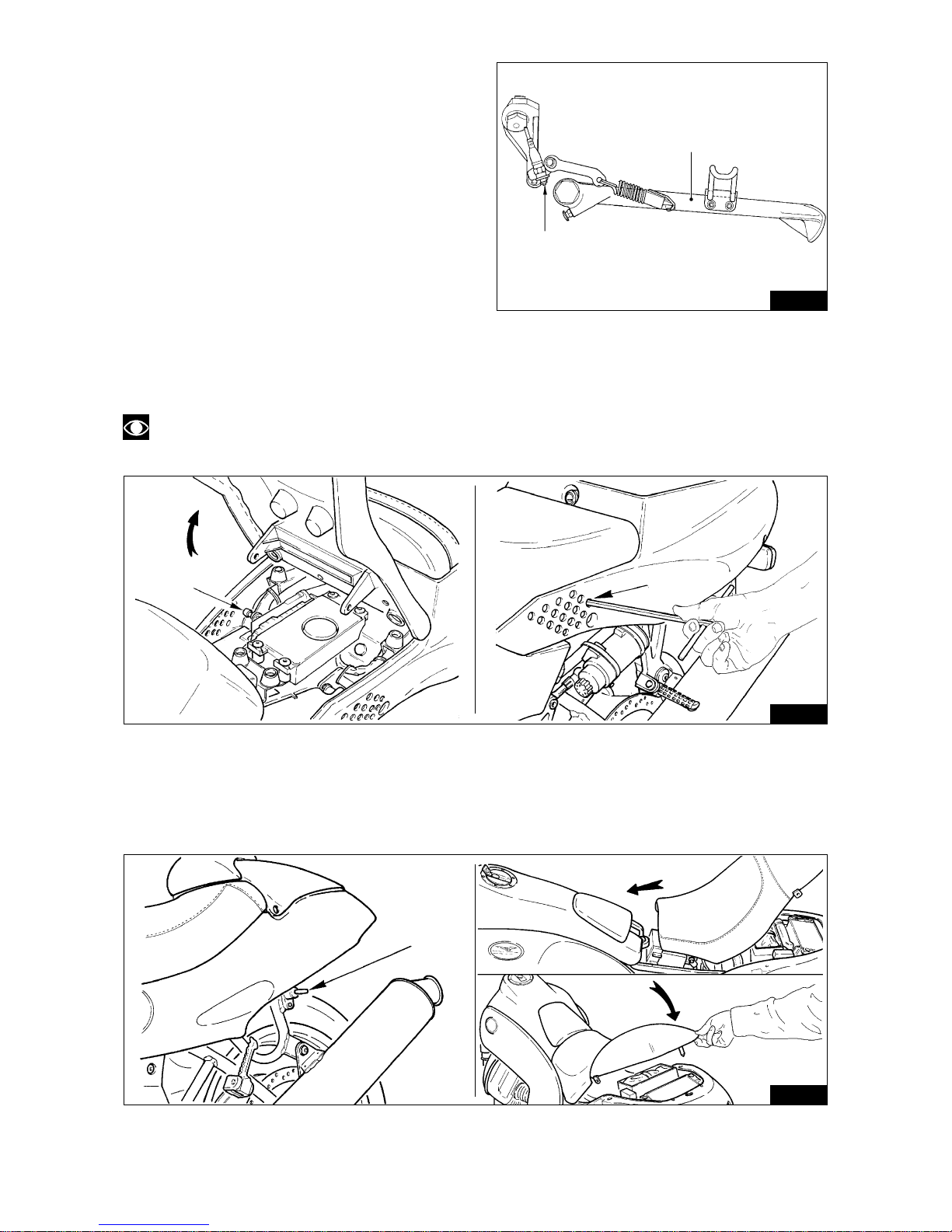
3.18.1 SIDE STAND FOR MOTORCYCLE
SUPPORT WITH SAFETY SWITCH
(VALID FOR ALL MODELS
MANUFACTURED AFTER JAN. 1 1998)
The motorcycle is equipped with a side stand that
supports it during parking («A» - Fig. 03-14).
When the stand is in parking position (all out) the
microswitch («B» - Fig. 03-14) operates a remote
control switch that breaks the current delivery to
the starting motor: in these conditions the motor
cannot be started.
03-14
3.20 REMOVING THE SADDLE (V10 CENTAURO - Fig. 03-16)
To remove the saddle from the frame, you must: release the saddle using the key «A».
To fasten the saddle, you must fit it into its seat on the fuel tank and then press down on its rear part.
03-15
03-16
3.19 DRIVER SEAT REMOVAL (DAYTONA RS AND SPORT 1100 I - Fig. 03-15)
To remove the seat from the chassis use a 6 mm Allen wrench to unscrew, from both sides, the screw-pins «A»
which can be reached through the holes «B» made on the tail side.
NOTE: It is not necessary to completely unscrew the screws, just loosen them as required to remove
the seat.
A
B
B
A
A
18
03-17
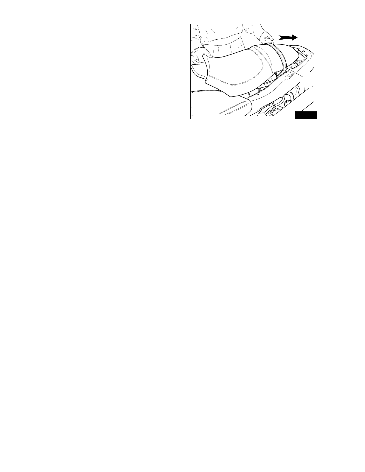
3.21 PASSENGER HOLDING BELT
(V10 CENTAURO)
(Fig. 03-17)
The motorcycle is equipped with a passenger holding
belt originally located underneath the saddle.
To use it proceed as follows:
■ Release the saddle from the frame (Fig. 03-16);
■ Dismantle the saddle-covering fairing (if
assembled);
■ Lift the belt and insert the saddle between it and
the frame;
■ Fasten the saddle back in place.
A
19
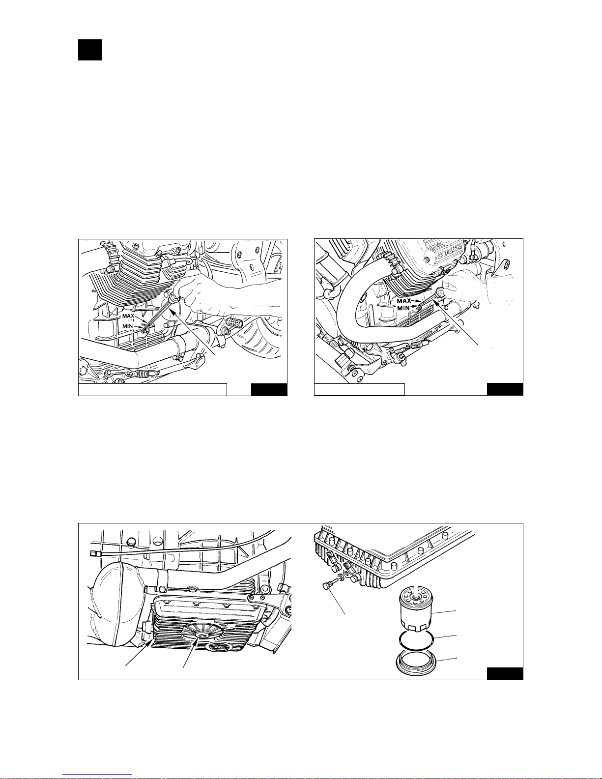
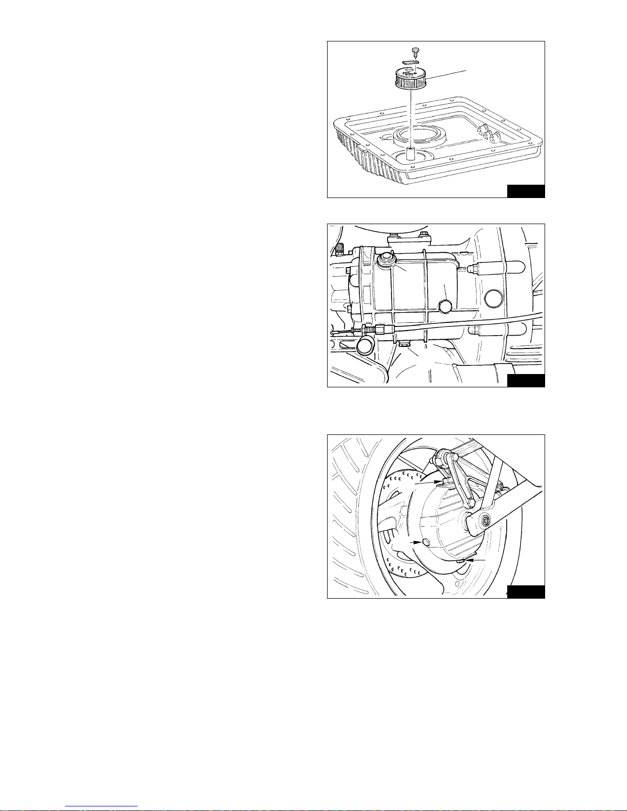
4.2 CHANGING THE FILTER CARTRIDGE AND CLEANING THE MESH FILTER (Fig. 04-02)
After the first 500÷1500 km (first oil change) and then every 10,000 km (2 oil changes), replace the filter cartridge
as follows:
■ unscrew the oil drain plug «B» and drain all oil out of the sump;
■ unscrew the cover «A» using the tool code 01929100;
■ unscrew the filter cartridge «C» using the same tool and replace it with an original cartridge.
When refitting cover «A», check its oil seal «D» and replace it if necessary.
These operations are best carried out by an authorized dealer.
04-02
04-01
04-01
DAYTONA RS / SPORT 1100 I
A
V10 CENTAURO
A
A
B
B
C
D
A
4 LUBRICATION
4.1 ENGINE LUBRICATION (Fig. 04-01)
Checking the oil level
Check the crankcase oil level every 500 km; the oil should reach the «Max» mark of the dipstick «A».
If the oil is below this level, top up with the recommended type and grade of oil.
The oil level check should be carried out after the engine has run for a few minutes: the dipstick plug «A»
should be screwed fully home.
Oil change
The oil should be changed after the first 500÷1500 km and every 5000 km thereafter. Change the oil when the
engine is warm.
Allow the sump to drain fully before filling with new oil .
«A» Oil filler plug with dipstick Fig. 04-01.
«B» Oil drain plug Fig. 04-02.
Oil required: about 3,5 litres of «Agip 4T Super Racing SAE 20W/50».
20
Washing the wire mesh filter (Fig. 04-03)
After the first 500÷1500 km, (first oil and filter cartridge
change), and then every 30.000 km it is recommended
to remove the oil sump from the engine block, remove
the wire mesh filter «E» and wash everything in
petrol; then blow the filter with a compressed air jet.
Don’t forget to fit a new sump gasket when refitting
the sump.
These operations are best carried out by an authorized
dealer.
4.3 GEARBOX LUBRICATION (Fig. 04-04)
Checking the oil level
Check the oil level every 5000 km; the oil should just
reach the level plug hole «B».
If the oil is below this level top up with the
recommended grade and type of oil.
Oil change
The gearbox oil should be changed every 10.000 km.
Drain the oil when the gearbox is warm as the oil is
more fluid and drains more easily. Allow the gearbox
to drain fully before filling with new oil.
«A» Filler plug.
«B» Level plug.
«C» Drain plug.
Oil required: 0.750 litres of «Agip Rotra MP SAE
80W/90».
04-03
04-05
04-04
E
B
C
A
B
A
C
4.4 REAR TRANSMISSION BOX LUBRICATION
(Fig. 04-05)
Checking the oil level
Check the oil level every 5000 km; the oil should just
reach the level plug hole «A».
If the oil is below this level top up with the recommended
grade and type of oil.
Oil change
The transmission box oil should be changed every
10.000 km. Drain the oil when the box is warm as the
oil is more fluid and drains more easily.
Allow the box to drain fully before filling with new oil.
«A» Level plug.
«B» Filler plug.
«C» Drain plug.
Oil required: 0.250 litres of which:
0.230 lt. is «Agip Rotra MP SAE 80W/90»;
0.020 lt. is «Agip Rocol ASO/R» or «Molykote type A».
21
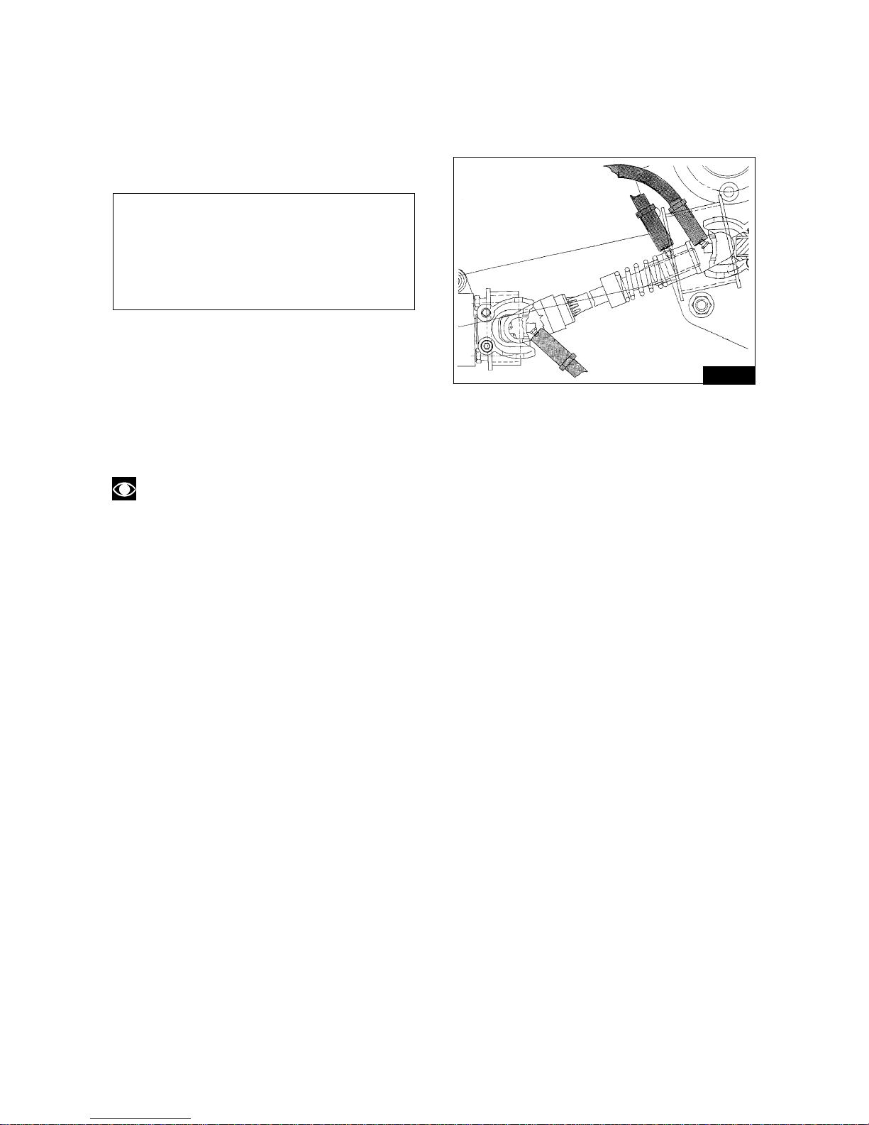
4.5 GREASING THE DRIVING SHAFT (Fig. 04-06)
The vehicle has a driving shaft provided with greasers. The greasing operation of the 3 places shown in figure
should be made every 2500 kms (every 1000 Km in case of continuous usage at high speed) or at least once
a year if the number of kilometers is lower.
Lubrication is recommended every time the motorbike is washed.
TYPES OF GREASE TO BE USED
■ AGIP GREASE 30
■ AGIP GR LP2
■ ESSO LADEX 2
■ MOBIL PLEX 48
■ SHELL RHODINA GRIS 2
■ SHELL SUPERGRIS EP 2
04-06
4.6 FRONT FORK OIL CHANGE
Change fork oil about every 15,000 km or at least once a year.
Amount of oil required: about 0,400 litres cartridge oil «WP suspension - REZ 71 (SAE 5)».
NOTE: For further details on the oil replacement procedure, refer to the fork section in Chapter 17.
4.7 GREASING
To grease:
■ steering bearings;
■ swinging arm bearings;
■ control rod joints;
■ side stand fittings;
■ Articulated joints and needle bearing - rear driving box.
Use: «Agip Grease 30».
22
5 MAINTENANCE AND ADJUSTMENTS
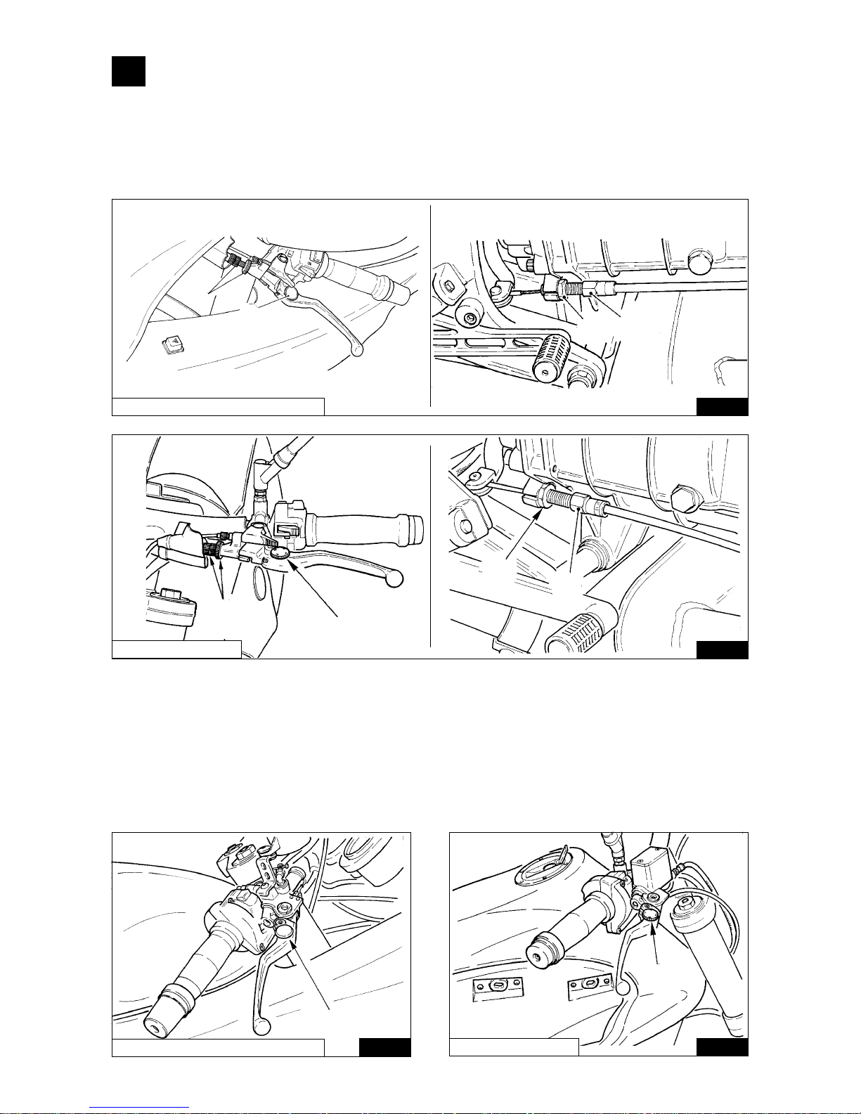
5.1 ADJUSTING THE CLUTCH LEVER (Fig. 05-01)
There should be 3÷4 mm of free play at the lever; turn the adjuster screw «A» to obtain the desired play
Play can also be adjusted on the cable adjuster «B» located on the right side of the gearbox. First loosen the lock
nut «C» and then adjust.
The distance of the handle lever can be adjusted by turning ring nut «D» which has 4 positions.
05-01
05-01
V10 CENTAURO
05-02
DAYTONA RS / SPORT 1100 I
A
D
C
B
A
D
C
B
DAYTONA RS / SPORT 1100 I
5.2 ADJUSTING THE FRONT BRAKE LEVER (Fig. 05-02)
The distance of the handle lever can be adjusted by turning ring nut «A» which has 4 positions.
A
05-02
V10 CENTAURO
A
23
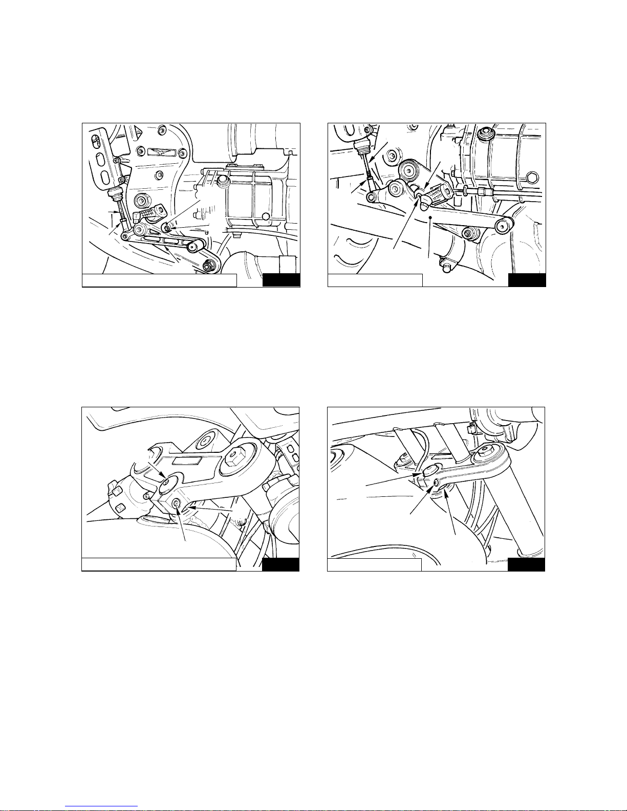
5.3 REAR BRAKE PEDAL ADJUSTMENT (Fig. 05-03)
Check that brake pedal «A» has an idle stroke of approx. 5÷10 mm. before the end of rod «B» comes into contact
with the brake pump master cylinder; otherwise alter the length of rod «B» by tightening or untightening it, after
having loosened off lock nut «C».
To change the position of the pedal «A», loosen the screw «D» and adjust the cam «E»; at the same time vary
the length of the rod «B» until the correct clearance is obtained.
05-03 05-03
DAYTONA RS / SPORT 1100 I
V10 CENTAURO
5.4 ADJUSTING THE STEERING (Fig. 05-04)
To ensure safe riding, the steering should be adjusted in such a way as to allow free movement of the handlebars
without any play.
• loosen the steering head fixing bolt «A»;
• undo the steering head nut «B»;
• turn the adjuster nut «C» to take up any play.
When the play has been adjusted, tighten nut «B» and the steering head fixing bolt «A».
DAYTONA RS / SPORT 1100 I
05-04
05-04
D
E
C
A
B
B
C
D
A
E
V10 CENTAURO
A
C
B
C
A
B
24
5.5 ADJUSTMENT OF TELESCOPIC FORK (Fig. 05-05)
The motorbike is fitted with an hydraulic telescopic fork with separate adjustment of the rebound damping and
compression damping.
Hydraulic damping can be adjusted turning adjuster screws «A» and «B» with a screw driver.
The left-hand adjuster screw «A» adjusts hydraulic rebound damping, the righ-hand screw «B» if for compression
damping.
Both adjuster screws have several settings (clicks); turning clockwise (+) you will get a stiffer damping, turning
anticlockwise (–) will give a softer damping.
NOTE: Do not try to turn the adjusters screws further than their limit positions.
DAYTONA RS / SPORT 1100 I
05-05
05-05
V10 CENTAURO
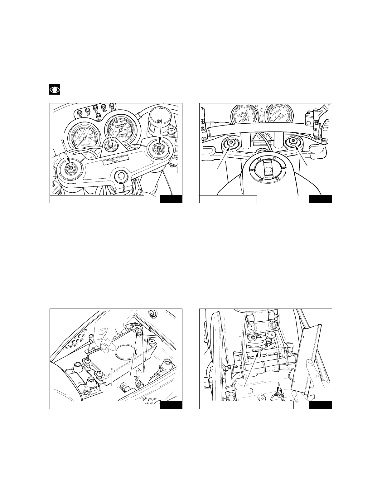
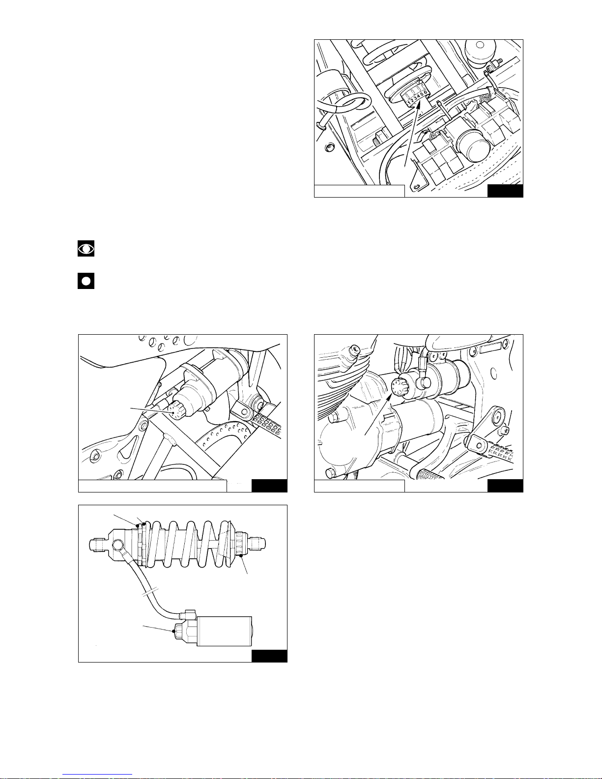
5.6 REAR SUSPENSION ADJUSTMENT (Fig. 05-06 / 05-07 / 05-08 / 05-09)
NOTE: The changes concerning the V10 CENTAURO model are shown in brackets [ ].
The motorcycle is equipped with “WHITE POWER” single shock absorbers with separate adjustment of the
springs pre-loading and the rebound damping and compression damping.
The shock absorber is calibrated in the factory to the following standard values:
REBOUND: position 5 [1] (ring nut A)
COMPRESSION: position 4 [1] (knob B)
SPRING PRELOADING:14 mm [11 mm]
Use the adjusting ring nut «A» shown in Fig. 05-07 to adjust the rebound damping. Access to the ring nut is
obtained by removing the rider seat (see Par. 3.19 «REMOVAL OF RIDER SEAT») and the computer box «1»
shown in Fig. 05-06.
05-06
05-07
DAYTONA RS / SPORT 1100 I
DAYTONA RS / SPORT 1100 I
A
B
A
B
3
1
2
A
2
25
In the V10 CENTAURO model, the adjustment ring
nut«A» - Fig. 05-07 can be reached by removing the
saddle (see Removing the saddle in Chapter 3.20)
and moving the battery.
According to needs and the load on the motorcycle,
the damper can be set from position “1” (very soft) to
position “11” (very hard).
The hydraulic damper in compression can be set by
turning adjusting knob «B» in Fig. 05-08 that has nr.
7 setting positions; from position “1” minimum
damping, to position “7” maximum damping.
To adjust the pre-loading of the spring, using the
correct wrench, loosen off ringnut «C» and adjust
ringnut «D»; tightening up increases the spring preloading (see Fig. 05-09).
The spring preload, starting from a completely
05-07
DAYTONA RS / SPORT 1100 I
05-08
05-08
V10 CENTAURO
05-09
released spring, is 10 to 18 mm.
The released spring length is 165 mm.
NOTE: To avoid damaging the thread between the damper body and the ring nut «D», lubricated the
thread with «SVITOL», with oil or with grease.
WARNING
In the model DAYTONA RS and SPORT 1100 I When refitting the electronic box, do not forget to reconnect the terminals of the ground wires «2» under the fastening screw «3» of the electronic box (see
Fig. 05-06 and 05-07).
A
B
B
A
D
C
B
V10 CENTAURO
26
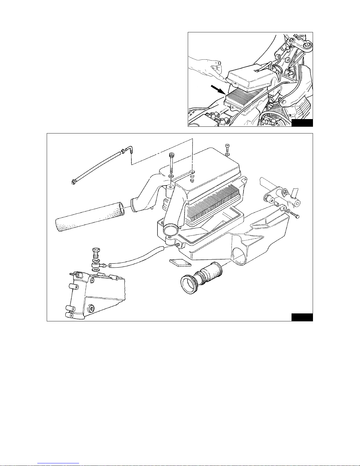
5.7 CHANGING THE AIR FILTER (DAYTONA RS AND SPORT 1100 I - Fig. 05-10)
Check the air filter every 5000 km and clean by
blowing with compressed air; change every 10.000 km.
This filter is installed inside a proper housing over the
motor unit. To reach it, remove the driver saddle, the
body sides and the fuel tank (see SPECIFIC
INSTRUCTIONS par. 9.2).
05-10
05-11
27
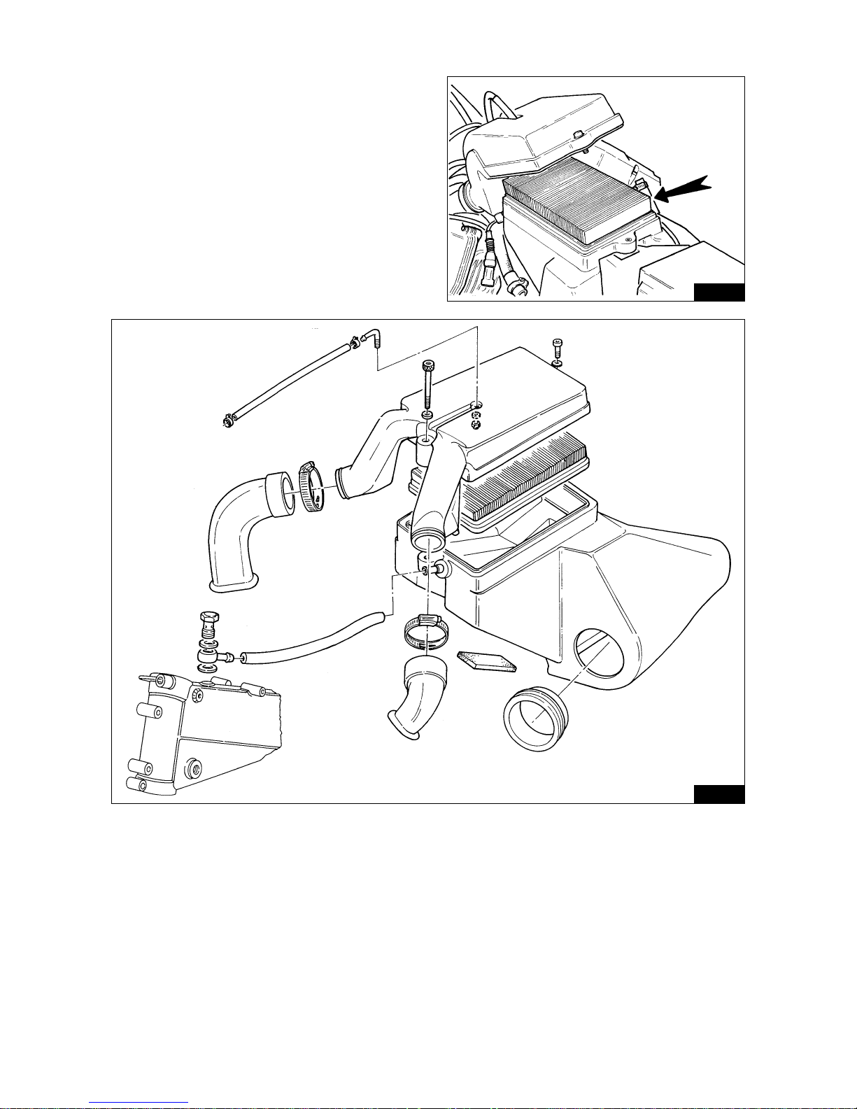
5.7.1 CHANGING THE AIR FILTER (V10 CENTAURO) (Fig. 05-12)
Check the air filter every 5000 km and clean by
blowing with compressed air; change every 10.000 km.
This filter is assembled in a special housing above the
engine unit; to reach it, you must take off the saddle,
the sides and the fuel tank (see SPECIFIC
INSTRUCTIONS par. 9.1).
05-12
05-13

28
5.8 TAPPET CLEARANCE CHECKING (Fig. 05-14)
After the first 500÷1500 km, and then every 5000 km or when the valves are very noisy, check the clearance
between the valves and the rockers.
This check is done on a cold engine, with the piston at top dead center «T.D.C.» at the end of the compression
stroke (valves fully closed).
Remove the rocker cover and proceed as follows:
1 Loosen nut «A».
2 adjust screw «B» to set the following clearances, using a feeler gauge:
■ intake valve 0.10 mm;
■ exhaust valve 0.15 mm.
Use a suitable feeler gauge «C» to measure the clearance.
Note that excessive clearance causes noise, whereas with insufficient clearance the valves do not close fully,
causing:
■ compression loss;
■ engine overheating;
■ valve burning, etc.
5.8.1 TIMING BELTS (DAYTONA RS AND V10 CENTAURO)
Every 30,000 km replace the distribution timing belts.
SPORT 1100 I
05-14
05-14
5.9 ADJUSTING THE HEADLIGHT BEAM (Fig. 05-15)
The headlight beam should always be kept adjusted to the correct height to ensure good visibility and to avoid
dazzling oncoming traffic. For vertical adjustment, turn screw «A», and move the light up or down as required.
In the V10 CENTAURO model, the vertical orientation can be obtained by loosening the two screws «C» which
fasten the headlight and manually moving it upward or downward until the required height is reached.
DAYTONA RS / SPORT 1100 I
05-15
05-15
V10 CENTAURO
C
A
B
V10 CENTAURO / DAYTONA RS
A
C
B
A
C
C
B
 Loading...