

Page 1
Manufactured by Mortara Instrument, Inc., Milwaukee, Wisconsin U.S.A.
REF 9516-190-50-ENG Rev F1
Surveyor
S4 Mobile Monitor
SERVICE MANUAL
CAUTION: United States federal law restricts this device to sale by or on the order of a
physician.
Page 2

Page 3

Mortara, the Mortara logo, Surveyor, and VERITAS are tra demarks belonging to Mortara Instrument, Inc.
Clorox Healthcare® is a registered trademark of The Clorox Company.
Copyright © 2016
by Mortara Instrument, Inc.
7865 N. 86th Street
Milwaukee, Wisconsin 53224
This document contains confidential information that belongs to Mortara Instrument, Inc. No part of this document
may be transmitted, reproduced, used, or disclosed outside of the receiving organization without the express written
consent of Mortara Instrument, Inc. Mortara is a registered trademark of Mortara Instrument, Inc. E-Scribe, ELI,
®
and VERITAS are trademarks of Mortara Instrument, Inc. Cisco
DICOM
®
is the registered trademark of the National Electrical Manufacturers Association for its standards
is the registered t rademark of Cisco Systems, Inc.
publications relating to digital communications of medical information.
Page 4

Page 5

TECHNICAL SUPPORT AND SERVICE
Headquarters
Sales Support/
Fax: +44.1786.446630
Mortara Instrument, Inc.
7865 North 86th Street
Milwaukee, WI 53224
U.S.A.
Tel: 414.354.1600
Tel: 800.231.7437
Fax: 414.354.4760
Internet: http://www.mortara.com
European Union
Representative
Mortara Instrument Europe, s.r.l.
(European Headquarters)
Via Cimarosa 103/105
40033 Casalecchio di Reno (BO)
Italy
Tel: +39.051.298.7811
Fax: +39.051.613.3582
Service/Technical
Support Group
Mortara Instrument, Inc.
7865 North 86th Street
Milwaukee, WI 53224
U.S.A.
Tel: 414.354.1600
Service: 888.MORTARA
(888.667.8272)
Fax: 414.354.4760
E-mail: [email protected]
24-hour Technical Support
Same-day Shipment of Replacement Parts
Biomedical Training Classes
Extended Warranties/Service Contracts
Supplies & Accessories
Mortara Instrument, Inc.
7865 North 86th Street
Milwaukee, WI 53224
U.S.A.
Tel: 414.354.1600
Fax: 414.354.4760
E-mail: [email protected]
Hospital Customers: [email protected]
Physician Practice: [email protected]
U.S. Distribution: [email protected]
Mortara Instrument Germany
Bonifaciusring 15
45309 Essen
Germany
Tel: +49.201.18 55 69 70
Fax: +49.201.18 55 69 77
Mortara Instrument Netherlands
Postbus 324
5680 AH Best
Industrieweg 160b
5683 CG Best
Netherlands
Tel: +31.499.377310
Fax: +31.499.377908
Mortara Instrument Australia
PO Box 7568
Baulkham Hills NSW 2153
Unit 28, 9 Hoyle Avenue
Castle Hill NSW 2154
Australia
Tel: +61 2 8070 9303
Fax: +61 2 9899 9478
Mortara Dolby UK Ltd.
Units 11 & 12, Scion House
Stirling University Innovation Park
Stirling FK9 4NF
Scotland
Tel: +44.1786.444980
i
Page 6

TECHNICAL SUPPORT AND SERVICE
ii
Page 7

TABLE OF CONTENTS
GENERAL INFORMATION SECTION 1
Notices ........................................................................................................................................................................... 1
Warranty Information .................................................................................................................................................... 3
User Safety Information ............................................................................................................................................... 4
Equipment Symbols and Markings .............................................................................................................................. 11
Electromagnetic Compatibility (EMC) ........................................................................................................................ 12
MAINTENANCE & CLEANING SECTION 2
Preventive M aintenance Schedule ............................................................................................................................... 18
Visual Inspection ......................................................................................................................................................... 18
Cleaning and Disinfecting ........................................................................................................................................... 19
Maintenance ................................................................................................................................................................ 21
UNIT DISASSEMBLY SECTION 3
Cautions and Special Inst ructions ................................................................................................................................ 23
Battery Removal .......................................................................................................................................................... 24
SAM/Housing Removal .............................................................................................................................................. 26
PCBA Replacement ..................................................................................................................................................... 30
S4 Mobile Monitor Item Desc ription Listing ................................................................................................ 31
S4 Mobile Monitor Item Identification Table ............................................................................................... 33
CONFORMANCE TESTING SECTION 4
Required Equipment .................................................................................................................................................... 35
Unit Vacuum Leak Test (IP X4 Ratin g) ....................................................................................................................... 36
Functional Testing ....................................................................................................................................................... 36
Safety Testing .............................................................................................................................................................. 41
Device Cleaning .......................................................................................................................................................... 43
S4 Mobile Monitor Conformance Test Data Record ................................................................................................... 44
DEVICE SPECIFICATIONS SECTION 5
General ........................................................................................................................................................................ 46
Environmental ............................................................................................................................................................. 46
Power Requirements and Battery ................................................................................................................................ 47
ECG Specifications...................................................................................................................................................... 47
Specifications .................................................................................................................................................... 48
SpO
2
Wireless Network Specifications ................................................................................................................................. 48
TROUBLESHOOTING SECTION 6
Troubleshooting ........................................................................................................................................................... 51
Error Messages ............................................................................................................................................................ 55
WiFi Diagnostics ......................................................................................................................................................... 56
iii
Page 8

TABLE OF CONTENTS
iv
Page 9

NOTICES
Manufacturer’s Responsibility
Mortara Instrument, Inc. (Mortara) is responsible for the effects on safety and performance of the Surveyor™ S4
mobile monitor, as indicated by the
•
• The mobile monitor is used in accordance with the instructions for use.
• The mobile monitor is correctly maintained according to the standards authorized by Mortara using original
• The mobile monitor is used with original accessories and supplies that are in compliance with the standard
• The electrical installation of the relevant room complies with the requirements of appropriate regulations.
WARNING: Only Mortara authorized service providers should perform servicing of the S4 to ensure
that the correct maintenance and calibration procedures are followed and that the S4 is returns to proper
operation.
spare parts.
specifications described in thi s manual.
label, only if article 2 of 93/42/EEC directive is applied, in particular:
Responsibility of the Custom er
The user of this mobile monitor is responsible for ensuring the implementation of a satisfactory maintenance
schedule. Failure to do so may cause undue failure and possible health hazards. This manual must be kept in a safe
place to prevent its deterioration and/or alteration. The user and Mortara authorized personnel must have access to
this manual at any time. The user of this mobile monitor must periodically check the accessories, their functionality
and integrity.
Equipment Identificati on
Mortara equipment is identified by a serial and reference number on the back of the mobile monitor. Care should be
taken so that these numbers are not defaced.
Copyright and Trademark Notices
This document contains information that is protected by copyright. All rights are reserved. No part of this
document may be photocopied, reproduced, or translated into another language without prior written consent of
Mortara.
Other Important Informat ion
The infor mation in this document is subject to change without notice.
Mortara makes no warranty of any kind with regard to this material including, but not limited to, implied warranties
of mer chantability and fitness for a particular purpose. Mortara assumes no responsibility for any errors or
omissions that may appear in this document. Mortara makes no commitment to update or to keep current the
information contained in this document.
1
Page 10

Page 11

WARRANTY INFORMATION
Your Mortara Warranty
MORTARA INSTRUMENT, INC. (hereafter referred to as “Mortara”) warrants that components within Mortara
products (hereafter referred to as “Product/s”) will be free from defects in workmanship and materials for the
number of years specified on documentation accompanying the product, or previously agreed to by the purchaser
and Mortara, or if not otherwise noted, for a period of twelve (12) months from the date of shipment.
Consumable, disposable or single use products such are warranted to be free from defects in workmanship and
materials for a period of 90 days from the date of shipment or the date of first use, whichever is soo ner .
Reusable product such as, but not limited to, BATTERIES, PATIENT CABLES, LEAD WIRES, MAGNETIC
STORAGE MEDIUMS, CARRY CASES or MOUNTS, are warranted to be free from defects in workmanship and
materials for a period of 90 days. This warranty does not apply to damage to the Product/s caused by any or all of
the following circumstances or c onditions:
a) Freight damage;
b) Supplies, accessories and internal parts NOT approved by Mortara;
c) Misapplication, misuse, abuse, and/or failure to follow the Pro duct/s instruction sheets and/or information
guides;
d) Accident;
e) A disaster affecting the Product/s;
f) Alterations and/or modifications to the Product/s not authorize d by Mortara;
g) Other events outside of Mortara’s reasonable control or not arising under normal operating conditions.
THE REMEDY UNDER THIS WARRANTY IS LIMITED TO THE REPAIR OR REPLACEMENT WITHOUT
CHARGE FOR LABOR OR MATERIALS, OR ANY PRODUCT/S FOUND UPON EXAMINATION BY
MORTARA TO HAVE BEEN DEFECTIVE. This remedy shall be conditioned upon receipt of notice by Mortara
of any alleged defects promptly after discovery thereof within the warranty period . Mortara’s obligatio ns under the
foregoing warranty will further be conditioned upon the assumption by the purchaser of the Product/s (i) of all
carrier charges with respect to any Product/s returned to Mortara’s principal place or any other place as specifically
designated by Mortara or an authorized d istributor or r epresentative of Mortar a, and (ii) all risk of loss in tra nsit. It
is expressly agreed that the liability of Mortara is limited and that Mortara does not function as an insurer. A
purchaser of a Product/s, by its acceptance and purchase thereof, acknowledges and agrees that Mortara is not liable
for loss, harm, or damage due directly or indirectly to an occurrence or consequence there from relating to the
Product/s. If Mortara should be found liable to anyone under any t heory (except the expressed warranty set forth
herein) for loss, harm, or damage, the liability of Mortara shall be limited to the lesser of the actual loss, harm, or
damage, or the original purchase price of the Product/s when sold.
EXCEPT AS SET FORTH HEREIN WITH RESPECT TO REIMBURSEMENT OF LABOR CHARGES, A
PURCHASER’S SOLE EXCLUSIVE REMEDY AGAINST MORTARA FOR CLAIMS RELATING TO THE
PRODUCT/S FOR ANY AND ALL LOSSES AND DAMAGES RESULTING FROM ANY CAUSE SH ALL BE
THE REPAIR OR REPLACEMENT OF DEFECTIVE PRODUCT/S TO THE EXTENT THAT THE DEFECT IS
NOTICED AND MORTARA IS NOTIFIED WITHIN THE WARRANTY PERIOD. IN NO EVENT,
INCLUDING THE CLAIM FOR NEGLIGENCE, SHALL MORTARA BE LIABLE FOR INCIDENTAL,
SPECIAL, OR CONSEQUENTIAL DAMAGES, OR FOR ANY OTHER LOSS, DAMAGE, OR EXPENSE OF
ANY KIND, INCLUDING LOSS OF PROFITS, WHETHER UNDER TORT, NEGLIGENCE OR STRICT
LIABILITY THEORIES OF LAW, OR OTHERWISE. THIS WARRANTY I S EXPRESSLY IN LIEU OF ANY
OTHER WARRANTIES, EXPRESS OR IMPLIED, INCLUDING, BUT NOT LIMITED TO THE IMPLIED
WARRANTY OF MERCHANTABILITY AND THE WARRANTY OF FITNESS FOR A PARTICULAR
PURPOSE.
3
Page 12

USER SAFETY INFORMATION
Warning:
Means there is the possib ility of personal injur y to you or others.
Caution:
Means there is the possibility of damage to the mobile monitor.
Note:
Provides information to further assi s t in the use of the mobile monitor.
NOTE: This manual may contain screen shots and pictures. Any screen shots and pictures are provided
for reference only and are not intended to convey actual operating techniques. Consult the actual screen in
the host language for specific wording.
Safety Regulations
• The Surveyor S4 (henceforth referred to as either Surveyor S4 or S4) is a medical mobile monitor.
• The S4 and its accessories are
• The S4 with all accessories that have a physical or logical connection with it, forms part of a Medical Electrical
System.
• The S4 complies with various safety and performance regulations as mentioned in this manual (Applied
Standards).
labeled, according to applicable standards.
Warnings
• This manual gives important information about the use and safety of this mob ile monitor. Deviating fr om
operating procedures, misuse or misapplication of the mobile monitor, or ignoring specifications a nd
recommendations could result in increased risk of harm to users, patients and bystanders, or damage to the
mobile monitor.
• Users are expected to be licensed clinical professionals knowledgeable about medical procedures and patient
care, and adequately trained in the use of this mobile monitor. The S4 mobile monitor captures and presents
data reflecting a patient’s physiological condition that when reviewed by a trained physician or clinician can be
useful in determining a diagnosis; however, the data should not be used as a sole means for determining a
patient’s diagnosis.
• Before attempting to use this de vice for c linical applications, the operator must read and understand the
contents of the user manual and other accompanying documents. Inadequate knowledge or training could result
in increased risk of harm to users, p atients and bys t anders, or damage to the mobile monitor. Contact Mortara
for additional training options.
• Operation of the equipment beyond its specified ranges, or beyond normal physiological conditions of human
subjects, may cause inaccurate results.
• A possible explosion hazard exists. Do not use the device in the presence of a flammable anesthetic mixture.
Do not mount any part of the device closer than 25 cm from outlets of flammable gases, including oxygen.
• For proper operation and the safety of users or patients and bystanders, equipment and accessories must be
connected only as described in the user manual.
• Repairs and modification must be made by authorized and trained technical personnel. Unauthorized
modifications and repairs will void the S4 warranty and may pose a danger to patients and users.
4
Page 13

USER SAFETY INFORMATION
• If additional devices beyond the S4 are connected to the patient, leakage currents could add up and should be
accounted for.
• The S4, as all medical equipment or systems, requires special precautions regarding EMC, and should be
installed and put into service according to the EMC information provided in the installation procedure to obtain
a sufficient degree of immunity as well as not to create disturbance to other equipment. Refer to the specific
EMC instructions in the user manual.
• The quality of the signal produced by the device may be adversely affected by the use of other medical
equipment, including but not limited to electrosurgery and ultrasound ma chines. Do not use the S4 system in
the presence of imaging equipment such as magnetic resonance imaging (MRI) and tomography systems.
Simultaneous operation may damage the device or lead to erroneous results.
• There is no known safety hazard if other equipment, such as pacemakers or other stimulators, is used
simultaneo usly with the device; however, dist urbance to the signal may occur.
• Portable and mobile RF communications equipment may affect medical elec trical equipment or systems as well
as the S4 and its accessories. Do not operate the S4 near sources of high frequency emissions (e.g.
microwaves). Unauthorized wireless devices, such as personal access points and WiFi hotspots including those
available on personal smartphones, may also interfere with the operation of the system.
• A mobile monitor is not intended to replace clinical assessments. It is important that a qualified individual
regularly supervise the patient.
• The S4 is restricted to use on one patient at a time.
Power Supply Warnings
• Only use the recommended batteries. Use of alternate batteries may damage the device or cause other hazards.
• Only charge Mortara Rechargeable Battery (Mortara Re-Order Number 4800-018) in the Mortara Li-Ion
Battery Charger. Attempting to charge unauthorized batteries may result in damage to the unauthorized battery
and/or the Li-Ion Battery Charger.
• The S4 is a battery operated device that transmits data reflecting a patient’s physiological condition to a
receiving device. During operation failure, data transmission and LCD information will cease to occur. In the
case of battery depletion, replace the batteries on the device to resume monitoring. In mission critical
conditions, it is advisable to have a backup device available.
• Only use the Mortara-provided external battery charger and adapter with the S4. Ensure that the electrical
installation also complies with local safety requirements for the enviro nment where it is used.
• Regularly check all cables for damage and proper connection. Do not use equipme
• The S4 contains an inter nal battery. The following preca utions should be taken regar ding the internal batte ry:
nt with a damaged cable.
o Do not immerse in water.
o Do not heat or throw in fire.
o Do not leave in conditions over 60 ºC.
o Do not crush or drop.
o Only use the approved batteries.
o Follow the instructions in the disposal section of this manual when taken out of service.
5
Page 14

USER SAFETY INFORMATION
• The S4 rechargeable battery must be initially fully charged prior to use.
• When the S4 initially powers on, the screen will illuminate if the batteries are installed properly and charged.
Remove the S4 from service and contact Mortara if the screen does not activate when new or fully charged
batteries are initially installed.
• AA batteries are known to leak their contents when stored for an extended period of time in unused equipment.
Always remove the batteries after completing operating the mobile monitor. Always place rechargeable
batteries in the battery charge r when not in use. This ensures that the batteries are recharged for the next time
the mobile monitor is operated.
• There is a potential pinch hazard when applying the battery compartment cover to the device that could result in
minor injury. Care should be taken to avoid entrapment of fingers when performing this operation.
Accessories, Cables, and External Connections Warnings
• The S4 is designed to meet applicable specifications when using Mortara-approved patient cables and
accessories. Use of non-approved cables and accessories may result in reduced performance or electromagnetic
interference, and may pose possible patient and user safety concerns.
• Do not use excessive force on any of the connection cables and handle all accessories with care.
• Conductive parts of the ECG patient cables, electrodes, and associated connections of type CF applied parts,
including the neutral conductor of the patient cable and electrode should not come into contact with other
conductive parts includ ing earth ground.
• To avoid the possibility of serious injury or death during pa tie nt de fibrillation, do not come into contact with
mobile monitor or patient cables.
• Accessories may be provided with separate user manuals. Read these manuals thoroughly and refer to them for
specific functions. It is recommended to keep all manuals together.
• To avoid potential for spread of disease or infection, single-use components and accessories (e.g., electrodes,
disposable SpO
electrodes and sensors must not be used beyond their expiration date or useful life.
• All accessories including cables, connectors and other patie nt-applied parts supplied with the S4 do NOT
contain any Latex. If the patient develops an allergic reaction or rash, immediately remove the accessory and
inform Mortara.
sensors, pouches, etc.) must not be reused. To maintain safety and effectiveness, ECG
2
Defibrillation and Electro Sur g ery Warnings
• The S4 has no t been designed for use together with El ectro Surgery Units.
• The S4 is defibrillator pro te c ted in compliance with IEC 60601-2-25 and IEC 60601-2-27 standards if used with
Mortara-approved patient cables. Defibrilla tion while using non-approved patient cables may damage the
device beyond repair and cause a safety hazard to the patient.
6
Page 15

USER SAFETY INFORMATION
ECG Warnings
• Excessive patient movement could inter fer e with the operation of the system.
• Proper clinical procedure must be employed to prep the electrode and sensor sites, and to monitor the patient for
excessive skin irritation, inflammation, or other adverse reactions. Electrodes and other sensors that are
intended for short-term use should be removed from the patient promptly following use.
• 12-lead ECGs acquired through the S4 will normally use a modified lead system with the limb electrodes
positioned on the torso. Although this is a generally accepted practice (e.g., in stress testing), the different
electrode positions can cause morphology changes on the ECG, thus influencing their interpretation. Most
frequently seen differences are a vertical and rightward axis shift, minor changes of evidence of old inferior
infarction and changes in the T-wave in the limb leads. It is recommended that you place the electrodes as close
as possible to the normal limb po sitio ns avoiding the possibility of causing artifact. The right arm and left arm
electrodes should be placed on the clavicles as close as possible to the arms. The left leg electrode should be
placed as close as possible to the left leg without subjecting it to the possibility of motion artifact.
• During periods of lead fail and when a reduced lead set is used for the S4, 12-lead ECG interpretation cannot be
reliably used in determining a diagnosis.
• When using the 5-wire ECG cable, it is not possible to acq uire a 12-lead ECG with the S4.
SpO
Warnings
2
• Use only pulse oximetry sensors, cables, and accessories specifically intended for this patient monitor.
Unapproved components may result in i njury, degraded performance and/or device malfunction. Refer to
Chapter 17 of the User Manual, for a list of compatible oximetry sensors, cables, and accessories.
• Use only pulse oximetry sensors specified for the correct patient mode and for the correct application
position.
• Check the applic a tion site of the pulse oximetry sensor no less frequently than eve ry 4 hours to evaluate the
condition of the patient’s skin, moving the sensor to an alternate site as necessary.
• Reposition the sensor at least once every 24 hours to allow the patient’s skin to br eathe.
• Apply pulse oximetry sensors as directed in the Instructions for Use provided with the sensor to avoid
possible tissue damage or inaccurate measurement due to errors such as use of an inappropriate sensor for
the application, incorrect placement, wrapping too tightly, or other.
• Do not sterilize or immerse pulse oximetry sensors in liquid.
• Always clean and/or disinfect reusable sensors between patients.
• Shield the sensor application site from excessive ambient light as necessary when used in the presence of
strong light s ources such as surgical lights, xenon light sources, ambient photodynamic therapy
(e.g. Bilirubin lamps) , fluorescent lights, infrared heati ng la mp s, a nd direct sunlight, to avoid po te ntial
interference that may affect the operation of the SpO
function.
2
7
Page 16

USER SAFETY INFORMATION
• Factors that may cause inaccurate readings and alarms, decreased perfusion, and or low signal strength
include:
Interferi ng subs t anc e s:
o Carboxyhemoglobin may erroneously increase SpO
o Methemoglobin (MetHb), which usually represents less than 1% of the total Hgb, but in the case
of methemoglobinemia that can be congenital or i nduced by some IV dyes, ant ibiotics (s uch as
sulphas) inhaled gases etc., this level increases sharply and thus can confound the SpO
o Intravascular dyes (e.g. methylene blue, indocyanine green, indigo, carmine, fluorescein, etc…)
introduced into the bloodstream.
Physiological conditions:
o Cardiac arrest
o Hypotension
o Shock
o Severe vasoconstriction
o Severe anemia
o Hypothermia
o Venous pulsations
o Ventricular septal defects (VSDs)
reading.
2
reading.
2
o Extremes in systemic vascular resistance
Sensor placement:
o Incorrect sensor placement
o Co-placement of the sensor on a limb where a blood pressure cuff and/or supplemental tape is
used
o Poor sensor fi t
• Certain conditions such as physical movement (patient and imposed motion), diagnostic testin g, low
perfusion, electromagnetic interference, electrosurgical patient monitors, d ysfunctio nal hemoglob in, and
inappropriate positioning of the pulse oximeter sensor may result in pulse oximetry readings that are
unreliable.
• If the accuracy of a measurement seems incorrect, first check the patient’s vi tal signs, and then check for
conditions that may cause inaccurate SpO
readings. If the problem is still not resolved, check the monitor,
2
cable, and/or sensor for proper functioning.
• A pulse oximeter is not an apnea monitor. A pulse oximeter should be considered an early warning device.
As a trend toward patient deox yge nation is indicated, blood samples should be analyzed by a laboratory
CO-oximeter to completely understand the patient’s condition. Check that the pulse oximetry waveform is
physiological in shape.
• Do not use sensors and/or cables showing signs of physical damage, as these may produce erroneous
measurements.
• Pulse oxime try performance may be compromised by excessive motion including tremors or shivering.
• Nail polish and/or artificial fingernails can affect the accuracy of pulse oximetry and should be removed.
8
Page 17

USER SAFETY INFORMATION
• Pulse rate measurement is based on the optical detection of a peripheral flow pulse. While a pulse rate does
assist with the detection or absence of a peripheral pulse, the pulse oximeter should not be used as a
replacement or substitute for E CG-based arrhythmia analysis.
• In certain situations such as low per fusion or weak signal strength, such as with patients who have
pigmented or thick skin, inaccurate SpO
should be made through other means, particularly in patients with chronic lung disease, prior to instituting
any therapy or intervention.
measurements may be reported. Verification of oxygenation
2
• Always monitor ECG for arrhythmia detection purposes. Pulse rate calculated from pulsatile SpO
2
waveform may differ significantly from heart rate measured by the ECG.
Cautions
• This device must be installed as part of a system in conjunction with the Surveyor Centra l Station and i n
accordance to guidance and minimum characteristics per requirements provided by Mortara for deployment of
the system on the hospital/clinic ’s IT network. Refer to those requirements as well as Manufacturer Disclosure
Statement for Medical Device Security (MDS2) statements provided by Mortara before deploying and using the
system.
• The device and patient cable should be cleaned between each use. Cleaning must be performed with the system
turned off and battery removed. Let all parts dry well before turning the power back on.
• Prevent liq uids from pene trating the system, components, or the monitor. Do not spra y the system with liquid
cleaning agents. Do not a llow the system, components or accessories to become in contact with unknown
substances which may compromise its mechanical or electrical integrity. If liquids have penetr a te d the system,
open by authorized personnel for inspection and let dry completely.
• Do not attempt to clean t he mobile monitor or patient cable s by submersing into a liquid, autoclavin g, or steam
cleaning as this may damage equipment or reduce its usable life. Wipe the exterior surfaces with a warm water
and mild detergent solution and then dry with a clean cloth. Use of unspecified cleaning/disinfecting agents,
failure to follow recommended procedures, or contact with unspecified materials could result in increased risk
of harm to users, patients and bystanders, or damage to the mobile monitor.
• No user-serviceable parts inside. Screw removal by authorized service personnel only. Damaged or suspected
inoperative equipment must be immediately removed from use and must be checked/repaired by authorized
service personnel prior to continued use.
9
Page 18

USER SAFETY INFORMATION
• The S4 accommodates single-use or rechargeable internal batteries. If the rechargeable battery appears to
become defective, refer to Mortara Technical Support.
• Do not pull or stretch patient cables as this could result in mechanical and/or electrical failures. Patient cables
should be stored off of the floor away from bedrails and wheels to avoid cable damage. Roll the patient cables
into a loose loop prior to storage.
• When necessary, dispose of the mobile monitor, its components and accessories (e.g., batteries, cables,
electrodes), and/or packing materials in accordance with local regulations.
• Check that a l l operating and environ ment conditions such as ambient temperature meet the d evice’s
specifications. Allow the device to stabilize within its intended op e rating environment for a minimum of two
hours prior to use.
• Do not exert excessive pressure on the touchscreen LCD or use a sharp or hard object with it. Excessive
pressure may permanently damage the display.
• This device is not recommended for use in the presence of imaging equipment such as Magnetic Resonance
Imaging (MRI) and Computed Tomography (CT) devices, etc.
• The device is UL classified:
UL-classified device in the USA and Canada.
10
Page 19
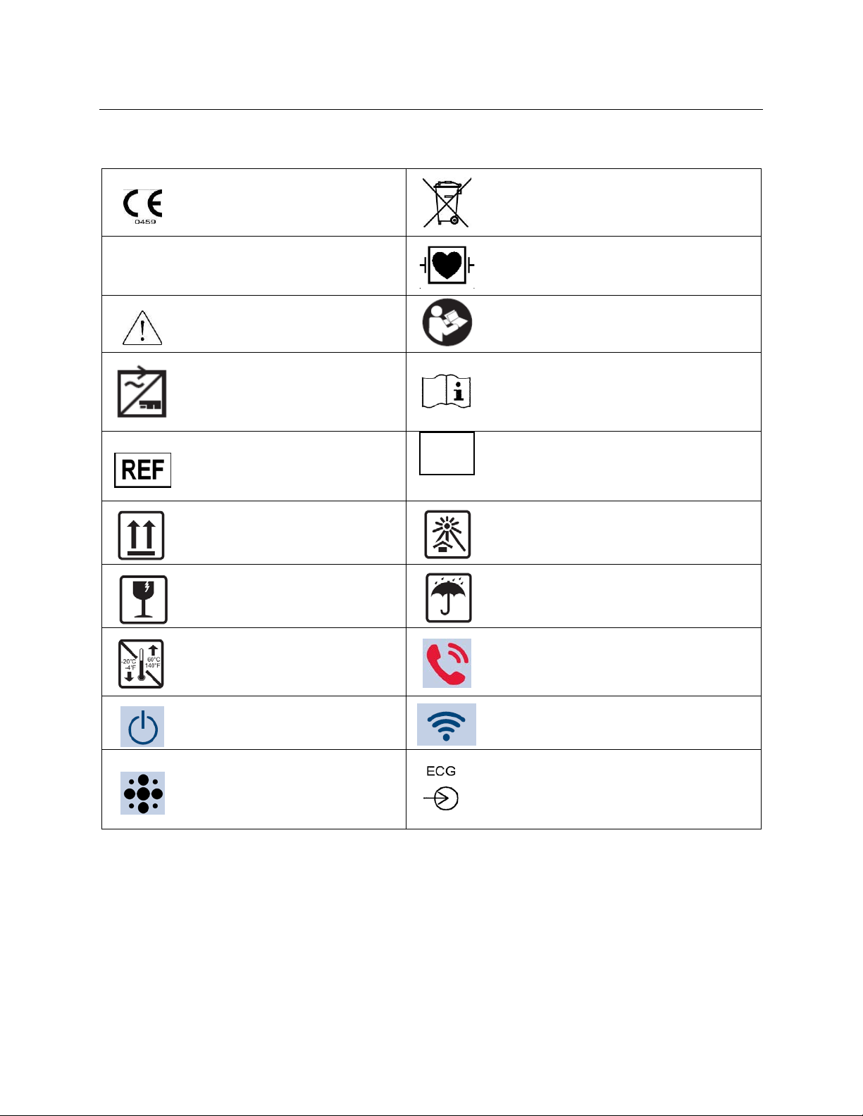
EQUIPMENT SYMBOLS AND MARKINGS
according to national requirements
Indicates the device has been tested
the enclosure from any direction
SN
Do not dispose as unsorted municipal waste.
Indicates compliance to applicable
European Union directives
Per European Union Direc tiv e 2002/ 96,
requires separate handling for w aste dispos al
IPX4
for safety and shall have no harmful
effect from water splashing against
Caution
Mains power input
Catalog number for relevant Mortara
part
This end up
Fragile, handle with care
Temperature limitation
Defibrillator-proof type CF applied part
Consult accompanying documents
Consult instructions for use
Serial number
Keep away from sunlight
Keep dry
Nurse Call/Control Button
The illuminated LED below this icon
indicates the Power On/Off status
Speaker
(RESERVED FOR FUTURE USE)
11
The illuminated LED below this icon indicates
the status of the WiFi connection
Patient Cable Input
Page 20

ELECTROMAGNETIC COMPATIBILITY (EMC)
When using the mobile monitor, assess the electromagnetic environment affected by surrounding devices.
An electronic device may either generate or receive electromagnetic interference. Testing for electromagnetic
compatibility (EMC) has been performed on the mobile monitor according to the applicable international standards.
The mobile monitor sho uld not be used adjacent to or stacked with other eq ui pment. If the mobile monitor is used
in this manne r, verify the mobile monitor operates in an acceptable manner in the configuration in which it will be
used.
Fixed, portable, and mobile radio frequency communications equipment may affect the performance of medical
equipment. See the appropriate EMC table for recommended separation distances between the radio equipment and
the mobile monitor.
The use of accessories, transducers, and cables other than those specified by Mortara may result in increased
emissions or decreased immunity of the equipment.
12
Page 21
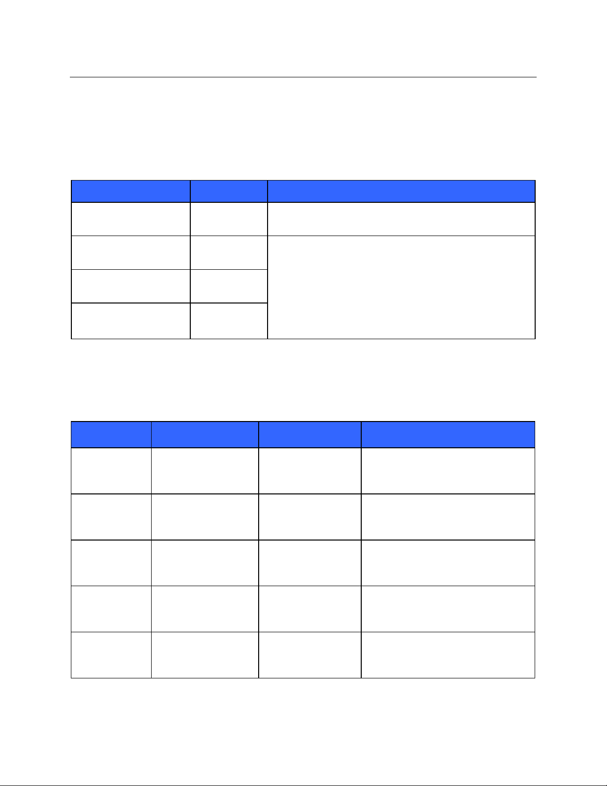
RF Emissions
Group 2
The S4 must emit electromagnetic energy in order to perform its
RF Emissions
Class A
The S4 is suitable for use in all establishments other than
Harmonic Emissions
Not Applicable
Voltage Fluctuations/
IEC 61000-3-3
Not Applicable
Electromagnetic Environment:
Guidance
Electrostatic
+/- 6 kV contact
+/- 6 kV contact
Floors should be wood, concrete, or
should be at least 30%.
Electrical fast
+/- 2 kV for
input/output lines
+/- 2 kV for
input/output lines
Mains power quality should be that of a
Surge
+/- 1 kV differential
+/- 1 kV differential
mode
Mains power quality should be that of a
Voltage
<5% UT for 0.5 cycles
<5% UT for 5s
<5% UT for 0.5 cycles
<5% UT for 5s
Note that monitoring is interrupted at the
EN 60601-1-2).
Power frequency
IEC 61000-4-8
3 A/m
3 A/m
Power frequency magnetic fields should
hospital environment.
ELECTROMAGNETIC COMPATIBILITY (EMC)
Guidance and Manufacturer’s Declaration: Electromagnetic Emissions
The equipment is intended for use in the electromagnetic environment specified in the table below. The customer or
the user of the equipment should ensure that it is used in such an environment.
Emissions Test Compliance Electromagnetic Environment: Guidance
CISPR 11
CISPR 11
IEC 61000-3-2
Flicker Emissions
intended function. Nearby electron ic equi pm ent may be affected
domestic and those directly connected to the public low-voltage
power supply network that supplies buildings used for domestic
purposes.
Guidance and Manufacturer’s Declaration: Electromagnetic Imm unity
The equipment is intended for use in the electromagnetic environment specified in the table below. The customer or
the user of the equipment should ensure that it is used in such an environment.
Immunity Test IEC 60601 Test Level Compliance Level
discharge (ESD)
EN 61000-4-2
+/- 8 kV air
+/- 8 kV air
ceramic tile. If floors are covered with
synthetic material, the relative humidity
transient/burst
EN 61000-4-4
IEC 61000-4-5
fluctuations and
Interruptions
(50/60 Hz)
magnetic field
NOTE: UT is the AC Mains voltage prior to application of the test level.
power supply lines
+/- 1 kV for
mode
+/- 2 kV common mode
40% UT for 5 cycles
70% UT for 25 cycles
power supply lines
+/- 1 kV for
mode
+/- 2 kV common
40% UT for 5 cycles
70% UT for 25 cycles
typical commercial or hospital
environment.
typical commercial or hospital
environment.
level “< 5% UT for 5s”, but equipment
remains safe (as specified in
be at levels characteristic of a typical
location in a typical commercial or
13
Page 22
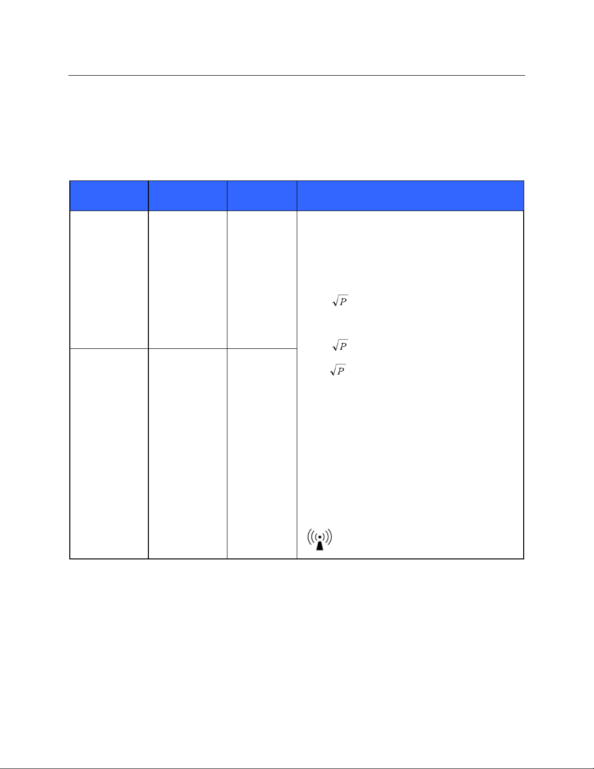
IEC 60601 Test
Compliance
Portable and mobile RF communications equipment
ELECTROMAGNETIC COMPATABILITY (EMC)
Guidance and Manufacturer’s Declaration: Electromagnetic Immunity
The equipment is intended for use in the electromagnetic environment specified in the table below. The customer or
the user of the equipment should ensure that it is used in such an environment.
Immunity Test
Conducted RF
EN 61000-4-6
Radiated RF
IEC 61000-4-3
Level
3 Vrms
150 kHz to
80 MHz
3 V/m
80 MHz to
2.5 GHz
Level
3 Vrms
150 kHz to
80 MHz
3 V/m
80 MHz to
2.5 GHz
Electromagnetic Environment: Guidance
should be used no closer to any part of the equipment,
including cables, than the recommended separation
distance calculated from the equation applicable to the
frequency of the transmitter.
Recommended separation dist anc e
d = 1.2
d = 1.2
d = 2.3
Where P is the maximum output power rating of the
transmitter in watts (W) according to the transmitter
manufacturer and d is the recommended separation
distance in meters (m).
Field strengths from fixed RF transmitters, as
determined by an electromagnetic site surveya, should
be less than the compliance level in each frequency
rangeb.
Interference may occur in the vicinity of equipment
marked with the following symbol:
80 MHz to 800 MHz
800 MHz to 2.5 GHz
a. Field strengths fro m fixed transmitters, suc h as base stations for radio (cellular/cordless) telephones and land
mobile radios, amateur radios, AM and FM radio broadcast, and TV broadcast cannot be predicted theoretically
with accuracy. To assess the electromagnetic environment due to fixed RF transmitters, an electromagnetic site
survey should be considered. If the measured field strength in the location in which the equipment is used
exceeds the applicable RF compliance level above, the equipment should be observed to verify normal operation.
If abnormal performance is observed, additional measures may be necessary, such as reorienting or relocating the
equipment.
b. Over the frequency range 150 kHz to 80 MHz, field strengths should be less than [3] V/m.
14
Page 23
ELECTROMAGNETIC COMPATIBILITY (EMC)
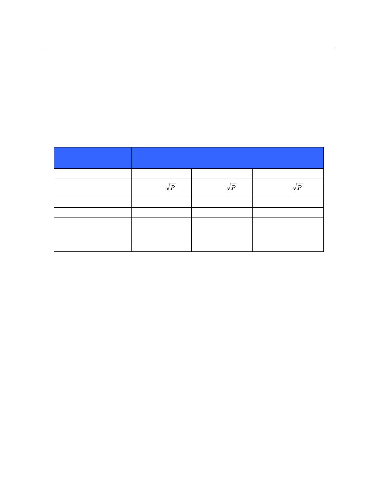
Recommended Separation Distances Between Port able and M obile RF Communications Equipment and the Equipment
The equipment is intended for use in the electromagnetic environment in which radiated RF disturbances are
controlled. The customer or the user of the equipment can help to prevent electromagnetic interference by
maintaining a minimum distance between portable and mobile RF communications equipment (transmitters) and the
equipment as recommended in the table below, according to the maximum output power of the communications
equipment.
Rated Maximum Output
Power of Transmitter (W)
150 KHz to 80 MHz 80 MHz to 800 MHz 800 MHz to 2.5 GHz
0.01 0.12 m 0.12 m 0.23 m
0.1 0.38 m 0.38 m 0.73 m
1 1.2 m 1.2 m 2.3 m
10 3.8 m 3.8 m 7.3 m
100 12.0 m 12.0 m 23.0 m
Separation Distance According to Frequency of Transmitter (m)
d = 1.2
d = 1.2 d = 2.3
For transmitters rated at a maximum output power not listed above, the recommended separation distance d in
meters (m) can be estimated using the equation applicable to the frequency of the transmitter, where P is the
maximum output power rating of the transmitter in watts (W) a cc ording to the transmitter manufacturer.
NOTE: At 80 MHz and 800 MHz, the separation distance for the higher frequency range applies.
NOTE: These guidelines may not apply in all situations. Electromagnetic propagation is affected by
absorption and reflection from structures, objects, and people.
15
Page 24

ELECTROMAGNETIC COMPATABILITY (EMC)
USA and Canada Radio Regulations
USA (FCC)
This device is equipped with Transmitter Module with FCC ID:RYYWYS AA V DX 7.
This device complies with part 15 of the FCC Rules. Operation is subject to the following two conditions:
(1) This device may not cause harmful interference, and
(2) This device must accept any interference received, including interference that may cause undesired operation.
CAUTION: Changes or modifications not expressly approved by the party responsible for
compliance could void the user’s authority to operate the equipment.
This device with transmitter module has been tested to SAR and complies with FCC exposure requirements for
portable devices. SAR testing has been done at a distance of 10mm from the face and 0mm from the body.
Canada (IC)
This device is equipped with Transmitter Module with IC:4389B-WYSAAVDX7.
This device complies with Industry Canada license-exempt RSS standard(s).
Operation is subject to the following two conditions:
(1) This device may not cause interference, and
(2) This device must accept any interference, including interference that may cause undesired operation of the
device.
This device with transmit te r module has been tested to SAR and complies with IC exposure requirements for
portable devices. SAR testing has been done at a distance of 10mm from the face and 0mm from the body.
French Translati on
Cet appareil est équipé d'un module émetteur avec marque IC:4389B-WYSAAVDX7
L’appareil conforme aux CNR d'Industrie Canada applicables aux appareils radio exempts de licence.
L'exploitation est autorisée aux deux conditions suivantes:
(1) l'appareil ne doit pas produire de brouillage, et
(2) l'appareil doit accepter tout brouillage radioélectrique subi, même si le brouillage est susceptible d'en
compromettre le fonctionnement.
Cet appareil avec module émetteur a été testé pour les taux d'absorption spécifique (DAS) et est conforme aux
normes d'exposition d'IC pour les appareils portables. Tests de DAS ont été réalisés à une distance de 10mm du
visage et du corps 0mm.
16
Page 25

ELECTROMAGNETIC COMPATIBILITY (EMC)
17
Page 26
MAINTENANCE & CLEANING
Warning: Servicing of this device should only be performed by Mortara authorized service
personnel.
Equipment needed:
• Clean lint free cloth
• Mild detergent and water
• 10% Household bleach and water solution (Sodium Hypochlorite solution consisting of a minimum 1:500
dilution and maximum of 1:10 dilution for disinfecting use only)
Preventive Maintenance Sch edule
Maintenance to be Performed Period Notes
Device Cleaning As Needed Refer to the device cleaning section below.
SECTION 2
Visual Inspection 12 Months
Battery Door Replacement 36 Months
Refer to inspection criteria list e d in Visual Inspection
section.
Replacement period varies based on frequency of use;
refer to visual inspection criteria for areas of concern.
Visual Inspection
Perform a visual inspection of the following items:
Patient input connector - Verify the pins on the patient input connector are all present and are not bent or damaged
in any way. The recessed area for the patient connector should be free from debris and clean. Use compressed air to
remove any debris that has entered into the connector area.
Display – Verify there are no deep scratches or physical damage to the device display. Inspect the display bezel to
ensure it is firmly adhered to the device housing. Contact Mortara technical support if the display or display bezel
require replacement.
Battery Door – Verify the battery door can be easily removed and that the spring contacts compress and
decompress with minimal force applied. Inspect the plastic door assembly for signs of excessive wear or cracking,
including the door seal t o prevent fluid ingress. Rep lace the battery door assembly if necessary.
Battery Compartment – Inspect the battery spring contacts and the battery door latching mechanism for signs of
excessive wear. If the battery compartment has been damaged, contact Mortara technical support for assistance.
Device Labeling – Inspect the device labeling for signs of wear and legibility. If the labeling is no longer clear and
legible, contact Mortara technical support for assistance.
18
Page 27

MAINTENANCE & CLEANING
SECTION 2
Cleaning and Disinfecting
The following section provide s in formation on proper cleaning direction s for the S4, patient accessories, Li-Ion
battery Charger, AC Power Pack and AC Power Cord. Patient accessories should be cleaned before they are applied
to a new patient. The mobile monitor should be cleaned as per facility standard of care. The Li-Ion battery Charger,
AC Power pack and AC Power Cord should be cleaned in accordance with facility standards pertaining to power
components.
Warnings:
• Remove the batteries from the device before inspecting or cleaning.
• Do not immerse the device in water or other fluids.
• Do not drop the device or subject it to shock and/or vibration.
• Do not use organic solvents, ammonia-based solutions, or abrasive cleaning agents which may
damage equipment surfaces.
• Be careful not to use an excessive amount of disinfecting solution that could lead to fluid entering the
device. Fluid ingress may cause irreparable damage to the internal circuitry.
Cautions:
• Always disconnect the S4 from power source before cleaning.
• Do not use harsh chemicals for cleaning. Do not use disinfectants that contain phenol as they can spot
plastics. Do not steam autoclave, gas ster iliz e , irradiate, subject to intense vacuum, or immerse in
water or cleaning solution. Be careful to avoid getting cleaning liquids into c onnectors or the mobile
monitor. If this occurs, allow the mobile monitor to dry in warm air for 2 hours, then check to make
sure all monitoring functions are working properly.
• Keep the patient accessories off of the floor. Accessories that fall on the floor should be inspected for
defects, contamination, proper functionality, and cleaned or discarded according to the approved
recommendations.
• The user has the responsibility to validate any deviations from the recommended method of cleaning
and disinfection.
Clean the exterior surface of the device and patient cables with a mild soap and water solution. After cleaning
thoroughl y dry off the device with a clean, lint-free, soft cloth.
Disinfect the device after cleaning the exterior surface as required. To disinfect the device wipe the exterior surface
with a damp, soft, lint-free cloth using a solution of 10% household bleach and water (Sodium Hypochlorite solution
consisting of a minimum 1:500 dilution and maximum of 1:10 dilution). Dry off the device with a clean, lint-free,
soft cloth.
19
Page 28
quid and doing so may result in liquid entering the device leading to possible safety hazards and/or device
Do not steam autoclave, gas sterilize, or irradiate the S4 as these may result in damage to the
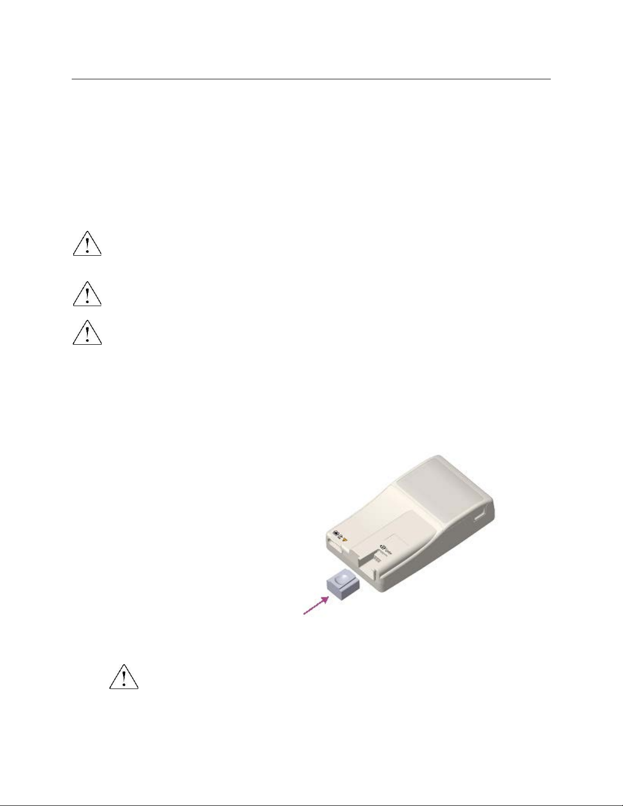
Press the SpO2 wash plug into the SpO2
port until the top of the plug is flush wit h
the top
excessive force. If the plug resists
insertion, check the port for obstr uctions
and/or check the wash plug to ensure it has
not been deformed.
Disinfecting agents
The S4 and its Li-ion battery charger are compatible with the following disinfectants:
®
• Clorox Healthcare
• a soft, lint-free cloth dampened with a solution of sodium hypochlorite (10% household bleach and water
solution) minimum 1:500 dilution (minimum 100 ppm free chlorine) and maximum 1:10 dilution as
recommended by the APIC Guidelines for Selection and Use of Disinfectants.
Cleaning and disinfecting the S4 monitor
WARNING: Do not immerse the S4 in water or any other fluids. The S4 is not designed to be immersed in
li
malfunction.
CAUTION:
device.
WARNING: Ensure the battery door is securely in place when cleaning the S4 to avoid risk of liquid
entering into the device which may lead to a possible hazard and/or device malfunction.
Bleach Germicidal Wipes (use according to instructions on product label), or
SECTION 2
To clean the S4:
1. Switch off the touchscreen display. If on, press the Nurse Call button once to turn off the display
2. Disconnect patient cables from the S4.
3. If the S4 is configured with the SpO
surface of the S4. Do not apply
4. Thoroughly wipe the surface of the S4 with a clean, lint-free cloth dampened with water for general
cleaning, or use one of the above recommended agents for disinfection.
WARNING: Do not oversaturate the cleaning cloth. Liquid pooling on the device may enter into
the device possibly leading to a safety hazard and/or device malfunction.
5. Dry the device with a clean, soft, dry, lint-free cloth.
option, install the SpO2 wash plug in the SpO2 port.
2
complete
20
Page 29
MAINTENANCE & CLEANING
The charger is not designed
Functionality
Procedure
• Connect ECG leads to Patient Simulator.
• Verify that waveforms for all leads are properly shown on the LCD.
Cleaning and disinfecting the Li-ion battery charger
WARNING: Do not immerse the battery charger in water or any other fluids.
to be immersed in liquid and doing so may result in liquid entering the device leading to possible safety
hazards and/or device malfunction.
CAUTION: Do not steam autoclave, gas sterilize or irradiate the battery charger as these may result in
damage to the device.
1. Disconnect the AC power cord from the mains supply.
2. Thoroughly wipe the surface of the battery charger with a clean, lint-free cloth dampened with water for
general cleaning, or use one of the above recommended agents for disinfection.
WARNING: Do not oversaturate the cleaning cloth. Liquid pooling on the device may enter into
the device possibly leading to a safety hazard and/or device malfunction.
3. Dry the device with a clean, soft, lint-free cloth.
4. Allow the equipment to d ry for 2 hours before reconnecting to the mains supply.
Cleaning sensors and other acces sories
The S4 is compatible with a number of sensors and accessories, each with unique cleaning needs. Follow the
cleaning instructions provided in the directions for use shipped with those items.
SECTION 2
WARNING: Do not reuse sensors or accessories indicated as single-patient use; as this may facilitate the
spread of infectious agents between persons.
WARNING: Always clean and/or disinfect reusable sensors and accessories between patients to reduce
the risk of spreading infectious agents between persons.
Maintenance
The following table shows the recommended maintenance procedures for the S4, patient accessories, Li-Ion Battery
Charger, AC Power Pack and AC Power Cord. The S4 should be serviced once a year by a Mortara authorized
service technician; however, it is good practice to periodically ensure the mobile monitor is in proper working order.
This can be performed by a clinician or biomed at the hospital or healthcare delivery organization familiar with the
S4 mobile monitor, ECG signal acquisition, as well as general maintenance/calibra tion of biomedical equipment.
To accomplish these steps in their entirety and verify the correct operation of the system, appropriate patient
simulators or other equipment may be required.
Mechanical Integrity Check for cracks, abrasive edges and other signs of damage.
ECG
• Start a new monitoring session.
Refer to the service manual for further details.
21
Page 30

Functionality
Procedure
• Check for cracks, abrasive edges and other signs of damage.
• Verify proper LED indicators during battery charging.
ECG Cables
Approved Cleaning Agents
11. Allow 2 hours for drying.
SECTION 2
Li-Ion Battery Charger,
AC Power Pack, AC
Power Cord
• Check that all connectors and AC cord length is unbroken and smooth along its
length.
• Enzymatic detergent such as ENZOL (US) or CIDEZYME (outside the US).
• Distilled water.
• Disinfectant solution (such as CIDEX OPA, or a 10% solution of household
bleach (5.25% sodium hypochlorite) in distilled water).
• Soft, lint-free cloths and/or soft-bristled brushes.
• Protective gloves and eyewear.
Procedure
1. Disconnect the mobile monitor from its power source.
2. Put on gloves and protective eyewear.
3. Prepare the detergent according to the manufacturer's instructions, and also
the disinfectant solution, in separate co ntainers.
4. Apply detergent to product using a soft, lint-free cloth. If material is dried on,
allow to sit for 1 minute. Do not immerse cable ends or lead wires in liquid as
it can cause corrosion.
5. Wipe smooth surfaces with the cloth.
6. Use a soft-bristle brush on visibly soiled areas and irregular surfaces.
7. Remove detergent from product using cloth dampened in distilled water.
8. Repeat as necessary.
9. Apply disinfectant solution on affected area using a soft cloth. Allow product to
sit for 5 minutes.
10. Wipe excess solution and clean product again with cloth dampened in distilled
water.
22
Page 31
UNIT DISASSEMBLY
SECTION 3
This section describes the methods used to disassemble both the generation 1 S4 and the generation 2 S4 mobile
monitor, and the tools required to perform the steps defined.
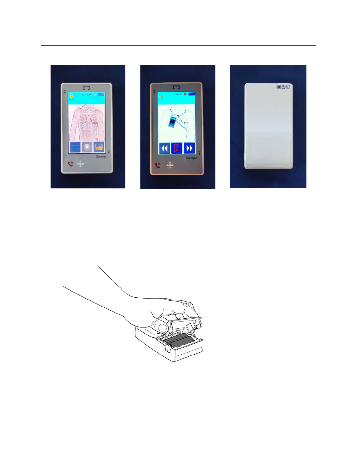
The generation 1 S4 can be identified by the flat smooth call button or by PN: S4-P-B.
The generation 2 S4 unit can be identified by the indented call button surrounded by a raised ring
or by PN:S4-Q-XXX-XXX.
Tools Required:
• Phillips screwdriver
• T10 Torx driver
• Torque driver (2 inch/pounds)
• Needle nose pliers
Cautions and Special Instructions
ATTENTION: P CB assembly contains ESD sensitive devices. Use appropriate precautions when
handling electronic assemblies.
ATTENTION: P CB assembly contains mechanically sensitive electrical devices. Handle with extreme
care to reduce the stress on solder connections.
ATTENTION: Before ap p lying all adhesive backed materials, clean surface with alcohol to make sure it
is clean and oil free.
23
Page 32
S4 Mobile Monitor – Gen 1 (Front
View)
S4 Mobile Monitor – Gen 2
(Front View)
S4 Mobile Monitor (Rear View)
SECTION 3
Battery Removal
The battery compartment is accessible via the removable battery door.
1. Remove the Battery Door by pinching the grips located on each side of the door and remove.
24
Page 33
1 2 15
SECTION 3
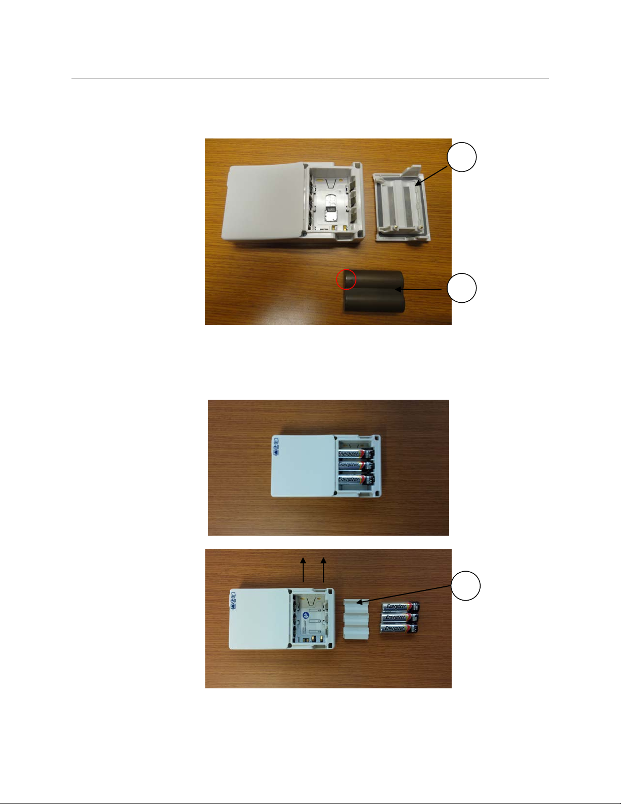
2. With the battery door assembly (item 1) removed, the battery can be slid away from the battery contacts, in the
opposite direction of the battery insertion arrow marked on the lithium-ion battery pack (item 2 shown below).
AA Battery removal – Remove the three AA batteries. If the device will continue being operated with AA
batteries, the AA Battery Tray (Item 15) can remain inside the battery compartment. If switching to a lithiumion battery pack, the AA Battery Tray should be removed by sliding it in the direction indicated by the arrows
below.
25
Page 34
3
4/5
SECTION 3
SAM/Housing Removal
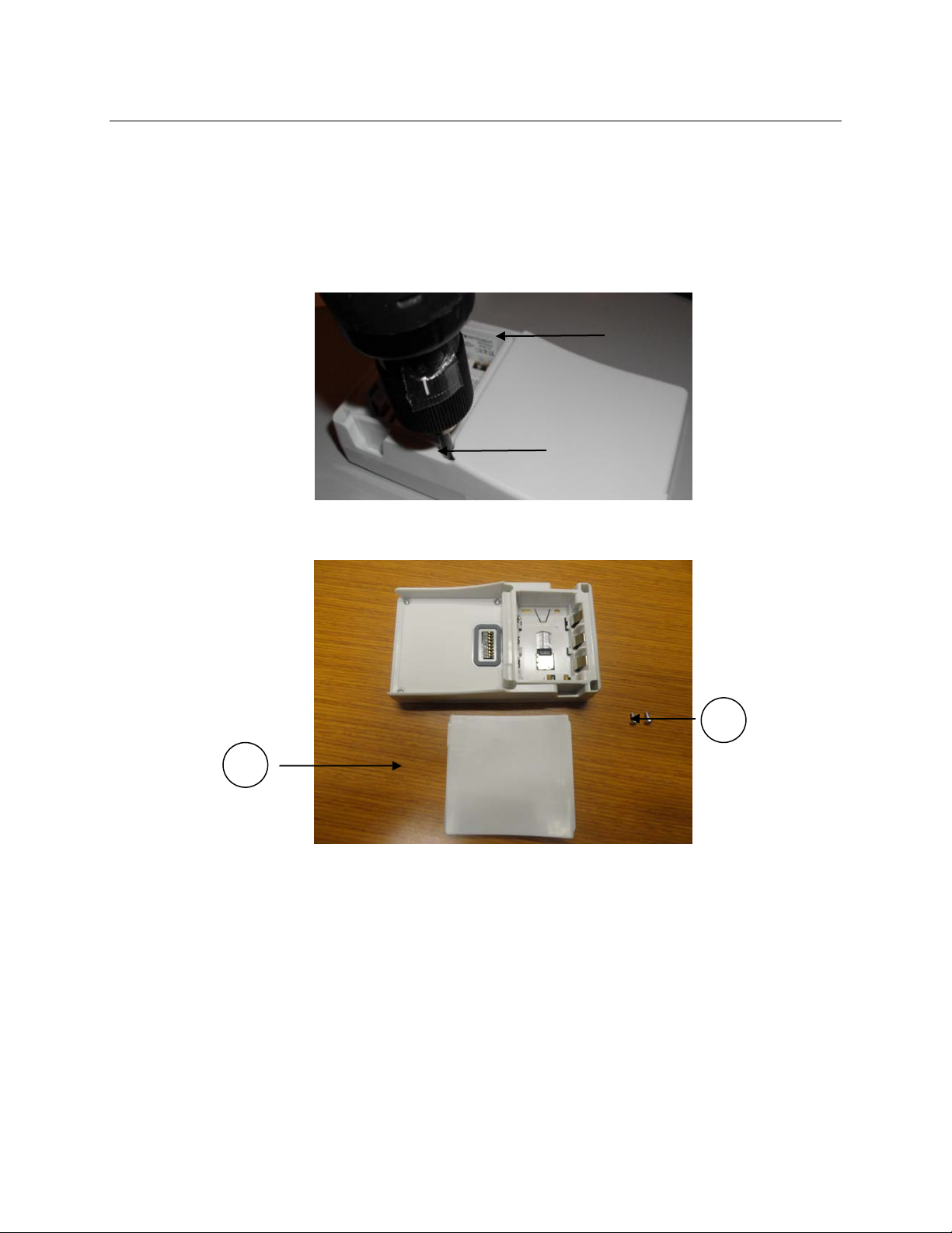
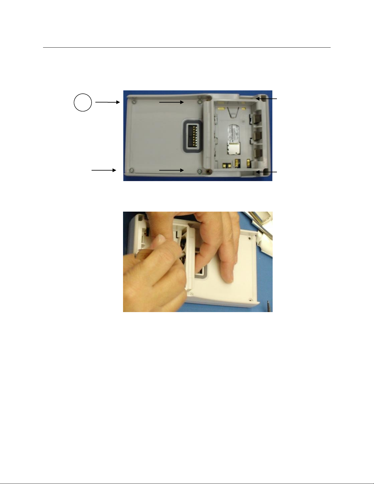
3. Remove t he Surveyor ECG Acquisiti on Module ( SAM) from t he unit by removing the two Phillips head screws
(item 3) from the recessed areas indicated below.
Screws should be installed to2 inch/pounds of torque.
4. Slide the SAM from the device housing as shown below.
26
Page 35
6
SECTION 3
5. Remove the six (6) Torx housing screws (item 6) from the areas indicated below.
Screws should be installed to 2 inch/pounds of torque.
6. Using a needle nose pliers or tweezers, carefully guide the battery springs and contacts through the housing
openings as shown belo w.
27
Page 36
S4 PCBA – Gen 1
S4 PCBA – Gen 2
S4 PCBA – Gen 1
S4 PCBA – Gen 2
7
SECTION 3
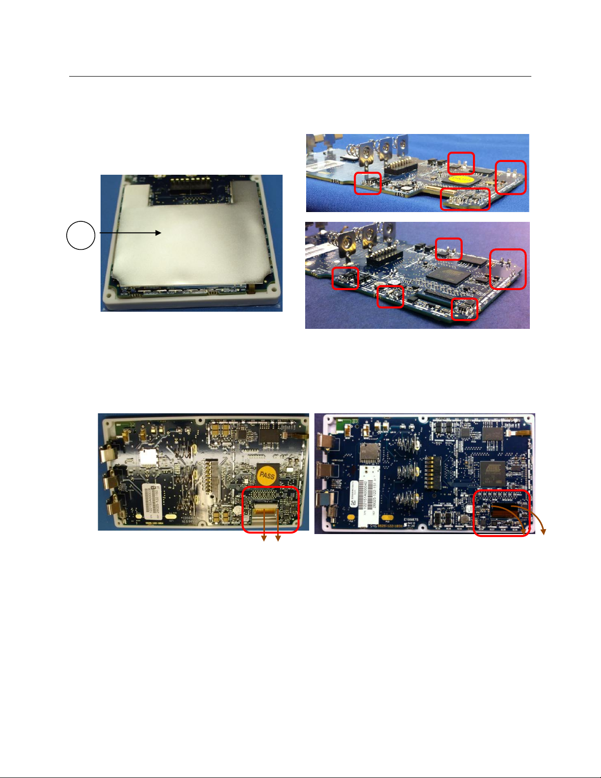
7. Carefully remove the Shield C an (item 7), which is held in place by shield can retention clip s mounted to the
edge of the PCBA and retain it for reassembly.
8. Remove the wider ribbon cable of LCD assembly by gently moving the latc h mechanism in the direction of the
arrows with a tweezers.
28
Page 37
S4 PCBA – Gen 1
S4 PCBA – Gen 2
SECTION 3
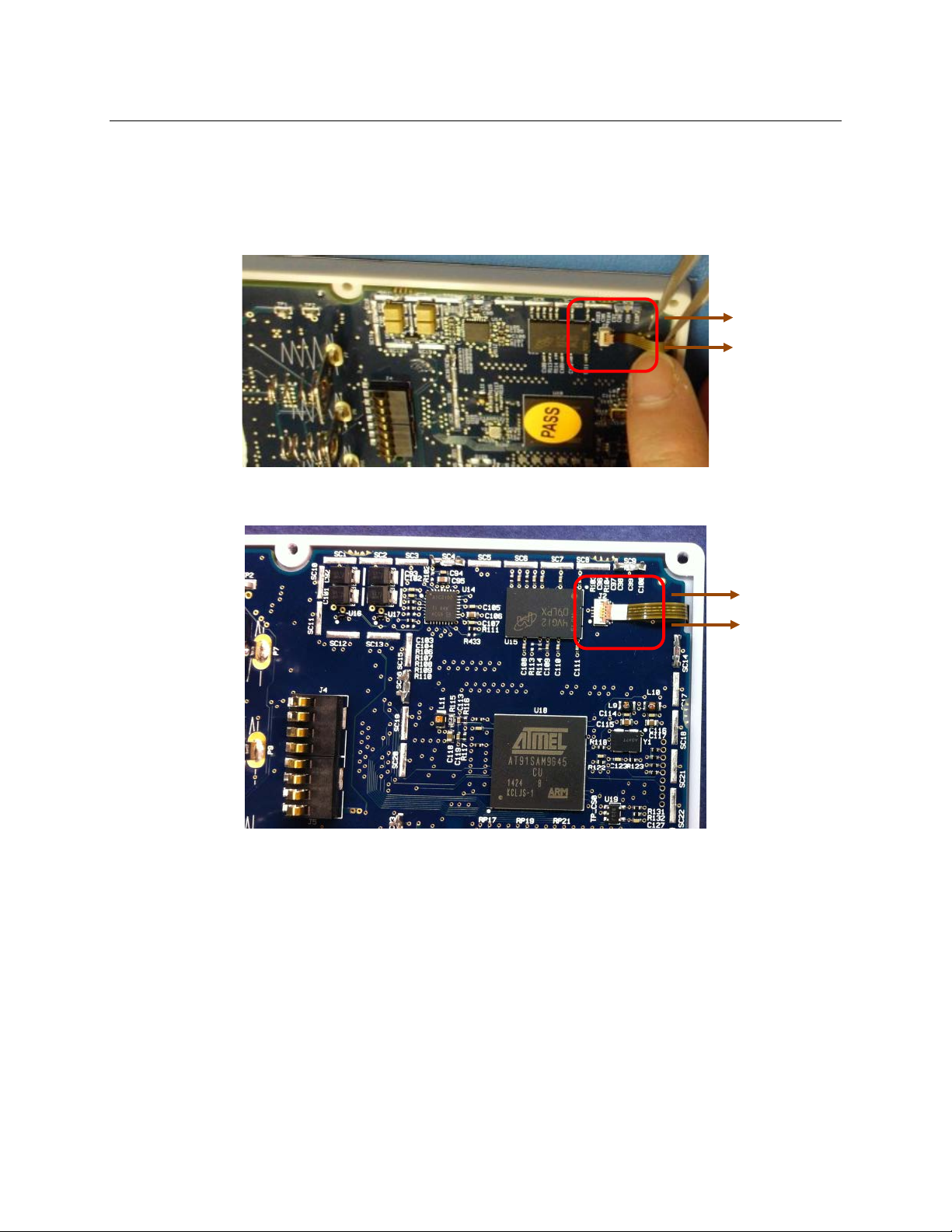
9. Remove the narrow rib bon cable of LCD assembly by gently mo ving the latc h mechanism i n the directio n of
the arrows with a tweezers.
29
Page 38
Main PCBA – Gen 1
Main PCBA – Gen 2
Display Assembly – Gen 1
Display Assembly – Gen 2
8a
9a
8b
9b
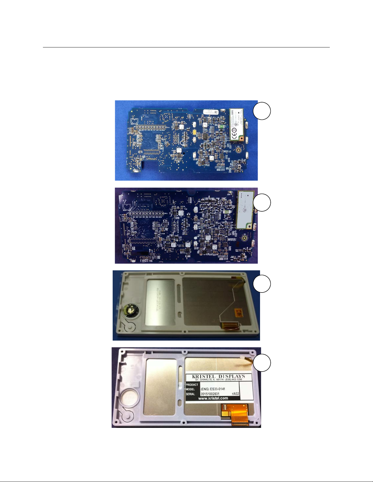
PCBA Replacement
10. Remove the printed circuit board assembly (PCBA – item 8) from the display ass embly (item 9).
SECTION 3
30
Page 39
1
76190-002-70
S4 BATTERY DOOR QI CHARGE CAPABLE
2
4800-018
BATTERY LI-ION 7.4V 1600mAh
3
6020-031
SCREW PHILLIPS M2.5X6
4a
*SERV 76190-002-50
S4 10-WIRE SAM GEN1 - TESTED
5a
*SERV 76190-002-60
S4 3/4/5 WIRE SAM GEN1 - TESTED
6
6020-066
SCREW THD-FORM PAN HD TORX K25X1.12X6mm
7
8312-033-01
SHIELD CAN
8a
*SERV 26025-122-150
S4 MAIN PCB GEN 1 – w/RADIO,NO SD CARD
9a
*8364-001-51
LCD + TOUCHPANEL w/200MP ADHESIVE S4 GEN1
10
8364-002-51
HOUSING MAIN + GASKETS
11a
*11083-002-51
S4 V1.01 uSD MEM CARD GEN1 W/ SERV CONF
11b
11083-003-51
S4 V1.1.0 uSD MEM CARD ASSY W/ SERV CONF
12
9042-082-07
LABEL PRODUCT SURVEYOR S4
13
9042-082-10
LABEL BATTERY SURVEYOR S4
14
9910-025-50
WLAN RADIO MODULE WITH ADHESIVE
15
8364-005-50
TRAY AA BATTERY SURVEYOR S4
SECTION 3
The items listed in the S4 GEN1 mobile monitor item description listing identify the serviceable level of the device.
Subcomponents of assemblies listed are not available as individual service items from Mortara, the assembly level
item must be used for servicing purposes.
S4 GEN1 Mobile Monitor Item Description Listing
(GEN 1 units can be identified by PN: S4-P-x)
Item # Part # Description
(*) indicates Part # is not compatible with the S4 GEN2
31
Page 40
1
76190-002-70
S4 BATTERY DOOR QI CHARGE CAPABLE
2
4800-018
BATTERY LI-ION 7.4V 1600mAh
3
6020-031
SCREW PHILLIPS M2.5X6
4b
**SERV 76190-002-51
S4 10-WIRE SAM GEN2 -TESTED
4c
**SERV 76190-002-100
S4 10-WIRE SpO2 SAM GEN2 -TESTED
5b
**SERV 76190-002-61
S4 5-WIRE SAM GEN2 - TESTED
5c
**SERV 76190-002-110
S4 5-WIRE SpO2 SAM GEN2 - TESTED
6
6020-066
SCREW THD-FORM PAN HD TORX K25X1.12X6mm
7
8312-033-01
SHIELD CAN
8b
**SERV 26025-122-151
S4 MAIN PCB GEN 2 – w/RADIO,NO SD CARD
9b
**8364-001-52
LCD + TOUCHPANEL STRENGTHENED S4 GEN 2
10
8364-002-51
HOUSING MAIN + GASKETS
11b
11083-003-51
S4 V1.1.0 uSD MEM CARD ASSY W/ SERV CONF
11c
**11083-004-51
S4 V1.2.0 uSD MEM CARD GEN2 W/ SERV CONF
12
9042-082-07
LABEL PRODUCT SURVEYOR S4
13
9042-082-10
LABEL BATTERY SURVEYOR S4
14
9910-025-50
WLAN RADIO MODULE WITH ADHESIVE
15
8364-005-50
TRAY AA BATTERY SURVEYOR S4
SECTION 3
The items listed in the S4 GEN2 mobile monitor item description listing identify the serviceable level of the de vice.
Subcomponents of assemblies listed are not available as individual service items from Mortara, the assembly level
item must be used for servicing purposes.
S4 GEN2 Mobile Monitor Item Description Listing
(GEN 2 units can be identified by PN: S4-Q-xxx-xxx)
Item # Part # Description
(**) indicates Part # is not compatible with the S4 GEN1
32
Page 41
SERV 76190-002-50
SERV 76190-002-60
SERV 26025-122-150
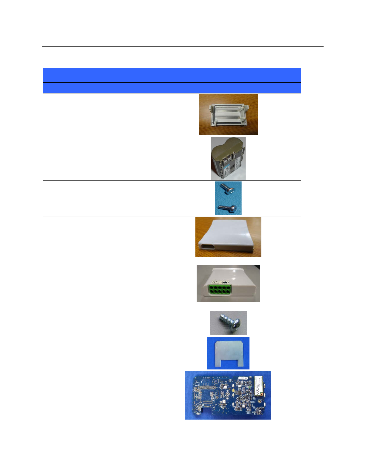
S4 Mobile Monitor Item Identification Table
Item # Part # Picture
1 76190-002-70
2 4800-018
3 6020-031
SECTION 3
4a
4b
4c
5a
5b
5c
6 6020-066
7 8312-033-01
8a
8b
SERV 76190-002-50
SERV 76190-002-51
SERV 76190-002-100
SERV 76190-002-60
SERV 76190-002-61
SERV 76190-002-110
SERV 26025-122-150
SERV 26025-122-151
33
Page 42
(includes label with “11083-002-51” item #)
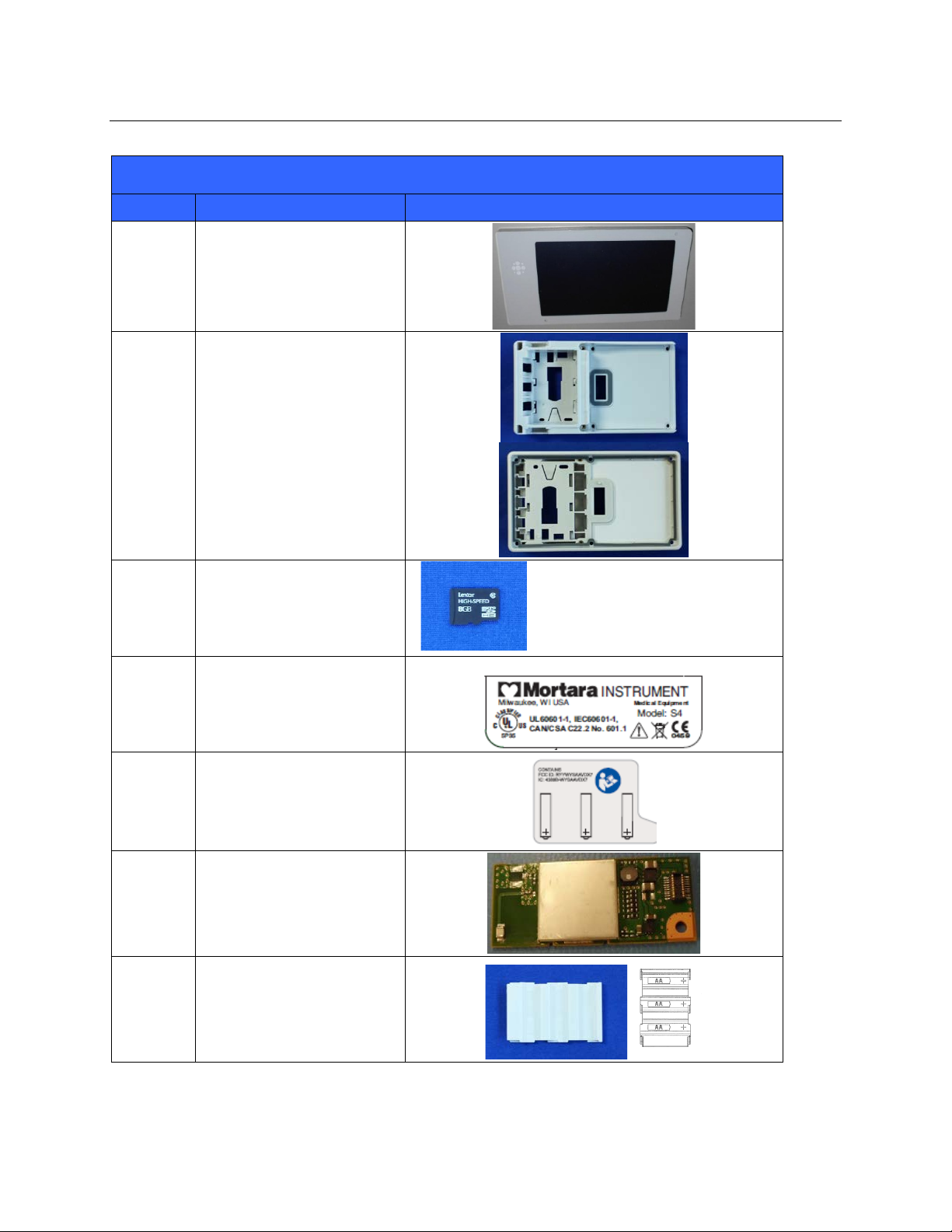
S4 Mobile Monitor Item Identification Table
Item # Part # Picture
SECTION 3
9a
9b
10 8364-002-51
11a
11b
11c
12 9042-082-07
8364-001-51 (Pictured)
8364-001-52
11083-002-51 (Pictured)
11083-003-51
11083-004-51
13 9042-082-10
14 9910-025-50
15 8364-005-50
34
Page 43

CONFORMANCE TESTING
SECTION 4
Conformance testing is to be performed by Authorized Mortara Service Representatives to verify the devic e is
functioni ng correctly after repair operations have been performed. Testing results should be documented on the test
data record at the end of this section of the manual.
Required Equipment
Functional Testing:
• Lithium-Ion battery
• 3 – AA batteries
• 8364-005-50 AA battery tray (if not i nstalled in unit)
• Touchscreen stylus
• Patient simulator
• ECG and SPO2 Patient cables (type dependent on model of S4)
• Surveyor Central with 4.1x or 4.3x or newer software and WLAN connectivity
• 11010-037-03 Rev xx S4 service utility software
• TF-0620 Lead Fail Test Fixture
IPX Vacuum Leak Testing:
• Vacuum Generator
• TF-0582 S4 battery door seal test fixture
• TF-0583 S4 IPX leak test fixture
Safety Testing:
• DC Hi-Pot Tester
• TF-0579 S4 Hi-Pot test fixture
• TF-0580 S4 Hi-Pot test fixture insert for 3, 4, 5-wire SAM
• TF-0581 S4 Hi-Pot test fixture insert for 10-wire SAM
• TF-0619 S4 Hi-Pot test fixture for 10 wire SAM
• TF-0633 S4 Hi-Pot test fixture insert for 3,5-wire SPO2 SAM
• TF-0634 S4 Hi-Pot test fixture insert for 10- wire SPO2 SAM
• TF-0643 Lead Shorting Test Fixture
Note: Portions of this sectio n will call out distinctive operation and testing differences between Generation 1 & 2
devices. Apply only those portions as they are applicable to the type of device being serviced.
35
Page 44

SECTION 4
Unit Vacuum Leak Test (IPX4 Rating)
Setup and verification of test equipment:
• Turn on vacuum generato r.
• Turn off the Vacuum switch on TF-0583.
• Turn off the B att Door and Main Unit switches on TF-0583.
• Verify the vacuum reads 35.0 +/- 5 in/H
• Turn on the Vacuum switch on TF-0583.
• Verify the gauge on TF-0583 reads 35.0 +/- 5 in/H
Test Process (for Unit Body)
• Connect TF-0582, to the vacuum hose of TF-0583 marked Main Housing.
• Turn on the vacuum gener ator.
• Turn ON the Vacuum switch on TF-0583.
• Connect TF-0582 to the main body of the unit under test.
• Verify the vacuum reading is 35.0 +/- 5 in/H
• Turn the Batt Door switch on TF-0583 to the ON position.
• Turn off the Vacuum switch on TF-0583 and then turn off the vacuum generator.
• Verify the time elapsed until the pressure gauge returns to ambient pressure is longer than 1 second.
If the press ure returns to ambient prior to 1 second, the UUT fails the test.
Switch the Vacuum switch on to release the vacuum pressure so the Plexiglas cover can be removed.
Test Process (for Battery Door)
• Turn off the B att Door and Main Unit switches on TF-0583.
• Turn on the vacuum gener ator.
• Place the battery door under test o nto Part of TF-0583 connected to the Main Unit vacuum hose.
• Turn ON the Vacuum switch on TF-0583.
• Verify the vacuum reading is 35.0 +/- 5 in/H
• Turn the Main Unit switch on TF-0583 to the ON position.
• Turn off the Vacuum switch on TF-0583 and then turn off the vacuum ge nerator .
• Verify the time elapsed until the pressure gauge returns to ambient pressure is longer than 1 second.
If the pressure returns to ambient pr ior to 1 second, the UUT fails the test.
Functional Testing
Power/LED Testing
Install a Lithium-Ion battery into the battery compartment and install the battery door. The Gen 1 device should
power up automatically, while the Gen 2 device will require the Call Button to be pressed to initiate power up. The
unit should indicate it is receiving power, by the power LED flashing green and the WiFi LED flashing blue.
The unit should momentarily display the Mortara logo, then power up to the main screen.
O on TF-0583 (adjust vacuum generator if necessary).
2
O (adjust if necessary).
2
O.
2
O.
2
36
Page 45
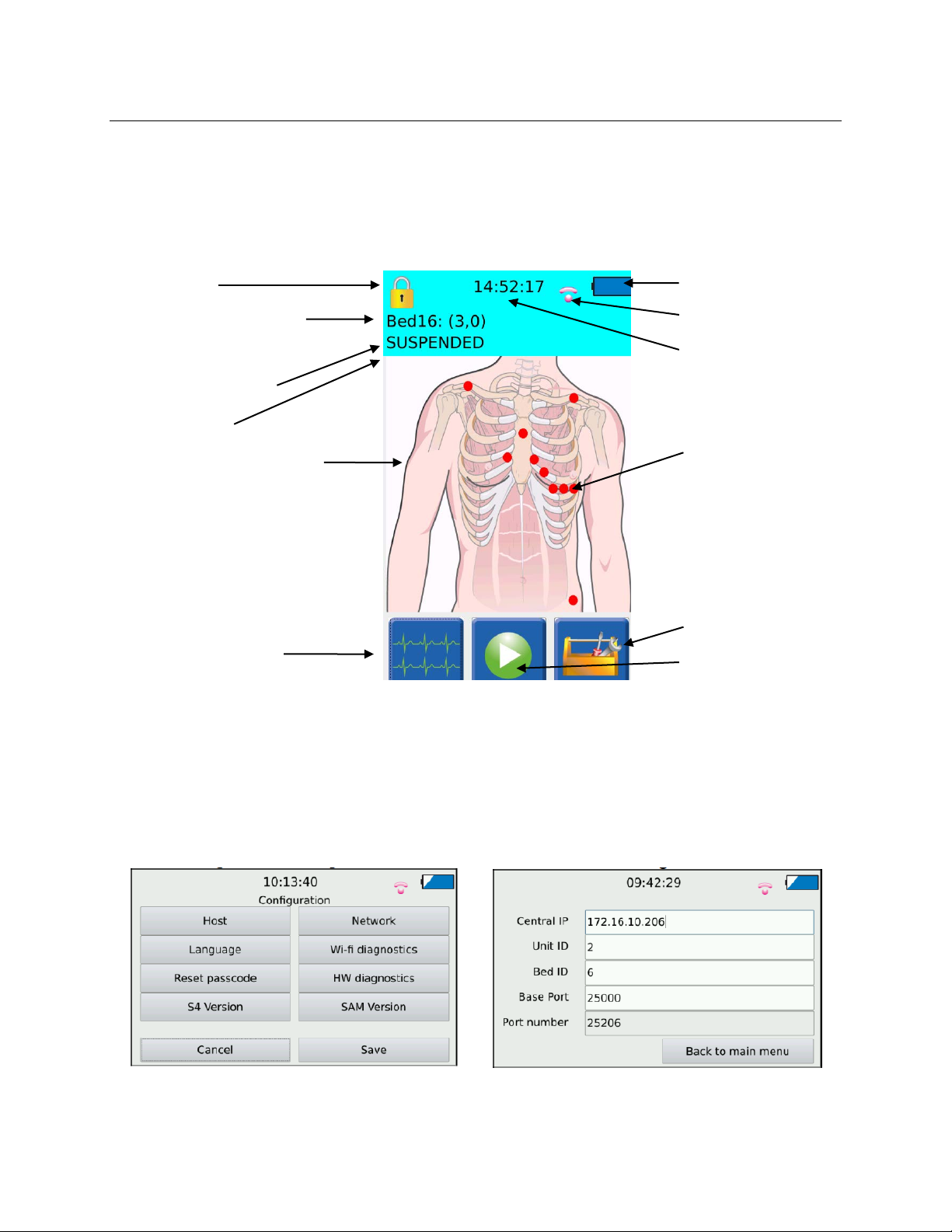
Lock Icon
Battery Level Indicator
Device Configuration Menu
Main Screen with Patient Hookup Display
Repeat the power up process using the AA battery tray and AA batteries.
Main Screen
The following diagram depicts the main screen of the S4 with the patient hookup display.
SECTION 4
Central Station Slot
Name (Unit ID & Bed
ID)
Monitoring Status
Status Area
Patient Hookup Display
Waveform Review
WiFi Connectivity Test
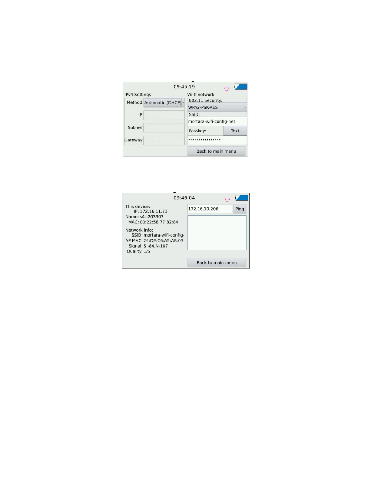
Access the Device Configuration Menu (password 7865) and select the Host button. Enter the hos t IP information,
Unit ID, and Bed ID for the Surveyor C entral station the S4 will be connecting to, then go back to the main menu.
WiFi Signal Strength
Current Time of Day
Lead Quality Indicators
Green: OK
Red: Off
Start Monitoring Menu
37
Page 46
SECTION 4
Press the Network button and enter the appropriate method for obtaining an IP address, IP address (if applicable),
and security information to connect to the Surveyor Central system. Return to the main menu.
Press the WiFi Diagnost ic s button to test the WiFi co nnection to the Surveyor Ce ntral system. Verify connectivity
is established and signal quality information is displayed.
Press the Ping button to perform a ping test to the Surveyor Central. Ve rify successful transmission of data occurs.
Return to main men u.
Verify Version Information
Access the Device Configuration Menu (password 7865) and select S4 Version to verify serial number, part number
and software version.
If device serial number and part number fields are blank follow instructions for EEPROM write, otherwise skip to
display test.
Eeprom Write
On the Surveyor Central System, t ype Ctrl+Shift+ESC to open Task Manager.
Select New Task.
Type CMD.exe into the open field and select OK to run the command prompt
Type cd and type in the file path the 11010-037 S4 Service and Utility Software is located to change the directory to
the S4 test software folder
Power on the S4
38
Page 47

SECTION 4
Access the Device Configuration Menu (password 7865) and access the Wi-fi diagnostics menu to find the S4 IP
address
In the cmd prompt type S4EepromWrite
When prompted to Insert S4 IP address/name: enter the IP address found previously on the S4 device
When prompted to Insert S4 Serial Number: enter the device serial number
When prompted to Insert S4 Part Number: enter the device part number
Press any key to exit and return to the dire c tory
Display Test (Gen 1 device only)
On the Surveyor Central System, type Ctrl+Shift+ESC to open Task Manager .
Select New Task.
Type CMD.exe into the open field and select OK to run the command prompt
Type cd and type in the file path the 11010-037 S4 Service and Utility Software is located to change the directory to
the S4 test software folder
Power on the S4
On the UUT Access the Device Configuration Menu (password 7865) and access the Wi-fi diagnostics menu to find
the S4 IP address
In the cmd prompt type S4LCDTest 1xxxxxxxxxxx (the IP address found previously on the S4 device)
A script will then run through the following LCD test displays:
Solid red display
Red gradient display
Solid blue display
Blue gradient display
Solid green display
Green gradient display
Solid white display
White gradient display
Black/white checker display
During these test displays watch the LCD display and note any missing pixels or unusual coloring.
After the test the CMD prompt will automatically return to the directo r y.
Display Test (Gen 2 device only)
On the UUT access the Service Test Utility Menu by pressing and holding the Call Button beyond the splash screen,
until the green cursor appears. Enter 5687 into the passcode field. Select LCD Test from the menu. Touch screen to
cycle through the following LCD test displays:
Solid blue display
Solid green display
Solid red display
Solid white display
Black/white checker display
Blue gradient display
Green gradient display
Red gradient display
White gradient display
During these test displays watch the LCD display and note any missing pixels or unusual coloring.
After the test, device automatic a lly reboots. Press and hold Call Button to return to Service Test Utility Menu to continue
onto Gen 2 Touch Screen Calibration.
39
Page 48

SECTION 4
Touch Screen Calibration (Gen 1 device only)
On the Surveyor Central System, type Ctrl+Shift+ESC to open Task Manager .
Select New Task.
Type CMD.exe into the open field and select OK to run the command prompt
Type cd and type in the file path the 11010-037 S4 Service and Utility Software is located to change the directory to
the S4 test software folder
Power on the S4
On the UUT, access the Device Configuration Menu (password 7865) and access the Wi-fi diagnostics menu to find
the S4 IP address
In the cmd prompt type S4ResetCalibration 1xxxxxxxxxxx (the IP address found previously on the S4 device).
A script will then run, resetting the touch screen calibration.
The S4 device will then reset and boot into the touch screen calibration.
Touch each crosshair on the S4 device to set the touch screen calibration.
The S4 unit wil l then boot into the main screen.
After the touch screen calibration is reset the CMD prompt will automatically return to the directory.
Touch Screen Calibration (Gen 2 device only)
On the UUT, after accessing the Service Test Utility Menu by pressing and holding the Call Button beyond the
splash screen until the green cursor appears, enter 5687 into the passcode field. Select Reset Screen Calibration
(device reboots into Calibration screen). Touch each crosshair on the S4 device to set the touch screen calibration.
The S4 unit wil l then boot into the main screen.Lead Failure Test
Connect the applicable patient cable to the patient input of the SAM, with the other end connected to a lead failure
box (TF-0603). Using the lead fail box, open the patient leads one at a time and verify the display indicates an open
lead condition for the corresponding lead.
S4 / Surveyor Central ECG Performance Test
Note: When starting a session on Surveyor Central, the Unit ID and Bed ID must match between UUT and Central.
With the S4 connected to a patient simulator and Surveyor Central, verify ECG performance of the UUT. Press the
Play button o n the main screen of the S4 to enter the “Sta rt Monitor ing” menu. Press the smaller green Play button
once displayed on the screen. Select test or default profile, then select green check icon to advance.
Set the patient simulator for a heart rate (HR) of 60 bpm and verify the UUT is reading within tolerance. Press t he
Waveform Review Icon on the display and verify the ECG data is presented on the UUT display. Verify that the
simulator data for this device is also being shown on the Surveyor Central display. Select the traces tab on the
Surveyor Central software to view all ECG traces, verifying the ECG waveforms are presented without excessive
noise or artifact. Set the simulator for a HR of 300 bpm and verify the UUT is reading within tolerance.
Set the patient simulator for a pace spike at 80 bpm, TV Paced, and verify the spike on the UUT.
40
Page 49

SECTION 4
S4 / Surveyor Central SPO2 Test (Gen 2 Device Only)
Note: When starting a session on Surveyor Central, the Unit ID and Bed ID must match between UUT and Central.
Verify a normal SPO2 waveform is presented without excessive noise or artifact when clip sensor is placed on the
finger.
With the S4 connected to a patient simulator and Surveyor Central, verify SPO2 performance of the UUT. Press the
Play button o n the main screen of the S4 to enter the “Sta rt Monitor ing” menu. Press the smaller green Play button
once displayed on the screen. Select test or default profile, then select green check icon to advance.
Set the patient simulator fo r a blood oxygen level of 96% setting the SpO2 Type to Phillips and verify the UUT is
reading within tolerance. Press the Waveform Review Icon on the display and verify the SPO2 data is presented on
the UUT display. Verify that the simulator data for this device is also be ing shown on t he Surveyor C entral disp l ay.
Set the patient simulator for a blood oxygen level of 70% and verify the UUT is reading within tolerance.
Remove finger sensor clip from patient simulator and verify “CHECK SENSOR” message is displayed on UUT.
Remove sensor clip cable from UUT and verify “N O SENSOR” message is displayed on UUT.
Safety Testing
DC Dielectric Withstand – Patient to Enclosure
Test Criteria:
Test Voltage – 5 KVDC
Current Limit – 200 µA Maximum
Ramp time – 3 to 4 seconds
Dwell Time – 1.0 seconds Minimum
WARNING:
Use of an insulated floor mat recommended during high voltage testing.
Recommend the use of only one hand to make and remove electrical connections one at a time throughout
the testing process.
Make all test connections before energizing high voltage power source. Turn off the high voltage power
source and wait 5 seconds prior to disconnecting test lead wires.
41
Page 50
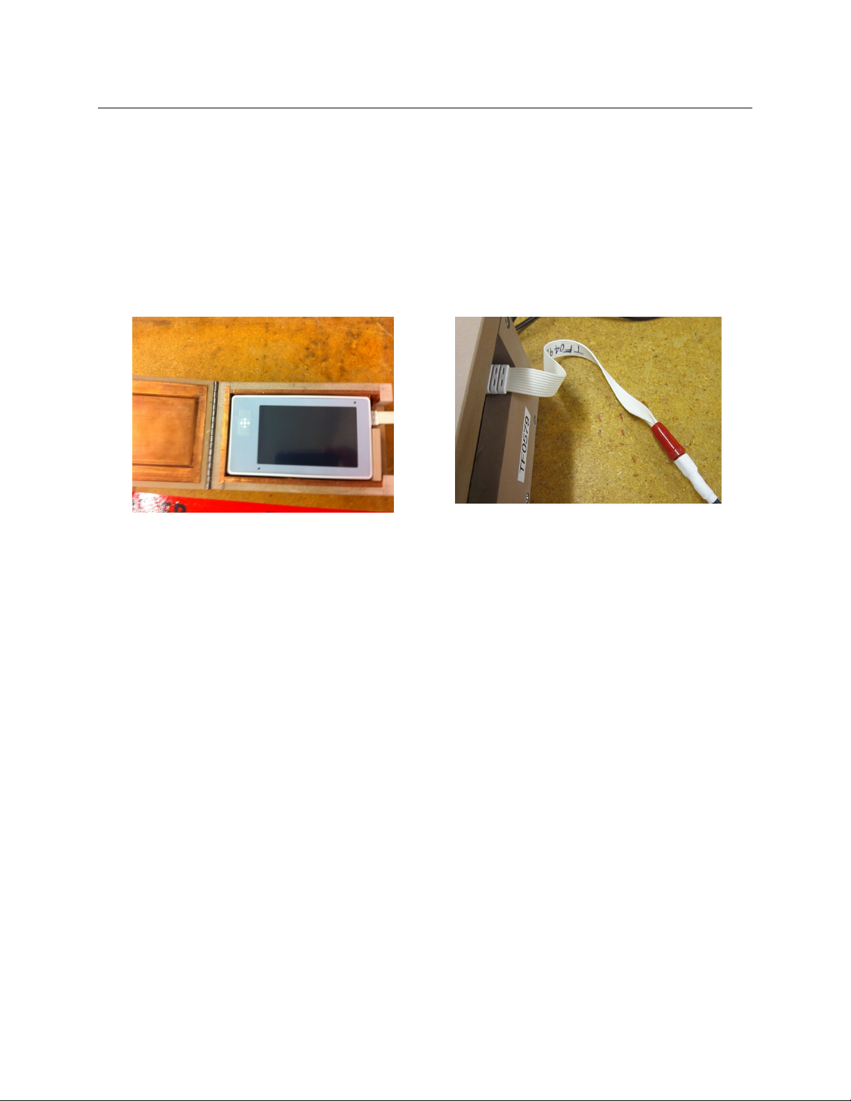
Test Process
• Place the appropriate Test Fixture Insert into Test Fixture (TF-0579) as follows. For Gen 1 device use TF-
0580 for the 3,4,5-wire SAM, or TF-0581 for the 10-wire SAM. For Gen 2 device use TF-0633 for the 3,5wire SAM, or the TF-0634 for the 10-wire SAM.
• Plug the patient cable end on the S4 Hi-Pot Test Fixture (TF-0619 for 10 Lead SAM) or (TF-0612 for 3/4/5
Lead SAM) into the patient input on the UUT, then insert the UUT into TF-0579 and close the fixture.
SECTION 4
• Connect the Red (positive) test lead of the DC Hi-Pot tester to the terminal on (TF-0619 For 10 Lead SAM
) or (TF-0612 For 3/4/5 Lead SAM)
• Connect the Black (negative) test lead of the DC Hi-Pot tester to the black terminal of TF-0579.
• Set the DC Hi-Pot tester to 5 KVDC and a pply power to the test setup by pressing the Test button.
• Verify the current draw remains less than 200uA for a minimum of 1 second. The display of t he Hi-Pot
tester will display a PASS result is the test limits are met or a FAIL result if test limits ar e no t met.
• Press the Reset button on the Hi-Pot Tester,
• If the S4 has the SpO2 option, remove TF-0579 from the black terminal, and connect TF-0643 to the black
terminal of the DC Hi-Pot Tester.
• Apply power to the test setup by pressing the Test button.
• Turn the DC Hi-Pot tester off, and wait 5 seconds.
• Remove the UUT from the fi xture.
42
Page 51

SECTION 4
Record a passing test result by checking the box on the test data record. If the test failed, write the
reason for failure underneath the safety testing heading on the test data record and do NOT check the
box.
Device Cleaning
Clean device per the instructions provided in the Maintenance & Cleaning section of the Service Manual prior to
packaging for storage/shipment.
43
Page 52

S4 Mobile Monitor Conformance Test Data Record
Unit Serial #:_______________________ Software Version:__________
Unit Part #:__________________________________________________
Indicate the step was performed successfully by checking the corresponding check box, and recording test
result.
IPX4 Vacuum Leak Testing
Unit Body Pass/Fail
Battery Door Pass/Fail
Verify Power Up / LED Operation
Lithium Ion Battery Pass/Fail
AA Battery Pass/Fail
Verify WiFi Connectivity Pass/Fail
Verify Version Information
Serial number Pass/Fail
Part Number Pass/Fail
Software Version Pass/Fail
Perform LCD Check Pass/Fail
Perform Touch Screen Calibration Pass/Fail
Perform Lead Failure Test Pass/Fail
Perform S4 / Surveyor Central ECG Performance Test Pass/Fail
Verify Waveform Display Quality
Verify HR @ 60 bpm +/- 3bpm __________ Pass/Fail
Verify HR @ 300 bpm +/- 3bpm __________ Pass/Fail
Verify Pace Spike @ 80 bpm Pass/Fail
Perform S4 / Surveyor Central SPO2 Performance Test N/A
Verify Operation with finger / Waveform Display Quality Pass/Fail
SECTION 4
44
Page 53

Verify 96% +/- 2% __________ Pass/Fail
Verify 70% +/- 2% __________ Pass/Fail
Verify “CHECK SENSOR” Message with Signal Removed Pass/Fail
Verify “NO SENSOR” Message with Cable Removed Pass/Fail
Perform Safety Testing
Hi-Pot Test Pass/Fail
SpO2 Option Hi-Pot Test Pass/Fail/not Installed
Device Cleaning Completed
Performed by: ______________________________ Date: _____/_____/_____
SECTION 4
45
Page 54

DEVICE SPECIFICATIONS
Continuous 12-lead signal acquisition and transmission with 10-wire
Continuous 7-lead signal acquisition and transmission with 5-wire cables
10-wire: I, II, III, aVR, aVL, aVF, V1, V2, V3, V4, V5 and V6
3-wire: I, II or III
Lead impedance check, ECG display, lead fail, battery notificatio n, multipurpose call; 10-wire
High definition, antiglare Colo r TFT-LCD with LED backlight and resistive
touch panel controls
Operating temperature: +10° to +40° C (+50° to +104° F)
Storage temperature: -40° to +70° C (-40° to +158° F)
Operating hu mid it y: 10% to 95% RH, non-condensing
Storage humidity: 10% to 95% RH, non-condensing
Operating & Storage: 62 kPa to 106 kPa
corresponds to an approx. altitude range of -380 m to 4000 m (-1250 ft to 13000 ft)
Cooling
Passive (no fan)
Weight
300g (10.6 oz) with rechargeable battery pack
IP classification
IPX4 – This device is protected against harmful effects of water splashed from
any direction per IEC 60529.
General
Instrument Type ECG digital mobile monitor
Dimensions 5.5” x 3.1” x 1.3” (139 x 79 x 33 mm)
SECTION 5
Input Channe ls
ECG Leads Transmitted
Device Classification Type CF, battery operated
Special Functions
Defibrillator Protection Complies with IEC 60601-2-25 (with 10-wire cable) and/or IEC 60601-2-27
Function Keys Control butt on; touchscreen menu navigation
Display type
Display size 4.3 inches (11 cm) diagonal; active area
Display resolution 480 x 800 pixels
LeadForm cable
5-wire: I, II, III, aVR, aVL, aVF, V
Environmental
Temperature
Humidity
Altitude
46
Page 55
Disposable Battery Type
Three (3) AA alkaline batteries
Disposable Battery Life
12 Hours
Rechargeable Battery Type
Rechargeable Lithium-Ion battery pack
Rechargeable Battery Run-Time
20 Hours
Battery Charging Time
8 Hours
12-lead ECG with specific Signal Acquisition Module (SAM10)
7-lead ECG with specific Signal Acquisition Module (SAM 5)
10-wire: I, II, III, aVR, aVL, aVF, V1, V2, V3, V4, V5, V6
3-wire: I, II, or III
Acquisition Rate:
40,000 samples/s. for pacemaker detection, 500 samples/s. for analysis
Resolution:
.117µV originally, reduced to 2.5 µV for processing and transmission
Dynamic Range
± 350mV
ECG Gain
½x, 1x, 2x
Trace Speed
slow, normal, fast
CMRR:
According to applicable standards (IEC 60601-2-25 and/or IEC 60601-2-27)
Pacemaker Spikes
Detect and report pacemaker spikes up to 2 ms duration with 1 samples precision
Max. Auxiliary Patient
Current:
Frequency Response:
0.05 to 150 Hz
Input Impedance:
>2.5 M Ω at 10 Hz
Electrodes:
Compatible with Ag/AgCl disposable electrodes
HR Report fro m the Central
Station
Less than one second. Heart rate is only available when the S4 is actively
communicating with the Central Station.
Minimum Q R S Amplitud e:
160µV
Recovery from
Defibrillation Discharge
Power Requirements & Batter y
ECG Specifications
ECG
SECTION 5
Simultaneous Leads
Available
5-wire: I, II, III, aVR, aVL, aVF, V
< 10 µA
Less than 5 seconds, compliant with IEC 60601-2-25 and/or IEC 60601-2-27.
47
Page 56

Technology
Mortara SpO2
Method
Absorption – Spectrophotometric (dual wavelength)
(Functional oxygen saturation of arterial hemoglobin)
Patient populations
Child (greater than 2 through 12 years of age)
Adult (greater than 21 years of age)
Parameters
% SpO2
Plethysmograph
Resolution
PR:
1 bpm
Range
PR:
30 – 240 bpm
Accuracy (RMS)
70% to 100% SpO2:
FingerClip type sensor: 2.1%
Disposable Wrap type sensor: 3.0%
Less than 70% SpO2:
Unspecified
PR:
±3 bpm
Update interval
1 second
Numeric values held < 30 seconds
Wavelength *
Infrared:
890 nm, nominal
Optical output power
Infrared:
0.5 mW – 3.0 mW
Wireless protocol
802.11g supported rates
6, 9, 12, 18, 24, 36, 48, 54 Mbps
802.11n supported rates
MCS0 through MCS7
6.5, 13, 19.5, 26, 39, 52, 58.5, 65 Mbps
Transmit Power
15 dBm
Configure WLAN APs maximum transmitting power to 15 dBm
SpO2 specifications
SpO2:
SpO2:
SECTION 5
Adolescent (greater than 12 through 21 years of age)
Pulse rate
1 % SpO2
30 – 100 %, calibrated range 70-100%
SoftTip type sensor: 1.3%
Red:
660 nm, nominal
Red:
0.5 mW – 4.5 mW
* This information may b e useful for clinicians performing photodynamic therapy.
Wireless Network Specifi cations
802.11 g/n 2.4GHz
Frequency Range 2400.96 MHz to 2482.56 MHz
48
Page 57

Channels
1 to 13 supported.
will cause short data gaps. Reduce the number of channel changes per day.
Wireless security protocols
WPA2-PSK-AES
Passphrase or H EX psk
WMM / QoS
Yes
Device uses class AC_VI (Video)
SSID Requirements
Dedicated SSID. Hidden SSID not supported.
Dedicated Monitoring VLAN is recommended.
IP address assignment
Static or DHCP
IP protocols and ports
UDP: one port per device, according to the system configuration (i.e. 20100,
ICMP and mDNS for management and service
Maximum devices per
Access Point
16
Data Rate (payload)
Outbound: up to 140 kbps (depending on configuration)
Inbound: < 16 kbps
Minimum RSSI / SNR
-75 dB in the coverage area
Minimum SNR
20 dB in the coverage area
SECTION 5
Need to configure used channels on devices prior to installation (default is 1, 6,
11)
If dynamic channel selection on WLAN infrastructure is enabled, channels change
WPA2-PSK-TKIP (supported but not recommended)
WPA-PSK-AES (supported but not recommended)
WPA-PSK-TKIP (supported but not recommended)
SSID can be up to 32 ASCII characters long, per 802.11.
SSID prioritization and minimum bandwidth configuration on WLAN
infrastructure is recommended.
Period Session Timeout or similar policies should be disabled or excluded in the
SSID dedicated to the S4: these policies might cause data gaps of a few seconds
whenever the AP terminates the session.
20101, 20102, etc…). Actual ports will be communicated upon definition of the
system configuration;
SSH
49
Page 58

SECTION 5
50
Page 59
TROUBLESHOOTING
Symptom
Possible Causes
Suggested Resolution
Replace the battery according to instructions in the
General Care & Maintenance chapter.
Symptom
Possible Causes
Suggested Resolution
Power cycle the S4 and try again. If problems persist,
Support.
Symptom
Possible Causes
Suggested Resolution
Check to make sure electrodes are still securely
techniques.
Power and Battery
SECTION 6
Internal system failure.
The S4 is not working and
display does not light up.
Battery Contacts
Battery will not hold charge.
Display and Touchscreen
The touchscreen is not
working properly.
The display is not working
properly.
Touchscreen failure.
Display failure.
Power cycle the S4 with fresh batteries and try again.
If problems persist, stop using the S4 and contact
Mortara Technical Support.
Remove the battery(s) and inspect the battery
contacts to ensure they are making a proper
connection.
Power cycle the S4 and try again. If problems persist,
stop using the S4 and contact Mortara Technical
Support.
stop using the S4 and contact Mortara Technical
ECG Trace
Excessive patient movement.
ECG signal is noisy.
Electrical noise from auxiliary
equipment.
Bad electrode contact.
Confirm electrode site preparation; confirm correct ECG
positioning, move electrodes if needed.
Isolate the patient from auxiliary equipment, if possible.
attached to the patient, and reattach if necessary.
Remember the importance of good skin preparation
51
Page 60

Symptom
Possible causes
Suggested remedies
Signal Quality
The physiological signal
Check patient status. Consider dark skin pigmentation, low
Intermittent
Circulation is being cutoff
Select an alternate measurement site for NIBP or SpO2.
Inaccurate values
Interfering substances in
Check the patient condition for carboxyhemoglobin,
Physiological conditions
Check the patient condition for cardiac arrest, hypotension,
Cannot obtain
The signal sensed by the
Refer the row further above for possible ways to improve
Excessive artifact on the
Refer the row below describing “’Artifact’ status message”.
No signal is being received
Refer to the row further below describing “Pleth waveform is a
Electromagnetic
Do not use the S4 with electrosurgery equipment.
Pulse oximetry (SpO2)
SECTION 6
Indicator is
yellow;SpO2
values continue to
be shown.
dropouts of pleth
waveform and
values
SpO
2
SpO2 reading
sensed by the SpO2
sensor is weak
at the SpO2 measurement
which is distal to a NIBP
cuff
the patient’s bloodstream
SpO2 sensor is so weak
that it is not recognized as
physiological
perfusion, venous pulsation, dysfunctional hemoglobins as
potential factors.
Remove nail polish from sensor site.
Confirm the fit of the sensor at the measurement site – not too
loose, nor too tight that circulation may be affected in the
extremity.
Try alternate measurement sites.
methemoglobin, intravascular dy es, or simil ar.
shock, severe vasoconstriction, severe anemia, hypothermia,
venous pulsations, ventral septal defects, extremes in
systemic vascular resistance, or similar.
signal strength.
sensor signal makes it
impossible to calculate
SpO
2
from the sensor
interference from ext ernal
equipment
52
square wave”
Check the immediate area of the S4 for other electronic
equipment. Increase the separation distance between them.
Consider discontinuing their use if not needed for patient
care.
Page 61

Symptom
Possible causes
Suggested remedies
“Artifact” status
Excessive patient
Advise patient to keep the measurement site still.
External light source
Redirect the external light source away from the
No signal is being received
Confirm the sensor has not been damaged. Replace if
Pleth waveform is
A physiological signal is
Confirm that the sensor is still applied to the patient.
Sensor and/or extension
Replace sensor and/or extension cable
Symptom
Possible Causes
Suggested Resolution
1. "No ECG Monitoring" alarm and no
screen.
Check LAN IPv4 network settings;
to correct issues.
SECTION 6
message
movement
produces interference at
the sensor
from the sensor
a square wave
not being detected by the
sensor
cable is damaged
Network Transmissi on
Select an alternate measurement site less prone to
movement.
measurement site.
Cover the sensor site.
necessary.
Confirm the sensor and/or extension cable being used are
one of those recommended in this manual for use with the S4.
Confirm connections of sensor and extension cable to the S4.
1. "No ECG Monitoring" alarm.
2. “Trying to connect to Central" error
message displayed.
3. X symbol on WiFi signal indicator.
4. Fast blinking blue LED.
5. "AP MAC: Not-Associated" in the WiFi
diagnostic screen.
6. Invalid IP address if configured for
DHCP.
7. Inability to ping in WiFi diagnostic
screen.
traces on the Central Station.
2. “Trying to connect to Central" error
message displayed.
3. Normal symbol on WiFi signal
indicator.
4. Slow blinking blue LED.
5. Network info correctly populated in
WiFi diagnostic screen.
6. Invalid IP address if configured for
DHCP.
7. Inability to ping in WiFi diagnostic
Incorrect WLAN configuration (e.g.,
SSID, Security protocol, Passkey,
Passkey type).
WLAN infrastructure issues (e.g.
device placed on black list).
Incorrect LAN configuration (Method,
IP, Subnet, Gateway).
LAN infrastructure issues (e.g. DHCP
server is not providing an IP address).
Check WiFi network settings; contact
your IT Network Administrator to
correct issues.
Check WiFi network settings; contact
your IT Network Administrator to
correct issues.
Check LAN network settings; contact
your IT Network Administrator to
correct issues.
contact your IT Network Administrator
53
Page 62

Symptom
Possible Causes
Suggested Resolution
Any of the following:
screen.
SECTION 6
1. "No ECG Monitoring"
alarm and no traces on
the Central Station.
2. “Trying to connect
to Central" error
message displayed.
3. Normal symbol on WiFi
signal indicator.
4. Slow blinking blue LED.
5. Network info correctly
populated in WiFi
diagnostic screen.
6. Valid IP address if
configured for DHCP.
7. Ping successful for
some IP addresses in
WiFi diagnostic screen.
1. Intermittent traces on
Central Station,
intermittent "No ECG
Monitoring" alarm.
2. Intermittent "Trying to
connect to Central" error
in top bar.
3. X or low signal symbol on
WiFi signal indicator.
4. Intermittent fast blinking
blue LED.
5. Intermittent "AP MAC:
Not-Associated" in
WiFi diagnostic screen,
low signal, high noise,
low quality indexes.
6. Intermitte nt Valid IP
address if configured for
DHCP.
7. Inconsistent Ping results
in WiFi diagnostic
Incorrect Host/Central stations
configuration.
Mismatch between Unit/Bed ID
and Base Port configuration on
S4 and Central stations.
Surveyor Central Station is not
running.
Security router not correctly
configured.
LAN infrastructure issues (i.e.
ports not routed to Security
router, disconnected cables).
Poor WLAN network coverage. Check IT Network Administrator to correct issues.
Check S4 Host settings and/or Central Station
configuration.
Check S4 Host settings and/or Central Station
configuration.
Check Central Station configuration.
Check Security router configuration and status.
Check LAN IPv4 network settings; contact your IT
Network Administrator to correct issues.
54
Page 63

Message
Possible Causes
Suggested Resolution
The configured slot is
device.
Ensure that the configuration passcode entered as well
as the confirmation passcode values match.
ECG Frontend
service.
Unable to open ECG
persists contact service.
Error Messages
SECTION 6
Trying to connect to
Central...
already used by another
Unlock failed. Incorrect passcode used. Enter the correct passcode.
Enter New Passcode. Mismatch of passcodes entered.
calibration failed, restart
the device. If the
problem persists contact
Frontend, restart the
device. If the problem
Not able to connect to the Surveyor
Central Station.
Selected slot for the Surveyor Central
Station is currently in use.
Calibration of the ECG frontend failed.
Interface to the ECG frontend failed.
Check network settings and access of WiFi network.
Also refer to the Network Transmission items above.
Select a different slot for this monitor.
Power the system on and off. Contact Mortara if the
problem persists.
Power the system on and off. Contact Mortara if the
problem persists.
55
Page 64
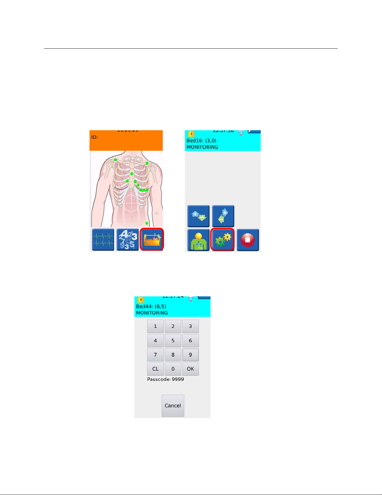
SECTION 6
WiFi Diagnostics
The WiFi Diagnostics screen is for assessing the network interface including confirming network set ti ng s,
determining signal strength and using a PING tool to test the connection to the Central Station. The IP address of
the Central Station defined in the host settings is automatically populated. Another address may be manually
entered to test alternative IP address as necessary.
To access the WiFi diagnostic screen, press the toolkit icon from the main screen, then press the gears icon.
The following pass code screen will appear to limit access to certain device functions.
The S4 is factory shipped with passcode 7865. Refer to your facility’s administrator for ad ditional information.
Pass code Entry Screen
56
Page 65
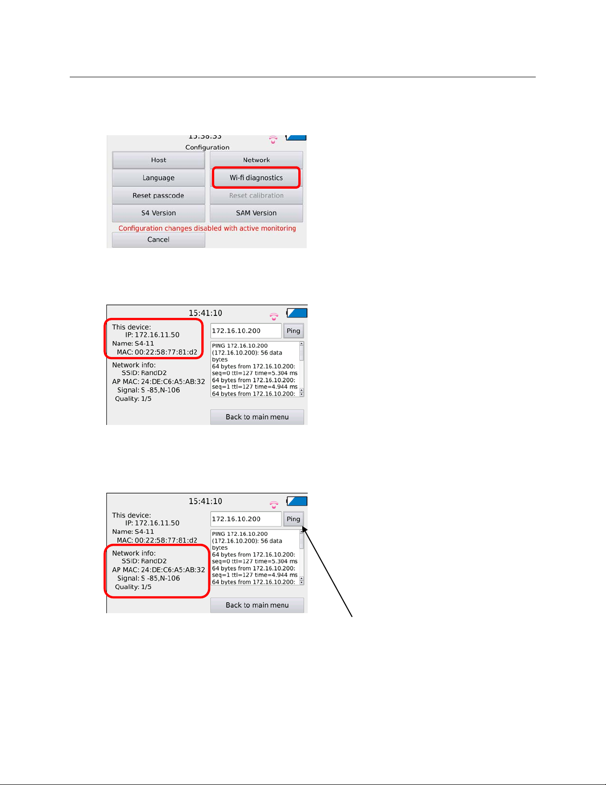
SECTION 6
Once the pass code is correctly entered, the following configuration menu appears, select the WiFi diagnostics
option.
The WiFi diagnostic screen provides information regarding the IP address, device name, and the MAC address of
the S4 monitor.
The diagnostic screen also provides information regarding the SSID of the network it is configured to connect to, the
MAC address of the access point it is currently connected to, the signal strength (S), the noise floor (N) , and the
overall quality of the connection to the access point (number of bars).
The diagnos tic screen is also equipped with a PING tool to test the connection to the Centr a l Sta tion. The IP address
of the Central Station defined in the ho st settings is automatically populate d. Another address may be manually
entered to test alternative IP address as necessary.
57
 Loading...