

Page 1

ELI 25O
12-LEAD RESTING ELECTROCARDIOGRAPH
REF 9515-163-50-ENG Rev F1
Manufactured by Mortara Instrument, Inc. Milwaukee, Wisconsin U.S.A.
CAUTION: Federal law restricts this device for sale to or on the order of a physician.
USER MANUAL
Page 2

Copyright© 2003
by Mortara Instrument, Inc.
7865 N. 86th Street
Milwaukee, Wisconsin 53224
This document contains confidential information that belongs to Mortara Instrument, Inc. No part of this document
may be transmitted, reproduced, used, or disclosed outside of the receiving organization without the express written
consent of Mortara Instrument, Inc. Mortara is a registered trademark of Mortara Instrument, Inc. ELI 250 is a
trademark of Mortara Instrument, Inc.
Page 3

Sales Support/
Supplies & Accessories
Mortara Instrument, Inc.
7865 North 86th Street
Milwaukee, WI 53224
Tel: 414.354.1600
Fax: 414.354.4760
E-mail: [email protected]
Mortara Instrument GmbH
(Germany)
Kaninenberghöhe 50
45136 Essen
Tel: +49.201.268311
Fax: +49.201.268313
Mortara Instrument B.V.
(The Netherlands)
H. Dunantplein 6
3731 CL De Bilt
Postbus 131
3720 AC Bilthoven
Tel: +31.30.2205050
Fax: +31.30.2201531
Headquarters
Mortara Instrument, Inc.
7865 North 86th Street
Milwaukee, WI 53224
Tel: 414.354.1600
Tel: 800.231.7437
Fax: 414.354.4760
Internet: http://www.mortara.com
Europe Economic
Community Representative
Mortara Rangoni Europe, Srl
(European Headquarters, Italy)
Via Cimarosa
40033 Casalecchio di Reno (BO)
Tel: +39.051.298.7811
Fax: +39.051.613.3582
Service/Technical
Support Group
Mortara Instrument, Inc.
7865 North 86th Street
Milwaukee, WI 53224
Tel: 414.354.1600
Service: 888.MORTARA
24 Hour Technical Support
Same Day Shipment of Replacement Parts
Biomedical Training Classes
Extended Warranties/Service Contracts
TECHNICAL SUPPORT AND SERVICE
i
Page 4

NOTICES
Manufacturer’s Responsibility
Mortara Instrument, Inc., is responsible for the effects on safety and performance only if:
• Assembly operations, extensions, readjustments, modifications or repairs are carried out only by persons
authorized by Mortara Instrument, Inc.
•The device (ELI 250) is used in accordance with the instructions for use.
Responsibility of the Customer
The user of this product is responsible for ensuring the implementation of a satisfactory maintenance
schedule. Failure to do so may cause undue failure and possible health hazards.
Equipment Identification
Mortara Instrument, Inc. equipment is identified by a serial and reference number on the back of the
device. Care should be taken so that these numbers are not defaced.
Copyright and Trademark Notices
This document contains information that is protected by copyright. All rights are reserved. No part of this
document may be photocopied, reproduced or translated to another language without prior written consent
of Mortara Instrument, Inc.
Other Important Information
The information in this document is subject to change without notice.
Mortara Instrument, Inc. makes no warranty of any kind with regard to this material including, but not limited
to, implied warranties of merchantability and fitness for a particular purpose. Mortara Instrument, Inc. assumes
no responsibility for any errors or omissions that may appear in this document. Mortara Instrument Inc. makes
no commitment to update or to keep current the information contained in this document.
ii
Page 5

Your Mortara Warranty
MORTARA INSTRUMENT, INC. (hereinafter referred to as “Mortara”) hereby warrants that Mortara
products (hereinafter referred to as “Products”) shall be free from defects in material and workmanship under
normal use, service and maintenance for the warranty period of such Product from Mortara or an authorized
distributor or representative of Mortara. Normal use, service and maintenance means operation and
maintenance in accordance with appropriate instructions and/or information guides. This Warranty does not
apply to damage to the Products caused by any or all of the following circumstances or conditions:
a) Freight damage;
b) Parts and/or accessories of the Products not obtained from or approved by Mortara;
c) Misapplication, misuse, abuse and failure to follow the Product instruction sheets and/or information guides;
d) Accident, a disaster affecting the Products;
e) Alterations or modifications to the Products not authorized by Mortara;
f) Other events outside of Mortara’s reasonable control or not arising under normal operating conditions.
THE REMEDY UNDER THIS WARRANTY IS LIMITED TO THE REPAIR OR REPLACEMENT
WITHOUT CHARGE FOR LABOR OR MATERIALS, OR ANY PRODUCTS FOUND UPON
EXAMINATION BY MORTARA TO HAVE BEEN DEFECTIVE. This remedy shall be conditioned upon
receipt of notice by Mortara of any alleged defects promptly after discovery thereof within the warranty period.
Mortara’s obligations under the foregoing warranty will further be conditioned upon the assumption by the
purchaser of the Products (i) of all carrier charges with respect to any Products returned to Mortara’s principal
place or any other place as specifically designated by Mortara or an authorized distributor or representative of
Mortara, and (ii) all risk of loss in transit. It is expressly agreed that the liability of Mortara is limited and that
Mortara does not function as an insurer. A purchaser of a Product, by its acceptance and purchase thereof,
acknowledges and agrees that Mortara is not liable for loss, harm or damage due directly or indirectly to an
occurrence or consequence therefrom relating to the Products. If Mortara should be found liable to anyone
under any theory (except the expressed warranty set forth herein) for loss, harm or damage, the liability of
Mortara shall be limited to the lesser of the actual loss, harm or damage, or the original purchase price of the
Product when sold.
EXCLUDED FROM THE LIMITED WARRANTY SET FORTH ABOVE ARE CONSUMABLE ITEMS
SUCH AS PAPER, BATTERIES, ELECTRODES, PATIENT CABLES, LEAD WIRES AND MAGNETIC
STORAGE MEDIUMS.
EXCEPT AS SET FORTH HEREIN WITH RESPECT TO REIMBURSEMENT OF LABOR CHARGES,
A PURCHASER’S SOLE EXCLUSIVE REMEDY AGAINST MORTARA FOR CLAIMS RELATING TO
THE PRODUCTS FOR ANY AND ALL LOSSES AND DAMAGES RESULTING FROM ANY CAUSE
SHALL BE THE REPAIR OR REPLACEMENT OF DEFECTIVE PRODUCTS TO THE EXTENT THAT
THE DEFECT IS NOTICED AND MORTARA IS NOTIFIED WITHIN THE WARRANTY PERIOD. IN
NO EVENT, INCLUDING THE CLAIM FOR NEGLIGENCE, SHALL MORTARA BE LIABLE FOR
INCIDENTAL, SPECIAL OR CONSEQUENTIAL DAMAGES, OR FOR ANY OTHER LOSS, DAMAGE
OR EXPENSE OF ANY KIND, INCLUDING LOSS OF PROFITS, WHETHER UNDER TORT,
NEGLIGENCE OR STRICT LIABILITY THEORIES OF LAW,OR OTHERWISE.THIS WARRANTY IS
EXPRESSLY IN LIEU OF ANY OTHER WARRANTIES, EXPRESS OR IMPLIED, INCLUDING, BUT
NOT LIMITED TO THE IMPLIED WARRANTY OF MERCHANT ABILITY AND THE WARRANTY
OF FITNESS FOR A PARTICULAR PURPOSE.
WARRANTY INFORMATION
iii
Page 6
USER SAFETY INFORMATION
Means there is the possibility of personal injury to you or others.
Means there is the possibility of damage to the equipment.
Provides information to further assist in the use of the device.
Federal law restricts this device for sale to or on the order of a physician.
• Device (electrocardiograph, Class I) captures and presents data reflecting a patient’s physiological condition
that when reviewed by a trained physician or clinician can be useful in determining a diagnosis. However,
the data should not be used as a sole means for determining a patient’s diagnosis.
•To ensure that electrical safety is maintained during operation from AC (~) power, the device must be
plugged into a Hospital Grade outlet.
•To maintain designed operator and patient safety, peripheral equipment and accessories used that can come
in direct patient contact, must be in compliance with UL 2601-1, IEC 601-1 and IEC 601-2-25.
• Patient cables intended for use with the ELI 250 include series resistance (10 Kohm minimum) in each lead
for defibrillation protection. Patient cables should be checked for cracks or breakage prior to use.
• Conductive parts of the patient cable, electrodes and associated connections of Type CF applied parts,
including the neutral conductor of the patient cable and electrode should not come into contact with
other conductive parts, including earth ground.
•To maintain designed operator and patient safety, only use parts and accessories supplied with the device
and available through Mortara Instrument, Inc.
• ECG electrodes could cause skin irritation and should be examined for signs of irritation or inflammation.
•To prevent possible infection, single use components (e.g., electrodes) should be limited to one-time use only.
•To avoid the possibility of serious injury or death during patient defibrillation, do not come into contact with
device or patient cables. Additionally, proper placement of defibrillator paddles in relation to the electrodes
is required to minimize harm to the patient.
•To ensure the safety of both the patient and the device, 1.5 meters (5 feet) of open area should surround
the patient.
•A possible explosion hazard exists; do not use the device in the presence of flammable anesthetics.
iv
Warning
Warning(s)
Caution
Note
Page 7

• Before attempting to use the device for clinical applications the operator must read and understand the
contents of the manual and any documents accompanying the device.
•Where the integrity of external protective earth conductor arrangement is in doubt, the ELI 250 shall be
operated from its internal electrical power source.
• All signal input and output (I/O) connectors are intended for connection of only devices complying with
IEC 60601-1, or other IEC standards (e.g. IEC 60950), as appropriate to the device. Connecting additional
devices to the ELI 250 may increase chassis and/or patient leakage currents. To maintain operator and
patient safety, consideration should be given to the requirements of IEC 60601-1-1, and leakage currents
should be measured to confirm no electric shock hazard exists.
•To maintain immunity to potential interfering electromagnetic signals, shielded cabling must be used when
connecting the ELI 250 to a network.
•To maintain operator and patient safety, equipment connected to the same network as the ELI 250 must
meet the requirements of IEC 60950 or IEC 60601-1.
•To prevent electric shock due to unequal ground potentials that may exist between points of a distributed
network system, or fault conditions in external network connected equipment, network cable shielding must
be connected to protective earth ground appropriate to the area where the ELI 250 is used.
•The ELI 250 has not been designed for use with high-frequency (HF) surgical equipment and does not
provide a protective means against hazards to the patient.
•The quality of the signal produced by the electrocardiograph may be adversely affected by the use of other
medical equipment, including but not limited to defibrillators and ultrasound machines.
•To prevent possible damage to the keypad, do not use sharp or hard objects to depress keys, only
use fingertips.
• Do not attempt to clean the device or patient cables by submersing into a liquid, autoclaving, or steam
cleaning as this may damage equipment or reduce its usable life. Wipe the exterior surfaces with a warm
water and mild detergent solution and then dry with a clean cloth.
• No user serviceable parts inside. Dangerous voltages present when Mains is applied. Screw removal by
qualified service personnel only.
•The rechargeable internal battery is a sealed lead acid type and it is totally maintenance free. If the battery
appears to become defective, refer to Mortara Instrument Service Department.
• Do not pull or stretch patient cables as this could result in mechanical and/or electrical failures. Patient
cables should be stored after forming them into a loose loop.
• Do not connect telephone cable to LAN connector.
User Safety Information (Continued)
v
Caution(s)
Page 8

User Safety Information (Continued)
• Excessive patient movement could interfere with the operation of the device.
• Proper patient preparation is important to proper application of ECG electrodes and operation of the device.
•There is no known safety hazard if other equipment, such as pacemakers or other stimulators, are used
simultaneously with the ELI 250; however, disturbance to the signal may occur.
• If the ECG amplifier input is out of normal operating range, the display will indicate a lead fail for the
lead(s) where this condition is present and if the signal is being printed, the respective lead(s) will print
out as a square wave.
•As defined by IEC 60601-1 and IEC 60601-2-25, the device is classified as follows:
• Class I equipment or internally powered
•Type CF applied parts
• Ordinary equipment
• Not suitable for use in the presence of flammable anesthetics
• Continuous operation
NOTE: From a safety perspective, per IEC 60601-1 and derivative standards / norms, this unit
is declared to be “Class I” and uses a three-prong inlet to ensure an earth connection is made
along with mains. The ground terminal on the mains inlet is the only protective earth point in
the unit. Exposed metal accessible during normal operation is double insulated from mains.
Internal connections to earth ground are functional earth.
•The ELI 250 will automatically turn off (blank screen) if the batteries have been severely discharged and
the AC mains is disconnected from the unit.
• After operating the ELI 250 using battery power, always reconnect the power cord. This ensures that the
batteries will be automatically recharged for the next time you use the ELI 250. A light will illuminate,
next to the on/off switch, indicating that the unit is charging. This light will turn off when the battery is
fully charged.
•The ELI 250 is a UL Classified Device:
WITH RESPECT TO ELECTRIC SHOCK,
FIRE AND MECHANICAL HAZARDS ONLY IN ACCORDANCE
WITH UL2601-1, IEC60601-1, CAN/CSA CC22.2 No. 601.1,
AND IEC60601-2-25
vi
Notes
5P35
Page 9
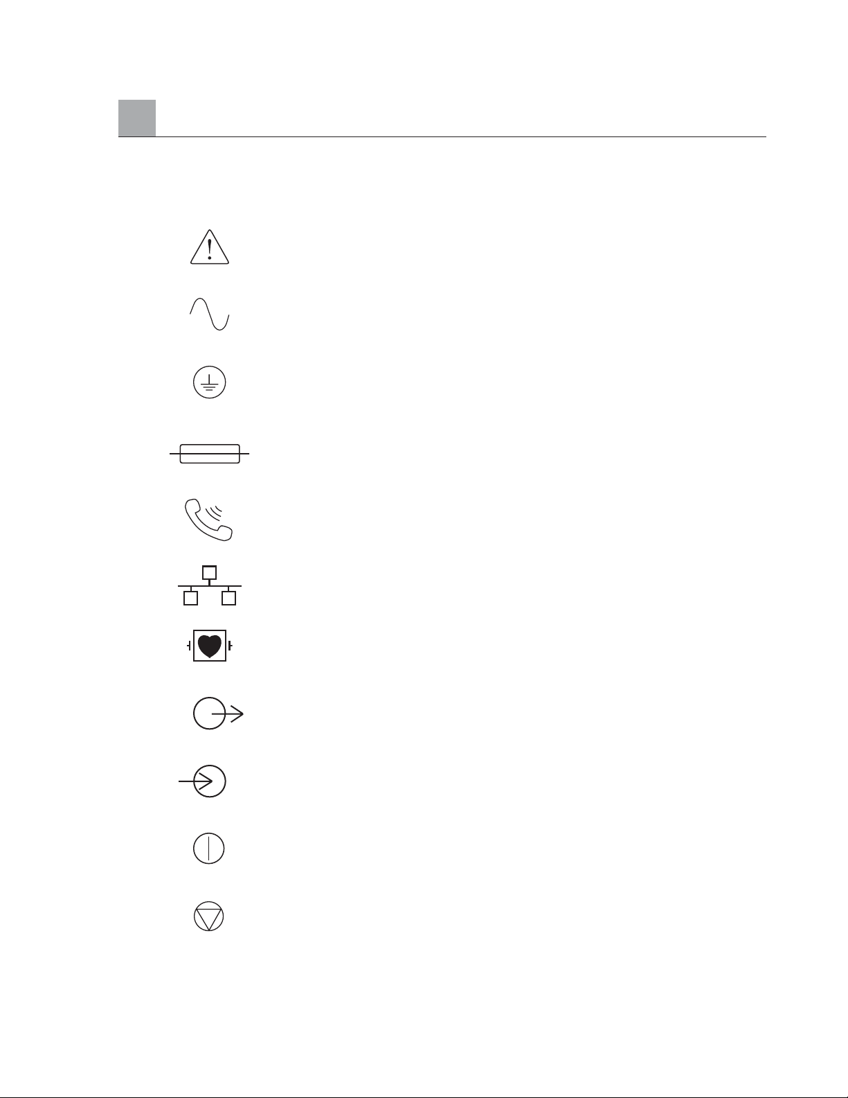
Symbol Delineation
Attention, consult accompanying documents
Alternating current
Protective earth (ground)
Fuse
Telephone line (modem)
Network (LAN)
Defibrillator-proof type CF applied part
Output/Transmit
Input
ON/OFF (power)
Stop (of action)
EQUIPMENT SYMBOLS AND MARKINGS
vii
Page 10
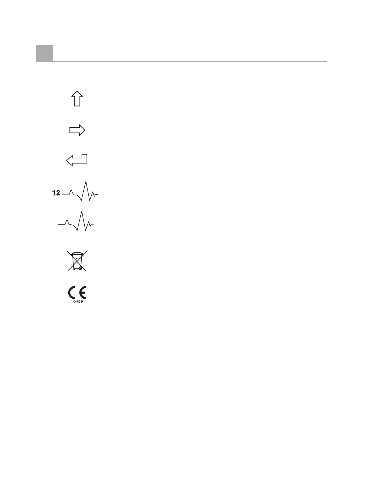
Equipment Symbols and Markings (Continued)
Shift key (to enter upper case text)
Space key
Enter key (accept data/return)
Initiate printing of 12-Lead ECG
Initiate printing of continuous rhythm strip
Do not dispose as unsorted municipal waste. Per EC
Directive 2002/96, requires separate handling for waste
disposal according to national requirements
Indicates compliance to applicable EEC directives
viii
Page 11

Electromagnetic compatibility with surrounding devices should be assessed when using the system.
An electronic device can either generate or receive electromagnetic interference. Testing for
electromagnetic compatibility (EMC) has been performed on the ELI 250 cardiograph according to the
international standard for EMC for medical devices (IEC 60601-1-2). This IEC standard has been adopted
in Europe as the European Norm (EN 60601-1-2).
The system should not be used adjacent to, or stacked on top of other equipment. If the system must be used
adjacent to or stacked on top of other equipment, verify that the system operates in an acceptable manner in the
configuration in which it will be used.
Fixed, portable, and mobile radio frequency communications equipment can affect the performance of
medical equipment. See Table X-4 for recommended separation distances between the radio equipment
and the system.
The use of accessories and cables other than those specified below, may result in increased emissions or
decreased immunity of the system.
9293-032-50 ELI 250 Patient cable, 12 channel, 10 leadwires banana plug - AHA
9293-032-51 ELI 250 Patient cable, 12 channel, 10 leadwires banana plug - IEC
9293-033-50 ELI 250 Patient cable, 12 channel, 10 leadwires snap - AHA
9293-033-51 ELI 250 Patient cable, 12 channel, 10 leadwires snap - IEC COLORS
9281-002-50 Banana plug to snap leadwire, 4mm, set of 10
3181-008 Power cord, hospital grade, 8' US
3181-002 Power cord, hospital grade, 8' INTERNATIONAL
ELECTROMAGNETIC COMPATIBILITY (EMC)
ix
Page 12
ELECTROMAGNETIC COMPATIBILITY (EMC) (Continued)
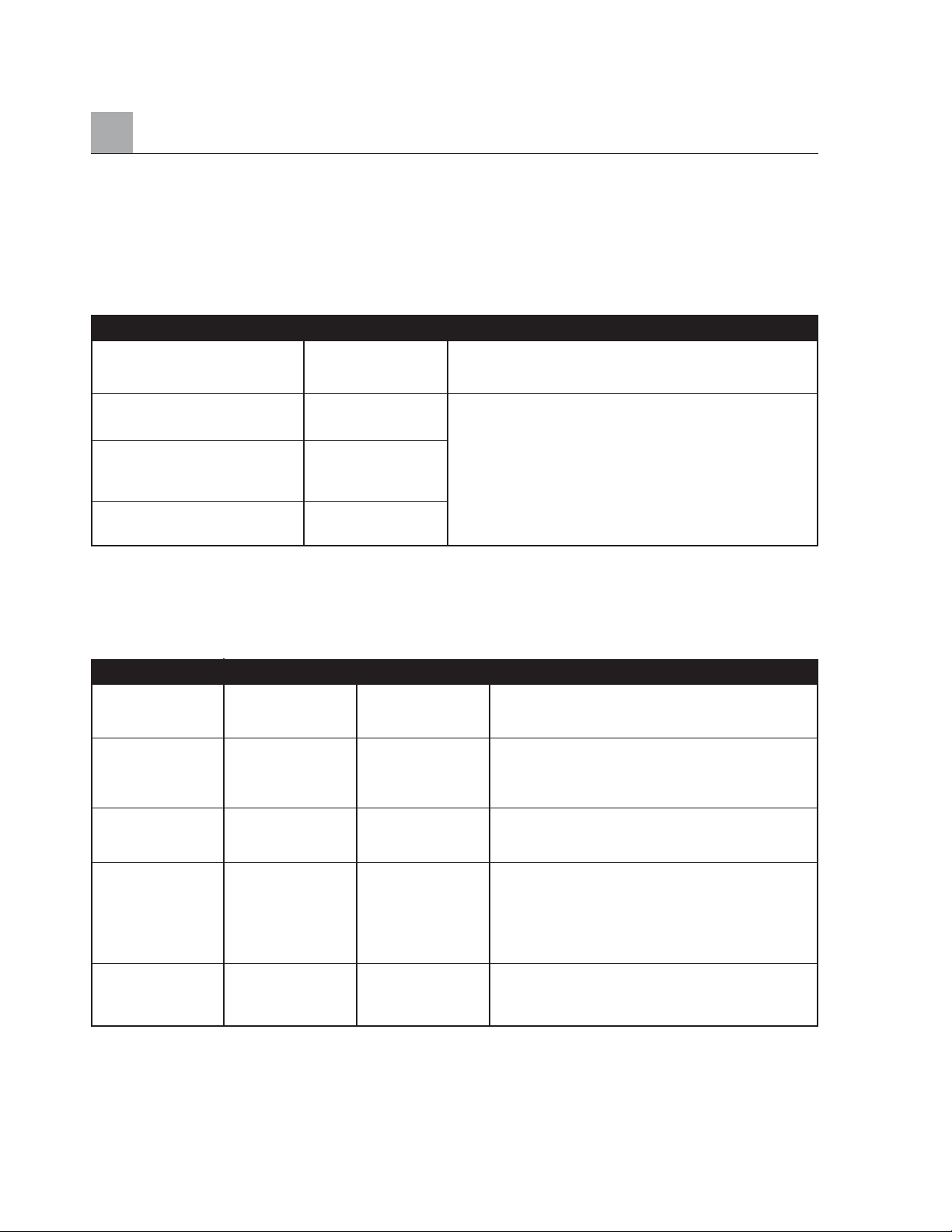
Table X-1 Guidance and Manufacturer’s Declaration: Electromagnetic Emissions
The system is intended for use in the electromagnetic environment specified in the table below. The
customer or the user of the system should assure that it is used in such an environment.
Table X-2 Guidance and Manufacturer’s Declaration: Electromagnetic Immunity
The system is intended for use in the electromagnetic environment specified below. The customer or the user
of the system should assure that it is used in such an environment.
NOTE: UT is the a.c. mains voltage prior to application of the test level.
x
Emissions Test Compliance Compliance Level Electromagnetic Environment: Guidance
Electrostatic +/- 6 kV contact +/- 6 kV contact Floors should be wood, concrete, or ceramic tile.
Discharge (ESD) +/- 8 kV air +/- 8 kV air If floors are covered with synthetic material, the
IEC 61000-4-2 relative humidity should be at least 30%.
Electrical Fast +/- 2 kV for +/- 2 kV for Mains power quality should be that of a typical
transient/burst power supply line power supply line commercial or hospital environment.
IEC 61000-4-4 +/- 1 kV for +/- 1 kV for
input/output lines input/output lines
Surge +/- 1 kV differential +/- 1 kV differential Mains power quality should be that of a typical
IEC 61000-4-5 mode +/- 2 kV mode +/- 2 kV commercial or hospital environment.
common mode common mode
Voltage dips, short <5% UT <5% UT Mains power quality should be that of a typical
interruptions and (>95% dip in UT) (>95% dip in UT) commercial or hospital environment. If the user of
voltage variations for 0.5 cycle for 0.5 cycle the system requires continued operation during
on power supply 40% UT 40% UT power mains interruptions, it is recommended that
input lines (60% dip in UT) (60% dip in UT) the system be powered from an uninterruptible
IEC 61000-4-11 for 5 cycles for 5 cycles power supply or a battery.
Power frequency 3 A/m 3 A/m Power frequency magnetic fields should be at levels
(50./60 Hz) characteristic of a typical location in a typical
magnetic field commercial or hospital environment.
Emissions Test Compliance Electromagnetic Environment: Guidance
RF Emissions CISPR 11 Group 1 The system uses RF energy only for its internal function.
Therefore, its RF emissions are very low and not likely to
cause any interference in nearby electronic equipment.
RF Emissions CISPR 11 Class A The system is suitable for use in all establishments
other than domestic and those directly connected to the
public low-voltage power supply network that supplies
Harmonic Emissions Complies buildings used for domestic purposes.
IEC 61000-3-2
Voltage fluctuations/flicker Complies
emissions IEC 61000-3-3
Page 13
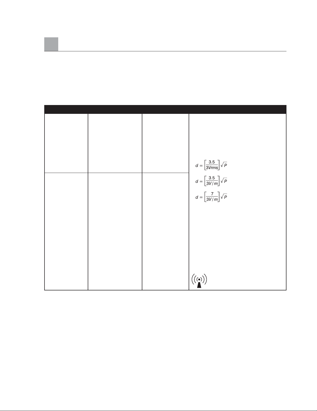
Table X-3 Guidance and Manufacturer’s Declaration: Electromagnetic Immunity
The system is intended for use in the electromagnetic environment specified below. The customer or the user
of the system should assure that they are used in such an environment.
a. Field strengths from fixed transmitters, such as base stations for radio (cellular/cordless) telephones and land mobile radios, amateur
radios,AM and FM radio broadcast and TV broadcast cannot be predicted theoretically with accuracy. To assess the electromagnetic
environment due to fixed RF transmitters, an electromagnetic site survey should be considered. If the measured field strength in the
location in which the system is used exceeds the applicable RF compliance level above, the system should be observed to verify normal
operation. If abnormal performance is observed, additional measures may be necessary, such as reorienting or relocating the system.
b. Over the frequency range 150 kHz to 80 MHz, field strengths should be less than [3] V/m.
ELECTROMAGNETIC COMPATIBILITY (EMC) (Continued)
xi
Emissions Test IEC 60601 Test Level Compliance Level Electromagnetic Environment: Guidance
Conducted RF 3 Vrms 150 kHz 3 Vrms 150 kHz Portable and mobile RF communications
IEC 61000-4-6 to 80 MHz to 80 MHz equipment should be used no closer to any
part of the system, including cables, than
the recommended separation distance
calculated from the equation applicable to
the frequency of the transmitter.
Recommended separation distance
Radiated RF 3 Vrms 80 MHz 3 Vrms 80 MHz
IEC 61000-4-3 to 2.5 GHz to 2.5 GHz
80 MHz to 800 MHz
80 MHz to 800 MHz
Where P is the maximum output power
rating of the transmitter in watts (W)
according to the transmitter manufacturer
and d is the recommended separation
distance in meters (m).
Field strengths from fixed RF transmitters,
as determined by an electromagnetic site
survey
a
, should be less than the compliance
level in each frequency range
b
.
Interference may occur in the vicinity of
equipment marked with the following symbol:
Page 14
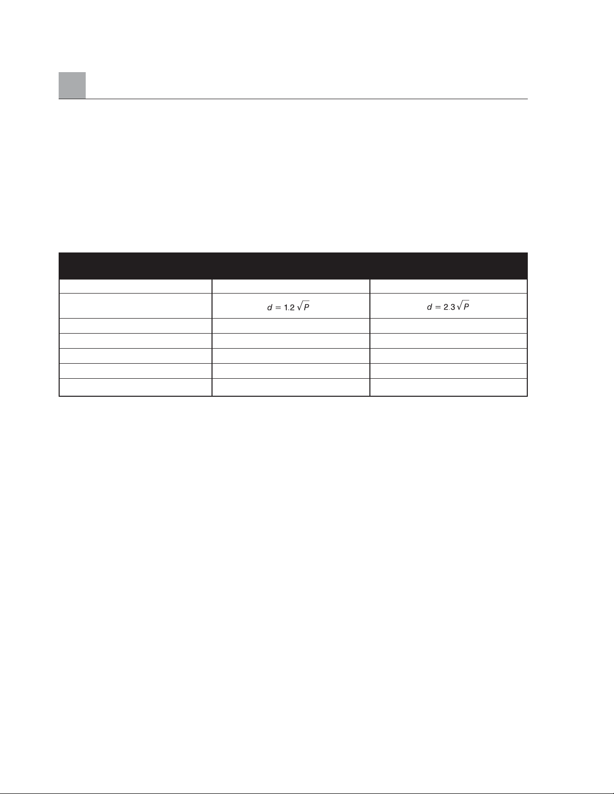
ELECTROMAGNETIC COMPATIBILITY (EMC) (Continued)
Table X-4 Recommended Separation Distances Between Portable and Mobile RF
Communications Equipment and the ELI 250 cardiograph.
The system is intended for use in the electromagnetic environment in which radiated RF disturbances
are controlled. The customer or the user of the system can help to prevent electromagnetic interference
by maintaining a minimum distance between portable and mobile RF communications equipment
(transmitters) and the system as recommended below, according to the maximum output power of the
communications equipment.
For transmitters rated at a maximum output power not listed above, the recommended separation distance d
in meters (m) can be estimated using the equation applicable to the frequency of the transmitter, where P is
the maximum output power rating of the transmitter in watts (W) according to the transmitter manufacturer.
NOTE 1: At 800 MHz, the separation distance for the higher frequency range applies.
NOTE 2: These guidelines may not apply in all situations. Electromagnetic propagation is
affected by the absorption and reflection from structures, objects, and people.
xii
Rated Maximum Output Separation Distance According to Frequency of Transmitter (m)
Power of Transmitter W
150 KHz to 800 MHz 800 MHz to 2.5 GHz
0.01 0.1 m 0.2 m
0.1 0.4 m 0.7 m
1 1.2 m 2.3 m
10 4.0 m 7.0 m
100 12.0 m 23.0 m
Page 15

INTRODUCTION SECTION 1
Manual Purpose . . . . . . . . . . . . . . . . . . . . . . . . . . . . . . . . . . . . . . . . . . . . . . . . . . . . . . . . . . . . . . . . . . . . . . . . . . . . . . . . . 1-1
Audience & Conventions . . . . . . . . . . . . . . . . . . . . . . . . . . . . . . . . . . . . . . . . . . . . . . . . . . . . . . . . . . . . . . . . . . . . . . . . . 1-1
Chapter Purpose . . . . . . . . . . . . . . . . . . . . . . . . . . . . . . . . . . . . . . . . . . . . . . . . . . . . . . . . . . . . . . . . . . . . . . . . . . . . . . . . 1-1
System Description . . . . . . . . . . . . . . . . . . . . . . . . . . . . . . . . . . . . . . . . . . . . . . . . . . . . . . . . . . . . . . . . . . . . . . . . . . . . . . 1-2
Figure 1-1, System Illustration . . . . . . . . . . . . . . . . . . . . . . . . . . . . . . . . . . . . . . . . . . . . . . . . . . . . . . . . . . . . . . . . . . . . . 1-2
System Layout . . . . . . . . . . . . . . . . . . . . . . . . . . . . . . . . . . . . . . . . . . . . . . . . . . . . . . . . . . . . . . . . . . . . . . . . . . . . . . . . . . 1-3
Figure 1-2, ELI 250 Left Side . . . . . . . . . . . . . . . . . . . . . . . . . . . . . . . . . . . . . . . . . . . . . . . . . . . . . . . . . . . . . . . . . . . . . 1-3
Figure 1-3, ELI 250 Rear . . . . . . . . . . . . . . . . . . . . . . . . . . . . . . . . . . . . . . . . . . . . . . . . . . . . . . . . . . . . . . . . . . . . . . . . . 1-3
Figure 1-4, ELI 250 Base . . . . . . . . . . . . . . . . . . . . . . . . . . . . . . . . . . . . . . . . . . . . . . . . . . . . . . . . . . . . . . . . . . . . . . . . . 1-4
Figure 1-5, ELI 250 Display and Keyboard . . . . . . . . . . . . . . . . . . . . . . . . . . . . . . . . . . . . . . . . . . . . . . . . . . . . . . . . . 1-5
Automatic Feature Keys . . . . . . . . . . . . . . . . . . . . . . . . . . . . . . . . . . . . . . . . . . . . . . . . . . . . . . . . . . . . . . . . . . . . . . . . . . 1-5
ELI 250 Specifications . . . . . . . . . . . . . . . . . . . . . . . . . . . . . . . . . . . . . . . . . . . . . . . . . . . . . . . . . . . . . . . . . . . . . . . . . . . 1-6
GETTING STARTED SECTION 2
Chapter Purpose . . . . . . . . . . . . . . . . . . . . . . . . . . . . . . . . . . . . . . . . . . . . . . . . . . . . . . . . . . . . . . . . . . . . . . . . . . . . . . . . 2-1
Equipment Set-Up . . . . . . . . . . . . . . . . . . . . . . . . . . . . . . . . . . . . . . . . . . . . . . . . . . . . . . . . . . . . . . . . . . . . . . . . . . . . . . 2-1
Battery Fuse . . . . . . . . . . . . . . . . . . . . . . . . . . . . . . . . . . . . . . . . . . . . . . . . . . . . . . . . . . . . . . . . . . . . . . . . . . . . . . 2-1
Load Paper . . . . . . . . . . . . . . . . . . . . . . . . . . . . . . . . . . . . . . . . . . . . . . . . . . . . . . . . . . . . . . . . . . . . . . . . . . . . . . . 2-2
A4 Paper . . . . . . . . . . . . . . . . . . . . . . . . . . . . . . . . . . . . . . . . . . . . . . . . . . . . . . . . . . . . . . . . . . . . . . . . . . . . . . . . . 2-3
Apply Power . . . . . . . . . . . . . . . . . . . . . . . . . . . . . . . . . . . . . . . . . . . . . . . . . . . . . . . . . . . . . . . . . . . . . . . . . . . . . . 2-5
Set Time/Date . . . . . . . . . . . . . . . . . . . . . . . . . . . . . . . . . . . . . . . . . . . . . . . . . . . . . . . . . . . . . . . . . . . . . . . . . . . . . 2-5
Patient Preparation . . . . . . . . . . . . . . . . . . . . . . . . . . . . . . . . . . . . . . . . . . . . . . . . . . . . . . . . . . . . . . . . . . . . . . . . . . . . . . 2-7
Patient Hookup . . . . . . . . . . . . . . . . . . . . . . . . . . . . . . . . . . . . . . . . . . . . . . . . . . . . . . . . . . . . . . . . . . . . . . . . . . . . . . . . . 2-7
Real Time ECG View . . . . . . . . . . . . . . . . . . . . . . . . . . . . . . . . . . . . . . . . . . . . . . . . . . . . . . . . . . . . . . . . . . . . . . . . . . . . 2-8
SYSTEM SETTINGS SECTION 3
Chapter Purpose . . . . . . . . . . . . . . . . . . . . . . . . . . . . . . . . . . . . . . . . . . . . . . . . . . . . . . . . . . . . . . . . . . . . . . . . . . . . . . . . 3-1
Access Configuration Menus . . . . . . . . . . . . . . . . . . . . . . . . . . . . . . . . . . . . . . . . . . . . . . . . . . . . . . . . . . . . . . . . . . . . . . 3-1
Summary of Configuration Menus . . . . . . . . . . . . . . . . . . . . . . . . . . . . . . . . . . . . . . . . . . . . . . . . . . . . . . . . . . . . . . . . . 3-3
Configuration Page 1 . . . . . . . . . . . . . . . . . . . . . . . . . . . . . . . . . . . . . . . . . . . . . . . . . . . . . . . . . . . . . . . . . . . . . . . . . . . . 3-5
Configuration Page 2 . . . . . . . . . . . . . . . . . . . . . . . . . . . . . . . . . . . . . . . . . . . . . . . . . . . . . . . . . . . . . . . . . . . . . . . . . . . . 3-7
Configuration Page 3 . . . . . . . . . . . . . . . . . . . . . . . . . . . . . . . . . . . . . . . . . . . . . . . . . . . . . . . . . . . . . . . . . . . . . . . . . . . . 3-9
Configuration Page 4 . . . . . . . . . . . . . . . . . . . . . . . . . . . . . . . . . . . . . . . . . . . . . . . . . . . . . . . . . . . . . . . . . . . . . . . . . . . 3-11
Configuration Page 5 . . . . . . . . . . . . . . . . . . . . . . . . . . . . . . . . . . . . . . . . . . . . . . . . . . . . . . . . . . . . . . . . . . . . . . . . . . . 3-12
Configuration Page 6 (optional LAN connectivity) . . . . . . . . . . . . . . . . . . . . . . . . . . . . . . . . . . . . . . . . . . . . . . . . . 3-13
Configuration Page 6 (optional WLAN connectivity) . . . . . . . . . . . . . . . . . . . . . . . . . . . . . . . . . . . . . . . . . . . . . . . 3-14
Configuration Page 7 (optional WLAN connectivity) . . . . . . . . . . . . . . . . . . . . . . . . . . . . . . . . . . . . . . . . . . . . . . . 3-15
TABLE OF CONTENTS
xiii
Page 16

Table of Contents (Continued)
RECORD AN ECG SECTION 4
Chapter Purpose . . . . . . . . . . . . . . . . . . . . . . . . . . . . . . . . . . . . . . . . . . . . . . . . . . . . . . . . . . . . . . . . . . . . . . . . . . . . . . . . 4-1
Display Overview . . . . . . . . . . . . . . . . . . . . . . . . . . . . . . . . . . . . . . . . . . . . . . . . . . . . . . . . . . . . . . . . . . . . . . . . . . . . . . . 4-1
Patient Demographics . . . . . . . . . . . . . . . . . . . . . . . . . . . . . . . . . . . . . . . . . . . . . . . . . . . . . . . . . . . . . . . . . . . . . . . . . . . 4-3
ECG Acquisition, Printing, Storage . . . . . . . . . . . . . . . . . . . . . . . . . . . . . . . . . . . . . . . . . . . . . . . . . . . . . . . . . . . . . . . . 4-5
Acquisition . . . . . . . . . . . . . . . . . . . . . . . . . . . . . . . . . . . . . . . . . . . . . . . . . . . . . . . . . . . . . . . . . . . . . . . . . . . . . . . 4-5
Printing . . . . . . . . . . . . . . . . . . . . . . . . . . . . . . . . . . . . . . . . . . . . . . . . . . . . . . . . . . . . . . . . . . . . . . . . . . . . . . . . . . . 4-6
Storage . . . . . . . . . . . . . . . . . . . . . . . . . . . . . . . . . . . . . . . . . . . . . . . . . . . . . . . . . . . . . . . . . . . . . . . . . . . . . . . . . . . 4-8
Acquiring Rhythm Strips . . . . . . . . . . . . . . . . . . . . . . . . . . . . . . . . . . . . . . . . . . . . . . . . . . . . . . . . . . . . . . . . . . . . . . . . . 4-8
SPECIAL FUNCTIONS SECTION 5
Chapter Purpose . . . . . . . . . . . . . . . . . . . . . . . . . . . . . . . . . . . . . . . . . . . . . . . . . . . . . . . . . . . . . . . . . . . . . . . . . . . . . . . . 5-1
Application Menu . . . . . . . . . . . . . . . . . . . . . . . . . . . . . . . . . . . . . . . . . . . . . . . . . . . . . . . . . . . . . . . . . . . . . . . . . . . . . . . 5-1
Patient Directory . . . . . . . . . . . . . . . . . . . . . . . . . . . . . . . . . . . . . . . . . . . . . . . . . . . . . . . . . . . . . . . . . . . . . . . . . . . . . . . . 5-2
Print Configuration . . . . . . . . . . . . . . . . . . . . . . . . . . . . . . . . . . . . . . . . . . . . . . . . . . . . . . . . . . . . . . . . . . . . . . . . . . . . . 5-5
Set Time/Date and LCD Contrast . . . . . . . . . . . . . . . . . . . . . . . . . . . . . . . . . . . . . . . . . . . . . . . . . . . . . . . . . . . . . . . . . 5-5
ELI 250 CONNECTIVITY APPENDIX A
Chapter Purpose . . . . . . . . . . . . . . . . . . . . . . . . . . . . . . . . . . . . . . . . . . . . . . . . . . . . . . . . . . . . . . . . . . . . . . . . . . . . . . . . A-1
Transmitting Records . . . . . . . . . . . . . . . . . . . . . . . . . . . . . . . . . . . . . . . . . . . . . . . . . . . . . . . . . . . . . . . . . . . . . . . . . . . . A-1
Direct Connection . . . . . . . . . . . . . . . . . . . . . . . . . . . . . . . . . . . . . . . . . . . . . . . . . . . . . . . . . . . . . . . . . . . . . . . . . . . . . . A-3
Modem Transmission . . . . . . . . . . . . . . . . . . . . . . . . . . . . . . . . . . . . . . . . . . . . . . . . . . . . . . . . . . . . . . . . . . . . . . . . . . . . A-3
Modem Initialization . . . . . . . . . . . . . . . . . . . . . . . . . . . . . . . . . . . . . . . . . . . . . . . . . . . . . . . . . . . . . . . . . . . . . . A-3
Modem Country Codes . . . . . . . . . . . . . . . . . . . . . . . . . . . . . . . . . . . . . . . . . . . . . . . . . . . . . . . . . . . . . . . . . . . . A-4
Blind Dialing for Xircom Modems . . . . . . . . . . . . . . . . . . . . . . . . . . . . . . . . . . . . . . . . . . . . . . . . . . . . . . . . . . . . . . . . A-5
External Modem . . . . . . . . . . . . . . . . . . . . . . . . . . . . . . . . . . . . . . . . . . . . . . . . . . . . . . . . . . . . . . . . . . . . . . . . . . . . . . . . A-6
WLAN Transmission . . . . . . . . . . . . . . . . . . . . . . . . . . . . . . . . . . . . . . . . . . . . . . . . . . . . . . . . . . . . . . . . . . . . . . . . . . . . A-9
LAN Transmission . . . . . . . . . . . . . . . . . . . . . . . . . . . . . . . . . . . . . . . . . . . . . . . . . . . . . . . . . . . . . . . . . . . . . . . . . . . . . A-10
Ethernet Status LEDs . . . . . . . . . . . . . . . . . . . . . . . . . . . . . . . . . . . . . . . . . . . . . . . . . . . . . . . . . . . . . . . . . . . . . . . . . . A-10
Receive ECGs . . . . . . . . . . . . . . . . . . . . . . . . . . . . . . . . . . . . . . . . . . . . . . . . . . . . . . . . . . . . . . . . . . . . . . . . . . . . . . . . . A-11
Retrieve ECGs . . . . . . . . . . . . . . . . . . . . . . . . . . . . . . . . . . . . . . . . . . . . . . . . . . . . . . . . . . . . . . . . . . . . . . . . . . . . . . . . A-12
Requests Download . . . . . . . . . . . . . . . . . . . . . . . . . . . . . . . . . . . . . . . . . . . . . . . . . . . . . . . . . . . . . . . . . . . . . . . . . . . . A-13
Patient Request List . . . . . . . . . . . . . . . . . . . . . . . . . . . . . . . . . . . . . . . . . . . . . . . . . . . . . . . . . . . . . . . . . . . . . . . . . . . . A-16
Custom ID Download . . . . . . . . . . . . . . . . . . . . . . . . . . . . . . . . . . . . . . . . . . . . . . . . . . . . . . . . . . . . . . . . . . . . . . . . . . A-18
MAINTENANCE AND TROUBLESHOOTING APPENDIX B
Troubleshooting Chart . . . . . . . . . . . . . . . . . . . . . . . . . . . . . . . . . . . . . . . . . . . . . . . . . . . . . . . . . . . . . . . . . . . . . . . . . . . B-1
Inspection and Cleaning . . . . . . . . . . . . . . . . . . . . . . . . . . . . . . . . . . . . . . . . . . . . . . . . . . . . . . . . . . . . . . . . . . . . . . . . . B-2
Test Operation . . . . . . . . . . . . . . . . . . . . . . . . . . . . . . . . . . . . . . . . . . . . . . . . . . . . . . . . . . . . . . . . . . . . . . . . . . . . . . . . . . B-2
Recommendations to Biomedical Staff . . . . . . . . . . . . . . . . . . . . . . . . . . . . . . . . . . . . . . . . . . . . . . . . . . . . . . . . . . . . B-3
Cleaning the Patient Cable . . . . . . . . . . . . . . . . . . . . . . . . . . . . . . . . . . . . . . . . . . . . . . . . . . . . . . . . . . . . . . . . . . . . . . . B-3
Battery Maintenance . . . . . . . . . . . . . . . . . . . . . . . . . . . . . . . . . . . . . . . . . . . . . . . . . . . . . . . . . . . . . . . . . . . . . . . . . . . . B-3
GLOSSARY
xiv
Page 17

Manual Purpose
This Operator's Manual explains how to operate the ELI 250 electrocardiograph. This manual describes how
to perform the following tasks:
• Preparing the cardiograph for use
• Using and understanding the keyboard, the viewing screen, and the menu sequences
•View, Acquire, Print and Store ECGs
•Transmitting ECGs (Appendix A)
•Troubleshooting and maintaining the cardiograph (Appendix B)
Audience
This manual is written for clinical professionals. They are expected to have working knowledge of medical
procedures and terminology as required for monitoring cardiac patients.
Indications for Use
The ELI 250 is indicated for use in a clinical setting, by qualified medical professionals only for recording
ECG data of patients.
•The device is indicated for use to acquire, analyze, display and print ECG data for
consideration by physicians.
•The device in indicated for use in a clinical setting, by a physician or by trained personnel who
are acting on the orders of a licensed physician. It is not intended as a sole means of diagnosis.
•The interpretations of ECG data by the device are only significant when used in conjunction
with physician over-read as well as consideration of all other relevant patient data.
•The device is indicated for use on adult populations, typically symptomatic.
•The device is not intended to be used as a vital signs physiological monitor.
Conventions Used in the User’s Manual
The ELI 250 user interface incorporates various function keys with variable labels as displayed on the LCD
screen of the unit. These temporary key labels or “softkey” labels will be referred to in this manual in bold
Arial font (e.g., Leads). In addition, dedicated keys such as the unit’s automatic feature keys will also appear
in bold Arial font (e.g., AUTO 12, RHY, XMT, STOP). Other conventions, such as notes or tips will appear
indented and italicized text.
NOTE: Notes contain additional information on usage.
TIP: Tips contain shortcuts or helpful hints.
Chapter Purpose
This chapter is intended to provide the user with:
• System description
• Layout overview with graphical presentations
• System specifications
INTRODUCTION
SECTION 1
1-1
Page 18
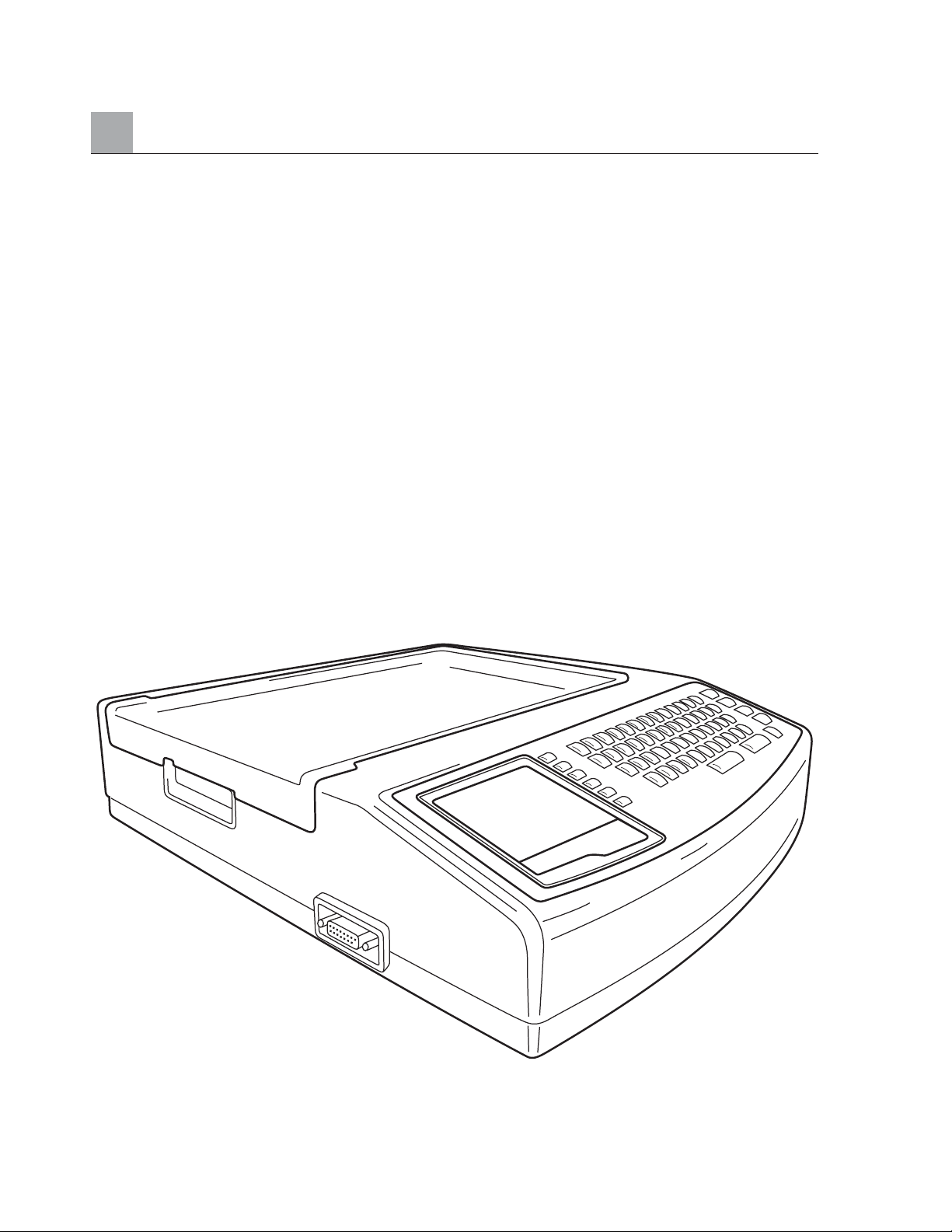
SECTION 1
System Description
The ELI 250 is a 12-lead diagnostic electrocardiograph capable of viewing, acquiring, printing, and storing
ECG data. The ELI 250 is optionally equipped with Mortara’s VERITAS 12-lead resting interpretation
algorithm. If this option is enabled, the VERITAS ECG algorithm can provide an over reading physician
with a silent second opinion through diagnostic statements output on the ECG report. For additional
information on the Mortara VERITAS resting interpretation algorithm, please refer to the Physician’s
Guide to ECG Interpretation.
Multiple print formats are supported including: 3+1, six, 3+3, twelve, and 6+6 channels in automatic mode and
six or twelve channels during rhythm recording. The ELI 250 can operate on battery or line power.
The ELI 250 electrocardiograph includes:
• Patient Cable
• Hospital Grade Power Cord
•1 pack paper (standard or A4)
•User’s Manual
•Optional Accessory Starter Kit
ELI 250, System Illustration
Figure 1-1
1-2
Page 19
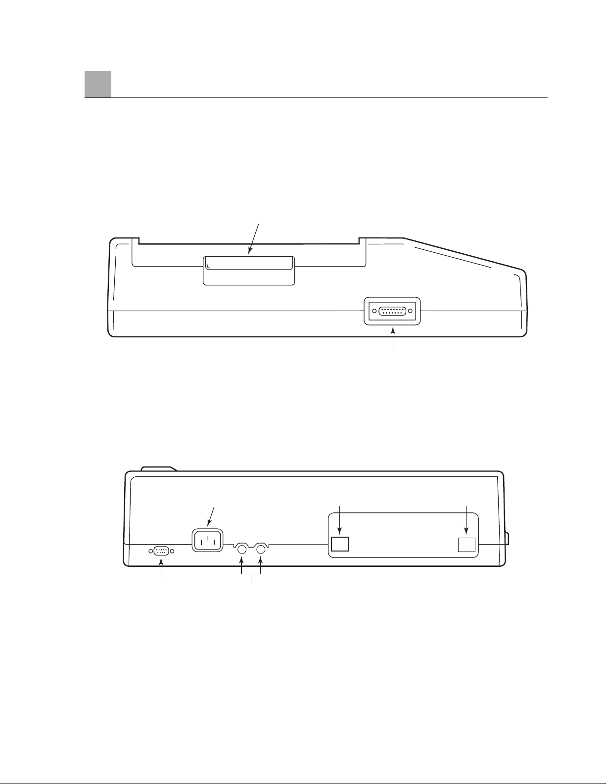
System Layout
ELI 250, Left Side
Figure 1-2
Left Side View
ELI 250, Rear
Figure 1-3
SECTION 1
1-3
Writer Cover Handle
Input Connector
(Patient Cable Connector)
AC (Powercord) Connector
AC FusesSerial Connector
RJ45
LAN
(Optional)
Modem Connector
(Optional)
Page 20
SECTION 1
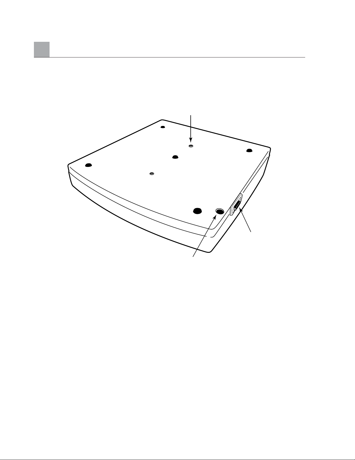
ELI 250, Base
Figure 1-4
1-4
Cart Mounting
Battery Fuse
ECG Imput
Page 21
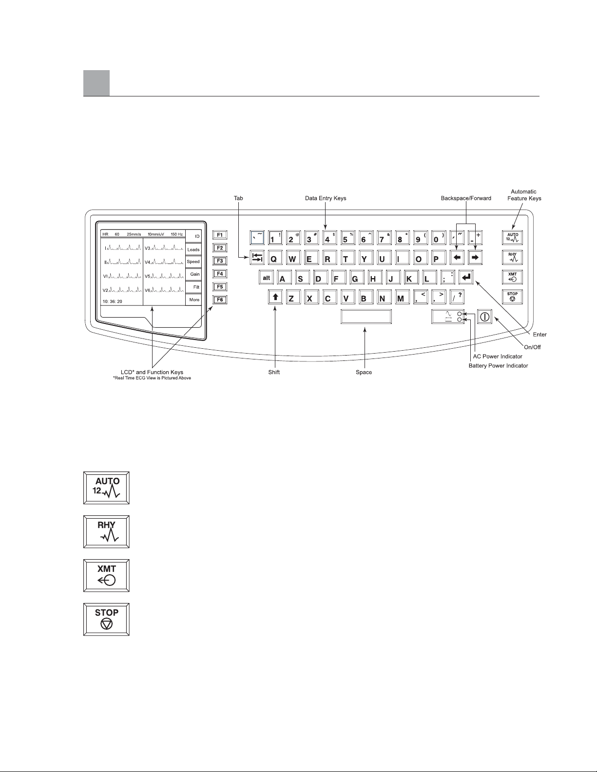
ELI 250, Display and Keyboard
Figure 1-5
Function Keys activate the liquid crystal display (LCD) label adjacent to each function key. LCD
la
bels/functions change depending upon the screen displayed. If the label is blank, the adjacent function
key is deactivated.
Automatic Feature Keys are used as a one-touch operation for:
ECG Acquisition
Rhythm Printing
Transmitting
Stop
SECTION 1
1-5
Page 22
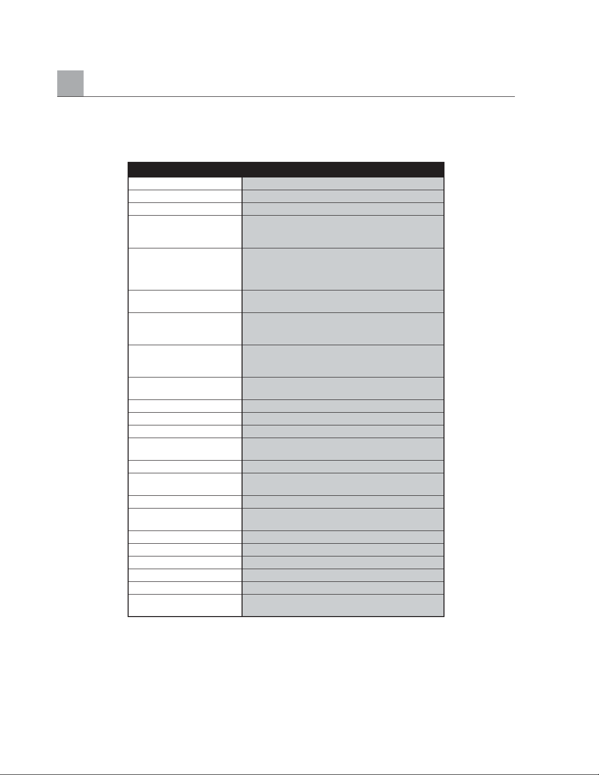
ELI 250 Specifications
SECTION 1
1-6
Feature Specifications
Instrument Type 12-lead Electrocardiograph
Input Channels Simultaneous acquisition of 12 leads
Standard Leads Acquired I, II, III, aVR, aVL, aVF, V1, V2, V3, V4, V5, V6
Waveform Display Backlit, 1/4 VGA LCD
3-channel lead groups or complete
8-channel presentation
Input Impedance Meet or exceed the requirements of
Input Dynamic Range ANSI/AAMI EC11
Electrode Offset Tolerance
Common Mode Rejection
Patient Leakage Current Meet or exceed requirements of ANSI/AAMI ES1
Chassis Leakage Current
Digital Sampling Rate 10,000 s/sec/channel used for pacemaker spike
detection; 1000 s/sec/channel used for recording
and analysis
Special Functions Optional Mortara VERITAS resting interpretation
algorithm; connectivity options for bi-directional
communication; flash memory storage of ECGs
Paper Type Full size (8.5" x 11" or A4), Z-fold thermal paper;
250 sheets stored in paper tray
Thermal Recorder Computer-controlled dot array; 8 dots/mm
Thermal Writer Speeds 5, 10, 25, or 50 mm/s
Gain Settings 5, 10, or 20 mm/mV
Report Print Formats
Standard or Cabrera:
3+1, 3+3 channel, 6-channel,
12-channel
Rhythm Print Formats
6-channel with configurable lead groups, or 12-channel
Keyboard Type Elastomer keypad with complete alphanumeric
keys, soft-key menu and dedicated function keys
Frequency Response 0.05 to 300 Hz
Filters High performance baseline filter; AC interference
filter 50/60 Hz; low pass filters 40 Hz or 150 Hz
A/D Conversion 20 bit (1.17 microvolt LSB)
Device Classification Class I, Type CF defibrillation proof applied parts
ECG Storage Up to 60 ECGs; optional expanded up to 150 ECGs
Weight 11.25 lb. (5.1kg) including battery
Dimensions 15.5" x 17" x 4" (39.4 cm x 43.2 cm x 10.2 cm)
Power Requirements Universal AC power supply (100-240 VAC at
50/60 Hz) 50 VA. Internally rechargeable battery
Page 23

Chapter Purpose
This chapter is intended to provide the user with:
• Equipment set-up procedures:
• Load paper
• Apply power
• Set date and time
• Patient preparation and hook-up
• Real-Time ECG View
Equipment Set-Up
Two AC line fuses and one battery fuse are installed on your ELI 250.
GETTING STARTED
SECTION 2
2-1
Page 24
SECTION 2
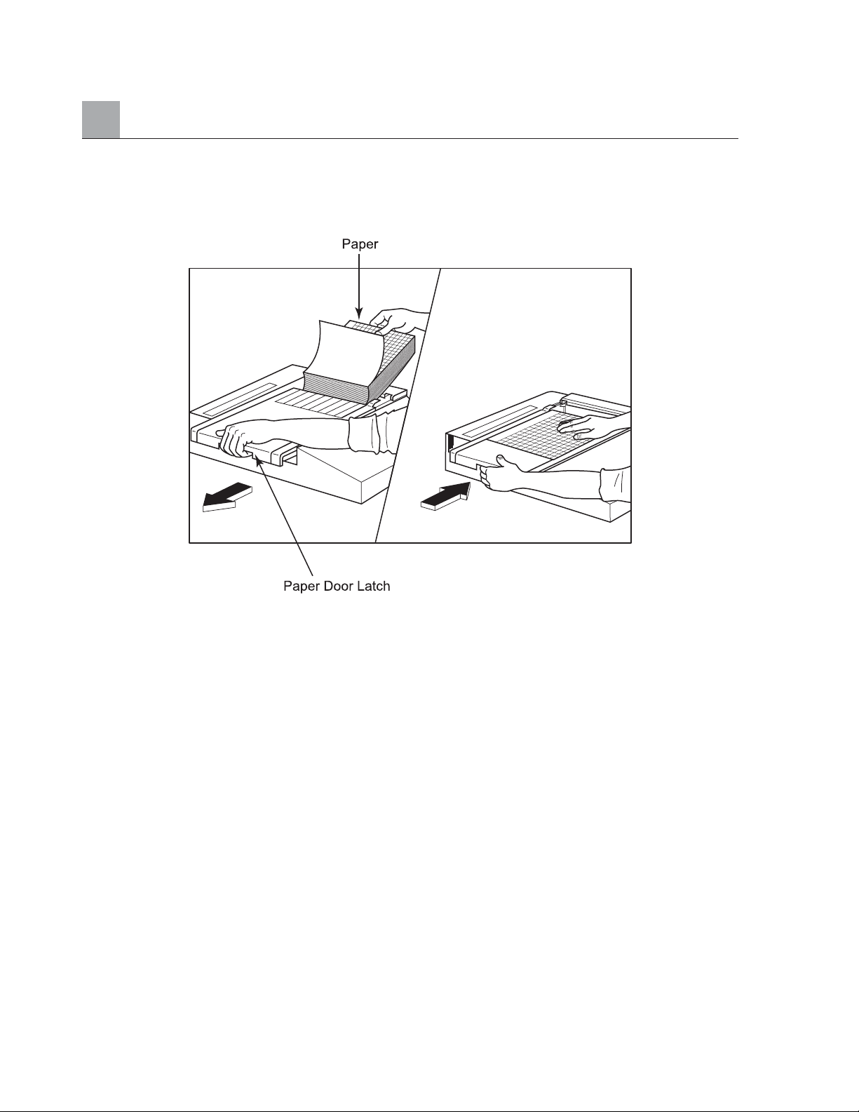
To load paper:
❶ Remove the outer packaging from the paper stack.
❷ Facing the front of the unit, use the release latch on the left side and slide the paper tray cover to the left.
❸ Place the stack of thermal paper into the paper tray such that the grid side of the paper is up when it is pulled
over the paper tray cover. The paper cue mark (a small black rectangle) should be in the lower left corner.
❹ Manually advance one page of paper beyond the closure point of the writer. Make sure the paper lays on
the black roller evenly within the channel of the paper door. If paper is not manually advanced evenly, risk
of jamming or queue faults increases.
➎ Slide writer cover to the right until the cover latches in a locked position. You will hear a sharp click when
the door is properly latched.
NOTE: The paper tray spacer should not be inserted if using standard size paper.
WARNING: Risk of injury to fingers in writer paper door or platen drive mechnisms.
2-2
Page 25
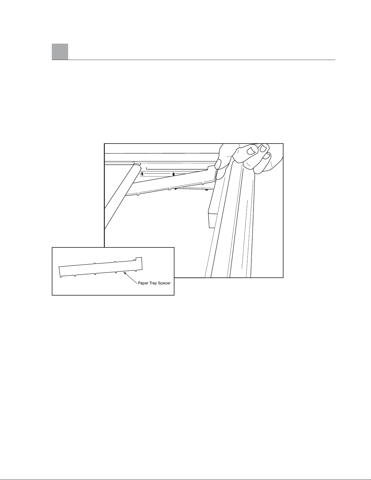
A4 paper users:
If your ELI 250 was ordered with A4 paper, the paper tray spacer will be inserted in the paper tray and the
configuration option to use A4 paper will be set to YES. If units are purchased with standard paper, the paper
tray spacer will not be provided.
To insert the Paper Tray Spacer:
❶ Slide paper tray spacer towards rear wall of writer tray. Align the bottom four plastic arms with the four
openings in the base of the writer tray. Similarly, align the top 3 plastic arms with the three openings on
the rear wall of the writer tray.
SECTION 2
2-3
Page 26
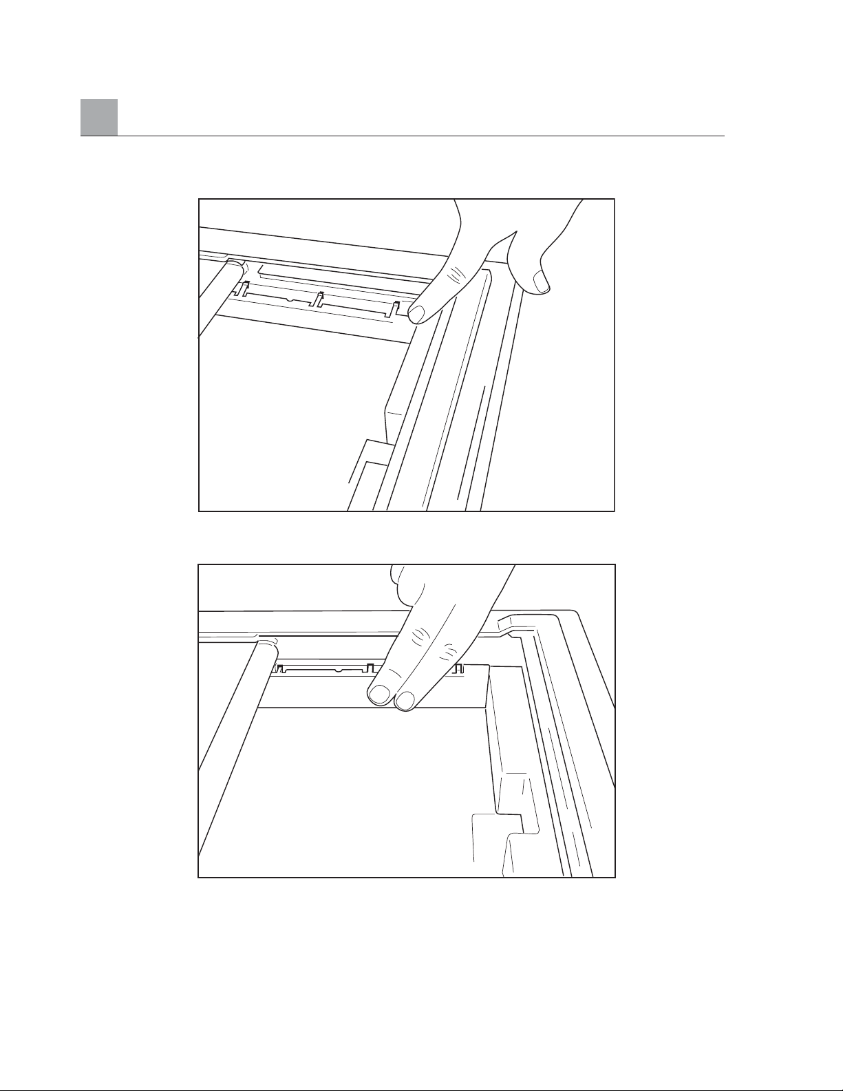
SECTION 2
❷ The paper tray spacer should be parallel with the rear wall of the writer tray, as pictured above.
❸ Gently press paper tray spacer in place.
❹ Set configuration option to use A4 paper. See section 3 for instructions.
➎ Gently press on the top three plastic arms to remove the paper tray spacer.
2-4
Page 27
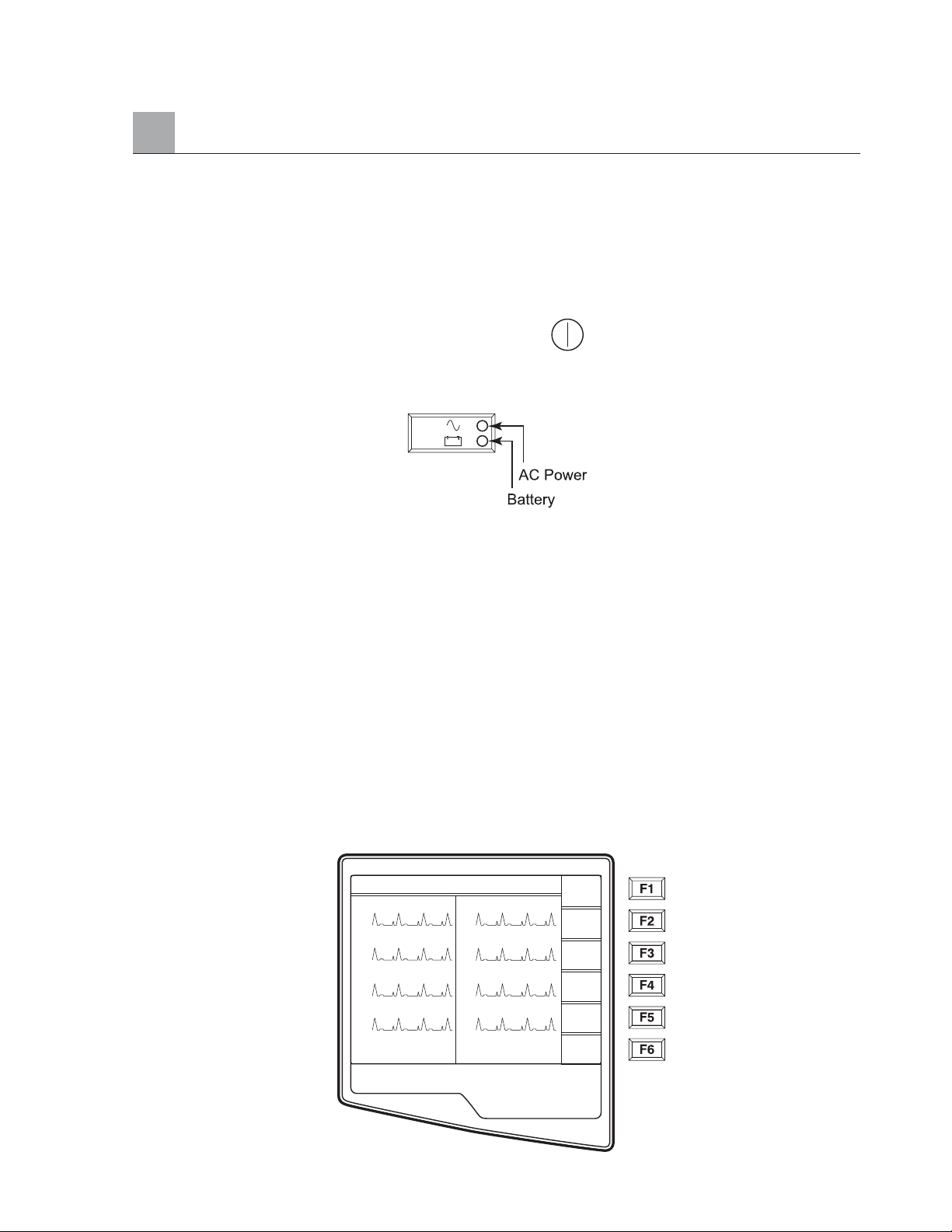
To Apply Power to the Electrocardiograph:
❶ Plug the power cord into an AC wall outlet and into the back of the ELI 250.
(Reference Figure 1-3). Unit powers on automatically and can not be turned off when AC is
connected (unit is in Stand by Mode).
❷ If using battery power, press the power on/off button located on the lower right side of the
keyboard. (Reference Figure 1-5).
Indicators on the Keyboard will Illuminate as Follows:
The AC power indicator illuminates when unit is connected to mains (AC power).
The battery power indicator illuminates when charging and flashes when battery is low (below 11.0 V).
The battery power indicator will turn off when the battery is fully charged.
The electrocardiograph should be connected to AC power for recharging whenever the unit is not in use.
TIP: Battery voltage is displayed at the bottom of Time/Date screen – see below.
NOTE: For typical usage, battery charging time should be approximately 8 hours or less.
CAUTION: When the battery charge is depleted to its lowest level (9.5V), the unit will automatically
power down. To recharge a battery from its lowest level, 30 hours of recharging without operation will
be necessary. Routinely discharging a battery to this level will severely shorten the life of the battery.
To Set the Time/Date and LCD Contrast:
❶ Select More (F6) from the Real-Time ECG View.
SECTION 2
2-5
HR 60 25mm/s 10mm/uV 150 Hz
I
II
VI
V2
10: 36: 20
V3
V4
V5
V6
ID
Leads
Speed
Gain
Filt
More
Page 28
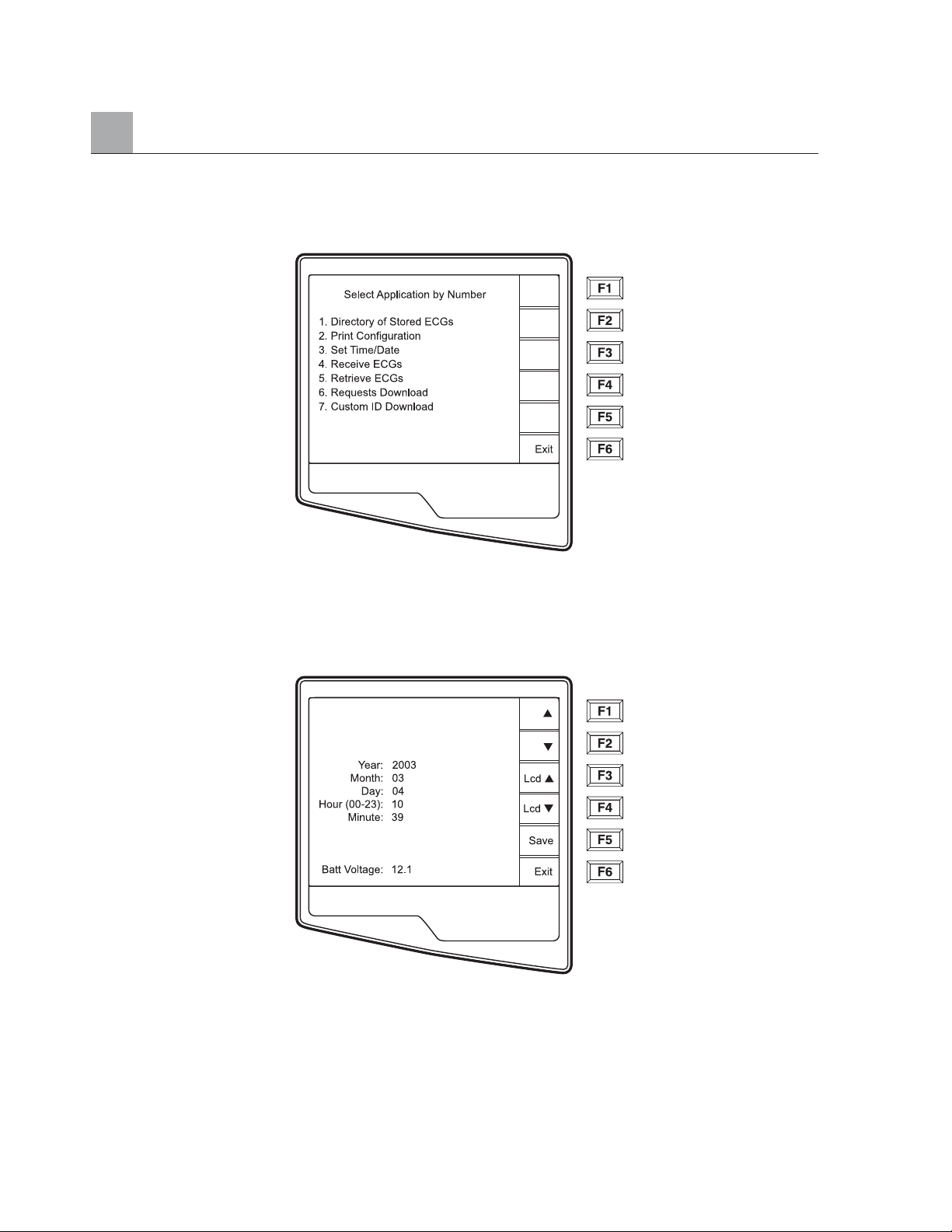
SECTION 2
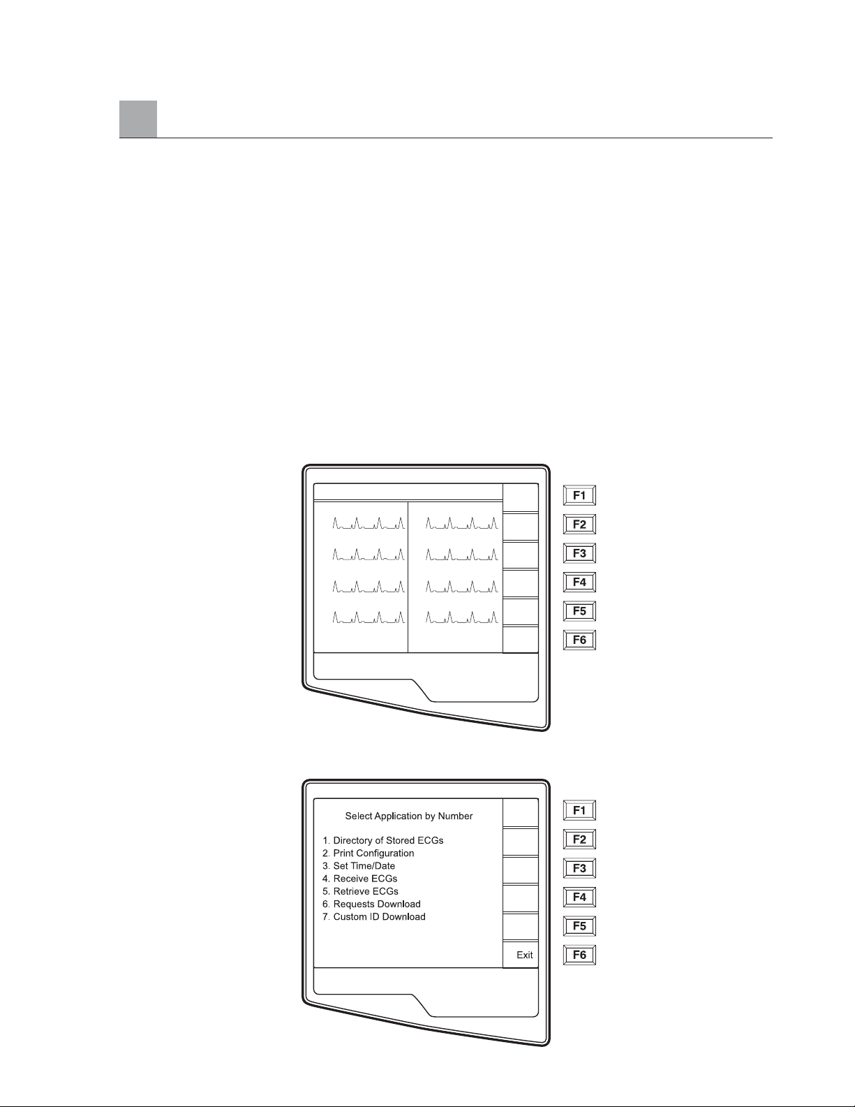
❷ Select number 3 (Set Time/Date) from the Application menu.
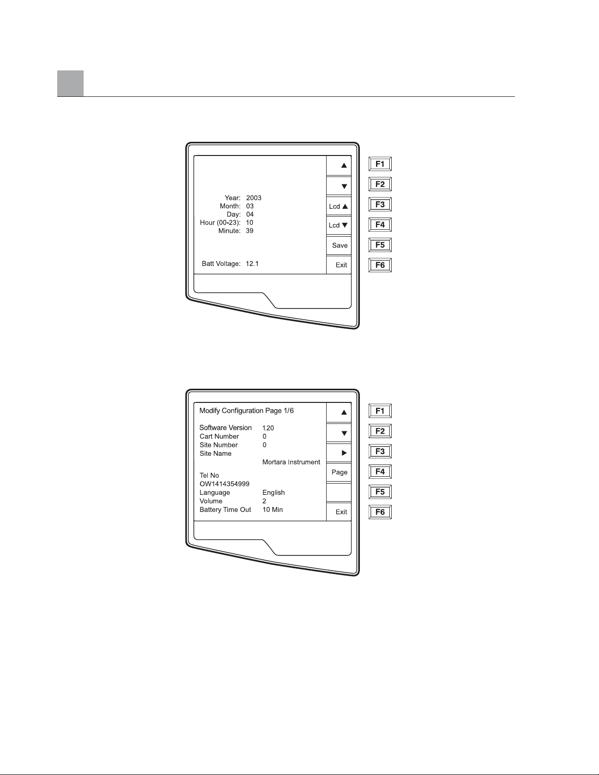
❸ The preprogrammed date and time is displayed for the ELI 250. To make changes, type in the desired date
and time values (using a 24-hour clock) in the same format as displayed. Use (F1) and (F2) to move back
and forth through each row.
TIP: Use the BACKSPACE key to erase entry errors.
❹ Select Save (F5) to save changes before exiting.
➎ Select Exit (F6) to return to Real-Time ECG View. If you did not save before selecting Exit, any changes
made to the Time/Date will be lost.
NOTE: LCD contrast can be adjusted by selecting Lcd (F3) or Lcd (F4).
TIP: The battery voltage value is displayed at the bottom of this screen.
2-6
➔
Page 29
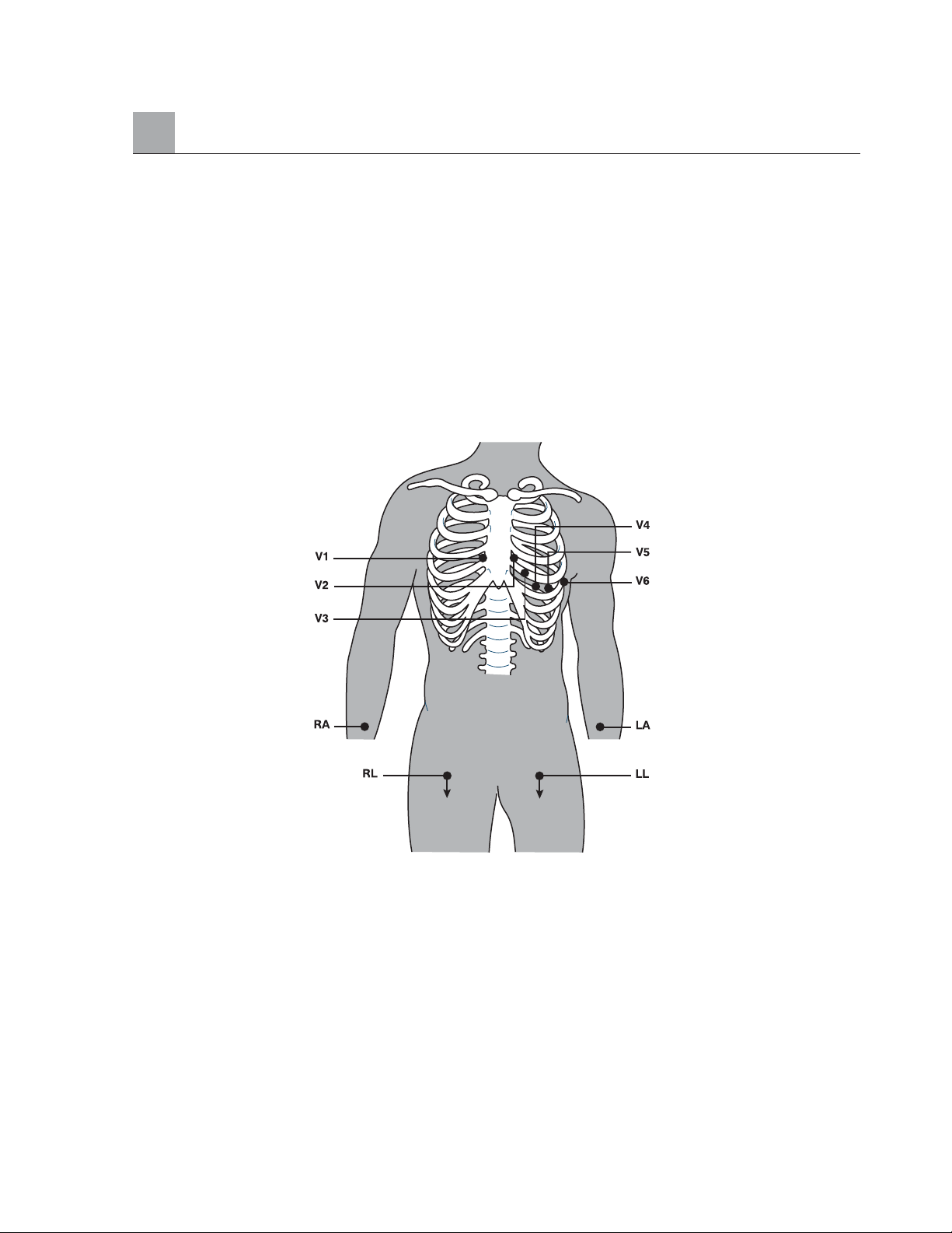
Patient Preparation
Correct electrode placement is important for acquiring a successful ECG (see Patient Hookup below).
Consider performing some patient preparation procedures to remove oils, lotions, and hair from the skin.
Optimal skin preparation includes exposing skin on hairy areas, scratching with abrading pad, wiping with
alcohol and a dry gauze pad.
TIP: Electrodes should be stored in an air-tight container. Electrodes will dry out if
not stored properly which will cause loss of adhesion and conductivity.
Patient Hookup
V1 Fourth Intercostal space at the right sternal border
V2 Fourth Intercostal space at the left sternal border
V3 Midway between V2 and V4
V4 Fifth intercostal space at the left of the midclavicular line
V5 Anterior axillary line at same horizontal level as V4
V6 Mid-axillary line on same horizontal level as V4 and V5
RA Right deltoid or wrist
LA Left deltoid or wrist
RL Right thigh or ankle
LL Left thigh or ankle
SECTION 2
2-7
LA
LA
Page 30
SECTION 2
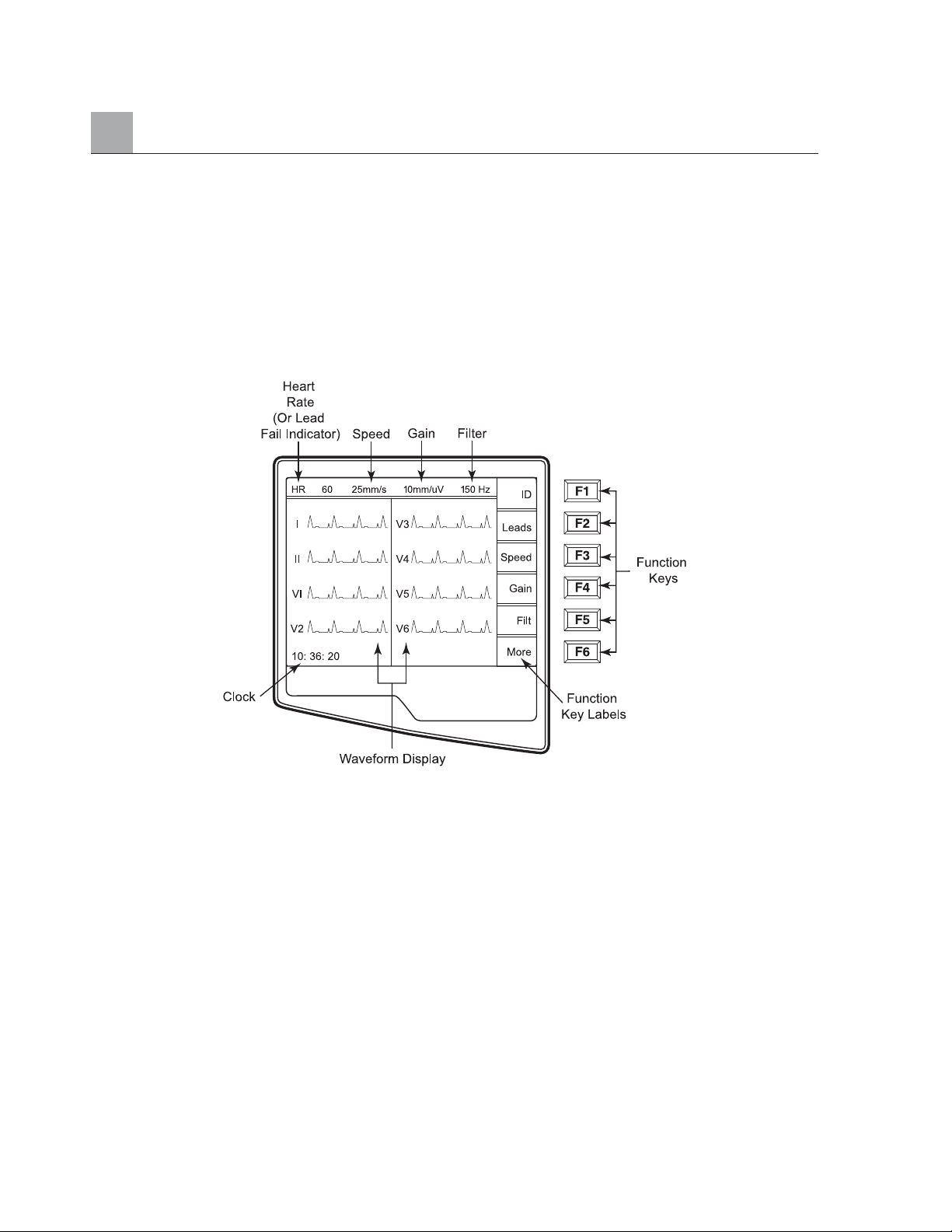
Real-Time ECG View
The ELI 250 LCD display offers the user valuable information including waveform display, function keys
and parameters (leadfail messages, clock, filter, etc.). Detailed descriptions of the Real-Time ECG View
are offered in section 4.
NOTE: Regardless of the display, function keys always correspond to the LCD label
adjacent to each function key.
2-8
Page 31
Chapter Purpose
This chapter is intended to provide the user with:
• Instructions to access configuration menus
• Summary of configuration options
• Detailed descriptions of configuration settings
Access Configuration Menus
The configuration pages define all ELI 250 operational conditions that do not change on a daily or
patient-to-patient basis. Once you set these default conditions, you will rarely need to use the configuration
screens again. When you apply power to the ELI 250, it will operate according to the settings you have
selected. To access the configuration menus:
❶ Select More (F6) from the Real-Time ECG View.
❷ Select Set Time/Date (number 3) from the application menu
SYSTEM SETTINGS
SECTION 3
3-1
HR 60 25mm/s 10mm/uV 150 Hz
I
II
VI
V2
10: 36: 20
V3
V4
V5
V6
ID
Leads
Speed
Gain
Filt
More
Page 32
SECTION 3
❸ From the Set Time/Date screen, simultaneously press (SHIFT) + ALT + C.The first
configuration screen will appear. Notice the page indicator in the upper right hand corner
on each screen.
NOTES: Use Page (F4) to toggle through the configuration pages.
Use ▲(F1) and ▼(F2) to move back and forth through each configuration option.
Use (F3) to toggle through pre-programmed available settings per configuration field.
Use Exit (F6) to return to the Real-Time ECG View. Any changes you have made
will be saved.
Use the BACKSPACE key to erase entry errors.
The following chart summarizes the configuration screens and the available options for each parameter.
3-2
➔
▲
➔
Page 33

Summary of Configuration Menus
SECTION 3
3-3
Configuration Parameter Definition Configuration Screen
Software Version The firmware version of the unit Screen One
Cart Number User-defined (6 digits) Screen One
Site Number User-defined (4 digits) Screen One
Site Name User-defined (up to 30 alphanumeric characters) Screen One
Telephone Number User-defined (up to 30 alphanumeric characters) Screen One
Language Firmware language availability Screen One
Volume Range from 0 – 8 Screen One
Battery Timeout 10min, 30min, 60min Screen One
Flash Size Normal memory or Expanded memory (optional) Screen Two
ID Format Short, Long, Standard, Custom (optional) Screen Two
Auto-Fill ID Yes or No Screen Two
AC Filter None, 60Hz, 50Hz Screen Two
Paper Speed 25mm/sec or 50 mm/sec Screen Two
Filter 40Hz, 150Hz, or 300Hz Screen Two
Height/Weight Units lb/in or kg/cm Screen Two
Date Format US (mm/dd/yyyy) or European (dd.mm.yyyy) Screen Two
Plot Format Channels printed: 3+1, 6, 3+3, 12, 6+6; Screen Two
Cabrera or Standard
Interpretation Yes or No Screen Two
Reasons Yes or No Screen Two
Append Unconfirmed report Screen Three
#of copies 0 - 9 Screen Three
#ECGs retrieved 0 - 9 Screen Three
Delete Rule Post plot, post transmit, post plot/xmt Screen Three
Storage Sensitivity Normal or High Screen Three
Auto-save ECG Yes or No Screen Three
Auto-print ECG Yes or No Screen Three
Baud Rate Serial Baud Rates: 9600, 19200, 38400, Screen Three
57600, or 115200
Use A4 paper Yes or No Screen Three
Caps Lock Yes or No Screen Three
Rhythm Format 3 channel, 6 channel or 12 channel Screen Four
3 Rhythm Lead 1 V1-V6, I, II, III, aVR, aVL, aVF Screen Four
3 Rhythm Lead 2 V1-V6, I, II, III, aVR, aVL, aVF Screen Four
3 Rhythm Lead 3 V1-V6, I, II, III, aVR, aVL, aVF Screen Four
Page 34

SECTION 3
Summary of Configuration Menus (Continued)
3-4
Configuration Parameter Definition Configuration Screen
6 Rhythm Lead 1 V1-V6, I, II, III, aVR, aVL, aVF Screen Four
6 Rhythm Lead 2 V1-V6, I, II, III, aVR, aVL, aVF Screen Four
6 Rhythm Lead 3 V1-V6, I, II, III, aVR, aVL, aVF Screen Four
6 Rhythm Lead 4 V1-V6, I, II, III, aVR, aVL, aVF Screen Four
6 Rhythm Lead 5 V1-V6, I, II, III, aVR, aVL, aVF Screen Four
6 Rhythm Lead 6 V1-V6, I, II, III, aVR, aVL, aVF Screen Four
3 + 1 Rhythm Lead V1-V6, I, II, III, aVR, aVL, aVF Screen Five
3 + 3 Rhythm Lead 1 V1-V6, I, II, III, aVR, aVL, aVF Screen Five
3 + 3 Rhythm Lead 2 V1-V6, I, II, III, aVR, aVL, aVF Screen Five
3 + 3 Rhythm Lead 3 V1-V6, I, II, III, aVR, aVL, aVF Screen Four
Default XMT Media RS232, Modem, WLAN, LAN, external modem Screen Six
Barcode Reader Yes or No Screen Six
DHCP Yes or No Screen Six
IP Address XXX.XXX.XXX.XXX Screen Six
Def Gateway XXX.XXX.XXX.XXX Screen Six
Sub Net Mask XXX.XXX.XXX.XXX Screen Six
Host IP XXX.XXX.XXX.XXX Screen Six
Port Number XXX.XXX.XXX.XXX Screen Six
SSID Yes or No Screen Six
Channel Number 0, 1, 2, 3 Screen Six
Security WEP Yes or No Screen Seven
WEP Key 0, 1, 2, 3 Screen Seven
WEP Key ID 26 digits in 13 sets of two digits Screen Seven
Page 35
Configuration Page 1
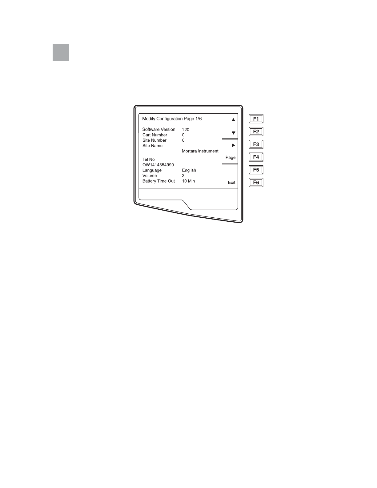
Software Version
The displayed number identifies the firmware version of your electrocardiograph.
Cart Number
Cart numbers indicate which electrocardiograph transmitted a particular ECG.
Site Number
This option identifies the site of your ELI 250. Site numbers designate the hospital, clinic, or institution for
ECG records stored in a Mortara Instrument E-Scribe data management system and must be defined for
transmitting and retrieving ECGs from the data management system. You can use up to four digits for the
site number, numbers from 0 – 4095 are supported
Site Name
This option defines your clinic, hospital, or office name. You can enter up to 30 alphanumeric characters.
The site name prints at the bottom, left edge of the ECG printout.
SECTION 3
3-5
Page 36

SECTION 3
3-6
Telephone Number
This option specifies the telephone number for modem transmission (to another unit or to an E-Scribe
data management system). Enter up to 30 alphanumeric characters, and use the BACKSPACE key to
erase entry errors.
To wait for an additional dial tone, use the letter W.For example, you may need to dial a 9 to get an
outside line.
EXAMPLE: 9W14145554321
To insert a pause use a comma (,).
To change tone dialing to pulse dialing, use the letter P.
EXAMPLE: P14145554321
(If necessary, you can use both the letter W and the letter P in the same phone number.)
TIP: Instead of entering the configuration menus, use a shortcut to quickly delete or modify a
phone number. From the application screen, simultaneously press (SHIFT) + ALT + P.
To edit an existing telephone number, use the tab key.
Language
There are several languages available on the cardiograph.
CAUTION: Upon selecting a new language and exiting the configuration screen, function
labels are immediately translated.
If an unknown language is visible, use the following steps to revert to the language of your country:
1. F6 from Real-Time ECG View
2. Select number 3
3. Simultaneously press (SHIFT) + ALT + C
4. Press F2 (▼) four times
5. Press F3 ( ) until the desired language appears
6. F6 to return to Real-Time ECG View
Alphabets of specific languages may require the use special characters in demographic fields. This is
accomplished by selecting ALT + the letter. For example, ñ is entered by selecting ALT + n. Hold the
ALT key and scroll the letter to view the available letter selections with diacritics.
Volume
This option defines the keyboard click loudness. Available settings rage from 0 (off) to 8 (loud).
TIP: Use the BACKSPACE key to erase entry errors
Battery Timeout
This setting determines when the cardiograph will switch off in order to conserve the battery life of the unit.
The battery timeout will only occur if the keypad has not been depressed for the time specified. The battery
timeout setting is ignored if an active ECG signal is detected, during transmission, or while rhythm printing.
➔
➔
➔
▼
➔
Page 37
SECTION 3
Configuration Page 2
Flash Size
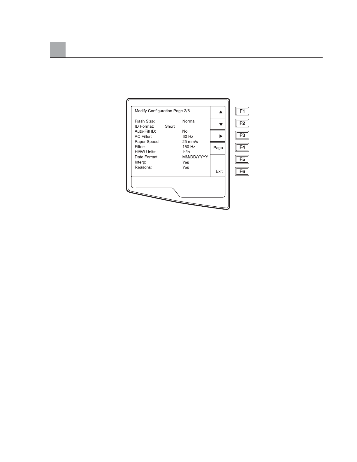
Flash Size indicates the ECG storage capacity of your electrocardiograph. Normal Flash Size is the standard
memory capacity. If the optional expanded memory has been installed, Expanded will be displayed.
ID Format
This option defines the format for the patient ID information prompts. There are three standard formats:
short, standard, or long. A custom ID format is optional when downloaded from the E-Scribe Data
Management System.
The short format includes the patient's last name and first name, patient ID number, date of birth, which will
automatically calculate the age, and gender field.
The standard format includes the patient's last name, patient ID number, age, height, weight, gender, race,
medication 1, medication 2, and a location field.
The long format is identical to the standard format except that it includes the patient's first name, room and
comment fields.
The custom format, which is designed in the Mortara E-Scribe Data Management System, can be downloaded
to the ELI 250. The custom ID format is uniquely designed to meet your facility’s needs. Please see Appendix
A to download a Custom ID.
3-7
Page 38

SECTION 3
3-8
Auto-Fill ID
When enabled, the system will automatically populate the demographic fields in the ID screen. When the
patient ID field is manually populated and followed either by selecting enter or F2 (▼) the system
automatically scans the patient directory and if records with the exact ID are found, the existing data is used to
fill some of the demographic fields. The auto-fill feature is designed to only automatically populate last name,
first name, date of birth, age and gender. If no matching records are found, a brief message is displayed and
the user must manually enter the patient’s demographics.
NOTE: In order to avoid the use of incorrect data, the Auto-Fill ID feature is only supported if
the ID formats are the same between records and if the records belong to the same site.
AC Filter
The ELI 250 removes 60Hz or 50Hz interference. The setting you select depends on the line frequency in your
country. Always use the 60Hz setting in the United States. If the AC interference is present, check to see that
the proper AC filter is selected.
Paper Speed
The writer speed can be configured at 25mm/s or 50mm/s for default ECG printouts. For rhythm
printouts and display, speeds of 5mm/s or 10mm/s are also available. See Section 4 to change speeds for
display or rhythm printing.
Filter
The ECG plot frequency filter (or print filter) can be set to 40Hz, 150Hz, or 300Hz. The plot frequency
filter does not filter the acquired digital record. A 40Hz plot filter setting will reduce the noise (40Hz and
higher frequencies) on the printed ECG, a 150Hz plot filter setting will reduce the noise (150Hz and
higher frequencies) on the printout and a 300Hz plot filter setting will not filter the printed ECG.
Height/Weight Units
This option defines the units of weight and height to either pounds/inches (lb/in) or kilograms/centimeters (kg/cm).
Date Format
This option defines the format for entering and displaying the patient’s date of birth in either the U.S. format
or the European format.
For example: July 16th, 2003 is displayed as follows:
US Date Format: MM/DD/YYYY (07/16/2003)
European Date Format: DD.MM.YYYY (16.07.2003)
NOTE: the date format option does not modify the acquisition date printed on each ECG.
Using the example above, the acquisition date would print as 16-Jul-2003.
Page 39
SECTION 3
3-9
Interpretation Option
The ELI 250 automatically analyzes ECGs and prints the optional interpretation on the ECG printout. This
option allows you to select or suppress the “interpretive” text on the ECG report.
NOTE: A qualified physician should review the computer generated ECG interpretation
before the treatment of any patient.
Reasons
The reason statements indicate why a particular interpretive statement was printed. Reason statements
print in [square brackets] within the interpretive text (if the interpretation is turned on). Turning the
reason statement function on or off does not affect the measurements performed or the interpretive
statements selected by the analysis program.
For Example:
Anteroseptal Infarct [40+ MS Q WAVE IN V1-V4]
Where “Anteroseptal Infarct” is the interpretive statement.
And “40+ MS Q WAVE IN V1-V4” is the reason statement or
explanation as to why the interpretive statement was printed.
Configuration Page 3
Append
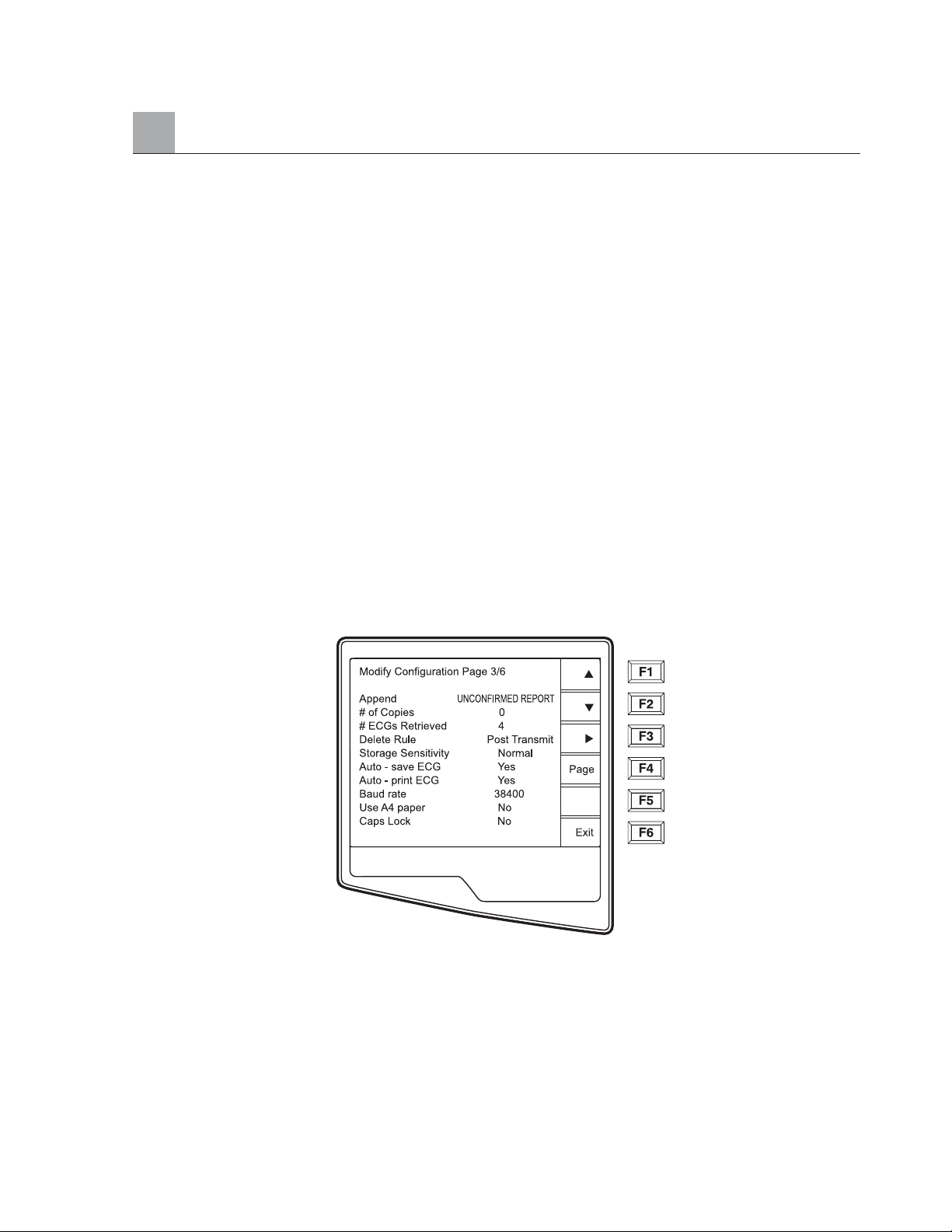
A status or statement phrase can be appended to the ECG and printed under the interpretive text printout.
Either “unconfirmed report” or “reviewed by” can be selected. However, if you wish to have nothing appended
to the ECG, “blank” may be selected.
Number of Copies
This option defines the number of printed copies when an ECG is taken. A zero (0) setting prints the original
only; one (1) prints the original plus 1 copy; two (2) prints the original plus 2 copies, and so on. Up to 9 copies
may be selected.
Page 40

SECTION 3
3-10
ECGs Retrieved
This option defines the number of ECGs retrieved from an E-Scribe data management system. The ECGs are
retrieved by ID number. A zero (0) setting retrieves the most current ECG for that ID number. Settings from
one (1) to nine (9) retrieve the most current ECG plus “X” number of ECGs identified by the entered value.
EXAMPLE: If you enter the number 5, you will retrieve the most current ECG plus the five preceding ECGs
for that ID number. ECGs retrieved from the E-Scribe are only printed at the ELI250 and not saved.
Delete Rule
This option defines the ECG auto delete status in the patient directory. ECGs that are marked for deletion
will be automatically removed or erased based on its date (a first in/first out philosophy) to make room
necessary for the new ECG record. ECGs are only erased from the directory when they are marked for
deletion and if the directory becomes full. More than one ECG may be removed from the directory in
order to make room for the the new incoming record. The delete rule selections are:
•Post Plot = ECG is automatically marked deleted after printing
•Post Transmit = ECG is automatically marked deleted after transmission
•Post Plot/Transmit = ECG is automatically marked deleted after transmission and printing
Storage Sensitivity
The ECG storage sensitivity setting dictates the resolution of the stored record. The sensitivity settings are
either Normal or High. If the configuration value is set to High, the stored ECG will have a high resolution.
As a result, the records size will be large and will reduce the storage capacity in the ECG directory.
Auto Save ECG
This option defines whether or not the ELI 250 is to automatically save newly acquired ECGs in the directory,
once they are acquired and printed. If the auto save configuration option is set to NO, and the record is printed,
the ELI 250 will prompt you to “Save ECG?” Save (F1) will store the ECG in the directory.
NOTE: Manually save ECGs by selecting More (F5) from the Acquired ECG
view and Save (F5).
Auto Print ECG
This option defines whether or not the ELI 250 will automatically print the ECG after acquisition. If the
selected configuration option is set to NO, a manual printout is possible after acquisition.
Baud Rate
The user-selectable baud rate determines the serial port’s data transmission rate in bits per second (bps).
Set the baud rate to: 9600, 19200, 38400, 57600, or 115200 bps for direct data transmission between the
ELI 250 and another Mortara cardiograph, and 38400 bps for a direct connection to the E-SCRIBE data
management system.
Page 41
SECTION 3
3-11
Use A4 Paper
The ELI 250 accommodates use of Z-fold thermal paper in either the letter size (8.5 x 11 inches; 216 x 279 mm)
or the “A4” size (8.27 x 11.69 inches; 210 x 297 mm). The provided paper tray spacer is required for use with A4
size paper. Enable this configuration option for A4 printing. The paper tray spacer should not be inserted if the
letter size paper is used.
Caps Lock
All character entry is translated to upper case.
Configuration Page 4
Rhythm Formats
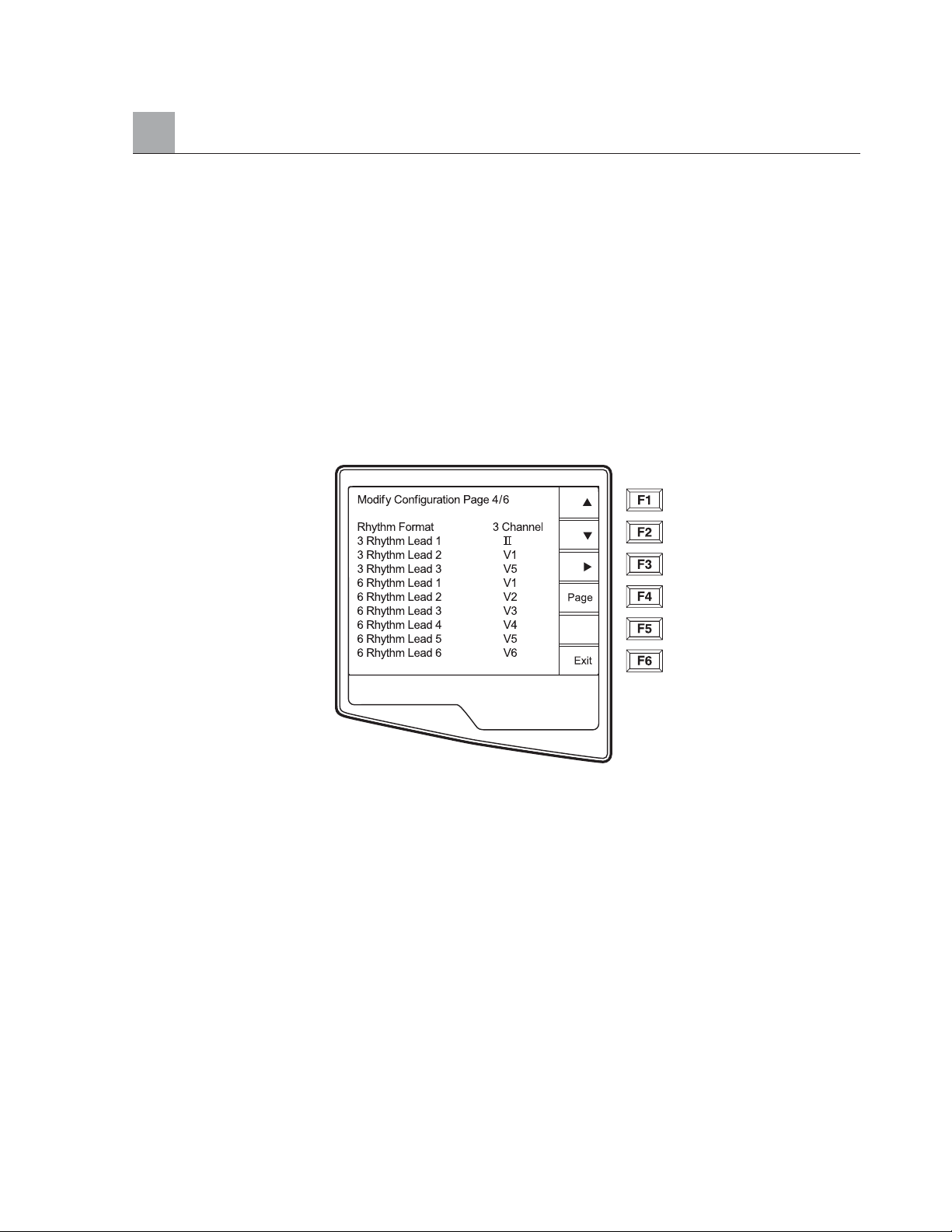
Configuration page four defines the default values for rhythm printing. It is possible to set a 3-channel,
6-channel or 12-channel default rhythm format. Define rhythm leads one through three to customize a
three-channel rhythm printout or define rhythm leads one through six to customize the six-channel
rhythm printout. Use (F3) to toggle through each of the 12 leads.
Page 42
SECTION 3
3-12
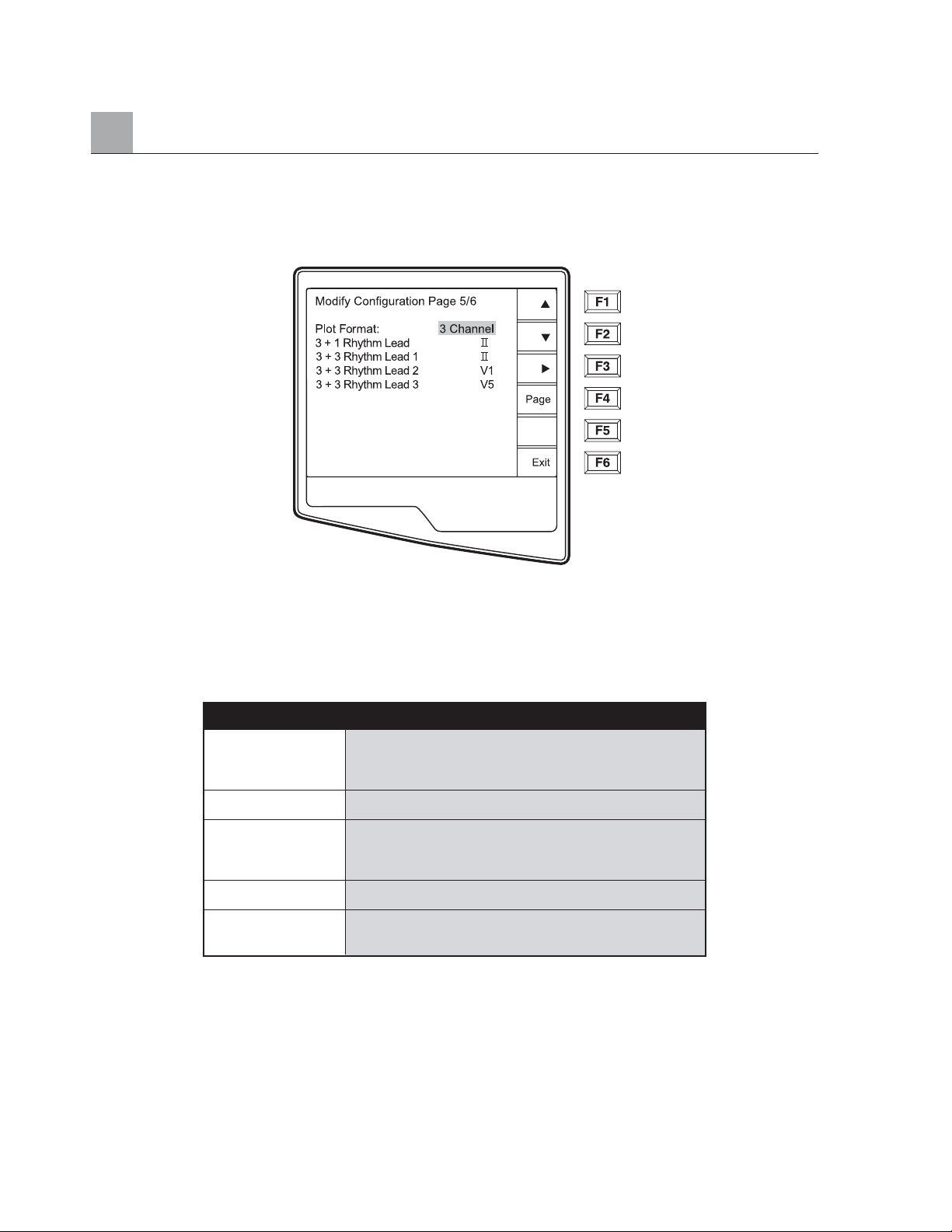
Configuration Page 5
Plot Format
This option defines the default for one of five available plot formats in either Standard or Cabrera presentation.
Please note that regardless of the plot format selected, 10 seconds of 12-leads are always stored.
The ECG plot options are:
Rhythm Leads
Configuration page four five also identifies the user-selectable 10-second rhythm lead printed in a 3 + 1 channel
ECG printout and the three 10-second rhythm leads for the 3+3 channel ECG printout. Use (F3) to make your
selection of any of the 12 leads.
NOTE: Rhythm acquisition is not stored in memory, only printed.
NOTE: See section 4 to acquire a rhythm printout.
Format Option ECG Data
2.5 seconds of 12 leads in a three-channel format
3+1 and the fourth channel is a 10 second rhythm strip
of lead II (user defined).
65 seconds of 12-leads in a six-channel format
2.5 seconds of 12 leads in a three-channel format
3+3 plus 10 second rhythm strip of leads II, V1 and V5
(user defined) in a three-channel format.
12 10 seconds of 12 leads in a 12 channel format
6+6 10 seconds of 12 leads in a 2 page printout
(six channels per page)
Page 43

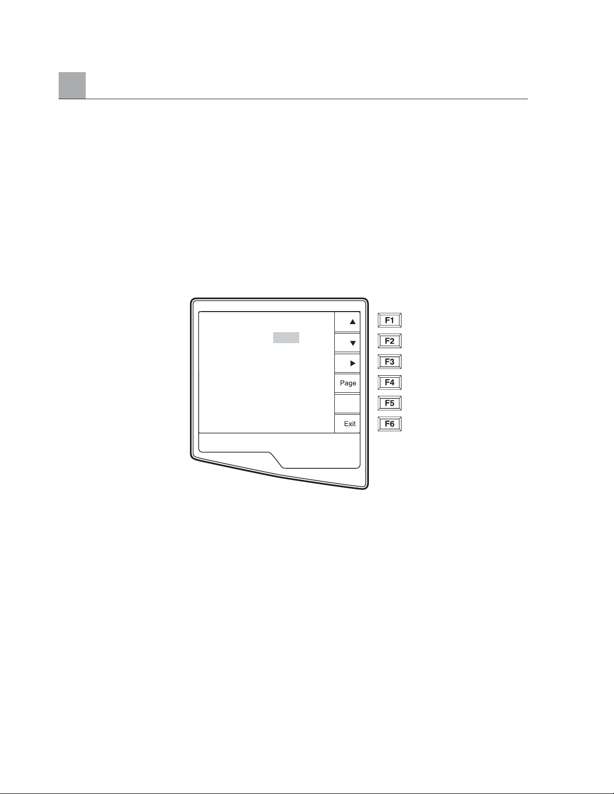
Configuration Page 6 (optional LAN connectivity)
The ELI 250 connectivity options are RS232 (or direct), modem, LAN or WLAN. Configuration parameters
associated with each type of transmission media will be presented in configuration pages six and seven only if
those media are installed in the cardiograph.
Default XMT Media
Configuration page 6 identifies the default transmission media. Those connectivity options which have been
optionally purchased and installed (RS232, modem, LAN or WLAN) in your ELI 250 will be available for
default selection.
DHCP
This setting defines whether the Dynamic Host Communication Protocol (DHCP) will be used to obtain an IP
address. If DHCP is Yes, the network will automatically and dynamically assign an IP address therefore, there
is no need to manually enter an IP address. If DHCP is No, you must enter the IP address, Def Gateway and
Sub Net Mask.
NOTE: All parameters related to network connection must be entered under the direction of
the IT Manager of the facility where the unit is installed.
IP Address
Define the fixed IP address used by the ELI 250 for network transmission (if DHCP is not selected).
Def Gateway
Enter the address of the default gateway (if DHCP is not selected).
Sub Net Mask
Enter the Sub Net address (if DHCP is not selected).
SECTION 3
3-13
Page 44
SECTION 3
Host IP
Enter the IP address of the host server.
NOTE: Addresses are always entered as 4 sets of 3 digits; therefore, an address of 192.168.0.7
must be entered on the ELI 250 as 192.168.000.007.
Port Number
Enter the port number used by the host server.
Configuration Page 6 (optional WLAN connectivity), (Continued)
SSID
Service Set Identifier (SSID) is the name of the wireless network. All ELI 250 electrocardiographs that will
transmit to the same network must have the same SSID name. This field is case sensitive.
Channel Number
This defines the channel used by the radio to search for the network. The exact channel number varies
according to which type of wireless network is used and the country in which you install the WLAN. When
moving from one area to another, the ELI 250 WLAN card will automatically scan for the channel of the
closest access point.
3-14
Modify Configuration Page 6/7
Default XMT Media: W LAN
DHCP: No
IP Address: 000.000.000.000
Def. Gateway: 000.000.000.000
Sub Net Mask: 000.000.000.000
Host IP: 000.000.000.000
Port Number: 0
SSID:
No SSID:
Channel Number 6
Page 45
Configuration Page 7 (optional WLAN connectivity), (Continued)
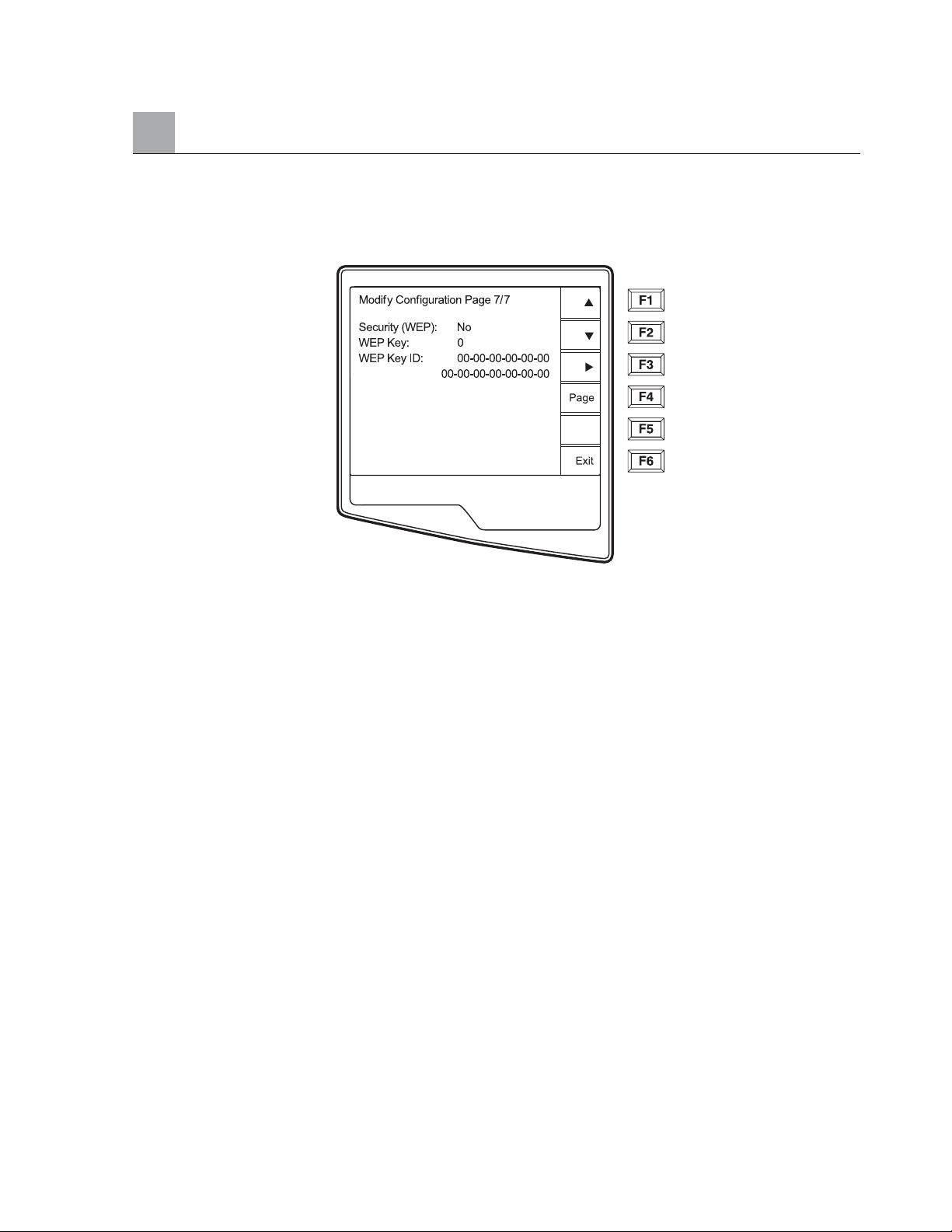
Security (WEP)
Wired Equivalent Privacy (WEP) is an encrypted security protocol, part of the 802.11 standard, and is used to
protect the network from unauthorized users. The IT Manager will provide the 26 HEX digits that are the
same to be used by all access points on the network. Therefore, only devices with the proper WEP will be able
to login. The ELI 250 adopts a 128-bit encryption. Access points can have multiple WEP Keys stored. Each
one of them is identified by a number (e.g., 0, 1, 2, 3).
WEP Key
Enter the WEP Key number (e.g., 0, 1, 2, 3).
WEP Key ID
Enter the 128-bit WEP Key ID value (26 digits in 13 sets of two digits).
SECTION 3
3-15
Page 46

SECTION 3
3-16
Page 47
Chapter Purpose
This chapter is intended to provide the user with:
• Display overview
• Overview of patient demographic entry
• Instructions to acquire an ECG
• Instructions to print an ECG
• Instructions to store an ECG
• Rhythm printouts
Display Overview
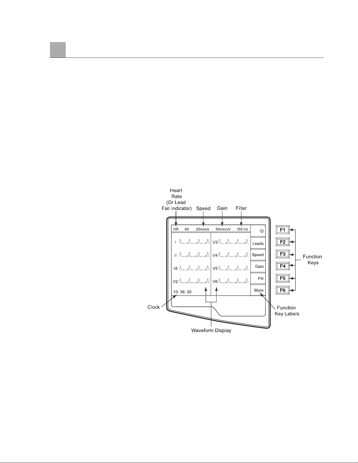
The ELI 250 features a 320 x 240 pixel LCD display for valuable preview of ECG waveform, function key
labels and other parameters as explained below:
• Heart Rate: When a patient is
connected to the cardiograph,
his/her heart rate is displayed
in real-time. The heart rate is
the average ventricular rate
measured over an average of
the patient’s last five beats.
NOTE: If a lead fail
occurs, an indicator
flashes in this location.
• Speed: Use Speed (F3) to
select one of the various options
for display speed or rhythm
printout speed: 5mm/s, 10mm/s,
25mm/s, 50mm/s.
NOTE: ECG paper speed
is configured in page two of
the configuration menus.
(See section 3). Paper speed is
printed at the bottom-right
corner of the ECG printout
• Gain: Use Gain (F4) to select waveform amplitude for display and printout: 5mm/mV, 10 mm/mV, 20 mm/mV.
Gain is printed at the bottom-right corner of the ECG printout.
•Filter: Use Filt (F5) to select the low-pass filter options: 40Hz, 150Hz, 300Hz for ECG printouts.
• Clock: Time display with hour, minutes and seconds resolution. (See section 2 for setting a new date
and time). When the ECG is acquired, the time displayed is the printed ECG acquisition time.
RECORD AN ECG
SECTION 4
4-1
Page 48
SECTION 4
Function keys always activate the corresponding LCD label adjacent to each key. LCD function key labels
change according to the ECG view - the Real-Time ECG View is pictured below and the Acquired ECG View
is described later in this section.
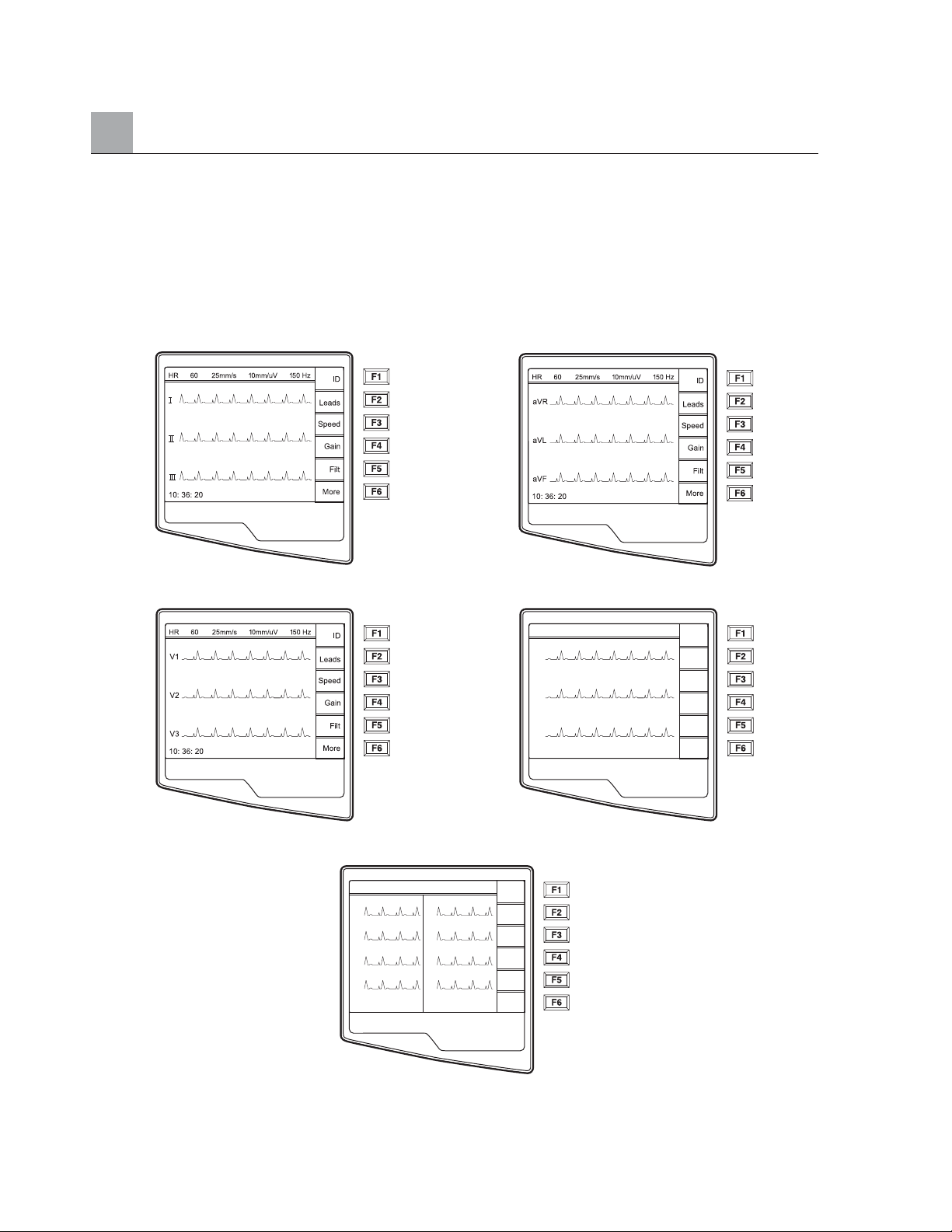
Toggle through the available waveform display formats by selecting Leads (F2). Waveforms are displayed in
the following formats:
5 seconds of leads I, II, III 5 seconds of leads aVR, aVL, aVF
5 seconds of leads V1, V2, V3 5 seconds of leads V4, V5, V6
2.5 seconds of leads I, II and V1-V6
(default display – only available in Real-Time ECG View)
4-2
HR 60 25mm/s 10mm/uV 150 Hz
V4
V5
V6
10: 36: 20
Leads
Speed
Gain
More
HR 60 25mm/s 10mm/uV 150 Hz
I
II
VI
V2
10: 36: 20
V3
V4
V5
V6
ID
Leads
Speed
Gain
Filt
More
ID
Filt
Page 49
Patient Demographics
You may enter patient demographic information before acquisition. The entered patient ID fields will remain
populated until you acquire the ECG. However, when you disconnect the leads from the patient, turn off the
cardiograph, or change a configuration setting before acquisition, the entered patient demographic information
will be cleared for you to enter the demographics of your next patient.
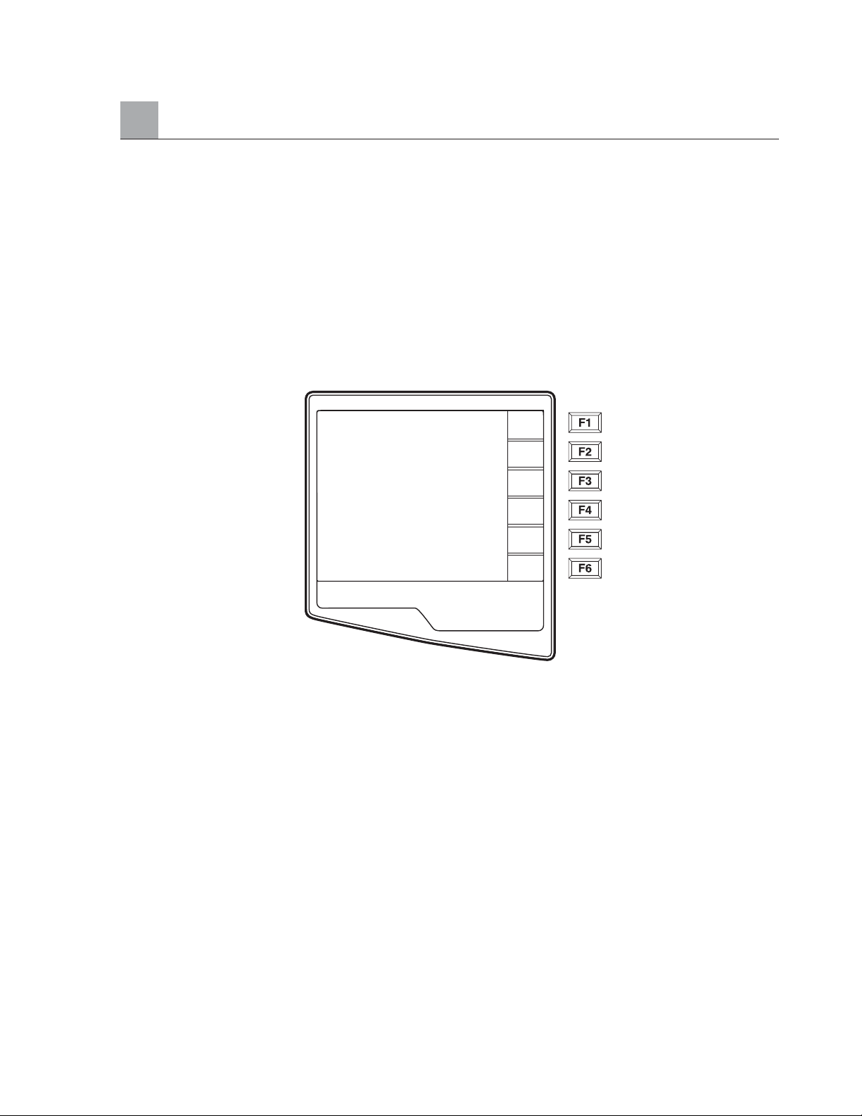
To access the patient demographic data entry menu, press ID (F1) from the Real-Time ECG View. The patient
demographic labels available are determined by the ID format selected in the configuration settings. The short
ID format is pictured below:
NOTE: If a Custom ID has been downloaded to the ELI 250, Custom demographic labels
will appear as it was designed in your E-Scribe data management system. See Appendix A
for more details.
Patient demographic entry can be completed manually for a new patient or automatically from an existing
patient record in the directory. Manually enter the patient demographics and use Enter, Ta b or F1 (▲) and
F2 (▼)to move to each data entry field. Skipped fields will appear as a blank field on the header of the
ECG printout.
TIP: Type the letter F to change the gender to female or type the letter M to change the
gender to male.
To automatically populate the demographics of an existing patient, select the desired patient from the directory
by selecting Direc (F5) from the ID screen.
SECTION 4
4-3
▲
Last Name:
1st Name:
ID:
DOB: – –/– –/– – – –
Age:
Sex: Male
▼
▲
Req
Direc
Done
Page 50
SECTION 4
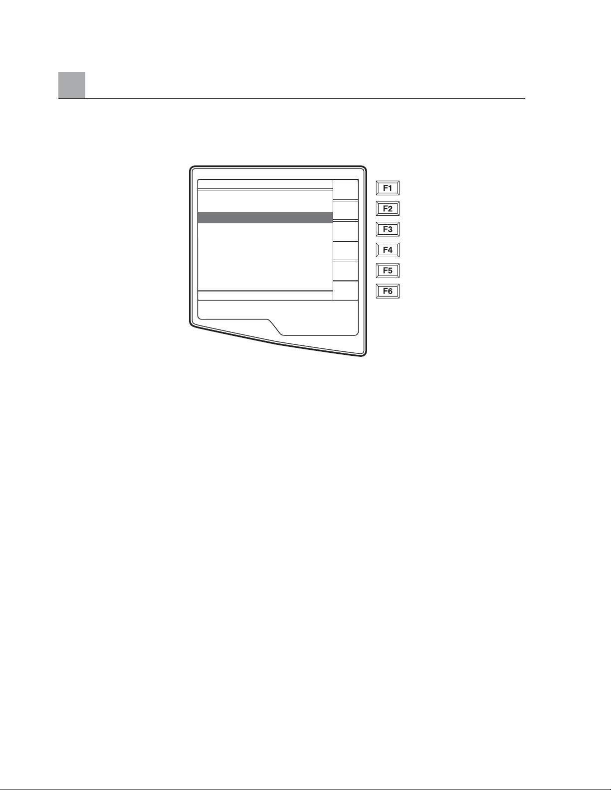
The patient directory (sorted by name) is pictured below.
Use ▼/▲ (F1) to navigate down the Directory list and Shift ▼/▲ (F1) to move up the list. Similarly, use
▼▼/▲▲ (F2) to page down and Shift ▼▼/▲▲ (F2) to page up through the directory. To quickly select a
patient name, use the keyboard to enter the first letter of the last name. Once the desired name is highlighted,
press Selec (F3) and the patient ID screen will return with all demographic fields populated. Return to RealTime ECG View by selecting Done (F6).
TIP: Automatically populating demographic fields via the directory is only possible when the
ID formats match.
If the Auto-Fill ID is enabled in the configuration, the system will automatically populate the demographic
fields in the ID screen. When the patient ID field is manually populated and followed either by selecting
enter or F2 (▼) the system automatically scans the patient directory and if records with the exact ID are
found, the existing data is used to fill some of the demographic fields. The auto-fill feature is designed to
only automatically populate last name, first name, date of birth, age and gender. If no matching records are
found, a brief message is displayed and the user must manually enter the patient’s demographics.
NOTE: In order to avoid the use of incorrect data, the Auto-Fill ID feature is only possible
when the ID formats are the same between records.
When time is of the essence or if patient demographics are not available, ID information can be added to
the ECG after it has been acquired via the patient directory. Acquiring an emergency or unidentified ECG
is explained below.
In addition to the Short, Standard or Long patient ID format, the ELI 250 also supports a Custom ID format.
The custom format, which is designed in the E-Scribe data management system, can be downloaded to the
ELI 250. Additional information about the Custom ID is described in Appendix A.
4-4
012345 13:45 Nov 21 2001
Adams P X
Anderson P X
Davis P
Johnson P
Jones P
Smith P X
Stevens P X
Stevens P X
Stevens P X
D
▼/▲
▼▼/▲▲
Selec
Delet
More
Exit
Page 51

ECG Acquisition, Printing, Storage
Acquisition
When a patient is connected to the electrocardiograph, the ELI 250 is continuously collecting and
processing the ECG data; therefore, you should first instruct the patient to relax in a recumbent position
to ensure that the ECG is free from noise and artifact due to patient activity before you press the Auto
ECG or Auto RHY key.
To acquire an emergency ECG or unidentified ECG for a new patient press the Auto ECG key . The
Real-Time ECG View is replaced with the patient ID menu. Select Enter or Done (F6) and the ECG is
acquired. “Collecting 10 seconds of data” is displayed on the top of the LCD and “captured, analyzed,
formatted” is displayed on the bottom of the LCD. The Real-Time ECG View is then replaced with the
Acquired ECG View. To add patient demographics, select the record from the directory and select ID (F1).
When workflow permits patient demographic entry prior to acquisition, connect the patient to the ELI 250
and enter the patient identification information as explained above. After you complete the last data entry
field select Done (F6) to return to the Real-Time ECG View.
Examine the display for artifact (noise), or baseline drift. Re-prep and replace electrodes if necessary to obtain
satisfactory waveforms. (See Patient Preparation, in Section 2). If a lead fail condition exists square waves
appear on the display for that lead and the lead in fault displays in the upper-left corner of the screen (one
at a time). This is to alert the operator of a lead fail condition. When the problem is corrected, the ELI 250
waits for 10 seconds of good data before analyzing the ECG. Please refer to the following troubleshooting
guide based on Einthoven’s Triangle:
SECTION 4
4-5
Artifact Check Electrode
Lead II and III artifact Poor LL electrode
Lead I and II artifact Poor RA electrode
Lead I and III artifact Poor LA electrode
V Leads Re-prep site &
replace electrode
A
RA
I
II III
LL
L
Page 52
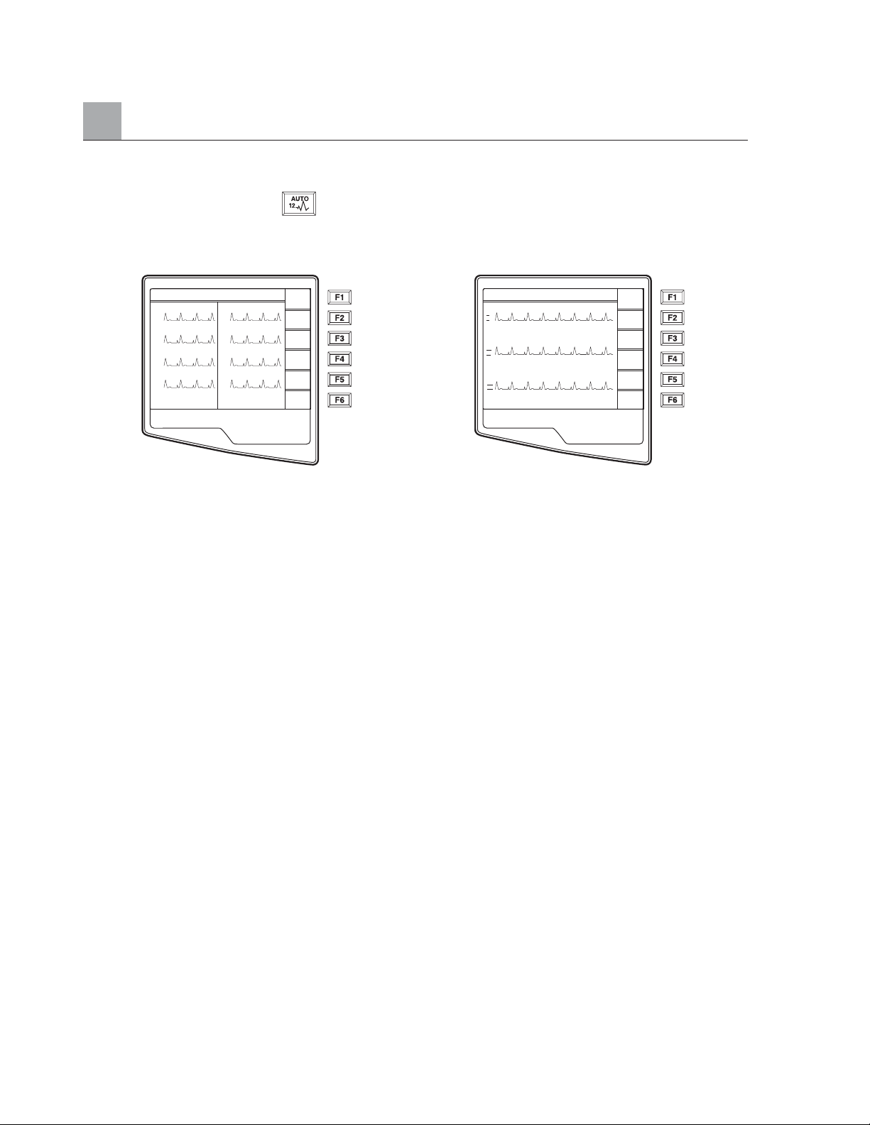
SECTION 4
Finally, select the Auto ECG key . The Real-Time ECG View is then replaced with the Acquired ECG
View. The default Real-Time ECG View (as pictured below) is not available in the Acquired ECG View for
navigation purposes.
Real-Time ECG View Acquired ECG View
NOTE: New softkey labels are available in the Acquired ECG View.
NOTE: Functions are not available during acquisition.
Printing
If the auto-print configuration option is enabled, an ECG is printed following acquisition. Regardless of
the auto-print configuration setting, a manual printout is possible from the Acquired ECG View by
selecting Print (F4).
Toggle through the available Acquired ECG View waveform formats by selecting Leads (F2). A preview of
the full 10-seconds of ECG waveform is available. The first 5 seconds of waveforms are displayed (page 1 / 2 is
displayed in the upper right corner) and by selecting Page (F3), the last 5 seconds of waveform are displayed
(page 2 / 2 is displayed in the upper right corner). If the auto-print configuration option is disabled, the
10-second preview assists in ensuring a quality ECG acquisition prior to printing. When you acquire an ECG,
the cardiograph captures the previous 10 seconds. The relationship between the display and the printout is the
same – what is displayed in the ECG Acquisition View is what will be printed.
4-6
HR 60 25mm/s 10mm/uV 150 Hz
I
II
VI
V2
10: 36: 20
V3
V4
V5
V6
ID
Leads
Speed
Gain
Filt
More
HR 60 25mm/s 10mm/uV 150 Hz
I
1mV
II
1mV
III
1mV
10: 36: 20
Ready to Print
1/2
Leads
Page
Print
More
Done
Page 53
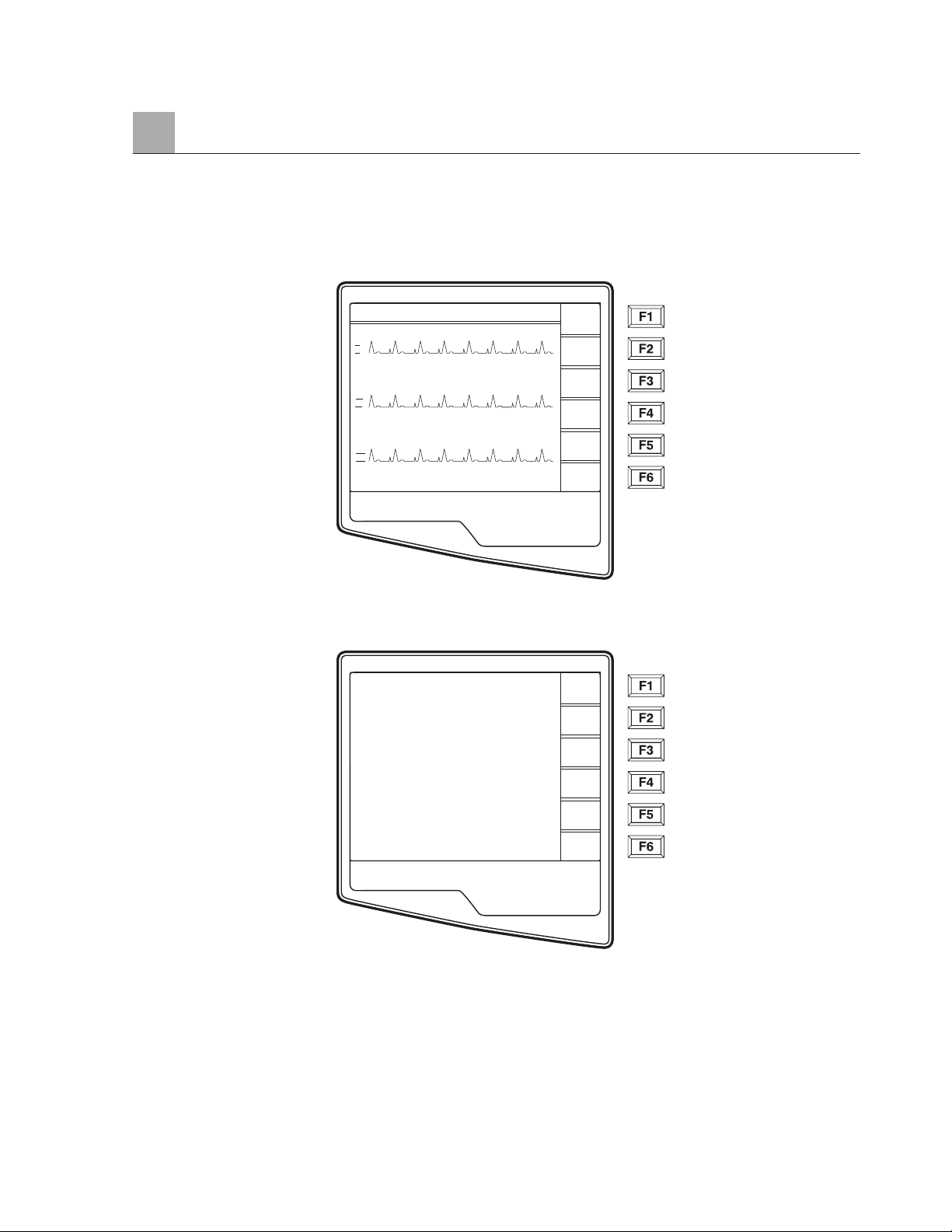
In order to change the speed, gain, filter, or printout format in the Acquired ECG View, select More (F5). The
function key labels change as follows:
To manipulate the print format of the acquired ECG, regardless of the plot format configuration setting, select
Fmt (F4). The following function keys become available:
Select the function key corresponding to the desired print format. The Acquired ECG View is then displayed
and to make an ECG printout copy in the new plot format; select Print (F4). Select Done (F6) to return to
the Real-Time ECG View.
SECTION 4
4-7
HR 60 25mm/s 10mm/uV 150 Hz
I
II
III
10: 36: 20
1/2
Speed
Gain
Filt
Fmt
Save
Back
3 + 1
6 Ch
3 + 3
12 Ch
6 + 6
Page 54
SECTION 4
Storage
The ELI 250 manages storage in one of two ways – automatically or manually. When the Auto Save
configuration option is enabled, ECGs are automatically saved upon acquisition and printing. However,
when the Auto Save configuration option is disabled, upon completion of acquisition, a prompt is
presented as follows and saving the ECG record is at the user’s discretion.
NOTE: If Auto Save is enabled, but the ECG is not printed, the user is prompted to save.
TIP: Manual Save is possible by selecting More (F5) and Save (F5) in the Acquired
ECG View.
Acquiring Rhythm Strips
Rhythm strips are printed in the format defined in the configuration (3-channel, 6-channel, or 12-channel).
See section 3 for instructions to configure rhythm leads.
Begin routine rhythm strips by connecting the patient to the ELI 250 and entering the patient identification
information as described in this section. After the last data entry field from the ID menu is completed,
select Done (F6) to return to the Real-Time ECG View. Select the RHY key to begin rhythm printing.
NOTE: Rhythm printouts are only possible from the Real-Time ECG View.
NOTE: Rhythm acquisitions are only printed and not stored in the electrocardiograph.
4-8
Save
Save ECG?
Delet
Page 55
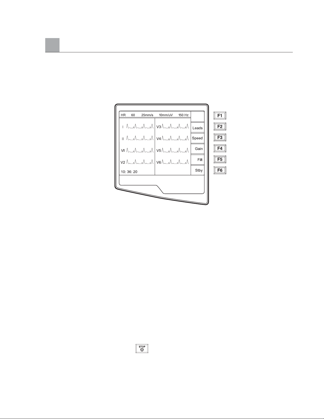
The Rhythm Activity Screen appears as soon as the writer begins printing the rhythm strip. Notice, the
waveform display format is similar to the Real-Time ECG Screen; however, new functions keys are
available during rhythm printing.
In addition to manipulating SPEED, GAIN, FILTER during rhythm printing, the user may also toggle different
lead groups. When the default rhythm format is set to either 3-channel or 6-channel, you may change lead
groups during printing by selecting LEADS (F2). The change in lead groups is apparent on the printout whereas
the waveform display will remain in the default display of 2.5 seconds of leads I, II and V1-V6.
During 3-channel rhythm printing, the available lead groups are:
1. Default (user-selected in configuration)
2. I-II-III
3. aVR, aVL, aVF
4. V1-V2-V3
5. V4-V5-V6
During 6-channel rhythm printing, the available lead groups are:
1. Default (user-selected in configuration)
2. I-II-III-aVR-aVL-aVF
3. V1-V2-V3-V4-V5-V6
During 12-channel rhythm printing, switching lead groups is not available.
During rhythm printing, you may place the writer in standby mode, STBY (F6). To continue rhythm printing
for the same patient, without advancing to a new page, select CONT (F6).
To stop the rhythm printing, press Stop and the writer will automatically form feed in preparation for a
new patient’s rhythm recording or ECG.
SECTION 4
4-9
Page 56
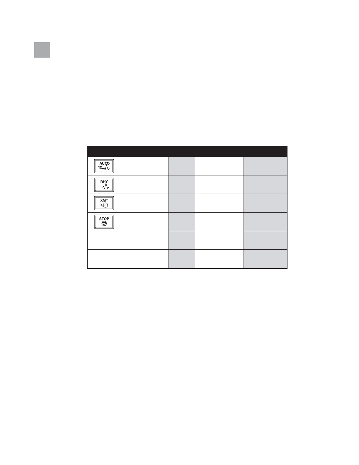
Optional Barcode Scanner
Mortara’s optional barcode scanner is purchased separately. By connecting the barcode scanner to the
electrocardiograph’s RS232 (serial port) all aspects of acquiring an ECG are automated for speed and
accuracy of alpha-numeric entry, functions and feature processes.
In order to map the function and feature keys of the electrocardiograph to a desired barcode font, the
following values and/or symbols must be available:
NOTE: the ELI software will ignore Enter (carriage return) as part of a barcode; please
use F2 (\) instead.
Please reference the Barcode Scanner User Manual for instructions for set-up and use.
SECTION 4
4-10
Feature Keys Value Function Keys Symbol
ECG Acquisition 2 F1 [
Rhythm Printing 3 F2 \
Transmitting 4 F3 ]
Stop 5 F4 _(underscore)
F5 {
F6 }
Page 57
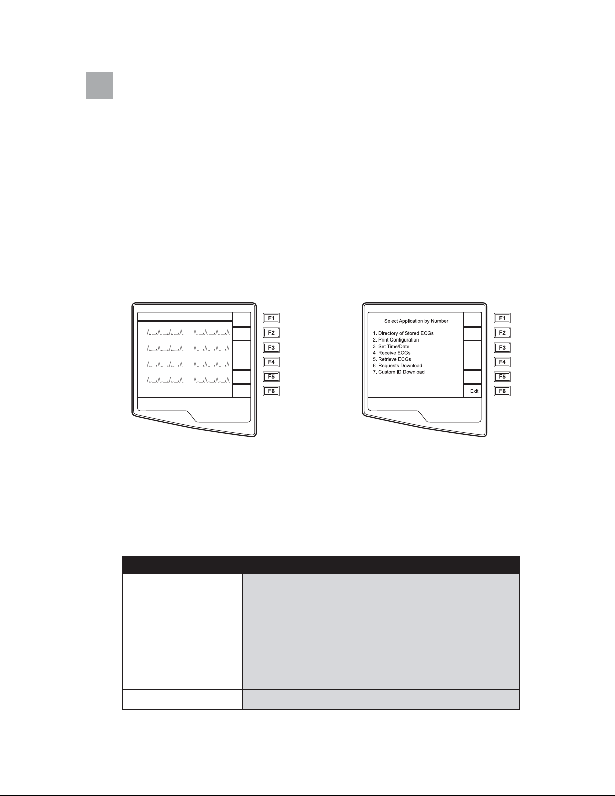
Chapter Purpose
This chapter is intended to provide the user with:
• Summary of the Special Functions
• Patient Directory & Directory Maintenance
• Configuration Printouts
• Set Time & Date
Application Menu
The ELI 250 offers several special functions available through the Application menu. Select More (F6) from
the Real Time ECG View and the Application Menu is displayed.
Real Time ECG View Application Menu
NOTE: Function Keys activate the LCD label adjacent to each function key. If the label is
blank, the adjacent function key is deactivated.
TIP: Select Applications by using the numeric data entry keys.
The following chart summarizes the application functions available. Descriptions of the Applications are
detailed later in this section, following the summary chart.
*Appendix A details the ELI 250 connectivity options.
SPECIAL FUNCTIONS
SECTION 5
5-1
Application Definition
Directory of Stored ECGs Patient list of ECGs stored in the internal memory
Print Configuration Printout of the configuration settings
Set Time/Date Current date and time; LCD Contrast
Receive ECGs* Receive ECGs from another electrocardiograph – See Appendix A
Retrieve ECGs* Retrieve ECGs from the E-Scribe – See Appendix A
Requests Download* “Patient List” from E-Scribe – See Appendix A
Custom ID Download* Custom-designed patient demographic format – See Appendix A
HR 60 25mm/s 10mm/uV 150 Hz
I
II
VI
V2
10: 36: 20
V3
V4
V5
V6
ID
Leads
Speed
Gain
Filt
More
Page 58
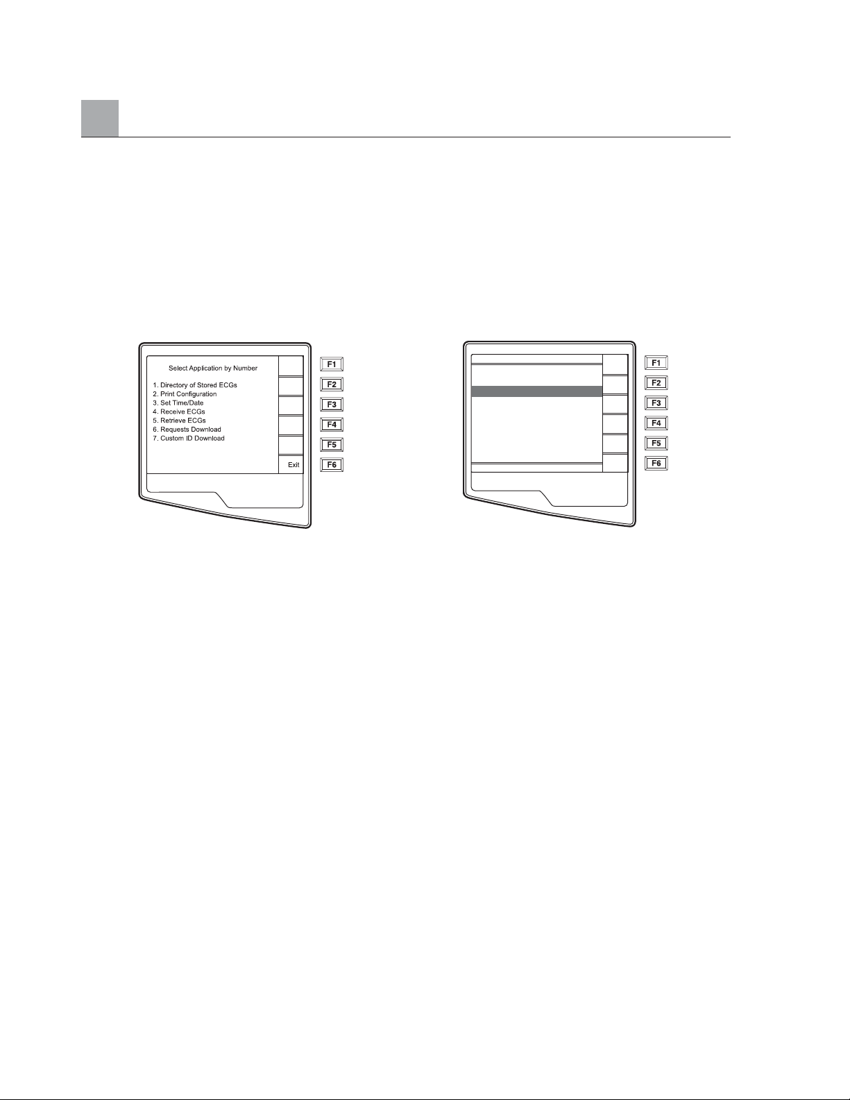
SECTION 5
Patient Directory
The standard patient directory saves up to 60 ECGs depending on the storage space required for individual
record. The optional expanded memory permits up to 150 ECGs. The heart rate, storage sensitivity, and signal
quality determine the ECG file size and ultimately how much memory is needed to store each record.
To access the directory of stored ECGs, select number 1 from the Application menu and the patient directory
list is displayed.
Application Menu Patient Directory
(sorted by name)
NOTE: In the patient directory list, “P” represents the record has been printed, “X” represents
the record has a delete status, and “T” represents the record has been transmitted.
Management of the ECG record is performed within the directory of stored ECGs. The desired record must
be highlighted in order to view, print, edit or add demographics, and to change delete status.
Use ▼/▲ (F1) to navigate down the directory list and Shift ▼/▲ (F1) to move up the list. Similarly, use
▼▼/▲▲ (F2) to page down and Shift ▼▼/▲▲ (F2) to page up through the directory. To quickly find and
select a patient name, use the keyboard to enter the first letter(s) of the last name. The letters will be
displayed on the lower left corner of the LCD and the desired name will automatically be highlighted.
An ECG may be listed in the directory but have a “deleted status” (indicated by “X”). The directory saves
those records that have been marked for deletion in the event that you may want to recover the ECG at a
later time. All stored ECGs will remain in the directory until it becomes full, at this time, the ELI 250 will
automatically remove a record, based on its size, in order to make room for the new ECG. Only those records
that have been marked for deletion will be removed. Records are automatically marked for deletion based on
the Delete Rule in the configuration. To manually mark an ECG record for deletion, press Delet (F4) and an
“X” will appear. To remove the delete status, select F4 again.
NOTE: Only when the directory becomes full, ECGs that are marked for deletion are
automatically removed from the directory based on their record size to make room
necessary for the new ECG record.
TIP: Use the delete rule in the configuration settings to automatically define the ECG delete
status. (See section 3).
NOTE: Record status symbols: X =deleted, P = printed, T=transmitted. When the directory
is sorted by ID and Date status symbols are displayed on the top row of the LCD. If sorted
by Name, symbols are displayed on the right hand column as pictured below.
5-2
012345 13:45 Nov 21 2001
Adams P X
Anderson P X
Davis P
Johnson P
Jones P
Smith P X
Stevens P X
Stevens P X
Stevens P X
D
▼/▲
▼▼/▲▲
Selec
Delet
More
Exit
Page 59
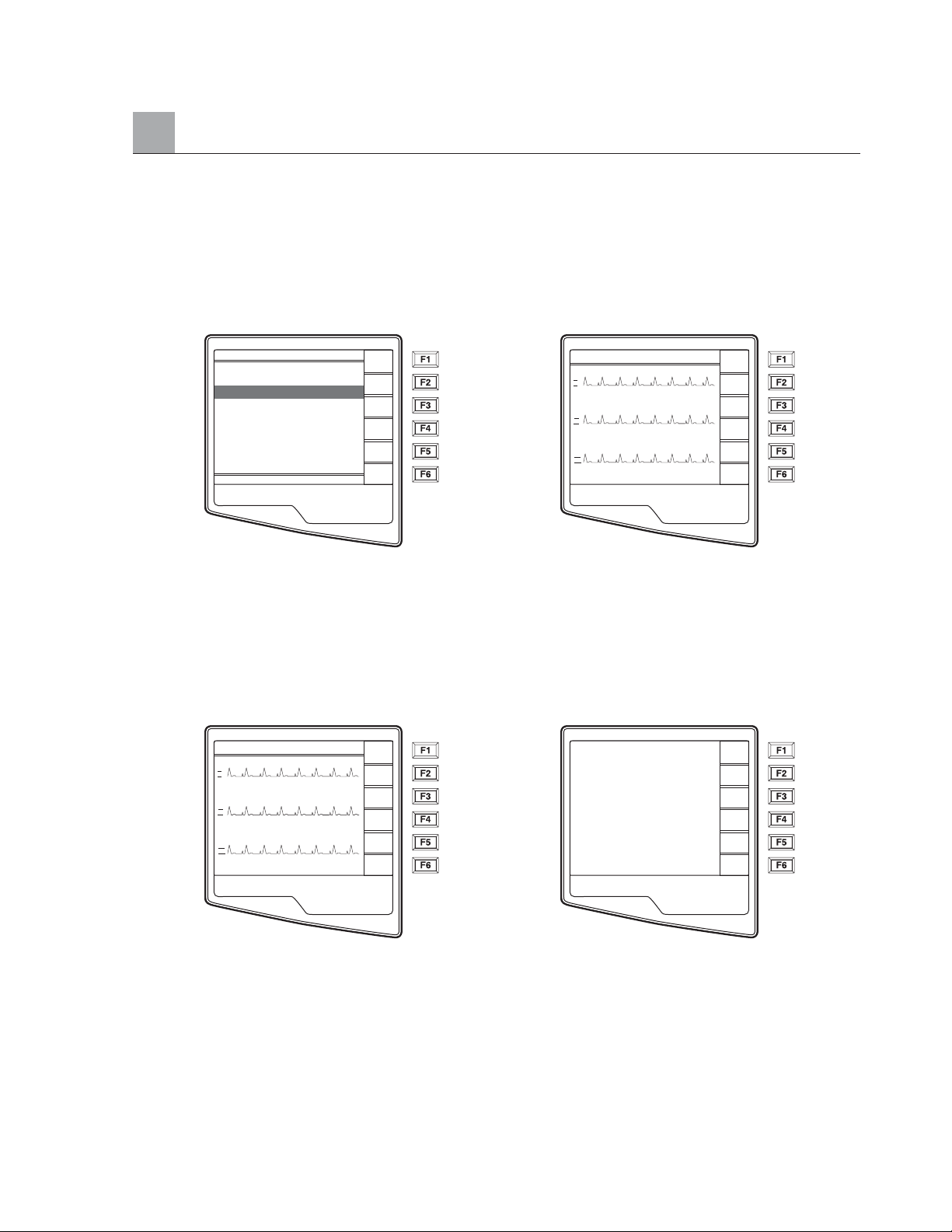
To view a specific ECG record, highlight the desired name from the directory list and press Selec (F3). The
selected patient’s ECG is presented in Acquired ECG View with the same functions available as previously
described. To access the patient demographics screen, select ID (F1) to change or add patient information.
Toggle through the available Acquired ECG View waveform formats by selecting Leads (F2) and Page (F3).
To make an additional copy of the ECG, select Print (F4).
Patient Directory Acquired ECG View
(sorted by name)
NOTE: To return to the Patient Directory, select Done (F6) from the Acquired ECG View.
In order to change the speed, gain, filter, or printout format in the Acquired ECG View, select More (F5).
The function key labels change as depicted below. To manipulate the print format of the acquired ECG,
regardless of the plot format configuration setting, select Fmt (F4). Select Done (F6) to return to the
Acquired ECG View.
More (F5) from Acquired ECG View Plot Format (F4)
SECTION 5
5-3
012345 13:45 Nov 21 2001
Adams P X
Anderson P X
Davis P
Johnson P
Jones P
Smith P X
Stevens P X
Stevens P X
Stevens P X
D
▼/▲
▼▼/▲▲
Selec
Delet
More
Exit
HR 60 25mm/s 10mm/uV 150 Hz
I
1mV
II
1mV
III
1mV
10: 36: 20
Ready to Print
ID
1/2
Leads
Page
Print
More
Done
HR 60 25mm/s 10mm/uV 150 Hz
I
II
III
10: 36: 20
Speed
1/2
Gain
Filt
Fmt
Back
3 + 1
6 Ch
3 + 3
12 Ch
6 + 6
Page 60
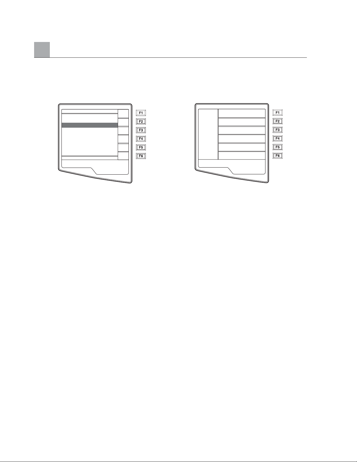
SECTION 5
The directory of stored ECGs is easily sorted either by Name, ID, or Date. To sort the patient records, select
More (F5) from the patient list.
Patient Directory Directory Organization
(sorted by name)
Select F1 to sort the directory by patient name (ID, time & date are displayed on the top row)
Select F2 to sort the directory by patient ID (name is displayed on the top row)
Select F3 to sort the directory by acquisition date (name is displayed on the top row)
To make a printout of the patient directory, select Print Directory (F4). The directory lists stored ECGs based
on how you have the directory sorted. The printout indicates if the ECGs have been printed, marked deleted,
or transmitted (with an “X” in the appropriate column). Exit (F6) to return to the Patient Directory.
5-4
012345 13:45 Nov 21 2001
Adams P X
Anderson P X
Davis P
Johnson P
Jones P
Smith P X
Stevens P X
Stevens P X
Stevens P X
D
▼/▲
▼▼/▲▲
Selec
Delet
More
Exit
Sort Requests by Name
Sort Requests by ID
Sort Requests by Date
Print Requests
Exit
Page 61
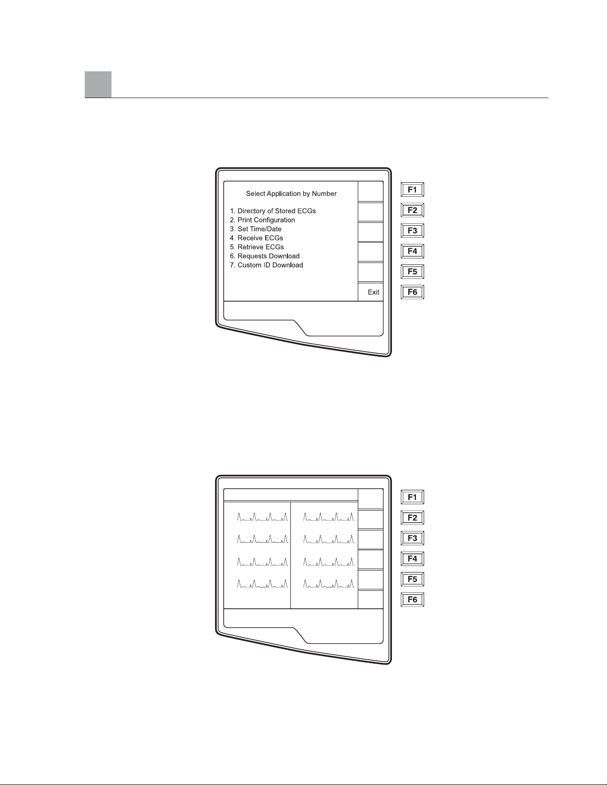
Print Configuration
In order to verify the cardiograph’s configuration settings, a printout of the unit’s configuration is possible
from the Application menu by selecting Print Configuration (2). The configuration printout obtains every
configuration setting for the specific cardiograph, the firmware version, the cart number of the unit, and the
date and time that the configuration printout occurred.
Set Time/Date and LCD Contrast
➊ Select More (F6) from the Real Time ECG View.
SECTION 5
5-5
HR 60 25mm/s 10mm/uV 150 Hz
I
II
VI
V2
10: 36: 20
V3
V4
V5
V6
ID
Leads
Speed
Gain
Filt
More
Page 62
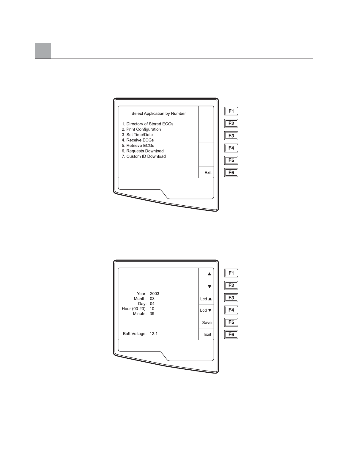
SECTION 5
❷ Select Set Time/Date (number 3) from the Application menu.
❸ The preprogrammed date and time is displayed for the ELI 250. To make changes, type in the
desired date and time values (using a 24-hour clock) in the same format as displayed. Use (F1)
and (F2) to move back and forth through each row.
TIP: Use the BACKSPACE key to erase entry errors.
❹ LCD contrast can be adjusted by selecting Lcd (F3) or Lcd (F4).
➎ Select Save (F5) to save changes before exiting.
➏ Select Exit (F6) to return to Real-Time ECG View. If you do not save before selecting exit, any
changes you have made to the time/date will be lost.
TIP: The battery voltage value is monitored at the bottom of this screen.
5-6
➔
Page 63
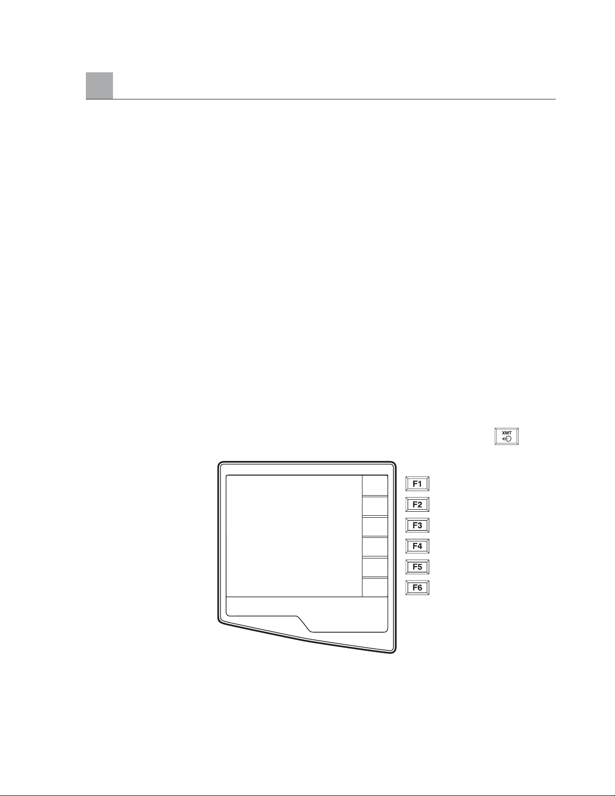
Chapter Purpose
This chapter is intended to provide the user with:
•Transmitting Records
• Direct
• Modem
• WLAN
• LAN
• ECG Receiving instructions
• ECG Retrieving instructions
• Requests Download
•Custom ID
Transmitting Records
You may transmit ECGs from the ELI 250 to another Mortara Instrument electrocardiograph, to an E-Scribe
Data Management System, or to ELI LINK using a direct connection, an optional factory installed internal
modem, or network connection.
Before transmitting ECGs certain configuration options must be set depending upon the optional
transmission media being used (see Section 3).
NOTE: Telephone transmission is available with modem option only.
To transmit records (either to another cardiograph, to ELI LINK or to E-Scribe), select XMT .The
following screen is displayed:
To batch transmit of all records in the directory, select F1 (Batch). If a batch transmission is selected, only
those records, which have not been previously transmitted or marked deleted, will be transmitted.
An ECG may be listed in the directory but have a “deleted status” (indicated by “X”). The directory saves
those records that have been marked for deletion in the event that you may want to recover the ECG at a
later time. All stored ECGs will remain in the directory until it becomes full, at this time, the ELI 250 will
automatically remove a record, based on its size, in order to make room for the new ECG. Only those records
APPENDIX A ELI 250 CONNECTIVITY
APPENDIX A
A-1
Batch
Selec
Exit
Page 64
APPENDIX A
that have been marked for deletion will be removed. Records are automatically marked for deletion based on
the Delete Rule configuration. To manually mark an ECG record for deletion, press Delet (F4) and an “X”
will appear in the far right hand column of the directory and to remove the delete status, select F4 again.
To transmit one ECG, select F2 (Selec) to choose a record from the patient directory.
Use ▼/▲ (F1) to navigate down the directory list and Shift ▼/▲ (F1) to move up the list. Similarly, use
▼▼/▲▲ (F2) to page down and Shift ▼▼/▲▲ (F2) to page up through the directory. To quickly find and
select a patient name, use the keyboard to enter the first letter(s) of the last name. The letters will be
displayed on the lower left corner of the LCD and the desired name will automatically be highlighted.
When the desired record is highlighted, use F3 (XMT) to transmit the individual ECG.
The following screen appears during a batch transmission or for a single record transmission:
After the transmission of your record(s), the Real-Time ECG View is displayed.
A-2
Transmission Status
Connected
Bytes Transmitted XXXXX
XX ECG (s) Transmitted
Page 65
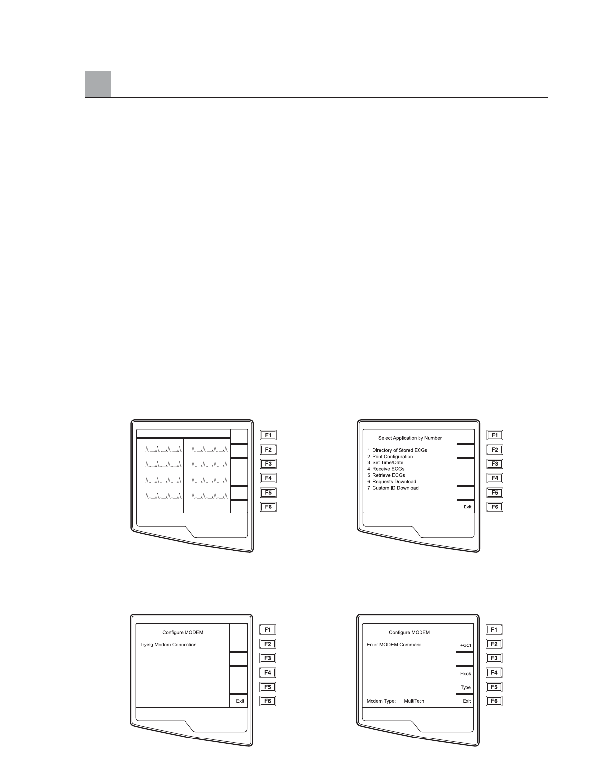
Direct Connection
For a direct connection hookup, set the Default XMT media to RS232 from Configuration page 6 (see section 3
of this manual). Connect the ELI 250 to another Mortara Instrument electrocardiograph, to the E-Scribe, or to
ELI LINK with a direct connect serial cable.
In the configuration setting, select matching baud rates for both units. Use 38400 bps for a direct connection
to E-Scribe.
Modem Transmission
For a modem transmission, set the Default XMT media to Modem from Configuration page 6 (see section 3
of this manual). Connect the ELI 250 to a standard telephone jack with the provided phone line cable. Plug
the cable into the telephone jack located on the back of the cardiograph and the other end into a telephone
wall jack. Confirm telephone number in the configuration settings (see Section 3 of this manual).
Modem Initialization
The modem initialization string is country specific. At the time of production, the modem initialization string is
configured for the country of purchase. However, if the unit is relocated to a different country, the modem
initialization string will need to be modified.
From the Real Time ECG View, select F6 (More) to display the Application Menu.
Real Time ECG View Application Menu
From the Application Menu, simultaneously press ALT+SHIFT+M to access the modem initialization string.
The following screens appear:
Approximately 30 second delay
APPENDIX A
A-3
HR 60 25mm/s 10mm/uV 150 Hz
I
II
VI
V2
10: 36: 20
V3
V4
V5
V6
ID
Leads
Speed
Gain
Filt
More
Page 66
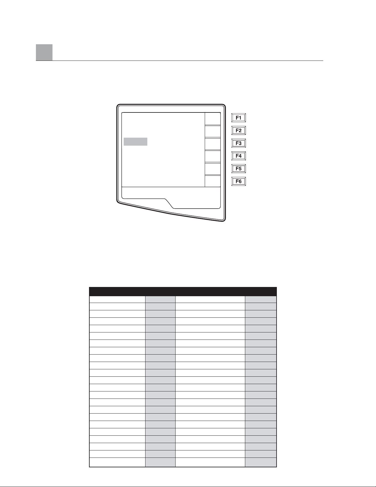
APPENDIX A
From the Configure Modem screen, select F2 (+GCI=) to populate the prefix “AT+GCI” of the modem command.
TIP: “AT+GCI” will be highlighted – cursor is not present – use keypad to enter country code.
The type of modem installed in your cardiograph is displayed at the bottom of the Configure Modem
screen. Depending upon the type of modem, use the corresponding list below to enter your country code.
Select F1 (Send) to change your country code. “Sending . . .” and “Command stored” will be displayed.
Select F6 (Exit) to return to the Application Menu.
XIRCOM MODEM COUNTRY CODE LIST:
A-4
Country Code Country Code
Argentina 07 Liechtenstein 68
Australia 09 Luxembourg 69
Austria 0A Japan 00
Barbados 0E Korea 61
Belgium 0F Malaysia 6C
Brazil 16 Mexico 73
Canada 20 Netherlands 7B
Czech Republic 2E New Zealand 7E
China 26 Norway 82
Denmark 31 Poland 8A
Finland 3C Portugal 8B
France 3D Russia B8
Germany 04 South Africa 9F
Greece 46 Singapore 9C
Guam 48 Slovak Republic FC
Hungary 51 Spain A0
Hong Kong 50 Sweden A5
Iceland 52 Switzerland A6
India 53 Taiwan FE
Indonesia 54 Thailand A9
Ireland 57 United Kingdom B4
Israel 58 United States B5
Italy 59 Venezuela BB
Configure MODEM
Enter MODEM Command:
AT + GCI = XX
Modem Type: MultiTech
Send
Hook
Type
Exit
Page 67
Blind Dialing for Xircom Modems
Using the ATX3 command may support specific countries where the “wait for dial tone” often causes
dialing/telephone issues. Following the steps outlined above, access the Configure Modem Screen. Using
the keypad, enter ATX3. Select F1 (Send). The following status messages will be displayed:
“Sending…”
“Command Stored”
“Reading Status, please wait…..”
The country code string will be displayed.
Press F6 (Exit)
MulitTech MODEM COUNTRY CODE LIST:
APPENDIX A
A-5
Country Code Country Code
Argentina 07 Italy FD
Australia 09 Japan 00
Austria FD Korea B5
Belgium FD Liechtenstein FD
Canada B5 Luxembourg FD
China B5 Mexico B5
Cyprus FD Netherlands FD
Czech Republic FD New Zealand 7E
Denmark FD Norway FD
Finland FD Philippines B5
France FD Portugal FD
Germany FD Slovak Republic FD
Greece FD Spain FD
Hong Kong 99 Sweden FD
Hungary FD Switzerland FD
Iceland FD Taiwan FE
Indonesia 99 United Kingdom FD
Ireland FD United States B5
Page 68

External Modem
Before using the external modem, modem command(s) must be entered and two configuration settings must
be defined. In the configuration, select “external modem” for the XMT Media and set the baud rate to 57600.
From the modem configuration screen, as described above, enter and send the initialization command as
AT&FEQX4&K.
If a country specific code is necessary the following list of countries require “%T19,0,XX” to be added to the
modem initialization string. Where “XX” is replaced by the country code number in the following table:
EXTERNAL MODEM COUNTRY CODE LIST:
APPENDIX A
A-6
Country Code Country Code
Afghanistan 34 Canary Islands 34
Albania 34 Cape Verde 34
Algeria 34 Cayman Islands 34
American Samoa 34 Central African Republic 34
Andorra 34 Chad 34
Angola 34 Chile 34
Anguilla 34 China 34
Antigua and Barbuda
34 Colombia 34
Argentina 34 Congo 34
Armenia 34 Congo, The Democratic 34
Republic of the
Aruba 34 Cook Islands 34
Australia 1 Costa Rica 34
Austria 34 Côte D'Ivoire 34
Azerbaijan 34 Croatia 34
Bahamas 34 Cyprus 34
Bahrain 34 Czech Republic 25
Bangladesh 34 Denmark 34
Barbados 34 Djibouti 34
Belarus 34 Dominica 34
Belgium 34 Dominican Republic 34
Belize 34 East Timor 34
Benin 34 Ecuador 34
Bermuda 34 Egypt 34
Bhutan 34 El Salvador 34
Bolivia 34 Equatorial Guinea 34
Bosnia and 34 Estonia 34
Herzegovina
Botswana 34 Ethiopia 34
Brazil 34 Faero Islands 34
Brunei Darussalam 34 Fiji 34
Bulgaria 34 Finland 34
Burkina Faso 34 France 34
Burundi 34 French Guiana 34
Cambodia 34 French Polynesia 34
Cameroon 34 Gabon 34
Page 69
APPENDIX A
A-7
Country Code Country Code
Canada 34 Gambia 34
Georgia 34 Korea, Republic of 30
(South Korea)
Germany 34 Kyrgyzstan 34
Ghana 34 Lao People's 34
Democratic Republic
Gibraltar 34 Latvia 34
Greece 34 Lebanon 34
Greenland 34 Liberia 34
Grenada 34 Libya 34
Guadeloupe 34 Liechtenstein 34
Guam 34 Lithuania 34
Guatemala 34 Luxembourg 34
Guernsey, C.I. 34 Macau 34
Guinea 34 Macedonia, The Former 34
Yugoslav Republic of
Guinea-Bissau 34 Madagascar 34
Guyana 34 Malawi 34
Haiti 34 Malaysia 30
Holy See 34 Maldives 34
(Vatican City State)
Honduras 34 Mali 34
Hong Kong 30 Malta 34
Hungary 30 Martinique 34
Iceland 34 Mauritania 34
India 30 Mauritius 34
Indonesia 30 Mayotte 34
Iran 34 Mexico 34
Iraq 34 Moldova, Republic of 34
Ireland 34 Monaco 34
Isle of Man 34 Mongolia 34
Israel ,30 Montserrat 34
Italy 34 Morocco 34
Jamaica 34 Mozambique 34
Japan 10 Namibia 34
Jersey C.I. 34 Nauru 34
Jordan 34 Nepal 34
Kazakhstan 34 Netherlands 34
Kenya 34 Netherlands Antilles 34
Kiribati 34 New Caledonia 34
Kuwait 34 New Zealand 9
Nicaragua 34
Niger 34 Swaziland 34
Nigeria 34 Sweden 34
Norway 34 Switzerland 34
Oman 34 Syrian Arab Republic 34
Pakistan 34 Taiwan 34
Palestine Territory, 34 Tajikistan 34
Occupied
Page 70
APPENDIX A
A-8
Country Code Country Code
Panama 34 Tanzania, United 34
Republic of
Papua New Guinea 34 Thailand 34
Paraguay 34 Thaiti 34
Peru 34 Togo 34
Philippines 30 Tonga 34
Poland 30 Trinidad and Tobago 34
Portugal 34 Tunisia 34
Puerto Rico 34 Turkey 34
Qatar 34 Turkmenistan 34
Reunion 34 Turks and Caicos Islands 34
Romania 34 Uganda 34
Russian Federation 34 Ukraine 34
Rwanda 34 United Arab Emirates 34
Saint Kitts and Nevis 34 United Kingdom 34
Saint Lucia 34 Uruguay 34
Saint Vincent and 34 USA 34
the Grenadines
Samoa 34 Uzbekistan 34
Saudi Arabia 34 Vanuatu 34
Senegal 34 Venezuela 34
Seychelles 34 Viet Nam 30
Sierra Leone 34 Virgin Islands, British 34
Singapore 30 Virgin Islands, U.S. 34
Slovakia 34 Yemen 34
Slovenia 30 Yugoslavia 34
Solomon Islands 34 Zambia 34
South Africa 35 Zimbabwe 34
Spain 34
Sri Lanka 34
Sudan 34
Surinam 34
Page 71

WLAN Transmission
For a WLAN transmission, set the Default XMT media to WLAN from Configuration page 6 (see section 3
of this manual). It is necessary that the IT Manager of your facility configure the wireless access point(s) and
E-Scribe workstation. Also, it is required that your IT Manager set the ELI 250 WLAN configuration values.
Refer to section 3 for more information on WLAN configuration setup. The ELI 250 can be configured for
DHCP (Dynamic Host Communication Protocol) and for WEP (Wired Equivalent Privacy) security.
NOTE: Environmental conditions may affect the reliability of WLAN transmissions.
If DHCP is set to NO, your wireless access point will have a static network setting and the following
parameters must be configured in the ELI 250:
IP Address
Def Gateway
Sub Net Mask
If DHCP is set to YES, your wireless access point will have an automatic network setting and IP Address,
Def Gateway and Sub Net Mask do not need to be configured.
In either DHCP setting, the following wireless network parameters must be configured in the ELI 250 by your
IT Manager:
Host IP
Port Number
SSID
Channel Number
NOTE: Addresses are always entered as 4 sets of 3 digits; therefore, an address of 192.168.0.7
must be entered on the ELI 250 as 192.168.000.007.
If WEP Security is disabled on your access point then set Security (WEP) to NO. If WEP Security is enabled
on your access point then the following wireless network parameters must be configured in the ELI 250 by the
IT Manager:
Security (WEP): YES
WEP Key
WEP Key ID
NOTE: The range for the WEP Key on the ELI 250 is 0-3. If the range on your access
point is 1-4, then 0 at the ELI 250 maps to 1 on the access point; 1 at the ELI 250 maps to 2
on the access point, etc.
APPENDIX A
A-9
Page 72
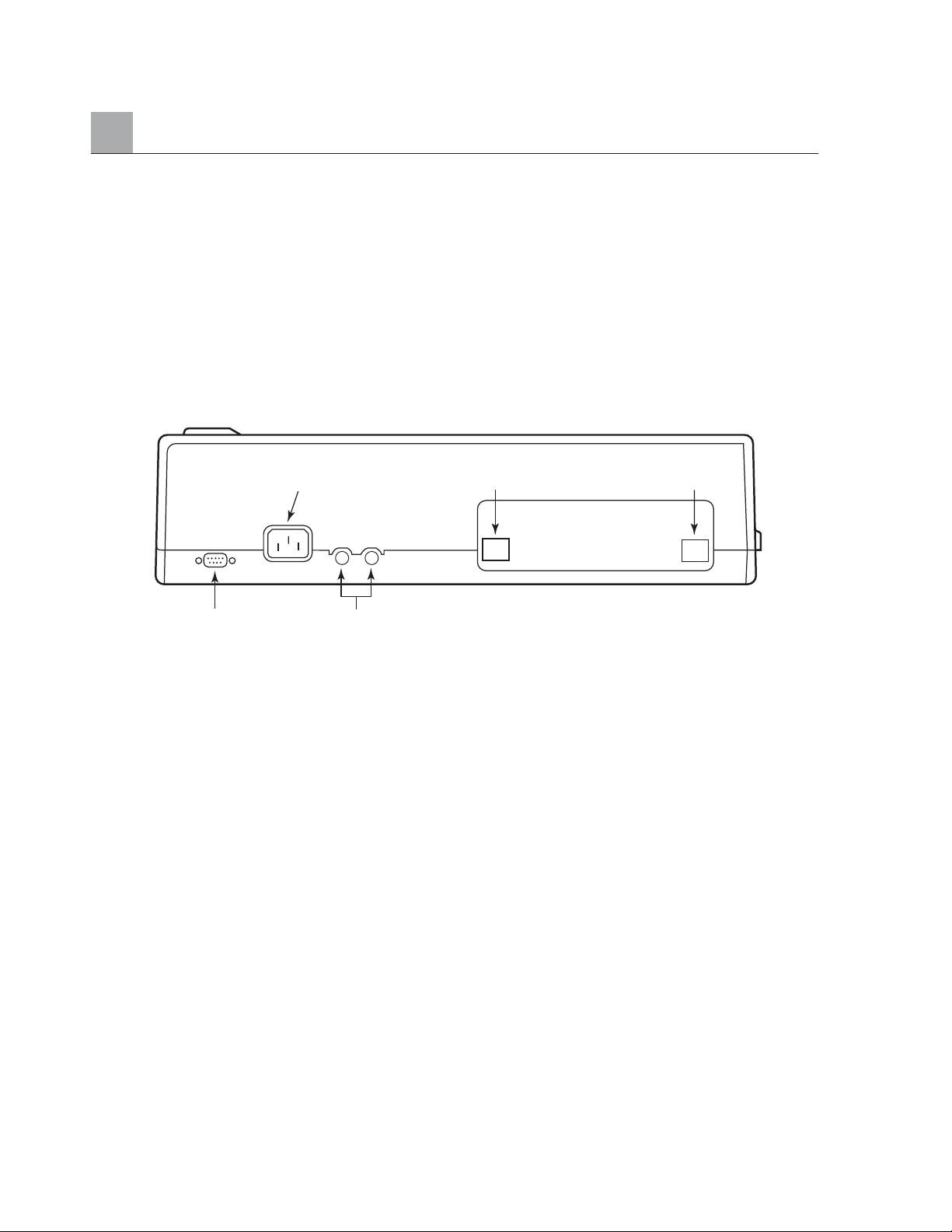
APPENDIX A
LAN Transmission
For a LAN transmission, set the Default XMT media to LAN from Configuration page 6 (see section 3 of this
manual). It is necessary that the IT Manager of your facility set the ELI 250 LAN configuration values. Refer
to section 3 for more information on LAN configuration setup.
NOTE: Addresses are always entered as 4 sets of 3 digits; therefore, an address of 192.168.0.7
must be entered on the ELI 250 as 192.168.000.007.
Connect the Ethernet cable to the LAN connection at the rear of the ELI 250, as pictured below.
CAUTION: Possible damage to the cardiograph may occur if telephone cable is connected to
the LAN connector.
Ethernet Status LEDs
At the external LAN interface connector, the user is presented with two LEDs (Light Emitting Diodes). The
two status indicator LEDs provide signals for “link status” and “packet transmit/receive”. As the external
connector is viewed from the outside, rear of the ELI 250, the left LED remains illuminated when the network
link is detected. The ELI 250 LAN will support signaling rates of 10 and 100 MBPS. The right LED flashes
when a transmit or receive packet occurs or any traffic on the network is detected.
A-10
AC (Powercord) Connector
AC FusesSerial Connector
RJ45
LAN
(Optional)
Modem Connector
(Optional)
Page 73
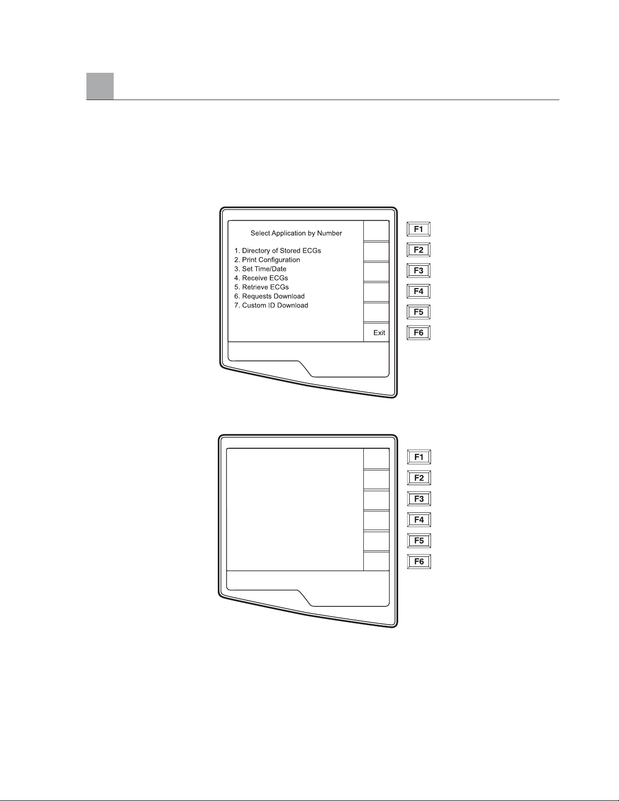
Receive ECGs
To receive ECGs from another Mortara Instrument electrocardiograph (using either a telephone or a direct
connection), select Receive ECGs (4) from the Application Menu.
The LCD displays the following message:
When the LCD displays the above message, the unit is ready to receive the ECGs from the transmitting
electrocardiograph. Follow the instructions on transmitting records as described in this section. The receiving
unit only acts as a printer. Received ECGs will not be viewed or stored. To terminate the receiving mode,
press the STOP key.
NOTE: The ELI 250 will receive records from Mortara model cardiographs except for
Mortara’s Portrait. The Mortara model cardiographs (ELI 100, ELI 200, Landscape, and
Portrait) will not receive the ELI 250 records.
APPENDIX A
A-11
Press STOP to terminate
Page 74
APPENDIX A
A-12
Retrieve ECGs
It is possible to retrieve ECGs from the E-Scribe Data Management System using any of the connectivity
options. Before attempting to retrieve ECGs, please configure the Default XMT Media, the telephone
number (if using modem transmission) and the site number (see Section 3). Select Retrieve ECGs (5)
from the Application Menu. The following screen appears:
NOTE: The ID field defaults the last acquired ECG
ECGs are retrieved by ID number. Enter the desired ID and select F1. E-Scribe transmits the most recent
ECG with the specified ID number (or the configured number of ECGs retrieved– refer to Section 3). The
ELI 250 prints the retrieved ECG(s) and returns to the Real-Time ECG View. Viewing and storing retrieved
ECGs is not possible.
Transmission Status
Enter Desired ID
Retrv
Exit
Page 75
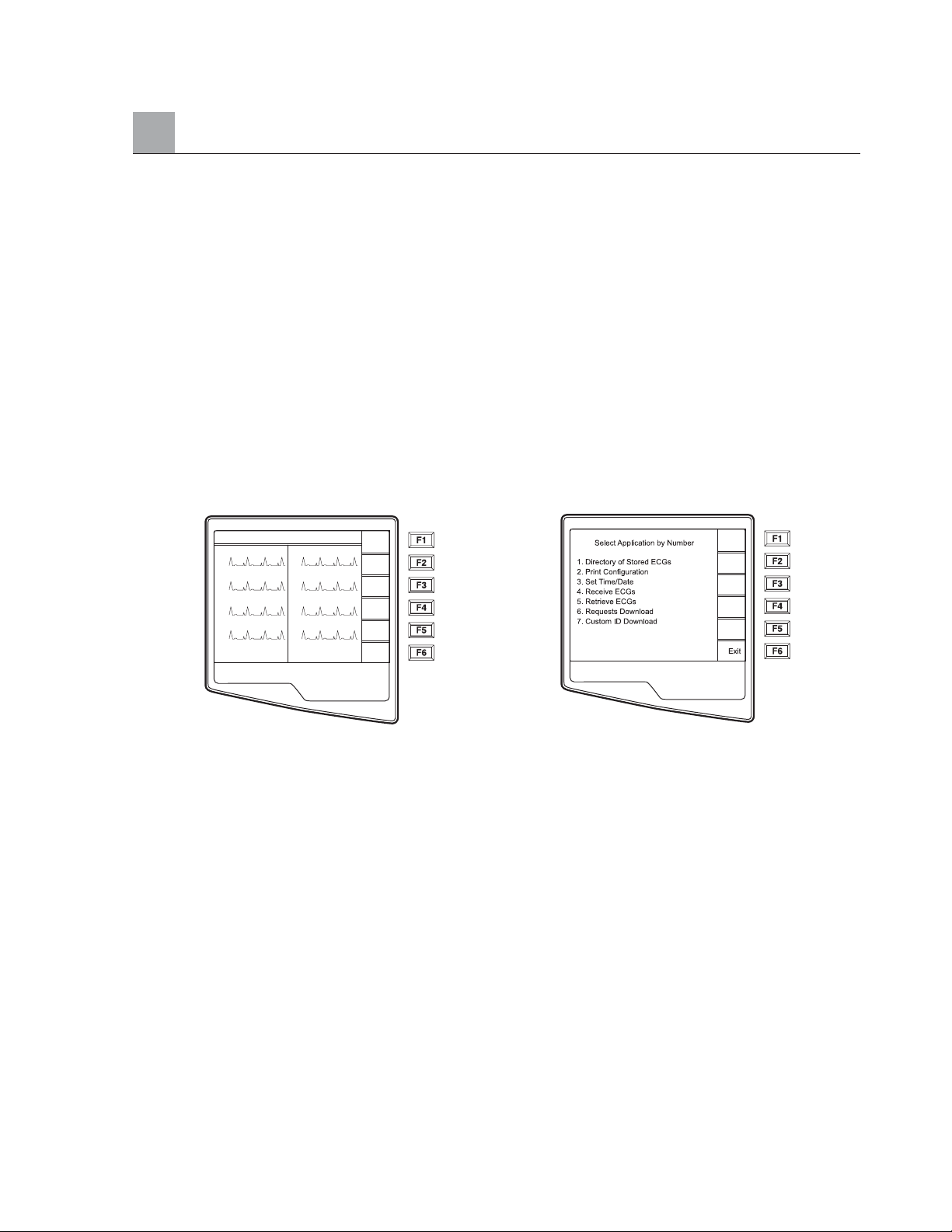
APPENDIX A
A-13
Requests Download
The ELI 250 can download and process a patient request list from the E-Scribe, which identifies the ECGs
(or ECG orders) needed for particular patients. Request Codes are designed in your E-Scribe Data
Management System, which contain the particular patients who require ECGs. The technician at the cardiograph
selects the desired Request Code (e.g. a code specific to a department or floor) and does not have to enter the
demographic information for the patients belonging to the Request Code. Once downloaded, the patient list
for each Request Code is stored in the cardiograph as the Request List (similar to the patient directory). As
with the other forms of ECG data transmission, you can use either the optional modem or a direct connection.
Follow the hookup instructions under Transmitting Records in this section.
NOTE: A Custom ID must be downloaded before downloading the Requests (please
reference the E-Scribe Operator Manual and Custom ID Format of this Section).
From the Real Time ECG View, select F6 (More) to display the Application Menu.
Real Time ECG View Application Menu
HR 60 25mm/s 10mm/uV 150 Hz
I
II
VI
V2
10: 36: 20
V3
V4
V5
V6
ID
Leads
Speed
Gain
Filt
More
Page 76
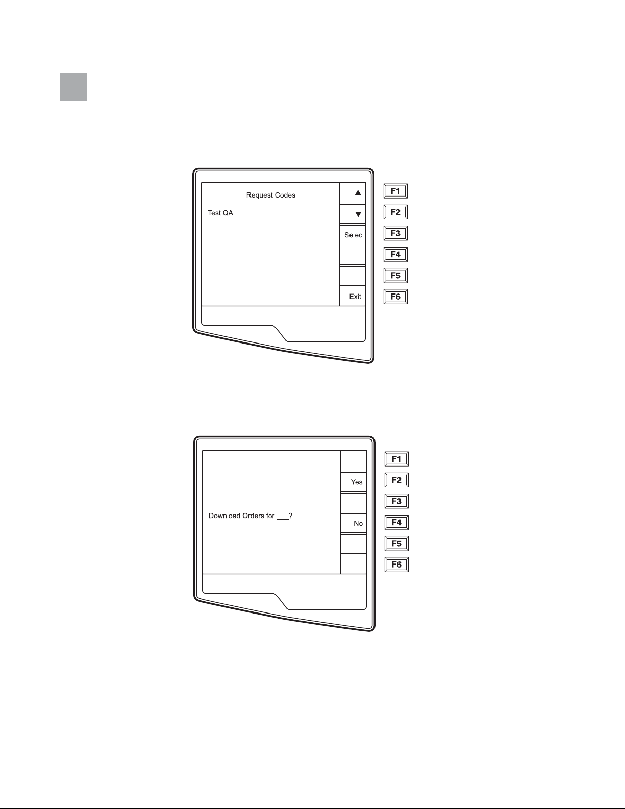
APPENDIX A
A-14
From the Application Menu, select number 6 (Requests Download) and the following screen is displayed:
The Request Code(s) is (are) displayed. Use F1 (F1) and (F2) to scroll through the available Request Codes.
Request Codes are only available if a Custom ID has been downloaded. Once you find the desired Request
Code, Select F3 (Selec) to select the desired Request Code. Confirm or deny your download by selecting
F2 or F3 from the following screen:
NOTE: A Custom ID must be downloaded before downloading the Requests.
Page 77
APPENDIX A
A-15
“Transmission Status” will be displayed for approximately 10 seconds followed by “Dialing: telephone
number”, “Waiting for Response”, and “Connected”. Once connected, the following screen indicates the
number of Requests received (patients) for the Request Code. This only appears briefly and returns to
the Real Time ECG View.
Transmission Status
Transmission Status
Requests Received: 5
Page 78
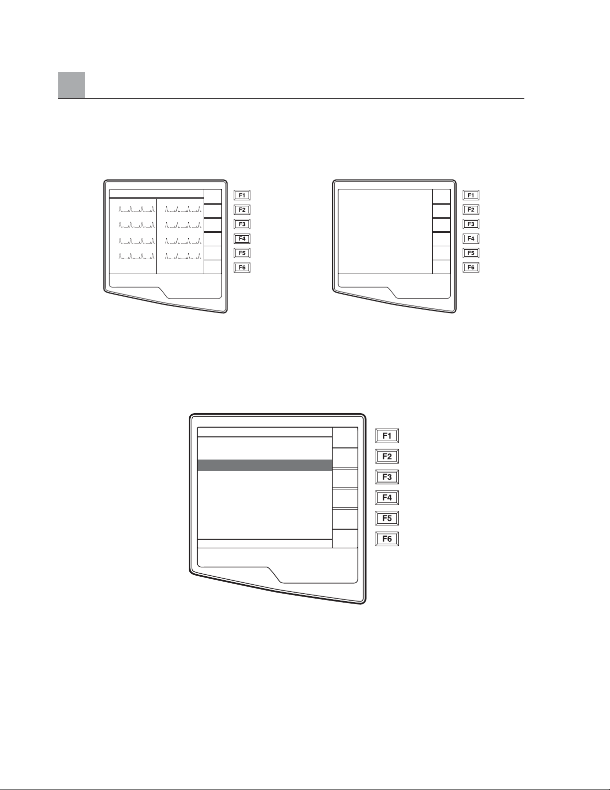
APPENDIX A
A-16
When the Request List has been downloaded, you may select the patients who need ECGs. Select ID (F1)
from the Real-Time ECG View.
Real Time ECG View Patient ID
Patient Request List
Select Req (F4) from the Patient ID screen and the Patient Request List is displayed. The Patient Request
List is comparable to the Patient Directory in looks and in practice. The Patient Request List (sorted by name)
is pictured below.
Similar to the Directory of stored ECGs, the Patient Request List is easily sorted either by Name, ID, or Date.
To sort the Requests, select More (F5) from the Patient Request List.
HR 60 25mm/s 10mm/uV 150 Hz
I
II
VI
V2
10: 36: 20
V3
V4
V5
V6
Leads
Speed
Gain
More
ID
Last Name:
1st Name:
ID:
Filt
DOB: – –/– –/– – – –
Age:
Sex: Male
▲
▼
▲
Req
Direc
Done
Adams
Anderson
Davis
Johnson
Jones
Smith
Stevens
Stevens
Stevens
▼/▲
▼▼/▲▲
Selec
Delet
More
Exit
Page 79
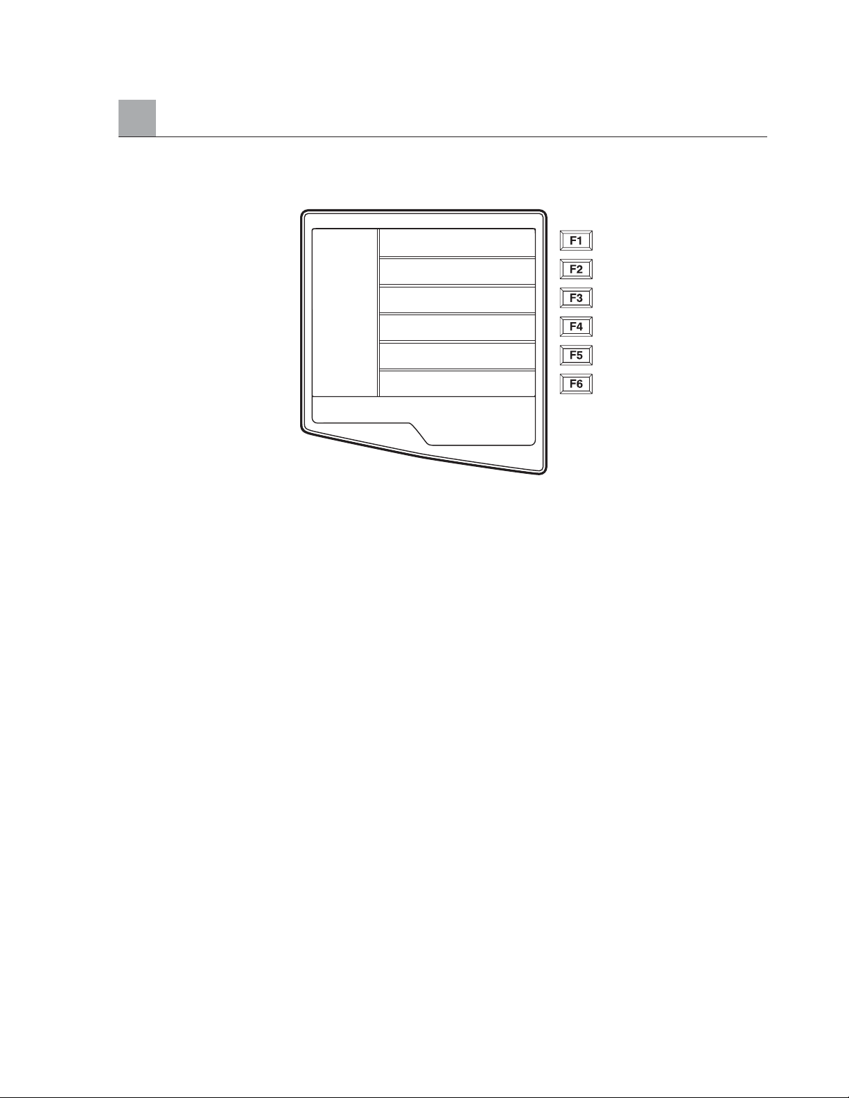
APPENDIX A
A-17
Select F1 to sort the requests by patient name (ID, time & date are displayed on the top row)
Select F2 to sort the requests by patient ID (name is displayed on the top row)
Select F3 to sort the requests by acquisition date (name is displayed on the top row)
To make a printout of the Patient Requests List, select Print Requests (F4). Exit (F6) to return to the Patient
Requests List.
Use ▼/▲ (F1) to navigate down the Patient Request List and Shift ▼/▲ (F1) to move up the list. Similarly,
use ▼▼/▲▲ (F2) to page down and Shift ▼▼/▲▲ (F2) to page up through the Request List. To quickly
select a patient name, use the keyboard to enter the first letter of the last name. Once the desired name is
highlighted, press Selec (F3) and the patient ID screen will return with all demographic fields populated.
Return to Real-Time ECG View by selecting Done (F6). Once the ECG is acquired, the patient will be
automatically removed from the Patient Request List and the ECG will be stored in the Patient Directory.
Sort Requests by Name
Sort Requests by ID
Sort Requests by Date
Print Requests
Exit
Page 80
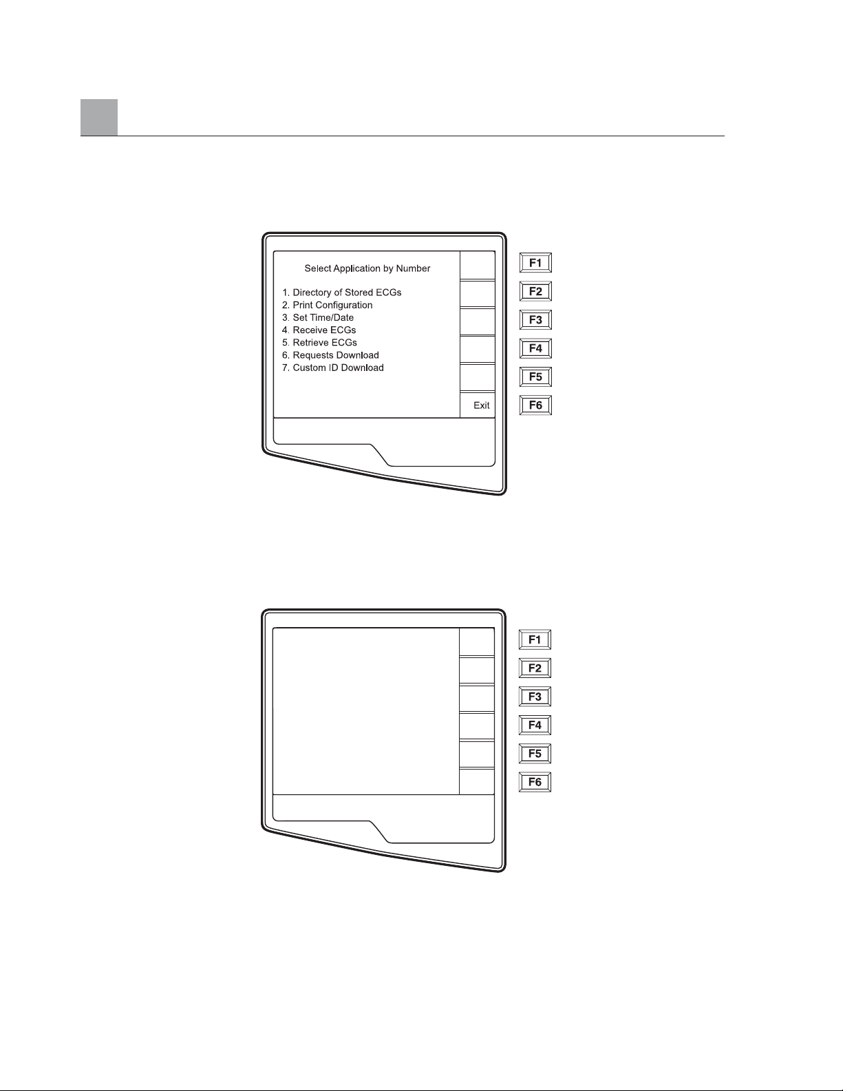
APPENDIX A
A-18
Custom ID Download
Custom ID formats are uniquely defined by your facility’s needs. This customized ECG header information
is designed in the Mortara E-Scribe data management system and downloaded to the ELI 250 as the Group
Name either by serial connection (direct) or modem transmission.
Select Custom ID Download (7) from the Application menu and the following screen appears:
Transmission Status
Page 81
APPENDIX A
A-19
“Transmission Status” will remain visible for approximately 10 seconds before the following screen appears:
“Waiting for Response”, “Connected”, and “Custom ID downloaded” will be displayed before returning to the
Real-Time ECG View, which indicates the Custom ID download is complete. The new Custom ID becomes
the customized header format for all future ECGs until you select a different ID format in the configuration
settings. You may alter the ID format configuration to Short, Standard, Long or Custom based on your patient
demographic entry needs. The Custom ID is only deleted upon downloading a new Custom ID or on the rare
occasion of downloading software – it will not be lost due to power loss or switching to a different ID format.
TIP: Upon Custom ID download, the ID format will assume the group name as designed in
the E-Scribe.
NOTE: A Custom ID must be downloaded before downloading the Request Codes
(please reference the E-Scribe Operator Manual).
NOTE: The site number must be configured in the cardiograph and recognized as an
established, valid site number at the E-Scribe before downloading the custom ID.
TIP: Confirm the baud rate in the configuration settings before downloading the custom ID
from the E-Scribe.
Transmission Status
Dialing OW14143549999
Page 82

APPENDIX A
A-20
Page 83
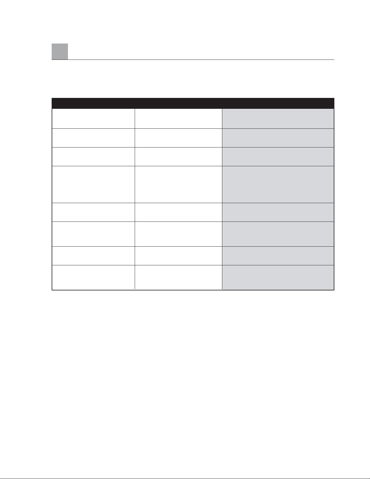
Troubleshooting Chart
APPENDIX B MAINTENANCE AND TROUBLESHOOTING
APPENDIX B
B-1
LCD Message Problem Correction
BATTERY LOW Unable to acquire ECG Charge the battery with AC power.
or unable to print.
CONNECTION FAILED Unable to transmit or receive ECGs. Check for correct baud rate, phone number,
and cable connections or site number.
NO ANSWER Unable to transmit ECG. Check for correct phone number. Insure
modems and E-SCRIBE are online.
LEADS OFF OR ONE OR Lead fail. Indication of
MORE OF THE FOLLOWING: RL/RA/LA/LL/V1/V2/V3/V4/V5/V6.
RA, LA, LL, Check limb leads.
V1, V2, V3, V4, V5, V6
Correct faulty lead(s).
TRANSMIT FAILED Unable to transmit ECG. Check phone line. Insure site number
is valid. Try again.
UNABLE TO SAVE ECG No available memory. Press stop to continue. Transmit or mark
records for deletion in the directory.
ECG data too noisy to store. Correct noise and try aquisition/storage again.
LEAD FAULT, NO Lead fail or noisy ECG data. Correct faulty lead or noise.
ECG CAPTURE
PAPER QUEUE FAULT Unable to print. Add paper; manually advance page evenly
passed closure point of writer and close
writer cover and press STOP.
Page 84

APPENDIX B
Inspection and Cleaning
If the hospital or institution fails to implement a satisfactory cleaning and inspection schedule for this
equipment, it may result in equipment failure and health hazards.
NOTE: Only qualified service personnel should repair or replace ELI 250 parts.
Inspecting the ELI 250
Inspect the equipment for the following conditions on a regular basis:
• Examine patient cable, power cable and other accessory cables for obvious damage
(e.g. torn insulation, broken connectors, etc.). Replace cables as necessary.
• No bent prongs or pins on the plugs and connectors. Check the fit of cables with connectors
on the ELI 250 to ensure proper fit.
• All cords and connectors are securely seated in their corresponding connections.
• Examine the equipment for missing screws, cracks or broken areas that might allow unintended
access to internal electronics areas.
Cleaning the ELI 250
Disconnect the power source. Clean the exterior surface of the unit with a damp cloth using a solution of mild
dishwashing detergent diluted in water. After washing, thoroughly dry off the unit with a clean, soft cloth or
paper towel.
Cleaning Print-Head
NOTE: Do not let soap or water come into contact with the writer, plugs, jacks or vents.
Test Operation
After cleaning and inspecting the ELI 250 proper operation of the unit may be confirmed by using an ECG
simulator to acquire and print a standard 12-lead ECG of known amplitude. Printing should be dark and
even across the page. There should be no evidence of print-head dot failure (e.g. breaks in printing forming
horizontal streaks). Paper motion should be smooth and consistent during printing. Waveforms should appear
normal, with proper amplitude, and without distortion or excessive noise. Paper should stop with perforations
near the tear-bar (indicating proper cue sensor operation).
B-2
Page 85

Recommendations to Biomedical Staff
Following any service to the ELI 250 or when non-compliant operation is suspected, Mortara Instrument, Inc.
recommends the following procedures:
• Confirm proper operation
• Perform testing to ensure continued electrical safety of the device
(use IEC 60601-1 or ANSI/AAMI ES1 methods and limits)
• Patient leakage current
• Chassis leakage current
• Earth leakage current
• Dielectric strength (mains and patient circuits)
Cleaning the Patient Cable
Patient cables should be kept clean using a damp cloth of lukewarm soapy water or a neutral cleaner. To
disinfect the patient cable, use a damp cloth of chemical disinfectants containing ethanol (70% - 80%),
propanol (70% - 80%) or aldehydes (2% - 4%).
WARNING: Do not attempt to clean/disinfect the ELI 250 or patient cable(s) by submerging
into a liquid, autoclaving, or steam cleaning. Never expose cables to strong ultra-violet radiation.
Battery Maintenance
The ELI 250 houses an internal sealed lead-acid battery. When installed, the battery has a shelf life
of approximately six months, without recharging. If the battery has been stored for a long period in a
discharged state; it may not be able to regain its capacity even if it is recharged.
For information about replacing the battery, please refer to the ELI 250 service manual.
Mortara Instrument, Inc. recommends that the ELI 250 be plugged into AC power whenever possible to
maximize battery life and for the user to develop a habit of recharging the battery before the unit indicates
“low battery” condition. (That is, reduce depth of discharge.) Battery life varies by how the battery is
maintained and how much it is used. For improved battery life, keep the cardiograph plugged in when not
in use.
The sealed lead-acid battery will provide optimum life when the unit is fully charged after each use. The
ELI 250 will charge a depleted battery to 90% of its capacity in approximately 8 hours or less. To recharge
a battery from its lowest level, 30 hours of recharging without operation will be necessary.
APPENDIX B
B-3
Page 86

APPENDIX B
B-4
Page 87

GLOSSARY
GLOSSARY
G-1
TERM DEFINITION
Augmented lead (aVL, aVR, aVF) The difference between one site and the average
of the potential of two other sites; unipolar extremity leads.
Baseline drift The QRS complexes are present, but the baseline wanders due to
poor skin/electrode contact and/or patient movement.
Bradycardia A slow heart rate.
Calibration pulse Standardization pulse. A base to compare the relationship of QRS
complexes to one another.
Gain An increase in amount, magnitude or degree.
J point The end of the QRS complex; the point where the QRS ends and
the ST segment begins (QRS offset).
Limb lead Bipolar lead that represents the differences of electrical potential
between two selected sites (leads I, II, III).
Muscle noise Grossly uneven baseline caused by patient body tremor or other
muscle movement. The artifact may be so large that it overtakes
the complex.
Precordial leads (V1-V6) Unipolar chest leads.
Premature atrial complex (PAC) An arrhythmia that has its origin in the atrium.
Premature Ventricular Complex (PVC) An arrhythmia that has its origin in the ventricle.
ST depression The amount of ST deviation below the baseline.
ST elevation The amount of ST deviation above the baseline.
ST level The numerical value of the measured ST segment in microvolts.
ST segment Ventricular repolarization. The end of the S wave (J point) to the
beginning of the T wave.
Tachycardia A rapid heart rate.
Page 88

GLOSSARY
G-2
 Loading...