

Moovo XA User Manual
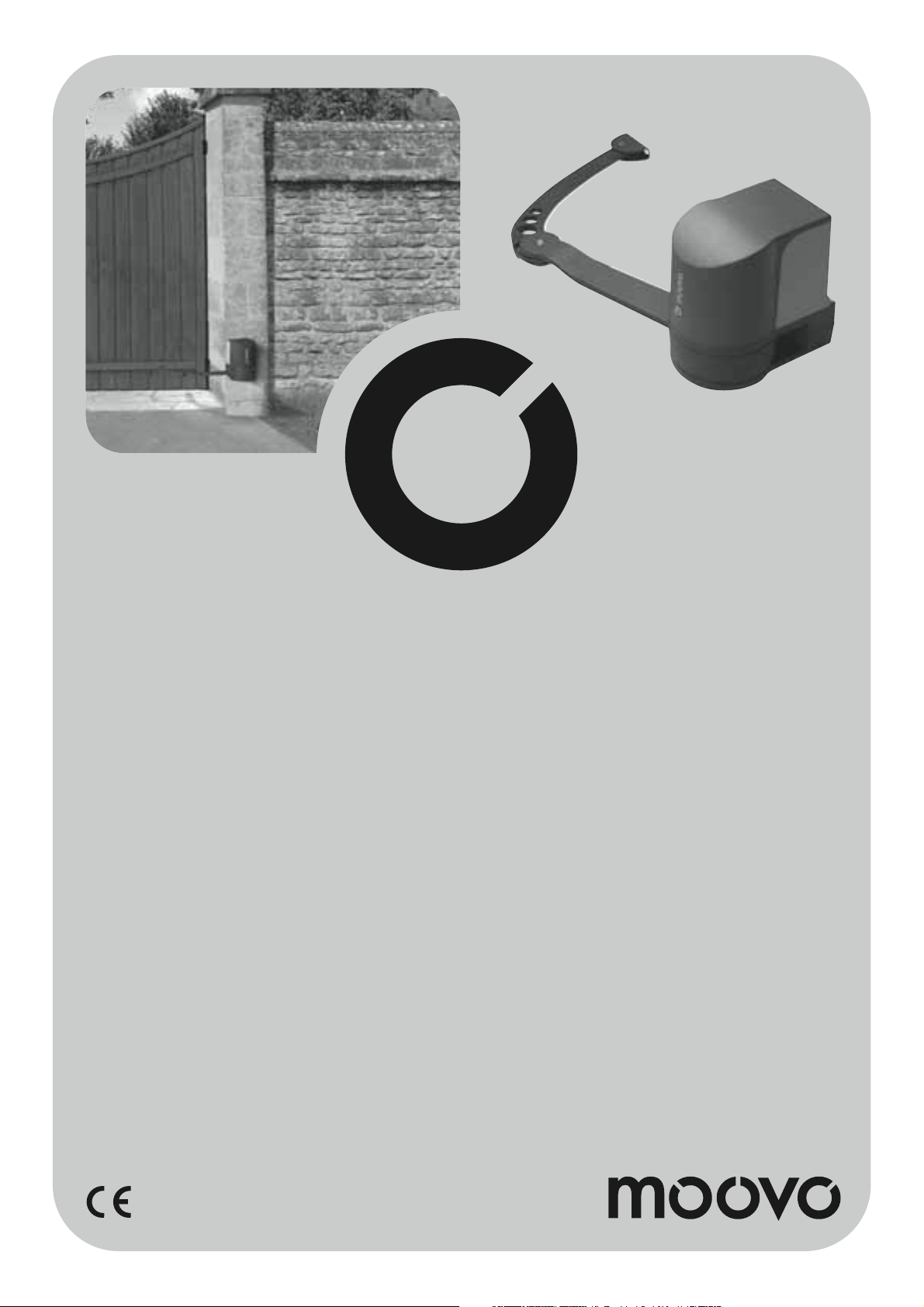
Swing gate opener
XA4
EN Installation and use instruc-
tions and warnings
IT Istruzioni ed avvertenze
per l’installazione e l’uso
FR Instructions et avertisse-
ments pour l’installation et
l’utilisation
ES Instrucciones y adverten-
cias para la instalación y
el uso
DE Anweisungen und Hinweise
für die Installation und die
Bedienung
PL Instrukcje instalacji i
użytkowania i ostrzeżenia
NL Aanwijzingen en aanbeve-
lingen voor installering en
gebruik
Codice: ISTXA432.4865 - Rev. 00 del 08 - 06 - 2007

CONTENTS
GENERAL SAFETY WARNINGS AND PRECAUTIONS
STEP 1
– WORKING IN SAFETY! 4
– Installation warnings 4
KNOWLEDGE OF THE PRODUCT AND PREPARATION
FOR INSTALLATION
STEP 2
2.1 - Product description and intended use 5
2.2 - Components used to set up a complete system 5
STEP 3
Preliminary checks for installation 6
3.1 - Checking suitability of the environment and gate to be automated 6
3.2 - Checking product application limits 6
STEP 4
4.1 - Preliminary set-up work 7
- 4.1.1 - Typical reference system
- 4.1.2 - Establishing positions of components
- 4.1.3 - Establishing the device connection layout
- 4.1.4 - Check all tools required for the work
- 4.1.5 - Complete set-up work
4.2 - Preparing the electrical cables 8
INSTALLATION: COMPONENT ASSEMBLY AND
CONNECTIONS
STEP 5
5.1 - Installing the automation components 10
5.2 - Adjustment of the mechanical limit switch on opening 12
TASKS RESERVED FOR QUALIFIED TECHNICIANS
– Connecting the automation to the electrical mains using a cable other
than the version supplied. 28
– Automation testing and commissioning
– Product disposal 29
TECHNICAL SPECIFICATIONS OF PRODUCT COMPONENTS 30
WHAT TO DO IF ... (Troubleshooting guide) 32
Enclosures: “TECHNICAL DOCUMENTATION” I-VII
7
7
7
8
8
English
STEP 6
– Installation and connections of system devices to the control unit 13
6.1 - Setting the gate leaf opening sequence 14
– Removing the control unit 15
6.2 - Installing and connecting the gearmotor without control unit 16
6.3 - Installing and connecting flashing light mod. MF 17
6.4 - Installing and connecting photocells mod. MP 19
– Selecting operating mode of photocell pair 20
6.5 - Installing and connecting keypad mod. MK 21
6.6 - Installing buffer battery mod. MB 22
POWER SUPPLY CONNECTION
STEP 7 23
INITIAL START-UP AND ELECTRICAL CONNECTION
CHECK
STEP 8 23
PROGRAMMING THE AUTOMATION
STEP 9
9.1 - Memorising devices connected by means of “Bus” cable and leaf travel
limit positions “0” and “1” 24
9.2 - Memorisation of transmitter mod. MT4 24
9.3 - Programming keypad mod. MK 25
ADJUSTMENTS AND OTHER OPTIONAL FUNCTIONS
10 - Automation operation adjustment 26
11 - Memorisation of a new transmitter with control unit “in the vicinity”
procedure. 26
12 - Deleting data from the control unit memory 27
English – 3
SAFETY WARNINGS AND PRECAUTIONS
STEP 1
English
WORKING IN SAFETY!
Please note - These instructions must be followed to guarantee personal safety
Please note – Important safety instructions. Keep for
future reference.
The design and manufacture of the devices making up the product
and the information in this manual fully comply with current standards governing safety. However, incorrect installation or programming may cause serious physical injury to those working on or using
the system. For this reason, during installation, always strictly
observe all instructions in this manual.
If in any doubt regarding installation, do not proceed and contact the
Moovo Technical Assistance for clarifications.
If this is the first time you are setting up an automation for swing
gates or doors, we recommend that you read this entire manual with
care. This is preferable before any work, without any hurry to start
practical tasks.
Also keep product devices on hand while consulting the manual to
enable testing and checking (excluding any programming phases)
with the information provided in the manual.
While reading this manual, take care to observe all instructions
marked with the following symbol:
These symbols indicate subjects that may be the source of potential
hazards and therefore the prescribed operations must be performed
exclusively by qualified and skilled personnel, in observance of
these instructions current safety standards.
Technical documentation. This must be compiled by a professional
installer.
Considering the risk situations that may arise during installation
phases and use of the product, the automation must be installed in
observance of the following warnings:
– never make any modifications to part of the automation other than those
specified in this manual. Operations of this type will lead to malfunctions.
The manufacturer declines all liability for damage caused by makeshift
modifications to the product.
– ensure that parts of the automation cannot come into contact with
water or other liquids. During installation ensure that no liquids penetrate
the gearmotors or other devices present.
– Should this occur, disconnect the power supply immediately and contact a Moovo service centre. Use of the automation in these conditions
constitutes a hazard.
– never place automation components near to sources of heat and never
expose to naked flames. This may damage system components and
cause malfunctions, fire or hazardous situations.
– all operations requiring opening of the protection housings of various
automation components must be performed with the control unit disconnected from the power supply. If the disconnect device is not in a visible
location, affix a notice stating: “WARNING! MAINTENANCE IN
PROGRESS”.
– the product may not be considered an efficient system of protection
against intrusion. If an efficient protection system is required, the automation must be integrated with other devices.
– Connect the control unit to an electric power line equipped with an
earthing system.
– the product may only be used after completing the automation “commissioning” procedure as specified in paragraph
and commissioning”
qualified technicians”.
– The automation component packaging material must be disposed of in
full observance of current local legislation governing waste disposal.
provided in the section “Tasks reserved for
“Automation testing
INSTALLATION WARNINGS
According to the most recent legislation, the installation of an
automatic door or gate must be in full observance of the standards
envisaged by European Directive 98/37/EC (Machinery Directive)
and in particular standards EN 12445, EN 12453 EN 12635 and EN
13241-1, which enable declaration of presumed conformity of the
automation.
The final connection of the automation to the electrical mains, system testing, commissioning and periodic maintenance must be performed by skilled and qualified personnel, in observance of the
instructions in the section “
These personnel are also responsible for the tests required according to the risks present, and for ensuring observance of all legal provisions, standards and regulations, and in particular all requirements
of the standard EN 12445, which establishes the test methods for
checking automations for gates.
However, all preliminary set-up, installation and programming operations may be performed by personnel with standard skills, provided
that all instructions and the relative sequences in this manual are
strictly observed, with special reference to the warnings in STEP 1.
Before starting installation, perform the following checks and
assessments:
– ensure that each device used to set up the automation is suited to the
intended system. For this purpose, pay special attention to the data provided in the paragraph “
installation if any one of these devices does not correspond to specifications.
– ensure that the devices in the kit are sufficient to guarantee system safety and functionality.
– an assessment of the associated risks must be made, including a list of
the essential safety requirements as envisaged in
Machinery Directive
the risk assessment is one of the documents included in the automation
In consideration of the above,
Tasks reserved for qualified technicians”
Technical specifications
”. Do not proceed with
Appendix I of the
, specifying the relative solutions adopted. Note that
.
4 – English
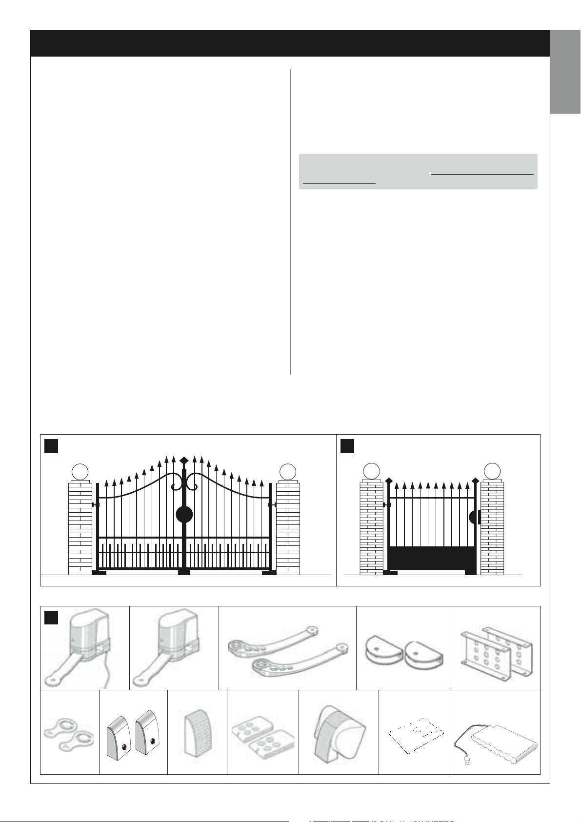
KNOWLEDGE OF THE PRODUCT AND PREPARATION FOR INSTALLATION
STEP 2
2.1 – PRODUCT DESCRIPTION AND INTENDED USE
The series of devices that make up this product serve to automate a 2leaf gate or door (fig. 1a). It may also be used to automate a single leaf
gate or door (fig. 1b).
Any other use than as specified herein or in environmental conditions other than as stated in STEP 3 is to be considered improper
and is strictly prohibited!
The main part of the automation comprises two electromechanical gearmotors each equipped with a 12 V dc motor and a straight toothed
reduction gear. One of the gearmotors is also fitted with a control unit.
The control unit governs all devices present in the automation and manages all relative functions. It is made of a board and incorporated radio
receiver which receives the commands sent by a transmitter. It may also
be controlled via a wall-mounted keypad or a pair of photocells set with
the single opening command.
The control unit is able to manage different types of manoeuvre, each programmable and usable according to specific needs.
Other special functions are also available to enable personalisation of the
automation parameters.
The automation is designed for use of various accessories that enhance
functionality and guarantee optimal safety. In particular, the control unit
can memorise up to 150 keys of MT4 transmitters; up to 4 MK control
keypads or alternatively up to 4 pairs of MP photocells, set for the opening command only.
Connections of the various devices are by means of the “Bus” system.
This system reduces complexity of the connections between devices, as
it envisages the use of a single cable between one device and another.
The product is mains powered and in the event of a power failure it
enables manual release of the gearmotors for manual movement of the
gate leafs.
In this situation, the gate can also be opened using the buffer battery (MB
model) if fitted on the system.
English
2.2 – COMPONENTS USED TO SET UP A
COMPLETE SYSTEM
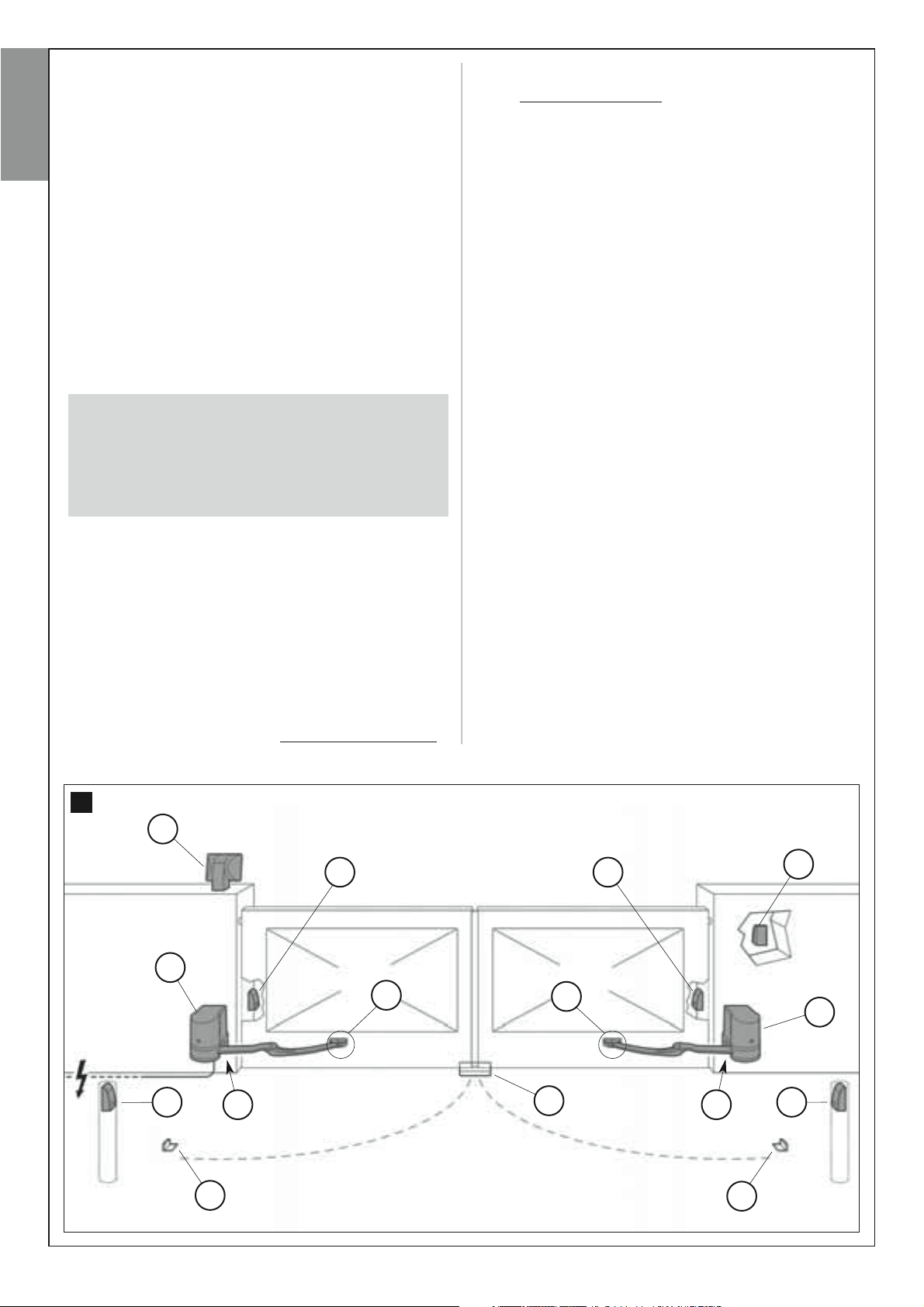
Fig. 2 illustrates all components used to set up a complete system, such
as that shown in fig. 8.
WARNING!
Some components shown in fig. 2 are optional and may not be
supplied in the pack.
List of components:
[a] - Electromechanical operator with control unit
[b] - Electromechanical gearmotor without control unit
[c] - Curved arms
[d] - Front brackets (for fixing gearmotors onto gate)
[e] - Rear brackets (for fixing gearmotors onto wall)
[f] - Keys for manual release of gearmotors
[g] - Pair of photocells model. MP (for wall-mounting)
[h] - Control keypad model. MK (for wall-mounting)
[i] - Portable transmitter model. MT4
[l] - Flashing light model. MF
[m]- Metal hardware (screws, washers, etc.)
[n] - buffer battery mod. MB
1a 1b
2
a b
h l m nf g
i
dc
e
English – 5
STEP 3
PRELIMINARY CHECKS FOR INSTALLATION
Before proceeding with installation, check the condition of the product
components, suitability of the selected model and conditions of the
English
intended installation environment.
IMPORTANT –The gearmotors cannot be used to power a gate that
is not fully efficient and safe. Neither can it solve defects caused by
poor installation or insufficient maintenance of the gate itself.
3.1 – CHECKING SUITABILITY OF THE ENVIRONMENT
AND GATE TO BE AUTOMATED
• Ensure that the mechanical structure of the gate complies with current
national standards and that it is suitable for automation. (
to the information specified on the gate dataplate
• Move the gate leafs manually to
ment has the same degree of friction throughout all points of travel (
increase in friction must occur
• Manually move the leafs to any position and leave stationary, ensuring
that they do not move from this position.
• In the area for mounting the gearmotor, ensure that there is sufficient
space for rotation of the arm (fig. 7).
• Ensure that the space around the gearmotors enables safe and easy
manual release of the leafs.
• Ensure that the selected surfaces for installation of the various devices
are solid and guarantee a stable fixture.
• Ensure that all devices to be installed are in a sheltered location and pro-
tected against the risk of accidental impact.
• Ensure that the selected surfaces for fixing the photocells are flat and
enable correct alignment between photocells.
open
and
close
).
3.2 – CHECKING PRODUCT APPLICATION LIMITS
The gearmotors must be installed by fixing the relative rear support to the
wall (or column) of the gate and the arm support bracket on the leaf of the
gate.
To ascertain suitability of the product with respect to the specific features
of the gate and area to be automated, the following checks should be
performed as well as a check for compliance of the technical data in this
paragraph and the chapter “Product technical specifications”.
If present, refer
).
, checking that move-
2 – Ensure that the minimum and maximum temperature of the installation
environment is within the temperature limits set for operation of this product. Refer to the technical data in the chapter “Product technical specifications”.
3 – Considering the source from which the power line is supplied (if
already fitted) used to power the system, select which gate leaf is to be
used to mount the gearmotor with control unit.
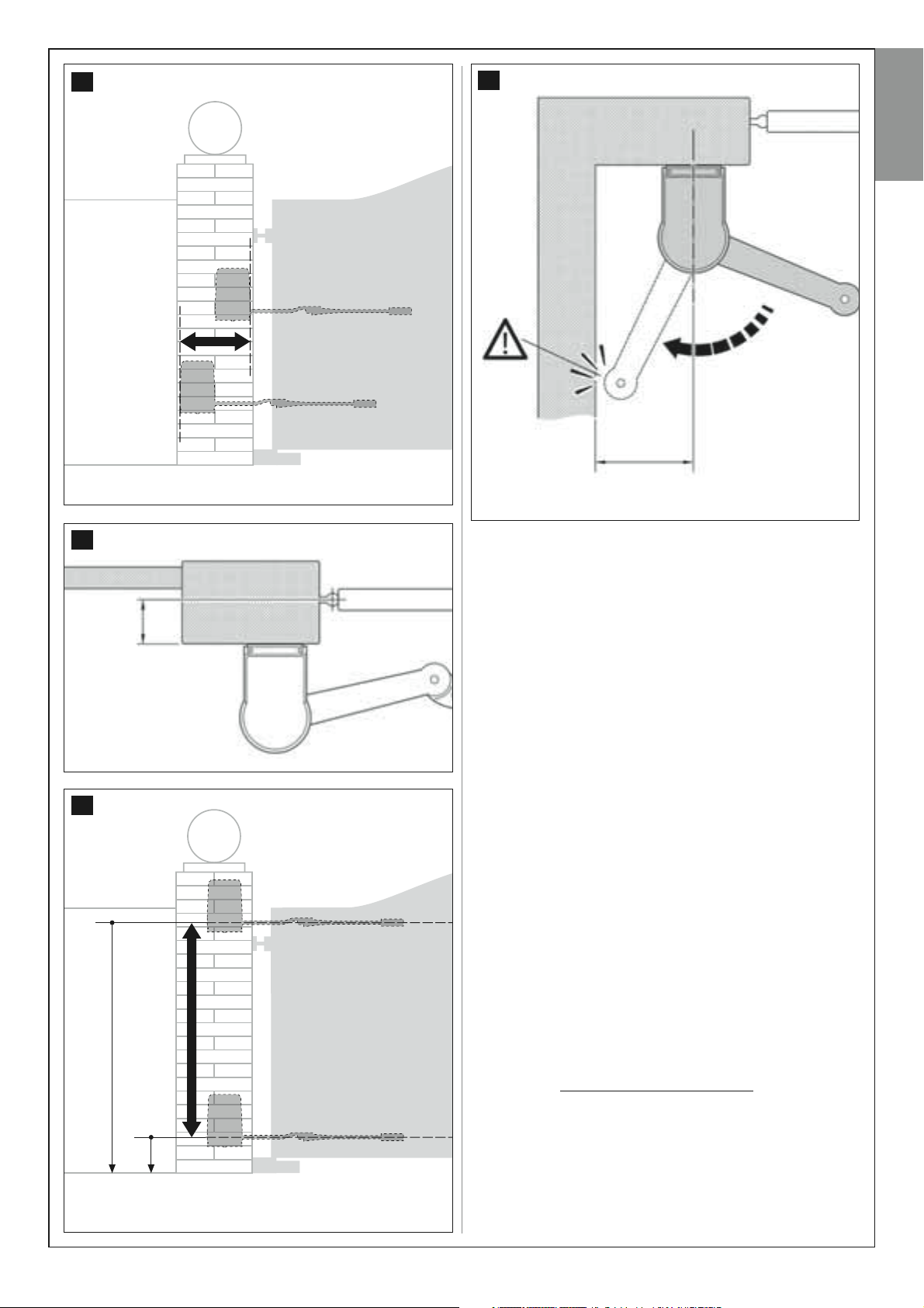
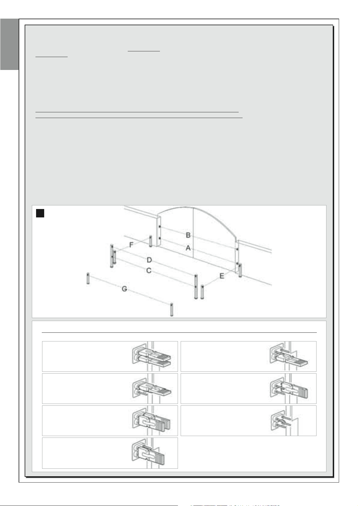
4 – On each leaf and the adjacent wall (or column) ensure that there is
sufficient space to fit the gearmotor, with reference to the values shown in
figs. 3-4-5-6-7 and the following notes:
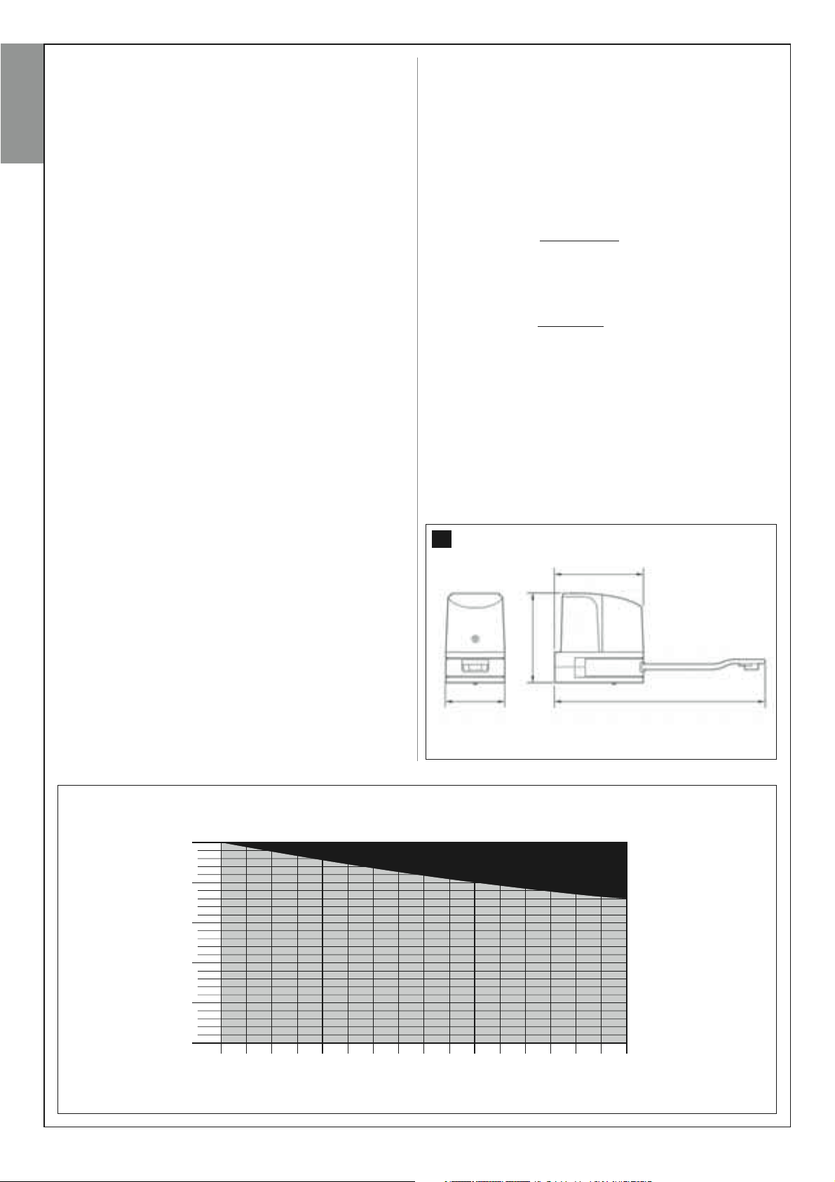
a) Fig. 3: indicates the overall dimensions of the gearmotor.
b) Fig. 4: indicates the horizontal space within which the rear gearmotor
support is to be fitted. The exact point at which to position this support
must be calculated with reference to point 02 of STEP 5.
c) Fig. 5: Indicates the maximum measurement “B” required between the
point of leaf rotation and the surface of the wall on which the rear gearmotor support is fixed.
d) Fig. 6: indicates the vertical space within which the gearmotor is to be
no
fitted. Measurement “D” specifies the minimum distance from the ground
(the recommended minimum ground clearance is 200 mm). Measurement
“C” (maximum distance from ground) depends on the height of the gate
leaf.
e) Fig. 7: Indicates the minimum measurement “E” (400 mm) required
between the gearmotor arm and a possible obstacle present when the
leaf is totally open (wall, edge of a flowerbed etc.).
ment must be taken starting from the centreline of the gearmotor.
Note – This measure-
3
235 mm
235 mm
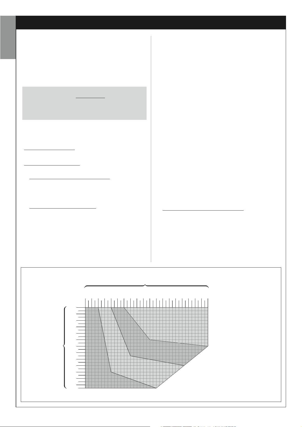
1 – Ensure that the dimensions and weight of each leaf are within the following limits of use, with reference to graph 1.
- maximum width 1.8 m;
- maximum height 2 m;
- maximum weight 250 kg.
GRAPH 1
kg 250
200
150
100
Gate leaf weight
50
0
1,0
1,1
1,2
1,3 1,4
Gate leaf width
155 mm 550 mm
1,5
1,6
1,7
1,8 m
6 – English
4
7
English
E
Measurement E = minimum 400 mm
5
B
STEP 4
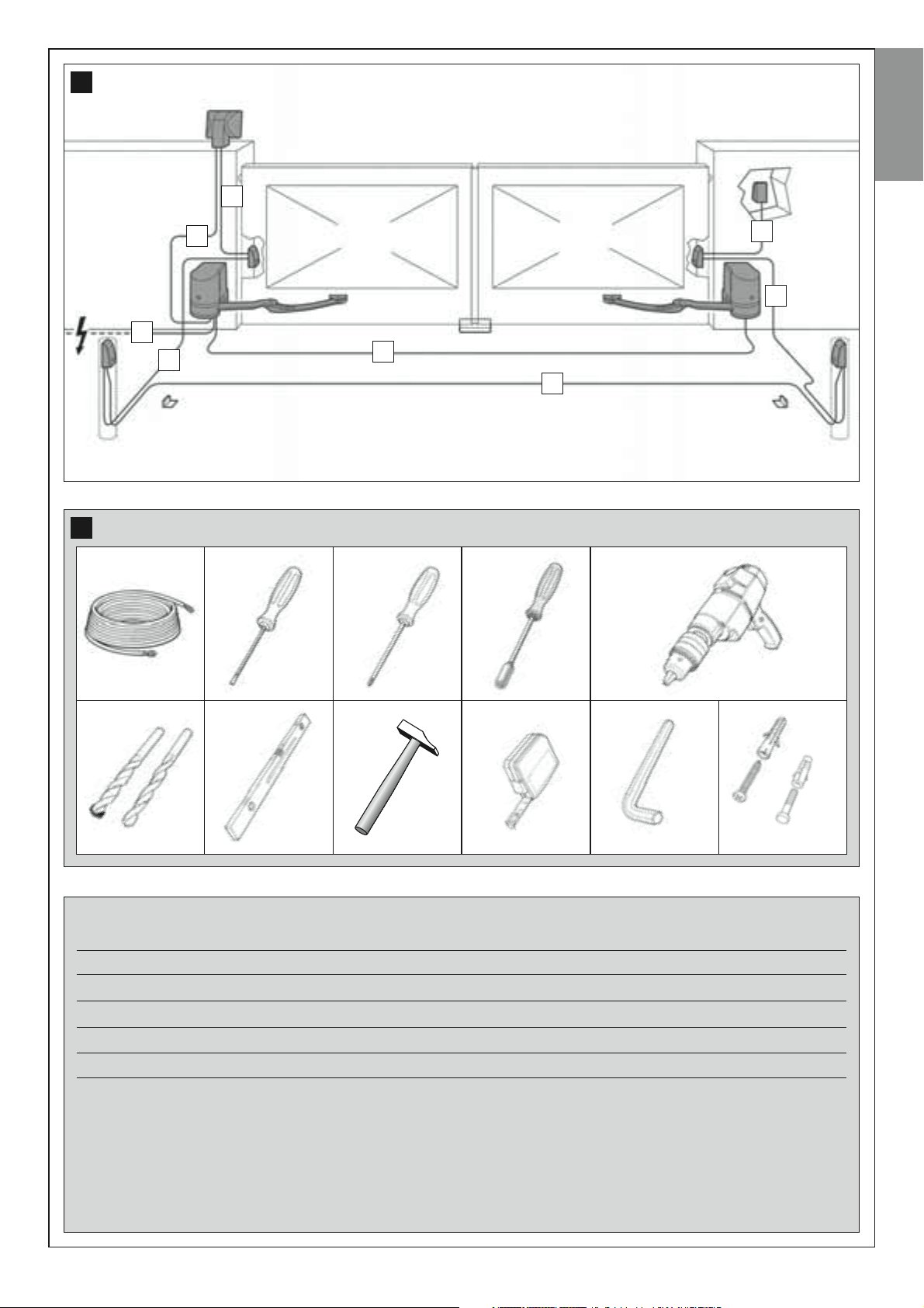
4.1 – PRELIMINARY SET-UP WORK
4.1.1 –
Typical reference system
Fig. 8 is an example of an automation system set up using the various
components of Moovo. These parts are positioned according to a typical
standard layout. The following components are used:
a - Electromechanical gearmotor with control unit
b - Electromechanical gearmotor without control unit
6
c - Rear supports (wall-mounted)
d - Front brackets (on leaf)
e - Pair of photocells (wall-mounted)
f - Flashing light
g - Control keypad (wall-mounted)
h - pair of posts for photocells
i - Mechanical stops on
may terminate against a natural stop, i.e. wall, edge of a flowerbed etc. –
or use a mechanical limit switch present on the gearmotor)
l - Mechanical stop on
Opening (Note – Alternatively, leaf movement
Closing
C
D
Measurement D = minimum 200 mm
4.1.2 –
Establishing positions of components
With reference to fig. 8, locate the approximate position for installation of
each component envisaged in the system.
Establishing the device connection layout
4.1.3 –
The product envisages a “Bus” type connection between all system
devices, using a single cable with two electrical wires
nection, data communication between devices is via cable, using the specific protocol named “Bus-Moovo”. Caution!
with this protocol may be installed in the system.
On a “Bus” network, devices can be connected using various connection
layouts, and in each one, each device becomes a node of this network.
The possible connection layouts are the following:
star
”: In this configuration, each device is autonomous as it is connect-
– “
ed directly to the two Bus terminals on the control unit.
chain
– “
”: In this configuration one device is connected to another and
. In this type of con-
– only devices compatible
English – 7
the latter to another and so on, like links of a chain. Therefore only the first
device in the chain is connected to the two Bus terminals on the control
unit.
– “
mixed
urations described above.
English
To select the most suitable connection configuration for the connection of
all system devices, refer to the example shown in fig. 9 / fig. 26. In gener-
al, it is recommended to connect the flashing light as the first device connected to the control unit.
4.1.4 –
Before starting installation, ensure that there is all equipment and materials required for the work concerned (see example in fig. 10); also ensure
that all items are in good condition and comply with local safety standards.
4.1.5 –
Lastly, dig the routes for the ducting used for electrical cables, or alternatively external ducting can be laid, after which the pipelines can be
embedded in concrete and other preparation work for the installation can
be completed to finalise the site ready for subsequent installation operations.
”: This configuration comprises a combination of the two config-
Check all tools required for the work
Complete set-up work
WARNINGS
– Position the gearmotor with control unit in the vicinity of the
point of electrical mains connection, if already present.
– Position the ends of the ducting used for electrical cables in
the vicinity of the points envisaged for fixture of the various components.
– In the “chain” configuration”, the sum of the lengths of each cable
used to connect one device to the other and, last of all, to the Control Unit MUST NOT exceed 20 m.
– If connecting other devices between the Control Unit and the flashing lamp, use the same cable for these devices as was used for the
flashing lamp.
– All operations to lay the electric cables and connect them to the
various devices must be carried out during installation of the components.
Note:
• The ducting serves to protect electrical cables and prevent accidental
damage in the event of impact.
• The “fixed” control devices must be visible from the gate but positioned
far from moving parts.
4.2 – PREPARING THE ELECTRICAL CABLES
When preparing the electrical cables required for your system, please
refer to fig. 9 and “Table 1 – Technical characteristics of the electric
cables”. In addition to this, you should always remember the following:
– In the “star” configuration, NONE of the individual cables linking up
any of the devices to the Control Unit may exceed 20 m in length.
8
f
e e
a
g
8 – English
d
c c
d
l
i
b
hh
i
9
English
D
10
A
D
D
B
D
C
D
TABLE 1 – Technical specifications of electric cables
(note 1)
Connection Cable type Maximum admissible length
A - FLASHING LIGHT cable Cable 2 x 1.0 mm
B - POWER SUPPLY cable Cable 3 x 1.5 mm
C - MOTOR cable Cable 3 x 1.5 mm
D - BUS cable Cable 2 x 0.5 mm
2
2
(note 2)
2
2
10 m
(read paragraph 4.2)
30 m
10 m
20 m
(read paragraph 4.2)
Note 1 – The cables required for the set-up of the system (not included in the pack) may vary according to the quantity and type
of devices envisaged for the installation.
Note 2 – If the power cable supplied is not long enough, replace with a cable of this type. This task must be performed by skilled
and qualified personnel: Refer to the section “Tasks reserved for qualified technicians”.
CAUTION! - The cables used must be suited to the installation environment; for example a cable type H07RN -F for outdoor environments is recommended.
English – 9
INSTALLATION: ASSEMBLY AND CONNECTION OF COMPONENTS
STEP 5
English
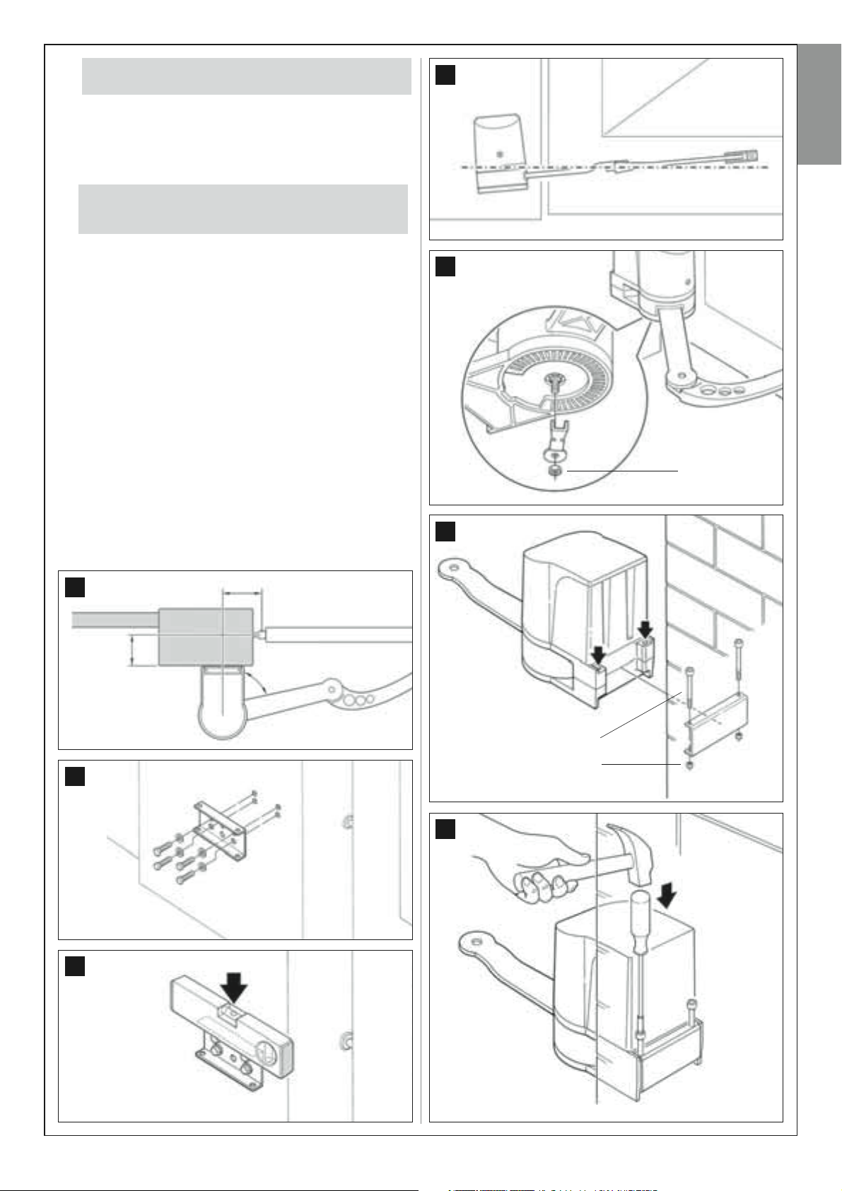
5.1 – INSTALLING THE AUTOMATION COMPONENTS
WARNINGS
• Incorrect installation may cause serious physical injury to those
working on or using the system.
• Before starting automation assembly, make the preliminary checks
as described in STEP 3.
IMPORTANT! –
the “physical” installation of
mated is a two-leaf model, repeat the same operations to install the
second gearmotor. In particular, to install the gearmotor with control
unit, refer to STEP 6 to establish on which gate leaf it is to be
installed.
Wall-mounting of the rear gearmotor bracket
To fix the rear bracket to the wall or column of the gate, its position both
vertically and horizontally must be established as follows:
– Vertically positioned (fig.
and in fig. 5; then, after locating the position, use a pencil to trace a horizontal line on the wall (or column).
– Horizontally positioned (fig. 4): to position the gearmotor horizontally,
use Graph 2 and proceed as follows:
01. Establish the
move the gate leaf to the maximum opening position required (take
care to observe the warning in 4-d in STEP 3.2) and measure the
degrees of the leaf opening angle using the goniometer figure shown
on the last page of this manual.. Then locate and highlight the corresponding angle area in grey on Graph 2.
02. Establish
With reference to fig. 11 measure value B in your specific context.
This value is the distance between the gate leaf rotation fulcrum and
the surface for mounting the rear bracket. Then on the graph, highlight value B and from this point trace a horizontal line until it inter-
cepts the angle area located in he above point. In this area, the
traced line establishes two points; from these two points, trace a vertical line upwards until the right angle of value A is intercepted. The
area formed by these lines indicates value A, i.e. the possible measurements usable for fixing the rear bracket.
03. At this point, mark the value found on the wall (or column) and then
trace a vertical line passing through this point. Then, with reference to
The following assembly phases (STEP 5) illustrate
a single gearmotor.
5): follow the general instructions in STEP 3
maximum leaf opening angle:
position B and position A:
If the gate to be auto-
the lines marked out on the wall, position the rear bracket on the surface in the required position and use a pencil to mark the drilling holes.
04. Drill the holes in the wall, insert the plugs (minimum 8 mm; not sup-
plied) and fix the support using suitable screws and washers (fig.
12). Important – Ensure that the bracket is perfectly level; an offset
gearmotor can cause automation malfunctions (fig. 13 and 14).
Note – The screws required for fixing the bracket on the wall are not
included in the pack, as their type depends on the material and thickness of the wall in which they are inserted.
05. Using a 13 mm wrench remove the mechanical limit switch on the
lower side of the gearmotor (fig. 15): loosen and remove the lock nut
of the mechanical limit switch screw.
06. Insert the rear section of the gearmotor in the relative space on the
fixing bracket, taking care to align the holes on the motor with those
on the bracket (fig. 16).
07. Hold the gearmotor with one hand and use the other to insert the
two screws supplied in the holes. Note
– If the screws are difficult to
insert, use a mallet and tube screwdriver to insert them completely
(see fig. 17). Then secure the screws with the relative nuts; to do this
use a hex wrench to hold the screw head in place and a tube screwdriver (10 mm), with maximum external dimensions of 14.5 mm, to
tighten the nut.
08. At this point secure the curved arm to the gearmotor. IMPORTANT!
The arm must be positioned with the curve facing the gate
–
leaf. Then insert the gearmotor “extension” head in the hole of the
curved arm and secure the assembly with the screw, washer and nut
supplied
09. To secure the gate leaf connecting bracket, proceed as follows:
a) Insert the bracket in the end of the curved arm, aligning the
respective holes and insert the pin supplied (without the stop benz-
ing - fig. 19).
b) Use the special key to release the gearmotor (refer to the chapter
“Manually locking and releasing the gearmotor” in the “Operation
Manual”).
c) Move the gate leaf to the maximum
position the arm at its maximum extension
the arm towards the leaf completely up against the fixing bracket.
d) At this point, use a pencil to trace the drilling holes and then drill
the leaf as required.
(fig. 18).
Closing
position required and
(fig. 20). Then move
Note – The screws required for fixing the bracket on the gate leaf are
not included in the pack, as their type depends on the material and
thickness of the gate in which they are inserted.
10. Detach the bracket from the gearmotor arm and secure to the gate
leaf. Important – Ensure that the bracket is perfectly level.
11. Secure the gearmotor arm to the bracket, inserting the pin and stop
benzing supplied.
GRAPH 2
10 – English
B
(mm)
100
120
140
160
180
200
220
240
A (mm)
110
120
130
140
150
160
170
180
190
200
210
220
230
240
250
260
270
280
290
300
0
20
40
60
80
° 101 ÷ 105
96° ÷ 100
90° ÷ 95°
106° ÷ 110°
Our example:
Maximum leaf opening angle = 98°;
value B = 120 mm; value A is usable from
142 mm to 174 mm.
CAUTION! – If the installation site is not equipped with
12.
mechanical stops on the ground refer to STEP 5.2.
13. With the gearmotor still released, manually move the two gate leafs
to the position shown in fig. 21 and use the special key to lock the
gearmotor (refer to the chapter “Manually locking and releasing
the gearmotor” in the section “TECHNICAL DOCUMENTATION”).
Then move the gate leaf slightly by a few centimetres in the direction
of maximum
If the gate to be automated is a two-leaf model, repeat the
14.
same operations as described in this STEP 5 to install the
second gearmotor.
Opening
until a click can be heard.
14
English
15
M8
11
12
16
A
B
V6 x 70
M6
17
13
English – 11
18
V8 x 35
English
19
R8/40
M8
Stop benzing
04. To facilitate fixture of the mechanical limitswitch, add a piece of
adhesive tape through to the base of the gearmotor, as shown in
fig. 23.
05. Position the mechanical limit switch as follows: If working on the
gearmotor that operates the left leaf, the mechanical limitswitvch
must be fixed on the left of the adhesive tape, adjacent to it; vice versa if working on the right leaf gearmotor, this should be fixed to the
right of the adhesive tape, adjacent to it (fig. 24). Then secure by
means of the locknut (fig. 25).
06. At this point manually move the gate leaf and check that it stops
exactly in the required maximum
occur, move the mechanical limit switch by one or two “teeth” and
check the maximum
07. Lastly, with the gearmotor still released, manually move the gate leaf
to approximately mid-travel and block the gearmotor by means of
the special key (refer to the chapter “Manually locking and releasing
the gearmotor” in the “Operation Manual”). Then move the gate leaf
slightly by a few centimetres in the direction of maximum Opening
until a click can be heard.
Opening
Opening
position again.
position. If this does not
22
20
21
23
Maximum
24
5.2 – ADJUSTMENT OF THE MECHANICAL LIMIT SWITCH
ON
OPENING
If the installation site is not equipped with mechanical stops on the ground
used to stop the gate at the end of the
mechanical limit switch on the lower side of each gearmotor as follows:
01. With the gearmotor released, manually move the leaf to the
position.
02. Locate the centreline (axis) of the gearmotor arm and mark it with a
piece of adhesive tape placed on the fixed section of the gearmotor,
above the arm (fig. 22).
03. Then close the gate leaf.
Opening
manoeuvre, adjust the
Opening
12 – English
25
STEP 6
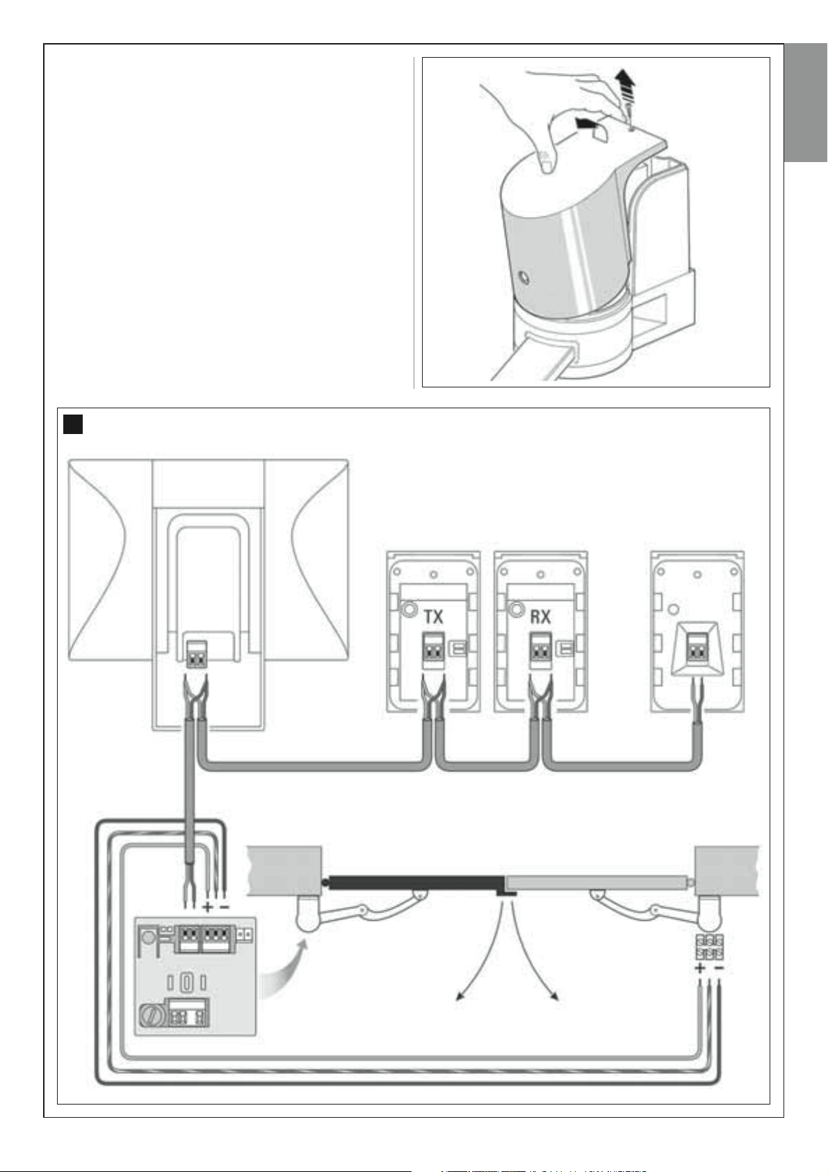
INSTALLATION AND CONNECTIONS OF SYSTEM DEVICES
Install and connect the system devices with reference to the STEPS
below and the example in fig. 26.
CAUTION! – Strictly observe the electrical connections specified in
this paragraph, as incorrect connections could lead to serious faults
or hazards.
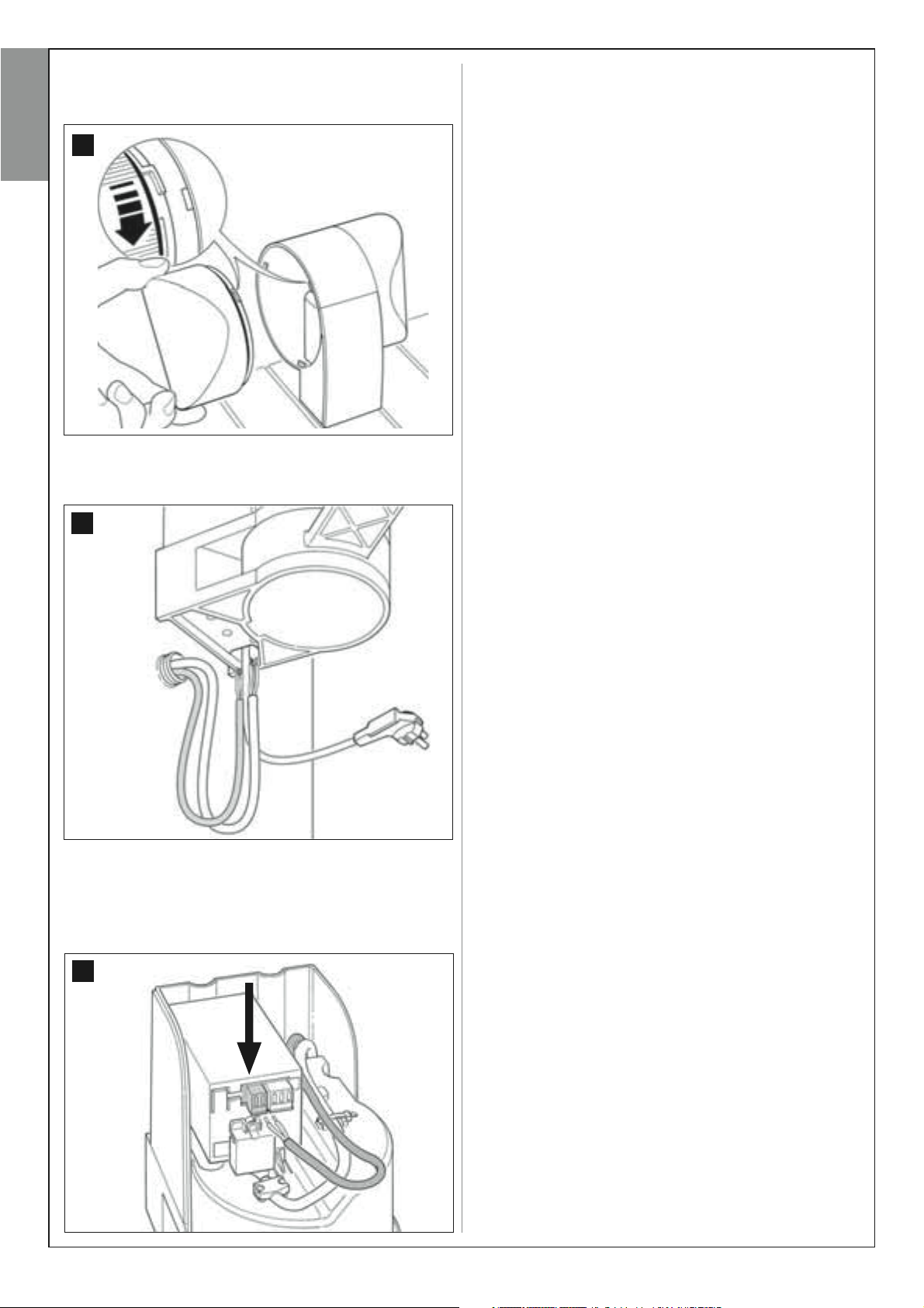
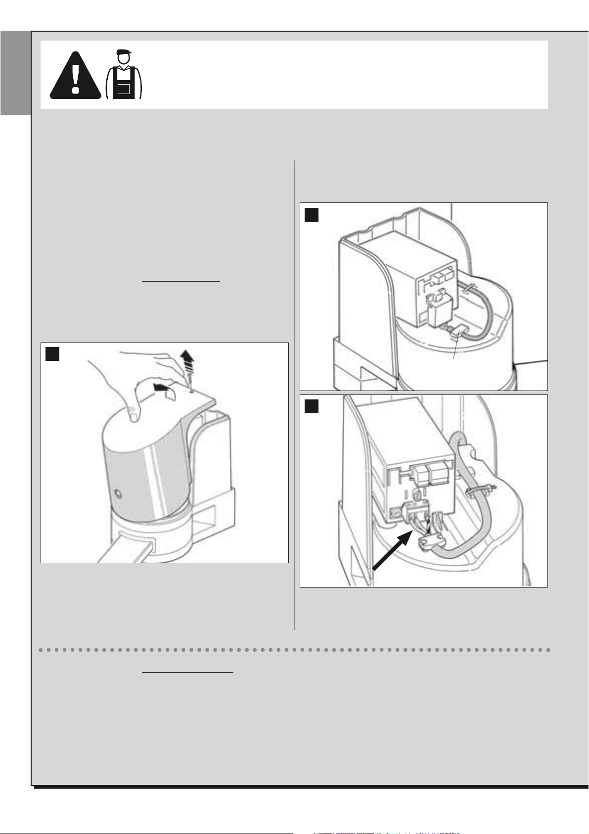
To access the control unit, remove the cover from the gearmotor with
control unit as follows (see figure alongside).
a) Loosen the screw on the top of the cover using a Phillips screwdriver.
b) Place two fingers on the two cavities on the rear of the germotor and lift
the cover by pulling upwards, using the base as leverage.
26
Flashing light
English
“BUS SYSTEM” DEVICE
CONNECTION LAYOUT
Pair of photocells Keypad
English – 13
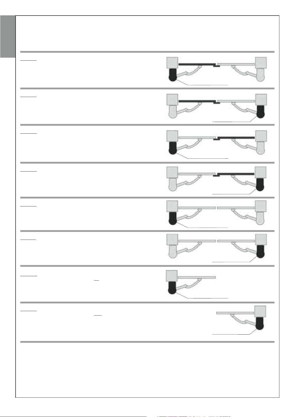
6.1 – SETTING THE GATE LEAF OPENING SEQUENCE
To set the correct order of gate leaf opening on the Control unit, select the ideal configuration from those below and proceed as described.
To carry out the specified tasks, it may help to remove the control unit from its seat, as described in the section “Removing the control unit from the
gearmotor”.
EnglishItalianoFrançaisEspañolDeutschPolskiNederlands
Case A: No modifications required.
Control unit
Case B: (on control unit) proceed as follows:
- locate electric jumper “Sel” and move it from its original position shown in fig.
27 to the new position shown in fig. 28
– invert the position of the wires on the terminal board marked “Motor 2” (fig. 29).
– invert the position of the wires on the terminal board marked “Motor 1”(fig. 30).
Case C:
- (on control unit), locate electric jumper “Sel” and move it from its original
position shown in fig. 27 to the new position shown in fig. 28
Control unit
Control unit
Case D: (on control unit) proceed as follows:
– invert the position of the wires on the terminal board marked “Motor 2”(fig. 29).
– invert the position of the wires on the terminal board marked “Motor 1”(fig. 30).
Case E: No modifications required.
Case F: (on control unit) proceed as follows:
– invert the position of the wires on the terminal board marked “Motor 2”(fig. 29).
– invert the position of the wires on the terminal board marked “Motor 1”(fig. 30).
Case G: For automation of a gate or door with a single leaf, where the gear-
motor with control unit is positioned on the left, proceed as follows:
– (on control unit), locate electric jumper “Sel” and move it from its original
position shown in fig. 27 to the new position shown in fig. 28
Case H: For automation of a gate or door with a single leaf, where the gear-
motor with control unit is positioned on the right, proceed as follows:
– (on the control unit), locate electric jumper “Sel” and move it from its original
position shown in fig. 27 to the new position shown in fig. 28
– (on the control unit) invert the position of the wires on the terminal board
marked “Motor 1”(fig. 30).
Control unit
Control unit
Control unit
Control unit
Control unit
14 – English
Motor 2
Motor 1
27
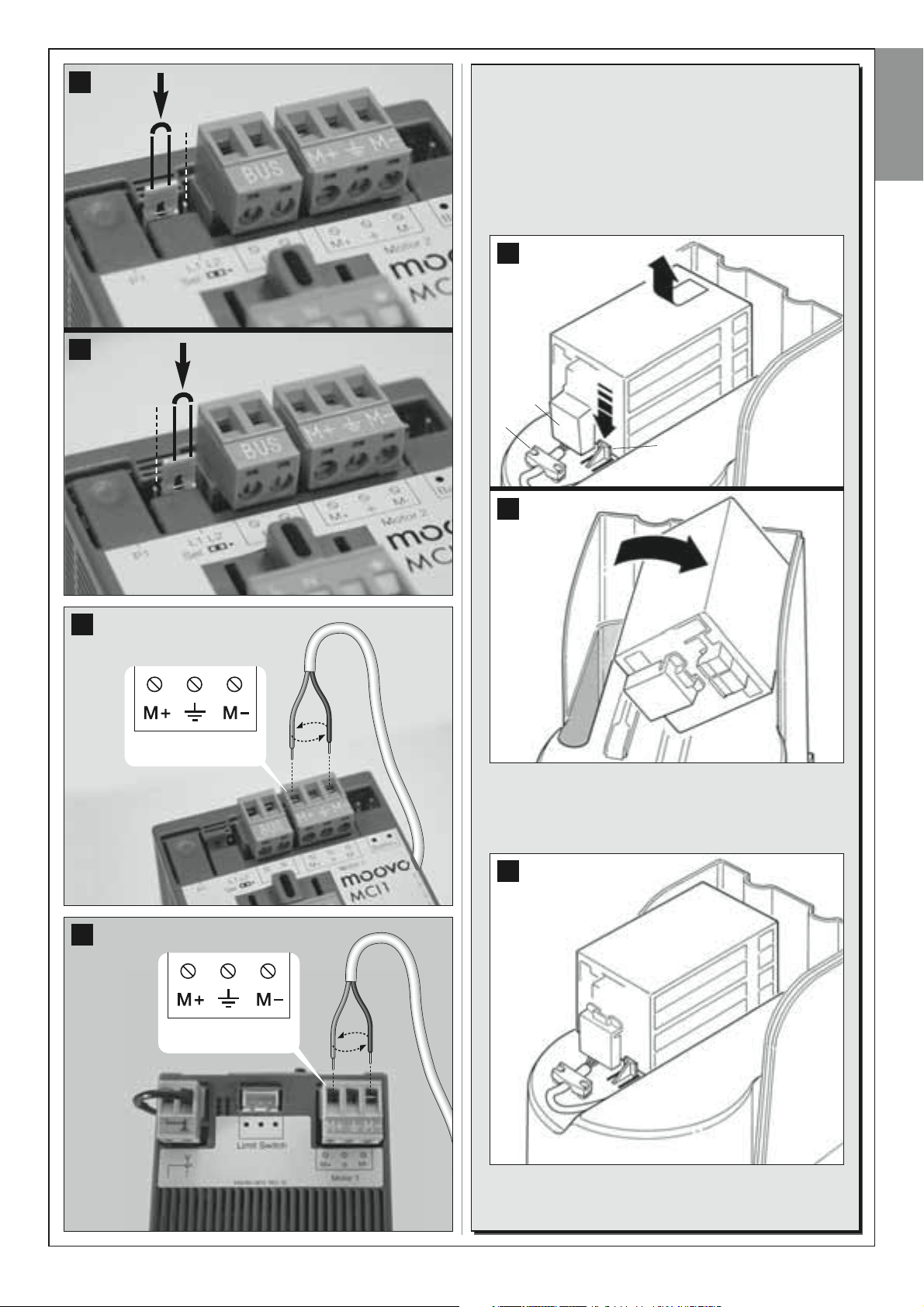
REMOVING THE CONTROL UNIT FROM
THE GEARMOTOR
28
01. Using a Phillips screwdriver, loose the cable clamp screws
(fig. 31-a) and the terminal board cover (fig. 31-b) to facilitate
removal of the control unit from its seat.
02. Fig. 31-32: press a finger on the tab (fig. 31-c) locking the
control unit and with the other hand remove the control unit
from its seat by pushing it forwards and upwards at the same
time to detach it from the guide.
31
b
a
c
32
English
29
30
03. Fig. 33: after completing the work, refit the control unit in its
seat as follows:
a) position the control unit above the tab (fig. 31-c) then push
it down and pull backwards until it clicks into place.
Then refit the terminal board cover and cable clamp.
33
English – 15
6.2 – INSTALLING AND CONNECTING
THE GEARMOTOR WITHOUT CONTROL UNIT
If the system envisages the use of two gearmotors, connect the gearmotor without control unit to the version with control unit as follows:
English
01. Fig. 34:
a) On the gearmotor without control unit, loosen the screw on the
top of the cover using a Phillips screwdriver.
b) Place two fingers on the two cavities on the rear of the germotor
and lift the cover by pulling upwards, using the base as leverage.
34
02. Fig. 35:
Pass the connection cable through the hole on the lower side of the
gearmotor.
04. Fig. 37:
On the gearmotor with control unit, remove the cover and pass the
connection cable from the other gearmotor through the hole on the
lower side.
37
05. Fig. 38:
b) Remove the power terminal board from its seat to enable loosening of the three terminal screws.
c) Proceed with connection of the cable wires, observing the symbols on the terminal board and refit the latter in its seat.
38
35
03. Fig. 36:
Connect the cable wires to the respective terminals observing the
symbols. Then secure the cable with the clamp.
36
16 – English
6.3 – INSTALLING AND CONNECTING
FLASHING LIGHT MODEL MF
This flashing device indicates execution of each manoeuvre. It is also connected to the diagnostics system of the control unit and in the event of
malfunctions signals the type of problem by means of a pre-set sequence
of flashes (see paragraph “What to do if…”).
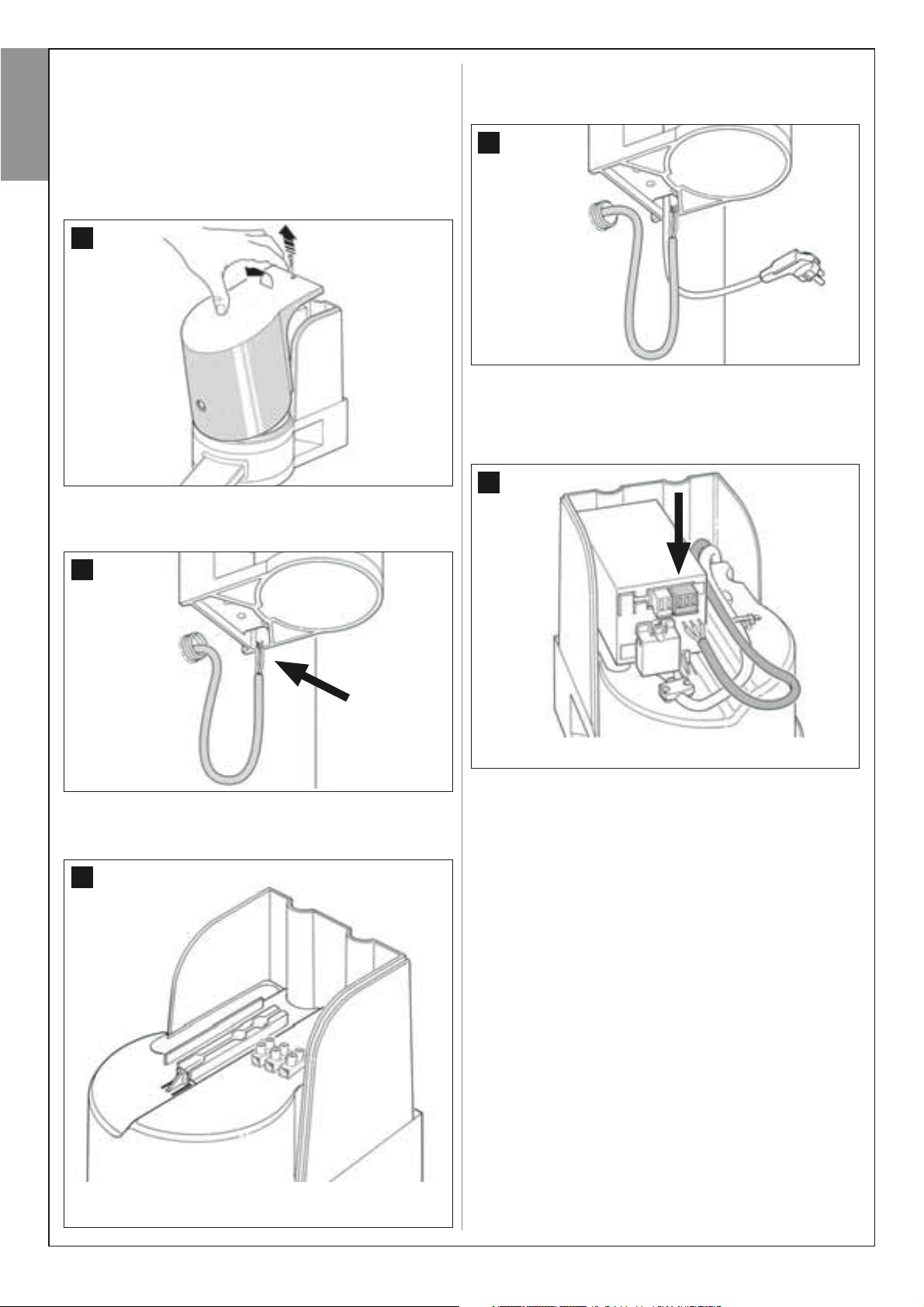
To install and connect the flashing light proceed as follows:
01. Fig. 39:
Extract one of the two transparent covers, turning it anti-clockwise
and set aside.
39
02. Fig. 40:
Use two fingers and at the same time press the two tabs at the bot
tom and use the other hand to remove the external cap of the flashing light.
04. Fig. 42:
CAUTION! – never assemble the product in a position other
than those specified.
42
English
05. Fix the body of the flashing light to the wall with the relative screws,
routing the cables through the prepared holes.
06. Fig. 43:
a) Connect the wires of the two cables and secure on the terminal
board.
b) Lock the cable by means of the relative cable clamp.
-
43
40
03. Fig. 41:
Drill the marked sections on the base of the flashing light for fixture of
the screws and routing of the cables.
41
07. Fig. 44:
Insert the cap of the flashing unit in its seat until the tabs click in
place.
44
English – 17
08. Fig. 45:
Refit the transparent cover in its seat and turn clockwise, taking care
that the serrated section engages with those on the flashing light
body.
45
English
09. Fig. 46:
On the gearmotor with control unit, pass the connection cable of the
flashing light through the hole on the lower side.
46
10. Fig. 47:
a) On the control unit, remove the BUS connection terminal board
from its seat to enable loosening of the 2 terminal screws.
b) Proceed with connection of the cable wires, observing the symbols on the terminal board and refit the latter in its seat.
c) Then tighten the cable clamp to secure the cable to the gearmotor.
47
18 – English
6.4 – INSTALLING AND CONNECTING
PHOTOCELL MODELS MP
The pair of photocells is made up of one photocell that transmits (named
TX) and one that receives (named RX). TX and RX are marked by a label
inside the cover. The photocells are installed on each side of the point of
transit and are connected to the control unit via the flashing light by
means of the BUS cable.
The photocells are safety devices that enable the detection of obstacles
when the latter cross the trajectory of the two photocells. The system can
be equipped with up to 6 pairs of photocells for safety
tocells used to command an
al photocells, refer to section “
pairs
”).
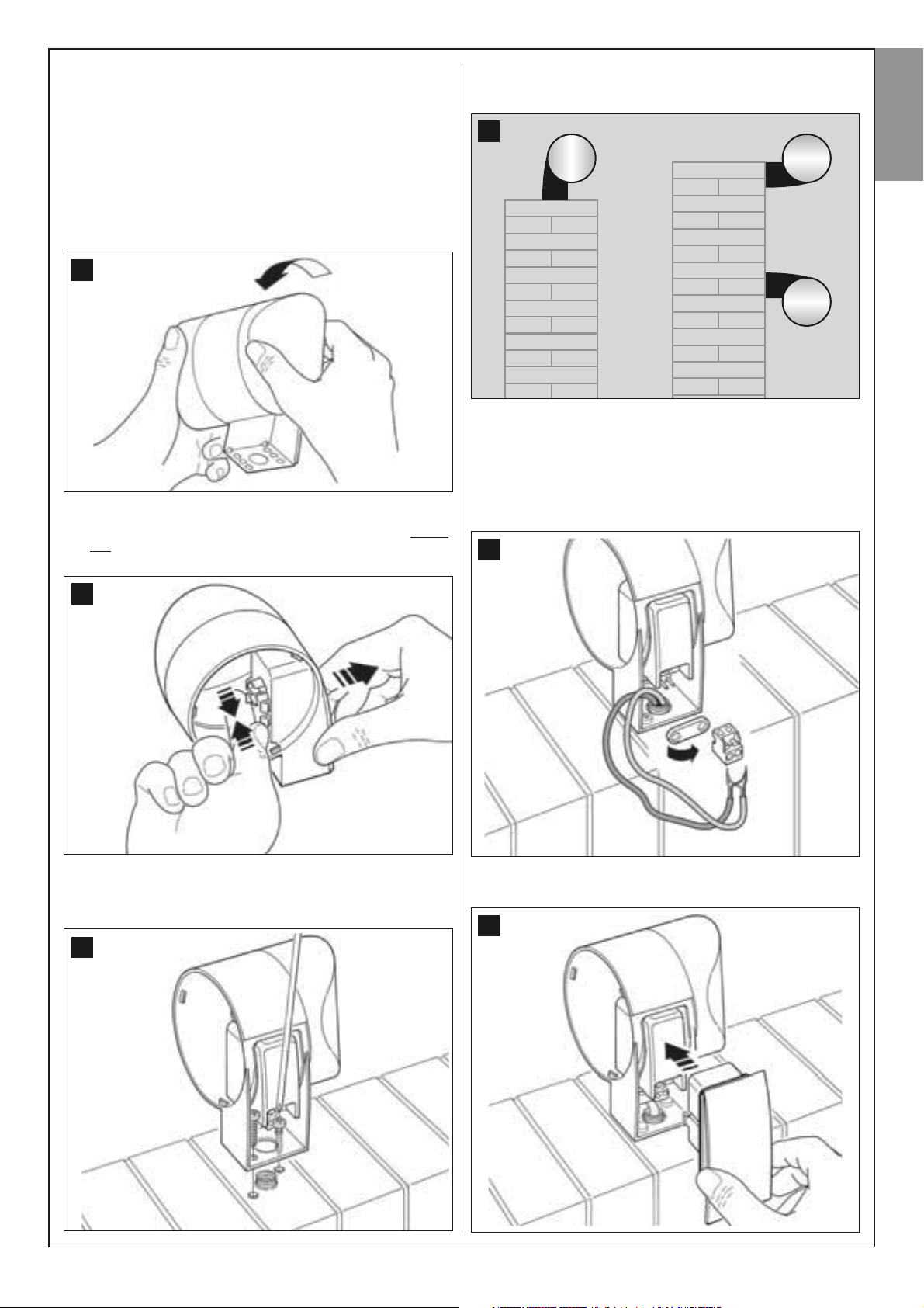
To install and connect a pair of photocells proceed as follows:
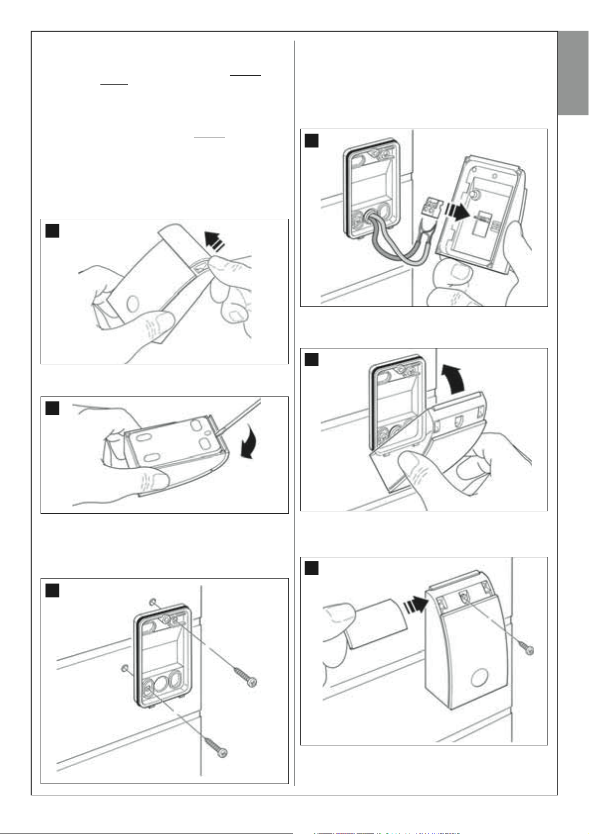
01. Fig. 48:
Remove the screw cover cap by pushing down one side as shown in
the figure.
Opening
manoeuvre only (to install addition-
Selecting operating modes of photocell
and a pair of pho-
48
04. Fig. 51:
a) Connect the wires of the two cables and secure on the terminal
board.
b) Insert the terminal board in the male connector at the rear of the
photocell.
IMPORTANT! – Before closing the photocell, the photocell operating
mode must be selected by means of the relative jumper (refer to section “
Selecting operating modes of photocell pairs
”).
51
05. Fig. 52:
Refit the cover, ensuring that the serrated section engages with that
of the photocell base.
English
02. Fig. 49:
Using a screwdriver, open and detach the base of the photocell.
49
03. Fig. 50:
a) Drill a hole on the pre-cut section on the base for routing the connection cables.
b) Fix the photocell base to the wall with the relative screws, routing
the cables through the prepared hole.
50
52
06. Fig. 53:
Fix the photocell cover to the base by means of the screw supplied.
Lastly refit the screw cover cap as shown in the figure.
53
English – 19
Additional pairs of photocells can be installed at any time on a system for swing gates.
Up to a maximum of 6 pairs of photocells with safety functions can be added (as shown in the example A-B-C-D-E-F in fig. 54) and 1 pair with
English
a control function (as shown in the example G in fig. 54) which performs an
For the correct location of these pairs of photocells, refer to fig. 54.
In order for the control unit to recognise each pair of photocells and the specifically assigned function, the devices must be assigned with
addresses by the insertion of one or two electric jumpers (Tab l e 3 ) or no jumper at all (Ta b le 3). In this way when the control unit receives the
input from the photocells it will activate the motor for the corresponding manoeuvre.
The address assignment procedure is performed both on the TX and RX photocell as follows:
For photocells “A-B-C-D-E-F”
Take care to observe the following warnings:
• the electric jumpers must be positioned on the two photocells using the same configuration
• the same configuration used on one pair of photocells must NOT be used on other photocells.
To program these pairs of photocells (if fitted on the system) proceed as follows:
01. Open the cover of the photocell.
02. In fig. 54 locate the position in which the specific photocells are installed.
03. In Tab l e 3 select the required configuration and insert electric jumpers in the two photocells.
For photocells “G”
Take care to observe the following warnings:
• These photocells have a different function from the other (controlling the automation), and therefore must be positioned at a specific distance
to avoid possible interference.
• These photocells remain powered also when the automation is on standby and in the event of a power failure, if the buffer battery is fitted, this
will reduce the standard lifetime (see STEP 6.6).
To program these pairs of photocells (if fitted on the system) no electric jumper must be inserted (see Tab l e 3 ).
SELECTING THE OPERATING MODE OF THE PHOTOCELL PAIR
Opening
manoeuvre only.
;
54
Pair of photocells Electric jumpers
A Photocells h = 50 cm
(these are activated when
the gate is in the closing phase)
B Photocells h = 100 cm
(these are activated when
the gate is in the Closing phase)
TABLE 3
Pair of photocells Electric jumpers
E Photocell to right
(these are activated when
the gate is in the Opening phase)
F Photocell to left
(these are activated when
the gate is in the Opening phase)
20 – English
C Photocells h = 50 cm
(these are activated when
the gate is in the Opening or closing
Phase)
D Photocells h = 100 cm
(these are activated when
the gate is in the Opening or closing
Phase)
G Photocell with
Gate opening only command
6.5 – INSTALLING AND CONNECTING
KEYPAD model MK
The control keypad is a wall-mounted device used for control of the
automation via a Bus connection. Up to 4 keypads can be connected in a
single system and the device can be programmed to operate in two
modes: Traditional mode
tion–
factory set
sequence must be entered, as set by the user).
The keypad is backlit for poorly lit conditions.
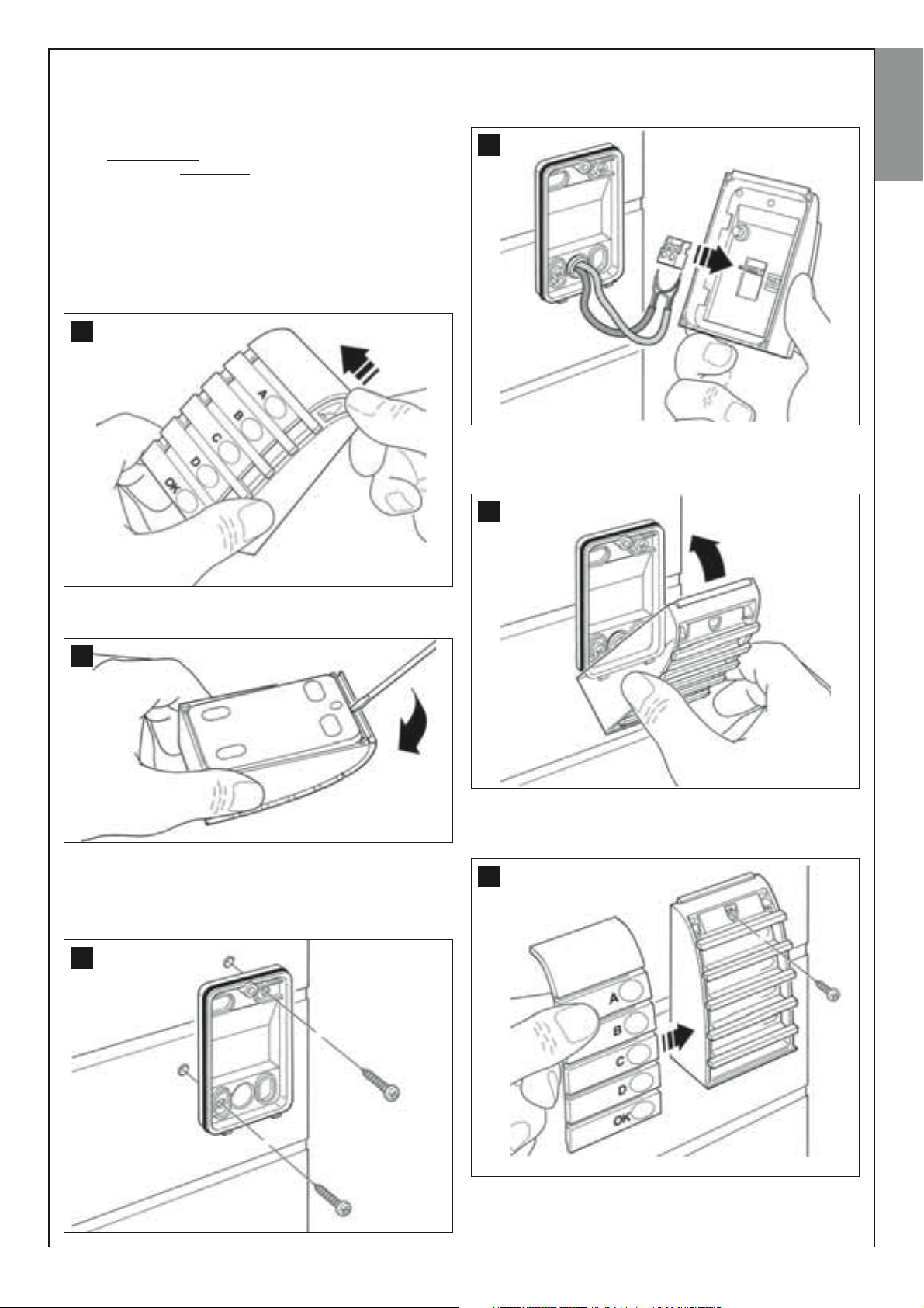
To install and connect the keypad proceed as follows:
01. Fig. 55:
Remove the keypad cover by pushing down one side as shown in
the figure.
) and safety mode (to activate a manoeuvre, a secret key
(each key performs a specifically assigned func-
55
04. Fig. 58:
a) Connect the cable wires to the respective terminals.
b) Insert the cable connector in the male connector at the rear of the
keypad.
58
05. Fig. 59:
Refit the cover, ensuring that the serrated section engages with that
of the keypad base.
59
English
02. Fig. 56:
Using a screwdriver, open and detach the base of the keypad.
56
03. Fig. 57:
a) Drill a hole on the pre-cut section on the base for routing the connection cables.
b) Fix the keypad base to the wall with the relative screws, routing
the cables through the prepared hole.
57
06. Fig. 60:
Fix the keypad cover to the base by means of the screw supplied.
Lastly refit the screw cover cap as shown in the figure.
60
English – 21
6.6 – INSTALLING THE BUFFER
BATTERY mod. MB
The buffer battery is self-charging with a voltage of 12V and power of
2100mAh. This is particularly useful in the event of a sudden power failure.
The gearmotor with control unit enables the installation of 1 battery.
English
Depending on the type and weight of the gate, when charged, the battery
guarantees an autonomy of approx. 6 - 7 consecutive movement cycles
(1 cycle =
The buffer battery compartment is below the control unit; to install, proceed as follows:
01. Using a Phillips screwdriver, loosen the cable clamp screws to
02. Fig. 61-62:
opening- closing
release the power cable and facilitate removal of the control unit from
its seat.
Press with one finger on the tab (1) locking the control unit and with
the other hand remove the control unit from its seat by pushing it forwards and upwards (2) at the same time to detach it from the guide.
).
61
04. Refit the control unit in its seat as follows:
a) position the control unit above the guide
b) then push it down and pull backwards until it clicks into place.
CAUTION! - The point below (05 – electrical connection of
the buffer battery to the control unit ) must only be performed after completing all installation and programming
phases, as the battery is an emergency power source.
05. Fig. 64:
Insert the battery connector in the male connector on the control
unit.
64
1
62
2
03. Fig. 63:
Insert the battery in the compartment below the control unit.
63
WARNINGS
To guarantee optimal lifetime of the buffer battery, the following warnings should be
observed:
The buffer battery is an emergency device: Therefore it should only be used moderately in the event of real necessity. Excessive and continuous use can lead to overheating of the elements, which over time may reduce the normal lifetime of the battery.
Never leave the automation powered exclusively by the buffer battery for periods
longer than a day: The elements may overheat excessively and impair lifetime of the
battery.
Therefore, if absent from the installation site of the automation for prolonged periods,
it is recommended to detach the buffer battery terminal connected to the control
unit.
• When the buffer battery is completely discharged, around 24 hours are required to
completely recharge.
• In the event of prolonged periods of disuse, the optional battery should be
removed and stored in a dry location to avoid the risk of leaks of harmful substances
–––––––––––––––––––
Battery disposal
CAUTION! – Even if discharged, the batteries can contain pollutant substances and therefore must NEVER be disposed of in common waste collection points. Dispose of according to separate waste collection methods as envisaged by current local standards.
22 – English

POWER SUPPLY CONNECTION
STEP 7
WARNINGS
• The PVC power supply cable supplied with the product is ideal for
internal installation; an insulated tube must be used to protect the
cables when installed outside, or the specific H07RN-F type cable
can be requested to replace this version if required.
• Final connection
the cable supplied must be performed by a skilled and qualified
electrician, in observance of local current safety standards and the
instructions in the section “
To perform the automation operation and programming tests, insert the
power plug of the control unit (supplied) in a mains socket (fig. 65). If
the socket is far from the automation, use a suitable extension lead.
of the automation to the mains or replacement of
Tasks reserved for qualified technicians
INITIAL START-UP AND ELECTRICAL CONNECTION CHECK
STEP 8
CAUTION!
be performed on live electrical circuits and therefore manoeuvres
may be hazardous! Therefore proceed with care.
– The following operations described in this manual will
65
English
”.
CAUTION! – If the red led does not flash as described above, disconnect the Control unit from the power supply and carefully check
all connections (refer also to the paragraph “What to do if....”).
After powering up the control unit (fig. 65), the red led and green led (fig.
66) emit a series of flashes.
At the end of this phase, the red led starts flashing at regular intervals.
This confirms correct operation of the control unit.
66
“L2” green led“L1” red led
Key “P1”
English – 23
PROGRAMMING THE AUTOMATION
WARNINGS for programming:
• Always read the procedure first and then perform the operations in
English
the correct sequence.
• In this manual the transmitter keys are identified by means of numbers.
To check the correspondence of numbers and the transmitter keys see
fig. 67.
67
T1
T3
T2
T4
STEP 9
9.1 – MEMORISING DEVICES CONNECTED BY MEANS OF
“BUS” CABLE AND LEAF TRAVEL LIMIT POSITIONS
“0” AND “ 1”
To program the control unit, perform the following operations in the specified sequence:
Note –– During this procedure, the user can exit the process at any time
(without saving the operations performed) by pressing “P1” once on the
control unit (fig. 66). In particular, from point 07 onwards, the user can
also exit the procedure by activation of a safety device (photocell or other...).
• light off =
photocells).
04.
(on control Photocells)
Activate this type of photocell (if fitted on the system), interrupting the
beam once only. Successful learning is confirmed by the flashing light
(1
flash
05.
(on the keypads)
Activate the keypads (if fitted on the system) by pressing a single key
on each one as required once only.
Successful learning is confirmed by 2
ted by the keypad and 1 flash of the flashing light, if fitted on the system.
06.
(on the Control unit)
Pres and hold the key “P1” on the Control unit for at least 5 seconds
until the green Led turns off. Then release the key.
07.
(on Gate)
Note – the manoeuvres that follow enable the control unit to automat-
ically memorise the positions of point“0”(total closing) and point“1
(total opening), as shown in fig. 69.
photocells installed incorrectly (check “Bus” connection of
) and the keypad (1
beep
), if fitted on the system.
beeps
at short intervals, emit-
69
Positions “0”
Position “1” Position “1”
”
01.
(on Gate)
Release the two gearmotors by means of the special release key (see
chapter “
TECHNICAL DOCUMENTATION) and manually move the two gate
leafs to the position shown in fig. 68. Then lock the two gearmotors
again.
Manually releasing or locking the gearmotor
68
(on the Control unit)
02.
Pres and hold the key “P1” on the Control unit for at least 5 seconds
until the green Led turns off and the red led illuminates (this remains lit
through to the end of the procedure). Then release the key and proceed as follows:
03.
(on safety Photocells)
Note – The time available for this check is unlimited.
Check correct operation of these types of photocells, ensuring that
the relative Led flashes slowly. Otherwise if it is lit or off, correct alignment between the photocells attempting to obtain a flashing frequency that is slow as possible (
the photocell alignment
• slow flashing light =
• light permanently lit =
ment);
the slower the flashing speed, the better
).
correct photocell alignment
incorrect alignment (revise photocell align-
;
” in the
At this point the Control unit automatically activates 3 manoeuvres,
also indicated by the flashing light:
1 - Closure of Leaf 2, followed by closure of Leaf 1.
2 - Opening of the two leafs.
3 - Closing of the two leafs.
At the end of the last manoeuvre, the red led turns off (=
completed)
CAUTION! – As soon as the first manoeuvre starts, check immediately that:
a - Leaf 2 moves before Leaf 1;
b - Leaf 2 moves in the Closing direction.
If the results of these checks do not conform to specifications, stop
the procedure immediately by pressing P1 on the control unit once.
Then solve problems
repeat the entire procedure 9.1.
Memorising other devices connected by Bus cable at a later
date
If in future the user decides to install and memorise other devices connected to the control unit by means of the Bus, and procedure 9.1 has
been completed previously, the new devices can be memorised using
the same procedure, starting from point 01 through to point 06. On completion, press P1 once on the control unit to complete the memorisation
process.
and then resumes flashing at regular intervals
“a”
and
“b”
with reference to STEP 6.1. Then
procedure
9.2 – MEMORISATION OF TRANSMITTER MOD. MT4
CAUTION! – Always
ations in the correct sequence without allowing more than 10 seconds
to pass between releasing one key and pressing the next.
To enable control of the automation with the transmitter, the keys must be
memorised in the control unit memory.
Memorisation enables the association of each key with the required com-
read the procedure first and then perform the oper-
24 – English
mand, selecting from the following:
1 = Step-Step: Corresponds to the sequence...
The first command activates
Stop...
ing, activates
moving activates
2 = Step-Open: Corresponds to the sequence...
-Open...
moving, activates
moving activates
3 = Partial open: Corresponding to total opening of one leaf only This
command is only activated if Leaf 2, the subordinate leaf, is completely
closed.
4 = Apartment block open: This command is used for apartment
blocks and envisages programming of all apartment block transmitters
with a single “apartment block opening” key. This command operates as
follows:
• if the command is sent while an
manoeuvre continues;
• if the command is sent while a
manoeuvre is interrupted and an
• if the command is sent when the gate is stationary and completely
open, the
Stop
; the third activates
Stop
and so on.
The first command activates
Stop
; the third activates
Open
and so on...
Closing
manoeuvre is started.
Opening
Closure
Opening
Opening
Closing
Opening
Note – Automatic closure of the
Open - Stop – Close -
; the next, with the leaf mov-
; the fourth with the leaf
Open - Stop – Close
; the next, with the leaf
Closure
; the fourth with the leaf
manoeuvre is in progress, the
manoeuvre is in progress, the
manoeuvre is started;
gate is also possible, by programming a pause time as required (see
chapter 10).
A single procedure memorises a single key of the transmitter; this can be
memorised both on the present control unit and on control units of other
automations. The control unit memory can memorise up to 150 keys.
For each key to be memorised, repeat the following procedure.
“SAFETY” MODE PROGRAMMING
01. Press and hold keys “A” and “B” simultaneously for a few seconds,
until the keypad emits a sequence of beeps that indicate start-up of
programming.
02. Using the keys enter the “
keypad); and then press “OK”.
If the code is correct the keypad emits a series of beeps; if incorrect a
single continuous tone is emitted.
03. Using the keys enter the
and then press “OK”.
The keypad emits a series of
04. From the list below, select the command to be programmed and on
the keypad press the key to be associated with the command followed by OK.
Step-Step command = key A
“Partial open” command = key B
Open command = key C
Close command = key D
Stop command = key OK
The keypad emits a series of beeps to indicate completion of programming.
PUK code
” (10-letter code supplied with the
personal password
beeps
.
(from 1 to 10-letters);
Modifying the Personal Password
To modify you personal password, repeat the entire “Safety mode” procedure, changing the existing password at point 03.
“TRADITIONAL” MODE PROGRAMMING
To program this mode, perform the “Safety mode programming” procedure, and at point 03 and 04 press “OK” only.
English
01. Select which transmitter key is to be memorised (for example:
Key
T3).
02. Decide on the command (from those listed below) to be associated
with the selected key (for example:
03. Press “P1” (on the Control unit) the same number of times as the
selected command number (
that the green led emits the same number of quick flashes (repeated
at regular intervals).
04. (within 10 seconds) Press and hold the transmitter key to be memo-
rised for at least 2 seconds (
If the memorisation procedure is successful, the green led emits 3 long
flashes (= memorisation OK).
Note – Before the 10 second interval elaps-
Command “2”).
in the example “2”, i.e. twice
in the example, key
T3).
) and check
es, the key of a NEW transmitter with the same command can be memorised (useful, for example, when several transmitters need to be memorised on the same control unit).
Otherwise wait until the green led turns off (= procedure completed) and
for the red led to resume flashing at regular intervals.
9.3 – PROGRAMMING KEYPAD mod. MK
The control keypad can be programmed for two alternative operating
modes:
- TRADITIONAL mode
- SAFETY mode (with use of a personal password)
After memorisation (
(
factory setting
) but this may be modified as described below.
“Traditional” operating mode”
In this mode the keys are independent and each commands a specific
action. The commands are:
Key “A” = Step-step command
Key “B” = “Partial open” command
Key “C” = Open Command
Key “D” = Close command
Key “OK” = Stop Command
(without the use of a personal password)
see STEP
9.1) the keypad is set to “Traditional mode”
“Safety” operating mode”
In this mode the keypad is enabled on entry of a password set by the user
(from 1 to 10 letters) followed by the key OK. This combination of keys
only sends the specific command that the user set during the mode programming phase.
Note - If the Step-Step command is programmed, after the command is
sent the user has 10 seconds in which to send a subsequent command,
by simply pressing “OK”. This eliminates the need to repeat password
entry.
English – 25
ADJUSTMENTS AND OTHER OPTIONAL FUNCTIONS
The control unit has a number of optional functions to enable the user to
add specific functionalities to the automation, thus personalising the product according to special needs.
English
10 – AUTOMATION OPERATION ADJUSTMENT
To personalise operation of the automation, a number of functions can be
enabled or disabled, also with the option for modifications to settings as
required. The functions are:
• AUTOMATIC LEAF CLOSURE When this function is enabled, at the
end of an Opening manoeuvre activated by the client, the control unit
automatically closes the gate after a set time interval.
• LEAF MOVEMENT SPEED This function enables the user to set the
required speed used by the automation to move the gate leafs.
• LEAF SENSITIVITY TO OBSTACLES During a manoeuvre, if an obsta-
cle accidentally stops gate leaf movement (a gust of wind, a vehicle, person etc.) this function promptly detects the increase in motor stress to
contract the obstacle and activates immediate and total inversion of
movement. If “automatic leaf closure” is set, the control unit re-attempts
the movement a second time and on the third time, after a brief inversion,
it stops the manoeuvre permanently.
• LEAF PRESSURE DISCHARGE At the end of the Closing manoeuvre,
after the leafs have reached limit switch “0”, the motor continues to
“push” the leafs for a brief interval, to ensure perfect closure. Immediately
afterwards, this function activates a very brief inversion of movement, to
reduce excessive pressure exerted by the motor on the leafs
The values of these functions can be set according to personal requirements using the following procedure with a transmitter that has at least
one key already memorised on the control unit.
Note – During this procedure, each time a key is pressed the flashing light
emits one flash.
TABLE 4
Automatic leaf closure
No closure —> (press key “T1”)
Closure after 15 seconds —> (press key “T2”)
Closure after 30 seconds —> (press key “T3”)
Closure after 60 seconds —> (press key “T4”)
Leaf movement speed
Low —> (press key “T1”)
Medium low —> (press key “T2”)
Medium high —> (press key “T3”)
High —> (press key “T4”)
Leaf sensitivity to obstacles
High —> (press key “T1”)
Medium high —> (press key “T2”)
Medium low —> (press key “T3”)
Low —> (press key “T4”)
Leaf pressure discharge
No discharge —> (press key “T1”)(*)
Minimum —> (press key “T2”)
Medium —> (press key “T3”)
Maximum —> (press key “T4”)
01. Press and hold the keys “T1” and “T2” simultaneously on the trans-
mitter for at least 5 seconds, after which release.
The two leds (green and red) on the Control unit flash to indicate entry
to function programming mode (
the procedure
02. Press and hold a transmitter key (already memorised on that of the
control unit) for at least 1 second (
03. Then select one of the four functions available and on the transmitter
press the key associated with the function for at least 1 second (
green Led emits one flash
• Automatic leaf closure = (press key “T1”)
• Leaf movement speed = (press key “T2”)
• Leaf sensitivity to obstacles = (press key “T3”)
• Leaf pressure discharge (= press key “T3”)
04. Lastly, refer to Table 4, select the required value in correspondence
with the selected function and on the transmitter press the key associated with the selected value for at least 1 second (the
red Leds emit one confirmation flash
).
the leds continue to flash throughout
the green Led emits one flash
):
).
).
the
green and
Notes to Table 4:
– (*) It is not recommended to set this value AT ANY TIME.
– The Table states the values available for each of the 4 special functions
and the corresponding key to be pressed on the transmitter for selection
of the specific value.
– The factory settings are highlighted in grey.
– When power is restored after a power failure the first manoeuvre com-
mand will be run at low speed, regardless of the type of speed setting.
11 – MEMORISING A NEW TRANSMITTER WITH PROCE-
DURE IN THE VICINITY OF THE CONTROL UNIT
[with a transmitter already memorised]
A NEW transmitter can be memorised in the control unit memory without
acting directly on key P1 of the control unit, but by simply working within
its reception range. To use this procedure, an OLD transmitter, previously
memorised and operative, is required. The procedure enables the NEW
transmitter to receive the settings of the OLD version.
Warning – The procedure must be performed within the reception
range of the receiver (maximum 10-20 m from receiver).
01. On the NEW transmitter, press and hold the key to be memorised for
at least 5 seconds and then release.
02. On the OLD transmitter, slowly press the control key to be memo-
rised on the other transmitter 3 times.
03. On the NEW transmitter, press the same key pressed in point 01
once.
26 – English
Note – Repeat the same procedure for each key to be memorised.
12 – DELETING DATA FROM THE CONTROL UNIT MEMORY
Data in the control unit memory can be deleted partially or totally as
required. To do this, the following procedures can be used, as required:
•Deletion of a command on a transmitter already memorised
•Deletion of other data memorised on the control unit
English
on a transmitter already memorised
The following procedure enables deletion of a single command assigned
to a transmitter key from the control unit memory.
Note – During the procedure, the red and green leds remain permanently lit.
01. Pres and hold the key “P1” on the Control unit for at least 10 sec-
onds: the green Led illuminates first, then the red led illuminates after
5 seconds and then both, to indicate that the Control unit has entered
memory deletion mode (WARNING! – do not release the key P1!).
02. Without releasing key P1
the control unit recognises this operation, the green led emits a short
flash, after which the P1 key and transmitter key can be released.
The following procedure enables deletion of various types of memorised
data from the control unit memory, as specified in Table 5.
Note – During the procedure, the red and green leds remain permanently lit.
01. Pres and hold the key “P1” on the Control unit for at least 10 sec-
onds: the green Led illuminates first, then the red led illuminates after
5 seconds and then both, to indicate that the Control unit has entered
memory deletion mode. Then release the key.
02. With reference to Tabl e 5, select the data to be deleted and press P1
the same number of times as the number of presses specified in
brackets (the green led emits one flash each time the P1 key is
pressed).
03. 5 seconds after the key “P1” is pressed for the last time, if deletion is
successful, both leds (red and green) flash quickly
Note – Before deletion, there is a margin time of 5 seconds, in which
the user has the option to change decision and exit the procedure
without deleting data by pressing key P1 five times.
Deleting a command
press the transmitter key to be deleted: if
Deleting other
data memorised on the control unit
(= memory deleted!)
.
IMPORTANT! – After deletion of the “Memory of positions 0 and 1” and
“TOTAL Memory”, the procedure 9.1 – “Memorising devices connected
by means of Bus cable and leaf travel limit positions 0 and 1” must be
repeated.
TABLE 5
• Memory of Optional Function values (= 1 press)
• Memory of positions “0” and “1” (= 2 presses)
• Memory of Transmitters (= 3 presses)
• TOTAL memory (= 4 presses).
memories in one process
Note – deletes the first three
English – 27
Tasks reserved for qualified technicians
English
CAUTION! –
personnel, in observance of the instructions in the manual, and current local legislation and
safety standards in the place of installation.
All operations in this section must be performed exclusively by skilled and qualified
CONNECTING THE AUTOMATION TO THE ELECTRICAL MAINS
USING A CABLE OTHER THAN THE VERSION SUPPLIED
CAUTION! – Strictly observe the electrical connections specified in
this paragraph, as incorrect connections could lead to serious faults
or hazards.
If the distance of the gate from the electrical mains is greater than the
length of the power cable supplied, this cable may be replaced with an
electric line that is adequately protected and suited to the application.
In this case, use a power cable with the dimensions 3 x 1,5 mm2, and
maximum length of 30 m. For greater lengths, use a cable with a larger
section: For example , 3 x 2,5 mm2, ensuring safety earthing in the vicinity of the automation. Then proceed as follows:
To connect the new cable to the Control unit:
01. Fig. A:
a) Loosen the screw on the top of the cover using a Phillips screwdriver.
b) Place two fingers on the two cavities on the rear of the germotor
and lift the cover by pulling upwards, using the base as leverage.
A
from its seat to facilitate wiring.
– Brown wire, to connect to “Phase”
– Blue wire, to connect to “Neutral”
– Yellow-green wire, to connect to “Earth”
B
1
2
C
02. Fig. B and C – Using a Phillips screwdriver loosen the screws of the
terminal board cover (fig.B-1) and the cable clamp (fig. B-2) to
release the power cable to be replaced, and eliminate. Then fit the
new power cable through the hole on the lower side of the gearmotor and connect the cable wires to the terminal board, taking care to
observe the symbols.
To connect the new cable to the electrical mains:
Caution! – When making this connection, the electrical mains power line must be equipped with short-circuit protection device (between the automa-
tion and the mains).
The electrical mains line must also be equipped with a power disconnect device (with overvoltage category III, i.e. minimum gap between contacts of
3.5 mm) or an equivalent system such as socket with removable plug.
This device, when necessary, guarantees fast and safe disconnection of the power supply and therefore must be placed in a location visible from the
automation. If the power disconnect device is not in the vicinity of the automation and not visible from the latter, it must be fitted with a lockout facility
to prevent inadvertent or unauthorised connection.
Note – The disconnect devices are not supplied with the product.
Note – the terminal board can be removed
03. Then refit the terminal board cover, cable clamp and close the gearmotor with its cover.
28 – English
AUTOMATION TESTING AND COMMISSIONING
These are the most important phases of automation set-up to ensure maximum system safety.
The testing procedure described can also be performed as a periodic check of automation devices.
Testing and commissioning of the automation must be performed by skilled and qualified personnel, who are responsible for the tests required to verify the solutions adopted according to the risks present, and for ensuring observance of all legal provisions, standards and regulations , and in particular all requirements of the standard EN 12445, which establishes the test methods for checking automations for doors and gates.
English
AUTOMATION TESTING
1 Ensure that all specifications in STEP 1 regarding safety have been
strictly observed.
2 Using the transmitter, perform door opening and closing tests and
ensure that the movement corresponds to specifications.
Test several times to assess smooth operation of the door and check
for any defects in assembly or adjustment and any possible points of
friction.
3 Check operation of all system safety devices one at a time (photocells,
sensitive edges, etc.) Photocells: Activate the device during an
or
Closing
manoeuvre and activates a total inversion of the movement (the flashing
light emits 2 flashes, twice). Sensitive edges: Activate the device during
an
Opening
the manoeuvre and activates a short inversion of the movement (the
flashing light emits 4 flashes, twice).
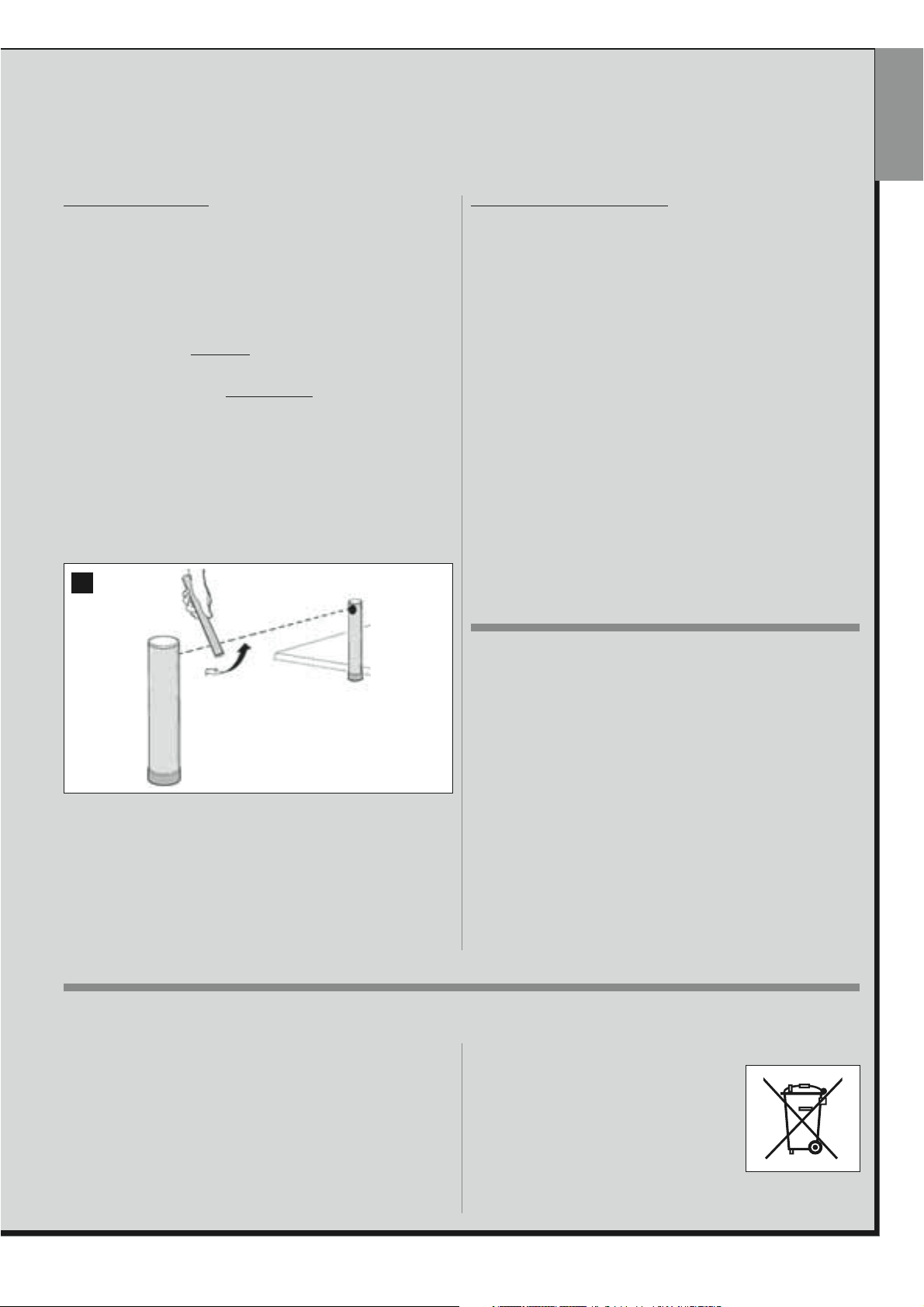
4 To check the photocells, and to ensure there is no interference with
other devices, pass a cylinder (diameter 5 cm, length 30 cm) through
the optic axis joining the pair of photocells (fig. 70): pass the cylinder
first close to the TX photocell, then close to the RX and lastly at the
centre between the two. Ensure that in all cases the device engages,
changing from the active status to alarm status and vice versa, and that
the envisaged action is generated in the control unit (for example movement inversion in the Closing manoeuvre).
manoeuvre and check that the control unit stops the
or
Closing
manoeuvre and check that the control unit stops
Opening
70
AUTOMATION COMMISSIONING
Commissioning can only be performed after positive results of all
test phases. Partial or “makeshift” commissioning is strictly prohibited.
1 Prepare the automation technical documentation, which must contain
the following documents: Overall layout drawing (see example in fig. 8),
electrical wiring diagram (see example in fig. 26), risk assessment and
relative solutions adopted (see forms to be compiled on the website
www.moovo.com, manufacturer’s declaration of conformity for all
devices used and the declaration of conformity compiled by the
installer (see section TECHNICAL DOCUMENTATION).
2 Affix a dataplate on the door, specifying at least the following data: type
of automation, name and address of manufacturer (responsible for
commissioning), serial number, year of construction and CE mark.
3 Prepare and provide the owner with the declaration of conformity; the
“CE Declaration of conformity”
MENTATION must be compiled for this purpose.
4 Prepare and provide the owner with the form
the section TECHNICAL DOCUMENTATION .
5 Prepare and provide the owner with the form
in the section TECHNICAL DOCUMENTATION, containing all maintenance instructions for all devices in the automation .
6 Before commissioning the automation, ensure that the owner is ade-
quately informed of all associated risks and hazards.
in the section TECHNICAL DOCU-
“Operation manual”
“Maintenance schedule”
in
5 Measure the force as specified in the standard EN 12445. If the motor
force control is used as an auxiliary function for reduction of impact
force, test and identify the setting that obtains the best results.
6 Activate a closing manoeuvre and check impact force of the leaf
against the mechanical stop. If necessary, test by discharging pressure
to obtain the best results.
PRODUCT DISPOSAL
This product is an integral part of the automation and therefore must
be disposed together with the latter.
As in installation, also at the end of product lifetime, the disassembly and
scrapping operations must be performed by qualified personnel.
This product comprises various types of materials: some may be recycled
others must be disposed of. Seek information on the recycling and disposal systems envisaged by the local regulations in your area for this
product category.
CAUTION! – some parts of the product may contain pollutant or hazardous substances which, if disposed of into the environment, may cause
serious damage to the environment or physical health.
PERIODIC MAINTENANCE OPERATIONS
This product does not generally require any special maintenance; nevertheless, regular check-ups are advisable to ensure the system is in good
working order and that the safety devices installed work properly.
To carry out this maintenance correctly, please refer to the
Schedule”
section at the end of the manual.
As indicated by the symbol alongside, disposal of this product in domestic waste is strictly prohibited Separate the waste
into categories for disposal, according to the
methods envisaged by current legislation in your
area, or return the product to the retailer when purchasing a new version.
CAUTION! – Local legislation may envisage serious fines in the event of abusive disposal of this
product.
, which you will find in the “TECHNICAL DOCUMENTATION”
“Maintenance
English – 29
TECHNICAL SPECIFICATIONS OF PRODUCT COMPONENTS
WARNINGS
– The product XA4... is produced by Nice S.p.a. (TV) I. Moovo is a commercial trademark owned by Nice S.p.a.
– All technical specifications stated in this section refer to an ambient temperature of 20°C (± 5°C).
English
– Nice S.p.a. reserves the right to apply modifications to the product at any time when deemed necessary, while maintaining the same functionalities and intended use
GEARMOTORS XA4...
Note – The model XA432e houses the control unit.
DESCRIPTION DATA
Mod. XA432 Mod. XA432e
Power supply (Vac)
Maximum absorbed power (W)
of the motor
Maximum thrust 150 N
Nominal thrust 70 N
Speed under no load
Nominal speed 3° / sec 6° / sec 3° / sec 6° / sec
Cycles/h at nominal thrust (20°) 8
Cycle frequency
maximum continuous
Operating temp. - 20 / + 50° C
Dimensions 253 x 155 h x 235 mm
Weight 6.2 kg 6.3 kg
Protection class IP 44
Estimated durability (*) from 50.000 to 100.000 manoeuvre cycles
low high low high
4.5° / sec 9° / sec 4.5° / sec 9° / sec
12 Vdc 230 Vac - 50/60 Hz
250 W
5
(*) Note – The estimated product durability ranges from 50.000 to
100.000 manoeuvre cycles. To calculate the probable durability of your
automation proceed as follows:
a) – evaluate the conditions of use and force levels involved on your system, for example:
• the weight and length of the leaf;
• perfect balancing of the leaf;
• maintenance conditions of the leaf hinges;
• type of leaf; Solid or with many openings;
• the presence of strong winds;
• frequency of automation use.
b) – from these values, obtain a value expressed as a percentage which,
in general, defines the greatest or smallest degree of automation wear.
c) – on the graph alongside, locate the estimated percentage (at point
"b") and read the corresponding number of manoeuvre cycles.
100 %
75 %
50 %
25 %
0 %
50.000
60.000
70.000
80.000
90.000
MF FLASHING LIGHT
DESCRIPTION DATA
Type Flashing light for automations on gates and doors
Technology adopted Luminous indicator with lamp controlled by Moovo control units with “Bus” system for automation
Lamp 12V 21W fitting BA15 (car type lamp)
Power supply The device must be connected to the “Bus” terminal of the Moovo control units for automations
Ambient operating temperature -20 ÷ 50°C
Use in acid, saline or potentially
explosive atmospheres
Assembly Vertical on surface or horizontal wall-mounted
Protection class IP 44
Dimensions 135 x 120 h x 110 mm
Weight 340 g
No
100.000
30 – English
 Loading...