

Moovo TS4 User Manual
Garage door opener
TS4...
EN Installation and use instruc-
tions and warnings
IT Istruzioni ed avvertenze
per l’installazione e l’uso
FR Instructions et avertisse-
ments pour l’installation et
l’utilisation
ES Instrucciones y adverten-
cias para la instalación y
el uso
DE Anweisungen und Hinweise
für die Installation und die
Bedienung
PL Instrukcje instalacji i
użytkowania i ostrzeżenia
NL Aanwijzingen en aanbeve-
lingen voor installering en
gebruik
Codice: ISTGDX.4865 - Rev. 03 del 20 - 06 - 2007

CONTENTS
GENERAL SAFETY WARNINGS AND
PRECAUTIONS
STEP 1
– Working in safety! 4
– Installation warnings 4
KNOWLEDGE OF THE PRODUCT AND PREPARATION
FOR INSTALLATION
STEP 2
2.1 - Product description and intended use 5
2.2 - Components used to set up a complete system 5
STEP 3
Preliminary checks for installation 6
3.1 - Checking suitability of the environment and door to be automated 6
3.2 - Checking product application limits 6
STEP 4
4.1 - Preliminary set-up work 7
- 4.1.1 - Typical reference system 7
- 4.1.2 - Establishing positions of components 7
- 4.1.3 - Establishing the device connection layout 7
- 4.1.4 - Checking the tools required for the work 7
- 4.1.5 - Completing the set-up work 7
4.2 - Laying the electric cables 7
WHAT TO DO IF... (troubleshooting guide) 21
TASKS RESERVED FOR QUALIFIED TECHNICIANS
– Connecting the automation to the electrical mains 22
– Automation testing and commissioning 22
– Product disposal 23
TECHNICAL SPECIFICATIONS OF
COMPONENTS 24
Enclosures: “TECHNICAL DOCUMENTATION” I-VII
English
INSTALLATION: COMPONENT ASSEMBLY AND
CONNECTION
STEP 5
5.1 - Installing the automation components 10
5.2 - Installing buffer battery mod. ME 12
5.3 - Fixing the automation to the wall, ceiling, and door 13
STEP 6
– System device installation and connection 15
POWER SUPPLY CONNECTION
STEP 7 17
INITIAL START-UP AND ELECTRICAL CONNECTIONS
CHECK
STEP 8 17
PROGRAMMING THE AUTOMATION
STEP 9
9.1 - Memorisation of transmitter mod. MT4 18
9.2 - Memorising the door “Opening” and “Closing” travel limit positions 18
DJUSTMENTS AND OTHER OPTIONAL FUNCTIONS
10 - Automation operation adjustment 19
11 - Memorisation of a new transmitter with control unit “in the vicinity” 19
12 - Deleting data from the Control unit memory 19
English – 3
GENERAL SAFETY WARNINGS AND PRECAUTIONS
STEP 1
English
WORKING IN SAFETY!
Please note - These instructions must be followed to
guarantee personal safety.
Please note – Important safety instructions. Keep for
future reference.
The design and manufacture of the devices making up the product
and the information in this manual fully comply with current standards governing safety. However, incorrect installation or programming may cause serious physical injury to those working on or using
the system. For this reason, during installation, always strictly
observe all instructions in this manual.
If in any doubt regarding installation, do not proceed and contact the
Moovo Technical Assistance for clarifications.
If this is the first time you are setting up an automation for garage doors
(sectional or up-and-over), we recommend that you read this entire manual with care. This is preferable before any work, without any hurry to start
practical tasks.
Also keep product devices on hand while consulting the manual to enable
testing and checking (excluding any programming phases) with the information provided in the manual.
While reading this manual, take care to observe all instructions
marked with the following symbol:
These symbols indicate subjects that may be the source of potential
hazards and therefore the prescribed operations must be performed
exclusively by qualified and skilled personnel, in observance of
these instructions current safety standards.
Technical documentation. This must be compiled by a professional
installer.
Considering the risk situations that may arise during installation
phases and use of the product, the automation must be installed in
observance of the following warnings:
– never make any modifications to part of the automation other than those
specified in this manual. Operations of this type will lead to malfunctions.
The manufacturer declines all liability for damage caused by makeshift
modifications to the product.
– ensure that parts of the automation cannot come into contact with
water or other liquids. During installation ensure that no liquids penetrate
the gearmotors or other devices present.
– Should this occur, disconnect the power supply immediately and contact a Moovo service centre. Use of the automation in these conditions
constitutes a hazard.
– never place automation components near to sources of heat and never
expose to naked flames. This may damage system components and
cause malfunctions, fire or hazardous situations.
– all operations requiring opening of the protection housings of various
automation components must be performed with the control unit disconnected from the power supply. If the disconnect device is not in a visible
location, affix a notice stating: “WARNING! MAINTENANCE IN
PROGRESS”.
– the product may not be considered an efficient system of protection
against intrusion.
If an efficient protection system is required, the automation must be inte-
grated with other devices.
– Connect the control unit to an electric power line equipped with an
earthing system.
– the product may only be used after completing the automation “com-
missioning” procedure as specified in paragraph “Automation testing
and commissioning” provided in the section “Tasks reserved for qualified
technicians”.
– The automation component packaging material must be disposed of in
full observance of current local legislation governing waste disposal.
INSTALLATION WARNINGS
According to the most recent legislation, the installation of a garage
door must be in full observance of the standards envisaged by European Directive 98/37/EC (Machinery Directive) and in particular standards EN 12445, EN 12453 EN 12635 and EN 13241-1, which enable
declaration of presumed conformity of the automation.
The final connection of the automation to the electrical mains, system testing, commissioning and periodic maintenance must be performed by skilled and qualified personnel, in observance of the
instructions in the section “Tasks reserved for qualified technicians”.
These personnel are also responsible for the tests required according to the risks present, and for ensuring observance of all legal provisions, standards and regulations , and in particular all requirements
of the standard EN 12445, which establishes the test methods for
checking automations for garage doors.
However, all preliminary set-up, installation and programming operations may be performed by personnel with standard skills, provided
that all instructions and the relative sequences in this manual are
strictly observed, with special reference to the warnings in STEP 1.
Before starting installation, perform the following checks and
assessments:
– ensure that each device used to set up the automation is suited to the
intended system. For this purpose, pay special attention to the data provided in the paragraph “Technical specifications”. Do not proceed with
installation if any one of these devices does not correspond to specifications.
– ensure that the devices in the kit are sufficient to guarantee system safety and functionality.
– an assessment of the associated risks must be made, including a list of
the essential safety requirements as envisaged in Appendix I of the
Machinery Directive, specifying the relative solutions adopted. Note that
the risk assessment is one of the documents included in the automation
In consideration of the above,
4 – English
KNOWLEDGE OF THE PRODUCT AND PREPARATION FOR INSTALLATION
STEP 2
2.1 – PRODUCT DESCRIPTION AND INTENDED USE
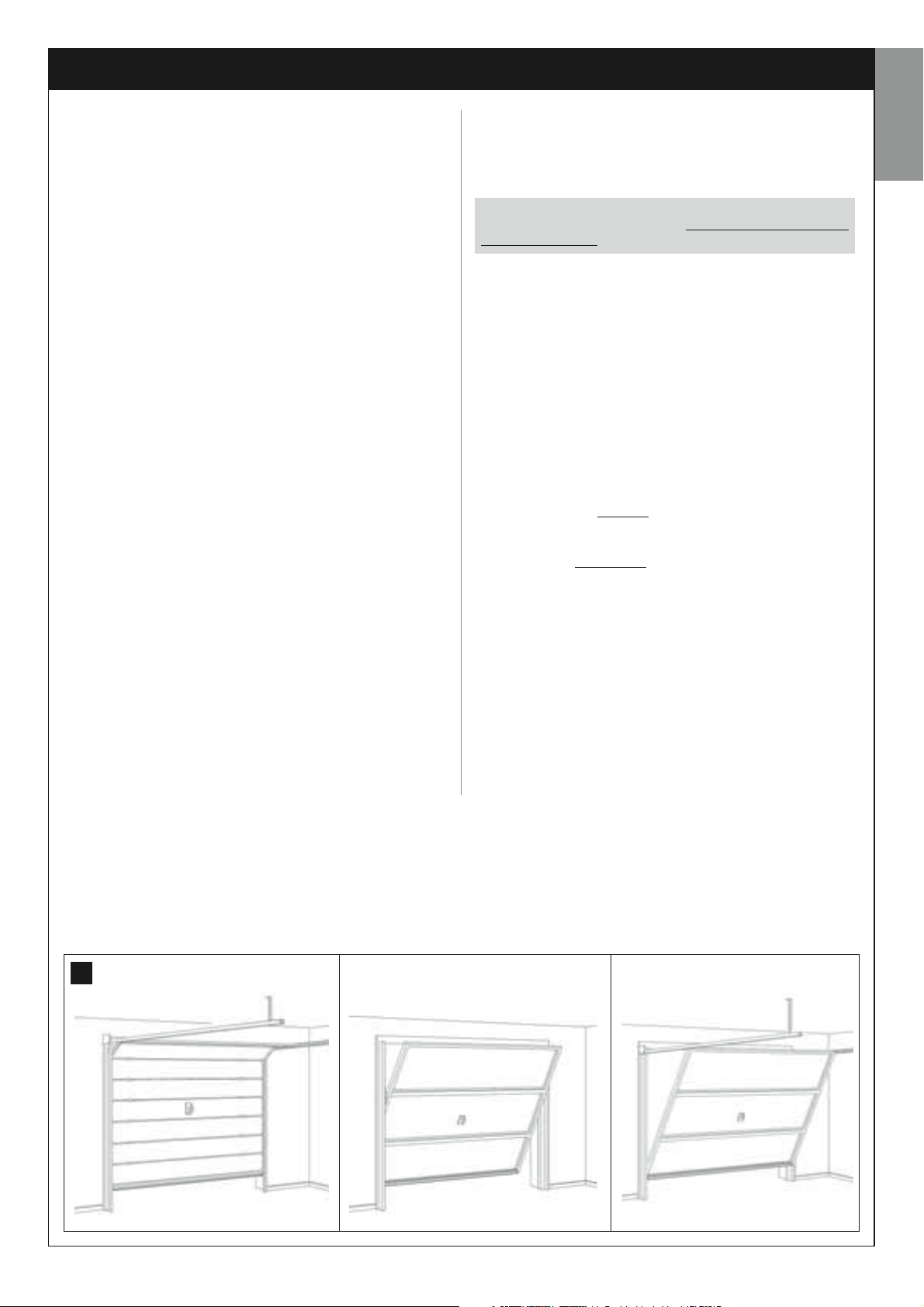
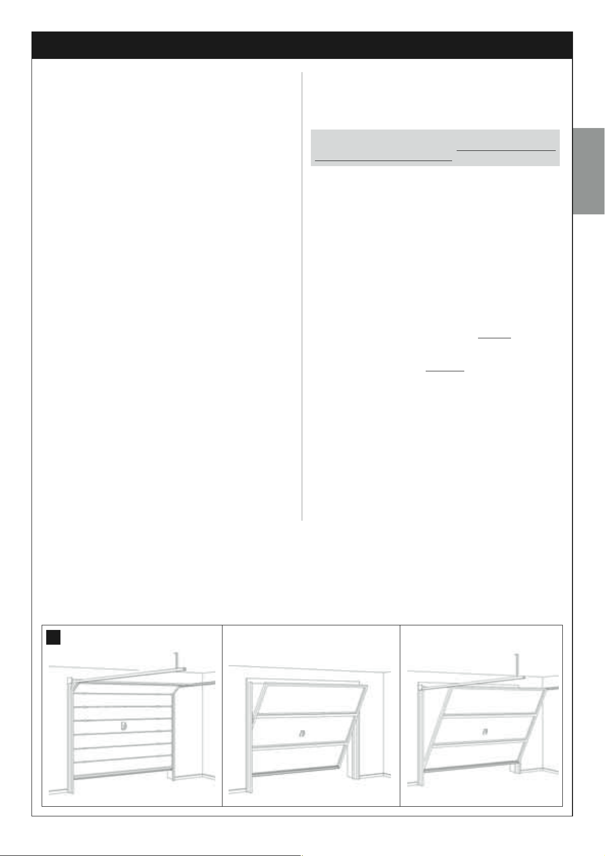
In general, the series of devices that make up this product serve to automate a garage door for residential applications (fig. 1). This type may be
“sectional” or “up-and-over”; up-and-over doors may be projecting (during opening the door protrudes outwards) or non-projecting with springs
or counterweights.
In particular, this kit is designed for the automation exclusively of sectional
garage doors. Therefore, to automate an up-and-over door, the special
oscillating arm must be fitted (mod. MA, not supplied in pack).
Any other use than as specified herein or in environmental conditions other than as stated in STEP 3 is to be considered improper
and is strictly prohibited!
This product (TS432B - TS432Be - TS432BH - TS432BeH) comprises
an electromechanical gearmotor with a 24 V dc motor, a guide, chain and
a drive carriage. The gearmotor is also equipped with a control unit.
The control unit comprises an electronic board, a courtesy/indicator light
and a built-in radio receiver, plus an aerial, which receives the commands
sent by a transmitter.
The control unit can control different types of manoeuvres, each programmable and usable according to specific requirements.
Special functions are also available to enable personalisation of automation operation.
The automation is designed for use with various accessories which
enhance functionality and guarantee optimal safety. More specifically, the
control unit can memorise up to 150 keys of transmitters mod. MT4 and
up to 4 pairs of photocells, mod. MPQ.
The product is mains-powered, and, in the event of a power failure
enables manual movement of the door, by release of the drive carriage
using a special cord or by means of a release mechanism located externally (mod. MU, not supplied in pack).
In any event the door can also be opened by means of a buffer battery
(mod. ME, not supplied in pack) if fitted on the system.
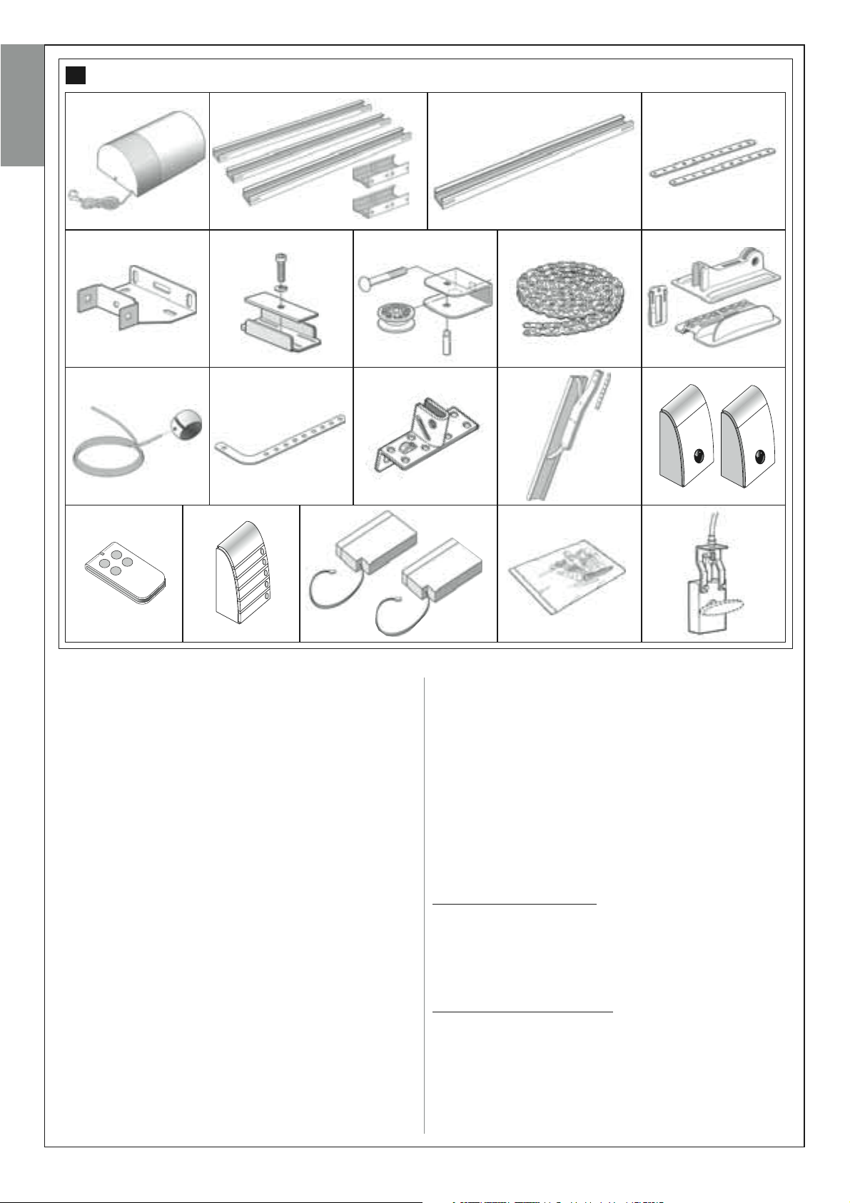
2.2 – COMPONENTS USED TO SET UP A
COMPLETE SYSTEM
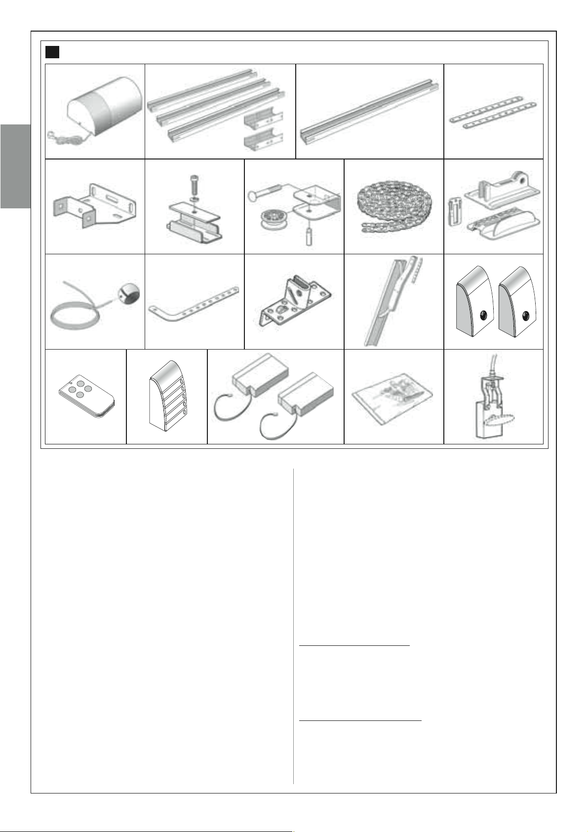
Fig. 2 illustrates all components used to set up a complete system, such
as that shown in fig. 8.
Some components shown in fig. 2 are optional and may not be
supplied in the pack.
List of components:
[a] - electromechanical gearmotor
[b] - guide for carriage in 3 parts + joining brackets
(only for mod. TS432B and TS432Be)
[c] - integral guide (only for mod. TS432BH and TS432BeH)
[d] - gearmotor ceiling mounting brackets
[e] - gearmotor wall-mounting brackets
[f] - mechanical stop for carriage travel limit
[g] - chain gear
[h] - drive chain
[i] - drive carriage
[l] - automation release knob and cord
[m]- door drive rod (for sectional
[n] - bracket for connection of drive rod to door
[o] - oscillating arm and relative drive rod
(mod. MA, for up-and-over
[p] - pair of photocells (wall-mounted) mod. MPQ
[q] - transmitter (portable) mod. MT4
[r] - radio control keypad mod. MKR (wall-mounted)
[s] - two buffer batteries mod. ME
(only for mod. TS432BH and TS432BeH)
[t] - Metal hardware (screws, washers, etc.)
[u] - external release kit mod. MU
WARNING!
doors only)
doors only)
*
English
(
) Note – The screws required for wall-fixture of components are not
*
included in the pack, as their type depends on the material and thickness
of the door in which they are inserted.
1
SECTIONAL PROJECTING NON-PROJECTING
English – 5
2
ab c d
English
ef ghi
lmnop
qr s t
STEP 3
PRELIMINARY INSTALLATION WORK
Before proceeding with installation, check the condition of the product
components, suitability of the selected model and conditions of the
intended installation environment.
IMPORTANT – The gearmotor
that is not fully efficient and safe
caused by poor installation or insufficient maintenance of the
door itself.
3.1 – CHECKING SUITABILITY OF THE ENVIRONMENT
AND THE DOOR TO BE AUTOMATED
• In the case of automating a projecting up-and-over door, ensure that
movement does not obstruct public roads or pavements.
• Ensure that the mechanical structure of the door is suitable for automa-
tion and complies with local standards.
• Check stability of the mechanical structure of the door, ensuring that
there is no risk of guides coming out of their seats.
• Move the door manually to open and close, checking that movement
has the same degree of friction throughout all points of travel (no increase
in friction must occur).
• Ensure that the door is correctly balanced: in other words, if left station-
ary (manually) it must not move from any position.
• Ensure that the space around the automation enables safe and easy
manual release.
• Ensure that the selected surfaces for installation of the various devices
cannot be used to power a door
. Neither can it solve defects
are solid and guarantee a stable fixture.
• Ensure that all devices to be installed are in a sheltered location and protected against the risk of accidental impact.
• Ensure that the selected surfaces for fixing the photocells are flat and
enable correct alignment between photocells.
3.2 – CHECKING PRODUCT APPLICATION LIMITS
To ascertain suitability of the product with respect to the specific features
of the door and area to be automated, the following checks should be
performed as well as a check for compliance of the technical data in this
paragraph and the chapter “Product technical specifications”.
• Ensure that the dimensions and weight of the door are within the following limits of use:
model TS432B and TS432Be
– Sectional doors: maximum width 350 cm; maximum height 212 cm;
maximum movement force 500 N.
– Projecting up-and-over doors: maximum width 350 cm; maximum
height 260 cm; maximum movement force 500 N.
– Non-projecting up-and-over doors: maximum width 350 cm; maxi-
mum height 212 cm; maximum movement force 500 N.
model TS432BH and TS432BeH
– Sectional doors: maximum width 350 cm; maximum height 240 cm;
maximum movement force 500 N.
– Projecting up-and-over doors: maximum width 350 cm; maximum
height 280 cm; maximum movement force 500 N.
– Non-projecting up-and-over doors: maximum width 350 cm; maximum height 220 cm; maximum movement force 500 N.
Note – The shape of the door and weather conditions, such as the pres-
ence of strong winds, can reduce the above maximum values. In these
u
6 – English
cases it is important to measure the force required to move the door in the
worst conditions and compare these with the technical specifications of
the gearmotor.
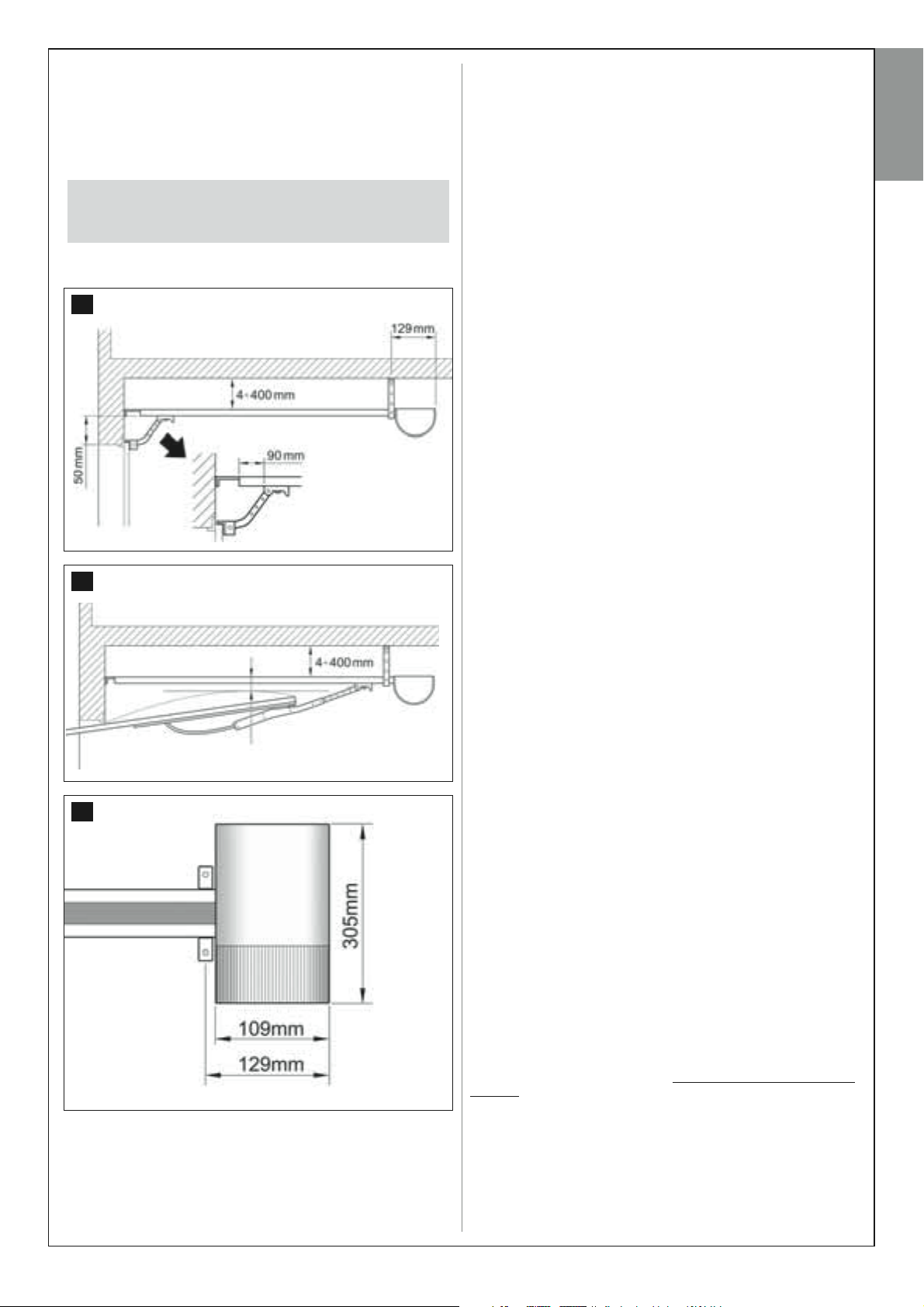
• Ensure that the area for mounting the gearmotor and guide is compati-
ble with the overall dimensions of the automation to be installed. Then
ensure that the minimum and maximum clearances can be observed as
shown in fig. 3, 4 and 5.
Caution! – If the results of these checks do not conform to specifications, this model cannot be used to automate your door.
3
D
B
STEP 4
4.1 – PRELIMINARY SET-UP WORK
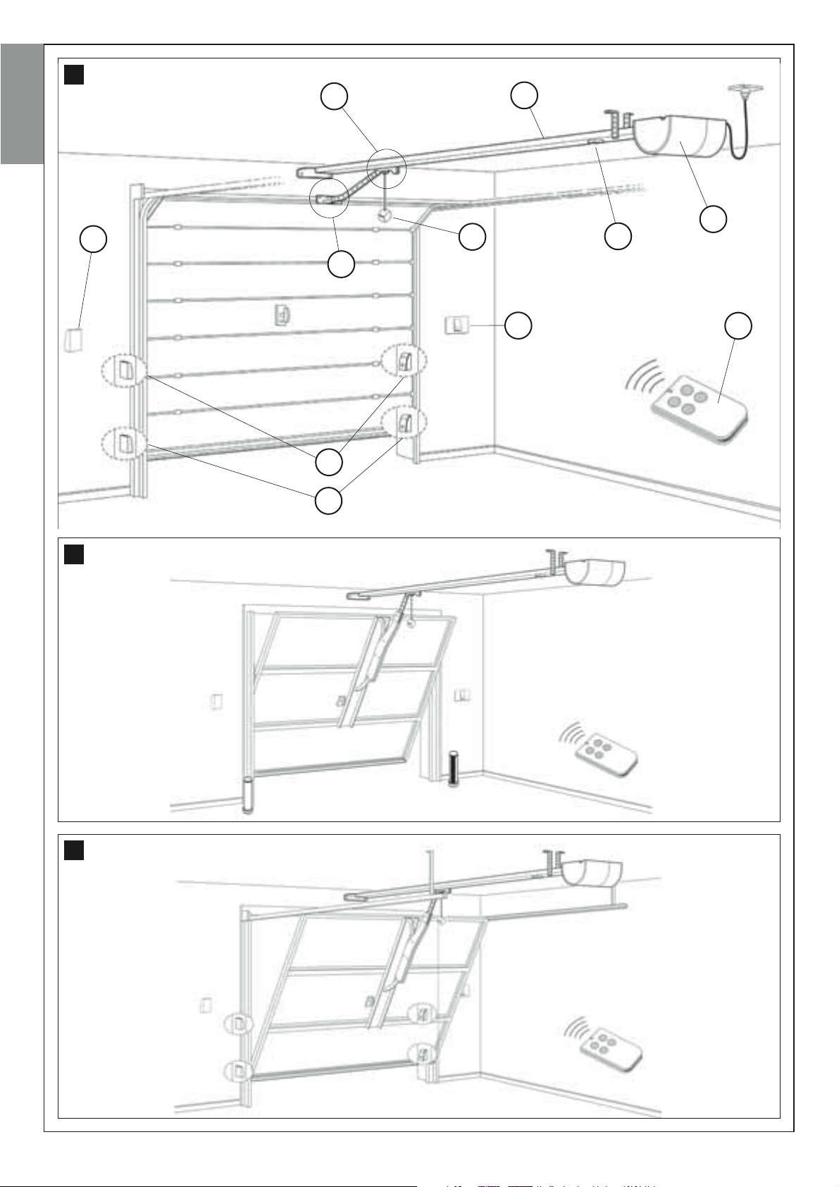
4.1.1 – Typical reference system
Fig. 6, 7, 8 provide an example of an automation system set up with the
components compatible with this product. These parts are positioned
according to a typical standard layout. The following components are
used:
a - Electromechanical gearmotor
b - Carriage sliding guide
c - drive carriage
d - mechanical stop for carriage travel limit
e - carriage manual release knob
f - bracket for connection of carriage to door
g - pair of photocells (wall-mounted) mod. MPQ
h - radio control keypad (wall-mounted) mod. MKR
i - portable transmitter mod. MT
l - Pushbutton
English
A
4.1.2 – Establishing positions of components
E
4
B
from 65 to 100 mm
F
5
With reference to figs. 6, 7, 8,
installation of each component envisaged in the system.
4.1.3 – Establishing the device connection layout
With reference to fig. 10 and STEP 6 establish the connection layout for
all system devices.
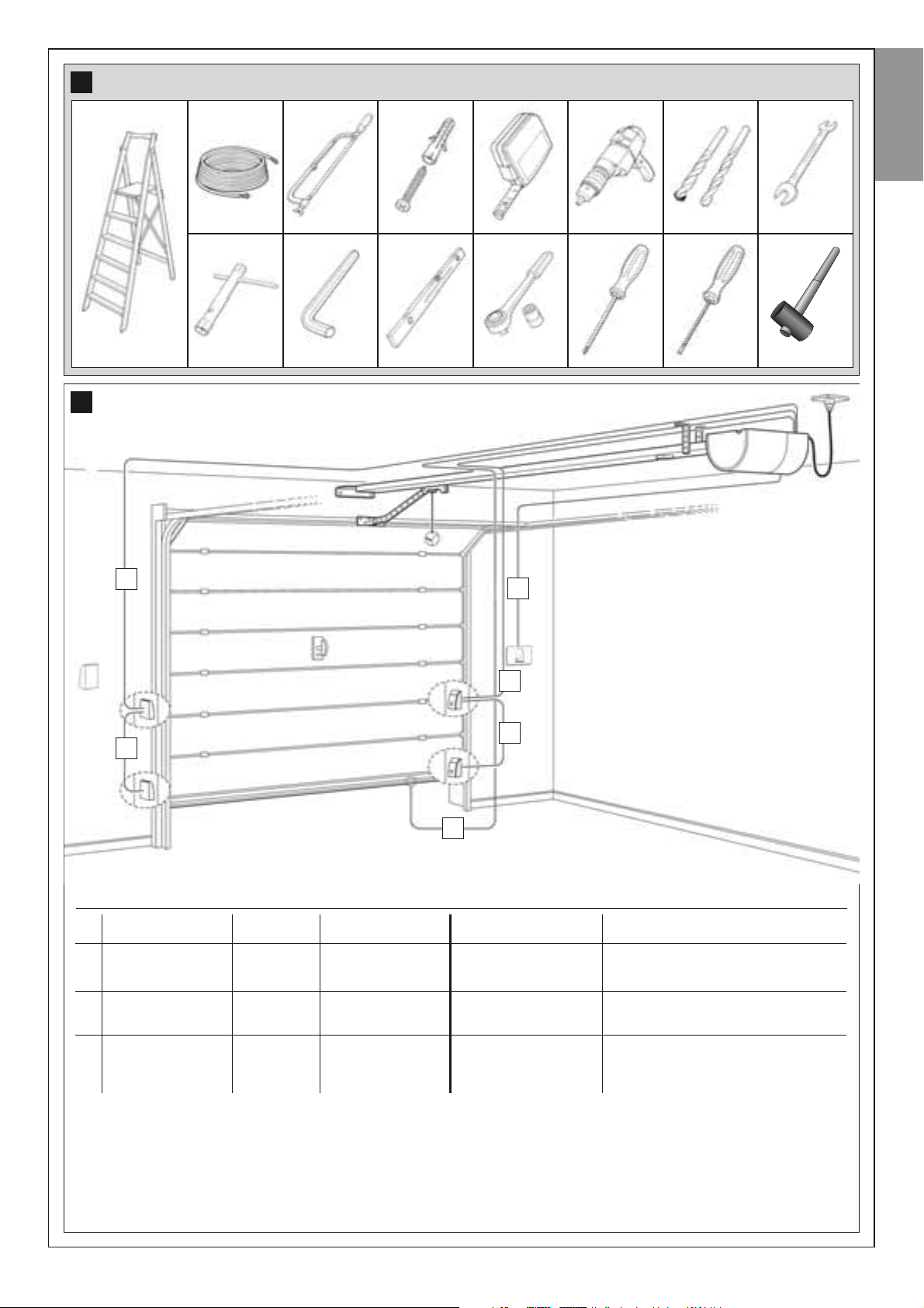
4.1.4 – Checking the tools required for the work
Before starting installation, ensure that there is all equipment and materials required for the work concerned (see example in fig. 9); also ensure
that all items are in good condition and comply with local safety standards.
4.1.5 – Preliminary set-up work
Dig the routes for the ducting used for electrical cables, or alternatively
external ducting can be laid, after which the pipelines can be embedded
in concrete and other preparation work for the installation can be completed to finalise the site ready for subsequent installation operations.
CAUTION! – Position the ends of the ducting used for electrical
cables in the vicinity of the points envisaged for fixture of the various
components.
Notes:
• The ducting serves to protect electrical cables and prevent accidental
damage in the event of impact.
• The “fixed” control devices must be visible from the door but positioned
far from moving parts and at a minimum height of 150 mm.
locate the approximate position for
D
M
G
4.2 – LAYING THE ELECTRIC CABLES
With the exception of the system connection to the mains by means of
the plug and socket, the rest of the system runs on very low voltage
(approx. 24 V) and therefore laying of electric cables may be performed by
personnel with standard skills, provided that all instructions in this manual
are strictly observed.
For laying electric cables, refer to fig. 10 specifying the type of cable to be
used for each connection.
WARNINGS:
– While laying the electrical cables, do NOT make any electrical con
nections.
– Arrange for a qualified electrician to install a Shuko 16 A socket,
suitably protected, for insertion of the gearmotor power plug. The
socket must be positioned so that after connection of the power
cable plug, the cable does not hang in the vicinity of mobile parts or
hazardous areas.
English – 7
-
6
English
c
b
a
h
e
d
f
l
m
g
g
7
8
8 – English
9
10
English
A
B
A
A
A
C
Technical specifications of electric cables (note 1)
Devices
A
Safety
photocells
B
Control
pushbutton
C
Safety pushbutton
– sensitive edges –
etc.
Note 1 – The cables required for the set-up of the system (not included in the pack) may vary according to the quantity and type
of devices envisaged for the installation..
Note 2 – The connections to terminals 1-2 (Stop), 4-5 (Step-step) and 3-5 (Photo) can be made using a single cable with several
internal wires.
Terminals
3 - 5
3 - 4
1 - 2
Function
PHOTO input
Input
STEP-STEP
STOP Input
Cable type
TX Cable 2 x 0,25 mm
RX Cable 3 x 0,25 mm
Cable 2 x 0,25 mm
Cable 2 x 0,25 mm
Maximum admissible length
2
2
2
2
20 m (note 2)
20 m (note 2)
20 m (note 2)
20 m (note 2)
CAUTION!–
ronments is recommended.
The cables used must be suited to the installation environment; for example a cable type H03VV-F for indoor envi-
English – 9
INSTALLATION: COMPONENT ASSEMBLY AND CONNECTIONS
STEP 5
English
5.1 – INSTALLING THE AUTOMATION COMPONENTS
WARNINGS
• Incorrect installation may cause serious physical injury to those
working on or using the system.
• Before starting automation assembly, make the preliminary checks
as described in STEP 3.
After laying the electric cables, proceed with assembly of the mechanical
parts of the guides and gearmotor, in the sequence specified below.
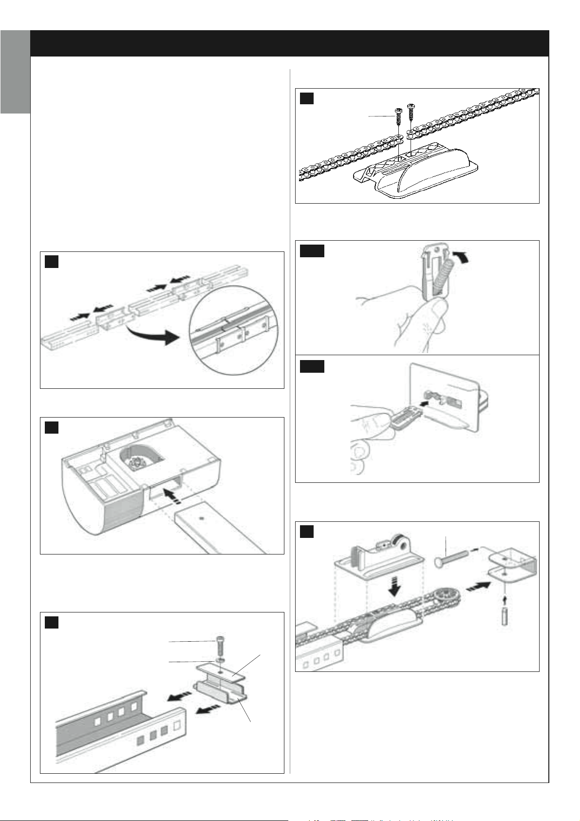
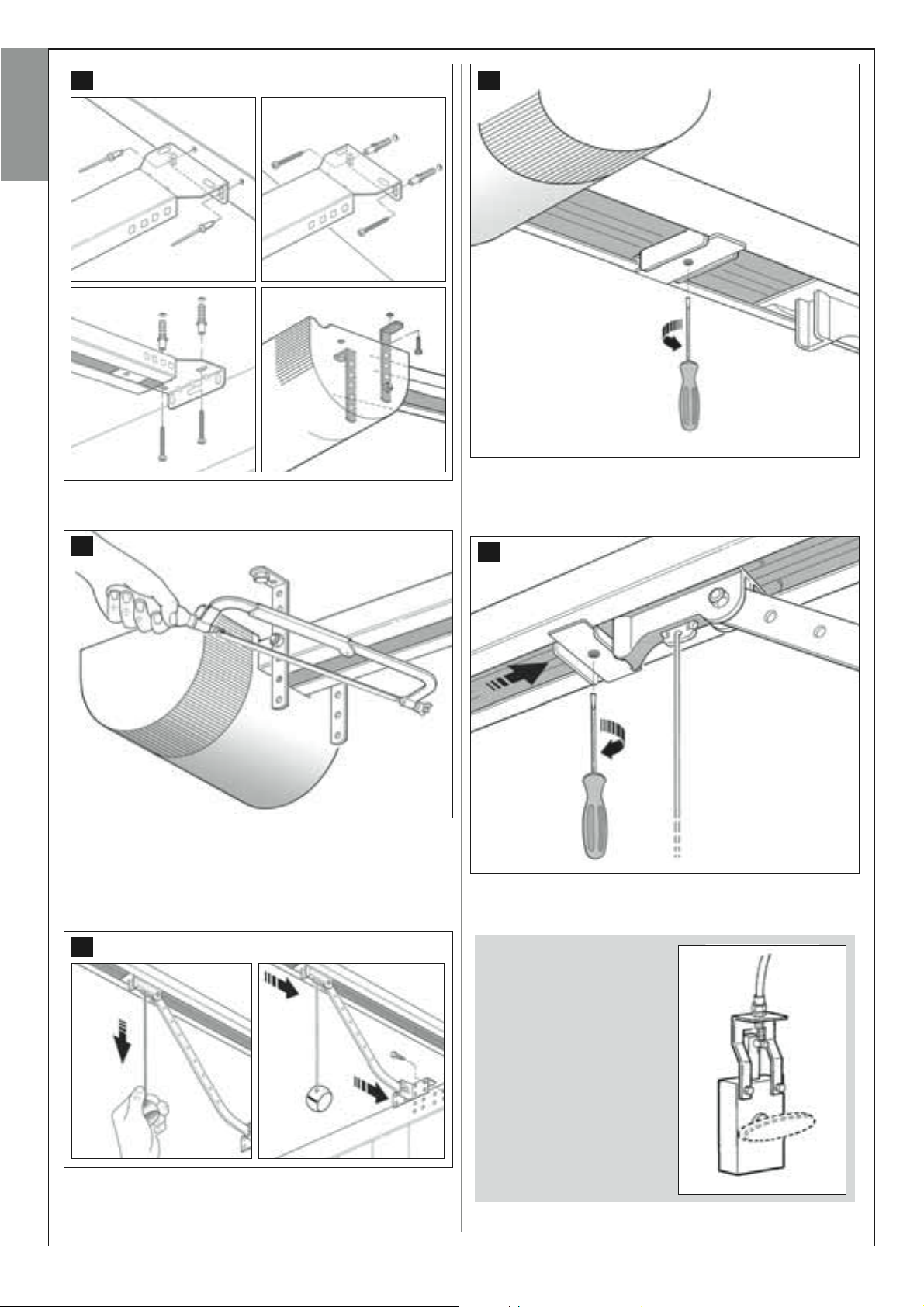
01. Only for models TS432B and TS432Be: using a mallet, securely
join the three guide sections inside the two joining brackets (fig. 11).
Important – the guides must slide inside the brackets until they click
firmly into place.
11
04. Use two screws to secure the ends of the chain into the groove on
the carriage plate (fig. 14).
14
V3,5 x 15
05. Fit the spring on the support supplied (fig. 15-a) and insert the
assembly in the carriage plate (the plate not used to secure the
chain) (fig. 15-b).
15-a
02. Insert the guide in the seat on the gearmotor (fig. 12).
12
03. Insert the travel limit mechanical stop (a) in the guide and move it
close to the gearmotor; then position plate (b) onto the stop and
secure the assembly by means of a screw (fig. 13). Note – The
screw must NOT be tightened excessively as the limit stop must
later be moved to its final position.
13
V6 x 30
b
R06 (open)
15-b
06. Join the two carriage plates; insert the screw in the support of the
drive pulley; position the drive pulley in the chain and mount the
assembly onto the drive bracket with the pin supplied (fig. 16).
16
V8 x 45
10 – English
07. Insert the chain and carriage inside the guide, taking care to observe
the following:
Fig. 17-a) position the side of the carriage with the chain fixed with
the screws on the same side as the contro unit cover;
Fig. 17-b) position the carriage to approx. mid-way on the guide.
a
08. Pass the chain around the pinion of the gearmotor and close the
assembly with the protection cover (fig. 18).
09. Insert the bracket on the end of the guide and secure the two ele-
ments by means of a nut and washer (fig. 19).
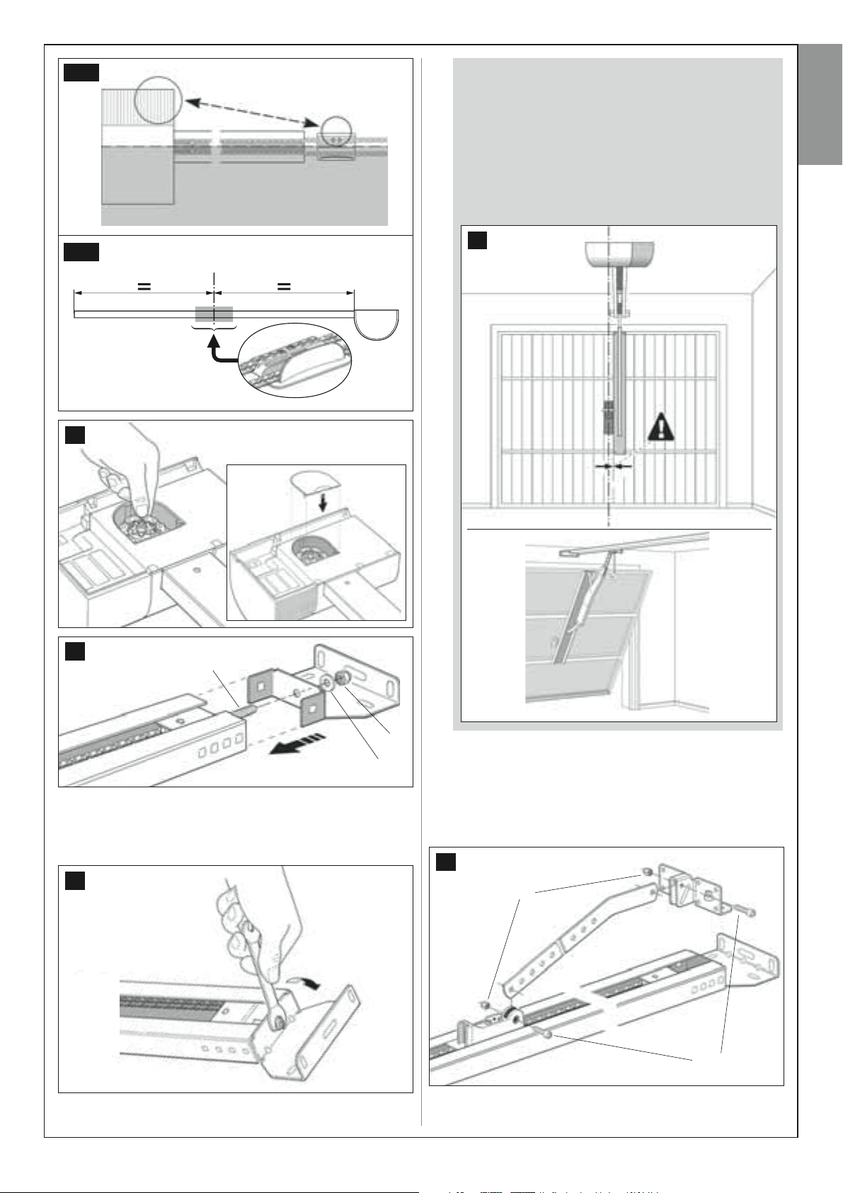
17-a
11.
If the door to be automated is “up-and-over” (projecting or nonprojecting - fig. 1), the oscillating arm mod. MA must be fitted
(fig. 21). Then proceed with assembly of the various arm compo-
nents. IMPORTANT – Take care to move the arm as close as
possible to the handle of the door.
For assembly of the drive rod, refer to point 12.
Note – for assembly of the accessory, follow the instructions supplied in the pack.
FOR UP-AND-OVER DOORS ONLY
English
17-b
18
21
19
V8 x 45
M8
R8 x 24
10. Tension the chain by tightening the nut on the screw of the drive
bracket (fig. 20). CAUTION – if the chain is tensioned excessive-
ly, this may cause excessive stress and damage the gearmotor;
if under-tensioned this may cause unpleasant noise.
20
12. CAUTION! – If the door is up-and-over, use the drive rod sup-
plied with the oscillating arm for this operation.
Before fitting the drive rod, cut this to a length that ensures observance of recommended distance E shown in fig. 3. Then use screws
and nuts to secure one end of the drive rod to the bracket (the one to
be fixed to the door or oscillating arm) and the other end to the carriage (fig. 22).
22
M6
V6 x 18
English – 11
13. Fix one end of the manual release cord to the carriage and the other
end to the knob (fig. 23). Note – Ensure that the manual release
knob is positioned at a maximum height of 180 cm from the ground.
23
English
5.2 – INSTALLING THE BUFFER
BATTERIES mod. ME
The buffer batteries are self-charging with a voltage of 12V and power of
0,8 Ah. These are particularly useful in the event of a sudden power failure.
The gearmotor enables installation of 2 batteries.
In general, when charged, the batteries guarantee an autonomy of
approx. 6 - 7 consecutive movement cycles (1 cycle = opening -closing)
This value can vary according to the type and weight of door.
IMPORTANT – The batteries must be installed before mounting
the automation on the ceiling and wall.
To install the buffer batteries, proceed as follows:
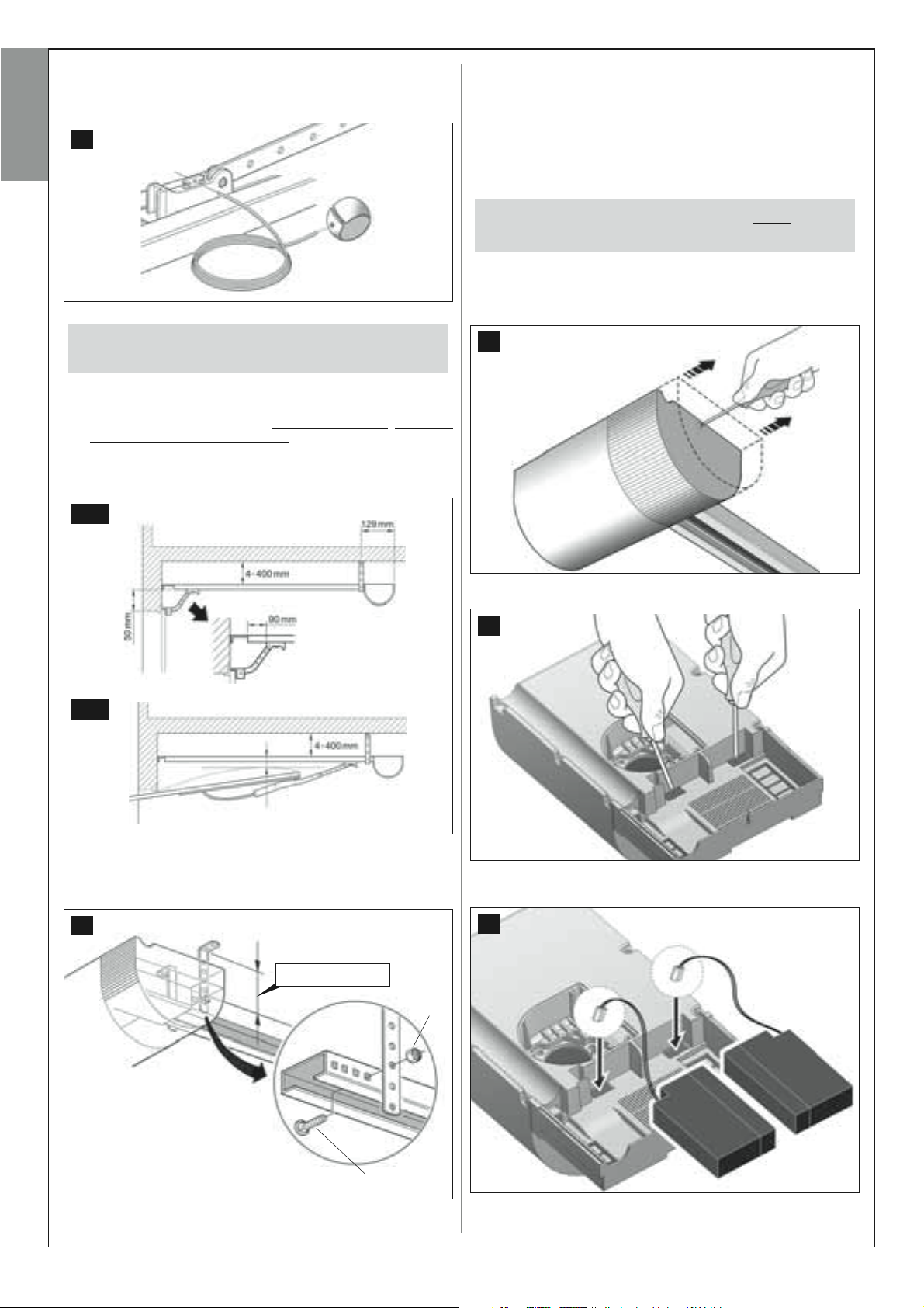
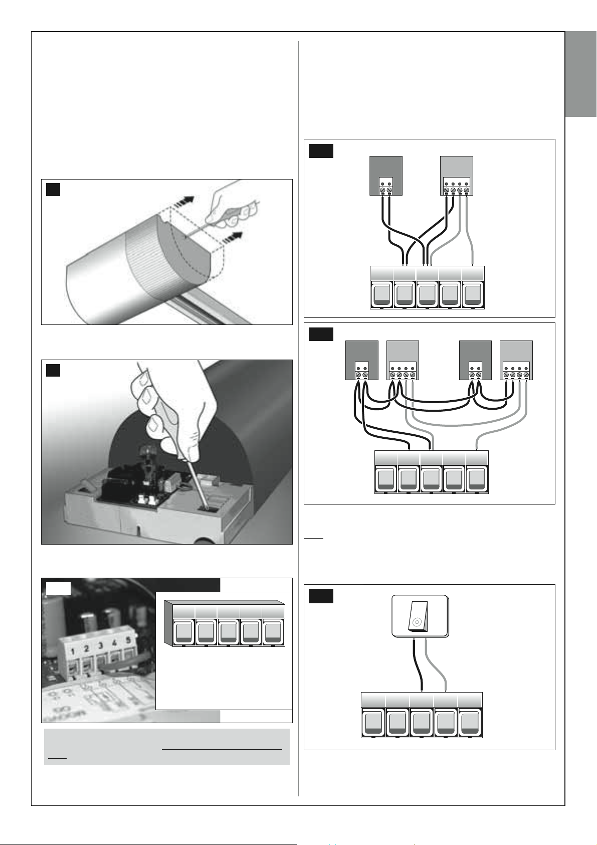
01. Remove the screw of the control unit protection cover and remove
the cover (fig. 26).
IMPORTANT! – Perform the operations below the door CLOSED.
14. • If the door is SECTIONAL: establish the length of distance B con-
sidering the constraints of values A and E (fig. 24-a).
• If the door is UP-AND-OVER: establish the length o
considering the constraints of value F (fig. 24-b).
Note – If values A, E or F allow, the automation can also be fixed
directly onto the ceiling (minimum 4 mm).
24-a
f distance B
D
B
E
A
24-b
B
26
02. Use a screwdriver to open the two cable routing slots (fig. 27).
27
from 65 to 100 mm
F
15. Fold the two ceiling mounting brackets to an “L” and mount in the
vicinity of the gearmotor, by means of screws and nuts (fig. 25).
Note – choose the most suitable hole on the brackets to observe
distance B selected in point 14.
25
(4 ÷ 400 mm)
B
M6
V6 x 14
03. Insert the battery cables in the cable routing slots (fig. 28) and posi-
tion each battery in the relative seat (fig. 29).
28
12 – English
29
CAUTION! - The point below (05 – electrical connection of
the buffer battery to the control unit ) must only be performed after completing all installation and programming
phases, as the battery is an emergency power source.
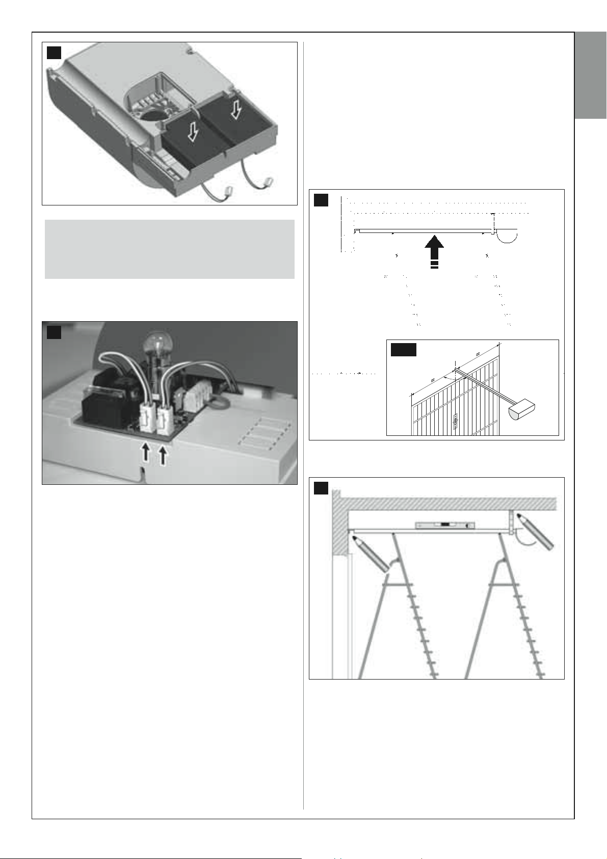
05. On the side of the control unit, insert the battery connectors in the
two sockets. CAUTION! – Do not invert polarity: the connector
grippers must face outwards (fig. 30).
30
5.3 – FIXING THE AUTOMATION TO THE WALL,
CEILING, AND DOOR
After assembly of the guide and gearmotor, fix the automation to the wall,
ceiling and door as follows.
01. Using a suitable means of support (ladder, poles or similar) lift the
gearmotor from the ground an position at the required height so that
the guide brackets are placed against the ceiling and wall above the
door (fig. 31). IMPORTANT – (fig. 31-a) align the guide and gearmo-
tor with the vertical axis of the door and perpendicular to the latter
(90° angle). Note – In the case of up-and-over doors, the guide must
be aligned with the oscillating arm.
Also ensure observance of the values A, B, E in fig. 3 and values B,
F in fig. 4.
31
English
On completion of installation, after powering up the system, the batteries
will start to self-charge and will be operative only when fully charged (usually after 12 hours).
WARNINGS
To guarantee optimal lifetime of the buffer battery, the following warnings should be
observed:
• The buffer battery is an emergency device: Therefore it should only be used moderately in the event of real necessity. Excessive and continuous use can lead to
overheating of the elements, which over time may reduce the normal lifetime of the
battery.
• Never leave the automation powered exclusively by the buffer battery for periods
longer than a day: The elements may overheat excessively and impair lifetime of
the battery.
Therefore, if absent from the installation site of the automation for prolonged periods, it is recommended to detach the buffer battery terminal connected to the
control unit.
• When the buffer battery is completely discharged, around 24 hours are required to
completely recharge.
• In the event of prolonged periods of disuse, the optional battery should be
removed and stored in a dry location to avoid the risk of leaks of harmful substances.
–––––––––––––––––––
Battery disposal
CAUTION! – Even if discharged, the batteries can contain pollutant substances and therefore must never be disposed of in common waste collection points. Dispose of according to separate waste collection methods
as envisaged by current local standards.
31-a
90°
02. Check the position of the guide, which must be perfectly horizontal,
and mark the 4 bracket fixture points, after which drill the relative
holes and insert the plugs (fig. 32).
32
03. Fix the automation to the ceiling and wall using screws and plugs
suited to the support material (fig. 33).
Notes:
• Depending on the type of wall, the bracket at the end of the guide
can be fixed by means of the rivets or screws and plugs.
• Take care when choosing the method of bracket fixture to the ceiling, taking into account the following:
– the bracket at the end of the guide must withstand the force
required to open and close the door;
– the ceiling mounted brackets must withstand the weight of the
gearmotor.
In both cases possible wear and deformation over time must be taken into account.
English – 13
33
English
04. Use a saw to cut off the excess section of the ceiling-mounted
brackets (fig. 34).
34
36
07. Move the travel limit mechanical stop up against the carriage.
Then tighten the travel limit mechanical stop screw fully down (fig. 37).
Note – During normal operation the carriage stops a few centimetres
before the mechanical stop.
37
05. (With the door closed) Pull the release knob and slide the carriage
until the anchoring bracket is positioned on the upper edge of the
sectional door, or until it reaches the connection of the oscillating arm
(up-and-over door). Then align the drive rod along the trajectory of
the guide and fix the bracket to the door using rivets or screws suited to the door material (fig. 35).
35
06. Slightly loosen the travel limit mechanical stop screw and manually
open the door until it reaches the maximum Opening position (fig. 36).
14 – English
08. To re-block the door, close it manually until it clicks firmly into place.
IMPORTANT
It is recommended to install
the external release kit
(model MU), if the door
closes an area with no other
access points. In fact, in
this situation, a simple
power failure
may prevent access to the area.
Note – for assembly of the
accessory, follow the instructions
in its pack.
STEP 6
12 12 34
TX RX
+ – + –
12345
TX RX
+ – + –
12 12 34
TX RX
+ – + –
SYSTEM DEVICE CONNECTION
After installing all devices in the system – each in the position specified in
STEP 4 – connect each device to the control unit as follows.
CAUTION! – Incorrect connections can cause faults or hazards;
therefore ensure that the specified connections are strictly observed.
For correct connections, proceed as follows:
• To connect a pair of photocells with safety function
One or more pairs of photocells with a safety function must be installed on
the system. If several pairs of photocells are installed, these must be connected in series, and the chain must be connected to terminals 3 and 5
on the control unit. The connect the power supply to terminals 2 and 3
(see example in fig. 40-a and fig. 40-b).
During the Closing manoeuvre, activation of these photocells causes
shutdown of the manoeuvre and immediate inversion of movement.
English
01. Use a screwdriver to loosen the screw on the control unit cover and
extract the cover (fig. 38), to access the terminals for electrical con-
nections of the control unit.
38
02. Use the same screwdriver to open the slots required for routing the
electric cables (fig. 39) from the various devices in the system.
39
40-a
40-b
12 12 34
03. Then connect the electric wires of the system devices to the control
unit using the terminal board with five terminals (fig. 39-a).
39-a
CAUTION – The section of electric cable connecting terminals 3
and 5 must only be removed if photocell installation is envisaged.
12345
0 VOLT (–)
Input STOP
LINE 24 Vcc (+)
Input STEP BY STEP
1
2345
• To connect a NO type pushbutton used for manoeuvre control
An “NO” type pushbutton can be installed on the system, i.e. “normally
” to control manoeuvres in “step-step” mode (for details on this
open
mode, see STEP 9). Connect this pushbutton to terminals 3 and 4 on the
control unit.
Note – If several pushbuttons are installed to control manoeuvres, connect these in parallel as shown in the example in fig. 40-c and fig. 40-d.
40-c
Input PHOTO
12345
English – 15
12345
40-d
12345
12345
12345
12345
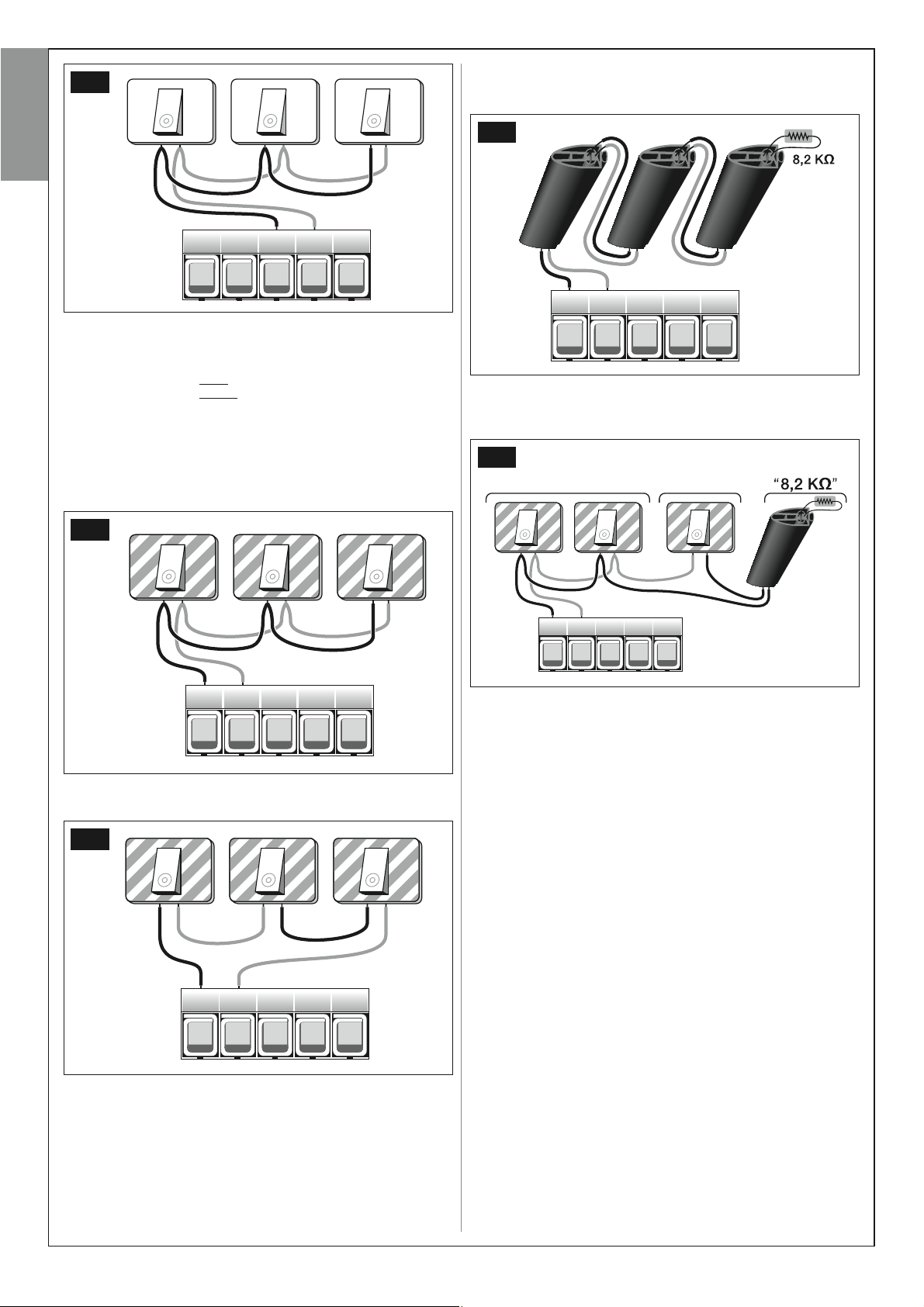
C) – to connect a series of devices with constant resistance 8,2 K1, use
a “parallel” connection layout, positioning the resistance (8,2K1) on the
last device, as shown in the example in fig. 40-g.
English
• To connect safety devices other than photocells
As well as photocells, the system can also be equipped with other safety
devices with different types of contact. These are:
– devices with “normally open
– devices with “normally closed” contact (“NC”);
– devices with constant resistance 8,2 K1.
These devices can be connected to terminals 1 and 2 on the control unit;
also more than one device can be connected to the same terminals as
described below:
A) – to connect a series of “NO” type devices, use a “parallel” connection
layout as shown the example in fig. 40-e.
40-e
” contact (“NO”);
40-g
D) – to connect a series of devices with different contact types (“NO”,
“NC” and constant resistance 8,2 K1), use a connection layout in series
and in parallel as shown in the example in fig. 40-h.
40-h
“NA”“NC”
B) – to connect a series of “NC” devices, use a connection layout “in
series” as shown in the example in fig. 40-f.
40-f
Note – Only the safety devices with an output with constant resistance 8,2 K
the standard EN 954-1.
Activation of these safety devices stops the manoeuvre in progress and a
brief inversion of movement.
• Powering devices other than those specified in this chapter
As well as those mentioned, the system can also be equipped with other
safety devices such as a universal relay receiver. These devices must be
connected to terminals 2 and 3 on the control unit.
CAUTION! – There is a 24 Vdc power voltage on terminals 2 and 3
with delivery of a current of 100 mA. The total absorbed current of
the various devices connected to these terminals must not exceed
this value.
WARNING – On completion of connections, secure all cables using special clamps and refit the cover on the control unit.
1
guarantee safety category 3 against faults according to
16 – English
POWER SUPPLY CONNECTION
STEP 7
WARNINGS!
– The PVC power cable supplied is suitable for indoor installa-
tions.
The final connection
must be performed by a qualified electrician, in compliance
with local standards and the instructions in the section “Tasks
reserved for qualified technicians”.
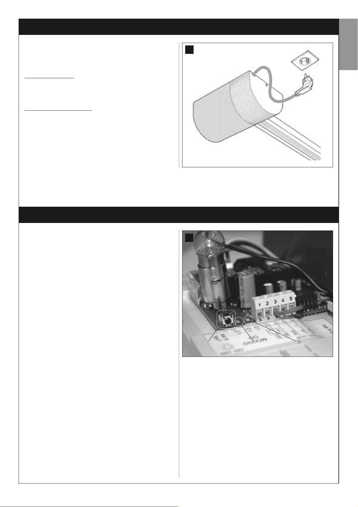
To perform the automation operation and programming tests, insert the
power plug of the control unit (supplied) in a mains socket (fig. 41). If
the socket is far from the automation, use a suitable extension lead.
of the automation to the electrical mains,
INITIAL START-UP AND ELECTRICAL CONNECTION CHECK
41
English
STEP 8
CAUTION! The following operations described in this manual will be
performed on live electrical circuits and therefore manoeuvres may
be hazardous! Therefore proceed with care.
After powering up the control unit (fig. 41) perform the following opera-
tions, checking conformity of results:
• Immediately after start-up, the red led (fig. 42) flashes quickly for a few
seconds, after which the red and green leds light up alternately; then the
green led turns off and the red led continues flashing at regular intervals
every second (= control unit operating status OK).
CAUTION! - If the red led does not flash as described above, disconnect the Control unit from the power supply and carefully check
all connections (refer also to the paragraph “What to do if....”).
• If the system is equipped with photocells, check the RX element to
ensure that the led is OFF (= operation OK) or ON (= obstacle present). If
the Led is flashing, this means that the signal is poor and subject to incorrect photocell alignment.
• If the system is equipped with a radio control keypad, check operation
with reference to the relative instruction manual.
42
Key “P1” Green Led Red Led
English – 17
PROGRAMMING THE AUTOMATION
STEP 9
English
WARNINGS for programming:
• Always read the procedure first and then perform the operations in the
correct sequence. without leaving more than 10 seconds between releasing one key and pressing the next.
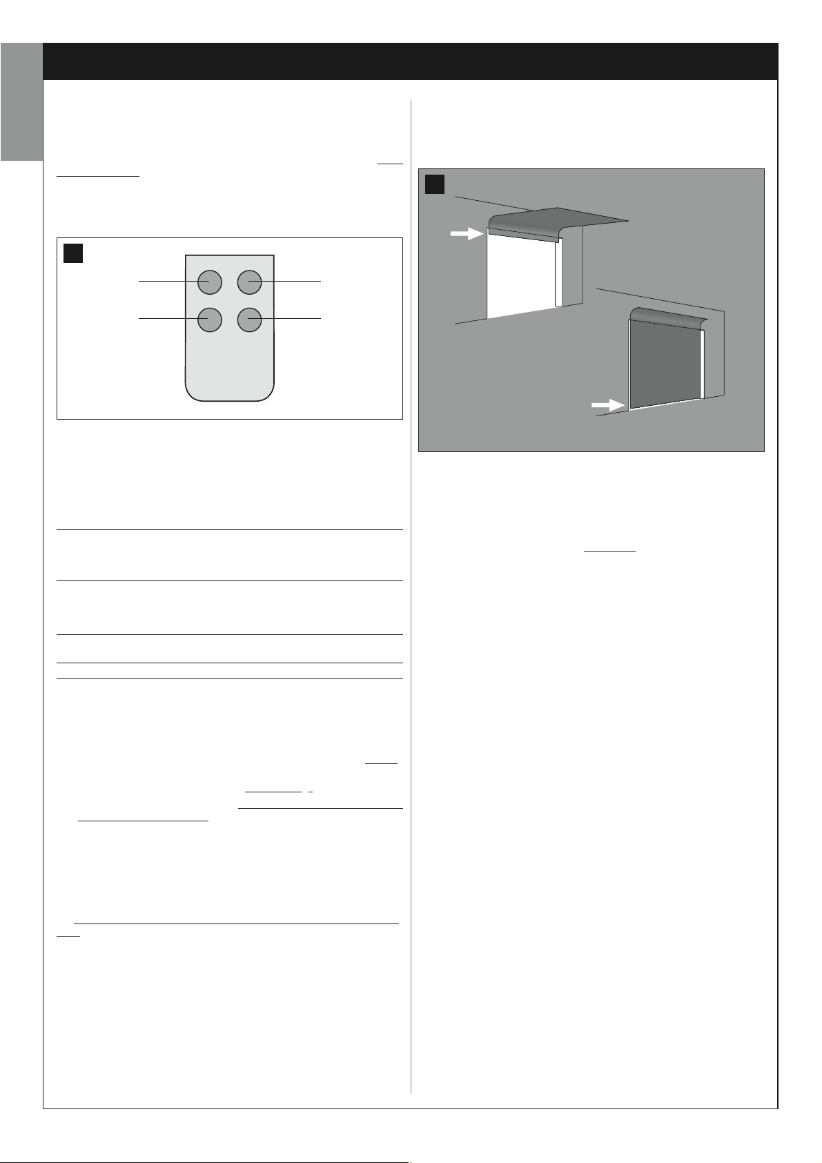
• In this manual the transmitter keys are identified by means of numbers.
To check the correspondence of numbers and the transmitter keys see
fig. 43.
43
T1
T3
9.1 – MEMORISATION OF TRANSMITTER MOD. MT4
To enable control of the automation with the transmitter, the keys must be
memorised in the control unit memory.
Memorisation enables the association of each key with the required command, selecting from the following:
1 = Step-Step: Corresponds to the sequence ... Open - Stop – Close -
Stop ... The first command activates Opening; the next, with the leaf mov-
ing, activates Stop; the third activates Closure; the fourth with the door
moving activates Stop and so on…
2 = Step-Open: Corresponds to the sequence ... Open - Stop – Close
- Open ... The first command activates Opening; the next, with the leaf
moving, activates Stop; the third activates Closure; the fourth with the
door moving activates Open and so on...
3 = Partial open: corresponds to a brief opening of the door. This command is only enabled if the door is completely closed.
4 = Courtesy light: ... On - Off - On ...
A single procedure memorises a single key of the transmitter; this can be
memorised both on the present control unit and on control units of other
automations. The control unit memory can memorise up to 150 keys.
For each key to be memorised, repeat the following procedure.
01. Select which transmitter key is to be memorised (for example: Key T3).
02. Decide on the command (from those listed below) to be associated
with the selected key (for example: Command “2”).
03. Press “P1” (on the Control unit) the same number of times as the
selected command number (in the example “2”, i.e. twice) and check
that the green led emits the same number of quick flashes (repeated
at regular intervals).
04. (within 10 seconds) Press and hold the transmitter key to be memo-
rised for at least 2 seconds (in the example, key T3).
If the memorisation procedure is successful, the green led emits 3 long
flashes (= memorisation OK). Note – Before the 10 second interval elaps-
es, the key of a NEW transmitter with the same command can be memorised (useful, for example, when several transmitters need to be memorised on the same control unit).
Otherwise wait until the green led turns off (= procedure completed) and
for the red led to resume flashing at regular intervals.
T2
T4
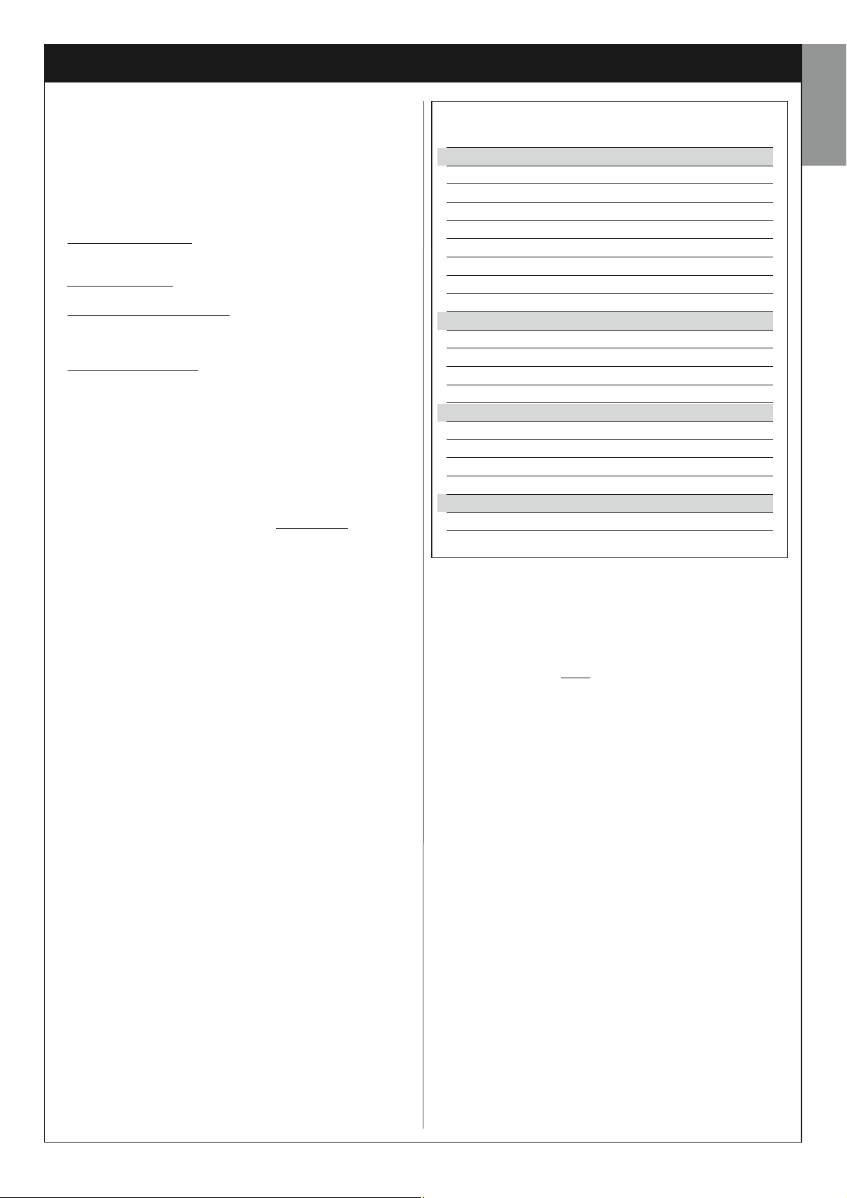
9.2 – MEMORISING THE DOOR “OPENING” AND
“CLOSING” TRAVEL LIMIT POSITIONS
The “Closing” limit position corresponds to the maximum door closing
position and the “Opening” limit to maximum opening (fig. 44).
44
“Opening” travel limit position
“Closing” travel limit position
In this installation phase, the control unit must memorise the maximum
door “Closing” and “Opening” positions and the configuration of the
STOP input, using the following procedure:
CAUTION! – The following operations must be performed using
exclusively key P1 on the gearmotor control unit.
01. Ensure that the drive carriage is engaged
02. Press and hold “P1” on the Control unit (for approx. 5 seconds) until
the red light illuminates, then release.
03. At this point the control unit independently starts 3 consecutive
manoeuvres (Closing – Opening – Closing) to automatically memorise the two travel limit positions. Note – During the 3 manoeuvres,
the courtesy light flashes.
Caution!– During the 3 manoeuvres, if a safety devices is activated or P1 is pressed, the control unit interrupts and automatically cancels the entire procedure. In this case the entire procedure needs to be repeated.
04. Lastly, use the transmitter key T1 activate 3 or 4 complete Opening
and Closing manoeuvres (these manoeuvres are required for the
control unit to memorise the force values required to move the door
at all points of travel).
Caution! – These manoeuvres must not be interrupted; should
this occur, the entire procedure must be repeated.
CAUTION! – During the position search process, if the chain on the
pinion pulley of the motor emits a rhythmic noise, indicating that tensioning is insufficient. In this case, interrupt the procedure by pressing “P1” on the control unit: then tension the chain by tightening nut
D (fig. 4) and repeat the procedure from the beginning.
This procedure can be repeated at any time: for example after a mechanical travel stop has been moved on the guide.
.
18 – English
ADJUSTMENTS AND OTHER OPTIONAL FUNCTIONS
The control unit has a number of optional functions to enable the user to
add specific functionalities to the automation, thus personalising the product according to special needs.
10 – AUTOMATION OPERATION ADJUSTMENT
To personalise operation of the automation, a number of functions can be
enabled or disabled, also with the option for modifications to settings as
required. The functions are:
• AUTOMATIC CLOSURE
the Opening manoeuvre command by the user, the control unit automatically closes the door again after a set time interval.
• MOVEMENT SPEED
of the automation implemented to move the door.
• SENSITIVITY TO OBSTACLES
accidentally stops door movement (a gust of wind, a vehicle, person etc.)
this function promptly detects the increase in motor stress to contract the
obstacle and activates immediate and brief inversion of movement.
• PRESSURE DISCHARGE
the door has closed completely, the motor continues to “push” the door
for a brief interval, to ensure perfect closure. Immediately afterwards, this
function activates a very brief inversion of movement, to reduce excessive
pressure exerted by the motor on the door.
The values of these functions can be set according to personal requirements using the following procedure with a transmitter that has at least
one key already memorised on the control unit.
Note – During this procedure, each time a key is pressed the courtesy
light illuminates briefly.
01. Press and hold the keys “T1” and “T2” simultaneously on the trans-
mitter for at least 5 seconds, after which release.
The two leds (green and red) on the Control unit flash to indicate entry
to function programming mode (the leds continue to flash throughout
the procedure).
02. Press and hold a transmitter key (already memorised on that of the
control unit) for at least 1 second (the green Led emits one flash).
03. Then select one of the four functions available and on the transmitter
press the key associated with the function for at least 1 second (the
green Led emits one flash):
• Automatic closure = (press key “T1”)
• Movement speed = (press key “T2”)
• Sensitivity to obstacles = (press key “T3”)
• Pressure discharge (= press key “T4”)
04. Lastly, refer to Table 4, select the required value in correspondence
with the selected function and on the transmitter press the key associated with the selected value for at least 1 second (the green and
red Leds emit one confirmation flash).
. When this function is enabled, at the end of
. This function enables entry of the required speed
. During a manoeuvre, if an obstacle
. At the end of the Closing manoeuvre, after
TABLE 4
AUTOMATIC CLOSURE
No closure —> (press key “T1”)
Closure after 15 seconds —> (press key “T2”)
Closure after 30 seconds —> (press key “T3”)
Closure after 60 seconds —> (press key “T4”)
MOVEMENT SPEED
Low Opening / Low closing —> (press key “T1”)
Low Opening / Fast closing —> (press key “T2”)
Fast Opening / Low closing —> (press key “T3”)
Fast Opening / Fast closing —> (press key “T4”)
SENSITIVITY TO OBSTACLES
High —> (press key “T1”)
Medium high —> (press key “T2”)
Medium low —> (press key “T3”)
Low —> (press key “T4”)
PRESSURE DISCHARGE
No discharge —> (press key “T1”)
Minimum —> (press key “T2”)
Medium —> (press key “T3”)
Maximum —> (press key “T4”)
Notes to Table 4:
– The Table states the values available for each of the 4 special functions
and the corresponding key to be pressed on the transmitter for selection
of the specific value.
– The factory settings are highlighted in grey.
11 – MEMORISING A NEW TRANSMITTER WITH
PROCEDURE IN THE VICINITY OF THE CONTROL UNIT
[with a transmitter already memorised]
A NEW transmitter can be memorised in the control unit memory without
acting directly on key P1 of the control unit, but by simply working within
its reception range. To use this procedure, an OLD transmitter, previously
memorised and operative, is required. The procedure enables the NEW
transmitter to receive the settings of the OLD version.
English
Warning – The procedure must be performed within the reception
range of the receiver (maximum 10-20 m from receiver).
01. On the NEW transmitter, press and hold the key to be memorised for
at least 5 seconds and then release.
02. On the OLD transmitter, slowly press the control key to be memo-
rised on the other transmitter 3 times.
03. On the NEW transmitter, press the same key pressed in point 01 once.
Note – Repeat the same procedure for each key to be memorised.
12 – DELETING DATA FROM THE CONTROL UNIT MEMORY
Data in the control unit memory can be deleted partially or totally as
required. To do this, the following procedures can be used, as required:
• Deletion of a command on a transmitter already memorised
• Deletion of other data memorised on the control unit
on a transmitter already memorised
The following procedure enables deletion of a single command assigned
to a transmitter key from the control unit memory.
Deleting a command
English – 19
Note – During the procedure, the red and green leds remain permanently lit.
01. Press and hold the key “P1” on the Control unit for at least 10 sec-
onds: the green Led illuminates first, then the red led illuminates after
5 seconds and then both, to indicate that the Control unit has entered
English
memory deletion mode (WARNING! do not release the key P1!).
02. Without releasing key
the control unit recognises this operation, the green led emits a short
flash, after which the P1 key and transmitter key can be released.
P1 press the transmitter key to be deleted: if
data memorised on the control unit
The following procedure enables deletion of various types of memorised
data from the control unit memory, as specified in Table 5.
Note – During the procedure, the red and green leds remain permanently lit.
01. Press and hold the key “P1” on the Control unit for at least 10 sec-
onds: the green Led illuminates first, then the red led illuminates after
5 seconds and then both, to indicate that the Control unit has
entered memory deletion mode. Then release the key.
02. With reference to Table 5, select the data to be deleted and press P1
the same number of times as the number of presses specified in
brackets (the green led emits one flash each time the P1 key is
pressed).
03. 5 seconds after the key “P1” is pressed for the last time, if
successful, both leds (red and green) flash quickly (= memory deleted!).
Note – Before deletion, there is a margin time of 5 seconds, in which
the user has the option to change decision and exit the procedure
without deleting data by pressing key P1 five times.
IMPORTANT! - After deletion of the “Memory of
it positions” and “TOTAL Memory”, the procedure 9.2 – “Learning the
Closing and Opening limit positions” must be repeated.
Deleting other
deletion is
Closing and Opening lim-
TABLE 5
• Memory of Optional Function values (= 1 press)
• Memory of “Closing ” and “Opening” limit positions (= 2 presses)
• Memory of Transmitters (= 3 presses)
• TOTAL memory (= 4 presses) Note – deletes the first three mem-
ories in one process
20 – English

WHAT TO DO IF... (troubleshooting guide)
During normal operation, the control unit constantly monitors the automation processes and is designed to indicate any faults that arise, by means of a
pre-set sequence of flashes emitted by the courtesy light and red led “L1” on the control unit (the diagnostics flashes always refer to the last action performed by the automation). For an explanation of the number of flashes and associated cause, refer to Table 6 below:
TABLE 6
English
Flashes
2 flashes - pause - 2 flashes
3 flashes - pause - 3 flashes
4 flashes - pause - 4 flashes
5 flashes - pause - 5 flashes
6 flashes - pause - 6 flashes
Problem
During the Closing manoeuvre, the door stops and
inverts the current movement.
During the Opening or Closing manoeuvre the door
blocks suddenly and the control unit activates a brief
inversion of the manoeuvre in progress
During the Opening or Closing manoeuvre the door
blocks suddenly and the control unit activates a
Stop followed by a brief inversion of movement.
The automation does not respond to commands.
After a series of manoeuvres sent consecutively, the
automation is blocked.
Solution
This reaction is caused by the activation of a
specific pair of photocells in the system, on
detection of an obstacle. Therefore remove the
obstacle on the trajectory of these photocells.
The leafs are subject to increased friction due to
a sudden obstruction (gust of wind, vehicle, person etc.). If adjustment to sensitivity is required,
refer to the Chapter “Adjustments and other
optional Functions”.
A safety device installed (other than photocells,
such as sensitive edges) has detected a sudden
obstacle.
Therefore remove the obstacle.
There is a system configuration error. Delete the
entire memory of the control unit and repeat
installation.
The maximum admissible number of consecutive manoeuvres has been exceeded, causing
excessive overheating. Wait for a few minutes to
enable the temperature to return below the maximum limit.
7 flashes - pause - 7 flashes
The automation does not respond to commands.
Error in internal electric circuits. Disconnect all
power circuits, wait a few seconds and then reconnect. Retry a command; if the automation
does not respond this may indicate a serious
fault with the electrical board of the control unit
or motor wiring. Check and make replacements
as necessary.
English – 21
Tasks reserved for qualified technicians
CAUTION! – All operations in this section must be performed exclusively by skilled and qualified
English
CAUTION!– When making this connection, the electrical mains power line must be equipped with short-circuit protection device (between the automation and the mains).
The electrical mains line must also be equipped with a power disconnect device (with overvoltage category III, i.e. minimum gap between contacts of 3
mm) or an equivalent system such as socket with removable plug.
This device, when necessary, guarantees fast and safe disconnection of the power supply and therefore must be placed in a location visible from the
automation. If the power disconnect device is not in the vicinity of the automation and not visible from the latter, it must be fitted with a lockout facility
to prevent inadvertent or unauthorised connection.
Note – The disconnect devices are not supplied with the product.
These are the most important phases of automation set-up to ensure maximum system safety. The testing procedure described can also be performed
as a periodic check of automation devices.
Testing and commissioning of the automation must be performed by skilled and qualified personnel, who are responsible for the tests required to verify the solutions adopted according to the risks present, and for ensuring observance of all legal provisions, standards and regulations, and in particular
all requirements of the standard EN 12445, which establishes the test methods for checking automations for garage doors.
personnel, in observance of the instructions in the manual, and current local legislation and safety standards in the place of installation.
CONNECTING THE AUTOMATION TO THE ELECTRICAL MAINS
AUTOMATION TESTING AND COMMISSIONING
AUTOMATION TESTING
1 Ensure that all specifications in STEP 1 regarding safety have been
strictly observed.
2 Using the transmitter, perform door opening and closing tests and
ensure that the movement corresponds to specifications.
Test several times to assess smooth operation of the door and check
for any defects in assembly or adjustment and any possible points of
friction.
3 Check operation of all system safety devices one at a time (photocells,
sensitive edges, etc.), Photocells
ing or Closing manoeuvre and check that the control unit stops the
manoeuvre and activates a total inversion of the movement (the courtesy light emits 2 flashes, twice). Sensitive edges: Activate the device
during an Opening or Closing manoeuvre and check that the control
unit stops the manoeuvre and activates a short inversion of the movement (the courtesy light emits 4 flashes, twice).
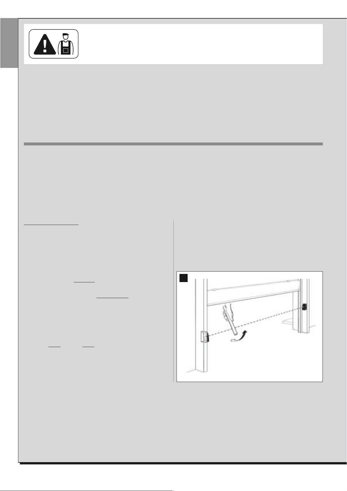
4 To check the photocells, and to ensure there is no interference with oth-
er devices, pass a cylinder (diameter 5 cm, length 30 cm) through the
optic axis joining the pair of photocells (fig. 45): pass the cylinder first
close to the TX photocell, then close to the RX and lastly at the centre
between the two. Ensure that in all cases the device engages, changing
from the active
envisaged action is generated in the control unit (for example movement inversion in the Closing manoeuvre).
status to alarm status and vice versa, and that the
: Activate the device during an Open-
5 Measure the force as specified in the standard EN 12445. If the motor
force control is used as an auxiliary function for reduction of impact
force, test and identify the setting that obtains the best results.
6 Activate a closing manoeuvre and check impact force of the door
against the mechanical stop. If necessary, test by discharging pressure
to obtain the best results.
45
22 – English
AUTOMATION COMMISSIONING
Commissioning can only be performed after positive results of all test
phases. Partial or “makeshift” commissioning is strictly prohibited.
1 Prepare the automation technical documentation, which must contain
the following documents: Overall layout drawing (see example in fig. 6,
7, 8), electrical wiring diagram (see example in STEP 6), risk assessment and relative solutions adopted (see forms to be compiled on the
website www.moovo.com), manufacturer’s declaration of conformity
for all devices used and the declaration of conformity compiled by the
installer (see section TECHNICAL DOCUMENTATION).
2 Affix a dataplate on the door, specifying at least the following data: type
of automation, name and address of manufacturer (responsible for
commissioning), serial number, year of construction and CE mark.
3 Prepare and provide the owner with the declaration of conformity; the
“CE Declaration of conformity” in the section TECHNICAL DOCUMENTATION must be compiled for this purpose.
4 Prepare and provide the owner with the form “Operation manual” in
the section TECHNICAL DOCUMENTATION .
5 Prepare and provide the owner with the form “Maintenance schedule”
in the section TECHNICAL DOCUMENTATION, containing all maintenance instructions for all devices in the automation .
6 Before commissioning the automation, ensure that the owner is ade-
quately informed of all associated risks and hazards.
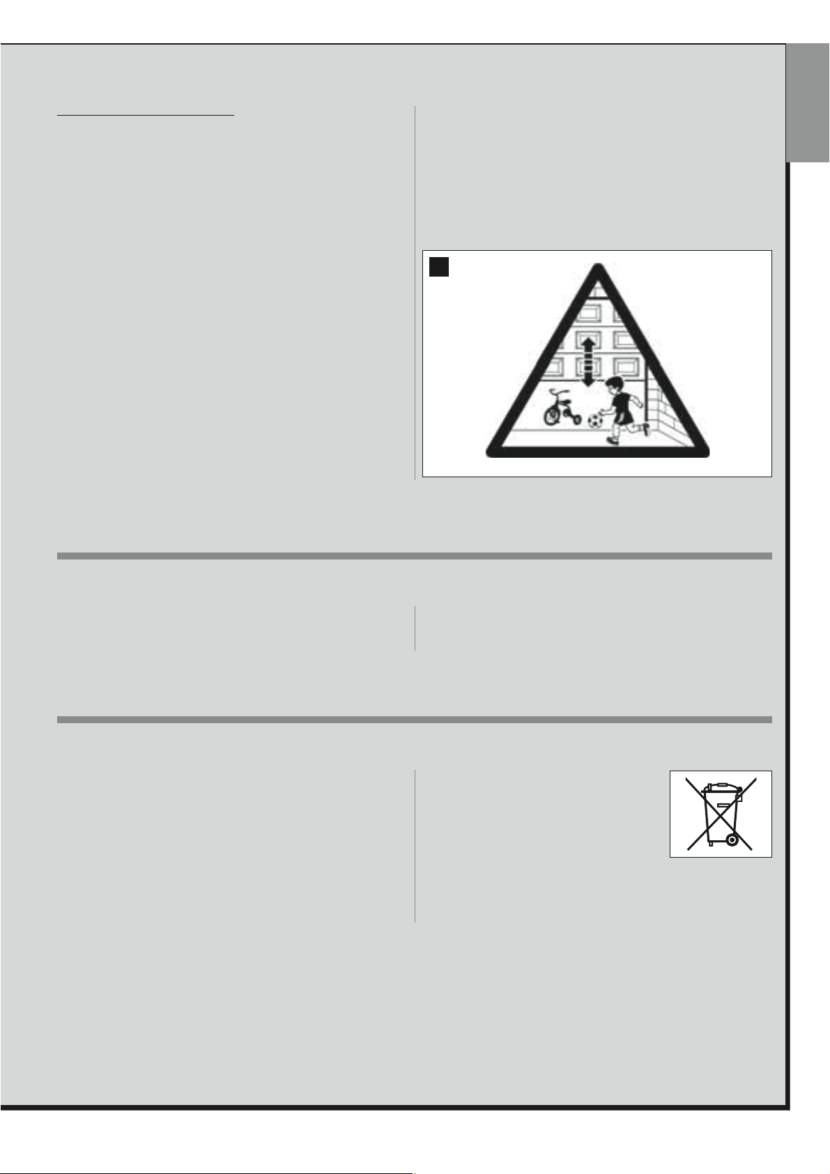
7 Permanently affix a label or plate on the door with the image shown in
fig. 46 (minimum height 60 mm) bearing the text “CAUTION: RISK OF
CRUSHING”.
46
English
PERIODIC MAINTENANCE OPERATIONS
In general, this product does not require special maintenance; however,
regular checks over time will ensure system efficiency and correct operation of the safety systems installed.
PRODUCT DISPOSAL
This product is an integral part of the automation and therefore must
be disposed together with the latter.
As in installation, also at the end of product lifetime, the disassembly and
scrapping operations must be performed by qualified personnel.
This product comprises various types of materials: some may be recycled
others must be disposed of. Seek information on the recycling and disposal systems envisaged by the local regulations in your area for this
product category.
CAUTION! – some parts of the product may contain pollutant or hazardous substances which, if disposed of into the environment, may cause
serious damage to the environment or physical health.
Therefore to ensure correct maintenance, refer to the chapter “Mainte-
nance Schedule” in the section “TECHNICAL DOCUMENTATION” at the
end of the manual.
As indicated by the symbol alongside, disposal of
this product in domestic waste is strictly prohibited. Separate the waste into categories for disposal, according to the methods envisaged by current
legislation in your area, or return the product to the
retailer when purchasing a new version.
CAUTION! – Local legislation may envisage serious fines in the event of
abusive disposal of this product.
English – 23
TECHNICAL SPECIFICATIONS OF PRODUCT COMPONENTS
WARNINGS:
– The product TS4... is produced by Nice S.p.a. (TV) I. Moovo is a commercial trademark owned by Nice S.p.a.
– All technical specifications stated in this section refer to an ambient temperature of 20°C (± 5°C).
– Nice S.p.a. reserves the right to apply modifications to the product at any time when deemed necessary, while maintaining the same functionalities and intended use.
English
GEARMOTORS TS432 - TS432e
DESCRIPTION DATA
Technology adopted 24 V motor
Power supply 230 Vac 50/60 Hz
Maximum start-up torque 12 Nm
Nominal torque 6.3 Nm
Nominal thrust 500 N
Maximum power 200 W
Movement speed 0.07 ÷ 0.13 m/s
Maximum continuous operation time 4 minutes
Maximum cycle frequency 30 per day (10 in 1 hour)
Ambient operating temperature -20° C ÷ +50° C
Dimensions 305 x 109 h x 130 (mm)
Weight 4 kg
Insulation class 1
Emergency power supply 2 batteries, 12V / 0.8Ah (only for TS432Be - TS432BeH)
Courtesy light 12 V / 10 W fitting BA15
STOP Input
STEP-STEP Input For normally open contacts
PHOTO input For safety devices with normally closed contacts
Radio receiver Built-in
Programmable functions
Functions in self-learning mode
Use in particularly acid or saline
potentially explosive atmospheres
Protection class IP 40 use indoors or in protected environments
Estimated durability (*) From 40.000 to 80.000 manoeuvre cycles
For normally open, normally closed or constant resistance 8,2 K1 contacts;
in self-learning (a variation with respect to the memorised status causes the command “STOP”).
4 programmable functions (see paragraph 6.3) Self learning of type of STOP device (NO contact,
NC contact or 8,2 K1 resistance)
Self-learning of door opening and closing positions and calculation of deceleration and
partial open points.
No
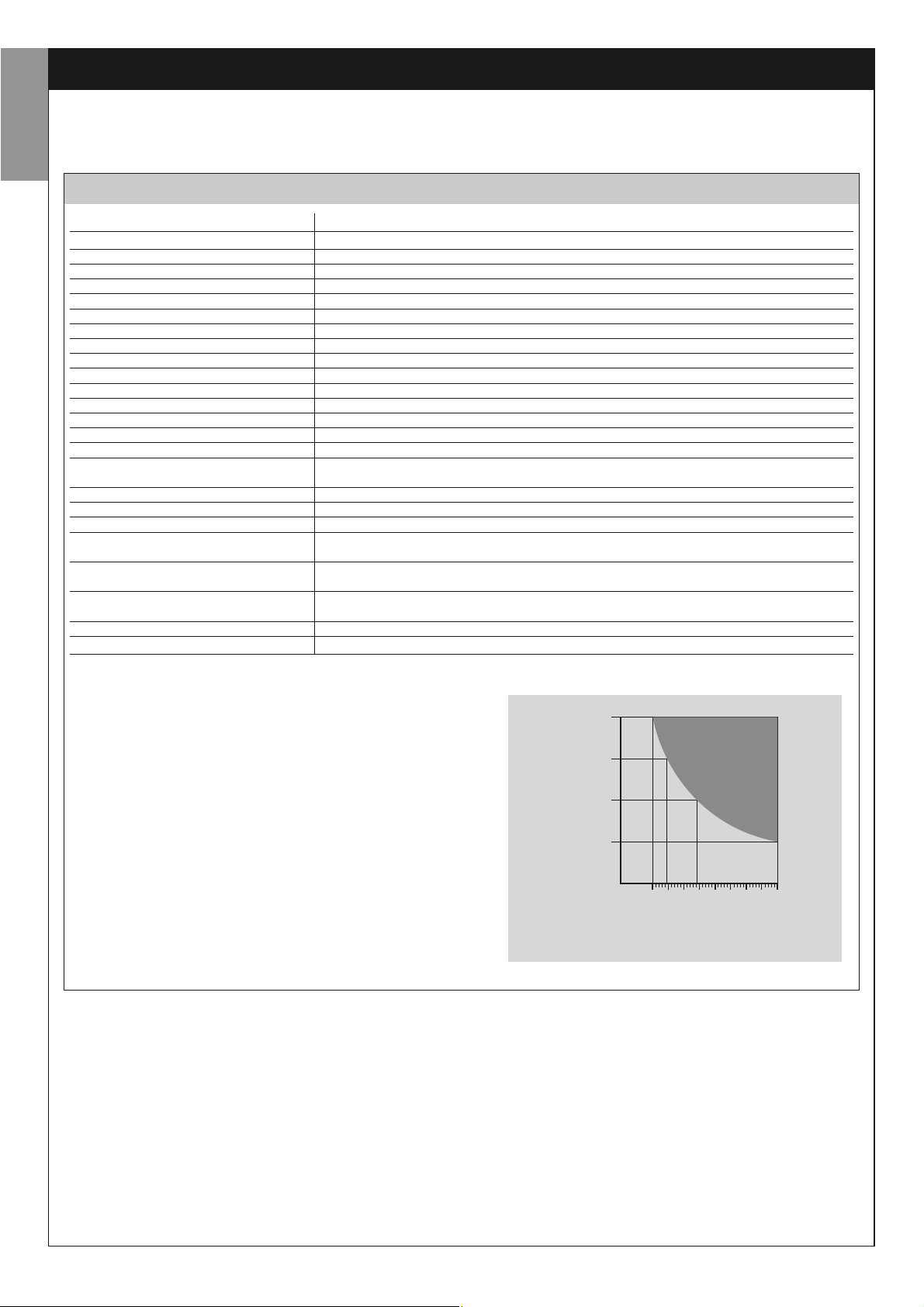
(*) Note – The estimated product durability ranges from 40.000 to
80.000 manoeuvre cycles. To calculate the probable durability of your
automation proceed as follows:
a) – evaluate the conditions of use and force levels involved on your system, for example:
• the weight and length of the garage door;
• perfect balancing of the garage door;
• maintenance conditions of the garage door hinges;
• type of leaf; Solid or with many openings;
• the presence of strong winds;
• frequency of automation use.
b) – from these values, obtain a value expressed as a percentage which,
in general, defines the greatest or smallest degree of automation wear.
c) – on the graph alongside, locate the estimated percentage (at point
"b") and read the corresponding number of manoeuvre cycles.
100 %
75 %
50 %
25 %
0 %
40.000
50.000
60.000
70.000
80.000
24 – English

MT4 TRANSMITTER
DESCRIPTION DATA
Type Radio transmitters for control of automations on gates and doors
Technology adopted AM OOK radio encoded modulation
Frequency 433.92 MHz (± 100 kHz)
Coding Rolling code with 64 Bit code (18 billion, billion combinations)
Keys 4, each key can be used for different commands of the same control unit or different control units
Radiated power 1 dBm e.r.p.
Power supply 3V +20% -40% with 1 lithium battery type CR2032
Battery lifetime
Ambient operating temperature -20°C ÷ 50°C
Use in acid, saline or potentially
explosive atmospheres
Protection class IP 40 (use in the home or protected environments)
Dimensions 40 x 70h x 8 mm
Weight 25 g
Capacity estimated at 200 m outdoors; 35 m if inside buildings (*)
(*) All radio controls are subject to interference which may alter performance levels. Therefore in the event of interference, Nice cannot guarantee the effective capacity of
their devices.
3 years, estimated on the basis of 10 commands/day of the duration of 1s at 20°C
(battery efficiency is reduced at low temperatures)
No
English
English – 25

INDICE
AVVERTENZE E PRECAUZIONI GENERALI PER LA
SICUREZZA
PASSO 1
– Operare in condizioni di sicurezza! 4
– Avvertenze per l’installazione 4
CONOSCENZA DEL PRODOTTO E PREPARAZIONE
ALL’INSTALLAZIONE
PASSO 2
2.1 - Descrizione del prodotto e destinazione d’uso 5
2.2 - Componenti utili per realizzare un impianto completo 5
PASSO 3
Verifiche preliminari all’installazione 6
3.1 - Verificare l’idoneità dell’ambiente e del portone da automatizzare 6
3.2 - Verificare i limiti d’impiego del prodotto 6
PASSO 4
4.1 - Lavori preliminari di predisposizione 7
- 4.1.1 - Impianto tipico di riferimento 7
- 4.1.2 - Stabilire la posizione dei vari componenti 7
- 4.1.3 - Stabilire con quale schema collegare i dispositivi 7
- 4.1.4 - Verificare gli attrezzi necessari per effettuare il lavoro 7
- 4.1.5 - Eseguire i lavori di predisposizione 7
4.2 - Posa dei cavi elettrici 7
COSA FARE SE... (guida alla risoluzione dei problemi) 21
ATTIVITÀ RISERVATE AD UN TECNICO QUALIFICATO
– Collegamento dell’automazione alla rete elettrica 22
– Collaudo e messa in servizio dell’automazione 22
– Smaltimento del prodotto 23
CARATTERISTICHE TECNICHE DEI VARI COMPONENTI
DEL PRODOTTO 24
Allegati: “DOCUMENTAZIONE TECNICA” I-VII
Italiano
INSTALLAZIONE: MONTAGGIO E COLLEGAMENTO DEI
COMPONENTI
PASSO 5
5.1 - Installare i componenti dell’automazione 10
5.2 - Installare la batteria tampone mod. ME 12
5.3 - Fissare l’automazione alla parete, al soffitto e al portone 13
PASSO 6
– Effettuare l’installazione e il collegamento dei dispositivi presenti nell’impianto 15
ALLACCIAMENTO DELL’ALIMENTAZIONE
PASSO 7 17
PRIMA ACCENSIONE E VERIFICA DEI COLLEGAMENTI
ELETTRICI
PASSO 8 17
PROGRAMMAZIONE DELL’AUTOMAZIONE
PASSO 9
9.1 - Memorizzazione del trasmettitore mod. MT4 18
9.2 - Memorizzazione delle posizioni di finecorsa in “Apertura” e
“Chiusura” del portone 18
REGOLAZIONI E ALTRE FUNZIONI OPZIONALI
10 - Regolazione del funzionamento dell’automazione 19
11 - Memorizzazione di un nuovo trasmettitore con la procedura ‘in vicinanza’
della Centrale 19
12 - Cancellazione dei dati presenti nella memoria della Centrale 19
Italiano – 3
AVVERTENZE E PRECAUZIONI GENERALI PER LA SICUREZZA
PASSO 1
OPERARE IN CONDIZIONI DI SICUREZZA!
Attenzione – per la sicurezza delle persone è importante
rispettare queste istruzioni.
Attenzione – Istruzioni importanti per la sicurezza: quindi,
conservare queste istruzioni.
La progettazione, la fabbricazione dei dispositivi che compongono il
prodotto e le informazioni contenute nel presente manuale rispettano pienamente le normative vigenti sulla sicurezza. Ciò nonostante,
Italiano
un’installazione e una programmazione errata possono causare gravi ferite alle persone che eseguono il lavoro e a quelle che useranno
l’impianto. Per questo motivo, durante l’installazione, è importante
seguire attentamente tutte le istruzioni riportate in questo manuale.
Non procedere con l’installazione se si hanno dubbi di qualunque natura e
richiedere eventuali chiarimenti al Servizio Assistenza Moovo.
Se questa è la prima volta che vi apprestate a realizzare un’automazione
per portoni da garage (“sezionali” o “basculanti”), vi consigliamo di dedicare un po’ del vostro tempo alla lettura del presente manuale. Ciò è preferibile farlo prima di iniziare il lavoro, senza avere fretta di iniziare con le
operazioni pratiche.
Inoltre, tenere a portata di mano tutti i dispositivi che compongono il prodotto affinché possiate leggere, provare e verificare (ad esclusione delle
fasi di programmazione) tutte le informazioni contenute nel manuale.
Nel leggere questo manuale occorre prestare molta attenzione alle
istruzioni contrassegnate con il simbolo:
Questi simboli indicano argomenti che possono essere fonte potenziale di pericolo e pertanto, le operazioni da svolgere devono essere
realizzate esclusivamente da personale qualificato ed esperto, nel
rispetto delle presenti istruzioni e delle norme di sicurezza vigenti sul
proprio territorio.
– eseguire l’analisi dei rischi che deve comprendere anche l’elenco dei
requisiti essenziali di sicurezza riportati nell’ “allegato I della Direttiva Mac-
chine”, indicando le relative soluzioni adottate. Si ricorda che l’analisi dei
rischi è uno dei documenti che costituiscono il “fascicolo tecnico” dell’automazione. Questo dev’essere compilato da un installatore professionista.
Considerando le situazioni di rischio che possono verificarsi durante
le fasi di installazione e di uso del prodotto è necessario installare
l’automazione osservando le seguenti avvertenze:
– non eseguire modifiche su nessuna parte dell’automatismo se non quelle previste nel presente manuale. Operazioni di questo tipo possono solo
causare malfunzionamenti. Il costruttore declina ogni responsabilità per
danni derivanti da prodotti modificati arbitrariamente.
– evitare che le parti dei componenti dell’automazione possano venire
immerse in acqua o in altre sostanze liquide. Durante l'installazione evitare che i liquidi possano penetrare all'interno del motoriduttore e dei dispositivi presenti.
– se sostanze liquide penetrano all’interno delle parti dei componenti
dell’automazione, scollegare immediatamente l’alimentazione elettrica e
rivolgersi al Servizio Assistenza Moovo. L’utilizzo dell’automazione in tali
condizioni può causare situazioni di pericolo.
– non mettere i vari componenti dell’automazione vicino a fonti di calore
né esporli a fiamme libere. Tali azioni possono danneggiarli ed essere causa di malfunzionamenti, incendio o situazioni di pericolo.
– tutte le operazioni che richiedono l’apertura del guscio di protezione dei
vari componenti dell’automazione, devono avvenire con la Centrale scollegata dall’alimentazione elettrica. Se il dispositivo di sconnessione non è
a vista, apporvi un cartello con la seguente dicitura: “ATTENZIONE!
MANUTENZIONE IN CORSO”.
– il prodotto non può essere considerato un efficace sistema di protezione
contro l’intrusione. Se desiderate proteggervi efficacemente, è necessario
integrare l’automazione con altri dispositivi.
– la Centrale deve essere collegata ad una linea di alimentazione elettrica
dotata di messa a terra di sicurezza.
– il prodotto può essere utilizzato esclusivamento dopo che è stata effettuata la “messa in servizio” dell’automazione, come previsto nel paragrafo
“Collaudo e messa in servizio dell’automazione” riportato nel riquadro
“Attività riservate ad un tecnico qualificato”.
– Il materiale dell’imballaggio di tutti i componenti dell’automazione deve
essere smaltito nel pieno rispetto della normativa presente a livello locale.
AVVERTENZE PER L’INSTALLAZIONE
Secondo la più recente legislazione europea, la realizzazione di un
portone da garage deve rispettare le norme previste dalla Direttiva
98/37/CE (Direttiva Macchine) e in particolare, le norme EN 12445;
EN 12453; EN 12635 e EN 13241-1, che consentono di dichiarare la
presunta conformità dell’automazione.
il collegamento definitivo dell’automatismo alla rete elettrica, il collaudo dell’impianto, la sua messa in servizio e la manutenzione
periodica devono essere eseguiti da personale qualificato ed esperto, rispettando le istruzioni riportate nel riquadro “Attività riservate
ad un tecnico qualificato”. Inoltre, egli dovrà farsi carico di stabilire
anche le prove previste in funzione dei rischi presenti e dovrà verificare il rispetto di quanto previsto da leggi, normative e regolamenti:
in particolare, il rispetto di tutti i requisiti della norma EN 12445 che
stabilisce i metodi di prova per la verifica degli automatismi per portoni da garage.
Invece, riguardo i lavori di predisposizione iniziale, d’installazione e
di programmazione, questi possono essere effettuati anche da personale non particolarmente qualificato, purché vengano rispettate
scrupolosamente e nell’ordine progressivo indicato, tutte le istruzioni riportate in questo manuale e, in particolare, le avvertenze di questo PASSO 1.
Prima di iniziare l’installazione, effettuare le seguenti analisi e
verifiche:
– verificare che i singoli dispositivi destinati all’automazione siano adatti
all’impianto da realizzare. Al riguardo, controllare con particolare attenzione i dati riportati nel capitolo “Caratteristiche tecniche”. Non effettuare
l’installazione se anche uno solo di questi dispositivi non è adatto all’uso.
– verificare se i dispositivi presenti nel kit sono sufficienti a garantire la
sicurezza dell’impianto e la sua funzionalità.
In considerazione di ciò,
4 – Italiano
CONOSCENZA DEL PRODOTTO E PREPARAZIONE ALL’INSTALLAZIONE
PASSO 2
2.1 – DESCRIZIONE DEL PRODOTTO E DESTINAZIONE
D’USO
In generale, l’insieme dei dispositivi che compongono il presente prodotto
è destinato ad automatizzare un portone da garage ad uso residenziale
(fig. 1). Questo può essere di tipo “sezionale” o di tipo “basculante”; il
basculante può essere a sua volta debordante (durante l’apertura il portone sporge all’esterno) o non debordante ed essere provvisto di molle o
contrappesi.
In particolare, il presente kit è destinato all’automatizzazione esclusiva di
un portone “sezionale”. Quindi, per poter automatizzare un portone
“basculante” occorre montare un apposito braccio oscillante (mod. MA,
accessorio non presente nella confezione).
Qualsiasi altro uso diverso da quello descritto e in condizioni am bientali diverse da quelle riportate nel PASSO 3 è da considerarsi
improprio e vietato!
Il presente prodotto (TS432B - TS432Be - TS432BH - TS432BeH) com-
posto da un motoriduttore elettromeccanico con un motore in corrente
continua a 24V, una guida, una catena e un carrello di traino. Nel motoriduttore è presente anche una Centrale di comando.
La Centrale è formata da una scheda elettronica, una luce di cor te sia/segnalazione e un ricevitore radio incorporato, più l’antenna, che riceve i comandi inviati da un trasmettitore.
La Centrale è in grado di gestire diversi tipi di manovre, ciascuna programmabile e utilizzabile secondo le proprie esigenze.
Inoltre, sono disponibili varie funzioni speciali che permettono di personalizzare il funzionamento dell’automazione.
L’automazione è predisposta per essere utilizzata con vari accessori che
ne aumentano la funzionalità ne garantiscono la sicurezza. In particolare,
la Centrale può memorizzare fino a 150 tasti di trasmettitori mod. MT4 e
fino a 4 coppie di fotocellule, mod. MPQ.
Il prodotto funziona tramite alimentazione elettrica di rete e, in caso di
interruzione dell’energia elettrica (black-out), consente di muovere ‘a
mano’ il portone, sbloccando il carrello di traino con un apposito cordino
o con uno sblocco posto all’esterno (mod. MU, accessorio non presente
nella confezione).
È comunque possibile aprire il portone anche sfruttando la batteria tampone (modello ME) se questa è presente nell’impianto.
2.2 – COMPONENTI UTILI PER REALIZZARE
UN IMPIANTO COMPLETO
La fig. 2 mostra tutti i componenti utili per realizzare un impianto completo, tipo quello mostrato in fig. 8.
Alcuni componenti riportati in fig. 2 sono opzionali e possono
non essere presenti nella confezione.
Elenco dei componenti utili:
[a] - motoriduttore elettromeccanico
[b] - guida per il carrello in 3 pezzi + staffe di giunzione
(solo per il mod. TS432B e TS432Be)
[c] - guida intera (solo per il mod. TS432BH e TS432BeH)
[d] - staffe per fissare il motoriduttore al soffitto
[e] - staffa per fissare la guida alla parete
[f] - fermo meccanico per l’arresto del carrello nel finecorsa
[g] - rinvio della catena
[h] - catena di traino
[i] - carrello di traino
[l] - cordino e pomello per lo sblocco dell’automatismo
[m]- asta di traino del portone (solo per portoni sezionali
[n] - staffa per collegare l’asta di traino al portone
[o] - braccio oscillante e sua asta di traino
(mod. MA, solo per portoni basculanti
[p] - coppia di fotocellule (per parete) mod. MPQ
[q] - trasmettitore (portatile) mod. MT4
[r] - tastiera di comando via radio mod. MKR (per parete)
[s] - due batterie tampone mod. ME
(solo per il mod. TS432Be e TS432BeH)
[t] - minuteria metallica (viti, rondelle, ecc.)
[u] - kit di sblocco esterno mod. MU
(
) Nota – Le viti necessarie al fissaggio dei componenti sul muro non
*
sono comprese nella confezione. La loro tipologia dipende dal materiale e
dallo spessore del muro nel quale devono essere inserite.
AVVERTENZA!
)
)
*
Italiano
1
SEZIONALE DEBORDANTE NON DEBORDANTE
Italiano – 5
2
ab c d
ef ghi
Italiano
lmnop
qr s t
PASSO 3
VERIFICHE PRELIMINARI ALL’INSTALLAZIONE
Prima di procedere all’installazione, è necessario verificare l’integrità dei
componenti del prodotto, l’adeguatezza del modello scelto e l’idoneità
dell’ambiente destinato all’installazione.
IMPORTANTE – Il motoriduttore non può automatizzare un portone
che non sia già efficiente e sicuro. Inoltre, non può risolvere i difetti
causati da una sbagliata installazione o da una cattiva manutenzione
del portone stesso.
3.1 – VERIFICARE L’IDONEITÀ DELL’AMBIENTE E DEL
PORTONE DA AUTOMATIZZARE
• Nel caso di automatizzazione di un portone basculante debordante,
verificare che il suo movimento non ingombri strade o marciapiedi pubblici.
• Verificare che la struttura meccanica del portone sia adatta ad essere
automatizzata e conforme alle norme vigenti sul territorio.
• Verificare la robustezza della struttura meccanica del portone controllan-
do che non vi siano rischi di fuoriuscita dalle guide.
• Muovendo manualmente il portone in Apertura e Chiusura, verificare che
il movimento avvenga con attrito uguale e costante in ogni punto della sua
corsa (non devono esserci momenti di maggiore sforzo).
• Verificare che il portone sia ben bilanciato: cioè, se questo viene lascia-
to fermo (manualmente) in una posizione qualsiasi, non deve muoversi.
• Verificare che lo spazio intorno all’automazione consenta una manovra
manuale di sblocco, facile e sicura.
• Verificare che le superfici scelte per l’installazione dei vari dispositivi siano solide e possano garantire un fissaggio stabile.
• Verificare che ciascun dispositivo da installare sia collocato in una posizione protetta e al riparo da urti accidentali.
• Verificare che le superfici scelte per il fissaggio delle fotocellule siano piane e permettano un corretto allineamento tra le fotocellule stesse.
3.2 – VERIFICARE I LIMITI D’IMPIEGO DEL PRODOTTO
Per stabilire l’idoneità del prodotto rispetto alle peculiarità del vostro portone e alle specificità del contesto da automatizzare, è necessario effettuare le verifiche riportate di seguito e controllare la loro conformità sia con
i dati presenti in questo paragrafo, sia con i dati tecnici del capitolo
“Caratteristiche tecniche del prodotto”.
• Verificare che il portone abbia dimensioni e peso rientranti nei seguenti
limiti d’impiego:
modello TS432B e TS432Be
– Portoni sezionali: larghezza massima 350 cm; altezza massima 212
cm; forza massima per la movimentazione 500 N.
– Portoni basculanti debondarti: larghezza massima 350 cm; altezza
massima 260 cm; forza massima per la movimentazione 500 N.
– Portoni basculanti non debondarti: larghezza massima 350 cm;
altezza massima 212 cm; forza massima per la movimentazione 500 N.
modello TS432BH e TS432BeH
– Portoni sezionali: larghezza massima 350 cm; altezza massima 240
cm; forza massima per la movimentazione 500 N.
– Portoni basculanti debondarti: larghezza massima 350 cm; altezza
massima 280 cm; forza massima per la movimentazione 500 N.
– Portoni basculanti non debondarti: larghezza massima 350 cm;
altezza massima 220 cm; forza massima per la movimentazione 500 N.
u
6 – Italiano
 Loading...