

Moovo MPQ User Manual
générer des incendies ou des secousses électriques.
• Vérifier périodiquement le fonctionnement correct des photocellules, en
effectuant les contrôles décrits au chapitre “Maintenance”.
7 - MAINTENANCE
Exécuter les opérations de maintenance tous les 6 mois (minimum), cellesci consistent à : a - vérifier toute présence éventuelle d’humidité, oxydation
ou autre ; b - nettoyer l’enveloppe extérieure et les lentilles ; c - effectuer un
nouveau test comme décrit au chapitre “Test”.
Les photocellules sont conçues pour fonctionner pendant au moins 10 ans
dans des conditions normales ; après ce délai, il convient d’intensifier la fréquence des interventions de maintenance.
CARACTERISTIQUES TECHNIQUES
Type de produit : détecteur de présence pour automatismes sur portes
et portillons (type D conformément à la norme EN 12453) composé d’un
transmetteur et d’un récepteur. Technologie adoptée : iinterpolation
optique directe entre TX et RX, avec rayon infrarouge modulé. Alimenta-
tion : sélection avec pontage : “12 V” = 12 Vac/dc (plages 8-16 Vac, 9-17
Vdc ) ; sélection avec pontage : “24 V” = 24 Vac/dc (plages 19-28 Vac, 1735 Vdc). Courant absorbé : 20 mA (TX), 25 mA (RX), 45 mA (en couple).
Capacité de détection : objets opaques placés sur l’axe optique entre
TX et RX, de dimensions supérieures à 50 mm et vitesse inférieure à 1,6
m/s. Angle de transmission et de réception : +/- 15° environ (valeur
relevée à 50% de la portée). Portée utile : 8 m (le dispositif peut signaler
un obstacle même dans des conditions météorologiques particulièrement
adverses). Portée maximale : 20 m (portée garantie dans des condi-
tions optimales). Utilisation en atmosphère acide, saline potentielle-
ment explosive : NON. Montage : vertical, au mur ou sur colonne
MPT5. Degré de protection conteneur : IP44. Température d’exer-
cice : -20° ÷ 50°C. Dimensions / Poids (couple) : 50 x 85h x 35 mm /
140 g.
ELIMINATION DU PRODUIT
Ce produit fait partie intégrante de l’automatisation et par conséquent, il doit être éliminé avec celle-ci.
Tout comme pour les opérations d’installation, à la fin de la vie utile de ce
produit, les opérations d’élimination doivent être effectuées par du personnel qualifié.
Ce produit se compose de différents types de matériaux : certains peuvent
être recyclés, d’autres doivent être éliminés. Informez-vous sur les systèmes de recyclage ou d’élimination prévus par les règlements en vigueur
sur votre territoire pour ce type de produit.
Attention! – certaines parties du produit peuvent contenir des substances
polluantes ou dangereuses qui, si elles sont jetées dans l’environnement,
peuvent provoquer des effets nocifs sur l’environnement lui-même et sur la
santé des personnes.
Comme indiqué par le symbole ci-contre, il est interdit de jeter
ce produit dans les déchets domestiques. Recourir donc au
“ramassage séparé” pour l’élimination, selon les méthodes
prévues par les règlements en vigueur sur votre territoire, ou
remettre le produit au vendeur au moment de l’achat d’un
nouveau produit similaire.
Attention! – les règlements en vigueur au niveau local peuvent prévoir de
lourdes sanctions dans le cas d’élimination abusive de ce produit.
TECHNICAL FEATURES
Product type: obstacle detector for gates and doors (D type
according to EN 12453 standard) made with one transmitter and one
receiver. Technology used: direct optical interpolation between TX
and RX, with modulated infrared rays. Power: selection using
jumper: “12 V” = 12 Vac/dc (limit 8-16 Vac, 9-17 Vdc); selection using
jumper: “24 V” = 24 Vac/dc (limit 19-28 Vac, 17-35 Vdc). Absorbed
current: 20 mA (TX), 25 mA (RX), 45 mA (together). Detection
capacity: matt objects positioned on the optical axis between TX and
RX, with dimensions larger than 50 mm and speed lower than 1.6 m/s.
Transmission and receiver angle: about +/- 15° (value detected at
50% of the capacity). Useful capacity: 8 m (the device can also
detect an obstacle in particularly adverse meteorological conditions).
Maximum capacity: 20 m (guaranteed capacity in optimal conditions).
Use in acidic, saline and potentially explosive atmosphere: NO.
Mounting: vertically, on wall or on MPT5 column. Level of con-
tainer protection: IP44. Working temperature: -20° ÷ 50°C.
Dimensions / Weight (pair): 50 x 85h x 35 mm / 140 g.
PRODUCT DISPOSAL
This product is an integral part of the automation and therefore
has to be disposed with it.
As for installation, at the end of the life-span of this product, it must be
dismantled by specialised staff.
This product is made with various types of material: some can be recycled, others have to be disposed of. Acquaint yourself with your territory’s rules for recycling or disposing of this type of product.
Attention! – some parts of the product may contain pollutants or dangerous substances which, if dispersed into the environment, could
have dangerous effects for the environment itself and on human health.
As indicated by the symbol on the side, it is prohibited to
dispose of this product as domestic refuse.
Therefore, according to the rules in force in your territory,
carry out “separate collection” for disposal, or return the
product to the dealer when purchasing a new one.
Attention! – local regulations in force may envision heavy sanctions in
case of unauthorised disposal of this product.
CE DECLARATION OF CONFORMITY
MPQ is produced by NICE S.p.a. (TV) I; MOOVO is a commercial trademark owned
by Nice S.p.a.
Note: The content of this declaration corresponds to that in the latest available
version of the official document deposited with Nice Spa, before going to press.
This text has been adapted for editorial reasons.
Number: 289/MPQ Revision: 0
The undersigned Managing Director, Lauro Buoro , declares under his own respon-
sibility that the product – product name: NICE s.p.a.; address: via Pezza Alta, 13
- Z.I. Rustignè, 31046 Oderzo (TV) Italy; type: relay photocell series “MOOVO”;
model: MPQ; accessory: MPT5, – is in compliance with the European Community Directives, as modified by 93/68/EEC Directive by the Council, dated 22 July
1993:
• 2004/108/EEC (ex Directive 89/336/EEC) DIRECTIVE 2004/108/CE OF THE
EUROPEAN PARLIAMENT AND COUNCIL dated 15 December 2004, regarding
the harmonisation of the legislations of the Member States relating to the electro-magnetic compatibility and which abrogates the 89/336/EEC Directive,
according to the following harmonised standards: EN 61000-6-2:2005;
EN 61000-6-3:2001+A11:2004
Oderzo, 5 May 2008 Lauro Buoro
(Managing Director)
ENGLISH
1 - AVVERTENZE
1.1 - Avvertenze per la sicurezza
• ATTENZIONE! – Il presente manuale contiene importanti istruzioni e
avvertenze per la sicurezza delle persone. Un’installazione errata può
causare gravi ferite alle persone. Pertanto, prima di iniziare il lavoro è
necessario leggere attentamente tutte le parti del manuale e, in caso di
dubbi, chiedere chiarimenti al Servizio Assistenza Moovo.
• ATTENZIONE! – Tutte le operazioni di installazione, di collegamento, di programmazione e di manutenzione del prodotto devono es sere effettuate esclusivamente da un tecnico qualificato e competente, rispettando le leggi, le normative, i regolamenti locali e le is truzioni riportate in questo manuale.
• ATTENZIONE! – Istruzioni importanti: conservare questo manuale
per eventuali interventi futuri di programmazione, manutenzione e di
smaltimento del prodotto.
Avvertenze particolari sull’idoneità all’uso di questo prodotto in relazione alla Direttiva “Compatibilità Elettromagnetica” 89/336/CEE e
successive modifiche 92/31/CEE e 93/68/CEE.
Questo prodotto è stato sottoposto a prove di compatibilità elettromagnetica in situazioni d’uso critiche, nelle configurazioni previste in questo
manuale e in abbinamento con gli articoli presenti nel catalogo prodotti
Moovo.
Con configurazioni o prodotti non previsti, la compatibilità elettromagnetica
non è garantita; pertanto l’uso del prodotto è possibile soltanto dopo aver
verificato la sua piena rispondenza ai requisiti previsti dalla direttiva.
1.2 - Avvertenze per l’installazione
Attenzione! – Il sistema deve funzionare esclusivamente per interpo-
lazione diretta
tra TX ed RX: è vietato il funzionamento per riflessione.
• Non smontare il prodotto oltre le operazioni previste in questo manuale.
Operazioni non previste possono causare malfunzionamenti e il costruttore declina ogni re sponsabilità per danni derivanti da prodotti modificati
arbitrariamente.
• Durante l’installazione maneggiare con cura il prodotto evitando schiacciamenti, urti, cadute, contatti con qualsiasi liquido, fonti di calore e fiamme libere. Queste situazioni possono danneggiare il prodotto ed essere
causa di malfunzionamento o pericolo. In questi casi scollegare immediatamente l’alimentazione, sospendere l’installazione e rivolgersi al Servizio
Assistenza Moovo.
• Il materiale dell’imballaggio del prodotto deve essere smaltito nel pieno
rispetto della normativa locale.
2 - DESCRIZIONE DEL PRODOTTO E DESTINAZIONE D’USO
Questo prodotto è una coppia di fotocellule a relè destinata agli impianti di
automazione per porte, cancelli, portoni da garage e similari. ATTENZIO-
NE! – Qualsiasi altro uso diverso da quello descritto è da considerarsi
improprio e vietato!
La coppia è formata da una fotocellula che trasmette (TX) e una che riceve (RX), ciascuna identificata con un’etichetta all’interno del coperchio.
Nell’insieme sono un dispositivo ausiliario alla sicurezza in quanto permettono di rilevare la presenza di un ostacolo sulla traiettoria che unisce
TX ed RX. Possono essere installate su una parete o sulle colonne MPT5
(accessorio opzionale).
3 - VERIFICHE PRELIMINARI ALL’INSTALLAZIONE
• Verificare sulla Centrale dell’automatismo, che la tensione di alimentazione presente sui morsetti dedicati, sia compatibile con i dati riportati nel
capitolo “Caratteristiche tecniche”.
• Verificare che ciascuna fotocellula sia collocata in una posizione protetta,
al riparo da urti accidentali e che permetta una facile manutenzione.
• Verificare che la superficie prescelta per l’installazione garantisca un fissaggio stabile e non trasmetta vibrazioni alla fotocellula.
Limiti d’impiego
Le fotocellule possono essere collegate esclusivamente a Centrali con
ingressi “Foto” di tipo tradizionale. Ulteriori limiti d’impiego sono riportati nel
capitolo “Caratteristiche tecniche”.
4 - INSTALLAZIONE E COLLEGAMENTI
Attenzione! • Prima di effettuare i collegamenti elettrici o altre operazioni
che richiedono l’apertura del guscio di protezione del prodotto, è necessario scollegare l’impianto dall’alimentazione elettrica e dalla batteria tampone
(se è presente). Inoltre, se il di spositivo di sconnessione non è in vista,
attaccare su questo un cartello con la dicitura “ATTENZIONE! MANUTENZIONE IN CORSO”. • Rispettare scrupolosamente i collegamenti indicati.
Un collegamento errato può provocare guasti o situazioni di pericolo.
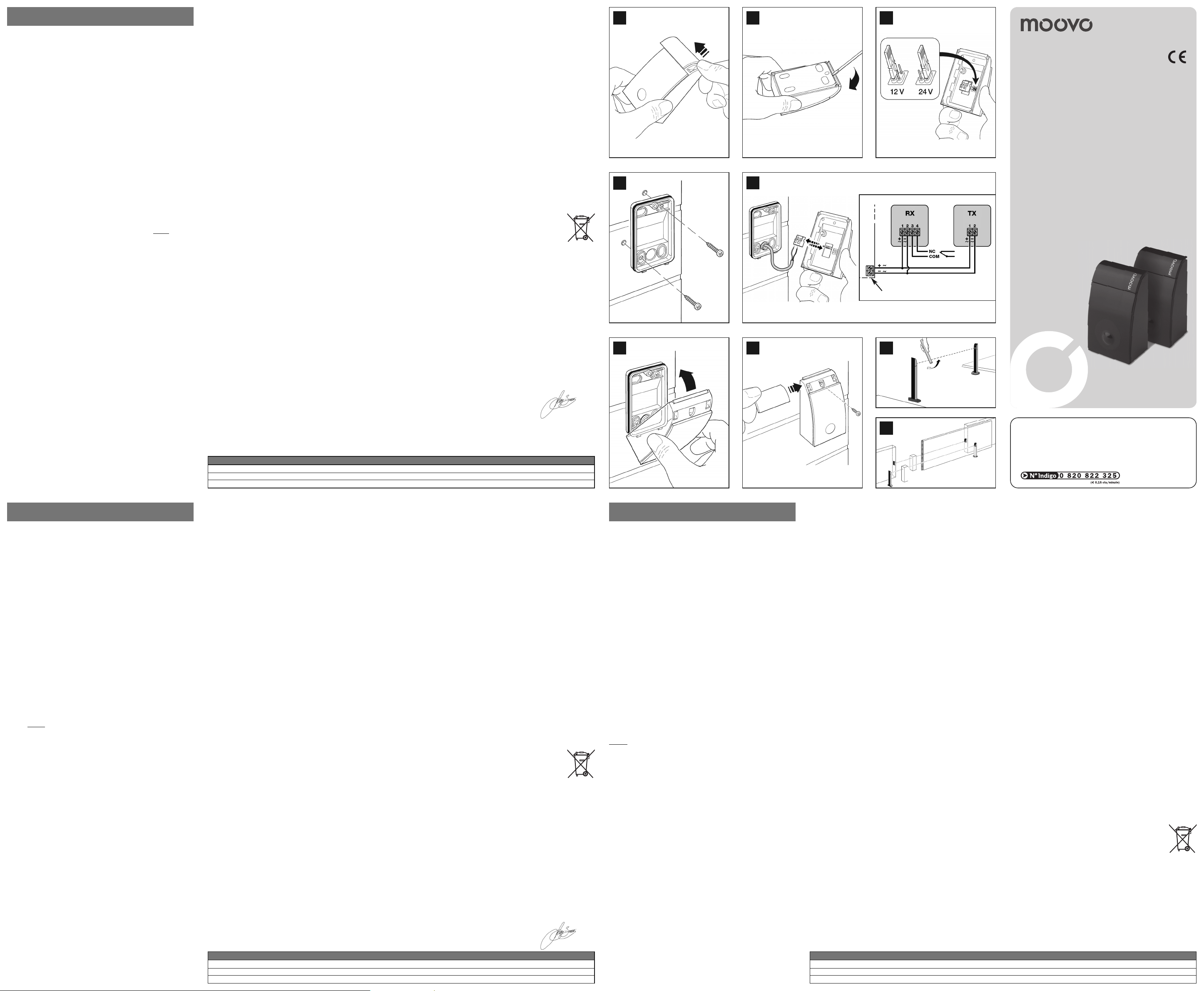
Procedere nel modo seguente:
01 - Aprire le fotocellule (fig. 1-2); 02 - verificare il tipo di alimentazione for-
nita dalla Centrale dell’automatismo; 03 - spostare il ponticello elettrico del
TX e dell’RX, nella posizione adatta a selezionare la stessa alimentazione
presente nella Centrale (fig. 3); 04 - fissare sulla parete il coperchio posteriore delle fotocellule (fig. 4); 05 - eseguire i collegamenti elettrici in base
alla funzione desiderata, seguendo le istruzioni riportate nel manuale della
Centrale e nello schema di fig. 5; 06 - rimontare la parte anteriore delle
fotocellule (fig. 6-7).
5 - COLLAUDO
Ogni singolo componente dell’automatismo richiede una fase specifica di
collaudo. Per le fotocellule eseguire la seguente procedura:
01 - Verificare che siano state rispettate rigorosamente tutte le istruzioni
riportate in questo manuale. 02 - Alimentare la coppia di fotocellule e verificare il loro allineamento confrontando lo stato del Led della fotocellula RX
(acceso o spento), con la Tabella 1. 03 - Se necessario, migliorare l’allinea-
mento orientando le fotocellule fino a quando il Led si spegne. 04 - Verificare l’efficienza delle fotocellule e, in particolare, l’assenza di interferenze con
altri dispositivi (ad esempio, un’altra coppia di fotocellule installata nelle vicinanze), interrompendo l’asse ottico tra le due fotocellule con un cilindro del
diametro di 5 cm (prima vicino al TX, poi vicino all’RX e infine al centro tra i
due – vedere fig.8). Quindi, verificare che le fotocellule intervengano in tutti
i casi, passando dallo stato attivo a quello di allarme e viceversa; infine, che
provochino nella Centrale l’azione prevista sull’automatismo (ad esempio,
nella manovra di chiusura, che provochino l’inversione del movimento). 05
- Verificare la corretta rilevazione dell’ostacolo applicando la norma EN
12445, che prevede l’uso di un parallelepipedo di test (700 x 300 x 200
mm), con 3 lati in colore nero opaco e 3 lati in colore bianco lucido o a
specchio (vedere fig. 9).
6 - AVVERTENZE PER L’USO
• Le fotocellule non sono un dispositivo di sicurezza ma soltanto un dispositivo ausiliario alla sicurezza; nonostante siano costruite con tecnologia
affidabile, in situazioni estreme possono subire malfunzionamenti o guastarsi e, in certi casi, il guasto potrebbe non essere subito evidente. Per
questi motivi, e comunque per buona regola,
- il transito è consentito solo se il cancello o portone è completamente
aperto e con le ante ferme.
- È ASSOLUTAMENTE VIETATO transitare mentre il cancello o portone
si sta chiudendo!
• Prima di procedere alla pulizia del prodotto, sbloccare il motoriduttore
come descritto nel suo manuale istruzioni. Questo impedisce l’azionamento involontario dell’automazione.
• Per la pulizia del prodotto, utilizzare un panno morbido e umido. Impor-
tante – non utilizzare liquidi contenenti alcool, benzene, diluenti o altre
sostanze infiammabili: questi possono danneggiare il prodotto e generare
incendi o scosse elettriche.
• Verificare periodicamente il corretto funzionamento delle fotocellule, effettuando i controlli descritti nel capitolo “Manutenzione”.
7 - MANUTENZIONE
Eseguire la manutenzione ogni 6 mesi (minimo), effettuando le seguenti
operazioni: a - verifica di eventuali presenze di umidità, ossidazione, o altro;
b - pulizia dell’involucro esterno e delle lenti; c - nuovo collaudo come de scritto nel capitolo “Collaudo”.
Le fotocellule sono studiate per funzionare in condizioni normali almeno 10
anni; trascorso questo periodo è opportuno intensificare la frequenza degli
interventi di manutenzione.
CARATTERISTICHE TECNICHE
Tipo di prodotto: rilevatore di presenza per automatismi su cancelli e
portoni (tipo D secondo norma EN 12453) composto da un trasmettitore e
un ricevitore. Tecnologia adottata: interpolazione ottica diretta tra TX ed
RX, con raggio infrarosso modulato. Alimentazione: selezione con ponticello: “12 V” = 12 Vac/dc (limiti 8-16 Vac, 9-17 Vdc); selezione con ponticello: “24 V” = 24 Vac/dc (limiti 19-28 Vac, 17-35 Vdc). Corrente assor-
bita: 20 mA (TX), 25 mA (RX), 45 mA (in coppia). Capacità di rilevamento: oggetti opachi posti sull’asse ottico tra TX ed RX, con dimensioni mag-
giori di 50 mm e velocità minore di 1,6 m/s. Angolo di trasmissione e di
ricezione: +/- 15° circa (valore rilevato al 50% della portata). Portata utile: 8 m (il dispositivo può segnalare un ostacolo anche in caso di condizio-
ni meteorologiche particolarmente avverse). Portata massima: 20 m
(portata garantita in condizioni ottimali). Utilizzo in atmosfera acida,
salina potenzialmente esplosiva: NO. Montaggio: in verticale, a pare-
te o su colonna MPT5. Grado di protezione contenitore: IP44. Tem-
peratura di esercizio: -20° ÷ 50°C. Dimensioni / Peso (coppia): 50 x
85h x 35 mm / 140 g.
SMALTIMENTO DEL PRODOTTO
Questo prodotto è parte integrante dell'automazione e, dunque, deve
essere smaltito insieme con essa.
Come per le operazioni d'installazione, anche al termine della vita di questo
prodotto, le operazioni di smantellamento devono essere eseguite da personale qualificato.
Questo prodotto è costituito da vari tipi di materiali: alcuni possono essere
riciclati, altri devono essere smaltiti. Informatevi sui sistemi di riciclaggio o
smaltimento previsti dai regolamenti vigenti sul vostro territorio, per questa
categoria di prodotto.
Attenzione! – alcune parti del prodotto possono contenere sostanze inquinanti o pericolose che, se disperse nell’ambiente, potrebbero provocare
effetti dannosi sull'ambiente stesso e sulla salute umana.
Come indicato dal simbolo a lato, è vietato gettare questo prodotto nei rifiuti domestici. Eseguire quindi la “raccolta separata” per lo smaltimento, secondo i metodi previsti dai regolamenti vigenti sul vostro territorio, oppure riconsegnare il prodotto al venditore nel momento dell'acquisto di un nuovo prodotto equivalente.
Attenzione! – i regolamenti vigenti a livello locale possono prevedere
pesanti sanzioni in caso di smaltimento abusivo di questo prodotto.
DICHIARAZIONE DI CONFORMITÁ CE
MPQ è prodotto da NICE S.p.a. (TV) I; MOOVO è un marchio commerciale di proprietà
di Nice S.p.a.
Nota: Il contenuto di questa dichiarazione corrisponde a quanto dichiarato nell’ultima revisione disponibile, prima della stampa di questo manuale, del documento ufficiale depositato presso la sede di Nice Spa. Il presente testo è stato riadattato per motivi editoriali.
Numero: 289/MPQ Revisione: 0
Il sottoscritto Lauro Buoro in qualità di Amministratore Delegato, dichiara sotto la propria
responsabilità che il prodotto – nome produttore: NICE s.p.a.; indirizzo: via Pezza
Alta, 13 - Z.I. Rustignè, 31046 Oderzo (TV) Italia; tipo: fotocellula a relè serie “MOOVO”;
modelli: MPQ; accessori: MPT5, – risulta conforme a quanto previsto dalle seguenti
direttive comunitarie, così come modificate dalla Direttiva 93/68/CEE del consiglio del
22 Luglio 1993:
• 2004/108/CEE (ex direttiva 89/336/CEE) DIRETTIVA 2004/108/CE DEL PARLAMENTO EUROPEO E DEL CONSIGLIO del 15 dicembre 2004, concernente il ravvicinamento delle legislazioni degli Stati membri relative alla compatibilità elettromagnetica e
che abroga la direttiva 89/336/CEE,
secondo le seguenti norme armonizzate: EN 61000-6-2:2005; EN 61000-63:2001+A11:2004
Oderzo, 5 Maggio 2008 Lauro Buoro
(Amministratore Delegato)
ITALIANO FRANÇAIS
Tabella 1
Stato del Led Significato Stato uscita Azione
Sempre spento Segnale OK = Nessun ostacolo Attivo Nessuna (tutto Ok!)
Sempre acceso Segnale zero = Presente ostacolo Allarme Rimuovere ostacolo o migliorare l’allineamento
Tableau 1
Etat de la Led Signification Etat sortie Action
Toujours éteinte Signal OK = Aucun obstacle Activé Aucune (tout Ok!)
Toujours allumée Signal zéro = Présence d’un obstacle Alarme Enlever l’obstacle ou améliorer l’alignement
MPQ
Pair of photocells
5
1 2
6 7
4
Oderzo TV, Italy
Tel. +39 0422 20 21 09
Fax +39 0422 85 35 85
www.moovo.com
Moovo is a commercial
trademark owned by
Nice S.p.a.
Codice: IST260.4854 - Rev. 00 del 15-07-2008
EN Installation and use instructions and
warnings
IT Istruzioni ed avvertenze per
l’installazione e l’uso
FR Instructions et avertissements pour
l’installation et l’utilisation
ES Instrucciones y advertencias para la
instalación y el uso
DE Anweisungen und Hinweise für die
Installation und die Bedienung
PL Instrukcje instalacji i użytkowania i
ostrzeżenia
NL Aanwijzingen en aanbevelingen voor
installering en gebruik
Hotline technique exclusivement pour la France:
3
12V / 24V
8
9
Table 1
State of LED Meaning Exit state Action
Always off Signal OK = No obstacle Active None (everything Ok!)
Always on Zero signal = Obstacle present Alarm Remove obstacle or improve alignment
1 - MISES EN GARDE
1.1 - Mises en garde de sécurité
• ATTENTION! – Le présent manuel fournit d’importantes instructions
et mises en garde sur la sécurité des personnes. Une installation erronée peut causer de graves blessures aux personnes. Par conséquent,
avant de commencer le travail, il faut lire attentivement toutes les parties
de ce manuel et, en cas de doutes, demander des explications au Service d’Assistance Moovo.
• ATTENTION! – Toutes les opérations d’installation, raccordement,
programmation et maintenance du produit ne doivent être effectuées que par un technicien qualifié et compétent, dans le respect
des lois, des normes, des règlements locaux et des instructions
fournies dans ce manuel.
• ATTENTION! – Instructions importantes : conserver ce manuel pour
toute éventuelle intervention future de programmation, de maintenance et d’élimination du produit.
Mises en garde particulières sur l’adéquation de ce produit à la Directive “Compatibilité Electromagnétique” 89/336/CEE et modifications
successives 92/31/CEE et 93/68/CEE.
Ce produit a été soumis à des tests de compatibilité électromagnétique
dans des situations critiques d’utilisation, dans les configurations prévues
dans ce manuel et en combinaison avec les articles présents dans le catalogue des produits Moovo.
Avec des configurations ou des produits non prévus, la compatibilité
électromagnétique n’est pas garantie ; par conséquent il n’est possible
d’utiliser le produit qu’après avoir vérifié qu’il réponde pleinement aux
conditions requises prévues par la directive.
1.2 - Mises en garde pour l’installation
Attention! – Le système ne doit fonctionner que par interpolation
directe
entre TX et RX : le fonctionnement par réflexion est interdit.
• Ne pas démonter le produit en dehors des opérations prévues dans ce
manuel. Toute opération non prévue peut causer des dysfonctionnements et le fabricant décline toute responsabilité quant aux dommages
provoqués par des produits modifiés arbitrairement.
• Au cours de l’installation, manipuler le produit avec soin et éviter tout
écrasement, choc, chute ainsi que tout contact avec n’importe quel
liquide, source de chaleur et flamme nue. Ces situations peuvent endommager le produit et causer des dysfonctionnement ou des dangers.
Dans de tels cas, débrancher immédiatement l’alimentation, suspendre
l’installation et s’adresser au Service d’Assistance Moovo.
• Il faut éliminer le matériel de l’emballage du produit conformément aux
normes locales.
2 - DESCRIPTION DU PRODUIT ET USAGE PREVU
Ce produit est un couple de photocellules à relais destiné aux installations
d’automatisation pour portes, portillons, portes de garage et équivalents.
ATTENTION! – Toute utilisation autre que celle décrite doit être considérée impropre et interdite!
Le couple se compose d’une photocellule qui transmet (TX) et d’une photocellule qui reçoit (RX), chacune étant identifiée par une étiquette dans le
couvercle. L’ensemble représente un dispositif auxiliaire à la sécurité car il
permet de détecter la présence d’un obstacle sur la trajectoire qui relie
TX et RX. Elles peuvent être installées sur un mur ou sur les colonnes
MPT5 (accessoire en option).
3 - VERIFICATIONS PREALABLES A L’INSTALLATION
• Vérifier sur la Centrale de l’automatisation que la tension d’alimentation
présente sur les bornes réservées soit compatible avec les données
reprises au chapitre “Caractéristiques techniques”.
• Vérifier que chaque photocellule soit installée dans une position
correcte, à l’abri de chocs accidentels et en mesure de permettre une
maintenance aisée.
• Vérifier que la superficie choisie pour l’installation garantisse une fixation
stable et ne transmette pas de vibrations à la photocellule.
Limites d’utilisation
Les photocellules peuvent être connectées exclusivement à des Centrales
avec entrées “Photo” de type traditionnel. Des limites d’utilisation supplémentaires sont reprises au chapitre “Caractéristiques techniques”.
4 - INSTALLATION ET RACCORDEMENTS
Attention! • Avant d’effectuer les connexions électriques ou toute autre
opération qui requière l’ouverture de l’enveloppe de protection du produit, il
faut débrancher l’installation de l’alimentation électrique et de la batterie
tampon (si installée). D’autre part, si le dispositif de déconnexion ne se
trouve pas à la vue, il faut y fixer un panneau indiquant “ATTENTION! MAINTENANCE EN COURS”. • Respecter scrupuleusement les connexions indiquées. Un raccordement erroné peut provoquer des pannes ou des situations de danger.
Procéder de la façon suivante :
01 - Ouvrir les photocellules (fig. 1-2) ; 02 - vérifier le type d’alimentation
fournie par la Centrale de l’automatisme ; 03 - déplacer le pontage électrique du TX et du RX dans la position adéquate pour sélectionner la même
alimentation que dans la Centrale (fig. 3) ; 04 - fixer au mur le couvercle
arrière des photocellules (fig. 4) ; 05 - exécuter les connexions électriques
selon la fonction souhaitée, en suivant les instructions reprises dans le
manuel de la Centrale et sur le schéma de fig. 5 ; 06 - remonter la partie
avant des photocellules (fig. 6-7).
5 - TEST
Chaque composant individuel de l’automatisme requiert une phase spécifique de test. Pour les photocellules, suivre la procédure suivante :
01 - Vérifier que toutes les instructions fournies dans ce manuel aient été
scrupuleusement respectées. 02 - Alimenter le couple de photocellules et
vérifier leur alignement en comparant l’état de la Led de la photocellule RX
(allumée ou éteinte), avec le Tableau 1. 03 - Si nécessaire, améliorer l’ali-
gnement en orientant les photocellules jusqu’à ce que la Led s’éteigne. 04
- Vérifier le bon fonctionnement des photocellules et, en particulier, l’absence d’interférences avec d’autres dispositifs (par exemple, un autre couple de photocellules installé à proximité), en interrompant l’axe optique
entre les deux photocellules à l’aide d’un cylindre d’un diamètre de 5 cm
(d’abord près du TX, ensuite près du RX et finalement au centre, entre les
deux – voir fig.8). Vérifier alors que les photocellules interviennent dans
tous les cas et passent de l’état activé à celui d’alarme et vice versa ;
et finalement, qu’elles provoquent dans la Centrale l’action prévue sur l’automatisme, (par exemple, au cours de la manoeuvre de fermeture, qu’elles
provoquent l’inversion du mouvement). 05 - Vérifier que l’obstacle soit correctement détecté en appliquant la norme EN 12445, qui prévoit l’utilisation
d’un parallélépipède de test (700 x 300 x 200 mm) dont 3 côtés doivent
être de couleur noire et 3 côtés de couleur blanche brillante ou réfléchissante (voir fig. 9).
6 - MISES EN GARDE D’UTILISATION
• Les photocellules ne sont pas un dispositif de sécurité mais seulement un
dispositif auxiliaire à la sécurité ; bien qu’elles soient fabriquées avec une
technologie fiable, dans des situations extrêmes elles peuvent subir des
dysfonctionnements ou tomber en panne et, dans certains cas, la panne
pourrait ne pas être tout de suite évidente.
Pour ces raisons et de toute façon comme règle générale,
- le passage n’est permis que si la porte ou le portillon est ccomplète-
ment ouvert et que les battants soient arrêtés.
- IL EST ABSOLUMENT INTERDIT de passer pendant que la porte ou
le portillon est en train de se fermer!
• Avant de nettoyer le produit, débloquer le motoréducteur comme décrit
dans son manuel d’instructions. Ceci empêche l’actionnement involontaire de l’automatisation.
• Pour nettoyer le produit. Utiliser un chiffon souple et humide. Important –
ne pas utiliser de liquides contenant alcool, benzène, diluant ou d’autres
substances inflammables : ceux-ci peuvent endommager le produit et
1 - WARNINGS
1.1 - Security warnings
• ATTENTION! – This manual contains important instructions and
warnings for peoples’ safety. Mistakes in the installation can cause
serious injuries to people. Therefore, before starting work, it is necessary to carefully read all parts of the manual and, if in doubt, ask
Moovo After-Sales Assistance for clarification.
• ATTENTION! – All installation, connection, programming and
product maintenance operations have to be carried out exclusively by a qualified and skilled technician, in the full respect of
laws, standards and local rules and the instructions in this
manual.
• ATTENTION!
– Important instructions: keep this manual for
future interventions regarding programming, maintenance and
disposal of the product.
Special warnings regarding the suitability of use of this product in
relation to the 89/336/EEC “Electro-magnetic Compatibility” Directive and subsequent modifications 92/31/EEC and 93/68/EEC.
This product has been subject to electro-magnetic compatibility tests
during critical situations, in the configurations envisioned in this manual and combined with the articles in the Moovo product catalogue.
The electro-magnetic compatibility is not guaranteed with configurations or products not foreseen; therefore the use of the product is only
possible after having verified its full correspondence to the requisites
foreseen in the directive.
1.2 - Warnings regarding installation
Attention! – The system is for the exclusive use of direct
interpo-
lation between TX and RX: use is prohibited due to reflection.
• Do not dismantle the product in a different way to that specified in
this manual. Unforeseen operations can cause malfunctioning and
the builder refuses any responsibility for damages deriving from
products being modified arbitrarily.
• Manage the product carefully during installation, avoiding crushing,
blows, falls, contact with any liquid, heat or flames. These conditions
can damage the product and cause malfunctioning or danger. In
these cases, disconnect the power immediately, suspend the installation and contact the Moovo After-Sales Assistance.
• The packaging material has to be disposed of in compliance with the
local regulations.
2 - PRODUCT DESCRIPTION AND USE
This product is a pair of relay photocells for use in automated systems for
doors, gates, garage doors and similar. ATTENTION! – Any use different
to that specified is to be considered improper and forbidden!
The pair is formed by a photocell that transmits (TX) and one that
receives (RX), each identified by a label inside the lid. Together they
work as an auxiliary safety device as they show the presence of an
obstacle on the trajectory that joins TX and RX. They can be fitted to
walls or on MPT5 columns (optional accessory).
3 - INSPECTIONS BEFORE INSTALLING
• Verify on the automatism control unit that the power supply voltage
present on the dedicated clamps is compatible with the data in the
“Technical features” chapter.
• Verify that each photocell is in a protected position, sheltered from
accidental blows and which allows easy maintenance.
• Verify that the surface chosen for installation guarantees stable fixing
and does not transmit vibrations to the photocell.
Limits for use
The photocells can be connected exclusively to Control units with traditional “Photo” inputs. Further limits are quoted in the “Technical features” chapter.
4 - INSTALLATION AND CONNECTONS
Attention! • Before carrying out the electrical connections or other
operations which require the opening of the product’s protective casing, the plant must be disconnected from the power supply and from
the buffer battery (if present). Moreover, if the disconnection device
cannot be seen, apply a sign saying “ATTENTION! MAINTENANCE IN
PROGRESS”. • Scrupulously respect the indicated connections. An
incorrect connection can cause breakdown or dangerous situations.
Proceed in the following manner:
01 - Open the photocells (fig. 1-2); 02 - check the type of power sup-
plied from the automatism control unit; 03 - move the electronic
jumper of the TX and RX into the correct position for selecting the
same power supply that is present in the control unit (fig. 3); 04 - fix
the back cover of the photocells onto the wall (fig. 4); 05 - following
the instructions in the Control unit manual and the diagram in fig.
5,carry out the electrical connection according to the desired function;
06 - reassemble the front part of the photocell (fig. 6-7).
5 - INSPECTION
Each single component of the automatism requires specific testing.
For the photocells perform the following procedure:
01 - Check that all instructions given in this manual have been followed. 02 - Supply power to the pair of photocells and check their
alignment comparing the state of the RX photocell LED (on or off), with
Table 1. 03 - Improve the alignment, if necessary, by orientating the
photocells until the LED switches off. 04 - Check the efficiency of the
photocells, and in particular, the absence of interference with other
devices (for example, another pair of photocells installed nearby), interrupting the optic axis in between the two photocells using a 5 cm cylinder (first near TX, then near RX and then in between the two – see
fig.8). Then, check that the photocells work in all cases, going from
active to alarm and vice-versa; finally, that they cause the envisioned
action on the automatism in the control unit (for example, that whilst
closing, it re-opens). 05 - Check it recognises the obstacle correctly
by applying the EN 12445 rule, which envisions the use of a test parallelepiped (700 x 300 x 200 mm), with 3 sides coloured matt black and
3 sides coloured polished white or with mirror (see fig. 9).
6 - WARNINGS REGARDING USE
• The photocells are not a safety device but only an auxiliary device for
safety; even if made with reliable technology, in extreme situations
they may suffer malfunctioning or breakdown and in certain cases
these breakdowns may not be immediately evident.
For these reasons and good practice,
- transit is only allowed if the gate or door is completely open and
the shutters are at a standstill.
- IT IS FORBIDDEN to transit whilst gate or door is closing!
• Release the geared motor, as described in the instructions manual,
before cleaning the product. This will prevent involuntary start-up of
the automation.
• Use a soft and humid cloth to clean the product. Important – do not
use products containing alcohol, benzene, thinners or other flammable substances: these can damage the product or cause fires or
electric shock.
• Periodically verify the correct functioning of the photocells by carrying out the tests described in the “Maintenance” chapter.
7 - MAINTENANCE
Carry out maintenance at least every 6 months, as follows: a - check
the presence of humidity, oxidation, or other; b
- clean the outer casing
and the lenses; c - new testing as described in the “Testing” chapter.
The photocells have been conceived to work for at least 10 years
under normal conditions; after this time, it is a good idea to increase
the number of maintenance interventions.
ESPAÑOL DEUTSCH
POLSKI NEDERLANDS
1 - ADVERTENCIAS
1.1 - Advertencias para la seguridad
• ¡ATENCIÓN! – Este manual contiene instrucciones importantes y
advertencias para la seguridad de las personas. La instalación errónea puede herir gravemente a las personas. Por tanto, antes de
comenzar el trabajo es necesario leer atentamente todas las partes del
manual, y en caso de dudas, pedir informaciones al Servicio de Asistencia Moovo.
• ¡ATENCIÓN! – Todas las operaciones de instalación, conexión,
programación y mantenimiento del producto las debe realizar
exclusivamente un técnico cualificado y competente, respetando
las leyes, normativas y reglamentos locales y las instrucciones de
este manual.
• ¡ATENCIÓN! – Instrucciones importantes: conservar este manual
para posibles intervenciones futuras de programación, mantenimiento y eliminación del producto.
Advertencias particulares sobre la idoneidad del uso de este producto en relación con la Directiva “Compatibilidad Electromagnética”
89/336/CEE y las modificaciones sucesivas 92/31/CEE y 93/68/CEE.
Este producto ha sido sujeto a pruebas de compatibilidad electromagnética en situaciones de uso críticas, en las configuraciones previstas en
este manual y en conjunto con los artículos presentes en el catálogo de
productos Moovo.
No se garantiza la compatibilidad electromagnética con configuraciones
o productos no previstos, por tanto, el uso del producto es posible solo
después de comprobar su correspondencia total con los requisitos previstos por la directiva.
1.2 - Advertencias para la instalación
¡Atención! – El sistema debe funcionar exclusivamente por interpo-
lación directa
entre TX y RX: está prohibido el funcionamiento por
reflexión.
• No desmontar el producto más allá de las operaciones previstas en
este manual. Las operaciones que no estén previstas pueden causar
mal funcionamientos y el fabricante declina toda responsabilidad por
daños que se deriven de productos modificados arbitrariamente.
• Maneje con cuidado el producto durante la instalación, evitando aplastamientos, golpes, caídas, contactos con cualquier líquido, fuentes de
calor y llamas libres. Estas situaciones pueden dañar el producto y causar mal funcionamiento o peligro. En estos casos, desconecte inmediatamente la alimentación, suspenda la instalación y diríjase al Servicio de
Asistencia Moovo.
• El material del embalaje del producto se debe eliminar respetando las
normativas locales.
2 - DESCRIPCIÓN DEL PRODUCTO Y DESTINACIÓN DE USO
Este producto es un par de fotocélulas con relé destinado a las instalaciones de automatización para puertas, verjas, portones de garaje y
otros. ¡ATENCIÓN! – Cualquier otro uso diferente del descrito se
considerará inapropiado y prohibido!
El par está formado por una fotocélula que transmite (TX) y una que recibe (RX), cada una identificada con una etiqueta en el interior de la cubierta. En conjunto son un dispositivo auxiliar a la seguridad, ya que permiten
detectar la presencia de obstáculos en la trayectoria que une TX y RX. Se
pueden instalar en paredes o columnas MPT5 (accesorio opcional).
3 - CONTROLES ANTES DE LA INSTALACIÓN
• Controlar en la Central de automatismo, que la tensión de alimentación
presente en los bornes dedicados, sea compatible con los datos que
se muestran en el capítulo “Características técnicas”.
• Controlar que cada fotocélula esté colocada en una posición en la que
esté protegida contra golpes accidentales y que permita un mantenimiento fácil.
• Controlar que la superficie seleccionada para la instalación garantice la
fijación estable y no transmita vibraciones a la fotocélula.
Límites de empleo
Las fotocélulas se pueden conectar exclusivamente a Centrales con
entradas “Foto” tradicional. Los límites ulteriores de empleo se muestran
en el capítulo “Características técnicas”.
4 - INSTALACIÓN Y CONEXIONES
¡Atención! • Antes de realizar las conexiones eléctricas u otras operaciones que requieran la apertura de la corteza de protección del producto,
es necesario desconectar la instalación de la alimentación eléctrica y de
la batería tapón (si está presente). Además, si no es visible el dispositivo
de desconexión, ponga sobre él un cartel que diga “¡ATENCIÓN! MANTENIMIENTO EN CURSO”. • Respetar escrupulosamente las conexiones
indicadas. Una conexión errónea puede provocar averías o situaciones
de peligro.
Proceder de la siguiente manera:
01 - Abrir las fotocélulas (fig. 1-2); 02 - controlar el tipo de alimentación
que suministra la Central de automatismo; 03 - desplazar el puente eléctrico del TX y del RX, en la posición adecuada para seleccionar la misma
alimentación presente en la Central (fig. 3); 04 - fijar en la pared la cubierta posterior de las fotocélulas (fig. 4); 05 - realizar las conexiones eléctricas en base a la función deseada, siguiendo las instrucciones que se
muestran en el manual de la Central y en el esquema de la fig. 5;
06 - volver a montar la parte anterior de las fotocélulas (fig. 6-7).
5 - PRUEBA
Cada componente individual del automatismo requiere una fase específica de prueba. Siga el siguiente procedimiento para las fotocélulas:
01 - Controlar que se hayan respetado rigurosamente todas las instrucciones que se dan en este manual. 02 - Alimentar el par de fotocélulas y
controlar su alineación confrontando el estado del Led de la fotocélula RX
(encendido o apagado), con la Tabla 1. 03 - Si es necesario, mejore la
alineación orientando las fotocélulas hasta que el Led se apague.
04 - Controlar la eficiencia de las fotocélulas y, en particular, la ausencia
de interferencia con otros dispositivos (por ejemplo, otro par de fotocélulas instalada en las cercanías), interrumpiendo el eje óptico entre las dos
fotocélulas con un cilindro de diámetro de 5 cm (primero cercano al TX, y
luego cercano al RX y al final en el centro entre los dos – vea la fig.8).
Luego, controle que las fotocélulas intervengan en todos los casos,
pasando del estado activo a aquel de alarma y viceversa; en fin, que provoquen en la Central la acción prevista en el automatismo (por ejemplo,
en la maniobra de cierre, que provoquen la inversión del movimiento).
05 - Controlar la detección correcta del obstáculo, aplicando la norma
EN 12445, que prevé el uso de un paralelepípedo de prueba (700 x 300
x 200 mm), con 3 lados de color negro opaco y 3 lados de color blanco
brillante (vea fig. 9).
6 - ADVERTENCIAS PARA EL USO
• Las fotocélulas no son un dispositivo de seguridad, sino solo un dispositivo auxiliar para la seguridad; no obstante se construyeron con
tecnología fiable, en situaciones extremas pueden sufrir mal funcionamientos o averiarse y, en ciertos casos, la avería podría no ser
evidente rápidamente. Por estas razones, y de cualquier manera por
buena costumbre,
- se permite el tránsito solo si la verja o portón está completamente
abierta y con las hojas detenidas.
- ¡QUEDA ABSOLUTAMENTE PROHIBIDO transitar mientras la verja
o portón se está cerrando!
• Antes de limpiar el producto, desbloquee el motorreductor, como se
describe en su manual de instrucciones. Esto impide el accionamiento
involuntario de la automatización.
• Para la limpieza del producto, use un paño suave y húmedo. Importan-
te – no utilizar líquidos que contengan alcohol, gasolina, diluyentes u
otras sustancias inflamables: estas pueden dañar el producto y generar
incendios o descargas eléctricas.
• Controlar periódicamente el funcionamiento correcto de las fotocélulas,
realizando los controles descritos en el capítulo “Mantenimiento”.
7 - MANTENIMIENTO
Realizar el mantenimiento cada 6 meses (mínimo), efectuando las
siguientes operaciones: a - controlar la posible presencia de humedad,
oxidación u otro;
b - limpieza de la envoltura exterior de los lentes; c -
prueba nueva como se describe en el capítulo “Prueba”.
Las fotocélulas están estudiadas para funcionar al menos 10 años en
condiciones normales, una vez transcurrido este período es oportuno
intensificar la frecuencia de los mantenimientos.
CARACTERÍSTICAS TÉCNICAS
Tipo de producto: detector de presencia por automatismos en verjas
y portones (tipo D según la norma EN 12453) compuesto por un transmisor y un receptor. Tecnología adoptada: interpolación óptica directa
entre TX y RX, con rayo infrarrojo modulado. Alimentación: selección
con puente: “12 V” = 12 Vac/dc (límites 8-16 Vac, 9-17 Vdc); selección
con puente: “24 V” = 24 Vac/dc (límites 19-28 Vac, 17-35 Vdc).
Corriente absorbida: 20 mA (TX), 25 mA (RX), 45 mA (en par).
Capacidad de detección: objetos opacos puestos en el eje óptico
entre TX y RX, con dimensiones mayores de 50 mm y velocidad menor
de 1,6 m/s. Ángulo de transmisión y recepción: +/- 15° aproximadamente (valor detectado al 50% de la capacidad). Capacidad útil: 8 m
(el dispositivo puede señalar un obstáculo también en caso de condiciones meteorológicas particularmente adversas). Capacidad máxima:
20 m (capacidad garantizada en condiciones óptimas). Uso en atmós-
fera ácida, salina potencialmente explosiva: NO. Montaje: vertical,
en pared o en la columna MPT5. Grado de protección del contene-
dor:IP44. Temperatura de ejercicio: -20° ÷ 50°C. Dimensiones /
Peso (par): 50 x 85h x 35 mm / 140 g.
ELIMINACIÓN DEL PRODUCTO
Este producto es parte integrante de la automatización, y por tanto
se debe eliminar en conjunto con esta.
De igual manera que en las operaciones de instalación, al final de la vida
útil de este producto, las operaciones de eliminación las debe realizar
personal cualificado.
Este producto está constituido por diferentes tipos de materiales: algunos se pueden reciclar, otros se deben eliminar. Infórmese sobre los sistemas de reciclaje y eliminación previstos por los reglamentos vigentes
en su territorio para esta categoría de producto.
¡Atención! – algunas partes del producto pueden contener sustancias
contaminantes o peligrosas que, si se dispersan en el ambiente, podrían
provocar efectos dañinos al ambiente y a la salud humana.
Como se indica con el símbolo de al lado, queda terminantemente prohibido eliminar este producto en los desechos
domésticos. Por tanto, se debe realizar la “recogida separada” para la eliminación, según los métodos previstos por los
reglamentos vigentes en su territorio, o volver a entregar el
producto al vendedor en el momento de la adquisición de un nuevo producto equivalente.
¡Atención! – los reglamentos vigentes a nivel local pueden prever sanciones severas en caso de eliminación ilegal de este producto.
1 - HINWEISE
1.1 - Sicherheitshinweise
• ACHTUNG! – das vorliegende Handbuch enthält wichtige Anleitun-
gen und Hinweise zur Sicherheit der Personen. Eine fehlerhafte Installation kann Personen ernsthaft verletzen. Vor Begin der Arbeiten muss dieses Handbuch vollständig gelesen werden, sollten Sie Zweifel oder Fragen
haben, wenden Sie sich an den Moovo Kundendienst.
• ACHTUNG! – Alle Operationen, wie Installation, Ausführung der
Anschlüsse, Programmierung und Wartung des Produktes dürfen
ausschließlich von qualifizierten und erfahrenem Fachpersonal ausgeführt werden, unter Beachtung der Gesetzgebungen, der Normen,
der örtlichen Regelungen und der in diesem Handbuch aufgeführten
Anweisungen.
• ACHTUNG! – Wichtige Anweisung: bewahren Sie dieses Handbuch
auf, für eventuelle, spätere Programmierungen, für Wartungseingriffe und für Informationen zur Entsorgung des Produktes.
Besondere Warnungen zur Betriebstauglichkeit dieses Produktes in
Bezug auf die Richtlinie über die “Elektromagnetische Verträglichkeit”
89/336/EWG und folgende Veränderungen 92/31/EWG und 93/68/EWG.
Dieses Produkt wurde Tests zur Elektromagnetischen Verträglichkeit unter
extremen Bedingungen unterzogen, mit den in diesem Handbuch vorgesehenen Konfigurationen und in Verbindung mit den Artikeln aus dem Moovo
Produktkatalog.
Die elektromagnetische Verträglichkeit kann in Verbindung mit nicht vorgesehenen Konfigurationen oder Produkten nicht garantiert werden; die
Benutzung des Produktes ist nur nach einer Überprüfung der Übereinstimmung mit den von der Richtlinie vorgesehenen Erfordernissen, möglich.
1.2 - Hinweise zur Installation
Achtung! – das System darf ausschließlich zur direkten
Interpolation
zwischen TX und RX benutzt werden: die Spiegelung ist verboten.
• Demontieren Sie das Produkt nicht über die vorgesehenen Operationen
hinaus. Nicht vorgesehene Operationen, können zu Funktionsstörungen
führen; der Hersteller lehnt jede Verantwortung für Schäden ab, die durch
willkürliche Veränderungen des Produktes hervorgerufen werden.
• Das Produkt während der Installation sorgfältig behandeln, vermeiden Sie
Quetschungen, Stöße, Fall, Kontakt mit Flüssigkeiten, Wärmequellen und
offenen Flammen. Diese Situationen könnten das Produkt beschädigen
und Funktionsstörungen verursachen oder zur Gefahrenquelle werden.
Sollte ein solcher Fall eintreten, die Versorgung augenblicklich unterbrechen, die Installationsarbeiten unterbrechen und den Moovo Kundendienst kontaktieren.
• Das Verpackungsmaterial des Produktes, muss gemäß der örtlichen
Regelungen entsorgt werden.
2 - BESCHREIBUNG DES PRODUKTES UND BESTIMMUNGSGEMÄSSE VERWENDUNG
Bei diesem Produkt handelt es sich um ein Relais-Photozellen-Paar;
bestimmt zur Benutzung in Automatisierungsanlagen für Türen, Tore, Garagentüren und ähnlichen. ACHTUNG! – Hiervon abweichende Verwen-
dungen verstehen sich als nicht Sachgemäß und sind folglich verboten!
Das Paar besteht aus einer Photozelle die sendet (TX) und einer die empfängt (RX), jede Photozelle wird durch ein Etikett im Inneren des Deckels
identifiziert. Das Photozellen-Paar ist eine Sicherheits-Hilfsvorrichtung, die
meldet das Vorhandensein eines Hindernisses auf der Bahn die TX mit RX
verbindet. Sie können an der Wand oder an Säulen MPT5 installiert werden
(Optional Zubehör).
3 - VOR DER INSTALLATION DURCHZUFÜHRENDE VORBEREITENDE ÜBERPRÜFUNGEN
• An der Automatisierungszentrale überprüfen, dass die Spannung an den
vorbehaltenen Klemmen, kompatibel mit den Daten ist, die Sie im Kapitel
“Technische Charakteristiken” finden.
• Sicherstellen, dass sich jede Photozelle in einer sicheren Position befindet,
geschützt vor zufälligen Stößen und die eine leichte Wartung erlaubt.
• Sicherstellen, das die zur Installation gewählte Oberfläche eine stabile
Befestigung garantiert, die keine Vibrationen an die Photozelle überträgt.
Anwendungsgrenzen
Die Photozellen können ausschließlich mit Zentralen verbunden werden, die
über einen traditionellen “Photo-” Eingang verfügen. Weitere Anwendungsgrenzen finden Sie im Kapitel “Technische Charakteristiken”.
4 - INSTALLATION UND ANSCHLÜSSE
Achtung! • Bevor man die elektrischen Anschlüsse oder andere Operationen ausführt, die die Öffnung der Schutzhülle des Produktes erforderlich
werden lässt, muss die elektrische Versorgung des Produktes und auch die
Verbindung zur Notstrom-Batterie (falls vorhanden), unterbrochen werden.
Darüber hinaus muss, falls die Trennungsvorrichtung nicht sichtbar ist, ein
Schild angebracht werden auf dem steht, “ACHTUNG! WARTUNGSARBEITEN”. • Genauestens an die vorgegebenen Verbindungen halten. Eine fehlerhafte Verbindung kann Schäden hervorrufen und gefährliche Situationen
entstehen lassen.
Wie folgt vorgehen:
01 - Die Photozellen öffnen (Abb. 1-2); 02 - Die von der Automatisierungs-
Zentrale vorgesehene Versorgungsart überprüfen; 03 - Strombrücke der TX
und der RX in die geeignete Position verschieben, um die selbe Versorgung
der Zentrale zu wählen (Abb. 3); 04 - an der Wand den hinteren Deckel der
Photozelle anbringen (Abb. 4); 05 - elektrische Verbindungen ausführen, je
nach gewünschter Funktion, beachten Sie hierbei die Anleitungen des
Handbuchs der Zentrale und des Schaltplans, Abb. 5; 06 - erneut den vorderen Teil der Photozelle montieren (Abb. 6-7).
5 - ABNAHME
Jedes einzelne Element der Automatisierung beansprucht eine spezifische
Abnahme-Phase. Bei den Photozellen folgendermaßen vorgehen:
01 - Sicherstellen, dass alle in diesem Handbuch enthaltenen Anweisungen
genauestens befolgt wurden. 02 - Die Photozellen versorgen und ihre Ausrichtung überprüfen, vergleichen Sie den LED Status der Photozelle RX (an
oder aus) mit der Tabelle 1. 03 - Falls nötig, Ausrichtung der Photozelle ver-
bessern, bis das LED erlischt. 04 - Funktionstüchtigkeit der Photozellen
überprüfen, vor allem sicherstellen, dass es zu keinen Überschneidungen
mit anderen Vorrichtungen kommt (z.B. andere Photozellen die in der Nähe
installiert wurden); hierzu die optische Achse zwischen den beiden Photozellen mit einem Zylinder mit einem Durchmesser von 5 cm, unterbrechen (erst
bei der TX, dann bei RX und dann in der Mitte der beiden Photozellen- siehe
Abb.8). Kontrollieren, dass die Photozellen in allen Fällen einschreiten, sie
müssen vom aktiven Zustand auf Alarm Zustand und umgekehrt übergehen;
ebenso kontrollieren, dass sie in der Zentrale die von der Automatisierung
vorgesehene Aktion ausführen (zum Beispiel, dass sie bei Schließung die
Umkehrung der Bewegung auslösen). 05 - Die korrekte Erkennung eines
Hindernisses überprüfen, unter Beachtung der Norm EN 12445, die den
Gebrauch eines Testquaders vorsieht (700 x 300 x 200 mm), mit 3 mattschwarzen Seiten und 3 glänzendweißen oder Spiegelseiten (siehe Abb. 9).
6 - GEBRAUCHSHINWEISE
• Die Photozellen sind keine Sicherheitsvorrichtung, es handelt sich bei
Ihnen ausschließlich um eine Sicherheitshilfs-Vorrichtung; auf wenn sie
unter Anwendung zuverlässigster Technologien hergestellt wurden, können sie doch in Extrem-Situationen Störungen aufweisen oder nicht funktionieren, in einigen Fällen könnte der Schaden auch nicht gleich bemerkt
werden. Aus diesen Gründen sollte man,
- den Durchgang nur erlauben, wenn das Tor oder die Tür komplett
geöffnet ist oder die Türen oder das Tor sich im Stillstand befinden.
- ES IST STRENGSTENS VERBOTEN, hindurch zu gehen oder zu fah-
ren, wenn sich das Tor oder die Tür schließt!
• Vor der Reinigung des Produktes, den Getriebemotor, wie im bezüglichen
Handbuch beschrieben entblocken. So verhindert man eine unabsichtliche Aktivierung der Automatisierung.
• Benutzen Sie zur Reinigung des Produktes einen feuchten, weichen
Lappen. Wichtig – keine Flüssigkeiten benutzen, die Alkohol, Benzen,
Lösungsmittel oder andere entflammbare Substanzen enthalten: diese
können das Produkt beschädigen oder Brände und elektrische Schläge
hervorrufen.
• In periodischen Abständen die korrekte Funktion der Photozellen überprüfen, führen Sie hierzu die in dem Kapitel “Wartung” beschriebenen Kontrollen aus.
7 - WARTUNG
Wartungsvorgänge (mindestens) alle 6 Monate durchführen, folgende Operationen sind auszuführen:
a - Auf Feuchtigkeit, Oxidierung und anderes
kontrollieren; b - Reinigung des Außengehäuses und der Linsen; c -Neue
Abnahme, siehe Kapitel “Abnahme.
Die Photozellen wurden entwickelt, um unter normalen Bedingungen mindestens 10 Jahre lang benutzt werden zu können; nach Ablaufdieser Zeit, sollten die Wartungseingriffe öfters ausgeführt werden.
TECHNISCHE CHARAKTERISTIKEN
Produkttyp: Anwesenheits-Erkennungsvorrichtung für Automatisierungen
von Toren und Türen (Typ D gemäß der Norm EN 12453) bestehend aus
einem Übertragungsgerät und einem Empfänger. Benutzte Technologie:
Direkte optische Interpolation zwischen TX und RX, mit modulierten Infrarotstrahlen. Versorgung: Wahl mit Steckbrücke: “12 V” = 12 Vac/dc (Begren-
zungen 8-16 Vac, 9-17 Vdc); Wahl mit Steckbrücke: “24 V” = 24 Vac/dc
(Begrenzungen 19-28 Vac, 17-35 Vdc). Stromaufnahme: 20 mA (TX), 25
mA (RX), 45 mA (das Paar). Erkennungskapazität: Opake Gegenstände
auf der optischen Achse zwischen TX und RX, mit Ausmaßen die größer als
50 mm sind und Geschwindigkeiten geringer als 1,6 m/s. Übertragungs-
und Empfangswinkel: +/- ungefähr +/- 15° (Erkannter Wert bei 50% der
Reichweite). Nutzreichweite: 8 m (Die Vorrichtung meldet ein Hindernis
auch unter besonders ungünstigen meteorologischen Bedingungen).
Höchstreichweite: 20 m (Garantierte Reichweite bei optimalen Bedingun-
gen). Benutzung in säure- salinenhaltiger explosionsgefährdeter
Umgebung: NEIN. Montage: Vertikal, an der Wand oder auf Säulen
MPT5. Schutzgrad des Gehäuses: IP44. Betriebstemperatur: -20° ÷
50°C. Ausmaße/ Gewicht (Paar): 50 x 85h x 35 mm / 140 g.
ENTSORGUNG DES PRODUKTS
Dieses Produkt ist grundlegender Bestandteile einer Automatisierungsanlage und muss folgendermaßen gemeinsam mit ihr entsorgt
werden.
Wie auch die Installation, müssen die Vorgänge zur Entsorgung des Produkt
nach Ablauf seiner Lebensdauer, von Fachpersonal durchgeführt werden.
Dieses Produkt setzt sich aus verschiedenen Materialien zusammen: einige
können wiederverwertet werden, andere müssen entsorgt werden. Informieren Sie sich über die Recycling- und Entsorgungssysteme, die im Benutzerland des Produktes, für diese Produktart von den geltenden Gesetzgebungen vorgesehen sind.
Achtung! – Einige Teile des Produktes können umweltschädliche oder
gefährliche Substanzen enthalten, die, sollten sie in der freien Natur abgestellt werden, die Umwelt und auch die Gesundheit der Menschen , schädigen können.
Wie auf de man der Seite dargestellten Symbol zu erkennen,
darf dieses Produkt nicht gemeinsam mit dem Haushaltsmüll
entsorgt werden. Führen Sie die “getrennte Müllsammlung”
durch, gemäß den geltenden Gesetzgebungen in ihrem Land,
oder händigen Sie das Produkt dem Händler aus, falls Sie ein
gleichwertiges Produkt kaufen sollten.
Achtung! – Die örtlichen Gesetzgebungen sehen hohe Strafen vor, sollte,
man dieses Produkt widerrechtlich entsorgen.
1 - OSTRZEŻENIA
1.1 - Ostrzeżenia dotyczące zasad bezpieczeństwa
•UWAGA!– Niniejsza broszura zawiera ważne instrukcje i ostrzeżenia
dotyczące bezpieczeństwa osób. Nieodpowiedni montaż może powodować poważne zranienia osób. Przed rozpoczęciem pracy należy
dokładnie przeczytać całą instrukcję obsługi i w przypadku wątpliwości
zwrócić się po wyjaśnienia do Serwisu Obsługi Moovo.
• UWAGA! – Wszystkie czynności montażowe, podłączeniowe, opro-
gramowania i konserwacji produktu muszą być wykonywane tylko
przez wykwalifikowanego technika, zgodnie z prawem, normatywami, lokalnymi reglamentacjami oraz instrukcjami przytoczonymi w tej
instrukcji.
• UWAGA! – Ważne instrukcje: przechowywać niniejszą broszurę do
przyszłych czynności programowania, konserwacji i likwidacji produktu.
Szczególne ostrzeżenia dotyczące zgodności użycia produktu
na podstawie Dyrektywy “Kompatybilności Elektromagnetycznej”
89/336/EWG i późniejszymi poprawkami 92/31/EWG i 93/68/EWG.
Ten produkt został poddany próbom zgodności elektromagnetycznej w krytycznych sytuacjach użycia, w konfiguracjach przewidzianych w niniejszej
instrukcji i w podłączeniu z artykułami znajdującymi się w katalogu produktów Moovo.
Z konfiguracjami lub nieprzewidzianymi produktami, nie jest gwarantowana
zgodność elektromagnetyczna; Użycie produktu jest możliwe tylko po
sprawdzeniu jego pełnej zgodności z wymaganiami przewidzianymi w
dyrektywie.
1.2 - Ostrzeżenia do montażu
Uwaga! – System musi funkcjonować wyłącznie przy interpolacji bez
-
pośredniej
między TX i RX: zabrania się funkcjonowania refleksyjnego.
• Nie rozmontowywać produktu więcej niż przewidziano w instrukcji. Nieodpowiednie czynności mogą powodować złe funkcjonowanie, w takich
przypadkach konstruktor nie ponosi odpowiedzialności za szkody wywołane nieodpowiednio zmodyfikowanymi produktami.
• Podczas instalacji uważnie obchodzić się z produktem unikając przygniecenia, uderzeń, upadków, kontaktów z jakimikolwiek płynami, źródłami
ciepła i wolnym płomieniem. Takie warunki mogą uszkodzić produkt i przyczynić się do złego funkcjonowania lub zagrożenia. W takich przypadkach
należy natychmiast odłączyć zasilanie, zaniechać instalacji i zwrócić się
Centrum Serwisowego Moovo.
• Opakowanie produktu musi być zlikwidowane zgodnie z lokalną normą.
2 - OPIS PRODUKTU I PRZEZNACZENIE UŻYCIA
Produkt ten to dwie fotokomórki z przekaźnikiem, przeznaczone do instalacji automatyzmu do drzwi, bram, drzwi garażowych i podobnych.
UWAGA! – Jakiekolwiek użycie, inne od opisanego jest niepoprawne i
zabronione!
Dwie fotokomórki złożone są z fotokomórki przekazującej (TX) i odbierającej
(RX), każda oznaczona etykietą znajdującą się pod pokrywą. Razem stanowią urządzenie pomocnicze zabezpieczenia, ponieważ pozwalają na wykrycie obecności przeszkody na odcinku pomiędzy TX i RX. Mogą być zamontowane na ścianie lub na kolumnach MPT5 (nie w zestawie).
3 - SPRAWDZENIA PRZED MONTAŻEM
• Sprawdzić na Centrali automatyzmu, czy napięcie zasilania obecne na
przeznaczonych zaciskach, jest zgodne z danymi przedstawionymi w rozdziale “Charakterystyki techniczne”.
• Sprawdzić czy każda fotokomórka jest umieszczona w zabezpieczonym
miejscu, chroniona od przypadkowych uderzeń i łatwo dostępna w celach
konserwacyjnych.
• Sprawdzić czy wybrana do zamontowania powierzchnia zapewnia stabilne zamocowanie i nie przekazuje wibracji do fotokomórki.
Ograniczenia uzycia
Fotokomórki mogą być podłączone wyłącznie do Centrali z tradycjonalnym
wejściem “Foto”. Dodatkowe ograniczenia użycia są przytoczone w rozdziale “Charakterystyki techniczne”.
4 - MONTAŻ I PODŁĄCZENIA
Uwaga! • Przed wykonaniem podłączeń elektrycznych lub innych czynności wymagających otwarcia obudowy ochronnej produktu, należy odłączyć
instalację zasilania elektrycznego i bariery buforowej (gdy obecna). Należy
również, jeżeli urządzenie odłączeniowe nie jest widoczne, przypiąć na nim
tabliczkę z napisem “UWAGA! KONSERWACJA W TOKU”. • Dokładnie
stosować się do wskazanych podłączeń. Błędne podłączenie może spowodować usterki lub zagrożenie.
Postępować w następujący sposób:
01 - Otworzyć fotokomórkę (rys. 1-2); 02 - sprawdzić rodzaj zasilania
dostarczanego przez Centralę automatyzmu; 03 - przesunąć elektryczny
mostek biegunowy TX i RX, do pozycji odpowiedniej dla wybrania tego
samego zasilania obecnego w centralce (rys. 3); 04 - Umocować na ścianie tylną pokrywę fotokomórki (rys. 4); 05 - wykonać podłączenia elektryczne w zależności od żądanej funkcji, stosując się do instrukcji zawartych w instrukcji Centrali i schematu na rys. 5; 06 - Zamontować przednią
część fotokomórki (rys. 6-7).
5 - PRÓBA TECHNICZNA
Każdy pojedynczy element automatyzmu musi być poddany specyficznej
fazie próby technicznej. Dla fotokomórek należy wykonać następującą procedurę:
01 - Sprawdzić czy zostały dokładnie wykonane wszystkie instrukcje
przedstawione w niniejszej broszurze. 02 - Zasilić obydwie fotokomórki i
sprawdzić ich wyrównanie, porównując stan Led fotokomórki RX (włączony lub wyłączony), z Tabelą 1. 03 - Jeżeli konieczne, poprawić wyró-
wnanie przesuwając fotokomórki aż do momentu gdy Led się wyłączy.
04 - Sprawdzić działanie fotokomórek, a w szczególności brak interferencji
z innymi urządzeniami (na przykład, inna parą fotokomórek zainstalowanych w pobliżu), przerywając oś optyczną pomiędzy dwoma fotokomórkami cylindrem o średnicy 5 cm (najpierw blisko TX, potem blisko RX i na
końcu w środku pomiędzy dwiema– patrz rys.8). Następnie, sprawdzić czy
fotokomórki działają we wszystkich przypadkach, przechodząc ze stanu
aktywnego do stanu alarmowego i odwrotnie; i w końcu, czy powodują w
Centrali działanie przewidziane na automatyzmie (na przykład, przy
manewrze zamykania, powodują zamianę ruchu). 05 - Sprawdzić poprawne wykrywanie przeszkód stosując normę EN 12445, która przewiduje użycie równoległościanu testującego (700 x 300 x 200 mm), z 3 bokami w
kolorze czarnym matowym i 3 bokami w kolorze białym błyszczącym lub
lustro (patrz rys. 9).
6 - OSTRZEŻENIA DO UŻYCIA
• Fotokomórki nie są urządzeniem zabezpieczającym lecz tylko urządzeniem pomocniczym zabezpieczenia; mimo iż zostały skonstruowane przy
użyciu bezpiecznej technologii, w krytycznych sytuacjach mogą zadziałać
wadliwie lub popsuć się i w niektórych przypadkach, usterka może nie
być natychmiast wykryta.
Dlatego też, jak również dobrą zasadą jest,
- przemieszczanie się tylko przy bramie lub drzwiach całkowicie otwar-
tych z nieruchomymi skrzydłami.
- JEST ABSOLUTNIE ZABRONIONE przemieszczanie się podczas gdy
brama lub drzwi zamykają się!
• Przed rozpoczęciem czyszczenia produktu, odblokować motoreduktor
jak opisano w jego instrukcji obsługi. Zapobiega to przypadkowemu uruchomieniu automatyzmu.
• Do czyszczenia produktu użyć miękkiej wilgotnej szmatki. Ważne – nie
używać płynów zawierających alkohol, benzynę, rozcieńczalników lub
innych substancji łatwopalnych: mogą one uszkodzić produkt i powodować pożary lub porażenie prądem.
• Okresowo sprawdzać poprawne funkcjonowanie fotokomórek, wykonując kontrole opisane w rozdziale “Konserwacja”.
7 - KONSERWACJA
Konserwacji dokonywać co 6 miesięcy (przynajmniej), wykonującnastę-pujące czynności: a - sprawdzić ewentualną obecność wilgoci, utleniania, lub
inne; b - Czyścić zewnętrzna obudowę i soczewki; c
- Nowa próba techniczna jak opisano w rozdziale “Próba techniczna”. Fotokomórki są zaprojektowane do funkcjonowania w normalnych warunkach przez przynajmniej
10 lat; po upływie tego okresu należy zwiększyć częstotliwość czynności
konserwacyjnych.
CHARAKTERYSTYKI TECHNICZNE
Typ produktu: wykrywacz obecności dla automatyzmów na bramach i
drzwiach (typ D zgodnie z normą EN 12453) składający się z przekaźnika i
odbiornika. Zastosowana technologia: optyczna interpolacja bezpo-
średnia między TX i RX, z modulowaną podczerwienią. Zasilanie: selekcja z mostkiem biegunowym: “12 V” = 12 Vac/dc (ograniczenia 8-16 Vac, 917 Vdc); selekcja z mostkiem biegunowym: “24 V” = 24 Vac/dc (ograniczenia 19-28 Vac, 17-35 Vdc). Prąd pobrany: 20 mA (TX), 25 mA (RX), 45
mA (w momencie). Zdolność wykrycia: matowe obiekty umieszczone na
osi optycznej między TX i RX, o rozmiarach większych od 50 mm i
prędkości mniejszej niż 1,6 m/s. Kąt przekazywania i odbierania:
+/- 15° (wartość wykryta na 50% zasięgu). Zasięg użyteczny: 8 m
(urządzenie może zasygnalizować przeszkodę nawet w przypadku trudnych
warunków meteorologicznych). Maksymalny zasięg: 20 m (zasięg
gwarantowany przy optymalnych warunkach). Użycie w atmosferze
kwaśnej, z obecnością soli i potencjalnie wybuchowej: NIE. Montaż:
w pionie, na ścianie lub kolumnie MPT5. Stopień ochrony pojemnika:
IP44. Temperatura pracy: -20° ÷ 50°C. Rozmiary/ ciężar (pary): 50 x
85h x 35 mm / 140 g.
LIKWIDACJA PRODUKTU
Ten produkt jest nieodłączną częścią automatyzmu i dlatego musi być
zlikwidowany razem z nim.
Jak przy czynnościach montażowych, także po zużyciu produktu, czynności likwidacyjne muszą być wykonane przez wykwalifikowany personel.
Ten produkt zbudowany jest z różnych typów materiałów: niektórych odzyskiwalnych, innych przeznaczonych do likwidacji. Dowiedzcie się o systemach odzyskiwania lub likwidacji przewidzianych obowiązującym na
waszym terytorium prawem, dla tej kategorii produktu.
Uwaga! – niektóre części produktu mogą zawierać substancje zanieczyszczające lub niebezpieczne, jeżeli porzucone w otoczeniu, mogą powodować efekty szkodliwe dla otoczenia i ludzkiego zdrowia.
Jak wskazuje symbol z boku, zabrania się wyrzucania produktu do odpadów gospodarstwa domowego. Dlatego należy
wykonać “zróżnicowanie odpadów” do likwidacji, zgodnie z
metodami przewidzianymi obowiązującym na terenie prawem,
lub oddać produkt sprzedawcy w momencie zakupu nowego.
Uwaga! – obowiązujące na poziomie lokalnym regulamentacje mogą przewidywać wysokie kary w przypadku nieodpowiedniej likwidacji produktu.
1 - AANBEVELINGEN
1.1 - Veiligheidsadvies
• OPGEPAST! – De onderhavige handleiding bevat belangrijke instru-
cties en aanbevelingen voor de veiligheid van de personen. Een verkeerde installatie kan ernstige verwondingen veroorzaken. Alvorens het
werk aan te vangen is het dus noodzakelijk aandachtig alle delen van de
handleiding te lezen en in geval van twijfels moet uitleg gevraagd worden
aan de Technische Dienst Moovo.
• OPGEPAST! – De installatie, aansluiting, programmering en het
onderhoud van het product mogen enkel door een gekwalificeerd en
bevoegd technicus uitgevoerd worden, met inachtneming van de
wetgeving, de normen, de plaatselijke reglementen en de instructies
vermeld in de handleiding.
• OPGEPAST! – Belangrijke instructies: bewaar de handleiding voor
eventuele toekomstige ingrepen wat de programmering, het onderhoud en de verwijdering van het product betreft.
Bijzondere aanwijzingen betreffende de geschiktheid van het product
in verband met de Richtlijn “Elektromagnetische Compatibiliteit”
89/336/EEG en daaropvolgende wijzigingen, 92/31/EEG en 93/68/EEG.
Dit product werd in kritische gebruiksomstandigheden, in de samenstellingen voorzien in deze handleiding en in combinatie met de artikels aanwezig
in de productcatalogus, onderworpen aan testen voor elektromagnetische
compatibiliteit Moovo.
In niet voorziene samenstellingen of met niet voorziene producten, wordt
de elektromagnetische compatibiliteit niet gegarandeerd; het gebruik
van het product zal dus slechts mogelijk zijn nadat de complete overeenkomstigheid met de vereisten, voorzien door de richtlijn, gecontroleerd
werden.
1.2 - Installatieadvies
Opgepast! – Het systeem mag uitsluitend werken met rechtstreekse
interpolatie tussen TX en RX: de werking met reflectie is verboden.
• Demonteer het product niet verder dan de werkzaamheden in de handleiding voorzien. Niet voorziene werkzaamheden kunnen defecten veroorzaken en de fabrikant zal elke aansprakelijkheid afslaan voor schade afgeleid
uit willekeurig gewijzigde producten.
• Gedurende de installatie moet het product met zorg behandeld worden
zodat verplettering, botsing, vallen, contact met om het even welke vloeistof, met warmtebronnen en met vrije vlammen wordt vermeden. Deze
omstandigheden kunnen het product beschadigen en de oorzaak zijn van
defecten of gevaar. Ontkoppel in dit geval onmiddellijk de voeding, onderbreek de installatie en wendt u tot de Technische Dienst Moovo.
• Het verpakkingsmateriaal van het product moet verwijderd worden met
volledige inachtneming van de plaatselijke normen.
2 - BESCHRIJVING VAN HET PRODUCT EN BESTEMD GEBRUIK
Dit product is een koppel fotocellen met relais, bestemd voor geautomatiseerde systemen van deuren, hekken, garagepoorten en dergelijke. OPGE-
PAST! – Elk ander gebruik dat verschilt van het beschreven gebruik
moet als oneigen en verboden worden beschouwd!
Het koppel is samengesteld uit een fotocel die verzendt (TX) en een die ontvangt (RX). Elke fotocel is identificeerbaar door een label die zich op de binnenkant van het deksel bevindt. Samen zijn ze een hulpinrichting voor het
handhaven van de veiligheid, daar ze de aanwezigheid van een obstakel
detecteren op het traject tussen TX en RX. Ze kunnen geïnstalleerd worden
op de muur of op de kolommen MPT5 (optioneel accessoire).
3 - VOORBEREIDENDE CONTROLES VOOR DE INSTALLATIE
• Controleer op de Besturingseenheid van de automatisering, dat de voedingspanning aanwezig op de klemmen overeenkomstig is met de gegevens vermeld in het hoofdstuk “Technische Eigenschappen”.
• Controleer of elke fotocel in een beschermde stand geblokkeerd is, afgeschermd tegen toevallige botsingen en dat de stand een gemakkelijk
onderhoud toelaat.
• Controleer of het oppervlak, gekozen voor de installatie, een stabiele
bevestiging garandeert en geen trillingen aan de fotocel berokt.
Gebruikslimieten
De fotocellen kunnen enkel aangesloten worden met Besturingseenheden
met “Foto” ingangen van het traditionele type. Verdere gebruikslimieten zijn
vermeld in het hoofdstuk “Technische Eigenschappen”.
4 - INSTALLATIES EN AANSLUITINGEN
Opgepast! • Alvorens elektrische aansluitingen of andere werkzaamheden
uit te voeren, waarvoor het beschermende omhulsel van het product dient
geopend te worden, is het noodzakelijk de installatie van de elektrische voeding en van de bufferbatterij (indien aanwezig) af te sluiten. Indien het element voor afsluiting niet goed zichtbaar is, moet er een bord opgehangen
worden met het opschrift “OPGEPAST! ONDERHOUD LOPEND”. • Houd u
strikt aan de aangeduide aansluitingen. Een verkeerde aansluiting kan
defecten of gevaarlijke situaties veroorzaken.
Ga als volgt te werk:
01 - Open de fotocellen (fig. 1-2); 02 - controleer het type voeding, gele-
verd door de Besturingseenheid van de automatisering; 03 - verplaats de
elektrische brug van TX en RX in de geschikte stand zodat dezelfde voeding
wordt gekozen als voor de Besturingseenheid (fig. 3); 04 - bevestig het
achterste deksel van de fotocellen op de muur (fig. 4); 05 - voer de elektrische aansluitingen uit op grond van de gewenste werking. Volg hiervoor de
instructies op, vermeld in de handleiding en op het schema van fig. 5;
06 - hermonteer het voorste deel van de fotocellen (fig. 6-7).
5 - OPLEVERINGSTEST
Elk afzonderlijk onderdeel van de automatisering vereist een specifieke testfase. Voer voor de fotocellen de volgende procedure uit:
01 - Controleer of alle instructies vermeld in de handleiding strikt in acht
werden genomen. 02 - Zet het koppel fotodellen onder stroom en controleer hun uitlijning door de staat van de Led van de fotocel RX te confronteren (aan of uit) met de Tabel 1. 03 - Verbeter indien nodig de uitlijning, door
de fotocellen te richten tot de Led uit gaat. 04 - Controleer de functionaliteit
van de fotocellen en in het bijzonder de afwezigheid van interferenties met
andere inrichtingen (bij voorbeeld, een ander koppel fotocellen dat in de
nabijheid werd geïnstalleerd), door de optische bundel tussen de twee fotocellen te onderbreken aan de hand van een cilinder met een diameter van 5
cm (eerst nabij TX, vervolgens nabij RX en uiteindelijk tussen beiden, in het
midden – zie fig.8). Controleer vervolgens of de fotocellen in alle toestanden
ingrijpen en van de actieve stand naar de alarmtoestand gaan en omgekeerd; controleer uiteindelijk of ze in de Besturingseenheid op de automatisering de voorziene reactie veroorzaken (bij voorbeeld, bij het sluitingsmanoeuvre moet de deur de andere kant opgaan). 05 - Controleer de correcte
detectie van een obstakel, door toepassing van de norm EN 12445, die het
gebruik van een parallellepipedum (700 x 300 x 200 mm), met 3 matte
zwarte zijden en 3 glanzende witte zijden of spiegelzijden voorziet (zie fig. 9).
6 - GEBRUIKSAANWIJZINGEN
• De fotocellen zijn geen veiligheidsinrichting, maar enkel een hulpinrichting
voor de veiligheid; niettegenstaande ze met toepassing van betrouwbare
technologie gefabriceerd worden, kunnen ze in extreme situaties storingen of defecten ondergaan, en in sommige gevallen kan het defect niet
onmiddellijk evident zijn.
Om deze redenen adviseren wij,
- de doorgang moet enkel toegestaan worden wanneer het hek of de
poort volledig open is en de deuren stil staan.
- HET IS ABSOLUUT VERBODEN door te gaan terwijl het hek of de
poort sluit!
• Alvorens de schoonmaak van het product uit te voeren, moet de reductiemotor geblokkeerd worden, zoals beschreven in de relatieve instructiehandleiding. Dit zal een onvrijwillige activering van het automatisme
beletten.
• Gebruik voor het schoonmaken van het product een zacht en vochtig
doek. Belangrijk – gebruik geen vloeistoffen die alcohol, benzeen, ver-
dunningsmiddelen of andere ontvlambare bestanddelen bevatten: ze zouden het product kunnen beschadigen en brand of elektrische schokken
kunnen veroorzaken.
• Controleer regelmatig de correcte werking van de fotocellen door de controles uit te voeren, beschreven in het hoofdstuk “Onderhoud”.
7 - ONDERHOUD
Voer het onderhoud (minimum) om de 6 maanden uit, door als volgt te handelen: a - controleer de eventuele aanwezigheid van vochtigheid, oxidatie
enz.;
b - maak het externe omhulsel en de lenzen schoon; c - voer een
nieuwe test uit zoals beschreven in het hoofdstuk “Opleveringstest”.
De fotocellen werden ontworpen om in normale condities minstens 10 jaar
te werken; bij verloop van deze periode is een grotere frequentie van de
onderhoudsingrepen aangeraden.
TECHNISCHE EIGENSCHAPPEN
Soort product: detector voor automatismen van poorten of automati-
sche deuren (type D volgens de norm EN 12453) bestaande uit een verzender en een ontvanger. Toegepaste technologie: Rechtstreekse opti-
sche interpolatie tussen TX en RX, met gemoduleerde infrarode straal.
Stroomvoorziening: met brugje: “12 V” = 12 Vac/dc (grenzen 8-16 Vac,
9-17 Vdc); met brugje: “24 V” = 24 Vac/dc (grenzen 19-28 Vac, 17-35 Vdc).
Opgenomen stroom: 20 mA (TX), 25 mA (RX), 45 mA (per stel).
Waarnemingsvermogen: Ondoorzichtige voorwerpen op de optische as
tussen TX en RX, die groter dan 50mm zijn en een snelheid van minder dan
1,6m/s hebben. Zendhoek en Ontvanghoek: ong. +/- 15° (waarde
gemeten bij 50% van het bereik). Nuttig bereik: 8 m (de inrichting kan
ook bij bijzonder slechte klimaatomstandigheden een obstakel melden). Hoogste bereik: 20 m (bereik gegarandeerd onder optimale om-
standgheden). Gebruik in zure, zoute of potentieel explosieve
omgeving: NO. Montage: in verticale stand, op de wand of op de kolom
MPT5. Beschermingsklasse box: IP44. Bedrijfstemperatuur: -20° ÷
50°C. Afmetingen / Gewicht (stel): 50 x 85h x 35 mm / 140 g.
AFVALVERWERKING
Dit product is een integrerend deel van de automatisering en moet er
dus samen mee verwijderd worden.
De ontmantelingswerkzaamheden moeten, zoals de installatiewerkzaamheden, uitgevoerd worden door gekwalificeerd personeel.
Dit product bestaat uit verschillende soorten materiaal: enkele daarvan kunnen hergebruikt worden, andere moeten verwerkt worden. Stel u op de
hoogte van de recyclingsystemen of afvalverwerking voor dit product en
houd u daarbij aan de plaatselijkgeldende voorschriften.
Opgepast! – sommige onderdelen van het product kunnen vervuilende of
gevaarlijke stoffen bevatten, die indien achtergelaten in de omgeving, schade aan het milieu en aan de gezondheid kunnen veroorzaken.
Zoals wordt aangeduid door het symbool hiernaast, is het verboden het product in de huishoudafval te werpen. Hou u aan
de “gescheiden afvalinzameling” en pas de plaatselijke normen
en voorgeschreven methoden voor afvalverwerking toe. U kunt
ook het product afleveren bij de verkoper wanneer u een equivalent nieuw product aankoopt.
Opgepast! – de van kracht zijnde plaatselijke normen kunnen zware boetes
voorzien indien het product niet op correcte wijze wordt verwijderd.
Tabla 1
Estado del Led Significado Estado de salida Acción
Siempre apagado Señal OK = Ningún obstáculo Activo Ninguna (todo Ok!)
Siempre encendido Señal cero = Obstáculo presente Alarma Quitar los obstáculos o mejorar la alineación
Tabelle 1
Led-Status Bedeutung Ausgangs-Status Aktion
Immer aus Signal OK = Kein Hindernis Aktiv Keine (alles Ok!)
Immer an Signal Null = Hindernis vorhanden Alarm Hindernis beseitigen und Ausrichtung verbessern
Tabel 1
Status Led Betekenis Status uitgang Handeling
Steeds uit Signaal OK = Geen enkel obstakel Actief Geen (alles Ok!)
Steeds aan Signaal nul = Obstakel aanwezig Alarm Verwijder obstakel of verbeter de uitlijning
Tabela 1
Stan Led Znaczenie Stan wyjścia Działanie
Zawsze wyłączony Sygnał OK = Brak przeszkody Aktywny Żadne (wszystko Ok!)
Zawsze włączony Sygnał zero = Przeszkoda Alarm Usunąć przeszkodę lub poprawić wyrównanie
 Loading...