

Moovo LN User Manual
LN4
EN Installation and use instruc-
tions and warnings
IT Istruzioni ed avvertenze
per l’installazione e l’uso
FR Instructions et avertisse-
ments pour l’installation et
l’utilisation
ES Instrucciones y adverten-
cias para la instalación y
el uso
DE Anweisungen und Hinweise
für die Installation und die
Bedienung
PL Instrukcje instalacji i
użytkowania i ostrzeżenia
NL Aanwijzingen en aanbeve-
lingen voor installering en
gebruik
Codice: ISTLN432E.4865 - Rev. 02 del 20 - 06 - 2007
Sliding gate opener

English – 3
English
GENERAL SAFETY WARNINGS AND
PRECAUTIONS
STEP 1
– Working in safety! 4
– Installation warnings 4
KNOWLEDGE OF THE PRODUCT AND PREPARATION
FOR INSTALLATIONE
STEP 2
2.1 - Product description and intended use 5
2.2 - Components used to set up a complete system 5
STEP 3
Preliminary checks for installation 6
3.1 - Checking suitability of the environment and gate to be automated 6
3.2 - Checking product application limits 6
STEP 4
4.1 - Preliminary set-up work 7
- 4.1.1 - Typical reference system 7
- 4.1.2 - Establishing positions of components 7
- 4.1.3 - Establishing the positions of the gearmotor 7
- 4.1.4 - Establishing the device connection layout 7
- 4.1.5 - Checking the tools required for the work 8
- 4.1.6 - Completing the set-up work 8
4.2 - Preparing the electrical cables 8
INSTALLATION: COMPONENT ASSEMBLY AND
CONNECTIONS
STEP 5
– Installing the automation components 9
STEP 6
– System device installation and connection 11
6.1 - Selection the gearmotor position with respect to the gate, on the
control unit 12
6.2 - Installing and connecting flashing light mod. MF 12
6.3 - Installing and connecting photocells mod. MP 14
– Selecting the photocell pair operating mode 15
6.4 - Installing and connecting keypad mod. MK 16
6.5 - Installing buffer battery mod. MB 17
POWER SUPPLY CONNECTION
STEP 7 18
INITIAL START-UP AND ELECTRICAL CONNECTION
CHECK
STEP 8 18
PROGRAMMING THE AUTOMATION
STEP 9
9.1 - Memorising the devices connected by means of “Bus” cable and the leaf
“Closing” and “Opening” limit positions 19
9.2 - Memorisation of transmitter mod. MT4 20
9.3 - Programming keypad mod. MK 20
ADJUSTMENTS AND OTHER OPTIONAL FUNCTIONS
10 - Automation operation adjustment 21
11 - Memorisation of a new transmitter with control unit “in the vicinity” 21
12 - Deleting data from the control unit memory 22
13 - Automation testing and commissioning 22
14 - Installing and connecting a buffer battery 22
WHAT TO DO IF ... (troubleshooting guide) 23
TASKS RESERVED FOR QUALIFIED TECHNICIANS
– Connecting the automation to the electrical mains with a cable other than
that supplied 24
– Automation testing and commissioning 25
– Product disposal 25
TECHNICAL SPECIFICATIONS OF PRODUCT
COMPONENTS 26
Enclosures: “TECHNICAL DOCUMENTATION” I - VII
CONTENTS
4 – English
English
GENERAL SAFETY WARNINGS AND PRECAUTIONS
Considering the risk situations that may arise during installation
phases and use of the product, the automation must be installed in
observance of the following warnings:
– never make any modifications to part of the automation other than those
specified in this manual. Operations of this type will lead to malfunctions.
The manufacturer declines all liability for damage caused by makeshift
modifications to the product.
– ensure that parts of the automation cannot come into contact with
water or other liquids. During installation ensure that no liquids penetrate
the gearmotors or other devices present.
– Should this occur, disconnect the power supply immediately and contact a Moovo service centre. Use of the automation in these conditions
constitutes a hazard.
– never place automation components near to sources of heat and never
expose to naked flames. This may damage system components and
cause malfunctions, fire or hazardous situations.
– all operations requiring opening of the protection housings of various
automation components must be performed with the control unit disconnected from the power supply. If the disconnect device is not in a
visible location, affix a notice stating: “WARNING! MAINTENANCE IN
PROGRESS”.
– the product may not be considered an efficient system of protection
against intrusion. If an efficient protection system is required, the automation must be integrated with other devices.
– Connect the control unit to an electric power line equipped with an
earthing system.
– the product may only be used after completing the automation “commissioning” procedure as specified in paragraph “Automation testing
and commissioning” provided in the section “Tasks reserved for qualified
technicians”.
– The automation component packaging material must be disposed of in
full observance of current local legislation governing waste disposal.
STEP 1
WORKING IN SAFETY!
Warning – for personal safety it is important to observe
these instructions.
Warning – Important safety instructions: Keep these
instructions in a safe place.
The design and manufacture of the devices making up the product
and the information in this manual fully comply with current standards governing safety. However, incorrect installation or programming may cause serious physical injury to those working on or using
the system. For this reason, during installation, always strictly
observe all instructions in this manual.
If in any doubt regarding installation, do not proceed and contact the
Moovo Technical Assistance for clarifications.
If this is the first time you are setting up an automation for sliding gates,
we recommend that you read this entire manual with care. This is preferable before any work, without any hurry to start practical tasks.
Also keep product devices on hand while consulting the manual to enable
testing and checking (excluding any programming phases) with the information provided in the manual.
While reading this manual, take care to observe all instructions
marked with the following symbol:
These symbols indicate subjects that may be the source of potential
hazards and therefore the prescribed operations must be performed
exclusively by qualified and skilled personnel, in observance of
these instructions current safety standards.
INSTALLATION WARNINGS
According to the most recent legislation, the installation of an automatic gate or door must be in full observance of the standards envisaged by European Directive 98/37/EC (Machinery Directive) and in
particular standards EN 12445, EN 12453 EN 12635 and EN 13241-1,
which enable declaration of presumed conformity of the automation.
In consideration of the above,
The final connection of the automation to the electrical mains, system testing, commissioning and periodic maintenance must be performed by skilled and qualified personnel, in observance of the
instructions in the section “Tasks reserved for qualified technicians”.
These personnel are also responsible for the tests required according to the risks present, and for ensuring observance of all legal provisions, standards and regulations: and in particular all requirements
of the standard EN 12445, which establishes the test methods for
checking automations for gates.
However, all preliminary set-up, installation and programming operations may be performed by personnel with standard skills, provided
that all instructions and the relative sequences in this manual are
strictly observed, with special reference to the warnings in STEP 1
Before starting installation, perform the following checks and
assessments:
– ensure that each device used to set up the automation is suited to the
intended system. For this purpose, pay special attention to the data provided in the paragraph “Technical specifications”. Do not proceed with
installation if any one of these devices does not correspond to specifications.
– ensure that the devices in the kit are sufficient to guarantee system safety and functionality.
– an assessment of the associated risks must be made, including a list of
the essential safety requirements as envisaged in Appendix I of the
Machinery Directive, specifying the relative solutions adopted. Note that
the risk assessment is one of the documents included in the automation
Technical documentation. This must be compiled by a professional
installer.
English – 5
English
STEP 2
2.1 – PRODUCT DESCRIPTION AND INTENDED USE
In general, the series of devices that make up this product serve to automate a sliding gate for residential applications (fig. 1).
Any other use than as specified herein or in environmental conditions other than as stated in STEP 3 is to be considered improper
and is strictly prohibited!
The gearmotor comprises a 12 V dc motor, a pinion and a control unit.
The control unit powers all devices present in the system and manages all
relative functions. It is made up of a board and incorporated radio receiver which receives the commands sent by a transmitter. It may also be
controlled via a wall-mounted keypad or a pair of photocells set with the
single opening command.
The control unit can control different types of manoeuvres, each programmable and usable according to specific requirements.
Special functions are also available to enable personalisation of automation use.
The automation enables the installation of various accessories which
enhance functionality and guarantee optimal safety. In particular, the control unit can memorise up to 150 keys of MT4 transmitters; up to 4 MK
control keypads or alternatively up to 4 pairs of MP photocells, set for the
opening command only.
Connections of the various devices are by means of a “Bus” cable. This
reduces complexity of the connection, as the “Bus” envisages the use of
a single cable between one device and another.
The product is mains-powered, and, in the event of a power failure
enables manual release of the gearmotor for manual movement of the
gate leafs.
In this situation, the gate can also be opened using the buffer battery (MB
model) if fitted on the system.
2.2 – COMPONENTS USED TO SET UP A
COMPLETE SYSTEM
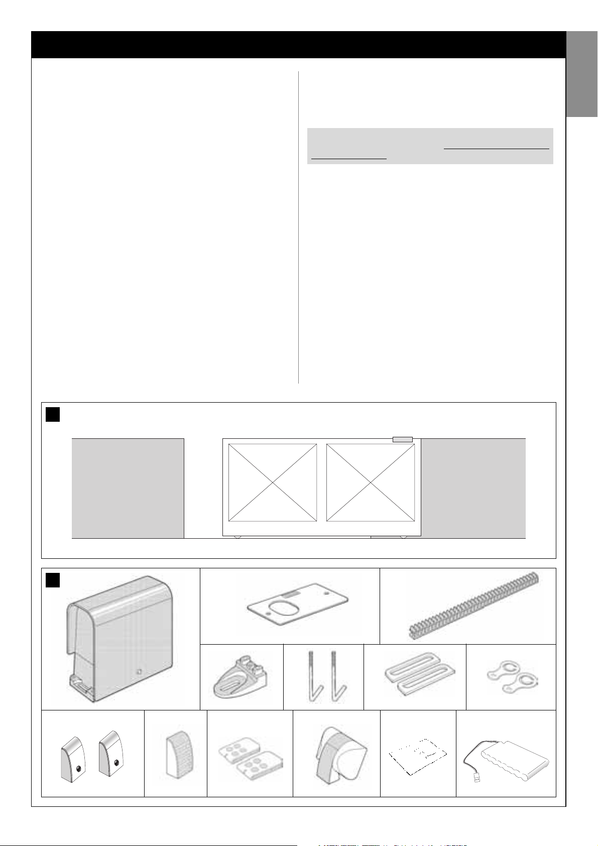
fig. 2 illustrates all components used to set up a complete system, such
as that shown in fig. 5.
List of components:
[a] - electromechanical gearmotor
[b] - foundation plate
[c] - rack
[d] - rack fixing brackets
[e] - anchor bolts
[f] - reinforcement plates
[g] - keys for manual release of gearmotor
[h] - pair of photocells mod. MP (wall-mounted)
[i] - control keypad mod. MK (wall-mounted)
[l] - portable transmitter mod. MT4
[m]- flashing light mod. MF
[n] - metal hardware (screws, washers, etc.)
[o] - buffer battery mod. MB
WARNING!
Some components shown in fig. 2 are optional and may not be
supplied in the pack.
KNOWLEDGE OF THE PRODUCT AND PREPARATION FOR INSTALLATION
1
a b
i m n oh
l
2
c
ef gd
6 – English
English
4
A
A
B
B
3
264 mm
78 mm
288 mm 176 mm
STEP 3
PRELIMINARY INSTALLATION WORK
Before proceeding with installation, check the condition of the product
components, suitability of the selected model and conditions of the
intended installation environment.
IMPORTANT – The gearmotor cannot be used to power a manual
gate that does not have a fully efficient and safe mechanical structure. Neither can it solve defects caused by poor installation or insufficient maintenance of the door itself.
3.1 – CHECKING SUITABILITY OF THE ENVIRONMENT
AND THE GATE TO BE AUTOMATED
• Ensure that the mechanical structure of the gate complies with current
national standards and that it is suitable for automation. (If present, refer
to the information specified on the gate dataplate).
• Move the gate leaf manually to open and close, checking that move-
ment has the same degree of friction throughout all points of travel (no
increase in friction must occur).
• Manually move the leafs to any position and leave stationary, ensuring
that they do not move from this position.
• Ensure that the space around the gearmotor enables safe and easy
manual gate release. (see chapter “Manually releasing or locking the
gearmotor” in the “Operation manual”).
• Ensure that the selected surfaces for installation of the various devices
are solid and guarantee a stable fixture.
• Ensure that all devices to be installed are in a sheltered location and pro-
tected against the risk of accidental impact.
• Ensure that the selected surfaces for fixing the photocells are flat and
enable correct alignment between photocells.
3.2 – CHECKING PRODUCT APPLICATION LIMITS
To ascertain suitability of the product with respect to the specific features
of the gate and area to be automated, the following checks should be performed as well as a check for compliance of the technical data in this
paragraph and the chapter “Product technical specifications”.
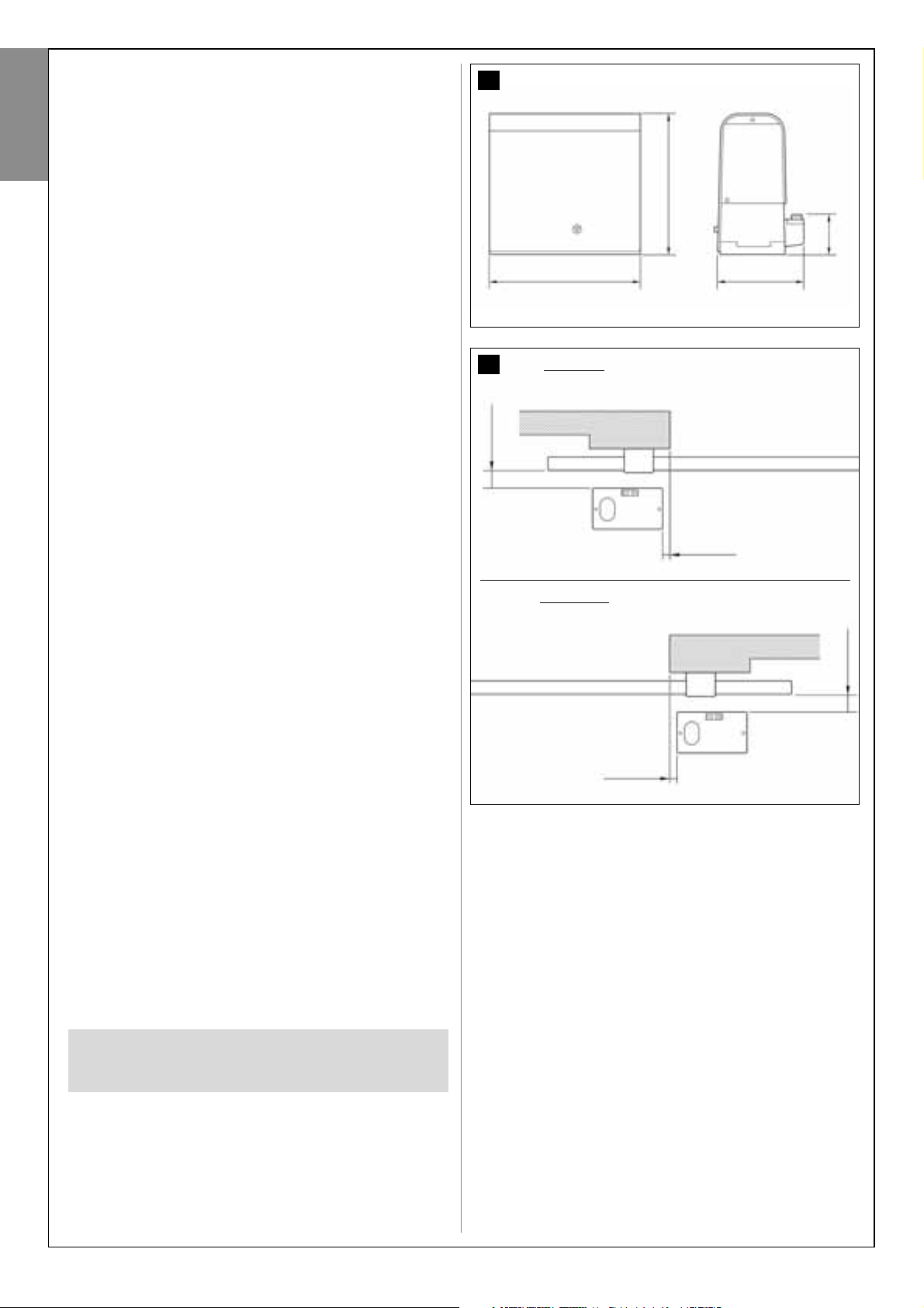
IMPORTANT – For the checks below, refer also to fig. 3 and 4:
– Fig. 3: indicates the overall dimensions of the gearmotor.
– Fig. 4: indicates values A and B, i.e. the minimum and maximum meas-
urements to observe when locating the position for the foundation plate.
Note – These measurements also serve as a reference to calculate the
space occupied by the foundation pit for routing the electrical cable ducting.
• Ensure that the dimensions and weight of the gate are within the follow-
ing limits of use.
- maximum length 5 m (
*
);
- maximum weight 300 kg.
(
*
) Note – The e rack supplied with this product is suitable for automation
of a gate with leafs of a maximum length of 4 m. If necessary, this may be
extended to a maximum length of 5 m using rack mod. MR1 (2 sections of
50 cm).
• Ensure that the dimensions of the selected area for mounting the gear-
motor is compatible with the overall dimensions.
• On the gate leaf, ensure that the surface for mounting the rack is suit-
able and solid.
CAUTION! – If the results of these checks do not conform to
specifications, this model cannot be used for automation of
your gate.
30 mm
30 mm
40 mm
40 mm
Left-hand
positioning of the gearmotor
Right-hand
positioning of the gearmotor

English – 7
English
CAUTION! - If forced to install the gearmotor on the left-hand side of
the gate, refer to the instructions in STEP 6.1.
4.1.4 – Establishing the device connection layout
The product envisages a “Bus” type connection between all system
devices, using a single cable with two electrical wires. In this type of connection, data communication between devices is via cable, using the specific protocol named “Bus-Moovo”.
CAUTION! – on the Bus system, only devices compatible with this protocol may be installed in the system.
On a “Bus” network, devices can be connected using various connection
configurations, and in each one, each device becomes a node of this network. The possible connection layouts are the following:
– “star”: In this configuration, each device is autonomous as it is connected directly to the two Bus terminals on the control unit.
– “chain”: In this configuration one device is connected to another and
the latter to another and so on, like links of a chain. Therefore only the first
device in the chain is connected to the two Bus terminals on the control
unit.
– “mixed”: this configuration is a combination of the two configurations
described above.
To select the most suitable connection configuration for the connection of
all system devices, refer to the example shown in fig. 7 / fig. 17. In gener-
al, it is recommended to connect the flashing light as the first device connected to the control unit.
STEP 4
4.1 – PRELIMINARY SET-UP WORK
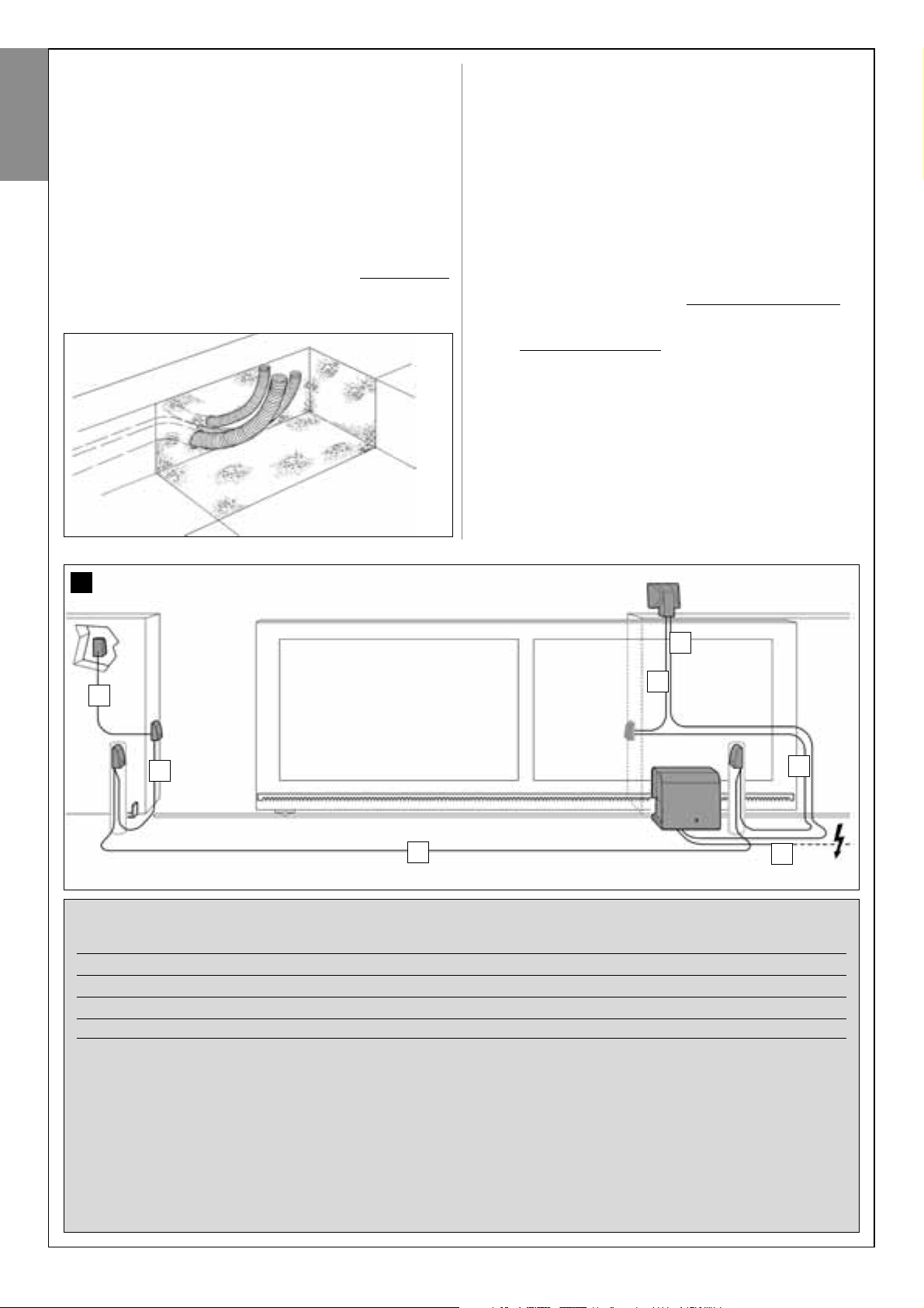
4.1.1 – Typical reference system
Fig. 5, shows an example of an automation system set up with Moovo
components. These parts are positioned according to a typical standard
layout. The following components are used:
a - Electromechanical gearmotor
b - Rack
c - Pair of photocells (wall-mounted)
d - Flashing light
e - Control keypad (wall-mounted)
f - Pair of photocells (on posts)
4.1.2 – Establishing positions of components
With reference to fig. 5, locate the approximate position for installation of
each component envisaged in the system. In particular, to establish the
position of the flashing light, refer also to fig. 20.
Warning – The “fixed” control devices must be visible from the gate but
positioned far from moving parts.
4.1.3 – Establishing the positions of the gearmotor
The gearmotor is factory set to be installed on the right-hand side of the
gate.
5
cc
d
e
f f
b
a
6
8 – English
English
TABLE 1 – Technical specifications of electric cables (see also paragraph 4.2)
Connection Cable type Maximum admissible len
A - FLASHING LIGHT cable Cable 2 x 1.0 mm
2
10 m (note 2)
B - POWER SUPPLY cable Cable 3 x 1.5 mm2(note 1) 30 m
D - BUS cable Cable 2 x 0.5 mm
2
20 m (note 3)
Note – The cables required for the set-up of the system (not included in the pack) may vary according to the quantity and type of
components envisaged for the system.
Note 1 – If the power cable supplied is not long enough, replace with a cable of this type. This task must be performed by skilled
and qualified personnel: Refer to the section “Tasks reserved for qualified technicians”.
Note 2 – If a greater length is required use a cable with diameter 2 x 1.5 mm
2
.
Note 3 – If a greater length is required use a cable with diameter 2 x 1.0 mm
2
.
CAUTION! – The cables used must be suited to the installation environment; for example a cable type H07RN-F for outdoor environments is recommended.
4.1.5 – Checking the tools required for work
Before starting installation, ensure that there is all equipment and materials required for the work concerned (see example in fig. 6); also ensure
that all items are in good condition and comply with local safety standards.
4.1.6 – Preliminary set-up work
Dig the routes for the ducting used for electrical cables, or alternatively
external ducting can be laid, after which the pipelines can be embedded
in concrete and other preparation work for the installation can be completed to finalise the site ready for subsequent installation operations.
In particular, for digging the pit for anchoring the gearmotor to the
ground, proceed as follows:
01. Dig the foundation pit in the gearmotor fixture point: refer to STEP
3.2.
Note – The dimensions of the pit must be the same or greater than
those of the foundation plate.
02. Lay the ducting used for electrical cables as shown in the figure
below.
CAUTION! – In general, position the ends of the ducting used for
electrical cables in the vicinity of the points envisaged for fixture of
the various components.
Note: The ducting serves to protect electrical cables and prevent accidental damage in the event of impact.
4.2 – PREPARING THE ELECTRICAL CABLES
When preparing the electrical cables required for your system, please
refer to fig. 7 and “Table 1 – Technical characteristics of the electric
cables”. In addition to this, you should always remember the following:
– In the “star” configuration, NONE of the individual cables linking up
any of the devices to the Control Unit may exceed 20 m in length
.
– In the “chain” configuration”, the sum of the lengths of each cable
used to connect one device to the other and, last of all, to the Control Unit MUST NOT exceed 20 m
.
– If connecting other devices between the Control Unit and the flashing lamp, use the same cable for these devices as was used for the
flashing lamp.
– All operations to lay the electric cables and connect them to the
various devices must be carried out during installation of the components.
7
A
B
C
C
C
C
C
English – 9
English
STEP 5
INSTALLING THE AUTOMATION COMPONENTS
WARNINGS
• Incorrect installation may cause serious physical injury to those
working on or using the system.
• Before starting automation assembly, make the preliminary checks
as described in STEP 3.
The following assembly phases illustrate the “physical” illustration of the
gearmotor.
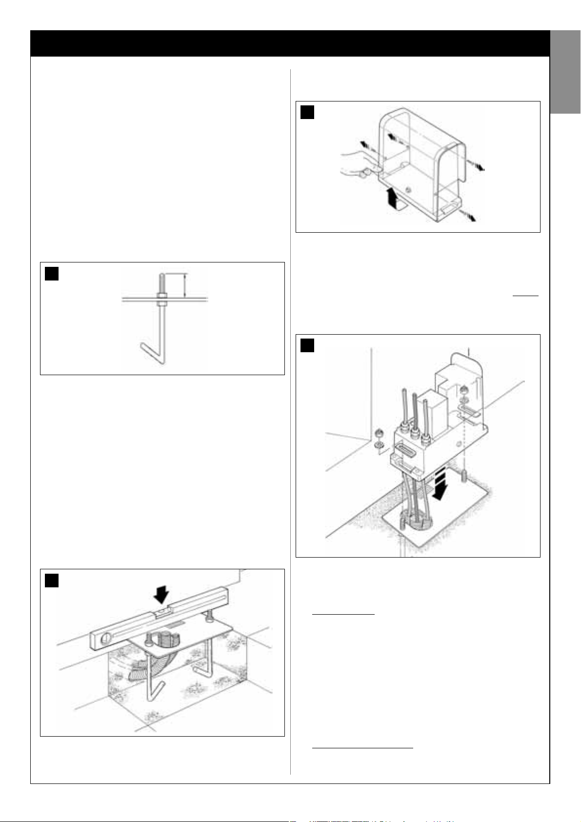
01. After digging the pit for fixture of the gearmotor (see STEP 4.1.7),
secure the anchor bolts to the plate as follows (fig. 8):
a) Tighten a standard nut (NOT locknut) fully down on each anchor
bolt.
b) Insert the anchor bolts so that the threaded section protrudes by
30 mm from the side of the plate bearing the pinion image.
c) Then temporarily tighten a standard nut (NOT locknut) onto the
ends of the anchor bolts. Note – In the next steps, the two upper
nuts will be removed and replaced with two locknuts.
02. Cast concrete into the pit, filling it to the edge and ensuring that the
ducting tube for electric cables come out of the surface.
03. While the concrete is still liquid, carefully place the foundation plate
on top, immersing the anchor bolts in the mix: shake the plate to
ensure that all air escapes from underneath and no bubbles form.
Take care to observe the following warnings (fig. 9):
– the side of the plate bearing the image of the pinion must be facing
the gate (see fig. 4);
– the ducting tube for routing the electric cables must pass through
the relative hole in the plate;
– observe the distances specified in fig. 4 to correctly position the
plate with respect to the gate leaf and wall.
– ensure that the plate is parallel to the gate and perfectly level (use a
spirit level).
04. When the concrete is solid (after a few days), loosen and remove the
upper nuts of the plate, which are no longer required.
05. Remove the gearmotor cover using a screwdriver to loosen the 4 lat-
eral screws (fig. 10). Note – Leave the gearmotor without the cover
until the installation and programming phases have been completed
06. Fig. 11:
a) Pass the electric cables through the relative holes and cable
clamps.
b) Gently place the gearmotor on the protruding section of the
anchor bolts so that they are inserted in the lateral holes of the gearmotor. Lock the assembly with the serrated washer and locknut
.
Note – Do not tighten the nuts fully down, as the gearmotor must
subsequently be moved forwards and backwards during rack
assembly.
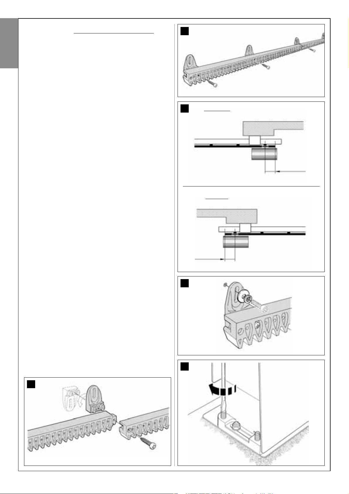
07. Assemble and secure the rack:
To facilitate this operation, the rack assembly should be put together
separately, including brackets, to then be mounted onto the gate leaf.
Assemble the rack
:
a) - establish the total length of the rack, which should be the same
length as the gate leaf. Then calculate the number of parts required
(sections of 50 cm) and if necessary cut one section to reach the
total required length.
b) - using a rubber mallet, join the two sections of the rack and insert
a fixing bracket in the joining point. Then secure the bracket by
means of a screw (fig. 12).
– To improve fixture of the rack to the gate leaf, fix a bracket also at
the centre of each section.
c) - assemble the other parts of the rack (fig. 13) proceeding as
described in point “b”. Lastly, fit a fixing bracket on each end of the
rack: this must be positioned between the 6th and 8th tooth of the
rack, starting from the end.
Fixing the rack to the gate leaf
:
d) - close the gate leaf completely.
INSTALLATION: COMPONENT ASSEMBLY AND CONNECTIONS
8
9
10
11
30 mm
10 – English
English
e) - position one end of the rack above the gearmotor pinion, taking
care to align the first fixing bracket with the centre of the pinion (fig. 14).
f) - using a spirit level, level the first section of the rack in the pinion
area and temporarily secure to the gate leaf by means of adhesive
tape.
Then repeat the same operations on the next section and so on
through the entire length of the rack, taking care to position each
section horizontally and perfectly aligned with the end placed on the
pinion.
g) - Tighten the fixing brackets fully down on the gate leaf as follows
(fig. 15): first secure the two brackets in the vicinity of the gear-
motor by means of screws and washers (with the gate completely closed). Then move the gate to bring the next bracket in
alignment with the pinion and secure it to the leaf.
Repeat the same operation for the next bracket and so on until all
brackets on the rack are secured.
Note – The screws required to fix the rack on the gate leaf are not
included in the pack as their type depends on the material and thickness of the leaf on which they are inserted.
h) - before securing the last section of the rack, completely open the
gate and check that the bracket on the end is aligned with the centre
of the pinion. If this is not so, move the bracket to this position and, if
necessary, use a hacksaw to cut off the excess section of the rack,
leaving a free section of approx. 5 cm. IMPORTANT - the rack must
not protrude from the gate leaf.
Caution – At the end of this work, check that the rack is perfectly level; the slots on the brackets enable corrections of small
differences in alignment during fixture.
08. Then secure the gearmotor onto the foundation plate, tightening the
two locknuts fully down: the pinion must be perfectly aligned with the
rack; if necessary slide the gearmotor forwards or backwards to
adjust.
09. Release the gearmotor by means of the special release key (see
chapter “Manually releasing or locking the gearmotor” in the
“Operation manual”) and move the gate leaf to mid-travel.
10. Make a number of complete manual gate opening and closing
manoeuvres to enable self-adjustment of the mechanical limit
switches. Important – During this manoeuvre, ensure that the rack
slides in alignment with the pinion.
11. Then move the gate leaf to mid-travel and lock the gearmotor
by means of the special key (see chapter “Manually releasing or
locking the gearmotor” in the “Operation manual”).
Note – The 4 stud bolts supplied in the pack must be used exclusively to
adjust the gearmotor height, when deciding to assembly the rack before
the gearmotor (fig. 16).
15
12
13
16
14
80 mm
Right-hand
positioning of the gearmotor
“Closing” position
C
80 mm
Left-hand
positioning of the gearmotor
“Closing” position
C
English – 11
English
17
CONNECTION LAYOUT
OF DEVICES WITH “BUS” SYSTEM
STEP 6
INSTALLATION AND CONNECTIONS OF SYSTEM DEVICES
Install and connect the system devices with reference to the STEPS below
and the example in fig. 17.
CAUTION! – Incorrect connections can cause faults or hazards;
therefore ensure that the specified connections are strictly
observed.
Flashing light
Pair of photocellsKeypad
12 – English
English
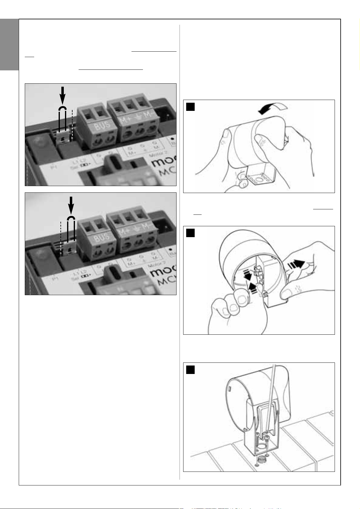
6.1 – SELECTION OF THE GEARMOTOR POSITION WITH
RESPECT TO THE GATE, ON THE CONTROL UNIT
The gearmotor is factory set to be installed on the right-hand side of the
gate: this setting is made by the position of the electric jumper “Sel” on
the control unit as shown in fig. A.
Otherwise, if installing the gearmotor on the left-hand leaf, move the electric jumper “Sel” to the position shown in fig. B.
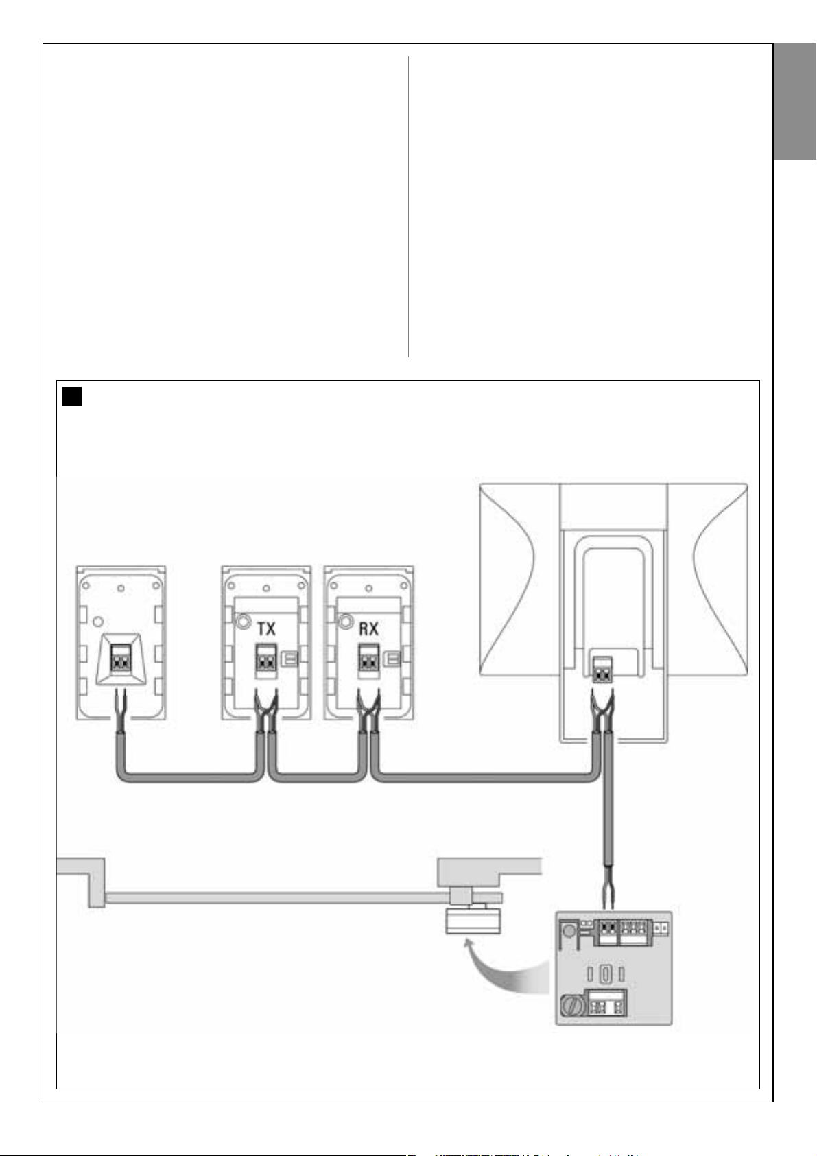
6.2 – INSTALLING AND CONNECTING
FLASHING LIGHT mod. MF
This flashing device indicates execution of each manoeuvre. It is also connected to the diagnostics system of the control unit and in the event of
malfunctions signals the type of problem by means of a pre-set sequence
of flashes (see paragraph “What to do if…”).
To install and connect the flashing light proceed as follows:
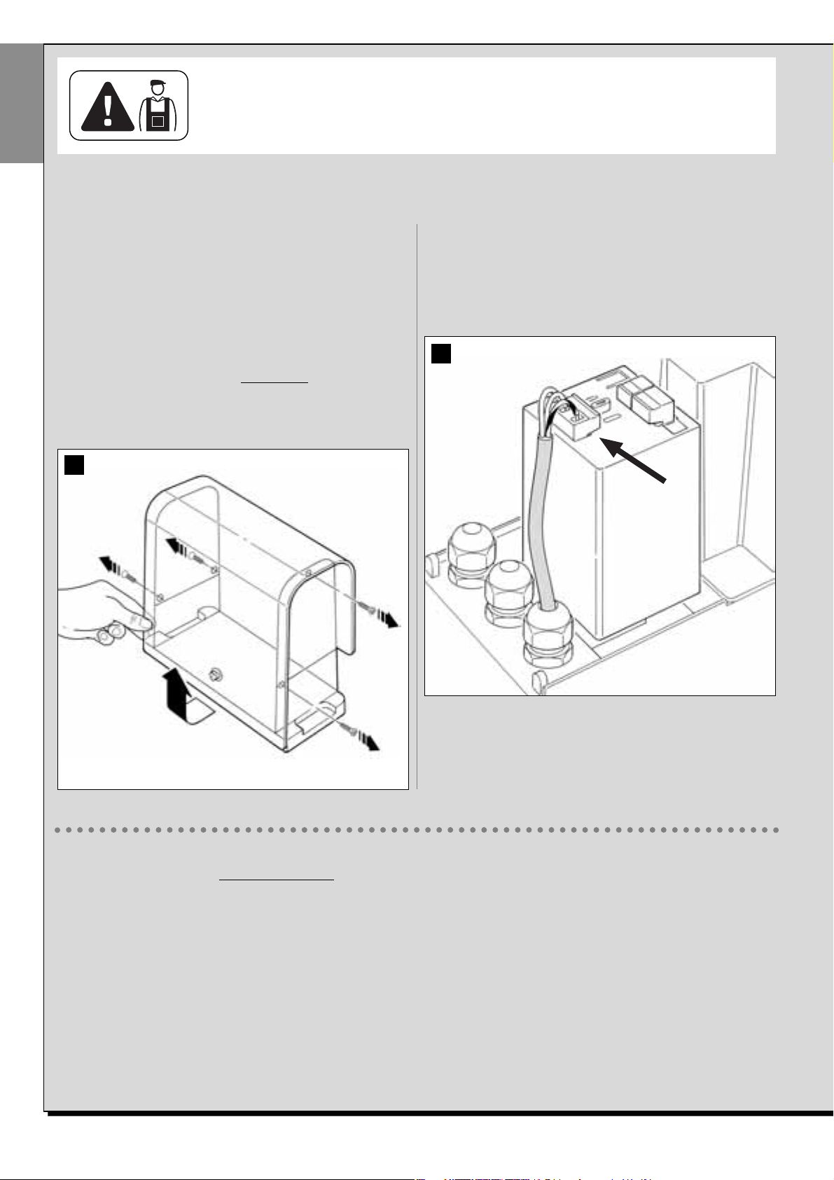
01. Fig. 17:
Extract one of the two transparent covers, turning it anti-clockwise
and set aside.
02. Fig. 18:
Use two fingers and at the same time press the two tabs at the bottom and use the other hand to remove the external cap of the flashing light.
03. Fig. 19:
Drill the marked sections on the base of the flashing light for fixture of
the screws and routing of the cables.
17
18
19
fig. A
fig. B

English – 13
English
04. Fig. 20:
CAUTION! - Do not mount the product in positions other than
those specified.
05. Fix the body of the flashing light to the wall with the relative screws,
routing the cables through the prepared hole.
06. Fig. 21:
a) Connect the wires of the two cables and secure on the terminal
board
b) Lock the cable by means of the relative cable clamp.
07. Fig. 22:
Insert the cap of the flashing unit in its seat until the tabs click in
place.
21
20
22
08. Fig. 23:
Refit the transparent cover in its seat and turn clockwise, taking care
that the serrated section engages with those on the flashing light
body.
09. Fig. 24:
a) On the gearmotor control unit, remove the BUS connection termi-
nal board from its seat to enable loosening of the 2 terminal screws.
b) Proceed with connection of the cable wires, observing the symbols on the terminal board and refit the latter in its seat.
c) Then tighten the cable clamp to secure the cable to the gearmotor.
23
24
14 – English
English
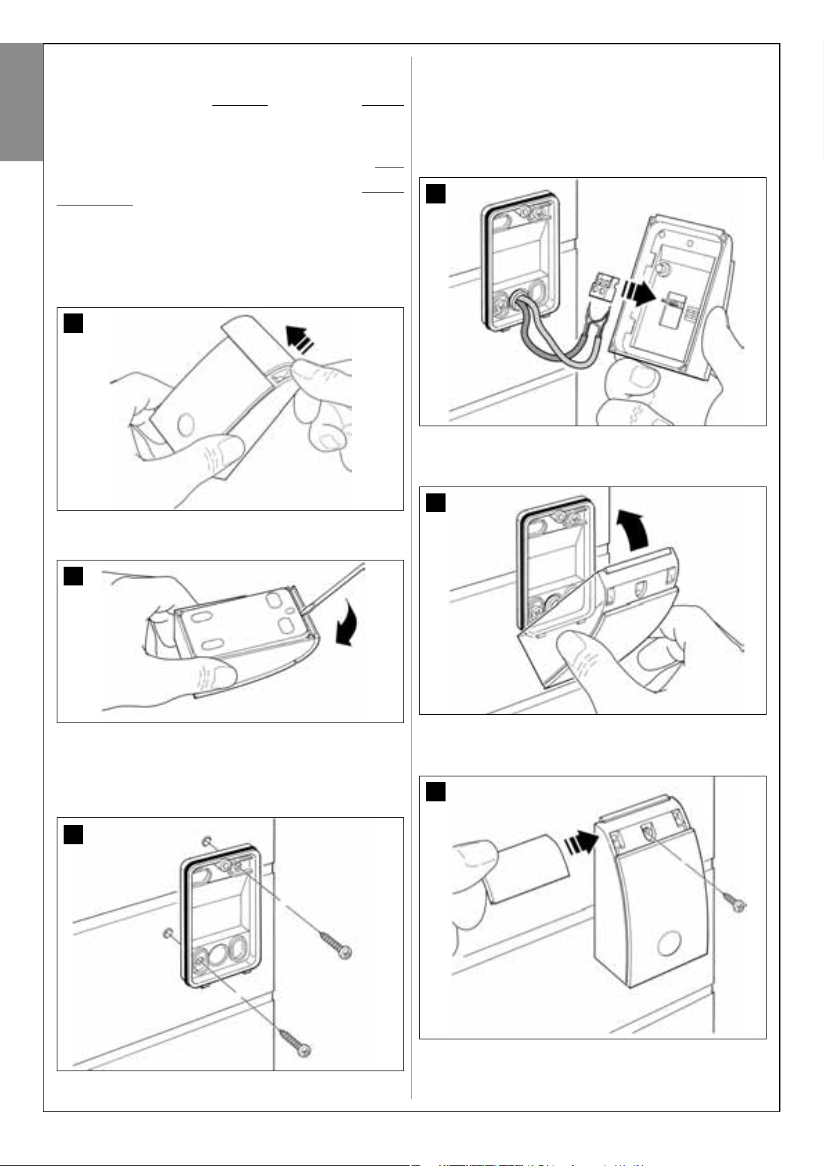
6.3 – INSTALLING AND CONNECTING
PHOTOCELLS mod. MP
A pair of photocells comprises a transmitting element (TX) and a receiving
element (RX). The photocells TX and RX are marked by a label inside the
cover.
Each photocell must be positioned on each side of transit and be facing
each other.
The system can be equipped with up to 6 pairs of photocells for safety
(enabling detection of obstacles present on the trajectory line between the
photocells) and a pair of photocells used to command an Opening
manoeuvre only (to install additional photocells, refer to section “Select-
ing operating modes of photocell pairs”).
To install and connect a pair of photocells proceed as follows:
01. Fig. 25:
Remove the screw cover cap by pushing down one side as shown in
the figure.
02. Fig. 26:
Using a screwdriver, open and detach the base of the photocell.
03. Fig. 27:
a) Drill a hole on the pre-cut section on the base for routing the con-
nection cables.
b) Fix the photocell base to the wall with the relative screws, routing
the cables through the prepared hole.
04. Fig. 28:
a) Connect the wires of the two cables and secure on the terminal
board.
b) Insert the terminal board in the male connector at the rear of the
photocell.
IMPORTANT! – Before closing the photocell, the photocell operating
mode must be selected by means of the relative jumper (refer to sec-
tion “Selecting operating modes of photocell pairs”).
05. Fig. 29:
Refit the cover, ensuring that the serrated section engages with that
of the photocell base.
06. Fig. 30:
Fix the photocell cover to the base by means of the screw supplied.
Lastly refit the screw cover cap as shown in the figure.
25
26
27
29
30
28
English – 15
English
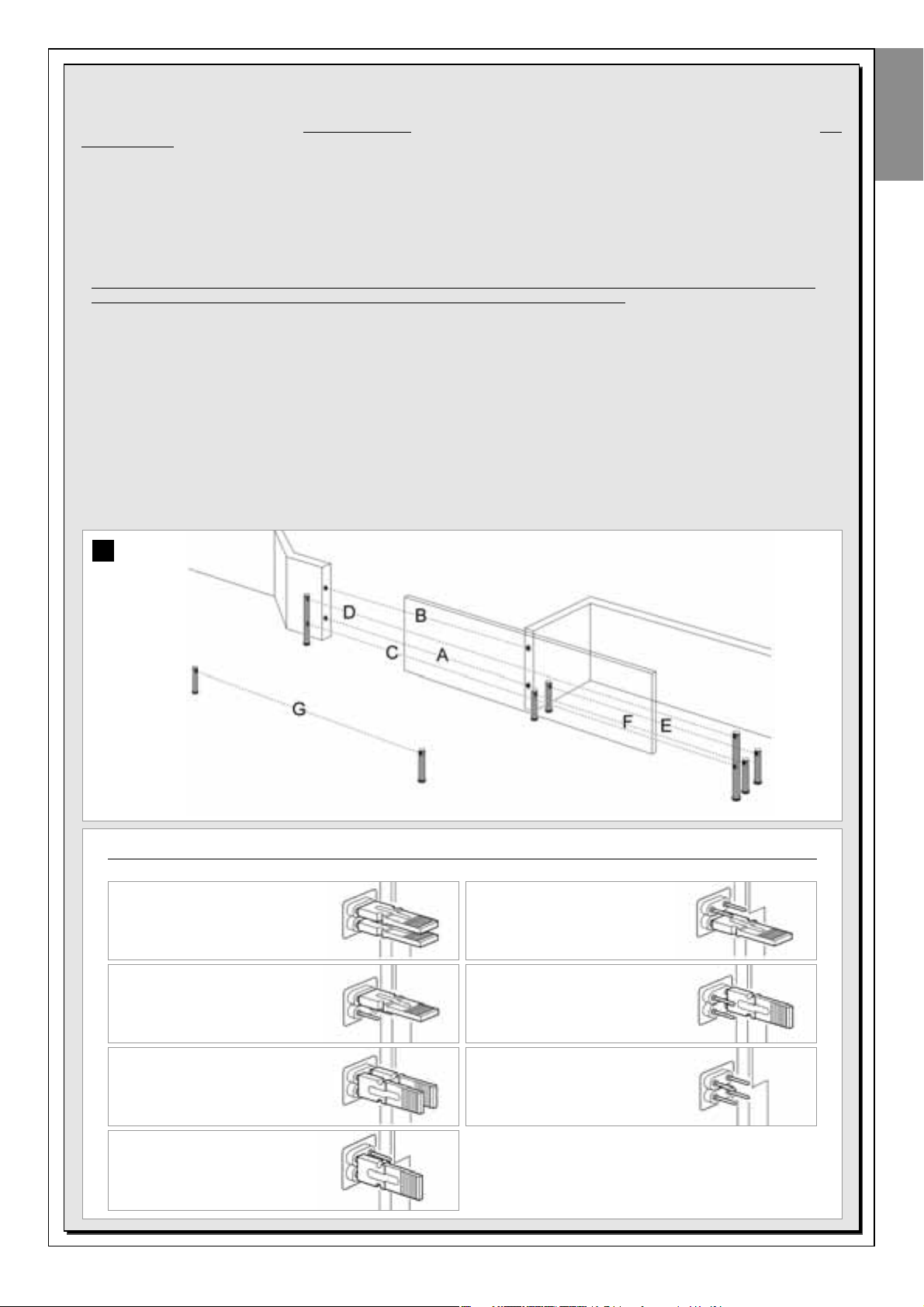
Additional pairs of photocells can be installed at any time on a system for sliding gates.
Up to a maximum of 6 pairs of photocells with safety functions can be added (as shown in the example A-B-C-D-E-F in fig. 31) and 1 pair with
a control function (as shown in the example G in fig. 31) which performs an Opening manoeuvre only.
For the correct location of these pairs of photocells, refer to fig. 31.
In order for the control unit to recognise each pair of photocells and the specifically assigned function, the devices must be assigned with
addresses by the insertion of one or two electric jumpers (Table 2) or no jumper at all (Table 2). In this way when the control unit receives the
input from the photocells it will activate the motor for the corresponding manoeuvre.
The address assignment procedure is performed both on the TX and RX photocell as follows:
For photocells “A-B-C-D-E-F”
Take care to observe the following warnings:
• the electric jumpers must be positioned on the two elements making up the pair of photocells (TX and RX) in the same position
;
• the same configuration used on one pair of photocells must NOT be used on other photocells.
To program these pairs of photocells (if fitted on the system) proceed as follows:
01. Open the cover of the photocell.
02. In fig. 31 locate the position in which the specific photocells are installed.
03. In Table 2 select the required configuration and insert electric jumpers in the two photocells.
For photocells “G”
Take care to observe the following warnings:
• These photocells have a different function from the other (controlling the automation), and therefore must be positioned at a specific distance
to avoid possible interference.
• These photocells remain powered also when the automation is on standby and in the event of a power failure, if the buffer battery is fitted, this
will reduce the standard lifetime (see STEP 6.5).
To program these pairs of photocells (if fitted on the system) no electric jumper must be inserted (see Table 2).
SELECTING THE PHOTOCELL PAIR OPERATING MODE
TABLE 2
Pair of photocells Electric jumpers
A Photocells h = 50 cm
(these are activated when
the gate is in the Closing phase)
B Photocells h = 100 cm
(these are activated when
the gate is in the Closing phase)
C Photocells h = 50 cm
(these are activated when
the gate is in the Opening
or Closing phase)
D Photocells h = 100 cm
(these are activated when
the gate is in the Opening
or Closing phase)
Pair of photocells Electric jumpers
E Photocells on right
(these are activated when
the gate is in the Opening phase)
F Photocells on left
(these are activated when
the gate is in the Opening phase)
G Gate opening
only command
31

16 – English
English
6.4 – INSTALLING AND CONNECTING
KEYPAD mod. MK
The control keypad is a wall-mounted device used for control of the
automation via a Bus connection. Up to 4 keypads can be connected in a
single system and the device can be programmed to operate in two
modes: Traditional mode (each key performs a specifically assigned function– factory set) and safety mode (to activate a manoeuvre, a secret key
sequence must be entered, as set by the user).
The keypad is backlit for poorly lit conditions.
To install and connect the keypad proceed as follows:
01. Fig. 32:
Remove the keypad cover by pushing down one side as shown in
the figure.
02. Fig. 33:
Using a screwdriver, open and detach the base of the keypad.
03. Fig. 34:
a) Drill a hole on the pre-cut section on the base for routing the con-
nection cables.
b) Fix the keypad base to the wall with the relative screws, routing
the cables through the prepared hole.
04. Fig. 35:
a) Connect the cable wires to the respective terminals.
b) Insert the cable connector in the male connector at the rear of the
keypad.
05. Fig. 36:
Refit the cover, ensuring that the serrated section engages with that
of the keypad base.
06. Fig. 37:
Fix the keypad cover to the base by means of the screw supplied.
Lastly refit the screw cover cap as shown in the figure.
Note – To program the keypads in the system, refer to STEP 9.3.
34
37
36
35
33
32
English – 17
English
02. Fig. 39:
Insert the battery connector in the male connector on the control
unit.
WARNINGS
To guarantee optimal lifetime of the buffer battery, the following warnings should be
observed:
• When the buffer battery is completely discharged, around 24 hours are required to
completely recharge.
• The buffer battery is an emergency device: therefore in the event of a power failure,
only moderate use is advisable. Excessive and continuous use can lead to overheating of the elements, which over time may reduce the normal lifetime of the battery.
• In the event of a power failure, never leave the automation powered exclusively by
the buffer battery for periods longer than a day: The elements may overheat excessively and impair lifetime of the battery.
Therefore, if absent from the installation site of the automation for prolonged periods, it is recommended to detach the buffer battery terminal connected to the
control unit.
• In the event of prolonged periods of disuse, the optional battery should be
removed and stored in a dry location to avoid the risk of leaks of harmful substances.
–––––––––––––––––––
Battery disposal
CAUTION! – Even if discharged, the batteries can contain pollutant substances and therefore must NEVER be disposed of in common waste collection points. Dispose of according to separate waste collection methods
as envisaged by current local standards.
6.5 – INSTALLING BUFFER BATTERY mod. MB
The buffer batteries are self-charging with a voltage of 12V and power of
2100mAh. These are particularly useful in the event of a sudden power
failure. The gearmotor with control unit enables installation of 1 battery.
Depending on the type and weight of the gate, when charged, the battery
guarantees an autonomy of approx. 6 - 7 consecutive movement cycles
(1 cycle = opening - closing).
To install the buffer battery proceed as follows:
01. Fig. 38:
Inside the gearmotor, insert the battery in the space alongside the
control unit.
CAUTION! – The point below (02 – electrical
connection of the buffer battery to the control
unit ) must only be performed after completing
all installation and programming phases, as the
battery is an emergency power source.
CAUTION! – For safety reasons, the buffer battery must only be installed after completing
installation and programming, and after checking correct operation of the system.
38
39
18 – English
English
POWER SUPPLY CONNECTION
INITIAL START-UP AND ELECTRICAL CONNECTION CHECK
STEP 8
CAUTION! – The following operations described in this manual will
be performed on live electrical circuits and therefore manoeuvres
may be hazardous! Therefore proceed with care.
After powering up the control unit (fig. 50), the red Led and green Led
(fig. 41) emit a series of flashes.
At the end of this phase, the red led starts flashing at regular intervals.
This confirms correct operation of the control unit.
CAUTION! – If the red led does not flash as described above, disconnect the Control unit from the power supply and carefully check
all connections (refer also to the paragraph “What to do if...”).
41
“L2” green led“L1” red led
Key “P1”
STEP 7
WARNINGS!
– The PVC power supply cable supplied serves exclusively for
automation operation and programming tests.
– The final connection
of the automation to the electrical
mains and replacement of the cable supplied, must be performed by a qualified electrician, in compliance with local
standards and the instructions in the section “Tasks reserved
for qualified technicians”.
– The replacement cable must be suitable for outdoors, such
as type H07RN-F. The cable must also be protected against
impact by means of an insulated protection duct.
To perform the automation operation and programming tests, insert the
power plug of the control unit (supplied) in a mains socket (fig. 40). If the
socket is far from the automation, use a suitable extension lead.
40
English – 19
English
WARNINGS for programming:
• Always read the procedure first and then perform the operations in the
correct sequence.
• In this manual the transmitter keys are identified by means of numbers.
To check the correspondence of numbers and the transmitter keys see
fig. 42.
STEP 9
9.1 – MEMORISING THE DEVICES CONNECTED BY
MEANS OF “BUS” CABLE AND THE LEAF “CLOSING”
AND “OPENING” LIMIT POSITIONS
After ensuring correct operation of the control unit, it must be programmed as described in the sequence below:
Note – During this procedure, the user can exit the process at any time
(without saving the operations performed) by pressing “P1” once
on the
control unit (fig. 41). In particular, from point 07 onwards, the user can
also exit the procedure by activation of a safety device (photocell or other...).
01. (on the gate)
Release the gearmotor by means of the special release key (see
chapter “Manually releasing or locking the gearmotor” in the section TECHNICAL DOCUMENTATION) and manually move the gate
leaf to mid-travel. Then lock the gearmotor again.
02. (on the control unit)
Press and hold the key “P1” for at least 5 seconds; the green and red
Leds illuminate. Then release the key when the green led turns off (the
red led remains lit through to the end of the procedure) and proceed
as follows:
03. (on safety Photocells)
Note – The time available for this check is unlimited.
Check correct operation of these types of photocells, ensuring that
the relative Led flashes slowly. Otherwise if it is lit or off, correct alignment between the photocells attempting to obtain a flashing frequency that is slow as possible (the slower the flashing speed, the better
the photocell alignment).
• slow flashing light
= correct photocell alignment;
• light permanently lit
= incorrect alignment (revise photocell align-
ment);
• light off
= photocells installed incorrectly (check “Bus” connection of
photocells).
04. (on control Photocells)
Activate this type of photocell (if fitted on the system), interrupting the
beam once only. Successful learning is confirmed by the flashing light
(1 flash) and the keypad (1 beep), if fitted on the system.
05. (on the keypads)
Activate the keypads (if fitted on the system) by pressing any key on
each one as required.
Successful learning is confirmed by 2 beeps at short intervals, emitted
by the keypad and 1 flash of the flashing light, if fitted on the system.
06. (on the control unit)
Press and hold the key “P1” for at least 5 seconds; the green led illuminates and release the key when the green Led turns off.
07. (on the gate)
At this point the ate leaf moves independently to reach the Opening
limit position.
Note – If fine adjustments to the travel limit position are required, use
the adjustment screw inside the gearmotor as follows (fig. 43):
Locate the screw with the arrow corresponding to the direction in
which the leaf is moved, and adjust until the leaf reaches the required
limit position.
08. (on the control unit)
Press and hold the key “P1” for at least 5 seconds; the green led illuminates and release the key when the green Led turns off.
09. (on the gate)
At this point the gate leaf moves independently to reach the Closing
limit position.
Note – If fine adjustments to the travel limit position are required, use
the adjustment screw inside the gearmotor as follows (fig. 44):
Locate the screw with the arrow corresponding to the direction in
which the leaf is moved, and adjust until the leaf reaches the
requiredlimit position.
10. (on the control unit)
Press and hold the key “P1” for at least 5 seconds; the green led illu-
minates and release the key when the green Led turns off.
At this point the control unit independently starts 2 manoeuvres also
indicated by the flashing light:
1 - Leaf opening.
2 - Leaf closure.
At the end of the last manoeuvre, the red led turns off (= procedure
completed) and then resumes flashing at regular intervals.
If the results of these checks do not conform with specifications, stop
the procedure immediately by pressing P1 on the control unit once
.
Then repeat the entire procedure 9.1 and check correct operation of
the photocells, or modify settings of the “Leaf sensitivity to obsta-
cles” as described in Chapter 10 “Automation operation adjustment”
and if necessary check electrical connections.
PROGRAMMING THE AUTOMATION
42
T1
T3
T2
T4
43
44
20 – English
English
Memorising other devices connected by Bus cable at a later
date
If in future the user decides to install and memorise other devices connected to the control unit by means of the Bus, and procedure 9.1 has
been completed previously, the new devices can be memorised using
the same procedure, starting from point 01 through to point 06. On completion, press P1 once on the control unit to complete the memorisation
process.
9.2 – MEMORISATION OF TRANSMITTER mod. MT4
CAUTION! – Always read the procedure first and then perform the
operations in the correct sequence without allowing more than 10 seconds to pass between releasing one key and pressing the next.
To enable control of the automation with the transmitter, the keys must be
memorised in the control unit memory.
Memorisation enables the association of each key with the required command, selecting from the following:
1 = Step-Step: Corresponds to the sequence ... Open - Stop – Close -
Stop... The first command activates Opening; the next, with the leaf mov-
ing, activates Stop; the third activates Closure; the fourth with the leaf
moving activates Stop and so on...
2 = Step-Open: Corresponds to the sequence ... Open - Stop – Close
- Open... The first command activates Opening; the next, with the leaf
moving, activates Stop; the third activates Closure; the fourth with the
door moving activates Open and so on...
3 = Partial open: Corresponding to total opening of the leaf. This com-
mand is only activated if the leaf is in the lower position (1 m) with respect
to the Partial Open position; otherwise a Step-step command is activated.
4 = Apartment block open: This command is used for apartment
blocks and envisages programming of all apartment block transmitters
with a single “apartment block opening” key. This command operates as
follows:
• if the command is sent when the gate is completely closed, the Opening
manoeuvre is started.
• if the command is sent while an Opening manoeuvre is in progress, the
manoeuvre continues;
• if the command is sent while a Closing manoeuvre is in progress, the
manoeuvre is interrupted and an Opening manoeuvre is started;
• if the command is sent when the gate is completely open, the Closing
manoeuvre is started. Note – Automatic closure of the gate is also pos-
sible, by programming a pause time as required (see chapter 10).
A single procedure memorises a single key of the transmitter on this control unit. The control unit memory can memorise up to 150 keys.
For each key to be memorised, repeat the following procedure.
01. Select which transmitter key is to be memorised (for example: Key T3).
02. Decide on the command (from those listed below) to be associated
with the selected key (for example: Command “
2”).
03. Press “P1” (on the Control unit) the same number of times as the
selected command number (in the example “2”, i.e. twice) and check
that the green led emits the same number of quick flashes (repeated
at regular intervals).
04. (within 10 seconds) Press and hold the transmitter key to be memo-
rised for at least 5 seconds (in the example, key T3).
If the memorisation procedure is successful, the green led emits 3 long
flashes (= memorisation OK). Note – Before the 10 second interval elaps-
es, the key of a NEW transmitter with the same command
can be memorised (useful, for example, when several transmitters need to be memorised on the same control unit).
Otherwise wait until the green led turns off (= procedure completed) and
for the red led to resume flashing at regular intervals.
9.3 – PROGRAMMING KEYPAD mod. MK
The control keypad can be programmed for two alternative operating
modes:
- TRADITIONAL mode
(without the use of a personal password)
- SAFETY mode
(with use of a personal password)
After memorisation (see STEP 9.1) the keypad is set to “Traditional mode”
(factory setting) but this may be modified as described below.
“Traditional” operating mode”
In this mode the keys are independent and each commands a specific
action. The commands are:
Key “A” = Step-step command
Key “B” = “Partial open” command
Key “C” = Open Command
Key “D” = Close command
Key “OK” = Stop Command
“Safety” operating mode”
In this mode the keypad is enabled on entry of a password set by the user
(from 1 to 10 letters) followed by the key OK. This combination of keys
only sends the specific command that the user set during the mode programming phase.
Note – If the Step-Step command is programmed, after the command is
sent the user has 10 seconds in which to send a subsequent command,
by simply pressing “OK”. This eliminates the need to repeat password
entry.
“SAFETY” MODE PROGRAMMING
01. Press And hold keys “A” and “B” simultaneously for a few seconds,
until the keypad emits a sequence of beeps that indicate start-up of
programming.
02. Using the keys enter the “PUK code” (10-letter code printed on the
badge supplied with the keypad); and then press “OK”.
03. Using the keys enter the personal password (from 1 to 10-letters);
and then press “OK”.
The keypad emits a series of beeps.
04. From the list below, select the command to be programmed and on
the keypad press the key to be associated with the command followed by OK:
Step-Step command = key A
Partial open command = key B
Open command = key C
Close command = key D
Stop command = key OK
The keypad emits a series of beeps to indicate completion of programming.
Modifying the Personal Password
To modify you personal password, repeat the entire “Safety mode” procedure, changing the existing password at point 03.
“TRADITIONAL” MODE PROGRAMMING
To program this mode, perform only points 01 and 02 of the “Safety mode
pr
ogramming” procedure, and then “OK” twice.
English – 21
English
The control unit has a number of optional functions to enable the user to
add specific functionalities to the automation, thus personalising the product according to special needs.
10 – AUTOMATION OPERATION ADJUSTMENT
To personalise operation of the automation, a number of functions can be
enabled or disabled, also with the option for modifications to settings as
required. The functions are:
• AUTOMATIC LEAF CLOSURE
. When this function is enabled, at the
end of the Opening manoeuvre command by the user, the control unit
automatically closes the gate again after a set time interval.
• LEAF MOVEMENT SPEED
. This function enables entry of the required
speed of the automation implemented to move the gate leaf.
• AUTOMATION SENSITIVITY TO OBSTACLES
. During a manoeuvre, if
an obstacle accidentally stops gate leaf movement (a strong gust of wind,
a vehicle, person etc.) this function promptly detects the increase in motor
stress to contract the obstacle and activates immediate total inversion of
movement. If “automatic leaf closure” is set, the control unit re-attempts
the movement a second time and on the third time, after a brief inversion,
it stops the manoeuvre permanently.
• DECELERATION MODES
. This function enables selection of the deceleration start point during gate leaf travel both in the Closing and Opening
phases.
Note – This parameter is essential for guaranteeing a low impact force in
the event of impact with an obstacle in the final phase of a manoeuvre.
The values of these functions can be set according to personal requirements using the following procedure with a transmitter that has at least
one key already memorised on the control unit.
Note – During this procedure, each time a key is pressed the flashing light
emits one flash.
01. Press and hold the keys “T1” and “T2” simultaneously on the trans-
mitter for at least 5 seconds, after which release.
The two leds (green and red) on the Control unit flash to indicate entry
to function programming mode (the leds continue to flash throughout
the procedure).
02. Press and hold a transmitter key (already memorised on that of the
control unit) for at least 1 second (the green Led emits one flash).
03. Then select one of the four functions available and on the transmitter
press the key associated with the function for at least 1 second (the
green Led emits one flash):
• Automatic leaf closure = (press key “T1”)
• Leaf movement speed = (press key “T2”)
• Leaf sensitivity to obstacles = (press key “T3”)
• Leaf deceleration points = (press key “T4”)
04. Lastly, refer to Table 3, select the required value in correspondence
with the selected function and on the transmitter press the key associated with the selected value for at least 1 second (the green and
red Leds emit one confirmation flash).
Notes to Table 3:
– The Table states the values available for each of the 4 special functions
and the corresponding key to be pressed on the transmitter for selection
of the specific value.
– The factory settings are highlighted in grey.
(*) – The “High” parameter means that the gate can detect obstacles that
generate a low force
, such as a strong gust of wind.
– The “Low” parameter means that the gate can detect obstacles that
generate a high force
, such as a stationary car.
– In the event of a power failure, on restoral of power the first manoeuvre
command will be executed at low speed, regardless of the type of speed set.
11 – MEMORISING A NEW TRANSMITTER WITH
PROCEDURE IN THE VICINITY OF THE CONTROL
UNIT [with a transmitter already memorised]
A NEW transmitter can be memorised in the control unit memory without
acting directly on key P1 of the control unit, but by simply working within
its reception range. To use this procedure, an OLD transmitter, previously
memorised and operative, is required. This enables memorisation of the
same function of a specific key on the OLD transmitter on any key of the
NEW transmitter.
Warnings:
– The procedure must be performed within the reception range of
the receiver (maximum 10-20 m from receiver).
– The procedure memorises a single key of the new transmitter. To
memorise other keys, repeat the same procedure
01. On the NEW transmitter, press and hold the key to be memorised for
at least 5 seconds and then release.
02. On the OLD transmitter, slowly press the control key to be memo-
rised on the other transmitter 3 times.
03. On the NEW transmitter, press the same key pressed in point 01
once.
ADJUSTMENTS AND OTHER OPTIONAL FUNCTIONS
TABLE 3
AUTOMATIC LEAF CLOSURE
No closure —> (press key “T1”)
Closure after 15 seconds —> (press key “T2”)
Closure after 30 seconds —> (press key “T3”)
Closure after 60 seconds —> (press key “T4”)
LEAF MOVEMENT SPEED
Low —> (press key “T1”)
Medium low —> (press key “T2”)
Medium high —> (press key “T3”)
High —> (press key “T4”)
AUTOMATION SENSITIVITY TO OBSTACLES
High(*) —> (press key “T1”)
Medium high —> (press key “T2”)
Medium low —> (press key “T3”)
Low(*) —> (press key “T4”)
DECELERATION MODES
20 cm in Opening / 20 cm in Closing
low impact speed —> (press key “T1”)
20 cm in Opening / 70 cm in Closing
low impact speed —> (press key “T2”)
70 cm in Opening / 70 cm in Closing
low impact speed —> (press key “T3”)
70 cm in Opening / 70 cm in Closing
very low impact speed —> (press key “T4”)
22 – English
English
12 – DELETING DATA FROM THE CONTROL UNIT MEMORY
Data in the control unit memory can be deleted partially or totally as
required. To do this, the following procedures can be used, as required:
• Deletion of a command on a transmitter already memorised
• Deletion of other data memorised on the control unit
Deleting a command
on a transmitter already memorised
The following procedure enables deletion of a single command assigned
to a transmitter key from the control unit memory.
Note – During the procedure, the red and green leds remain permanently lit.
01. Press and hold the key “P1” on the Control unit for at least 10 seconds:
the green Led illuminates first, then the red led illuminates after 5 seconds and then both, to indicate that the Control unit has entered memory deletion mode (WARNING! do not release the key P1!
).
02. Without releasing key P1 press the transmitter key to be deleted: if
the control unit recognises this operation, the green led emits a short
flash, after which the P1 key and transmitter key can be released.
Deleting other
data memorised on the control unit
The following procedure enables deletion of various types of memorised
data from the control unit memory, as specified in Table 4.
Note – During the procedure, the red and green leds remain permanently lit.
01. Press and hold the key “P1” on the Control unit for at least 10 sec-
onds: the green Led illuminates first, then the red led illuminates after
5 seconds and then both, to indicate that the Control unit has
entered memory deletion mode. Then release the key.
02. With reference to Table 4, select the data to be deleted and press P1
the same number of times as the number of presses specified in
brackets (the green led emits one flash each time the P1 key is
pressed).
03. 5 seconds after the key “P1” is pressed for the last time, if deletion is
successful, both leds (red and green) flash quickly (= memory delet-
ed!).
Note – Before deletion, there is a margin time of 5 seconds, in which
the user has the option to change decision and exit the procedure
without deleting data by pressing key P1 five times.
IMPORTANT! – After deletion of the “Memory of
Closing and Opening
limit positions” and “TOTAL Memory”, the procedure 9.1 – “memorising
the devices connected by means of “bus” cable and the leaf “Closing” and “Opening” limit positions.
13 – AUTOMATION TESTING AND COMMISSIONING
After completing all programming phases, including adjustments, the
automation must undergo the testing and commissioning procedures as
specified in the section “Tasks reserved for qualified technicians”.
14 – INSTALLING AND CONNECTING A BUFFER BATTERY
After completing the testing and commissioning phases, it is possible to
install and connect a buffer battery mod. MB, if envisaged in the system.
For this operation refer to STEP 6.5.
TABLE 4
• Memory of Optional Function values (= 1 press)
• Memory of “Closing” and “Opening” limit positions (= 2 presses)
• Memory of Transmitters (= 3 presses)
• TOTAL memory (= 4 presses) Note – deletes the first three mem-
ories in one process

English – 23
English
WHAT TO DO IF... (Troubleshooting guide)
During normal operation, the control unit constantly monitors the automation processes and is designed to indicate any faults that arise, by means of a
pre-set sequence of flashes emitted by the flashing light and red led “L1” on the control unit (the diagnostics flashes always refer to the last action performed by the automation). For an explanation of the number of flashes and associated cause, refer to Table 5 below:
TABLE 5
Flashes
2 flashes - pause - 2 flashes
3 flashes - pause - 3 flashes
4 flashes - pause - 4 flashes
5 flashes - pause - 5 flashes
6 flashes - pause - 6 flashes
7 flashes - pause - 7 flashes
8 flashes - pause - 8 flashes
Problem
During the Opening or Closing manoeuvre the door
blocks or inverts the manoeuvre in progress.
• During the Opening or Closing manoeuvre the
door blocks suddenly and the control unit activates
a total
inversion of the manoeuvre in progress to
reach the limit switch.
Note – During this inversion, if the leaf detects a second obstacle, it inverts movement again, and if a
third obstacle is detected the gate blocks movement
without reaching the travel limit.
(The automation is factory-set not to exceed three
attempts).
During the Opening or Closing manoeuvre the gate
leaf blocks suddenly and the control unit activates a
Stop followed by a brief inversion of movement.
The automation does not respond to commands.
After a series of manoeuvres sent consecutively, the
automation is blocked.
The automation does not respond to commands.
The automation does not respond to commands.
Solution
This reaction is caused by the activation of a
specific pair of photocells in the system, on
detection of an obstacle. Therefore remove the
obstacle on the trajectory of these photocells.
The leaf is subject to increased friction due to a
sudden obstruction (a strong gust of wind, vehicle, person etc.). If adjustment to sensitivity is
required, refer to the Chapter “Adjustments and
other optional Functions”.
A safety device installed (other than photocells,
such as sensitive edges) has detected a sudden
obstacle.
Therefore remove the obstacle.
There is a system configuration error. Ensure correct insertion of the jumper “Sel” on the control
unit. Then repeat installation.
The maximum admissible number of consecutive manoeuvres has been exceeded, causing
excessive overheating. Wait for a few minutes to
enable the temperature to return below the maximum limit.
Error in internal electric circuits. Disconnect all
power circuits, wait a few seconds and then reconnect. Retry a command; if the automation
does not respond this may indicate a serious
fault with the electrical board of the control unit
or motor wiring. Check and make replacements
as necessary.
Error in “Bus” internal electric circuits. Check
operation of the connected devices one by one.
These may be short circuited or malfunctioning.
24 – English
English
To connect the new cable to the electrical mains:
ACAUTION! – When making this connection, the electrical mains power line must be equipped with short-circuit protection device (between the
automation and the mains).
The electrical mains line must also be equipped with a power disconnect device (with overvoltage category III, i.e. minimum gap between contacts of
3.5 mm) or an equivalent system such as socket with removable plug.
This device, when necessary, guarantees fast and safe disconnection of the power supply and therefore must be placed in a location visible from the
automation. If the power disconnect device is not in the vicinity of the automation and not visible from the latter, it must be fitted with a lockout facility
to prevent inadvertent or unauthorised connection.
Note – The disconnect devices are not supplied with the product.
CONNECTING THE AUTOMATION TO THE ELECTRICAL MAINS
WITH A CABLE OTHER THAN THE VERSION SUPPLIED
CAUTION! – Incorrect connections can cause faults or hazards;
therefore ensure that the specified connections in this paragraph are
strictly observed.
In the case of this product, the cable supplied may need to be replaced
with a protected electric line suited to the installation.
In this case, use a power cable with the dimensions 3 x 1,5 mm2, and
maximum length of 30 m. For greater lengths, use a cable with a larger
section: For example , 3 x 2,5 mm2, ensuring safety earthing in the vicinity
of the automation. Then proceed as follows.
To connect the new cable to the Control unit
:
01. Fig. A - Remove the gearmotor cover using a screwdriver to loosen
the 4 lateral screws.
02. Fig. B - Loosen the power cable clamp, loosen the screw of the ter-
minal board cover using a Phillips screwdriver and remove the existing cable. Then fix the new cable to the terminal board, observing the
relative symbols. Note – the terminal board can be removed from its
seat to facilitate wiring.
– Brown wire, to connect to “Phase”;
– Blue wire, to connect to “Neutral”;
– Yellow-green wire, to connect to “Earth”.
03. Then refit the terminal board cover and close the gearmotor with its
cover.
Tasks reserved for qualified technicians
CAUTION! – All operations in this section must be performed exclusively by skilled and qualified
personnel, in observance of the instructions in the manual, and current local legislation and safety standards in the place of installation.
A
B
English – 25
AUTOMATION TESTING
1 Ensure that all specifications in STEP 1 regarding safety have been
strictly observed.
2 Using the transmitter, perform gate opening and closing tests and
ensure that the leaf movement corresponds to specifications.
Test several times to assess smooth operation of the gate and check
for any defects in assembly or adjustment and any possible points of
friction.
3 Check operation of all system safety devices one at a time (photocells,
sensitive edges, etc.). Photocells
: Activate a single pair of photocells
during a manoeuvre (see Table 2 to identify which manoeuvre to per-
form) and check that the control unit stops the manoeuvre and activates a total inversion of the movement (the flashing light emits 2 flashes, twice). Sensitive edges: Activate the device during an Opening or
Closing manoeuvre and check that the control unit stops the manoeuvre and activates a brief inversion of the movement (the flashing light
emits 2 flashes, twice).
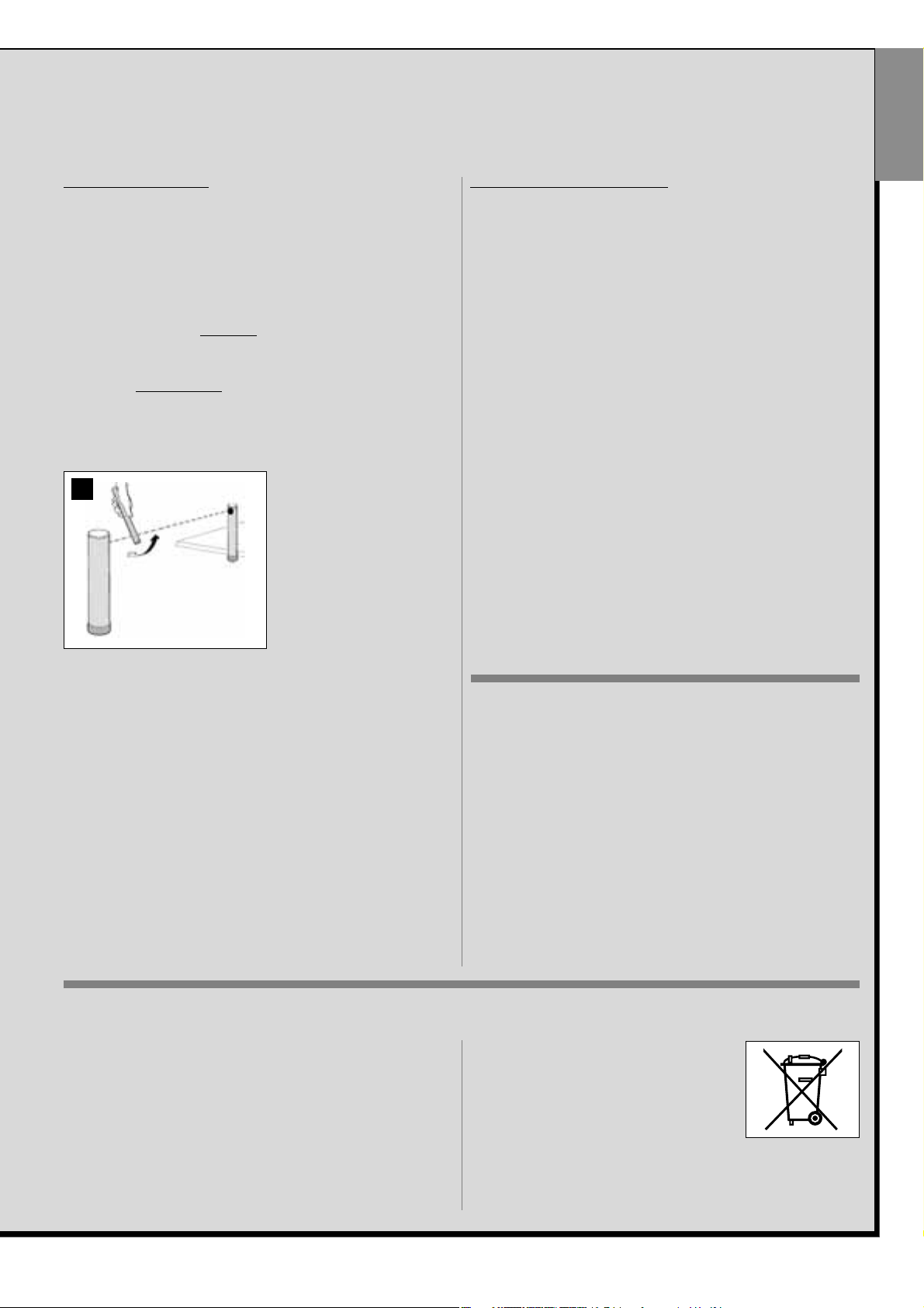
4 To check the photocells, and to ensure there is no interference with oth-
er devices, pass a cylinder (diameter 5 cm, length 30 cm) through the
optic axis joining the pair of photocells (fig. 45): pass the cylinder
first close to the TX photocell,
then close to the RX and lastly at
the centre between the two .
Ensure that in all cases the device
engages, changing from the
active status to alarm status and
vice versa, and that the envisaged action is generated in the
control unit (for example movement inversion in the Closing
manoeuvre).
5 Measure the force as specified in the standard EN 12445. If the motor
force control is used by the control unit as an auxiliary function for
reduction of impact force, adjust the functions “Leaf movement speed”
and “Leaf deceleration points” (Chapter 10) to identify the setting that
obtains the best results. CAUTION! – If the gate weighs more than 200
kg, to ensure compliance with the parameters in the standard EN
12453, a flexible edge must be fitted at the end of the gate.
6 To check operation of the buffer battery, on completion of charging, test
as follows: disconnect the power supply and after a few seconds check
that the leds and flashing light emits a series of 5 flashes. If this does
not occur, check that the battery connector is correctly inserted and
invert if necessary.
AUTOMATION COMMISSIONING
Commissioning can only be performed after positive results of all test
phases. Partial or “makeshift” commissioning is strictly prohibited.
1 Prepare the automation technical documentation, which must contain
the following documents: Overall layout drawing (see example in fig. 5),
and electrical connection layout diagram (see example fig. 17)risk
assessment and relative solutions adopted (see the website
www.moovo.com for a guide to risk assessment for different types of
gates), manufacturer’s declaration of conformity for all devices used
and the declaration of conformity compiled by the installer (see section
TECHNICAL DOCUMENTATION).
2 Affix a dataplate on the door, specifying at least the following data: type
of automation, name and address of manufacturer (responsible for
commissioning), serial number, year of construction and CE mark.
3 Prepare and provide the owner with the declaration of conformity; the
“CE Declaration of conformity” in the section TECHNICAL DOCUMENTATION must be compiled for this purpose.
4 Prepare and provide the owner with the form “Operation manual” in
the section TECHNICAL DOCUMENTATION .
5 Prepare and provide the owner with the form “Maintenance schedule”
in the section TECHNICAL DOCUMENTATION, containing all maintenance instructions for all devices in the automation .
6 Before commissioning the automation, ensure that the owner is ade-
quately informed of all associated risks and hazards.
AUTOMATION TESTING AND COMMISSIONING
These are the most important phases of automation set-up to ensure maximum system safety.
The testing procedure described can also be performed as a periodic check of automation devices.
Testing and commissioning of the automation must be performed by skilled and qualified personnel, who are responsible for the tests required to verify the solutions adopted according to the risks present, and for ensuring observance of all legal provisions, standards and regulations: and in particular
all requirements of the standard EN 12445, which establishes the test methods for checking automations for gates.
PRODUCT DISPOSAL
45
PERIODIC MAINTENANCE OPERATIONS
This product does not generally require any special maintenance; nevertheless, regular check-ups are advisable to ensure the system is in good
working order and that the safety devices installed work properly.
To carry out this maintenance correctly, please refer to the “Maintenance
Schedule”, which you will find in the “TECHNICAL DOCUMENTATION”
section at the end of the manual.
This product is an integral part of the automation and therefore must
be disposed together with the latter.
As in installation, also at the end of product lifetime, the disassembly and
scrapping operations must be performed by qualified personnel.
This product comprises various types of materials: some may be recycled
others must be disposed of. Seek information on the recycling and disposal systems envisaged by the local regulations in your area for this
product category.
Caution! – some parts of the product may contain pollutant or hazardous
substances which, if disposed of into the environment, may cause serious
damage to the environment or physical health.
As indicated by the symbol alongside, disposal of
this product in domestic waste is strictly prohibited
Separate the waste into categories for disposal,
according to the methods envisaged by current
legislation in your area, or return the product to the
retailer when purchasing a new version.
Caution! - Local legislation may envisage serious fines in the event of
abusive disposal of this product.
English

26 – English
English
TECHNICAL SPECIFICATIONS OF PRODUCT COMPONENTS
WARNINGS:
– The product LN4... is produced by Nice S.p.a. (TV) I. MOOVO is a registered trademark owned by Nice S.p.a.
– All technical specifications stated in this section refer to an ambient temperature of 20°C (± 5°C).
– Nice S.p.a. reserves the right to apply modifications to the product at any time when deemed necessary, while maintaining the same functionalities and intended use.
GEARMOTOR LN432e
DESCRIPTION DATA
Power supply
230 Vac - 50/60 Hz
Maximum absorbed power 250 W
Maximum torque 8,2 Nm
Nominal torque 3,8 Nm
low high
Speed under no load
40 Rpm 70 Rpm
Nominal speed 35 Rpm 62 Rpm
Cycles/hour at nominal
10
torque (20° C)
Cycles/hour at nominal
6
torque (50° C)
Maximum cycle frequency
5
in continuous mode
Operating temperature - 20 / + 50° C
Dimensions (mm) 288 x 264 h x 174
Weight 6 kg
Maximum admissible leaf length 5 m
Protection rating IP 44
Estimated durability (*) from 80,000 to 150,000 manoeuvre cycles
(*) Note – The estimated durability of the product ranges from 80.000 to
150.000 manoeuvre cycles. To calculate the probable durability of your
automation, proceed as follows:
a) – assess the conditions of use and force applied on your system, for
example:
• the leaf weight and length;
• perfect leaf balancing;
• maintenance conditions of the leaf hinges;
• type of leaf: solid or with many openings;
• the presence of strong winds;
• frequency of automation use.
b) – from these values, obtain a value expressed as a percentage which,
in general, defines the greatest or smallest degree of automation wear.
c) – on the graph alongside, locate the estimated percentage (at point
“b”) and read the corresponding number of manoeuvre cycles.
MF FLASHING LIGHT
DESCRIPTION DATA
Type Flashing light for automations on gates and doors
Technology adopted Luminous indicator with lamp controlled by Moovo control units with “Bus” system for automation
Lamp 12V 21W fitting BA15 (car type lamp)
Power supply The device must be connected to the “Bus” terminal of the Moovo control units for automations
Ambient operating temperature -20 ÷ 50°C
Use in acid, saline or potentially
No
explosive atmospheres
Assembly Vertical on surface or horizontal wall-mounted
Protection class IP 44
Dimensions 135 x 120h x 110 mm
Weight 340 g
100 %
75 %
50 %
25 %
0 %
80.000
90.000
100.000
110.000
120.000
130.000
140.000
150.000
English – 27
English
MT4 TRANSMITTER
DESCRIPTION DATA
Type Radio transmitters for control of automations on gates and doors
Technology adopted AM OOK radio encoded modulation
Frequency 433.92 MHz (± 100 kHz)
Coding Rolling code with 64 Bit code (18 billion, billion combinations)
Keys 4, each key can be used for different commands of the same control unit or different control units
Radiated power 1 dBm e.r.p.
Power supply 3V +20% -40% with 1 lithium battery type CR2032
Battery lifetime
3 years, estimated on the basis of 10 commands/day of the duration of 1s at 20°C
(battery efficiency is reduced at low temperatures)
Ambient operating temperature -20°C ÷ 50°C
Use in acid, saline or potentially
No
explosive atmospheres
Protection class IP 40 (use in the home or protected environments)
Dimensions 40 x 70h x 8 mm
Weight 25 g
Capacity estimated at 200 m outdoors; 35 m if inside buildings (*)
(
*
) All radio controls are subject to interference which may alter performance levels. Therefore in the event of interference, Nice cannot guarantee the effective capacity
of their devices.
MK KEYPAD
DESCRIPTION DATA
Type 5-key keypad, with possibility of activating the automation with or without entry of the code
Technology adopted Possibility of entering an activation code of up to 10 digits (over 1 million possible combinations)
Power supply / Output
The device must be connected to the Moovo “Bus” networks from which it is powered and
sends the output signals
Absorbed power 120mW in funzionamento; 45mW in stand by
Ambient operating temperature -20 ÷ 50°C
Use in acid, saline or potentially
No
explosive atmospheres
Assembly Vertical wall-mounted
Protection class IP 44
Dimensions 50 x 85h x 35 mm
Weight 80 g
MP PHOTOCELLS
DESCRIPTION DATA
Type
Presence detector for automations of automatic gates and doors (type D according to standard EN 12453)
Comprising a pair of transmitters “TX” and receiver “RX
Technology adopted Direct TX-RX optical interpolation with modulated infrared beam
Detection capacity
Opaque objects placed on optical axis between TX-RX with dimensions greater than 50mm
and speed less than 1.6m/s
TX transmission angle approx. 20°
RX transmission angle approx. 20°
Useful range
Up to 7 m for maximum TX-RX offset ±4° (the device can signal an obstacle also in the event
di condizioni meteorologiche particolarmente avverse)
Power supply / Output
The device must be connected to the Moovo “Bus” terminal from which it is powered
and sends the output signals
Absorbed power 450mW in operation; 40mW on stand by
Maximum cable length Up to 20 m (observe warnings regarding the minimum section and type of cables)
Possibility of addressing
Up to 6 detectors with safety function and up to 4 with an opening control function.
Automatic synchronisation prevents interference between the various detectors.
Ambient operating temperature -20 ÷ 50°C
Use in acid, saline or potentially
No
explosive atmospheres
Assembly Vertical on surface or horizontal wall-mounted
Protection class IP 44
Dimensions 50 x 85h x 35 mm
Weight (pair) 140 g

AVVERTENZE E PRECAUZIONI GENERALI PER LA
SICUREZZA
PASSO 1
– Operare in condizioni di sicurezza! 4
– Avvertenze per l’installazione 4
CONOSCENZA DEL PRODOTTO E PREPARAZIONE
ALL’INSTALLAZIONE
PASSO 2
2.1 - Descrizione del prodotto e destinazione d’uso 5
2.2 - Componenti utili per realizzare un impianto completo 5
PASSO 3
Verifiche preliminari all’installazione 6
3.1 - Verificare l’idoneità dell’ambiente e del cancello da automatizzare 6
3.2 - Verificare i limiti d’impiego del prodotto 6
PASSO 4
4.1 - Lavori preliminari di predisposizione 7
- 4.1.1 - Impianto tipico di riferimento 7
- 4.1.2 - Stabilire la posizione dei vari componenti 7
- 4.1.3 - Stabilire la posizione in cui installare il motoriduttore 7
- 4.1.4 - Stabilire con quale schema collegare i dispositivi 7
- 4.1.5 - Verificare gli attrezzi necessari per effettuare il lavoro 7
- 4.1.6 - Eseguire i lavori di predisposizione 8
4.2 - Preparazione dei cavi elettrici 8
INSTALLAZIONE: MONTAGGIO E COLLEGAMENTO DEI
COMPONENTI
PASSO 5
– Installare i componenti dell’automazione 9
PASSO 6
– Effettuare l’installazione e il collegamento dei dispositivi presenti nell’impianto 11
6.1 - Selezionare sulla Centrale la posizione del motoriduttore rispetto al cancello 12
6.2 - Installare e collegare il segnalatore lampeggianti mod. MF 12
6.3 - Installare e collegare il LE FOTOCELLULE mod. MP 14
– Selezione della modalità di funzionamento della coppia di fotocellule 15
6.4 - Installare e collegare la tastiera mod. MK 16
6.5 - Installare la batteria tampone mod. MB 17
ALLACCIAMENTO DELL’ALIMENTAZIONE
PASSO 7 18
PRIMA ACCENSIONE E VERIFICA DEI COLLEGAMENTI
ELETTRICI
PASSO 8 18
PROGRAMMAZIONE DELL’AUTOMAZIONE
PASSO 9
9.1 - Memorizzazione dei dispositivi collegati tramite cavo “Bus” e delle posizioni
di finecorsa “Chiusura” e “Apertura” dell’anta 19
9.2 - Memorizzazione del trasmettitore mod. MT4 20
9.3 - Programmazione della tastiera mod. MK 20
REGOLAZIONI E ALTRE FUNZIONI OPZIONALI
10 - Regolazione del funzionamento dell’automazione 21
11 - Memorizzazione di un nuovo trasmettitore con la procedura ‘in vicinanza’
della Centrale 21
12 - Cancellazione dei dati presenti nella memoria della Centrale 22
13 - Collaudo e messa in servizio dell’automazione 22
14 - Installazione e collegamento di una batteria tampone 22
COSA FARE SE... (guida alla risoluzione dei problemi) 23
ATTIVITÀ RISERVATE AD UN TECNICO QUALIFICATO
– Collegamento dell’automazione alla rete elettrica con un cavo diverso da
quello in dotazione 24
– Collaudo e messa in servizio dell’automazione 25
– Smaltimento del prodotto 25
CARATTERISTICHE TECNICHE DEI VARI COMPONENTI
DEL PRODOTTO 26
Allegati: “DOCUMENTAZIONE TECNICA” I - VII
Italiano – 3
EnglishItaliano
INDICE
AVVERTENZE E PRECAUZIONI GENERALI PER LA SICUREZZA
4 – Italiano
Italiano
requisiti essenziali di sicurezza riportati nell’ “allegato I della Direttiva Macchine”, indicando le relative soluzioni adottate. Si ricorda che l’analisi dei
rischi è uno dei documenti che costituiscono il “fascicolo tecnico” dell’automazione. Questo dev’essere compilato da un installatore professionista.
Considerando le situazioni di rischio che possono verificarsi durante
le fasi di installazione e di uso del prodotto è necessario installare
l’automazione osservando le seguenti avvertenze:
– non eseguire modifiche su nessuna parte dell’automatismo se non quelle previste nel presente manuale. Operazioni di questo tipo possono solo
causare malfunzionamenti. Il costruttore declina ogni responsabilità per
danni derivanti da prodotti modificati arbitrariamente.
– evitare che le parti dei componenti dell’automazione possano venire
immerse in acqua o in altre sostanze liquide. Durante l'installazione evitare che i liquidi possano penetrare all'interno dei motoriduttori e dei dispositivi presenti.
– se sostanze liquide penetrano all’interno delle parti dei componenti
dell’automazione, scollegare immediatamente l’alimentazione elettrica e
rivolgersi al Servizio Assistenza Moovo. L’utilizzo dell’automazione in tali
condizioni può causare situazioni di pericolo.
– non mettere i vari componenti dell’automazione vicino a fonti di calore
né esporli a fiamme libere. Tali azioni possono danneggiarli ed essere causa di malfunzionamenti, incendio o situazioni di pericolo.
– tutte le operazioni che richiedono l’apertura del guscio di protezione dei
vari componenti dell’automazione, devono avvenire con la Centrale scollegata dall’alimentazione elettrica. Se il dispositivo di sconnessione non è
a vista, apporvi un cartello con la seguente dicitura: “ATTENZIONE!
MANUTENZIONE IN CORSO”.
– il prodotto non può essere considerato un efficace sistema di protezione
contro l’intrusione. Se desiderate proteggervi efficacemente, è necessario
integrare l’automazione con altri dispositivi.
– la Centrale deve essere collegata ad una linea di alimentazione elettrica
dotata di messa a terra di sicurezza.
– il prodotto può essere utilizzato esclusivamento dopo che è stata effettuata la “messa in servizio” dell’automazione, come previsto nel paragrafo
“Collaudo e messa in servizio dell’automazione” riportato nel riquadro
“Attività riservate ad un tecnico qualificato”.
– Il materiale dell’imballaggio di tutti i componenti dell’automazione deve
essere smaltito nel pieno rispetto della normativa presente a livello locale.
PASSO 1
OPERARE IN CONDIZIONI DI SICUREZZA!
Attenzione – per la sicurezza delle persone è importante
rispettare queste istruzioni.
Attenzione – Istruzioni importanti per la sicurezza: quindi,
conservare queste istruzioni.
La progettazione, la fabbricazione dei dispositivi che compongono il
prodotto e le informazioni contenute nel presente manuale rispettano pienamente le normative vigenti sulla sicurezza. Ciò nonostante,
un’installazione e una programmazione errata possono causare gravi ferite alle persone che eseguono il lavoro e a quelle che useranno
l’impianto. Per questo motivo, durante l’installazione, è importante
seguire attentamente tutte le istruzioni riportate in questo manuale.
Non procedere con l’installazione se si hanno dubbi di qualunque natura e
richiedere eventuali chiarimenti al Servizio Assistenza Moovo.
Se questa è la prima volta che vi apprestate a realizzare un’automazione
per cancelli scorrevoli, vi consigliamo di dedicare un po’ del vostro tempo
alla lettura del presente manuale. Ciò è preferibile farlo prima di iniziare il
lavoro, senza avere fretta di iniziare con le operazioni pratiche.
Inoltre, tenere a portata di mano tutti i dispositivi che compongono il prodotto affinché possiate leggere, provare e verificare (ad esclusione delle
fasi di programmazione) tutte le informazioni contenute nel manuale.
Nel leggere questo manuale occorre prestare molta attenzione alle
istruzioni contrassegnate con il simbolo:
Questi simboli indicano argomenti che possono essere fonte potenziale di pericolo e pertanto, le operazioni da svolgere devono essere
realizzate esclusivamente da personale qualificato ed esperto, nel
rispetto delle presenti istruzioni e delle norme di sicurezza vigenti sul
proprio territorio.
AVVERTENZE PER L’INSTALLAZIONE
Secondo la più recente legislazione europea, la realizzazione di una
porta o di un cancello automatico deve rispettare le norme previste
dalla Direttiva 98/37/CE (Direttiva Macchine) e in particolare, le norme EN 12445; EN 12453; EN 12635 e EN 13241-1, che consentono di
dichiarare la presunta conformità dell’automazione.
In considerazione di ciò,
il collegamento definitivo dell’automatismo alla rete elettrica, il collaudo dell’impianto, la sua messa in servizio e la manutenzione
periodica devono essere eseguiti da personale qualificato ed esperto, rispettando le istruzioni riportate nel riquadro “Attività riservate
ad un tecnico qualificato”. Inoltre, egli dovrà farsi carico di stabilire
anche le prove previste in funzione dei rischi presenti e dovrà verificare il rispetto di quanto previsto da leggi, normative e regolamenti:
in particolare, il rispetto di tutti i requisiti della norma EN 12445 che
stabilisce i metodi di prova per la verifica degli automatismi per cancelli.
Invece, riguardo i lavori di predisposizione iniziale, d’installazione e
di programmazione, questi possono essere effettuati anche da personale non particolarmente qualificato, purché vengano rispettate
scrupolosamente e nell’ordine progressivo indicato, tutte le istruzioni riportate in questo manuale e, in particolare, le avvertenze di questo PASSO 1.
Prima di iniziare l’installazione, effettuare le seguenti analisi e
verifiche:
– verificare che i singoli dispositivi destinati all’automazione siano adatti
all’impianto da realizzare. Al riguardo, controllare con particolare attenzione i dati riportati nel capitolo “Caratteristiche tecniche”. Non effettuare
l’installazione se anche uno solo di questi dispositivi non è adatto all’uso.
– verificare se i dispositivi presenti nel kit sono sufficienti a garantire la
sicurezza dell’impianto e la sua funzionalità.
– eseguire l’analisi dei rischi che deve comprendere anche l’elenco dei
 Loading...