

Moovo KSM001 User Manual
KSM001
EN Installation and use instruc-
tions and warnings
IT Istruzioni ed avvertenze
per l’installazione e l’uso
FR Instructions et avertisse-
ments pour l’installation et
l’utilisation
ES Instrucciones y adverten-
cias para la instalación y
el uso
DE Anweisungen und Hinweise
für die Installation und die
Bedienung
PL Instrukcje instalacji i
użytkowania i ostrzeżenia
NL Aanwijzingen en aan-
bevelingen voor installering
en gebruik
Photovoltaic
power unit
Codice: IST250.4862 - Rev. 01 del 16 - 11 - 2007

English – 1
English
GENERAL SAFETY WARNINGS AND PRECAUTIONS
The design and manufacture of the devices making up the
product and the information in this manual fully comply with
current standards governing safety. However, incorrect
installation or programming may cause serious physical
injury to those working on or using the system. For this reason, during installation, always strictly observe all instructions in this manual.
If in any doubt regarding installation, do not proceed and contact
the Moovo Technical Assistance for clarifications.
WORKING IN SAFETY!
Warning – for personal safety it is important to observe
these instructions.
Warning – Important safety instructions:
Keep these instructions in a safe place.
Observe the following warnings:
– make electrical connections exclusively as envisaged in
this manual incorrect: connections could cause serious
damage to the system.
– the power cable supplied must be suitable for indoor use,
and therefore must be protected by means of a tube embedded in the wall or an external duct.
– never touch metal parts of the sockets on the battery casing with metal objects.
Considering the risk situations that may arise during installation phases and use of the product, the devices supplied in
the pack must be installed in observance of the following
warnings:
– never make any modifications to part of the devices other than
those specified in this manual. Operations other than as specified can cause malfunctions. The manufacturer declines all liability for damage caused by makeshift modifications to the product.
– never place devices near to sources of heat and never expose
to naked flames. This may damage system components and
cause malfunctions, fire or hazardous situations.
– ensure that the devices cannot come into contact with water or
other liquids. During installation ensure that no liquids penetrate
the devices present.
– the product packaging material must be disposed of in full
observance of current local legislation governing waste disposal.
Warning! – Keep this manual in a safe place to enable future
product maintenance and disposal procedures.
KNOWLEDGE OF THE PRODUCT AND PREPARATION FOR INSTALLATION
CHAPTER 1 – DESCRIPTION AND INTENDED USE
KSM001 is a system for solar power
designed for Moovo auto -
mations for gates and garage doors (fig. 1).
Any other use is to be considered improper! The manufacturer declines all liability for damage resulting from improper
use of the product and other than as specified in this manual.
This system exploits exclusively sunlight to power an automation, without use of the electrical mains.
It can supply electrical energy continuously and permanently and
can be used anywhere (for example to automate a gate situated
far from the electrical mains).
The system comprises a photovoltaic panel (mod. MSP) and an
electric battery (mod. MBB):
– the photovoltaic panel is a device able to convert sunlight
directly into electrical energy.
– the battery is a device that stores the electrical power produced by the photovoltaic panel during the hours of sunlight,
making it available at any time of the day, including days with bad
weather. This device is equipped with a carry handle, a led indicating operating status and two plugs for connection of the photovoltaic panel and the automation to be powered. The rear of
the battery is also fitted with 4 holes for wall-mounting.
CHAPTER 2 – COMPONENTS TO SET UP A COMPLETE
POWER SUPPLY SYSTEM
Fig. 2 illustrates all components used to set up a complete power supply system. The components are:
a) Photovoltaic panel mod. MSP;
b) Bracket for fixture of the photovoltaic panel;
c) Metal hardware (screws, washers, etc.);
d) Electric battery (mod. MBB);
e) Power cable for connection between the battery and auto -
mation;
f) “L” type sockets;
g) Screws for “L” type socket fixture.
• Optional Accessories (not supplied in pack)
KSM001 enables complete power autonomy of the system only
if used in full compliance with the conditions specified in Chapter
3. If these limits are exceeded – for example due to intense use
of the automation exceeding the maximum recommended number of manoeuvre cycles – the power stored by the battery may
be reduced.
For this type of problem, a power supply unit is available (mod.
MBC – optional accessory) for temporary connection to the electrical mains. This enables the user to restore full battery charge
status in just a brief time.
CHAPTER 3 – PRELIMINARY INSTALLATION CHECKS
AND PRODUCT APPLICATION LIMITS
To ascertain suitability of the product with respect to the specific
features of the automation to be powered, the following checks
should be performed as well as a check for compliance of the
technical data in the chapter “Product technical specifications”.
In the vicinity of the automation to be powered, locate the ideal
point for installation of the photovoltaic panel and the location for
2 – English
English
the battery, taking into consideration the following restraints:
a) the application limits specified in this chapter;
b) the length of the power cable (3 m) and the cable of the pho-
tovoltaic panel (3 m);
c) the space available in the vicinity of the automation to be powered.
Also check the following:
d) ensure that the selected surfaces for installation of the two
devices are solid and guarantee a stable fixture.
e) ensure that each device to be installed is in a sheltered location and protected against the risk of accidental impact.
f) in particular, for each device ensure the following:
Photovoltaic panel
– ensure that the selected panel installation site guarantees
100% direct exposure to sunlight (full sun) every day of the
year.
– ensure that the selected panel installation site is far from vegetation, walls or other situations that may create shade, even
partial, on the sensitive surfaces of the panel.
Caution! – this surface must be exposed to direct sunlight
in all points; partial shade, even if small in size (for example caused by a leaf or other object) will significantly re duce the power capacity of the panel with respect to the
values specified in graph A in this chapter.
– check the possibility of correctly positioning
and inclining the
panel, with reference to the technical instructions in Chapter 5.
Battery
To ensure optimal efficiency of the battery and prolonged battery lifetime, it should be installed in a location – in the vicinity
of the automation to be powered – protected against high
summer temperatures and low winter temperatures.
In fact the battery charge performance depends on the
ambient temperature where the battery is installed: optimal
efficiency is obtained at medium temperatures, while efficiency
is considerably reduced at low temperatures.
On the other hand, battery lifetime is influenced above all by
high summer temperatures
, which accelerate part ageing.
Normally the average lifetime is approx. 4-5 years; this also
depends on the intensity of automation use. The ideal situation
is to avoid excessive discharging of the battery due to very frequent and repetitive manoeuvre cycles over periods of time.
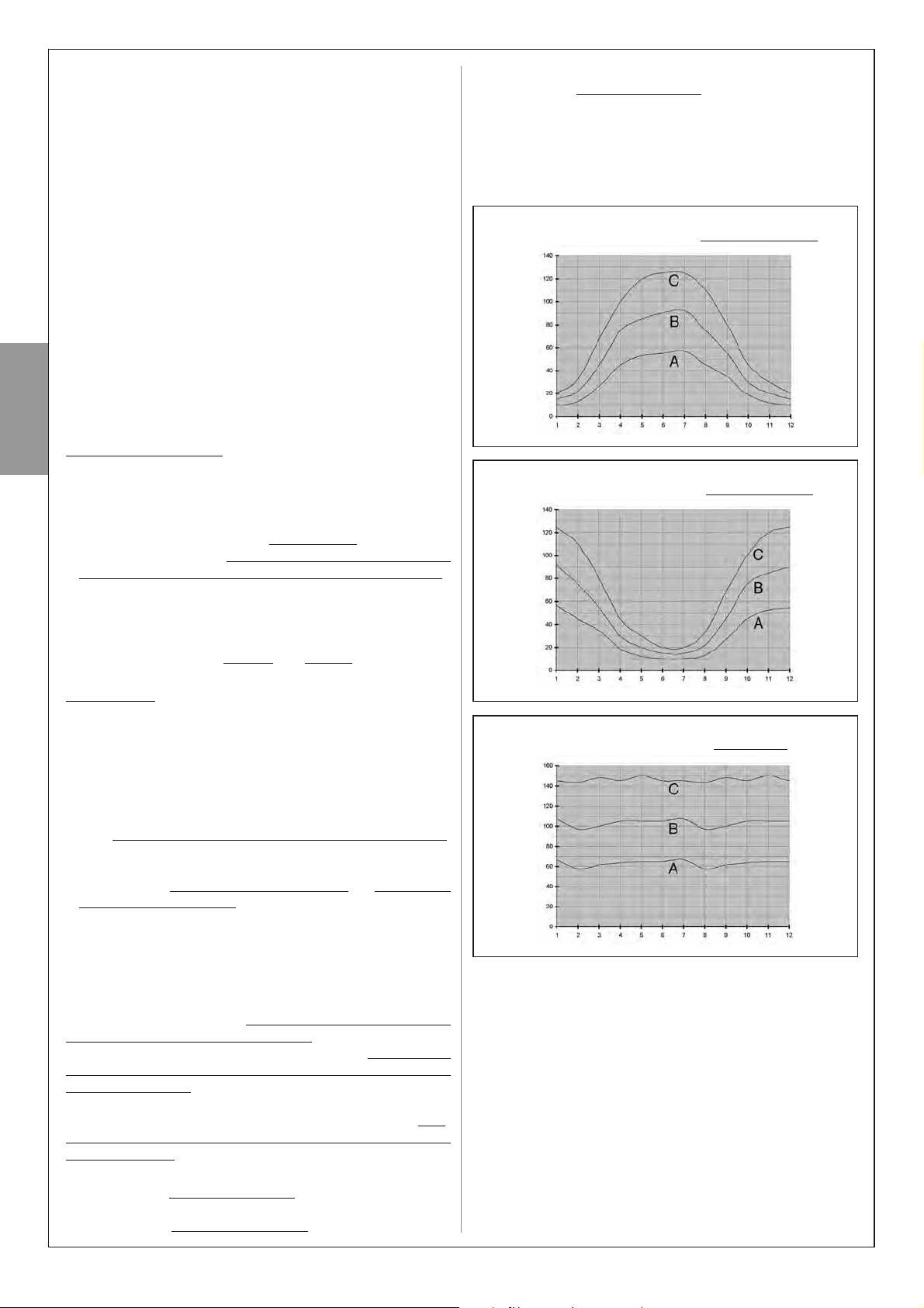
• Application limits – Graph A
Graph A indicates the maximum number of admissible manoeu
-
vre cycles
, with a MOOVO automation powered exclusively by
KSM001, at a specific time of the calendar year and on the basis
of the geographical location of the automation.
Graph A takes into consideration 3 types of gate, and for each of
these displays the curve generated by the maximum number of
manoeuvres possible in a day, in relation to 100% of the daily
hours of sunlight available in one year.
– curve “A” = heavyweight gate
(with a duration of 50 seconds
of a single manoeuvre cycle);
– curve “B” = medium weight gate
(with a duration of 40 sec-
onds of a single manoeuvre cycle);
– curve “C” = lightweight gate
(with a duration of 30 seconds of
a single manoeuvre cycle).
Warning – During the day, if the photovoltaic panel remains in
the shade for a certain period of the day (in particular from 10 am
to 2 pm) the number of operating cycles decreases in proportion
to the hours without panel exposure to sunlight.
CHAPTER 4 – BATTERY DISCHARGE
During normal automation operation the battery indicates the
battery discharged status by means of 1 sequential flash of the
led and a series of acoustic “beeps”: this signal may be temporary or permanent. In both cases, the battery must be recharged
according to one of the following procedures:
A) rapid recharge of battery using power supply unit mod. MBC
(optional accessory);
B) limiting use of the automation until lighting conditions improve
to enable the battery to recharge via the photovoltaic panel. In
both cases, the “battery discharged” warning is cleared when
the system reaches sufficient electrical autonomy to enable
automation operation.
Maximum number
of cycles per day
Months of year
GRAPH A
For countries NORTH
of the Equator
Maximum number
of cycles per day
Months of year
GRAPH A
For countries SOUTH
of the Equator
Maximum number
of cycles per day
Months of year
GRAPH A
For countries on the
Equator
English – 3
English
COMPONENT ASSEMBLY AND CONNECTIONS
CHAPTER 5
STEP 1 – Assembly of photovoltaic panel support bracket
Assemble all components of the support bracket on the rear of
the panel, as shown in fig. 3.
Caution! – The bracket at the rear of the panel must be positioned (fig. 3-b) according to the type of position in which the
panel is mounted. To select the position, refer to fig. 6.
STEP 2 – Photovoltaic panel positioning
Caution! – For optimal operation of the panel, it must be
positioned precisely in the selected location. Therefore, after
performing the checks as described in Chapter 3, strictly observe
the following instructions: as a general rule, the panel must be
positioned so that it can receive the maximum possible sunlight
during the day and throughout the year. This means that its horizontal position and vertical angle must be calculated on the basis
of the location where it is to be installed.
• Ensure the correct position of the panel on the horizontal
plane as follows:
a) In the installation site, determine the cardinal points NORTH
and SOUTH, with the aid of a compass or a geographical map of
the location.
b) Then position the panel in the direction NORTH or SOUTH,
according to the following:
– if the installation site is in a country North of the equator
(United States; Europe; Russia; etc.) the panel must be positioned exactly SOUTH
;
– if the installation site is in a country South of the equator
(Latin America; Australia; Indonesia, etc.) the panel must be
positioned exactly NORTH
.
For further information, refer to fig. 4.
• Ensure the correct position of the panel on the vertical
plane as follows:
Considering the fact that maximum efficiency of the panel is also
required in the winter period, i.e. when the daily hours of sunlight
are fewer than in the Summer, the panel should be positioned at
an angle that receives the sun rays at right angles (frontal) to the
sensitive surface.
This angle corresponds to the latitude of the location
and can be
read on any commercial geographical map. For example, Madrid
has a latitude of 40°; Venice 45°; or London approx 50° etc. For
further information, refer to fig. 5.
STEP 3 – Fixing the photovoltaic panel in the selected site
After establishing the precise position of the panel, fix to the
selected surface as shown in fig. 6.
STEP 4 – Fixing the battery in the selected site
After performing the checks as described in Chapter 3 and
establishing the precise position of the battery, fix to the selected
surface as shown in fig. 13. Note – use the 2 lower screws only
if you wish to anchor the battery in a permanent position, i.e.
when removal is not required.
STEP 5 – Cable routing
CAUTION! – For safety reasons, the operations described
in Step 5 must be performed exclusively by a skilled
and qualified technician.
After fixing the panel and battery, route the panel cable through
the tube or protection ducting through to the battery.
With reference to the instruction manual of the automation to be
powered, remove the control unit protection cover. Then pass
the end of the power cable (with wires stripped) through the
automation (where the other cables are routed) and through the
dedicated cable clamp. Then route the cable through the protection ducting (if present) through to the battery.
Caution! – Do not connect the power cable to the control unit;
leave access to the control unit open and leave the cable clamp
loose.
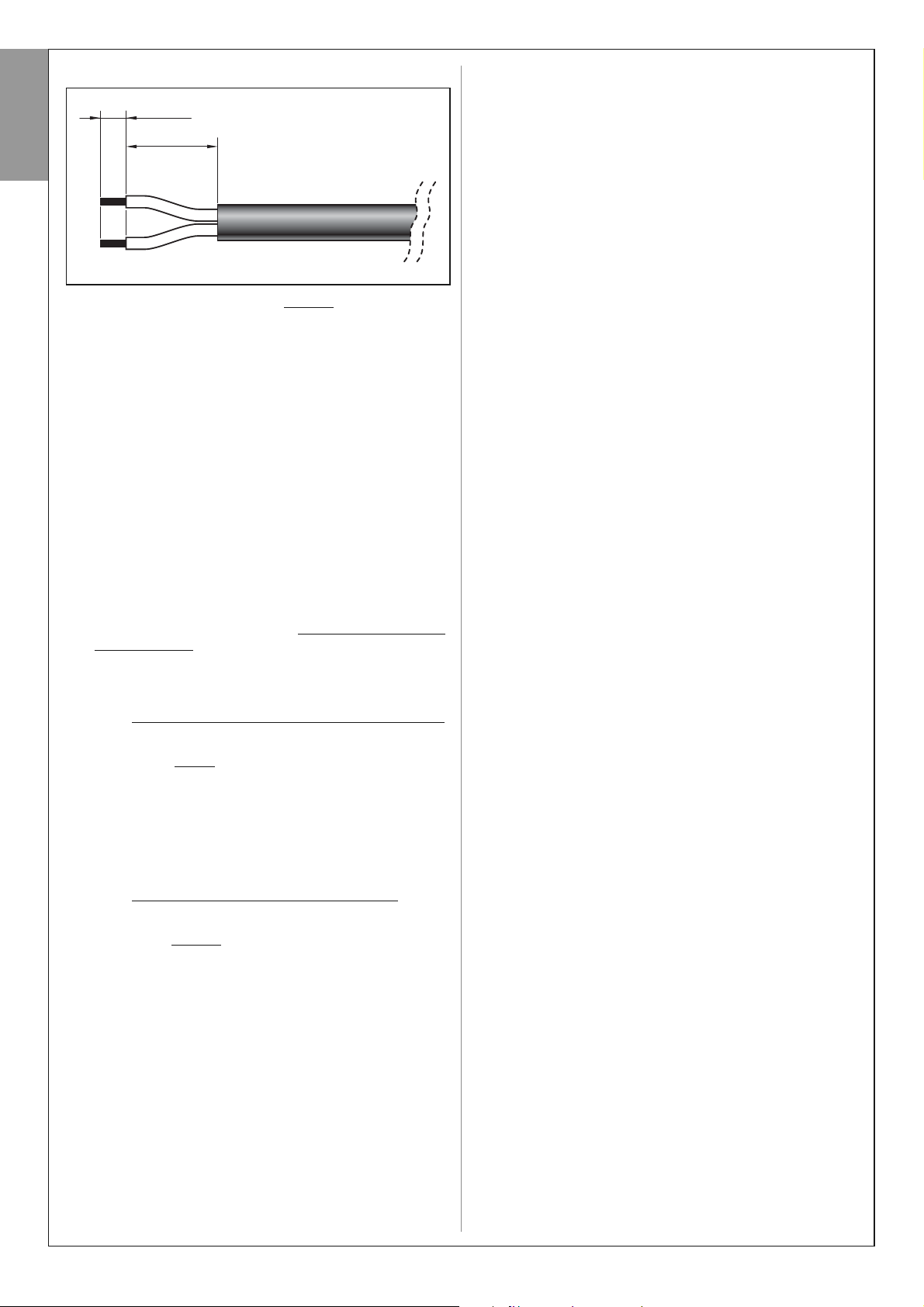
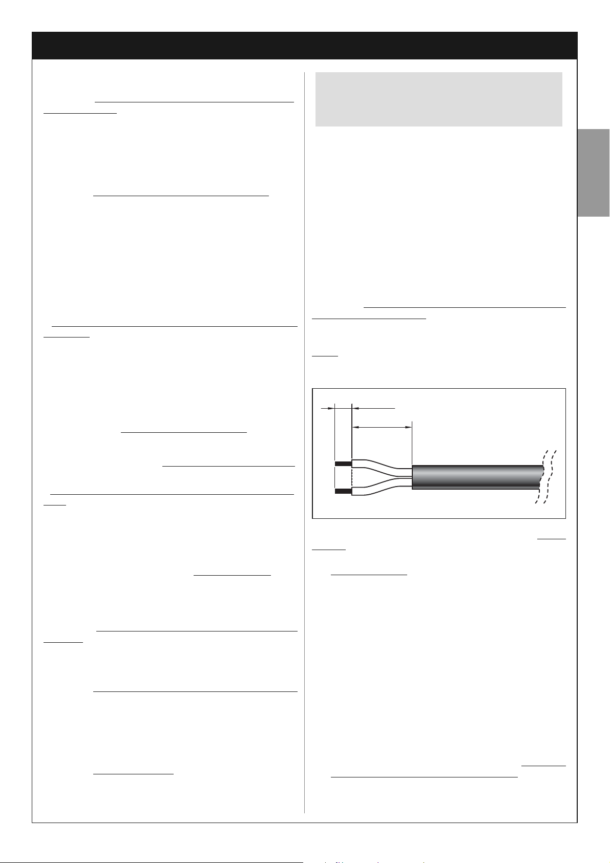
STEP 6 – Assembly of “ L” socket on the
photovoltaic pa -
nel cable
If the cable is too long, it can be shortened, taking care to strip
the wires so that their length is equa
l to the values specified in
the figure below (caution! – different lengths may impair subse-
quent assembly of the socket).
Then proceed with assembly of the GREY
“L” type socket on
the end of the panel cable, as follows:
01. Insert the various elements of the socket on the cable, tak
-
ing care to observe the sequence
as shown in fig. 7;
CAUTION! – Do not modify the electric jumper on the connector (fig. 8).
02. Using a slotted screwdriver, attach the red wire to terminal
n° 1 on the connector and black wire to the earthing terminal (4) (fig. 9):
Note – The reference numbers and symbols are printed on
the connector below the terminals and on the opposite side.
03. After fixing the two wires, insert the connector in its casing
(fig. 10).
Important – The correct position of the connector is
that with the earthing symbol in the lower position (see
fig. 10);
04. Then pull the cable outwards from the socket and insert the
seal and washer (fig. 11-a-b). Lastly, tighten the cable
clamp (fig. 11-c) using a wrench, to guarantee completely
sealed closure.
05. After assembling the socket, position the seal supplied on
the connection side (fig. 12).
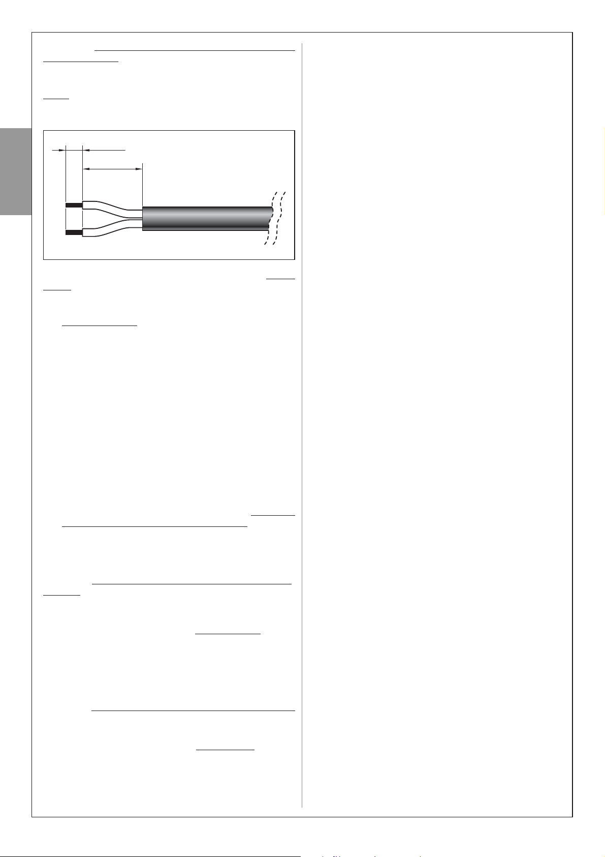
STEP 7 – Assembly of “ L” socket on the
power cable
If the cable is too long, it can be shortened, taking care to strip
the wires so that their length is equal to the values specified in
the figure below (Caution! – different lengths may impair subse-
IMPORTANT! – the power cable supplied must be suitable for indoor use, and therefore must be protected by
means of a tube embedded in the wall or an external
duct.
4 mm
10 mm
quent assembly of the socket).
Then proceed with assembly of the BLACK
“L” type socket on
the end of the power cable, as follows:
01. Insert the various elements of the socket on the cable, tak-
ing care to observe the sequence as shown in fig. 7;
CAUTION! – Do not modify the electric jumper on the connector (fig. 8).
02. Using a slotted screwdriver, attach the blue wire to termi-
nal n° 1 on the connector and the brown wire to the earth-
ing terminal (4) (fig. 9):
Note – The reference numbers and symbols are printed on
the connector below the terminals and on the opposite side.
03. After fixing the two wires, insert the connector in its casing
(fig. 10).
Important – The correct position of the connector is
that with the earthing symbol in the lower position (see
fig. 10);
04. Then pull the cable outwards from the socket and insert the
seal and washer (fig. 11-a-b). Lastly, tighten the cable
clamp (fig. 11-c) using a wrench, to guarantee
a complete-
ly sealed closure
.
05. After assembling the socket, position the seal supplied on
the connection side (fig. 12).
STEP 8 – Connecting the photovoltaic panel to the battery
To connect the panel to the battery, proceed as follows:
01. Connect the GREY
“L” type socket to the “IN” connector
on the battery (fig. 14);
02. To select the most suitable connection configuration for the
connection of all system devices, refer to the example
shown in fig. 15. Note – If frequent disconnection of the
battery plug is envisaged, use the screw in fig. 16-a. Otherwise use the screw in fig. 16-b.
STEP 9 – Connecting the battery to the automation
To connect the battery to the automation, proceed as follows:
01. Connect the BLACK
“L” type socket to the “OUT” connec-
tor on the battery (fig. 17);
02. To select the most suitable connection configuration for the
connection of all system devices, refer to the example
shown in fig. 18. Note – If frequent disconnection of the
battery plug is envisaged, use the screw in fig. 16-a. Otherwise use the screw in fig. 16-b.
03. CAUTION! – For safety reasons, the operations described in point 03 must be performed exclusively
by a skilled and qualified technician.
Access the control unit of the automation and insert the
power cable connector in the buffer battery socket on the
control unit. To locate this socket, refer to the instruction
manual of the automation to be powered.
––– General note –––
IMPORTANT – After connecting the product to the automation,
the system may not be operative immediately; this depends on
the fact that the battery may be discharged due to the natural
process of discharging over time, even when stored. In this case,
there are two ways to proceed:
A) Disconnect the battery from the automation control unit and
wait for a few days for the photovoltaic panel to receive sufficient
sunlight in order to recharge the battery;
B) Proceed with rapid recharge of battery using back-up power
supply unit mod. MBC (optional accessory).
4 – English
English
4 mm
10 mm
English – 5
English
WHAT TO DO IF... (troubleshooting guide)
• The automation control unit does not turn on and the pow-
er supply unit (mod. MBC) does not give any signal.
This may be caused by incorrect connections or electric wires
not fully inserted. Otherwise the battery may be totally discharged, in which case no signal can be sent: in this case a rapid recharge is required by means of power supply unit (mod.
MBC) or wait for the photovoltaic panel (connected correctly) to
recharge the battery.
• The battery tends to discharge too quickly.
This may be due to excessive ageing of the battery, in which
case replacement is recommended; otherwise it may be due to
excessively intensive use of the automation, over the application
limits envisaged in this manual, found in Chapter 3.
• The battery no longer recharges.
This may be due to a malfunction of the photovoltaic panel
caused by incorrect installation, incorrect cable connections, or
malfunction of the battery.
PERIODIC MAINTENANCE OPERATIONS
In general, this product does not require special maintenance;
however, regular checks over time will ensure system efficiency.
Therefore, to ensure correct maintenance, check every 6 months
that the photovoltaic panel has not accumulated dirt (leaves,
sand, etc.) as this may reduce efficiency.
Also check whether battery replacement is required, as the ageing process reduces autonomy over time.
Take into account that battery lifetime is influenced above all by
high summer temperatures
, which accelerate part ageing. Normally the average lifetime is approx. 4-5 years; this also depends
on the intensity of automation use: The ideal situation is to avoid
excessive discharging of the battery due to very frequent and
repetitive manoeuvre cycles over periods of time.
CAUTION – The battery must be replaced exclusively by
skilled and qualified personnel.
DISPOSAL
Product disposal
This product is an integral part of the automation and therefore must be disposed together with the latter.
As in installation, also at the end of product lifetime, the disassembly and scrapping operations must be performed by qualified personnel.
This product comprises various types of materials: some may be
recycled others must be disposed of. Seek information on the
recycling and disposal systems envisaged by the local regulations in your area for this product category.
Caution! – some parts of the product may contain pollutant or
hazardous substances which, if disposed of into the environment, may cause serious damage to the environment or physical
health.
As indicated by the symbol alongside, disposal of this product in domestic waste is
strictly prohibited. Separate the waste into
categories for disposal, according to the
methods envisaged by current legislation
in your area, or return the product to the
retailer when purchasing a new version.
The product also contains a lead battery,
i.e. an element that is highly pollutant if not disposed of correctly.
The battery must be removed and disposed of as specified in the
paragraph “Battery disposal”.
Caution! – Local legislation may envisage serious fines in the
event of abusive disposal of this product.
Battery disposal
Caution! – The battery contains pollutant substances and therefore must NEVER be disposed of in common waste collection
points after removal. Dispose of or recycle according to current
local standards.
6 – English
English
TECHNICAL SPECIFICATIONS OF PRODUCT COMPONENTS
WARNINGS: • The product KSM001 is produced by Nice S.p.a. (TV) I. Moovo is a commercial trademark owned by Nice S.p.a. • All technical specifications
stated herein refer to an ambient temperature of 20°C (± 5°C) • Nice S.p.a. reserves the right to apply modifications to the product at any time as deemed necessary, while maintaining the same functionalities and intended use • KSM001 guarantees a minimum of 10 manoeuvre cycles per day, exclusively with the photovoltaic panel positioned correctly and in the conditions as stated in Chapter 3, in the section “Application Limits”.
CE DECLARATION OF CONFORMITY
Note: This Declaration of Conformity contains the individual declarations of conformity for the specified products; it was updated on the issue date of this manual and the text herein has been drawn up for editorial purposes. A copy of the original declaration for each product can be requested from Nice S.p.a. (TV) I
KSM001 is produced by Nice S.p.a. (TV) I; MOOVO is a commercial trademark owned by Nice S.p.a.
The undersigned, Lauro Buoro, in the role of Managing Director, declares under his sole responsibility, that the product:
Manufacturer’s Name: NICE s.p.a.
Address: Via Pezza Alta 13, Z.I. Rustignè, 31046 Oderzo (TV) Italy
Type: MOOVO solar power kit
Models: KSM001
Accessories: No accessory
complies with the requirements of the following EC directives, as amended by Directive 93/68/EEC of the European Council of 22
July 1993:
• 89/336/EEC DIRECTIVE 89/336/EEC OF THE EUROPEAN COUNCIL of 3 May 1989 regarding the approximation of member
state legislation related to electromagnetic compatibility.
According to the following standards: EN 61000-6-2:2005, EN 61000-6-3:2001+A11:2004
The product also complies, within the constraints of applicable parts, with the following standards:
EN 60335-1:1994+A11:1995+A1:1996+A13:1998 +A14:1998+A15:2000+A2:2000+A16:2001;
EN 60335-1:2002+A1:2004+A11:2004+A2 :2006+A12 :2006
Lauro Buoro (Managing Director)
MBB BATTERY
DESCRIPTION DATA
Rated voltage: 12 V
Maximum power: 120 W
Rated battery capacity: 20 Ah
Protection rating: IP 44
Operation temperature: - 20° C, + 50° C (when charging using the back-up power supply unit: 0° C, + 40° C)
Complete recharging time: approx. 15 hours (when using the back-up power supply unit)
Dimensions: 258 mm x 235 mm x 95 mm
Weight: 8 kg
Note – The batteries used on MBB are type VRLA, “Valve Regulated Lead Acid Batteries”, i.e. sealed and valve-controlled, compliant with the specific provision A67 of the IATA/ICAAO Regulation governing hazardous products. MBB and KMS001 are therefore not considered hazardous goods
and may be transported without any risk by air, sea and on road.
MSP PHOTOVOLTAIC PANEL
DESCRIPTION DATA
Rated voltage: 17 V
Maximum power: 10 W
Operation temperature: - 40° C + 85° C
Dimensions: 310 mm x 368 mm x 18 mm
Weight: 1,9 kg
Warning – The glass of the photovoltaic panel has been tested to resist to hailstones and medium entity impact. In the event of particularly consis-
tent hail or impact, the glass may be damaged; in this case contact the moovo Technical Assistance service.
Italiano – 1
Italiano
AVVERTENZE E PRECAUZIONI GENERALI PER LA SICUREZZA
La progettazione, la fabbricazione dei dispositivi che compongono il prodotto e le informazioni contenute nel presente manuale rispettano pienamente le normative vigenti sulla
sicurezza. Ciò nonostante, un’installazione errata può causare gravi ferite alle persone che eseguono il lavoro e a
quelle che useranno l’impianto. Per questo motivo, durante
l’installazione, è importante seguire attentamente tutte le
istruzioni riportate in questo manuale.
Non procedere con l’installazione se si hanno dubbi di qualunque natura e richiedere eventuali chiarimenti al Servizio Assistenza Moovo.
OPERARE IN CONDIZIONI DI SICUREZZA!
Attenzione – Per la sicurezza delle persone è importante rispettare queste istruzioni.
Attenzione – Istruzioni importanti per la sicurezza:
quindi, conservare queste istruzioni.
Rispettare le seguenti av vertenze:
– effettuare esclusivamente i collegamenti elettrici previsti
nel presente manuale: un’errata esecuzione dei collegamenti potrebbe causare gravi danni al sistema.
– il cavo di alimentazione in dotazione è adatto ad essere
utilizzato in ambiente interno. Pertanto è obbligatorio proteggerlo con un tubo posato nel muro o con una canalina
esterna.
– non toccare con oggetti metallici le parti metalliche delle
prese che sono sull’involucro dell’accumulatore.
Considerando le situazioni di rischio che possono verificarsi
durante le fasi d’installazione e di uso del prodotto è necessario installare i dispositivi presenti nella confezione osservando le seguenti avvertenze:
– non eseguire modifiche su nessuna parte dei dispositivi, se non
quelle previste nel presente manuale. Operazioni non permesse
possono solo causare malfunzionamenti. Il costruttore declina
ogni responsabilità per danni derivanti da prodotti modificati arbitrariamente.
– non mettere i dispositivi vicino a fonti di calore né esporli a fiamme libere. Tali azioni possono danneggiarli ed essere causa di
malfunzionamenti, incendio o situazioni di pericolo.
– evitare che i dispositivi possano venire immersi in acqua o in
altre sostanze liquide. Durante l'installazione evitare che dei liquidi possano penetrare all'interno dei dispositivi.
– il materiale dell’imballaggio del prodotto deve essere smaltito
nel pieno rispetto della normativa presente a livello locale.
Attenzione! – Conservare con cura questo manuale per facilitare eventuali interventi futuri di manutenzione o di smaltimento del
prodotto.
CONOSCENZA DEL PRODOTTO E PREPARAZIONE ALL’INSTALLAZIONE
CAPITOLO 1 – DESCRIZIONE E DESTINAZIONE D’USO
KSM001 è un sistema di alimentazione a energia solare
destinato
agli automatismi Moovo per cancelli e portoni da garage (fig. 1).
Ogni altro uso è da considerarsi improprio! Il costruttore non
risponde dei danni risultanti da un uso improprio del prodotto, diverso da quanto previsto nel presente manuale.
Questo sistema sfrutta esclusivamente la luce solare per alimentare un’automazione, senza l’ausilio del collegamento alla rete
elettrica.
È in grado di erogare energia elettrica in modo continuo e permanente e può essere utilizzato ovunque (ad esempio, per automatizzare un cancello collocato lontano dalla rete elettrica).
Il sistema è composto da un pannello fotovoltaico (mod. MSP) e
da un accumulatore di energia elettrica (mod. MBB):
– il pannello fotovoltaico è un dispositivo in grado di convertire
la luce solare direttamente in energia elettrica.
– l’accumulatore è un dispositivo che immagazina l’energia elettrica prodotta dal pannello fotovoltaico durante le ore di sole e la
rende disponibile in ogni ora del giorno, compresi i giorni con
cattivo tempo. Questo dispositivo è provvisto di una maniglia per
il trasporto, un Led che segnala lo stato di funzionamento e due
spine che servono per collegare il pannello fotovoltaico e l’automatismo da alimentare. Inoltre, sul retro dell’accumulatore sono
presenti 4 fori per il suo fissaggio su una parete.
CAPITOLO 2 – COMPONENTI PER REALIZZARE UN
SISTEMA DI ALIMENTAZIONE COMPLETO
La fig. 2 mostra tutti i componenti necessari per poter realizzare
un sistema di alimentazione completo. I componenti sono:
a) Pannello fotovoltaico mod. MSP;
b) Staffa per il fissaggio del pannello fotovoltaico;
c) Minuteria metallica (viti, rondelle, ecc.);
d) Accumulatore di energia elettrica mod. MBB;
e) Cavo di alimentazione per il collegamento tra l’accumulatore e
un’automatismo;
f) Prese “a pipetta”;
g) Viti per il fissaggio della presa “a pipetta”.
• Accessori opzionali (non presenti nella confezione)
KSM001 consente la completa autonomia energetica dell’impianto solo se il prodotto viene utilizzato nel rispetto di tutte le
condizioni riportate nel Capitolo 3. Se questi limiti vengono superati, – ad esempio, a causa di un uso intenso dell’automazione
che porta a superare i cicli massimi di manovre consigliati – può
verificarsi una riduzione dell’energia immagazinata nell’accumulatore.
Per questo tipo di problema è disponibile un alimentatore (mod.
MBC – accessorio opzionale) da collegare temporaneamente
alla rete elettrica. Questo consente in breve tempo di ripristinare
completamente il livello della carica dell’accumulatore.
CAPITOLO 3 – VERIFICHE PRELIMINARI ALL’INSTALLAZIONE E LIMITI D’IMPIEGO DEL PRODOTTO
Per stabilire l’idoneità del prodotto rispetto alle caratteristiche
dell’automatismo da alimentare, effettuare le verifiche descritte in
questo capitolo e controllare la loro conformità anche in base ai

2 – Italiano
Italiano
dati tecnici riportati nel capitolo “Caratteristiche tecniche del
prodotto”.
In prossimità dell’automatismo da alimentare, individuare il punto
più adatto per installare il pannello fotovoltaico e quello più adatto per installare l’accumulatore, tenendo in considerazione i
seguenti vincoli:
a) i limiti d’impiego descritti in questo capitolo;
b) la lunghezza del cavo di alimentazione (3 m) e di quello del
pannello fotovoltaico (3 m);
c) lo spazio disponibile in prossimità dell’automatismo da alimentare.
Inoltre, effettuare le seguenti verifiche:
d) verificare che le superficie scelte per fissare i due dispositivi
siano di materiale solido e possano garantire un fissaggio stabile.
e) verificare che ciascun dispositivo da installare sia collocato in
una posizione protetta da urti accidentali.
f) in particolare, per ciascun dispositivo, verificare quanto segue:
Pannello fotovoltaico
– verificare che il luogo prescelto per l’installazione del pannello garantisca il 100% dell’insolazione diretta (pieno sole), in
qualsiasi giornata dell’anno.
– verificare che il punto prescelto per l’installazione del pannello sia lontano da vegetazione, muri o altre situazioni che possano creare zone d’ombra, anche parziali
, sulla sua superficie
sensibile. Attenzione! – questa superficie deve essere
irradiata dai raggi solari in ogni punto e in modo diretto;
un’ombra parziale, anche se di piccole dimensioni (dovuta, ad esempio, a una foglia o ad altro), riduce sensibilmente la capacità energetica del pannello, rispetto ai
valori d’impiego riportati nel grafico A di questo capitolo.
– verificare la possibilità di orientare
e inclinare correttamente
il pannello, facendo riferimento alle istruzioni tecniche riportate
nel Capitolo 5.
Accumulatore
Per ottenere dall’accumulatore un’efficienza ottimale e una
lunga durata è preferibile installare quest’ultimo, in un punto –
in prossimità dell’automatismo da alimentare – che possa proteggerlo dalle alte temperature estive e dalle basse temperature invernali.
Infatti, il rendimento della carica dell’accumulatore dipende
dalla temperatura dell’ambiente in cui questo è installato: l’effi
-
cienza ottimale si ottiene alle medie temperature
, mentre si
riduce sensibilmente alle basse temperature.
Invece, la longevità dell’accumulatore è influenzata soprat-
tutto dalle alte temperature estive
che accellerano l’invecchia-
mento delle parti
. Normalmente la vita media è di circa 4-5 anni;
questa dipende anche dall’intensità con la quale si usa l’automazione. L’ideale è non lasciare che l’accumulatore si scarichi
eccessivamente a causa di cicli di manovre ravvicinati e prolungati nel tempo.
• Limiti d’impiego – Grafico A
Il grafico A indica il numero massimo di cicli di manovre effettua
-
bili
, con un’automazione MOOVO alimentata esclusivamente
con KSM001, in un determinato momento dell’anno solare e in
base alla zona geografica in cui è presente l’automazione.
Il grafico A prende in considerazione 3 tipologie di cancelli e, per
ciascuna di queste, mostra la curva generata dal numero massi
-
mo di cicli di manovre effettuabili in una giornata
, in relazione al
100% delle ore giornaliere di sole che si hanno durante un anno.
– curva “A” = cancello di peso elevato
(con durata di 50 secon-
di del singolo ciclo di manovre);
– curva “B” = cancello di peso medio
(con durata di 40 secondi
del singolo ciclo di manovre);
– curva “C” = cancello di peso leggero
(con durata di 30 secon-
di del singolo ciclo di manovre).
Attenzione – Se durante la giornata il pannello fotovoltaico rima-
CAPITOLO 4 – ESAURIMENTO DELLA CARICA ELETRICA DELL’ACCUMULATORE
Durante il normale funzionamento dell’automazione, l’accumulatore segnala lo stato di batteria scarica con 1 lampeggio ciclico
del Led e con dei “beep” acustici: questa segnalazione può
essere temporanea o permanente. In ambedue i casi, occorre
ricaricare l’accumulatore procedendo in uno dei seguenti modi:
A) effettuare una ricarica veloce dell’accumulatore utilizzando
l’alimentatore mod. MBC, accessorio opzionale;
B) limitare l’uso dell’automazione in attesa che migliorino le condizioni di luce e permettano così la ricarica dell’accumulatore
attraverso il pannello fotovoltaico. In ambedue le circostanze, l’avviso di “batteria scarica” termina quando il sistema raggiunge una
sufficiente autonomia elettrica per far funzionare l’automazione.
ne in ombra per una parte del tempo (in particolare, dalle ore
10.00 alle ore 14.00), il numero dei cicli di funzionamento si riduce
in funzione delle ore mancanti di esposizione al sole del pannello.
Numero massimo
di cicli al giorno
Mesi dell’anno
GRAFICO A
Per i Paesi che sono a NORD
dell’Equatore
Numero massimo
di cicli al giorno
Mesi dell’anno
GRAFICO A
Per i Paesi che sono a SUD
dell’Equatore
Numero massimo
di cicli al giorno
Mesi dell’anno
GRAFICO A
Per i Paesi che sono all’
Equatore
Italiano – 3
Italiano
ASSEMBLAGGIO E COLLEGAMENTO DEI VARI COMPONENTI
CAPITOLO 5
PASSO 1 – Assemblaggio della staffa di supporto del pan
-
nello fotovoltaico
Assemblare tutti i componenti della staffa di supporto sul retro
del pannello, procedendo come mostrato in fig. 3.
Attenzione! – La staffa dietro al pannello deve essere posizionata (fig. 3-b) in funzione del tipo di posizione in cui verrà fissato il
pannello. Per scegliere questa posizione vedere la fig. 6.
PASSO 2 – Posizionamento del pannello fotovoltaico
Attenzione! – Per il buon funzionamento del pannello è ne -
cessario che questo venga posizionato con molta precisione nel punto prescelto. Quindi, dopo aver effettuato le verifiche
riportate nel Capitolo 3, seguire scrupolosamente le seguenti
istruzioni: in linea di principio, il pannello deve essere posizionato
in modo che possa ricevere il massimo della luce solare nell’arco
della giornata e nell’evolversi dell’anno. Questo significa che il
suo orientamento sul piano orizzontale e l’inclinazione sul piano
verticale devono essere calcolati in funzione del luogo in cui il
pannello viene installato.
• Definire il corretto orientamento del pannello sul piano
orizzontale, procedendo nel modo seguente:
a) Determinare sul luogo dell’installazione, i punti cardinali del
NORD e del SUD, aiutandosi con una bussola o una cartina
geografica del luogo.
b) Orientare quindi il pannello in direzione NORD o SUD, in base
alle seguenti considerazioni:
– se il luogo dell’installazione si trova in un Paese a Nord del-
l’equatore (Stati Uniti; Europa; Russia; ecc.) il pannello deve
essere orientato esattamente in direzione SUD
;
– se il luogo dell’installazione si trova in un Paese a Sud del-
l’equatore (America Latina; Australia; Indonesia; ecc.) il pan-
nello deve essere orientato esattamente in direzione NORD
.
Per maggiore chiarezza, fare riferimento alla fig. 4.
• Definire il corretto orientamento del pannello sul piano ver
-
ticale
, procedendo nel modo seguente:
Considerando che è preferibile ottenere la massima efficienza del
pannello nel periodo invernale, quando cioè le ore giornaliere di
luce solare sono minori che nell’estate, occorre orientare il pannello con un’inclinazione tale da ricevere i raggi del sole perpendicolari (frontali) alla sua superficie sensibile.
Questa inclinazione corrisponde alla latitudine del luogo
e può
essere rilevata in qualsiasi cartina geografica: ad esempio,
Madrid ha latitudine di 40°; Venezia di 45°; Londra di circa 50°
ecc. Per maggiore chiarezza, fare riferimento alla fig. 5.
PASSO 3 – Fissaggio del pannello fotovoltaico nel punto
prescelto
Dopo aver stabilito con esattezza la posizione del pannello, procedere a fissarlo sulla superficie prescelta, come mostrato in fig. 6.
PASSO 4 – Fissaggio dell’accumulatore nel punto prescelto
Dopo aver effettuato le verifiche riportate nel Capitolo 3 e stabilito con esattezza la posizione dell’accumulatore, procedere a fissarlo sulla superficie prescelta, come mostrato in fig. 13. Nota –
usare le 2 viti posizionate in basso solo se si desidera ancorare
l’accumulatore in modo fisso e non asportabile.
PASSO 5 – Passaggio dei cavi
ATTENZIONE! – Per questioni di sicurezza, le operazio-
ni descritte in questo Passo 5 devono essere eseguite
esclusivamente da un tecnico qualificato.
Dopo aver fissato il pannello e l’accumulatore, passare il cavo del
pannello attraverso il tubo o la canalina di protezione, portandolo
fino all’accumulatore.
Facendo riferimento al manuale istruzioni dell’automatismo da
alimentare, rimuovere il coperchio di protezione della Centrale di
comando. Quindi, passare attraverso l’automatismo (dove passano gli altri cavi) l’estremità del cavo di alimentazione con i fili
spelati e farlo uscire dall’automatismo attraverso il passacavo
dedicato. Infine, passare il cavo attraverso l’eventuale canalina di
protezione portandolo fino all’accumulatore.
Attenzione! – Non collegare il cavo di alimentazione alla Centrale; lasciare aperto l’accesso alla Centrale e lasciare allentato il
passacavo.
PASSO 6 – Assemblaggio della presa “a pipetta” sul
cavo
del pannello fotovoltaico
Se il cavo è eccessivamente lungo, si può accorciare facendo
attenzione a spelare i fili in modo che la loro lunghezza risulti
uguale
a quelle riportate nella figura seguente (attenzione! – lun-
ghezze diverse pregiudicano il successivo assemblaggio della
presa).
Quindi, procedere ad assemblare la presa “a pipetta” in colore
GRIGIO all’estremità del cavo del pannello, nel modo seguente:
01. Infilare sul cavo i vari elementi che compongono la presa,
rispettando l’ordine
mostrato in fig. 7;
ATTENZIONE! – Non modificare il ponticello elettrico presente
sul connettore (fig. 8).
02. Utilizzando un cacciavite a taglio, fissare sul connettore il
filo Rosso al morsetto n° 1 e il filo Nero al morsetto della presa a terra (4) (fig. 9):
Nota – I numeri e i simboli di riferimento sono stampati
sul connettore, in basso rispetto ai morsetti e sulla faccia
opposta.
03. Dopo aver fissato i due fili, procedere ad inserire il connetto-
re nella sua protezione (fig. 10).
Importante – La posizione corretta del connettore è
quella con il simbolo della presa a terra posizionato verso il basso (vedere la fig. 10);
04. Quindi, tirare il cavo verso l’esterno della presa e inserire in
questa la guarnizione e la rondella (fig. 11-a-b). Infine, avvi-
tare il pressacavo (fig. 11-c) usando una chiave, in modo da
ottenere una chiusura completamente ermetica.
05. Dopo aver assemblato la presa, posizionare sulla faccia di
connessione di quest’ultima la guarnizione in dotazione
(fig. 12).
IMPORTANTE! – Il cavo di alimentazione in dotazione è
adatto ad essere utilizzato in ambiente interno. Pertanto
è obbligatorio proteggerlo con un tubo posato nel muro
o con una canalina esterna.
4 mm
10 mm
4 – Italiano
Italiano
PASSO 7 – Assemblaggio della presa “a pipetta” sul cavo
di alimentazione
Se il cavo è eccessivamente lungo, si può accorciare facendo
attenzione a spelare i fili in modo che la loro lunghezza risulti
uguale
a quelle riportate nella figura seguente (attenzione! – lun-
ghezze diverse pregiudicano il successivo assemblaggio della
presa).
Quindi, procedere ad assemblare la presa “a pipetta” in colore
NERO all’estremità del cavo di alimentazione, nel modo se -
guente:
01. Infilare sul cavo i vari elementi che compongono la presa,
rispettando l’ordine
mostrato in fig. 7;
ATTENZIONE! – Non modificare il ponticello elettrico presente
sul connettore (fig. 8).
02. Utilizzando un cacciavite a taglio, fissare sul connettore il filo
Blu al morsetto n° 1 e il filo Marrone al morsetto della
presa a terra (4) (fig. 9):
Nota – I numeri e i simboli di riferimento sono stampati
sul connettore, in basso rispetto ai morsetti e sulla faccia
opposta.
03. Dopo aver fissato i due fili, procedere ad inserire il connettore nella sua protezione (fig. 10).
Importante – La posizione corretta del connettore è
quella con il simbolo della presa a terra posizionato verso il basso (vedere la fig. 10);
04. Quindi, tirare il cavo verso l’esterno della presa e inserire in
questa la guarnizione e la rondella (fig. 11-a-b). Infine, avvi-
tare il pressacavo (fig. 11-c) usando una chiave, in modo da
ottenere una chiusura completamente ermetica.
05. Dopo aver assemblato la presa, posizionare sulla faccia di
connessione di quest’ultima la guarnizione in dotazione
(fig. 12).
PASSO 8 – Collegamento del pannello fotovoltaico all’accu
-
mulatore
Per collegare il pannello all’accumulatore, procedere nel modo
seguente:
01. Connettere la presa “a pipetta” in colore GRIGIO
alla pre-
sa “IN” sull’accumulatore (fig. 14);
02. Fissare la presa con la vite di sicurezza in dotazione, facendo riferimento alla fig. 15. Nota – Se si prevede di scollega-
re spesso la presa dall’accumulatore, utilizzare la vite di fig.
16-a. In caso contrario, utilizzare la vite di fig. 16-b.
PASSO 9 – Collegamento dell’accumulatore all’automatismo
Per collegare l’accumulatore all’automatismo, procedere nel
modo seguente:
01. Connettere la presa “a pipetta” in colore NERO
alla presa
“OUT” sull’accumulatore (fig. 17);
02. Fissare la presa con la vite di sicurezza in dotazione, facendo riferimento alla fig. 18. Nota – Se si prevede di scollega-
re spesso la presa dall’accumulatore, utilizzare la vite di fig.
16-a. In caso contrario, utilizzare la vite di fig. 16-b.
03. ATTENZIONE! – Per questioni di sicurezza, le ope-
razioni descritte in questo punto 03 devono essere
eseguite esclusivamente da un tecnico qualificato.
Accedere alla Centrale di comando dell’automatismo ed
inserire il connettore del cavo di alimentazione nella presa
della batteria tampone presente sulla Centrale. Per indivi-
duare questa presa, fare riferimento al manuale istruzioni
dell’automatismo da alimentare.
––– Nota generale –––
IMPORTANTE – Dopo aver collegato il prodotto all’automatismo, l’impianto potrebbe non essere subito operativo; questo
dipende dal fatto che l’accumulatore potrebbe essere scarico a
causa del normale processo di autoscarica che avviene nel tempo, anche quando il prodotto è a magazzino. In questo caso è
possibile procedere in due modi:
A) Scollegare l’accumulatore dalla Centrale di comando dell’automazione e attendere qualche giorno affinchè il pannello fotovoltaico riceva sufficiente luce solare per ricaricare l’accumulatore;
B) Procedere ad eseguire una ricarica veloce e completa dell’accumulatore utilizzando l’alimentatore di emergenza mod. MBC
(accessorio opzionale).
4 mm
10 mm
Italiano – 5
Italiano
COSA FARE SE... (guida alla risoluzione dei problemi)
• La Centrale di comando dell’automatismo non si accende
e l’alimentatore (mod. MBC) non da nessuna segnalazione.
Questo potrebbe dipendere dai collegamenti non corretti o dai fili
elettrici non perfettamente inseriti. Oppure potrebbe essere l’accunulatore completamente scarico, per cui non in grado di dare
alcuna segnalazione: in questo caso è necessario operare una
ricarica rapida usando l’alimentatore (mod. MBC) o attendere
che il pannello fotovoltaico, correttamente collegato, cominci a
ricaricare l’accumulatore.
• L’accumulatore tende a scaricarsi troppo velocemente.
Questo potrebbe dipendere da un invecchiamento eccessivo dell’accunulatore per cui sarebbe opportuno sostituirlo; oppure la
causa potrebbe essere un uso troppo intensivo dell’automazione,
oltre i limiti d’impiego previsti in questo manuale, nel Capitolo 3.
• La accumulatore non si ricarica più.
Questo potrebbe dipendere da un malfunzionamento del pannello fotovoltaico a causa di una sua errata installazione; o da un
collegamento errato dei cavi; o da un malfunzionamento dell’accumulatore.
INTERVENTI DI MANUTENZIONE PERIODICA
In generale, il presente prodotto non necessita di manutenzioni
particolari; tuttavia, un controllo regolare nel tempo consente di
mantenere in efficienza l’impianto.
Quindi, per effettuare una manutenzione corretta, verificare ogni
6 mesi che il pannello fotovoltaico non abbia accumulato sporcizia (foglie, sabbia, ecc.): questa potrebbe diminuire l’efficienza.
Inoltre, è necessario verificare se è il caso di sostituire l’accumulatore che, per effetto dell’invecchiamento, potrebbe ridurre nel
tempo la sua autonomia.
Occorre tenere presente che la longevità dell’accumulatore è
influenzata soprattutto dalle alte temperature estive
che accellerano l’invecchiamento delle parti. Normalmente la vita media dell’accumulatore è di circa 4-5 anni; questa dipende anche dall’in-
tensità con la quale si usa l’automazione: l’ideale è non lasciare
che l’accumulatore si scarichi eccessivamente a causa di cicli di
manovre ravvicinati e prolungati nel tempo.
ATTENZIONE – L’eventuale sostituzione dell’accumulatore
deve essere eseguita esclusivamente da personale qualificato ed esperto.
SMALTIMENTO
Smaltimento del prodotto
Questo prodotto è parte integrante dell'automazione, e dunque, deve essere smaltito insieme con essa.
Come per le operazioni d'installazione, anche al termine della vita
di questo prodotto, le operazioni di smantellamento devono
essere eseguite da personale qualificato.
Questo prodotto è costituito da vari tipi di materiali: alcuni possono essere riciclati, altri devono essere smaltiti. Informatevi sui
sistemi di riciclaggio o smaltimento previsti dai regolamenti
vigenti sul vostro territorio, per questa categoria di prodotto.
Attenzione! – alcune parti del prodotto possono contenere
sostanze inquinanti o pericolose che, se disperse nell’ambiente,
potrebbero provocare effetti dannosi sull'ambiente stesso e sulla
salute umana.
Come indicato dal simbolo a lato, è vietato
gettare questo prodotto nei rifiuti domestici. Eseguire quindi la “raccolta separata”
per lo smaltimento, secondo i metodi previsti dai regolamenti vigenti sul vostro territorio, oppure riconsegnare il prodotto al
venditore nel momento dell'acquisto di un
nuovo prodotto equivalente.
Inoltre, il prodotto contiene un accumulatore al piombo, cioè un
elemento estremamente inquinante se non smaltito opportunamente. L'accumulatore deve essere rimosso e smaltito come
spiegato al paragrafo “Smaltimento dell’accumulatore”.
Attenzione! – i regolamenti vigenti a livello locale possono prevedere pesanti sanzioni in caso di smaltimento abusivo di questo
prodotto.
Smaltimento dell’accumulatore
Attenzione! – L’accumulatore contiene sostanze inquinanti e
quindi, non deve essere buttato nei rifiuti comuni dopo averlo
rimosso. Occorre smaltirlo o riciclarlo utilizzando i metodi previsti
dalle normative vigenti nel vostro territorio.
6 – Italiano
Italiano
CARATTERISTICHE TECNICHE DEI VARI COMPONENTI DEL PRODOTTO
AVVERTENZE: • Il prodotto KSM001 è prodotto da Nice S.p.a. (TV) I. Moovo è un marchio di Nice S.p.a. • Tutte le caratteristiche tecniche riportate, sono rife-
rite ad una temperatura ambientale di 20°C (± 5°C) • Nice S.p.a. si riserva il diritto di apportare modifiche al prodotto in qualsiasi momento lo riterrà necessario,
mantenendone comunque la stessa funzionalità e destinazione d’uso • KSM001 garantisce un numero minimo di 10 cicli di manovre al giorno, esclusivamente
con il pannello fotovoltaico correttamente orientato e nelle condizioni indicate nel Capitolo 3 alla voce “Limiti d’impiego”.
DICHIARAZIONE CE DI CONFORMITÀ
Nota: La presente Dichiarazione di Conformità raccoglie il contenuto delle singole dichiarazioni di conformità dei singoli prodotti citati; è aggiornata alla data
di edizione del presente manuale ed è stata riadattata per motivi editoriali. Copia della dichiarazione originale per ogni prodotto può essere richiesta a Nice
S.p.a. (TV) I
KSM001 è prodotto da NICE S.p.a. (TV) I; MOOVO è un marchio commerciale di proprietà di Nice S.p.a.
Il sottoscritto Lauro Buoro in qualità di Amministratore Delegato, dichiara sotto la propria responsabilità che il prodotto:
Nome produttore: NICE s.p.a.
Indirizzo: Via Pezza Alta 13, Z.I. Rustignè, 31046 Oderzo (TV) Italia
Tipo: Kit solare MOOVO
Modelli: KSM001
Accessori: Nessun accessorio
Risulta conforme a quanto previsto dalle seguenti direttive comunitarie, così come modificate dalla Direttiva 93/68/CEE del consiglio del 22 Luglio 1993:
• 89/336/CEE; DIRETTIVA 89/336/CEE DEL CONSIGLIO del 3 maggio 1989, per il riavvicinamento delle legislazioni degli Stati
membri relative alla compatibilità elettromagnetica.
Secondo le seguenti norme: EN 61000-6-2:2005, EN 61000-6-3:2001+A11:2004
Inoltre risulta conforme, limitatamente per le parti applicabili, alle seguenti norme:
EN 60335-1:1994+A11:1995+A1:1996+A13:1998 +A14:1998+A15:2000+A2:2000+A16:2001;
EN 60335-1:2002+A1:2004+A11:2004+A2 :2006+A12 :2006
Lauro Buoro (Amministratore Delegato)
PANNELLO FOTOVOLTAICO MSP
DESCRIZIONE DATI
Tensione nominale: 17 V
Potenza massima: 10 W
Temperatura d’impiego: - 40° C + 85° C
Dimensioni: 310 mm x 368 mm x 18 mm
Peso: 1,9 kg
Avvertenza – Il vetro del pannello fotovoltaico è testato per resistere alla grandine e a urti di media entità. In caso di grandine o urti particolarmente
consistenti, il vetro potrebbe danneggiarsi; in questi casi rivolgersi al Servizio Assistenza Tecnica Moovo.
ACCUMULATORE MBB
DESCRIZIONE DATI
Tensione nominale: 12 V
Potenza massima: 120 W
Capacità nominale della batteria: 20 Ah
Grado di protezione: IP 44
Temperatura d’impiego: - 20° C, + 50° C (quando è in carica con l’utilizzo dell’alimentatore di emergenza: 0° C, + 40° C)
Tempo di ricarica completa: 15 ore circa (con l’utilizzo dell’alimentatore di emergenza)
Dimensioni: 258 mm x 235 mm x 95 mm
Peso: 8 kg
Nota – Gli accumulatori utilizzati su MBB sono del tipo VRLA, “Valve Regulated Lead Acid Batteries” cioè ermetici regolati da valvola, e sono conformi alla specifica disposizione A67 del Regolamento IATA/ICAAO per le merci pericolose. MBB e KMS001 non sono quindi da considerarsi merce
pericolosa e possono essere trasportati senza alcun rischio per via aerea, via mare e su strada.
Français – 1
Français
AVERTISSEMENTS ET PRÉCAUTIONS GÉNÉRALES POUR LA SÉCURITÉ
La conception, la fabrication des dispositifs qui composent
le produit et les informations contenues dans ce guide respectent pleinement les normes en vigueur en matière de
sécurité. Toutefois, une installation incorrecte peut causer
de graves blessures aux personnes qui effectuent le travail
et à celles qui utiliseront l’installation. Pour cette raison, au
cours de l’installation, il est important de suivre attentivement toutes les instructions figurant dans ce guide.
Ne pas effectuer l’installation si le moindre doute persiste et
demander les éclaircissements nécessaires au Service aprèsvente Moovo.
OPÉRER EN CONDITIONS DE SÉCURITÉ !
Attention – pour la sécurité des personnes, il est important de respecter ces instructions.
Attention – Instructions importantes pour la sécurité :
conserver par conséquent ces instructions.
Respecter les consignes suivantes :
– effectuer exclusivement les connexions électriques prévues dans ce guide : une exécution erronée des connexions
pourrait causer de graves dommages au système.
– le câble d’alimentation fourni est adapté pour une utilisation dans un environnement fermé. Il est donc obligatoire de
le protéger avec une posée dans le mur ou avec un conduit
extérieur.
– ne pas toucher avec des objets métalliques les parties
métalliques des prises qui sont sur le boîtier de l’accumulateur.
Compte tenu des situations de risque qui peuvent se vérifier
durant les phases d’installation et d’utilisation du produit, il
faut installer les dispositifs présents dans l’emballage en
respectant les recommandations qui suivent :
– ne pas effectuer de modifications sur des parties du dispositif
quelles qu’elles soient, en dehors de celles qui sont décrites
dans ce guide. Des opérations non autorisées ne peuvent que
provoquer des problèmes de fonctionnement. Le constructeur
décline toute responsabilité pour les dommages dérivant de produits modifiés arbitrairement.
– ne pas mettre les dispositifs à proximité de fortes sources de
chaleur ni les exposer à des flammes vives ; Ces actions peuvent
les endommager et causer des problèmes de fonctionnement,
un incendie ou des situations de danger.
– éviter que les dispositifs puissent être immergées dans l’eau ou
dans d’autres substances liquides. Durant l’installation éviter que
les liquides puissent pénétrer à l’intérieur des dispositifs.
– les matériaux de l’emballage du produit doivent être mis au
rebut dans le plein respect des normes locales en vigueur.
Attention ! – Conserver avec soin cette notice pour faciliter les
éventuelles interventions futures de maintenance ou de mise au
rebut du produit.
CONNAISSANCE DU PRODUIT ET PRÉPARATION À L’INSTALLATION
CHAPITRE 1 – DESCRIPTION ET APPLICATION
KSM001 est un système d’alimentation à énergie solaire
destiné
aux automatismes Moovo pour portails et de portes de garage
(fig. 1).
Toute autre utilisation doit être considérée comme impropre ! Le constructeur ne répond pas des dommages résultant d’une utilisation impropre du produit, différente de ce
qui est prévu dans cette notice.
Ce système exploite exclusivement la lumière solaire pour alimenter un automatisme, sans branchement au secteur électrique.
Il est en mesure de fournir de l’énergie électrique de manière
continue et permanente et peut être utilisé n’importe où (par
exemple, pour automatiser un portail situé loin de l’arrivée du
courant).
Le système est composé d’un panneau photovoltaïque (mod.
MSP) et d’un accumulateur d’énergie électrique (mod. MBB) :
– le panneau photovoltaïque est un dispositif en mesure de
convertir la lumière solaire directement en énergie électrique.
– l’accumulateur est un dispositif qui stocke l’énergie électrique
produite par le panneau photovoltaïque durant les heures de
soleil et la rend disponible à toute heure du jour, y compris par
temps couvert. Ce dispositif est muni d’une poignée pour le
transport, d’une led qui signale l’état de fonctionnement et de
deux fiches qui servent à connecter le panneau photovoltaïque
et l’automatisme à alimenter. Quatre trous se trouvant sur la partie arrière de l’accumulateur servent à le fixer sur un mur.
CHAPITRE 2 – COMPOSANTS POUR RÉALISER UN
SYSTÈME D’ALIMENTATION COMPLET
La fig. 2 montre tous les composants nécessaires pour réaliser
un système d’alimentation complet. Les composants sont :
a) Panneau photovoltaïque mod. MSP ;
b) Patte pour la fixation du panneau photovoltaïque ;
c) Petites pièces métalliques (vis, rondelles, etc.) ;
d) Accumulateur d’énergie électrique mod. MBB ;
e) Câble d’alimentation pour la connexion entre l’accumulateur
et un automatisme ;
f) Fiches femelles coudées ;
g) Vis pour la fixation de la fiche femelle coudée.
• Accessoires en option (non présents dans l’emballage)
KSM001 permet l’autonomie énergétique totale de l’installation
uniquement si le produit est utilisé dans le respect de toutes les
conditions indiquées dans le Chapitre 3. Si ces limites sont
dépassées, – par exemple, à cause d’un usage intense de l’automatisme qui conduit à dépasser le nombre maximum de cycle
de manœuvres conseillés – il peut y avoir une réduction de
l’énergie stockée dans l’accumulateur.
Pour ce type de problème, il existe un bloc d’alimentation (mod.
MBC – accessoire en option) à connecter temporairement sur le
secteur électrique. Cela permet de rétablir rapidement le niveau
de charge complète de l’accumulateur.
2 – Français
Français
CHAPITRE 3 – VÉRIFICATIONS AVANT L’INSTALLATION
ET LIMITES D’UTILISATION DU PRODUIT
Pour s’assurer que le produit est adapté aux caractéristiques de
l’automatisme à alimenter, effectuer les vérifications décrites
dans ce chapitre et contrôler leur conformité également avec les
données techniques figurant dans le chapitre « Caractéristiques
techniques du produit » :
À proximité de l’automatisme à alimenter, identifier le point le
plus adapté pour installer le panneau photovoltaïque et le point le
plus adapté pour installer l’accumulateur, en tenant compte des
contraintes suivantes :
a) les limites d’utilisation décrites dans ce chapitre ;
b) la longueur du câble d’alimentation (3 m) et de celui du pan-
neau photovoltaïque (3 m) ;
c) l’espace disponible près de l’automatisme à alimenter.
De plus, effectuer les vérifications suivantes :
d) vérifier que les surfaces choisies pour fixer les deux dispositifs
sont d’un matériau solide et peuvent garantir une fixation stable.
e) Vérifier que chaque dispositif à installer se trouve dans une
position protégée, à l’abri des chocs accidentels.
f) En particulier, pour chaque dispositif, vérifier ce qui suit :
Panneau photovoltaïque
– vérifier que l’endroit choisi pour l’installation du panneau garantit
100% d’ensoleillement direct (plein soleil), tout au long de l’année.
– vérifier que le point choisi pour l’installation du panneau est
loin de la végétation, des murs ou d’autres situations qui peuvent créer des zones d’ombre, même partielle
, sur sa surface
sensible. Attention ! – cette surface doit être irradiée par
les rayons solaires en tout point et de manière directe ;
une ombre partielle, même si de petites dimensions (due,
par exemple, à une feuille ou autre), réduit sensiblement la
capacité énergétique du panneau, par rapport aux valeurs
d’utilisation indiquées dans le graphique A de ce chapitre.
– vérifier la possibilité d’orienter
et d’incliner correctement le
panneau, en se référant aux instructions techniques du Chapitre 5.
Accumulateur
Pour assurer une efficacité optimale et une longue durée de
l’accumulateur, il est préférable d’installer ce dernier à un
endroit – à proximité de l’automatisme à alimenter – en mesure
de le protéger contre les hautes températures estivales et les
basses températures hivernales.
En effet, le rendement de la charge de l’accumulateur dépend de la température de l’environnement dans lequel il est installé : l’efficacité optimale s’obtient aux moyennes températures
,
tandis qu’elle diminue sensiblement aux basses températures.
Par contre, la longévité de l’accumulateur est influencée
surtout par les hautes températures estivales
qui accélèrent le
vieillissement des parties. Normalement la vie moyenne est
d’environ 4-5 ans ; elle dépend aussi de l’intensité d’utilisation
de l’automatisme. L’idéal est de ne pas laisser l’accumulateur
se décharger excessivement à cause de cycles de manœuvres rapprochés et prolongés dans le temps.
• Limites d’utilisation – Graphique A
Le graphique A indique le nombre maximum de cycles de
manœuvres qui peuvent être effectuées, avec un automatisme
MOOVO alimenté exclusivement avec KSM001, à un moment
donné de l’année solaire et suivant la zone géographique où se
trouve l’automatisme.
Le graphique A prend en considération 3 typologies de portails
et, pour chacune d’elles, il montre la courbe générée par le nom
bre maximum de cycles de manœuvres pouvant être effectuées
dans une journée, par rapport à 100% des heures de lumière
solaire possibles sur un an.
– courbe « A » = portail de poids élevé
(avec durée de 50 secon -
des de chaque cycle de manœuvres) ;
– courbe « B » = portail de poids moyen
(durée de 40 secondes
de chaque cycle de manœuvres) ;
– courbe « C » = portail de poids léger
(avec durée de 30 secon -
des de chaque cycle de manœuvres).
Attention – Si durant la journée le panneau photovoltaïque reste
dans l’ombre pendant une partie du temps (en particulier, de
10h00 à 14h00), le nombre des cycles de fonctionnement se
réduit proportionnellement aux heures manquantes d’exposition
du panneau au soleil.
Numero massimo
di cicli al giorno
Mois de l’année
GRAPHIQUE A
Pour les pays qui se trouvent au NORD
de l’Équateur
Nombre maximum
de cycles par jour
Mois de l’année
GRAPHIQUE A
Pour les pays qui se trouvent au SUD
de l’Équateur
Nombre maximum
de cycles par jour
Mois de l’année
GRAPHIQUE A
Pour les pays qui se trouvent à l’
Équateur
CHAPITRE 4 – ÉPUISEMENT DE LA CHARGE ÉLECTRIQUE DE L’ACCUMULATEUR
Durant le fonctionnement normal de l’automatisme, l’accumulateur signale l’état de charge épuisée par 1 clignotement cyclique
de la Led et des « bips » sonores : cette signalisation peut être
temporaire ou permanente. Dans les deux cas, il faut recharger
l’accumulateur en procédant de l’une des façons suivantes :
A) effectuer une recharge rapide de l’accumulateur en utilisant le
bloc d’alimentation mod. MBC, accessoire en option ;
B) limiter l’utilisation de l’automatisme en attendant que les
conditions de lumière s’améliorent et permettent ainsi la recharge
de l’accumulateur à travers le panneau photovoltaïque. Dans les
deux cas, l’avis de « charge épuisée » cesse quand le système
atteint une autonomie électrique suffisante pour faire fonctionner
l’automatisme.
 Loading...