

Page 1
MSD Servo Drive
Operation Manual
moog
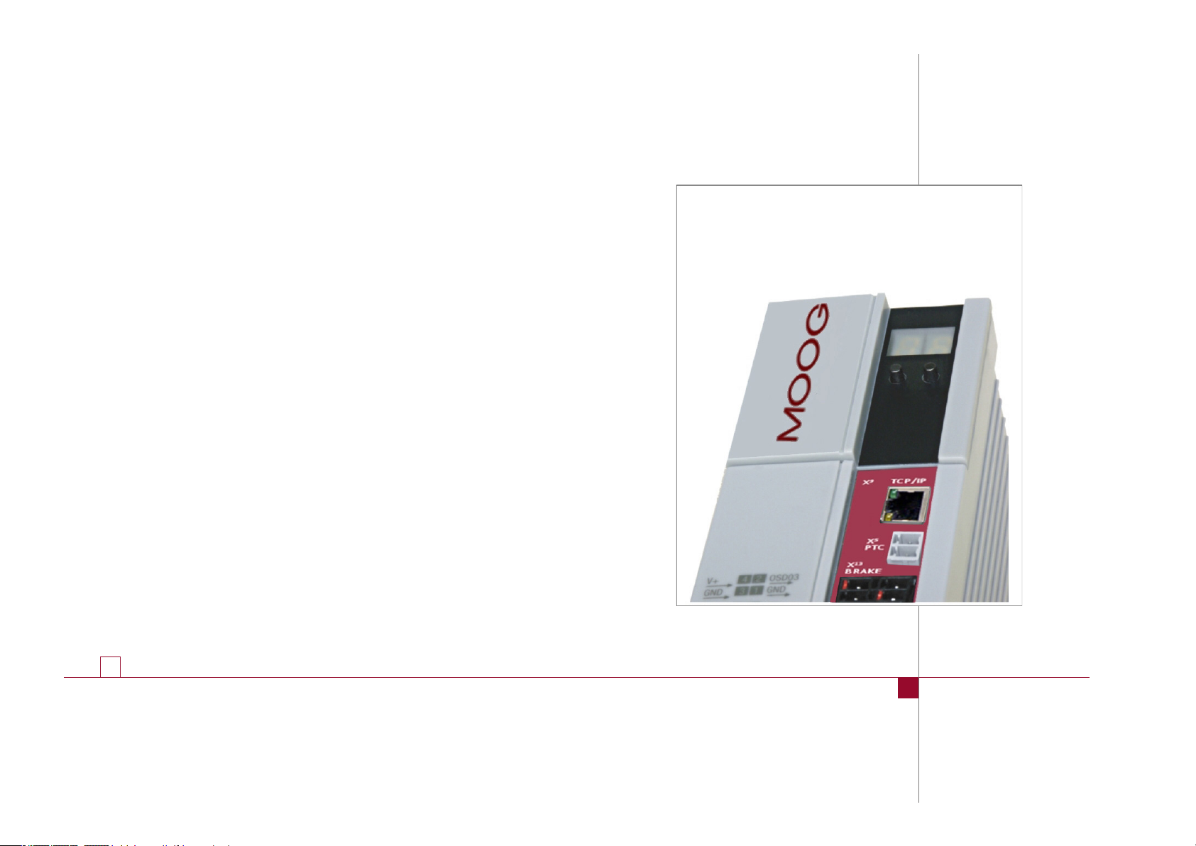
Single-Axis Servo Drive Compact
C2 to C5
2.0 A to 16.0 A
Page 2
moog
C2 C3 C4 C5
ID no.:CA97555-001 Date:04/2018
MSDSingle-Axis Servo Drive Compact Operation Manual
2
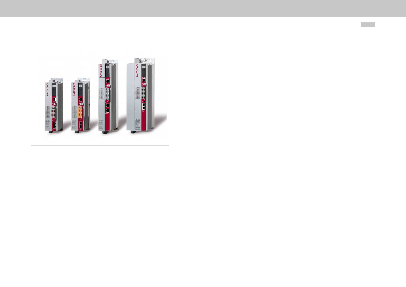
MSDSingle-Axis Servo Drive Compact high-performance drives
The modularity of the MSD Single-Axis Servo Drive Compact guarantees you optimum
integration into the machine process. Whether in high-speed eld bus communication
with the central multi-axis machine controller or with distributed programmable Motion
Control intelligence in the servo drive, the MSD Single-Axis Servo Drive Compact is a
master o
f both.
MSDSingle-Axis Servo Drive Compact Operation Manual
ID no.: CA97555-001, Rev. 5.3
Date: 04/2018
Applicable as from firmware version:V1.25-01
The German version is the original of this Operation Manual.
We reserve the right to make technical changes.
This Operation Manual has been prepared based on DIN EN 82079-1. The content
was compiled with the greatest care and attention, and based on the latest information
available to us.
We should nevertheless point out that this document cannot always be updated in line
with ongoing technical developments in our products.
Information and specications may be subject to change at any time. For information on
the latest version please visit drives-support@moog.com
Page 3

Table of contents
1 General .................................................................................... 5
1.1 Target group ............................................................................................................. 5
1.2 Prerequisites ............................................................................................................. 5
1.3 Reference documents .............................................................................................. 5
1.4 Order code ............................................................................................................... 6
1.5 Production data ........................................................................................................ 6
1.6 Scope of supply........................................................................................................ 6
1.7 Pictograms ............................................................................................................... 7
1.8 Disclaimer ................................................................................................................. 7
1.9 Disposal ................................................................................................................... 7
1.10 Helpline/Support & Ser vice Center ........................................................................... 7
2 Safety ...................................................................................... 9
2.1 O ve r v ie w .................................................................................................................. 9
2.2 For your safety .......................................................................................................... 9
2.3 General safety instructions and warnings ................................................................10
2.4 Intended use ............................................................................................................ 10
2.4.1 Repair ............................................................................................................ 11
2.5 Usage contrar y to intended use...............................................................................11
2.6 Responsibility ..........................................................................................................11
2.7 Relevant laws, standards and directives applied ..................................................... 11
2.8 Declaration of conformity .........................................................................................12
3 Mechanical installation ........................................................... 13
3.1 Notes for operation ..................................................................................................13
3.2 Wall mounting ..........................................................................................................13
3.2.1 Dimensions of the devices .............................................................................14
3.2.2 Mounting clearances .....................................................................................15
4 Electrical installation ............................................................... 17
4.1 Notes for installation ................................................................................................17
4.2 Layout .....................................................................................................................18
4.3 Connection diagram C2 to C4 .................................................................................20
4.4 Connection diagram C5 ..........................................................................................21
4.5 Effective EMC installation ....................................................................................... 22
4.5.1 Interference immunity of Servo Drives .......................................................... 22
4.5.2 Specimen setup ........................................................................................... 22
4.6 Protective earth conductor connection....................................................................25
4.7 Electrical isolation concept ......................................................................................26
4.8 Connection of the supply voltages ..........................................................................27
4.8.1 Connection of control supply (+24VDC) .......................................................27
4.8.2 Connection of mains supply .........................................................................28
4.8.3 Connected load and mains fuse ................................................................... 29
4.9 Control connections ................................................................................................31
4.9.1 Specication of control connections .............................................................31
4.9.2 Connection of motor brake X13 .................................................................... 32
4.10 Specication, Ethernet interface ............................................................................. 33
4.11 Opt i o n 1 .................................................................................................................. 33
4.12 Option 2 .................................................................................................................. 33
4.13 Encoder connection ............................................................................................... 34
4.13.1 Ready made encoder cables ....................................................................... 34
4.13.2 Resolver connection X6 ................................................................................ 35
4.13.3 Connection for high-resolution encoder ....................................................... 36
4.14 Motor connection ....................................................................................................37
4.14.1 Motor temperature sensor .............................................................................37
4.14.2 Connection of the servo motors ................................................................... 38
4.14.3 Switching in the motor cable ........................................................................ 40
moog
ID no.:CA97555-001 Date:04/2018
MSDSingle-Axis Servo Drive Compact Operation Manual
3
Page 4

moog
ID no.:CA97555-001 Date:04/2018
MSDSingle-Axis Servo Drive Compact Operation Manual
4
4.15 Brake chopper connection ..................................................................................... 40
4.15.1 Protection in case of brake chopper fault ..................................................... 40
4.15.2 Design with integrated braking resistor (C3+4+5) ......................................... 40
4.15.3 Connection of an external braking resistor ....................................................42
5 Commissioning ...................................................................... 45
5.1 Notes for operation ................................................................................................. 45
5.2 Initial commissioning .............................................................................................. 45
5.2.1 Switching on control supply ......................................................................... 46
5.2.2 Establishing connection between PC and servo drive .................................... 46
5.2.3 Setting parameters ....................................................................................... 46
5.2.4 Controlling drive using Moog Dri veAD ministr Ator5 ....................................... 46
5.3 Serial commissioning .............................................................................................. 48
5.4 Integrated control unit ............................................................................................. 48
5.4.1 Function of buttons T1 and T2...................................................................... 49
5.4.2 Display .......................................................................................................... 50
5.4.3 Parameter menu (PA).................................................................................... 50
5.4.4 Error numbers .............................................................................................. 50
5.4.5 Ethernet IP address menu (IP) .......................................................................51
5.4.6 Field bus address menu (Fb) .........................................................................52
A Appendix ............................................................................... 59
A.1 Servo drive current loads ........................................................................................ 59
A.2 Technical data MSD Single-Axis Servo Drive Compact .......................................... 62
A.3 Ambient conditions ................................................................................................. 64
A.4 UL certication ....................................................................................................... 65
Glossary ........................................................................................ 67
6 Diagnostics ............................................................................ 55
6.1 Device states .......................................................................................................... 55
6.2 Error indication ....................................................................................................... 55
6.3 Error codes ............................................................................................................. 55
6.4 Helpline/Suppor t&Service .................................................................................... 56
7 Safe Torque Off (STO) ............................................................ 57
Page 5
MSDSingle-Axis Servo Drive Compact Operation Manual
moog
1 General
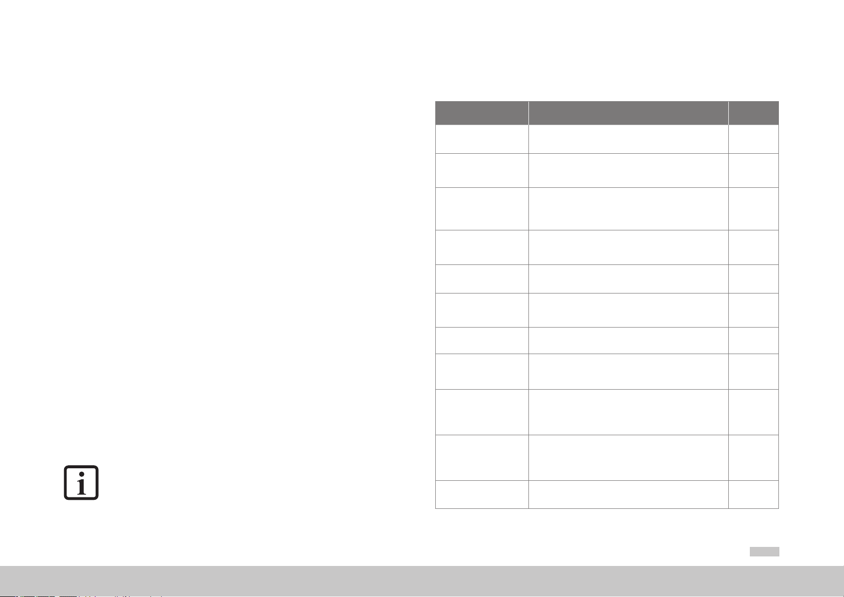
1.3 Reference documents
The product CD from Moog contains the complete documentation for the related
product series. The documentation for a product series includes the Operation Manual
(hardware description), Device Help (software description) as well as further User
Manuals (e.g. field bus description) and Specifications. They are available in the formats
PDF, HTML or chm.
1.1 Target group
Dear user,
the documentation forms part of the device and contains important information on
operation and service. It is aimed at all persons who undertake mounting, installation,
commissioning and servicing work on the product.
1.2 Prerequisites
Prerequisites for the usage of devices from Moog:
y The documentation on the devices is to be stored so it legible, accessible at all times and for the
entire life of the product.
y Read and ensure you under Date the documentation on your device.
y Qualication: to prevent injury or damage, personnel may only work on the device if they have
electrical engineering qualications.
y Knowledge required:
− National health and safety regulations (e.g. VBG 4 in Germany)
− Mounting, installation, commissioning and operation of the device
Work in other areas, for example transport, storage and disposal is only allowed to be
undertaken by trained personnel.
NOTE
This Operation Manual applies to the MSD Single-Axis Servo Drive Compact
(referred to in the following as the servo drive). This manual does not replace the
Operation Manuals for the MSD Single- and Multi-Axis Servo Drive.
Document Contents
MSD Servo Drive
Single-Axis Servo Drive
Compact - Operation Manual
MSD Servo Drive
AC-AC Servo Drive
Single-Axis System Operation Manual
MSD Servo Drive
DC-AC Servo Drive
Multi-Axis SystemOperation Manual
MSD Power Supply Unit
Multi-Axis SystemOperation Manual
MSD Servo Drive
SERCOS II User Manual
MSD Servo Drive
SERCOS III User Manual
MSD Servo Drive Field bus
systems CANopen/EtherCAT User Manual
MSD Servo Drive
Field bus systems
Profibus/Profine
User Manual
Modular Multi-Axis Servo
Drive System - MSD Ordering Catalog
MSD Servo Drive - Device
Help
Program help
D
riveADminsitrAtor 5
Moog
PC user software
Safety, mechanical installation, electrical installation,
commissioning, diagnostics, specifications certification and
applicable standards, technical data
Safety, mechanical installation, electrical installation,
commissioning, diagnostics, specifications certification and
applicable standards, technical data
Safety, mechanical installation, electrical installation, commissioning,
diagnostics, STO, operation with AC-AC Servo Drive as supply,
planning, application example, specifications certification and
applicable standards, technical data
Safety, mechanical installation, electrical installation, commissioning,
diagnostics, specification certification and applicable standards
technical data
Safety, commissioning, communication phases, parameter interface,
error, warning and status messages, operation modes, weighting,
referencing, touchprobe, parameter lists
Safety, installation and connection, commissioning and configuration
parameterisation, data transmission, scaling and weighting,
functionality, error message and diagnostics, parameter lists
Safety, commissioning, data transmission, operation modes,
referencing, parameters, technical data
Description and configuration of the parameters for the MSD Se vo
Drive on the PROFIBUS/PROFINET field bus syste
Information, notes on ordering, specifications and
technical data on:
MSD Single-Axis Servo Drive Compact, MSD Single-Axis System,
MSD Multi-Axis System, safety technology, communication,
technology, function packages, accessories and motors
Description of the software functionality MSD Servo Drive,
firmware versions
- MSD Single-Axis Servo Drive Compact from V1.30-xx
- MSD Single-Axis System from V3.25-xx
- MSD Multi-Axis System from V3.25-xx
Context-sensitive help for Moog DriveADministrAtor version 5.x
graphic PC user software for initial commissioning and serial
commissioning, operation, diagnostics and project management
ID no.
Format
CA97555-001
PDF
CA65642-001
PDF
CA97554-001
PDF
CA97556-001
PDF
CA65648-001
PDF
CA97557-001
PDF
CA65647-001
CA65645-001
PDF
CDL 29950-en
PDF
CB40859-001
PDF and
HTML
CB19692-001
ID no.:CA97555-001 Date:04/2018
5
Page 6
moog
ID no.:CA97555-001 Date:04/2018
MSDSingle-Axis Servo Drive Compact Operation Manual
6
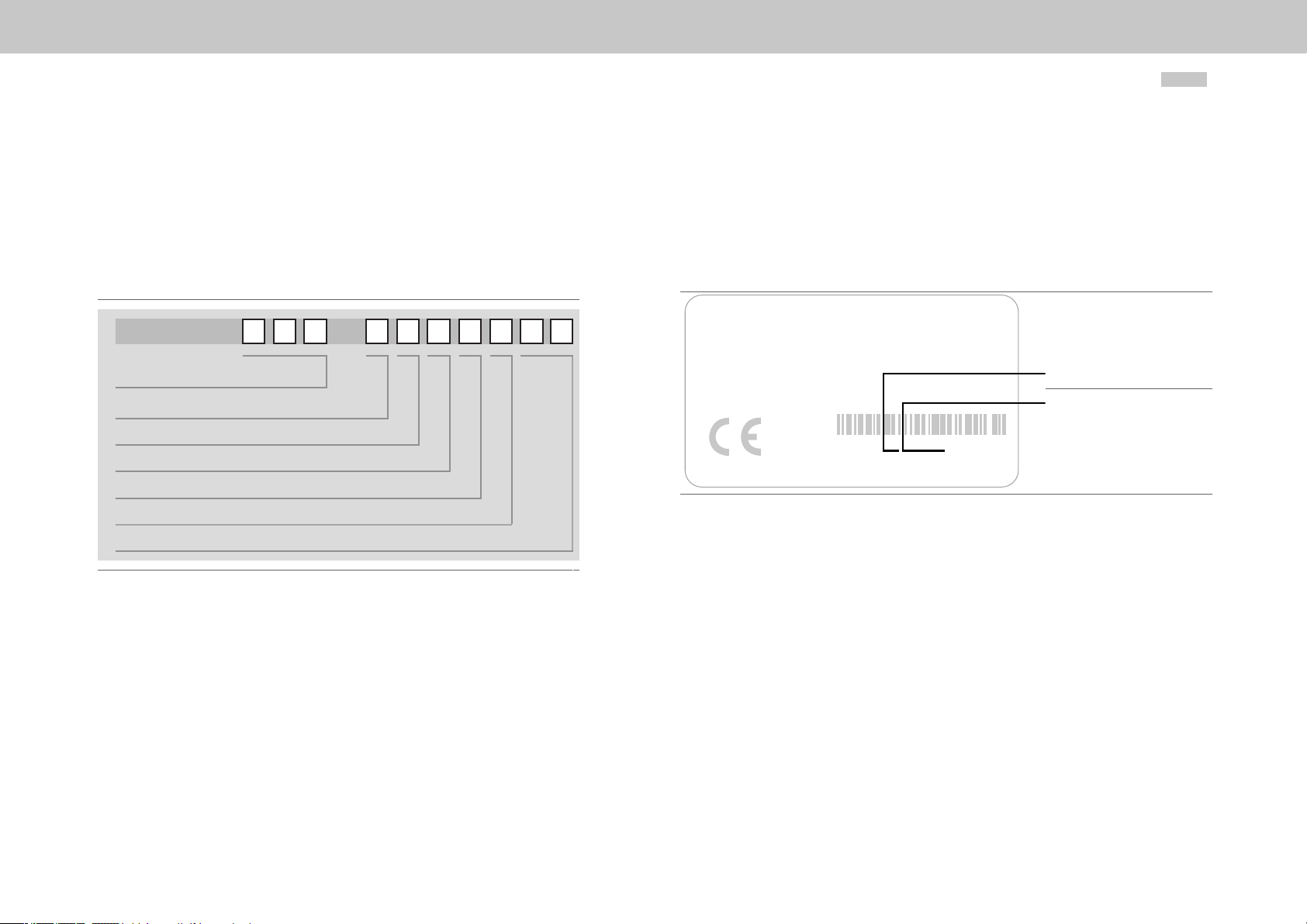
1.4 Order code
The MSD Single-Axis Servo Drive Compact has the article designation
G394-xxx-xxx-xxx. The provides information on the related variant of the supplied
MSD Servo Drive. The signicance of the individual characters of the article designation
is given in the following order code.
You will nd the complete order code with all values in the MSD Ordering Catalog.
G394 -
Rated current
Option 1 (Communication)
Option 2 (Technology)
Option 3 (Safety)
Option 4 (Function package)
Modificatio
Variants
- -
1.5 Production data
On rating plates for the MSD Single-Axis Servo Drive Compact you will nd the serial
number, from which you can identify the date of manufacture based on the following
key. For the location of the rating plate on the servo drive refer to "Figure 4.1 Layout
MSD Single-Axis Servo Drive Compact C2 to C4" and "Figure 4.2 Layout MSD SingleAxis Servo Drive Compact C5".
MOOG
D-71034 Böblingen
www .moog.com/industrial
Made in Germany
Model:: G394-030-210-001
S/N:D116605 Rev. A
In: 230 V AC 3ph, 50/60 Hz
4,0 A
0-230 V AC 3ph, 0-400 Hz
Out:
3,0 A
Year of production
Week of production
ID : JJWWxxxxx
Fig. 1.1 MSD Single-Axis Servo Drive Compact hardware rating plate
1.6 Scope of supply
The scope of supply includes:
y MSD Single-Axis Servo Drive Compact
y Terminal kit for control and power terminals
(depending on device power and variant)
Set with shield connecting plates and xing material
y
Product CD with booklet
y
Page 7

MSDSingle-Axis Servo Drive Compact Operation Manual
moog
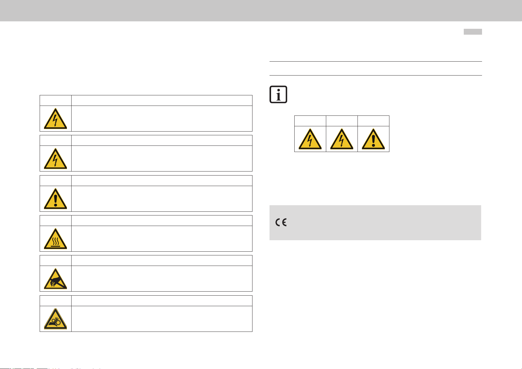
1.7 Pictograms
1.10 Helpline/Support & Service Center
The pictograms used in this Operation Manual signify the following for the user:
NOTE
Useful information or reference to other documents.
1.
(digit)
You will nd the pictogram used in this Operation Manual for "General safety instructions and warnings" in chapter "2 Safety".
ACTION TO BE TAKEN
Processing step undertaken by the user or the system.
1.8 Disclaimer
Following the documentation on the devices from Moog GmbH is a prerequisite:
y For safe operation.
y To achieve stated performance features and product characteristics.
Moog GmbH does not accept any liability for injuries, damage or nancial losses that
result from the failure to follow the documentation.
1.9 Disposal
Follow the applicable national regulations! If necessary, dispose of individual parts,
depending on their characteristics and existing national regulations, e.g. as:
y Electrical waste
y Plastic
y Metal
Or engage a certied disposal organisation with scrapping
Our Helpline will help you with fast, specic assistance if you have any technical queries
relating to project planning or commissioning your device.
Address: Moog GmbH
Hanns-Klemm Straße 28
D-71034 Böblingen
The Helpline is available by e-mail, telephone or telefax:
E-Mail: drives-support@moog.com
Phone: +49 7031 622 0
Telefax: +49 7031 622 100
If you need further assistance, our specialists at the Service & Support Center will be
happy to help.
E-Mail: info.germany@moog.com
Phone: +49 7031 622 0
ID no.:CA97555-001 Date:04/2018
7
Page 8

moog
ID no.:CA97555-001 Date:04/2018
MSDSingle-Axis Servo Drive Compact Operation Manual
8
Page 9

2 Safety
2.1 Overview
Our devices are state-of-the-art and comply with recognised safety regulations,
nevertheless hazards can arise. In this chapter:
y We provide information on residual risks and hazards that can emanate from
our devices on usage as intended.
y We warn about the foreseeable misuse of our devices.
y We refer to the necessary care and measures to be taken to prevent risks.
2.2 For your safety
NOTE
Only install and place in operation your device taking into account the
documentation for the related device family!
Our devices are quick and safe to operate. For your own safety and for the safe
functioning of your device, please be sure to observe the following points:
3.
4.
5.
Protection against magnetic and/or electromagnetic fi lds during
installation and operation.
Persons t ted with heart pacemakers, metallic implants and hearing aids etc. must not be allowed
access to the following areas:
• Areas in the immediate vicinity of electrical equipment!
• Areas in which electronics components and Ser vo Drives are installed,
repaired and operated!
• Areas where motors are installed, repaired and operated!
Motors with permanent magnets pose particular hazards.
During installation observe the following:
• Comply with connection conditions and technical data as per the documentation and the
rating plate!
• Comply with standards and directives on electrical installation, such as cable cross-section,
shielding, etc.!
• Do not touch electronic components and contacts!
Electrostatic discharge can harm people and destroy components!
• Take protection measures and use protective devices as per the applicable regulations
(e.g. IEC/EN60204 or IEC/EN 61800-5-1)!
• Take "device earthing" protection measure!
Ambient conditions
Follow the instructions on the transport, storage and correct operation of the devices stated in
•
the Operation Manual in "A Appendix".
1.
2.
Follow safety instructions for the devices:
Follow all safety instructions and warnings in the entire documentation related to the device series.
Electric drives are dangerous:
• Due to electrical voltages up to 480V AC and up to 800 V DC
• Dangerously high voltages of ≥50V may still be present 10min. after the power is cut
(capacitor charge). So check that electrical power is not present! See also the warning label on
the front panel on the device.
• Rotating parts
• Automatically starting drives.
• Hot components and surfaces
moog
ID no.:CA97555-001 Date:04/2018
MSDSingle-Axis Servo Drive Compact Operation Manual
9
Page 10
moog
ID no.:CA97555-001 Date:04/2018
MSDSingle-Axis Servo Drive Compact Operation Manual
10
2.3 General safety instructions and warnings
Hazards may emanate from our devices. For this reason it is imperative you follow the
safety instructions and warnings in this document.
DANGER! Risk of injury due to electrical power!
• Carelessness will result in serious injuries or death.
Follow safety instructions and warnings in this document and on the device.
WARNING! Risk of injury due to electrical power!
• Carelessness may result in serious injuries or death.
Follow safety instructions and warnings in this document and on the device.
CAUTION! Risk of injury or damage to the device due to incorrect operation!
• Carelessness may result in minor injuries or
damage.
Follow safety instructions and warnings in this document and on the device.
WARNING! Risk of injury due to hot surfaces and components!
• Carelessness may result in serious burns.
Electronic components may become hot during operation!
Follow safety instructions and warnings in this document and on the device!
Caution! Damage due to electrostatic discharge!
• Electrostatic discharge can destroy components.
Do not touch electronic components and contacts!
Follow safety instructions and warnings in this document and on the device!
DANGER! Risk of injury due to rotating par ts on the motor!
• Carelessness will result in serious injuries or death.
Follow safety instructions and warnings in this document.
Pay attention to special safety instructions and warnings that are given here in the document
before a specic action and that warn the user about a specic hazard!
NOTE:
The pictograms may also be used on their own with the signal word, e.g.
in the connection diagrams, however they have the same function as in the
complete warning.
DANGER WARNING CAUTION
2.4 Intended use
Our devices are components intended for stationary electrical systems and machines in
the industrial and commercial sector.
The devices in the product range MSD Single-Axis Servo Drive Compact conform to the
Machinery Directive 2006/42/EC
Tested and certied in accordance with applicable standards (see declaration of conformity
in chap. 2.8).
When installed in machines it is prohibited to start-up intended operation until it has
been ascertained that the completed machine fully complies with the provisions of
the Machinery Directive (2006/42/EC); compliance with IEC/EN60204 is mandatory.
Starting up intended operation is only permitted on compliance with the EMC Directive
2014/30/EU.
The devices full the demands of the harmonised product standard IEC/EN61800-5-1.
You will find information on the installation of your device in chapter "3 Mechanical
installation".
Page 11

2.4 .1 Repair
Only have repairs undertaken by authorised repair shops. Unauthorised opening and
incorrect intervention could lead to death, physical injury or material damage. The
warranty provided by Moog would thereby be rendered void.
2.5 Usage contrary to intended use
Our devices are:
y Not intended for installation in vehicles. Deployment of the device in non-
stationary equipment is classed as non-standard ambient conditions, and is
permissible only by special agreement.
y Not intended for installation in environments with harmful oils, acids, gases,
vapours, dusts, radiation etc.
y Not approved for usage in special applications (e.g. in potentially explosive
atmospheres or areas in which there is a risk of re).
y Not approved for usage outside a cabinet
y Not approved for the generation of high-frequency onboard
networks for which the device is not designed
2.6 Responsibility
Pay attention to the topic of “Electrical equipment of machines” in IEC/EN60204-1:
2006 “Safety of machinery”. The safety requirements on electrical machines dened
there are intended to protect personnel and machinery or systems.
The emergency stop function (as per IEC/EN 60204) shuts down the supply of power
to a machine, which results in the drives coasting down in an uncontrolled manner. To
avert hazards, check whether it is appropriate:
− To keep individual drives in operation
− To initiate specic safety procedures
− To incorporate a Safe Torque Off function (Safe Torque Off: movement stop
by "switching off the electrical supply" - STO)
2.7 Relevant laws, standards and directives applied
For information on the laws, Dateards and directives applied by Moog, refer to the
declaration of conformity.
NOTE:
Depending on the specic application for the devices, other laws, standards
and directives with provisions on "Safety" may apply. If necessary, contact
the machine or system manufacturer.
Electronic devices are fundamentally not fail-safe. The installer and/or operator of a
complete machine or system is responsible for ensuring:
y That the drive is rendered safe if the device fails
y The safety of personnel and machinery
y The complete machine is in correct working order
For the risk assessment on the complete machine or system according to
y
EN ISO 12100 (formerly EN ISO 14121) and EN ISO 13849-1
(formerly DIN EN 954-1)
moog
ID no.:CA97555-001 Date:04/2018
MSDSingle-Axis Servo Drive Compact Operation Manual
11
Page 12
moog
ID no.:CA97555-001 Date:04/2018
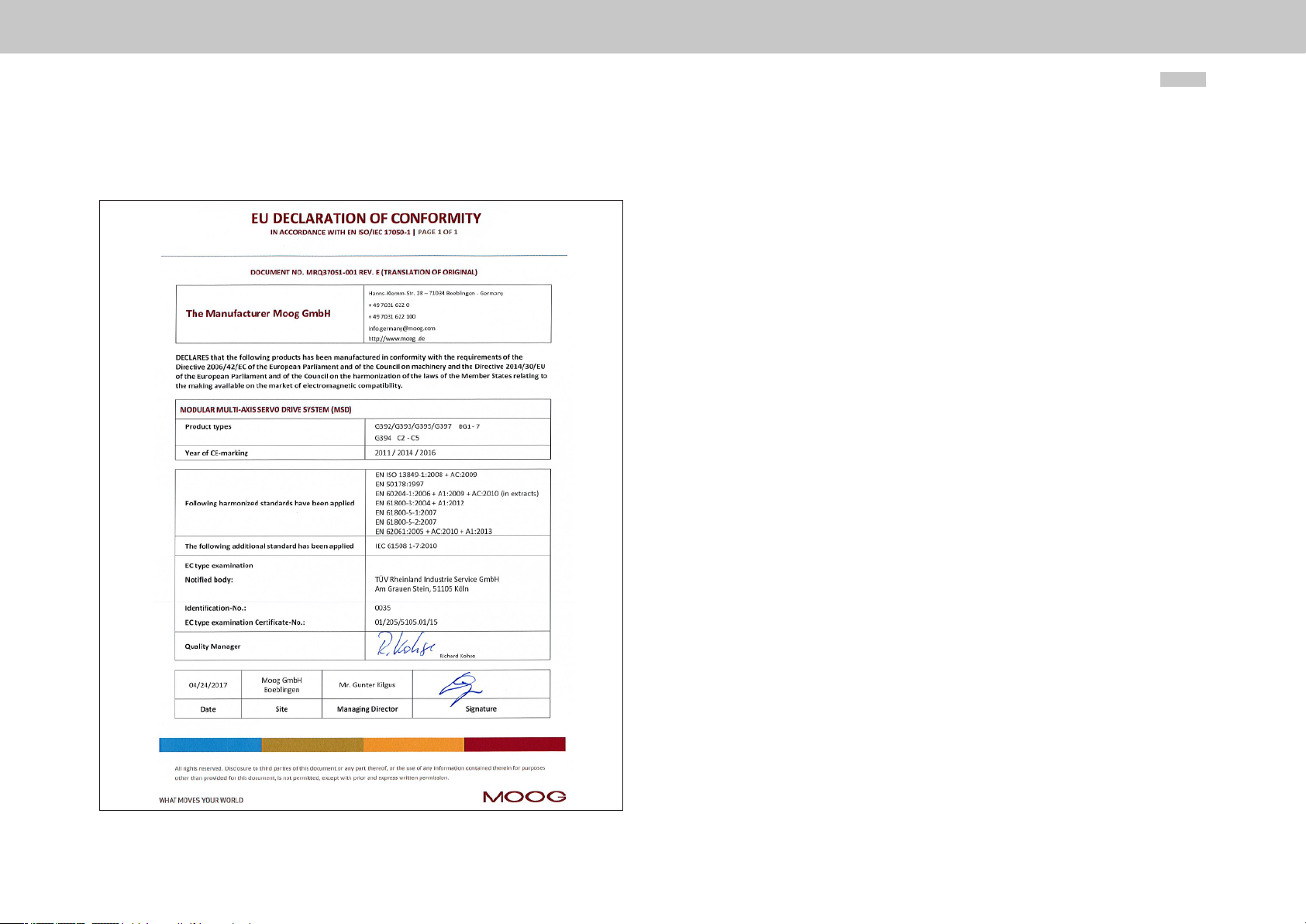
2.8 Declaration of conformity
MSDSingle-Axis Servo Drive Compact Operation Manual
12
Page 13
3 Mechanical installation
3.2 Wall mounting
Step Action Comment
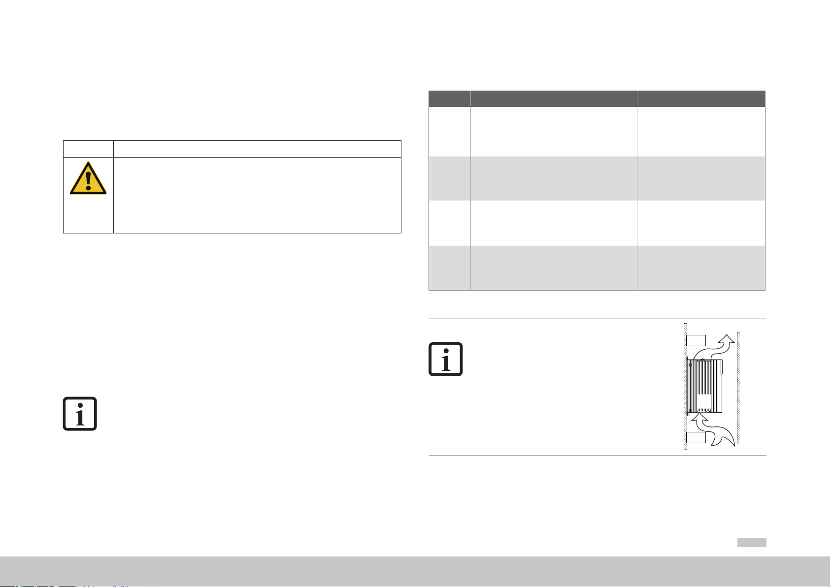
3.1 Notes for operation
CAUTION Damage to the device due to incorrect installation conditions!
The device may be destroyed
For this reason
• Moisture must not be allowed to enter the device
• There must not be any aggressive or conductive substances in the ambient air
• Foreign bodies such as drilling chips, screws, washers etc. must not be allowed to enter
the device
• The ventilation openings must not covered
Note the following points:
y Cooling air must be able to ow through the device without restriction.
y For mounting in switch cabinets with convection (= heat loss is discharged to the outside via the
cabinet walls), always t an internal air circulation fan.
y The backing plate must be well-earthed.
y The device is designed only for vertical installation in switch cabinets. The switch cabinet must
as a minimum provide IP4x protection.
y To attain the best result for EMC-compatible installation you should use a chromated or
galvanized backing plate. If backing plates are varnished, remove the coating from the contact
area! The devices themselves have an aluminium back panel.
y Maximum pollution degree 2
NOTE
According to ENISO13849-2 the switch cabinet must have IP54 protection
or higher on using the STO (Safe Torque OFF) safety function.
Further information on environmental conditions can be found in the appendix.
Mark out the position of the tapped holes on the
backing plate.
1.
Cut a thread for each xing screw in the backing plate.
Mount the servo drive vertically on the backing
2.
3.
4.
Table 3.1 Mechanical installation
.
plate
Mount the other components, suchas the mains lter,
mains choke etc., on the backing plate.
Continue with the electrical installation in chapter 3.
NOTE
Forced cooling by external air ow is necessary
for all sizes of the MSD Single-Axis Servo
Drive Compact. The air must be able to ow
unhindered through the device. If a temperature
cut-out occurs, the cooling conditions must be
improved.
Air ow: minimum 1.2 m/s (3.93 ft/s)
Dimensional drawings/hole spacing see
Figure 3.1, Figure 3.2
The thread sur face area will provide you
with good, full-area contact.
Observe the mounting clearances! The
contact area must be bare metal.
The cable between mains lter and servo
drive may be 300mm (11.81in) long.
moog
ID no.:CA97555-001 Date:04/2018
MSDSingle-Axis Servo Drive Compact Operation Manual
13
Page 14
moog
C1
A1
ID no.:CA97555-001 Date:04/2018
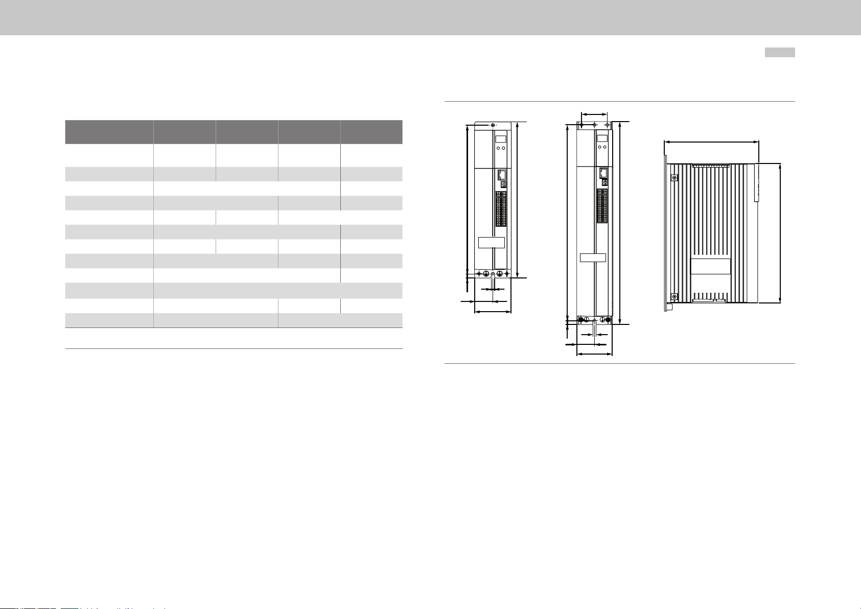
3. 2.1 Dimensions of the devices
MSDSingle-Axis Servo Drive Compact Operation Manual
14
Size C2 C3 C4 C5
MSD Single-Axis Servo
Drive Compact
Weight 1.0 kg (2.2 lb) 1.5 kg (3.3 lb) 2.8 kg (6.2 lb) 5.9 kg (13 lb)
B (width) 55 ( 2.17 ) 90 (3.54)
1)
H (height)
1)
T (depth)
A 27.5 (1. 0 8) 20 (0.79)
A1 - - 40 (1.57) 50 (1. 97)
C 225 (8.86) 30 5 (12.01) 313 (12.32)
C1 5 (0.20) 6 (0. 24)
DØ 4. 8 (0.19)
H1 235 (9.25) 315 (12.40) 324 (12 .76)
Screws 2 x M4 4 x M4
All dimensions in mm (in)
1) without terminals/connections
Table 3.2 MSD Single-A xis Ser vo Drive Compact dimensions - see Figure 3.1 and Figure 3.2
G394-030
G394-020
210 (8.27) 29 0 (11.42 ) 29 1 (11.47)
142 (5.59) 18 9 ( 7. 4 4) 235.5 (9.27)
G394-059
G394-035
G394-080
G394-065
G394-120
G3 9 4 -16 0
C
H1
C
C2 + C3
C4
D
A
B
C1
A
B
Figure 3.1 Dimensional drawing C2, C3, C4
T
H
H1
C2 + C3 + C4
D
Page 15
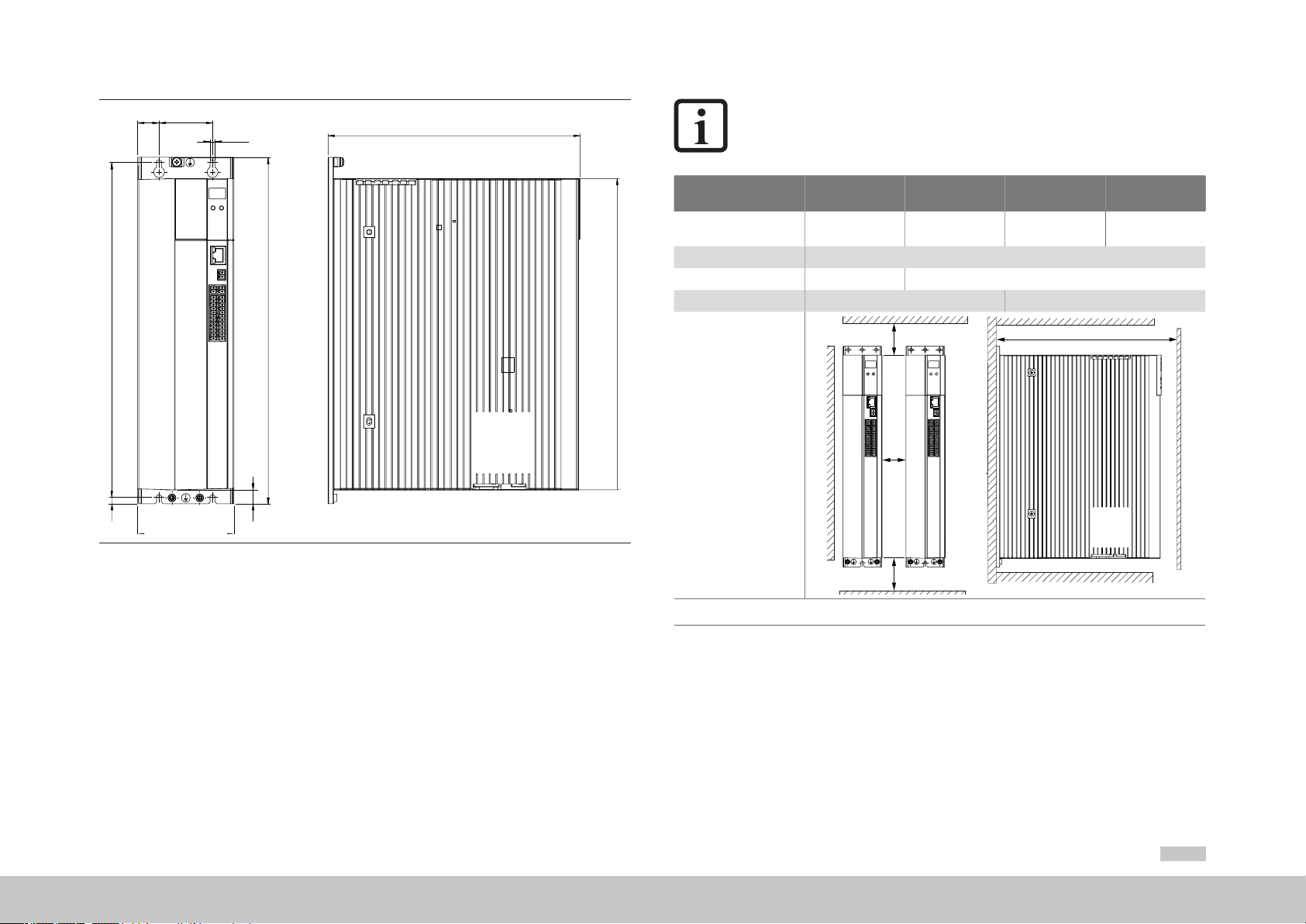
NOTE
A1A
C
D
T
If MSD Single-Axis Servo Drive Compact devices are attached to other
product ranges, corresponding measures must be taken to prevent the
devices affecting each other thermally.
Size C2 C3 C4 C5
H1
MSD Single-Axis Servo
Drive Compact
E Direct butt mounting
1)
F
1)
G
H
Drawing:
Dimensions in mm (in)
G394-030
G394-020
≥100 (3.94) ≥150 ( 5.9 0 )
≥235 (9.25) ≥2 8 0 (11. 0 2)
G394-059
G394-035
G394-080
G394-065
F
E
G394-120
G3 9 4 -16 0
G
C1
Figure 3.2 Dimensional drawing C5
B
H2
F
3.2.2 Mounting clearances
The minimum distances specied in the table apply for devices of the same power.
1) The bend radius of the c onnecti ng cables must be take n into acco unt
Table 3.3 MSD Single-A xis Servo Drive Compact mounting clearances
When butt mounting devices with different drive power you should arrange the devices
according to their power (e.g., viewed from the left, C5-C4-C3-C2). This arrangement
will minimise the thermal interaction.
moog
ID no.:CA97555-001 Date:04/2018
MSDSingle-Axis Servo Drive Compact Operation Manual
15
Page 16

moog
ID no.:CA97555-001 Date:04/2018
MSDSingle-Axis Servo Drive Compact Operation Manual
16
Page 17
4 Electrical installation
4.1 Notes for installation
DANGER Risk of injury due to electrical power!
• Carelessness will result in serious injuries or death.
Never wire or disconnect electrical connections while these are live! Always disconnect the power
before working on the device. Dangerously high voltages of ≥50V may still be present 10min.
after the power is cut (capacitor charge). So check that electrical power is not present!
Work on the device must only be carried out after the DC link voltage has dropped below a
residual voltage of 50V (indicated by monitoring LED H1 and to be measured on terminals X1/Land L+).
A dangerous voltage may be present at the device, even if the device does not emit any visual
or audible signals/indications (e.g. with mains voltage applied to terminal X3 and missing control
supply +24 V on X2)!
The following general guidelines apply for the installation of Servo Drives:
y Compliance with the EMC product standard
− Commissioning (i.e. starting intended operation) is only permitted on compliance with the
EMC product standard IEC/EN61800-3. The installer/operator of a machine and/or system
must provide proof of compliance with the protection targets stipulated in the standard.
y Cable type
− Use only shielded mains, motor and signal lines with double copper braiding with 60 to 70%
coverage.
y Cable laying
− Route mains, motor and signal cables separated from one another. If possible, keep a
distance of at least 0.2 m (0.66 ft), otherwise use separators. They should not run in parallel.
If crossovers are unavoidable, they should wherever possible be configured perpendicular (at
a 90° angle).
− Always route the motor cable without interruptions and the shortest way out of the control
cabinet. When using a motor contactor for example, the component should be directly
mounted to the servo drive and the shielding of the motor cable should not be stripped back
too far.
− If possible signal lines should only enter from one side into the switch cabinet.
− Lines of the same electric circuit must be twisted.
− Avoid unnecessary cable lengths and loops.
Earthing measures
y
− Earthing measures of relevance for the servo drive are described in section “4.6 Protective
earth conductor connection”.
y Shielding measures
− Do not strip the cable shields back too far, and lay them with large area connections both on
the component and on the backing plate or on the PE rail (main earth) for the backing plate.
y External components
− Place larger loads near the supply.
− Contactors, relays, solenoid valves (switched inductances) must be wired with suppressors.
The wiring must be directly connected to the respective coil.
− Any switched inductance should be at least 0.2 m (0.66 ft) away from the process controlled
assemblies.
y Additional information can be found in the corresponding connection description.
If you require further detailed information on installation you should consult the Moog Helpline
(see “Commissioning” on page 45).
moog
ID no.:CA97555-001 Date:04/2018
MSDSingle-Axis Servo Drive Compact Operation Manual
17
Page 18
moog
ID no.:CA97555-001 Date:04/2018
MSDSingle-Axis Servo Drive Compact Operation Manual
18
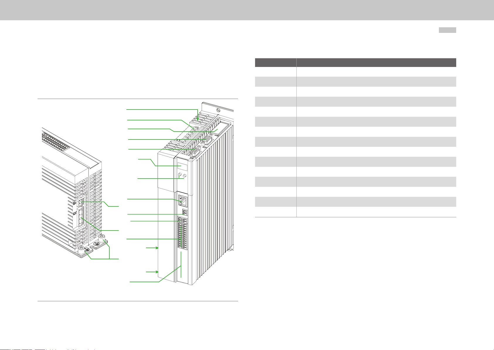
4.2 Layout
The following shows the layout with the corresponding positions of plugs and terminals.
For better orientation we have identified the designations of plugs and terminals with an
abbreviation.
H1
X1
X8
X7
X6
D1, D2
T1, T2
X9
X2
X5
X13
X3
X4
TS-Software
Number Designation
D1, D2 7-segment display
H1 DC link voltage indicator LED (only size C2 to C4)
OP1 Installation space for option 1 (Communication)
T1, T2 Button
X1 Power connections (only size C2 to C4)
X2 Connection for control supply U
X3 AC power connection
PE (bottom) Device protective earth conductor connection
X4 Control terminals
X5 Motor temperature monitoring
X6 Resolver connection
X7 Connection for high-resolution encoder
X8 Option 2 (Technology)
X9 Ethernet interface
X13 Connection for motor brake
Table 4.1 Key to layout MSD Single-Axis Servo Drive Compact C2 to C4
V
PE
TS-Hardware
OP1
Figure 4.1 Layout MSD Single-Axis Servo Drive Compact C2 to C4
Page 19
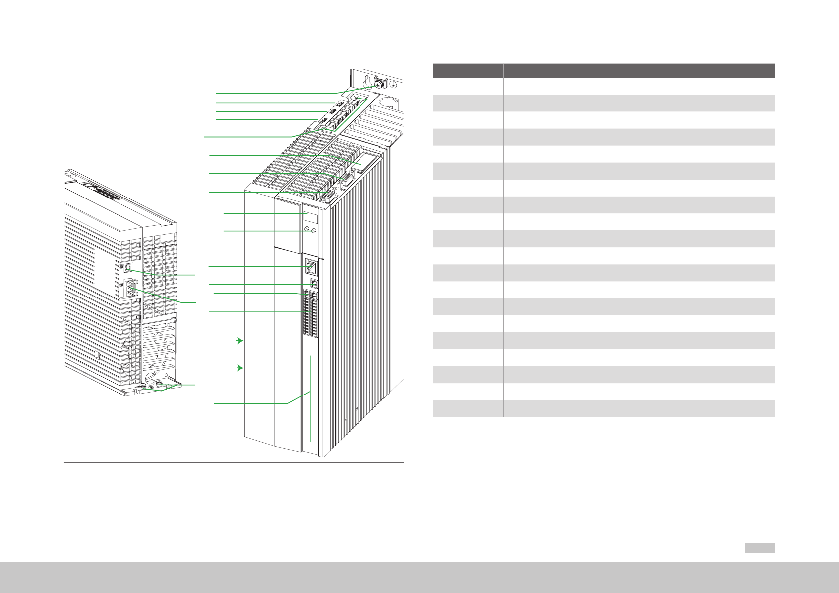
PE
X1.c
X1.b
X1.a
S
Number Designation
D1, D2 7-segment display
OP1 Installation space for option 1 (Communication)
T1, T2 Button
PE (top) Motor PE connection
X8
X7
X6
D1, D2
T1, T2
X9
X2
X5
X13
X3
X4
T. Software
T. Hardware
PE
OP1
X1.a Motor connection (only size C5)
X1.b Measurement of DC link voltage (only size C5)
X1.c Connection for braking resistor (only size C5)
X2 Connection for control supply U
V
X3 AC power connection
PE (bottom) Device protective earth conductor connection
X4 Control terminals
X5 Motor temperature monitoring
X6 Resolver connection
X7 Connection for high-resolution encoder
X8 Option 2 (Technology)
X9 Ethernet interface
X13 Connection for motor brake
S Receptacle for shield plate (see “Detail1: Motor cable C5” on page 23)
T. Software Software rating plate
T. Hardware Hardware rating plate
Table 4.2 Key to layout MSD Single-Axis Servo Drive Compact C5
Figure 4.2 Layout MSD Single-Axis Servo Drive Compact C5
moog
ID no.:CA97555-001 Date:04/2018
MSDSingle-Axis Servo Drive Compact Operation Manual
19
Page 20
moog
Top view
Bottom view
ID no.:CA97555-001 Date:04/2018
MSDSingle-Axis Servo Drive Compact Operation Manual
20
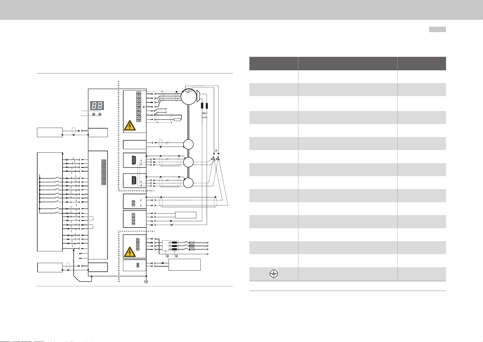
4.3 Connection diagram C2 to C4
1)
Option 2
54321
15 14 13 12 11
10 9876
4321
9876
GND
OSD03
GND
U
V
W
Brake (+)
Brake (-)
Mains 3-phase
FN
DC-link
Braking
resistor
n
n
6
+24 V DC supply for
brake
+24 V DC supply for
control electronic (U
L-
L+
RB
1+
10
9
1-
5
1+
9
1-
+/1
-/2
4
V+
3
2
1
PE
L3
L2
L1
+
+
-
–
D1, D2
T1, T2
Service
interface
Control
Analog set point 1
Analog set point 2
+24 V DC against
E/A-GND
Diagnosis
Relay
Digital0
Digital1
Digital2
E/A-GND
Communication
field buses
STO
Ethernet
3
ISA00+
4
ISA00-
5
ISA01+
6
ISA01-
ISD00
15
ISD01
16
ISD02
17
ISD03
18
ISD04
19
ISD05
20
ISD0621
10
ENPO (STO)
22
ISDSH (STO)
12
RSH
11
23
Relay
24
OSD04
7
OSD00
8
OSD01
9
OSD02
1
DGND
2,14
+24 V (U
13
DGND
Option 1
X9
X4
Front
)
H
1)
Figure 4.3 Connection diagram C2 to C4
X1
Danger!
X8
X7
X6
X5
X13
X3
Danger!
X2
Motor
3
~
Encoder
Resolver
K1
Number Designation Details
D1, D2 7-segment display Page 48
T1, T2 Button Page 48
X1
Connection for motor, braking resistor
and measurement of DC link voltage
Page 38
X2 Connection for control supply Page 27
X3 Connection for AC power supply Page 29
X4 Control terminals Page 31
(-)(+)
X5 Connection for motor temperature monitoring
X6 Connection for resolver
1)
X7 Connection for high-resolution encoder
1)
Page 37
Page 35
1)
Page 36
Option 1 Communication Page 33
PE PE connection Page 25
X8 (Option 2) Technology Page 33
X9 Ethernet interface Page 33
L3
L2
L1
PE
V)
X13 Connection for motor brake
1) Screen connections via separate shield plates
Connection for housing PE conductor
Page 32
Page 23
Page 25
1) NOTE: The temperature sensor for the motor winding can be connected either via the encoder cables (X6 or X7) or to terminal X5.
Table 4.3 Key to connection diagram C2 to C4
Page 21
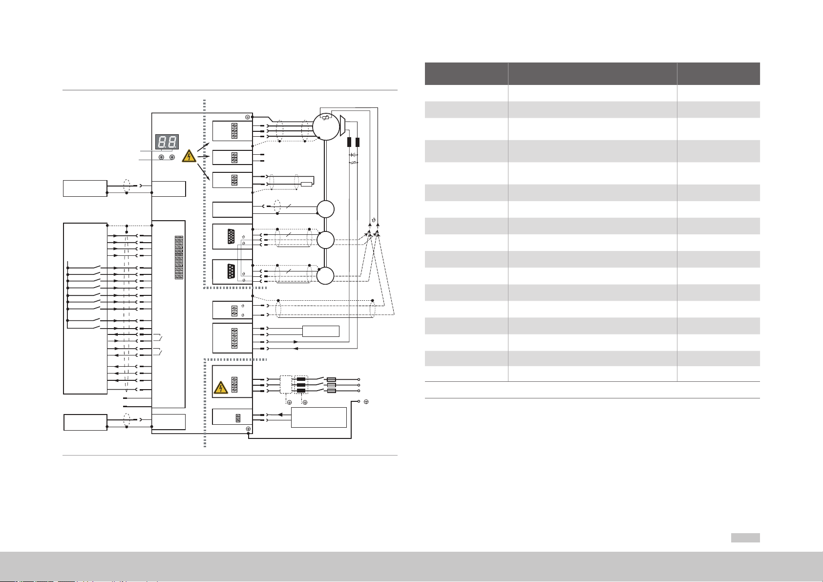
4.4 Connection diagram C5
Top view
U
V
1)
1)
Option 2
54321
15 14 13 12 11
10 9876
4321
9876
1)
GND
OSD03
GND
W
L-
L+
L+
RB
1+
10
9
1-
5
1+
9
1-
+/1
-/2
4
V+
3
2
1
L3
L2
L1
+
+
-
–
Service
interface
Control
Analog set point 1
Analog set point 2
+24 V DC against
E/A-GND
Diagnosis
Relay
Digital0
Digital1
Digital2
E/A-GND
Communication
field buses
STO
D1, D2
T1, T2
Ethernet
1)
3
ISA00+
4
ISA00-
5
ISA01+
6
ISA01-
ISD00
15
ISD01
16
ISD02
17
ISD03
18
ISD04
19
ISD05
20
ISD0621
10
ENPO (STO)
22
ISDSH (STO)
12
RSH
11
23
Relay
24
OSD04
7
OSD00
8
OSD01
9
OSD02
1
DGND
2,14
+24 V (U
13
DGND
Option 1
Danger
X1.b
X1.a
X9
X1.c
X8
X4
X7
X6
X5
Front
X13
X3
Danger
)
H
X2
DC-link
Brake (+)
Brake (-)
Braking
resistor
n
n
6
Mains 3-phase
FN
+24 V DC supply for
control electronic (U
Motor
3
~
Encoder
Resolver
+24 V DC supply for
brake
K1
Number Designation Details
D1, D2 7-segment display Page 48
T1, T2 Button Page 48
X1.a Motor connection Page 37
X1.b Measurement of DC link voltage -
X1.c Connection for braking resistor Page 37
X2 Connection for control supply Page 27
X3 Connection for AC power supply Page 29
(-)(+)
X4 Control terminals Page 31
X5 Connection for motor temperature monitoring
X6 Connection for resolver
1)
X7 Connection for high-resolution encoder
1)
Page 37
Page 35
1)
Page 36
Option 1 Communication Page 33
PE Connection for PE conductor Page 25
X8 (Option 2) Technology Page 33
X9 Ethernet interface Page 33
X13 Connection for motor brake
L3
L2
L1
1) NOTE: The temperature sensor for the motor winding can be connected either via the encoder cables (X6 or X7) or to terminal X5.
1) Screen connections via separate shield plates
Page 32
Page 23
Table 4.4 Key to connection diagram
V)
Bottom view
Figure 4.4 Connection diagram MSD Single-Axis Servo Drive Compact C5
moog
ID no.:CA97555-001 Date:04/2018
MSDSingle-Axis Servo Drive Compact Operation Manual
21
Page 22
moog
ID no.:CA97555-001 Date:04/2018
4.5 Effective EMC installation
MSDSingle-Axis Servo Drive Compact Operation Manual
22
4.5.1 Interference immunity of Servo Drives
NOTE
This is a restricted availability product in accordance with IEC/EN 61800-3.
This product may cause radio interference in domestic environments; in such
cases the operator may need to take appropriate countermeasures.
External radio frequency interference suppression filters (CB09937-001 to CB09940
001, CB09942-00, for C5 provisional CA71185-001) are available for the Servo Drives.
With the measurement method specified and the exte nal mains filte , these Servo
Drives conform to the EMC product standard IEC/EN 61800-3 for "First environment"
(residential C2) and "Second environment" (industrial C3).
4.5.2 Specimen setup
The specimen setup presented on the following pages is intended to illustrate the key
measures necessary to ensure an effective EMC installation.
NOTE
The specimen setup merely presents a recommendation, and does not
automatically guarantee compliance with applicable EMC directives.
The installer/operator of a machine and/or system must provide proof of
compliance with the protection targets stipulated in the standard.
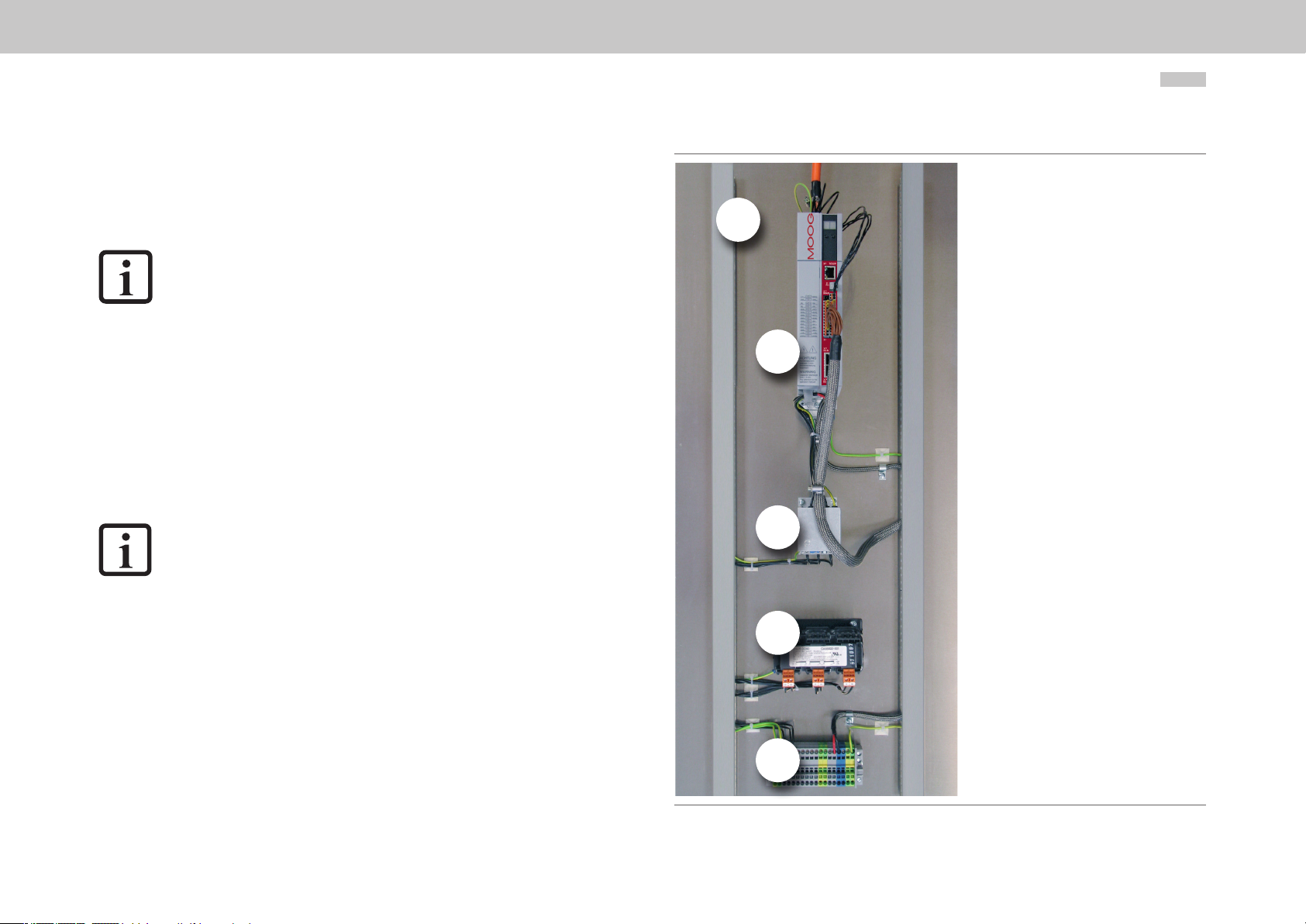
Overview
A
Detail 1
Detail 2
B
Detail 3
Detail 4
C
D
Figure 4.5 presents an overview of the minimum components required:
Backing plate with cable ducts
A.
B.
MSD Single-Axis Servo Drive Compact
Mains filter
C.
D.
Mains choke
E.
Distributor rail for AC power supply and control supply (+24VDC)
The layout and cabling are based on the requirements in section4.1 The numbered red
arrows refer to four very important detailed notes presented on the following pages.
E
Figure 4.5 Specimen setup - Overview
Page 23

Detail1: Motor cable
Make sure that on devices C2 to C4 the motor connection is connected to terminal (X1)
and on devices C5 to terminal (X1a, X1b, X1c):
y Fasten the shield connection plate supplied (shield plate for C2 to C4 see Figure 4.6, shield plate
for C5 see Figure 4.7) to the top of the device. Ensure the plate is in contact over a large area
with the heat sink on the MSD Single-Axis Servo Drive Compact and with the backing plate. Use
a serrated washer.
Figure 4.6 Shield plate C2 to C4 Figure 4.7 Shield plate C5
y Strip the shielding of the motor cable back only as short as absolutely necessary.
y Connect the motor cable shield over a large area to the shield connection plate using the clamp
supplied.
X1a
X1b
X1c
X1
Figure 4.8 Detail1: Motor cable C2 to C4 Figure 4.9 Detail1: Motor cable C5
NOTE
Ready made motor cables are available for Moog Servo Motors. For details
refer to the MSD Ordering Catalog or to the Servo Motors Ordering Catalog.
moog
ID no.:CA97555-001 Date:04/2018
MSDSingle-Axis Servo Drive Compact Operation Manual
23
Page 24

moog
ID no.:CA97555-001 Date:04/2018
MSDSingle-Axis Servo Drive Compact Operation Manual
24
Detail2: Control supply (+24VDC)
At the connection for the control voltage (X2) pay attention to:
y Secure the second of the two shield connection plates supplied to the mount on the bottom of
the unit using the screw. Ensure the plate is in contact over a large area with the heat sink on the
MSD Single-Axis Servo Drive Compact and with the backing plate. Use a serrated washer.
y Pull a shielding sleeve over the control supply cable and strip it back only as short as necessary
before the control supply connection (X2).
y Connect the shielding sleeve on the control supply cable with a large area connection to the
shield connection plate using the clamp supplied.
X2
Detail3: Mains filter and mains connection
At the output of the mains filter and the AC mains connection X3):
y Connect the litz wire on the output of the mains filter directly to the AC mains connection (X3) on
the MSD Single-Axis Servo Drive Compact. The litz wires must not be extended, so the mains
filter should be installed correspondingly close to the MSD Single-Axis Servo Drive Compact. But
be sure to maintain the necessary minimum clearance (see “Table 3.3 MSD Single-Axis Ser
Drive Compact mounting clearances”).
y Fix the litz wire to the shield connection plate using a cable tie as necessary.
y The leakage current of the MSD Single-Axis Servo Drive Compact is >3.5mA. So:
− Connect the protective earth conductor from the output of the mains filter to conne tion (X3)
on the MSD Single-Axis Servo Drive Compact C2 to B4 or to the housing of the
MSD Single-Axis Servo Drive Compact C5 and
− One of the PE connections on the heat sink on the MSD Single-Axis Servo Drive Compact
using a cable of at least the same cross-section to the main earth for the distributor rail.
X3
vo
Figure 4.10 Specimen setup - Detail 2: Control supply
Figure 4.11 Specimen setup - Detail3: Mains lter and mains connection
Page 25

Detail4: Control cables
At the control terminals (X4) of the MSD Single-Axis Servo Drive Compact:
y Strip the shielding of the control cables back only as short as absolutely necessary.
y Connect the shield on the control cables with a large area connection to the shield connection
tab on the mains filter using the clamp supplied If this is not possible, connect the control cable
shield directly to the backing plate with a large area connection directly adjacent to the
MSD Single-Axis Servo Drive Compact.
X4
4.6 Protective earth conductor connection
Step Action
Earth each of the Servo Drives!
Connect the terminal in a star configuration
1.
and with a large area connection to the PE
bar (main earth) in the control cabinet.
Also connect the PE conductor terminals on all other
components, such as mains choke, filte , etc. in a
star configuration and with a large a ea
2.
connection to the PE bar (main earth) in the control
cabinet.
PE mains connection
according to IEC/EN 61800-5-1
For the PE connection the following
applies (as leakage current >3.5mA):
Use protective earth conductors with the
same cross-section as the mains power
cables, though at least 10mm
²
Also comply with local and national
regulations and conditions.
(0.02in²).
Figure 4.12 Specimen setup - Detail4: Control cables
moog
ID no.:CA97555-001 Date:04/2018
U1
V2
U2
V1
U1
V2
U2
W1
W2
W1
V1
W2
PE
Figure 4.13 Star configuration layout for the PE conducto
MSDSingle-Axis Servo Drive Compact Operation Manual
U1
V2
U2
W1
V1
W2
25
Page 26

PE GNDµP
DGND
complexe
not linear
impedance
RC link Polyswitch
GNDµP
GNDµP
GNDµP
X4/15
ISD00
ISD01
I
LIM
X4/21
ISD06
I
LIM
X4/10
ENPO
I
LIM
X4/22
ISDSH
I
LIM
X4/7
OSD00
X4/3
ISA00+
Motor PTC
X4/4
ISA00-
ISD02
ISD03
ISD04
ISD05
A/D
A/D
ISA01+
X4/5
X4/6
ISA01-
X4/14
GNDµP
GNDµP
GNDµP
GNDµP
GNDµP
DGND
DGND
DGND
DGND
DGND
DGND
DGND
DGND
X4/2
ϑ
F1
ϑ
F2
X4/13
DGND
X4/1
ϑ
F3
V
µP
V
µP
V
µP
V
µP
µP
X4/8
OSD01
OSD03
Motor brake
GND
X4/9
OSD02
X5/ϑ +
X5/ϑ −
RSH
X13/2
X13/1
X4/12
X4/11
OSD04
X4/23
X4/24
Ethernet
X9
Resolver
X6
Encoder
X7
PE
U
V
U
V
X2/+
X2/-
U
H
Control
supply
24 V DC
24 V DC
Supply
Brake
GND
X13/3
X13/4
moog
ID no.:CA97555-001 Date:04/2018
4.7 Electrical isolation concept
The control electronics, with their logic (µP), the encoder terminals and the inputs and
outputs, are electrically isolated from the power section (power supply/DC link). All
control terminals are designed as safety extra-low voltage/protective extra-low voltage
(SELV/PELV) circuits and must only be operated with such SELV/PELV voltages, as per
the relevant specification. This p ovides reliable protection against electric shock on the
control side.
A separate control supply, compliant with the requirements of a SELV/PELV, is therefore
needed.
The overview opposite shows the potential references for the individual connections in
detail.
This concept also delivers higher operational safety and reliability of the servo drive.
MSDSingle-Axis Servo Drive Compact Operation Manual
26
Figure 4.14 Electrical isolation concept MSD Single-Axis Servo Drive Compact
SELV = Safety Extra Low Voltage
PELV = Protective Extra Low Voltage
Page 27

4.8 Connection of the supply voltages
X3
L1
X3
L1
Device 1 (e.g. C2) Device 2 (e.g. C2)
The supply of power to the MSD Single-Axis Servo Drive Compact is separate for the
control and power sections. The control supply should always be connected firs , so
that the device parameters can be set with Moog
device set to the correct supply for the power section.
CAUTION! Damage to the device due to incorrect operation!
• Carelessness can cause damage to the device.
Only when the mains voltage has been pre-set in the device firmware and the device has been
restarted (if the mains voltage or switching frequency has been changed) may the mains power
supply for the supply for the power section be activated.
4.8.1 Connection of control supply (+24VDC)
DriveADministrAtor5 and, above all, the
NOTE
Suitable measures must generally be applied to provide adequate cable
protection.
DANGER Risk of injury due to electrical power!
• Carelessness will result in serious injuries or death.
When the mains voltage is switched on at terminal X3 and there is no control supply (+24V DC at
X2), a dangerous voltage is present on the device with no visual signal on the display or acoustic
indication by fan noise. If visible in the installed state, LED H1 (see Figure 4.1) indicates whether
voltage is present on the device. Even if H1 is completely off, X1 must be checked to ensure no
electrical power is present.
NOTE
The start-up current for the supply voltage for the C2 to C5 may be two to
three times the operation current.
X2
+ + +
Figure 4.15 Connection of control supply MSD Single-Axis Servo Drive Compact
maximum 10 A gG
24 V DC ±10 %
external power
supply
next servo drive
Control supply (Specication)
= +24VDC ±10%, stabilised and filtered
• U
V
• I
= 2A (C2 to C5)
Control
supply
Table 4.5 Specification of control supply MSD Single-Axis Servo Drive Compact
X2/+
X2/-
moog
V
• Internal polarity reversal protection
• The power supply unit used must have a safe and reliable isolation against
the mains system acc. to EN50178 or IEC/EN61800-5-1
ID no.:CA97555-001 Date:04/2018
X2
MSDSingle-Axis Servo Drive Compact Operation Manual
27
Page 28

moog
ID no.:CA97555-001 Date:04/2018
MSDSingle-Axis Servo Drive Compact Operation Manual
28
4.8.2 Connection of mains supply
Procedure:
Step Action Comment
Specify the cable cross-section depending on the maxi-
1.
mum current and ambient temperature.
Wire the servo drive with the mains filte *), maximum cable
2.
length 0.3 m (1.0 ft) (with non-shielded cable)!
Wire the mains choke
3.
(if installed)
Install a mains isolating device K1
4.
(power circuit breaker, contactor, etc.).
Use mains fuses
(duty class gG) to isolate all poles of the servo drive from
5.
the mains supply.
*) optional
DANGER! Risk of injury due to electrical power!
• Carelessness will result in serious injuries or death.
Never wire or disconnect electrical connections while these are live! Always disconnect the power
before working on the device. Dangerously high voltages of ≥50V may still be present 10min.
after the power is cut (capacitor charge). So check that electrical power is not present!
CAUTION!
1) residual current protective device
2) residual current monitor
Risk or injury or damage to the device due to incorrect
earth leakage circuit breaker!
• Carelessness may result in injuries or damage.
If local regulations require the installation of an earth leakage circuit breaker, the following
applies: In case of a fault the servo drive is able to generate DC leakage currents without zero
crossing. Servo Drives therefore must only be operated with (RCDs) 1) type B for AC fault currents,
pulsating or smooth DC fault currents, which are suitable for servo drive operation, see
IEC60755. RCMs 2) can also be used for monitoring purposes.
*)
Cable cross-section according to local
regulations and conditions.
Reduces the distortion (THD) in the system
and prolongs the life of the servo drive.
Do not switch on the power!
For compliance with equipment safety
requirements laid down in IEC/EN61800-
5-1
Note the following points:
Switching the mains power:
y In the event of excessively frequent switching the device protects itself by means of high-
resistance decoupling from the mains. After a rest phase of a few minutes the device is ready to
start once again.
TN and TT system: Operation is permitted if:
y In the case of single-phase devices for 1x230VAC the supply system conforms to the
maximum overvoltage category III as per IEC/EN61800-5-1.
y In the case of three-phase devices with phase conductor voltages 3x230VAC, 3x400VAC,
3x460VAC and 3x480VAC
y The star point of the supply system is earthed and
y The supply system conforms to the maximum overvoltage category III as per IEC/EN61800-5-1
at a system voltage (phase conductor → neutral point) of maximum 277V.
IT system: Operation is not permitted!
y In case of an earth fault the voltage is approx. twice as high. Clearances and creepages to
IEC/EN61800-5-1 are no longer maintained.
Connection of the servo drives via a mains choke is imperative:
y Where the servo drive is used in applications with disturbance variables corresponding to
environment class 3, as per IEC/EN 61000-2-4 and above (harsh industrial environment)
y In the case of single-phase mains supply
y For compliance with IEC/EN61800-3
For further information on permissible current loads, technical data and ambient
conditions please refer to the appendix.
NOTE
Please be aware that the MSD Single-Axis Servo Drive Compact is not
rated for environment class 3. Further measures are essential to achieve
this environment class! For further information please consult your project
engineer.
Page 29

C2 and C3
Mains
1-phase
C2 and C3
4.8.3 Connected load and mains fuse
Mains supply for C2 and C3 devices
2)
Specied mains
fuse, duty class
3)
gG [A]
Servo
Drive
Device rated power
With mains
choke (4% u
)
mains choke
K
1)
[kVA]
Without
Maximum cable cross-section
of the terminal [mm²]
Ferr. with
3)
insul
Ferr. w/o
insul
1x16 maximum
G394-030 1.3 1.6
2.5 2.5
(1-phase)
3x16 maximum
(3-phase)
G394-020 1.5 1.9 3x. 6 maximum
1x16 maximum
G394-059 2.6 3.2
2.5 2.5
(1-phase)
3x16 maximum
(3-phase)
G394-035 2.7 3.3 3x10 maximum
1x20 maximum
G394-080 3.5 4.3
4 4
(1 phase)
3x20 maximum
(3 phase)
G394-065 5.0 6.1 3x16 maximum
G394-120 8.1 10.5
4 6
3 x 32 maximum
G394-160 10.2 13.2 3 x 40 maximum
1) At 3x230VAC or 3x400VAC mains voltage and FT ≥ 8 kHz
The minimum cross-section of the mains power cable depends on the local regulations and conditions, as well as on the rated current of the servo drive.
2)
3) Ferr. with insul. = Ferrule with plastic insulation, Ferr. w/o insul. = Ferrule without plastic insulation
Table 4.6 Connected load and mains fuse
NOTE
Before commissioning, the value of the connected mains voltage must be
set on the servo drive (factory setting = 3x230VAC / 3x400VAC).
X2
+
Mains
Mains
3-phase
L1
L2
L3
K1F1
Figure 4.16 Connection C2 and C3 mains supply 3x230V (G394-030, G394-059) or 3x400V
(G394-020, G394-035) depending on device design
L1
N
Mains
ÿlter
choke
Mains
choke
K1F1
Mains
ÿlter
X3
X2
X3
L1
L2
L3
+
L1
L2
L3
moog
ID no.:CA97555-001 Date:04/2018
Figure 4.17 Connection C2 and C3 mains supply 1x230V) (G394-030, G394-059)
MSDSingle-Axis Servo Drive Compact Operation Manual
29
Page 30

moog
L1
L2
L3
Mains
3-phase
C4
C4
ID no.:CA97555-001 Date:04/2018
MSDSingle-Axis Servo Drive Compact Operation Manual
30
Mains supply for C4 devices
NOTE
Before commissioning, the value of the connected mains voltage must be
set on the servo drive (factory setting = 3x230VAC / 3x400VAC).
X2
X3
X2
+
L3
L2
L1
+
Mains
3-phase
L3
L2
L1
K1F1
Figure 4.18 Connection of C4 to mains supply 3x230V (G394-080) or 3x400V (G394-065)
depending on device design
Mains
1-phase
Mains
choke
Mains
ÿlter
Mains supply for C5 devices
NOTE:
Before commissioning, the value of the connected mains voltage must be
set on the servo drive (factory setting = 3x400VAC).
Mains
Mains
K1F1
Figure 4.20 Connection of C5 to mains supply 3x400V (G394-120, G394-160) depending on
device design
choke
ÿlter
X2
+
L3
L2
X3
L1
N
L1
K1F1
Figure 4.19 Connection of C4 to mains supply 1x230V (G394-080)
Mains
choke
Mains
ÿlter
X3
L3
L2
L1
CAUTION! Shutdown of the pre-charging!
To protect the servo drive from thermal overload, make sure that the pre-charging of the DC
link is not switched on for more than 2 minutes without the main contactor is active.
The pre-charging of the DC link is not designed for high power consumption during the
operation.
Ignoring of this rule may destroy the device!
Page 31

REL
REL
ISDSH
ISD06
ISD05
ISD04
ISD03
ISD02
ISD01
ISD00
+24V
DGND
RSH
RSH
ENPO
OSD02
OSD01
OSD00
ISA1-
ISA1+
ISA0-
ISA0+
+24V
DGND
X4
4.9 Control connections
4.9.1 Specification of cont ol connections
Step Action Comment
Check whether complete device settings are already
1.
available, i.e. whether the drive has already been
configured
If this is the case, a special control terminal assign-
2.
ment applies.
Please contact your project engineer to obtain the
terminal assignment!
3.
Choose a terminal assignment. Initial commissioning
Wire the control terminals with shielded cables.
4.
The following is imperative: STO request X4/22,
ENPO X4/10 and a start signal (with control via
terminal).
5.
6.
Keep all contacts open (inputs inactive).
Check all connections again! Continue with chapter “5 Commissioning”
Note the following points:
y Always wire the control terminals with shielded cables.
y Lay the control cables separately from the mains power and motor cables.
y A cable type with double copper braiding, with 60 to 70% coverage, must be used for all
shielded connections.
moog
ID no.:CA97555-001 Date:04/2018
Earth the cable shields over a large area at
both ends.
Rigid conductor sizes: 0.2 to 1.5 mm²
(0.0003 to 0.0023 in²)
Flexible conductor sizes:
- Ferrule without plastic sleeve:
0.2 to 1.5 mm² (0.0003 to 0.0023 in²)
- Ferrule with plastic sleeve:
0.2 to 0.75 mm² (0.0003 to 0.0012 in²)
Des. Term. Specication Electrical isolation
Analog inputs
= ±10VDC
• U
ISA0+
ISA0-
ISA1+
ISA1-
X4/3
X4/4
X4/5
X4/6
IN
• Resolution 12bits; R
approx.101kΩ
IN
• Terminal scan cycle in "IP mode" = 125µs, otherwise
= 1ms
• Tolerance: U±1% of the measuring range end value
no
Digital inputs
ISD00
ISD01
ISD02
ISD03
ISD04
ISD05
ISD06
X4/15
X4/16
X4/17
X4/18
X4/19
X4/20
X4/21
ENPO X4/10
• Frequency range <500Hz
• Terminal scan cycle in = 1ms
• Switching level Low/High: ≤4.8V / ≥18V
= +24VDC +20%
• U
IN max
• I
at +24VDC = typ. 3mA
IN
• Frequency range ≤500kHz
• Switching level Low/High: ≤4.8V / ≥18V
• U
= +24VDC +20%
IN max
• I
max at +24VDC = 10mA, RIN approx. 3kΩ
IN max
• Internal signal delay < 2 µs suitable as trigger input for
quickly saving actual position
• Disable restart inhibit (STO)
and enable power stage =
High level
• OSSD support
• 10ms
yes
yes
yes
24
23
22
21
20
19
18
17
16
15
14
13
• Switching level Low/High: ≤4.8V / ≥18V
• U
= +24VDC +20%
IN max
• I
at +24VDC = typ. 3mA
IN
Digital outputs
• No destruction in case of short-circuit (+24VDC ->
OSD00
OSD01
OSD02
X4/7
X4/8
X4/9
DGND), but device may briefly shut down
= 50mA, PLC-compatible
• I
max
• Terminal scan cycle in = 1ms
yes
• High-side driver
Table 4.7 Specification of control connections X4
MSDSingle-Axis Servo Drive Compact Operation Manual
12
11
10
9
8
7
6
5
4
3
2
1
31
Page 32

moog
I
I
REL
REL
ISDSH
ISD06
ISD05
ISD04
ISD03
ISD02
ISD01
ISD00
+24V
DGND
RSH
RSH
ENPO
OSD02
OSD01
OSD00
ISA1-
ISA1+
ISA0-
ISA0+
+24V
DGND
X4
X4/12
X4/11
X4/23
X4/24
ID no.:CA97555-001 Date:04/2018
MSDSingle-Axis Servo Drive Compact Operation Manual
32
Des. Term. Specication Electrical isolation
STO "Safe Torque Off"
• "Request STO" input = Low level
ISDSH
(STO)
X4/22
• OSSD support
• Switching level Low/High: ≤4.8V / ≥18V
• U
IN max
• I
at +24VDC = typ. 3mA
IN
Diagnostics STO, both cut-off channels
RSH
RSH
active, one NO contact with automatically
X4/11
resetting circuit-breaker (polyswitch)
X4/12
• 25V / 200mAAC, cosϕ = 1
• 30V / 200mADC, cosϕ = 1
Relay outputs
Relay, 1 NO contact
• 25V / 1.0AAC, cosϕ = 1 (AC1)
• 30V / 1.0ADC, cosϕ = 1 (DC1)
• Switching delay approx. 10ms
REL
X4/23
X4/24
• Cycle time 1 ms
Auxiliary voltage
• Auxiliary voltage output (U
control inputs
• U
= UV-∆U (∆U typically approx. 1.2V), no destruction
+24V
X4/2
X4/14
H
in case of short circuit (+24VDC -> DGND), but
device may briefly shut down
• I
= 80mA (per pin) with self-resetting circuit
max
breaker (polyswitch)
Digital ground
DGND
X4/1
Reference ground for +24VDC yes
X4/13
Table 4.7 Specification of control connections X4
= +24VDC +20%
) for feeding the digital
H
yes
yes
yes
4.9.2 Connection of motor brake X13
Connector X13 is intended for connection of a motor brake.
Des. Term. Connection Specication
GND
GND
V+
X13/2
X13/1
X13/3
X13/4
< 2.0 A
BR
Front
X13
OSD03
Motor
3
~
4
24 V DC ext.
V+
supply
3
GND
2
Brake (+)
1
GND
Brake (-)
• Short-circuit proof
• External control supply +24VDC
(I
= 2.1 A) required via X13/3 (GND) and X13/4
IN
(V+)
• U
= UV-∆U` (∆U` typically approx. 1.4 V)
BR
• To actuate a motor holding brake up to
IBR = 2.0A maximum
• Overcurrent causes cyclic shutdown
• Also usable as configurable digital outpu
> 2.0 A
BR
Front
X13
OSD03
Motor
3
~
4
24 V DC ext.
V+
supply
3
GND
2
24 V DC
1
GND
Brake (-)
Brake (+)
• Cable break monitor:
With the brake driver switched on, cable break
is detected at output currents <200mA.
The cable break monitoring can be disabled.
NOTE:
For brakes with higher current requirements (> 2.0 A), a relay must be
provided. The cable break monitoring on X13 is then no longer usable and
must be provided externally.
OSD03
24
12
23
11
22
10
21
9
20
8
19
7
18
6
17
5
16
4
15
3
14
2
13
1
Table 4.8 Specification of the terminal connections X13
Page 33

4.10 Specification, Ethernet interface
4.12 Option 2
The service and diagnostic interface X9 is designed as a TCP/IP Ethernet interface. It
is suitable for connection of a PC for commissioning, service and diagnostics and for
programming of the servo drive.
The following software can communicate with the servo drive via the Ethernet interface:
y Moog DriveADministrAtor5 for commissioning, service and diagnostics on the MSD Single-Axis
Servo Drive Compact
y
CoDeSys 3.x programming system for programming the MSD Single-Axis Servo Drive Compact
in the languages of IEC61131-3. For this purpose a servo drive licence is required.
Specification of interface
y Transfer rate 10/100 Mbits/s BASE
y Line protocol IEEE802.3 compliant
y Connection via standard commercially available crosslink cable, CAT5
4.11 Option 1
Depending on the MSD Single-Axis Servo Drive Compact variant, Option 1 is factoryconfigu ed with various options. Field bus options such as EtherCAT or SERCOS are
available.
You will find all available options in the MSD O dering Catalog. The user manuals for the
respective options provide detailed information on commissioning.
Option 2 can be factory-configu ed with various technology options. Additional or special
encoders can be evaluated here for example.
You will find all available options in the MSD O dering Catalog. The user manuals for the
respective options provide detailed information on commissioning.
moog
ID no.:CA97555-001 Date:04/2018
MSDSingle-Axis Servo Drive Compact Operation Manual
33
Page 34

moog
r
ID no.:CA97555-001 Date:04/2018
MSDSingle-Axis Servo Drive Compact Operation Manual
34
4.13 Encoder connection
All encoder connections are located on the top of the unit.
Encoder connection for synchronous motors
Please use the ready made motor and encoder cables from Moog to connect the
synchronous motors (see Servo Motors Ordering Catalog).
Assignment of servo
Compare the rating plates of the components. Make absolutely sure you are using the
correct components according to variant A, B or C!
7
X
X
(optional
6
1
X
drive motor-encoder connection
Variant
C
8
X
Variant
)
Variant
A
B
high-resolution encode
high-resolution encoder
NOTE:
Do not split the encoder cable, for example to route the signals via terminals in
the switch cabinet. The knurled screws on the D-Sub connector housing must
be tightly locked!
Motor (with installed encoder) Encoder cable
Variant A
Variant B
Variant C
Table 4.9 Variants of motors, encoder type and encoder cable
With resolver
without further options
Sin/Cos single-/multi-turn encoder
with SSI/EnDat interface
Sin/Cos single-/multi-turn encoder
with HIPERFACE® interface
C08335-013-yyy X6
CA58876-002-yyy X7
CA58877-002-yyy X7
Servo drive
connection
4.13.1 Ready made encoder cables
The specifications can only be assu ed on the usage of Moog system cables.
Encoder cab
Ready m ade cab
Resolver cable
Encoder cable SSI, EnDat CA58876
Encoder cable Hiperface
Encoderystem
Version
Cable l e (m)
C08335
® CA5 8877
013
002
002
- yyy
1)
Resolver
Figure 4.21 Motor/encoder cable assignment
1) yyy sta nd for length in meters; stan dard le ngth; Sta ndardlängen: 1 m (3.28 ft), 5 m (16.40 ft), 10 m (32.80 ft), 15 m (49 ft),
20 m (65 ft), 50 m (164 ft). Furthe r length o n reque st
Encoder cabl C08335-013-yyy
1)
Order code
Page 35

X6
Resolver
Technical data
C08335-013-yyy
1)
CA58876-002-yyy
G3, G5, G12.x
Encoder system Resolver
(Single-/multi-turn with
SSI/EnDat interface)
Drive-end assignment
(sub-D connector)
1 = S3
2 = S1
3 = S2
4 = n.c.
5 = PTC+
6 = R1
7 = R2
8 = S4
9 = PTC-
1 = A2 = A+
3 = VCC (+5 V)
4 = DATA+
5 = DATA6 = B8 = GND
11 = B+
12 = VCC (Sense)
13 = GND (Sense)
14 = CLK+
15 = CLK7, 9, 10 = n.c.
Suitable for energy
chains
yes
Minimum bending radius 90 mm (3.54 in) 100 mm (3.93 in) 90 mm (3.54 in)
Temperature range
-40 to +85 °C
(-40 to +185 °F)
-35 to +80 °C
(-31 to +176 °F)
Cable diameter approx. 8.8 mm (0.34 in)
Outer sheath material PUR
Resistance Oil, hydrolysis and microbe resistant (VDE0472)
Approvals
UL style 20233, +80 °C (+176 °F) - 300 V,
CSA-C22.2N.210-M90, +75 °C (+167 °F) - 300 V FT1
Table 4.10 Technical data encoder cable
1)
CA58877-002-yyy
(Single-/multi-turn with
HIPERFACE® interface)
1 = REFCOS
2 = +COS
3 = Us 7 – 12 V
4 = Data+ EIA485
5 = Data- EIA485
6 = REFSIN
7 = Bridge to PIN 12
8 = GND
11 = +SIN
12 = Bridge to PIN 7
9, 10, 13, 14, 15 = n.c.
-40 to +85 °C
(-40 to +185 °F)
G6, G6.x
4.13.2 Resolver connection X6
1)
A resolver is connected to slot X6 (9-pin D-Sub socket).
Figure X6/Pin
ResolverS3 differential input (reference to Pin X6-2)
1
Resolver S1 differential input (reference to Pin X6-1)
2
3
Resolver S2 differential input (reference to Pin X6-8)
4
Supply voltage 5 ... 12V, internally connected to X7/3
5
ϑ+ (PTC, KTY, Klixon) internally connected to X7/10
6
9876
543 21
1) Be sure to pay attention to the note headed "ATTENTION" in Table 4.14!
Ref+ analog excitation
7
Ref- analog excitation (ground reference point for pin6 and pin4)
8
Resolver S4 differential input (reference to Pin X6-3)
9
ϑ- (PTC, KTY, Klixon) internally connected to X7/9
Table 4.11 Pin assignment X6 resolver connection
Function
1)
1)
moog
ID no.:CA97555-001 Date:04/2018
MSDSingle-Axis Servo Drive Compact Operation Manual
35
Page 36

moog
X7
ID no.:CA97555-001 Date:04/2018
MSDSingle-Axis Servo Drive Compact Operation Manual
36
4.13.3 Connection for high-resolution encoder
The interface X7 enables evaluation of the following encoder types.
Figure Function
Sin/Cos encoder with zero pulse
e.g. Heidenhain ERN1381, ROD486
Heidenhain Sin/Cos encoder with EnDat interface
e.g. 13 bit single-turn encoder (ECN1313.EnDat01) and 25 bit multi-turn encoder
(EQN1325-EnDat01)
Heidenhain encoder with digital EnDat interface
Encoder/ SSI
Table 4.12 Suitable encoder types on X7
NOTE:
y The usage of encoders not included in the range supplied by Moog
y The maximum signal input frequency is 500kHz.
y Encoders with a power supply of 5V ±5% must have a separate sensor
Select the cable type specified by the motor or encoder manufactu er. During this
process bear in mind the following:
y Always used shielded cables. The shield is to be connected at both ends.
y Connect the differential track signals A/B, R or CLK, DATA to each other using twisted pairs.
y Do not split the encoder cable, for example to route the signals via terminals in the switch
cabinet.
Single- or multi-turn encoder
Sin/Cos encoder with SSI interface
e.g. 13 bit single-turn and 25 bit multi-turn encoder (ECN413-SSI, EQN425-SSI)
Sick-Stegmann Sin/Cos encoder with HIPERFACE® interface
Single- and multi-turn encoder, e.g. SRS50, SRM50
requires special approval by Moog.
cable connection. The encoder cable detects the actual supply voltage
at the encoder, thereby compensating for the voltage drop on the cable.
Only use of the sensor cable ensures that the encoder is supplied with the
correct voltage. The sensor cable must always be connected.
Sin/Cos
X7 Pin
Sin/Cos
and TTL
absolute value
encoder
SSI/EnDat
1 A- A- - REFCOS
2 A+ A+ - +COS
+5VDC ±5%, IOUT maximum=250mA (150mA for
3
4 R+ Data + Data + Data +
5 R- Data - Data - Data -
6 B- B- - REFSIN
7 - - - U
8 GND GND GND GND
9
10
11 B+ B+ - +SIN
12 Sense + Sense + Sense + U
13 Sense - Sense - Sense - -
14 - CLK+ CLK+ -
15 - CLK - CLK - -
1) Be sure to pay attention to the note headed "ATTENTION" in Table 4.14!
Table 4.13 Pin assignment of the X7 terminal connection
hardware versions 0..1), monitoring via sensor cable
ϑ- (PTC, KTY, Klixon) internally connected to X6/9
ϑ+ (PTC, KTY, Klixon) internally connected to X6/5
Absolute value
encoder EnDat
(digital)
Absolute value
encoder HIPER-
maximum 100mA
1)
1)
NOTE:
The encoder supply on X7/3 is short-circuit proof on both 5V and 11V
operation. The drive remains in operation enabling the generation of a
corresponding error message on evaluating the encoder signals.
FACE®
7 to 12V
(typ. 11V)
switch
S
switch
S
The sum of the currents tapped at X7/3
and X6/4 must not
exceed the specified
value!
After connecting
pin 7 to pin 12, a
voltage of 11.8 V is
set on X7, pin3!
Page 37

4.14 Motor connection
1.
2.
3.
Step Action Comment
Specify the cable cross-section depending on the
maximum current and ambient temperature.
Connect the shielded motor cable to terminals X1/
U, V, W and connect the motor to earth at .
Cable cross-section according to local
and country-specific regulations and
conditions
Connect the shield at both ends to
reduce
interference emissions.
CAUTION Damage to the device due to incorrect insulation of the motor winding!
• Carelessness can cause damage to the motor/device
The motor temperature sensor must, in relation to the motor winding, on connection to X5 be
provided with basic insulation, on connection to X6 or X7 with reinforced insulation
as per IEC/EN61800-5-1.
NOTE:
In the event of a short-circuit or earth fault in the motor cable, the power stage
is disabled and an error message is issued.
Wire the motor temperature sensor and activate
temperature evaluation using
Moog DriveADministrAtor. See also related note.
Connect the shield at both ends to
reduce interference emissions.
4.14.1 Motor temperature sensor
Connection
servo drive
X5 Temperature switch (Klixon), PTC Sensor with basic insulation
X6 Temperature switch (Klixon), PTC, KTY Sensor with reinforced insulation
X7 Temperature switch (Klixon), PTC, KTY Sensor with reinforced insulation
Table 4.14 Motor temperature sensor terminal configuratio
Type of sensor Insulation
moog
ID no.:CA97555-001 Date:04/2018
MSDSingle-Axis Servo Drive Compact Operation Manual
37
Page 38

moog
Front
Top view
Top view
ID no.:CA97555-001 Date:04/2018
MSDSingle-Axis Servo Drive Compact Operation Manual
38
4.14.2 Connection of the servo motors
For connection of the servomotor product range please use the ready made motor
cable.
U
X1
Danger!
X8
X7
X6
X5
X13
Option 2
GND
OSD03
GND
V
W
L-
L+
RB
1+
10
9
1-
5
1+
9
1-
+
-
4
V+
3
Brake (+)
2
Brake (-)
1
DC-link
n
n
6
Braking
resistor
24 V DC supply for
brake
Motor
3
Encoder
Resolver
~
Danger
(-)(+)
Front
Figure 4.22 Connection of motor C2 to C4 Figure 4.23 Connection of motor C5
U
V
W
X1.a
1)
L-
DC-link
L+
X1.b
L+
RB
X1.c
1)
2
Option
X8
X7
1+
10
54321
15 14 13 12 11
10 9876
9
1-
X6
X5
X13
5
1+
4321
9876
9
1-
1)
+/1
-/2
4
V+
3
GND
Brake (+)
2
OSD03
Brake (-)
1
GND
n
n
6
Braking
resistor
+24 V DC supply for
brake
Motor
3
Encoder
Resolver
~
Ready made motor cable
C08336 - xxx yyy
Ready made motor ca ble
Version
Cable length (m)
1) yyy sta nds for le ngth in m eters; sta ndard l ength: 1 m (3.28 ft), 5 m (16.40 ft), 10 m (32.80 ft), 15 m (49 ft), 20 m (65 f t), 50 m
(164 ft). Weitere Fu rthe r length on reque st
(-)(+)
Motor cable C08336-xxx-yyy Order code
1)
DC link: Connection C2 to C4 X1/L+, L- Connection C5 X1.b/ L+, L-
CAUTION! Damage to the device due to DC link coupling!
• Carelessness can cause damage to the device
Coupling together the DC links on several device devices is not allowed.
Page 39

Technical data
Technical data C08336-xxx-yyy
Continuous rated
current
Cable cross-section
Temperature range
4 x 1,5mm² + 2 x 1mm²
(4 x 0.0024 in² + 2 x 0.0016 in²)
-40bis +125°C
(-40 to +275 °F)
1),2)
CB05708-xxx-yyy
10A TBD 44A 61A 82A
4 x 4mm² + 2 x 1,5mm²
(4 x 0.0062 in² + 2 x 0.0023 in²)
TBD
1),2)
CA44958-xxx-yyy
4 x 6mm² + 2 x 1,5mm²
(4 x 0.0093 in² + 2 x 0.0023 in²)
-50bis +90°C
(-58 to +194 °F)
Connector pin Wiring Connector pin Wiring Connector pin Wiring Connector pin Wiring Connector pin Wiring
2 U 2 U U U U U U U
4 VV 4 VV V VV V VV V VV
1 WWW 1 WWW W WWW W WWW W WWW
Wiring
PE yellow / green PE yellow / green PE yellow / green PE yellow / green PE yellow / green
5 Brake + / white 5 Brake + / white + Brake - / white + Brake + / white + Brake + / white
6 Brake - / black 6 Brake - / black - Brake - / black - Brake - / black - Brake - / black
Connector
housing
Monitor
Connector
housing
Monitor
Connector
housing
Connector type Size 1 Size 1 Size 1
1) yyy sta nds for le ngth in m eters; sta ndard l ength: 1 m (3.28 ft), 5 m (16.40 ft), 10 m (32.80 ft), 15 m (49 ft), 20 m (65 f t), 50 m (164 ft). Further len gth on request
2) xxx-001 for standard conguration option, further options on request
Table 4.15 Technical data motor cab
1),2)
Monitor
CB00076-xxx-yyy
1),2)
4 x 10mm² + 2 x 1,5mm²
(4 x 0.00155 in² + 2 x 0.0023 in²)
TBD TBD
Connector
housing
Monitor
Size 1 Size 1
CA98676-xxx-yyy
1),2)
4 x 16mm² + 2 x 1,5mm²
(4 x 0.0248 in² + 2 x 0.0023 in²)
Connector
housing
Monitor
NOTE:
Cores 5 and 6 (PTC) are required only for motors in which the motor PTC
cannot be connected via the encoder cable. In the case of servomotors with
resolver, the PTC is connected via the resolver cable.
moog
ID no.:CA97555-001 Date:04/2018
MSDSingle-Axis Servo Drive Compact Operation Manual
39
Page 40

moog
ID no.:CA97555-001 Date:04/2018
MSDSingle-Axis Servo Drive Compact Operation Manual
40
4.14.3 Switching in the motor cable
CAUTION! Damage to the device due to switching in the motor cable!
• Carelessness can cause damage to the device
Switching in the motor cable must take place with the power cut and the power stage disabled,
as otherwise problems such as burned contactor contacts or power stage damage may occur.
To ensure unpowered switch-on, you must make sure that the contacts of the motor
contactor are closed before the servo drive power stage is enabled. At the moment the
contactor is switched off it is necessary for the contact to remain closed until the servo
drive power stage is shut down and the motor current is 0. This is done by inserting
appropriate safety times for the switching of the motor contactor in the control sequence
of your machine.
NOTE:
Despite these measures, the possibility cannot be ruled out that the servo
drive may malfunction during switching in the motor cable.
4.15 Brake chopper connection
In regenerative operation, e.g. when braking the drive, the motor feeds energy back to
the servo drive. This increases the voltage in the DC link. If the voltage exceeds a
threshold value, the internal braking transistor is activated and the r
converted into heat by means of a braking resistor.
4.15.1 Protection in case of brake chopper fault
WARNING! Risk of injury due to hot surfaces caused by a faulty brake chopper!
• Carelessness may result in serious burns or damage.
If the brake chopper is overloaded the internal brake chopper transistor may be switched on continuously, which will result in the overheating of the device and the braking resistor. Temperatures
of up to +250 (+482 °F) may be reached. To prevent more serious damage we recommend the
activation of the following software function:
You can activate this function by assigning BC_FAIL(56) to any digital output
(Moog
DriveADministrAtor5 ►Subject area "I/O configuration" ►Digital outputs ►OSD00 to
OSD02). In the event of a fault the selected output then switches from 24 V to 0V.
This signal ensures that the servo drive is safely disconnected from the mains supply.
For detailed information on setting parameters refer to the "MSD Device Help".
4.15.2 Design with integrated braking resistor (C3+4+5)
For Servo Drives with an integrated braking resistor (model G394-xxx-xxx-xx2/xx4)
only the peak braking power is stated in the appendix. The permissible continuous
braking power must be calculated. It depends on the effective utilisation of the servo
drive in the corresponding application.
egenerated power is
The servo drive is thermally designed in such a way that no energy input by the internal
braking resistor is permitted during continuous operation at rated curr
ent and at
maximum ambient temperature.
Consequently, a servo drive design featuring an integrated braking resistor only makes
sense when the effective servo d
rive utilisation is ≤80% or the braking resistor is
designed for one-off emergency stop. In the event of an emergency stop, only the
thermal capacity of the braking resistor can be used for a one-off braking action. The
permissible energy W
can be taken from the following table.
IBr
Page 41

dti
T
I
T
eff
∫
=
0
2
1
dti
T
I
T
eff
∫
=
0
2
1
11 K
I
I
P
N
eff
DBr
×−=
0
dti
T
I
T
eff
∫
=
0
2
1
11 K
I
I
P
N
eff
DBr
×−=
Br
T
PBrDBr
dtP
T
P
∫
×≥
0
1
T
P
dti
T
I
T
eff
∫
=
0
2
1
11 K
I
I
P
N
eff
DBr
×−=
Br
T
PBrDBr
dtP
T
P
∫
×≥
0
1
∫
×
=
T
Br
DBr
PBr
dt
P
P
T
0
T
Device Technology
G394-059
G394-035 420Ω
Rated resist-
ance R
100Ω 1500W 1) 150Ws 120
BR
Peak braking
power P
PBr
1000W
2)
1300W 3)
1400W 4)
Pulse
energy W
IBr
140Ws 50
K1
Method to calculate the continuous braking power:
Calculation of effective servo drive utilisation in
y
a cycle T
:
I
eff
T
1
2
=
dti
∫
T
0
G394-080
G394-065
G394-120 90Ω
G394-160 90Ω
1) Data referred to 1 x 230VAC mains voltage (BR switch-on threshold 390VDC)
2) Data referred to 3 x 400VAC mains voltage (BR switch-on threshold 650VDC)
3) Data referred to 3 x 460VAC mains voltage (BR switch-on threshold 745VDC)
4) Data referred to 3 x 480VAC mains voltage (BR switch-on threshold 765VDC)
K1 = Factor for the calculation of the permissible continuous braking power, see next page
Table 4.16 Data of the integrated braking resistor (design G394-xxx-xxx-xx2/xx4)
If the drive is not permanently operated at its power limit, the reduced power dissipation
of the drive can be used as braking power.
Wire resistance
NOTE:
The rest of the calculation assumes that the servo drive is used at maximum
permissible ambient temperature. This means that any additional energy input
for the inter
neglected.
nal braking resistor due to a lower ambient temperature will be
90Ω
1690W
1) 6000Ws 170
4700W
2)
6170W 3)
6500W 4)
4700W
6170W 3)
6500W 4)
4700W
6170W 3)
6500W 4)
2)
2)
6000Ws 120
6000Ws 120
6000Ws 120
y Determination of permissible continuous braking
power based on unused drive power:
Marginal conditions
y A single braking action must not exceed the
maximum pulse energy of the braking resistor.
y The continuous braking power calculated for the
device must be greater than the effective braking
power of a device cycle.
This results in the minimum permissible
cycle time T with calculated continuous
braking power:
The maximum total on-time of the braking
resistor over a specified cycle time T with
calculated continuous braking power is:
P
P
BrSum
DBr
I
eff
≥ P
W
IBr
1
T
=
T
P
PBr
DBr
P
P
×≥
I
PBr
DBr
PBr
T
∫
11 K
×−=
N
x T
Br
dtP
Br
PBrDBr
×
dt
Br
∫
0
T
×=
moog
ID no.:CA97555-001 Date:04/2018
MSDSingle-Axis Servo Drive Compact Operation Manual
41
Page 42

moog
Top view
Motor
Top view
ID no.:CA97555-001 Date:04/2018
MSDSingle-Axis Servo Drive Compact Operation Manual
42
CAUTION!
Damage to the device with integrated braking resistor due to connection
of an external braking resistor!
• Carelessness can cause damage to the device
No additional external braking resistor may be connected to Servo Drives G394-035 to G394-160
with integrated braking resistor.
4.15.3 Connection of an external braking resistor
NOTE
y Be sure to follow the installation instructions for the external braking
resistor.
y The temperature sensor (bimetallic switch) on the braking resistor must be
wired in such a way that the power stage is deactivated and the
connected servo drive is disconnected from the mains supply if the braking
resistor overheats.
y The minimum permissible connection resistance of the servo drive must
not be infringed, for technical data see appendix.
y The braking resistor must be connected using a shielded cable.
Size C2 to C4 Size C5
U
X1
Danger!
U
V
W
L-
L+
RB
DC-link
Braking
resistor
Motor
3
~
X1.a
Danger
X1.b
X1.c
V
W
1)
L-
L+
L+
RB
1)
DC-link
Braking
resistor
3
~
Figure 4.24 Connection of braking resistor
DANGER! Risk of injury due to electrical power!
• Carelessness will result in serious injuries or death.
Never wire or disconnect electrical connections while these are live! Always disconnect the power
before working on the device. Dangerously high voltages of ≥50V may still be present 10min.
after the power is cut (capacitor charge). So check that electrical power is not present!
Page 43

WARNING! Risk of injury due to hot surfaces on the ext. braking resistor!
• Carelessness may result in serious burns.
The braking resistor heats up very significantly during operation and can reach temperatures of
up to +250 °C (+482 °F). On touching there is a risk of serious burns to the skin.
Available braking resistors (excerpt)
Article
designation
Continuous
braking
power
Resistance
1)
Peak braking
2)
power
Protection Figure
CAUTION
Damage to the ext. braking resistor due to lack of temperature
monitoring!
• Carelessness can result in overheating of the ext. braking resistor!
The external braking resistor must be monitored by the control. The temperature of the
braking resistor is monitored by a temperature watchdog (Klixon). In the event of overheating
the servo drive must be disconnected from the mains supply.
CA59737-001 35 W
CA59738-001 150 W 6250 W IP54
90 Ω
CA59739-001 300 W 6250 W IP54
CA59740-001 1000 W 6250 W IP65
1) Tolerance ±10%
2) Is the maximum possible braking power depending on the ON-time and cycle time
Table 4.17 Technical data - braking resistors
6250 W IP54
NOTE:
The available braking resistors with the exact specifications, in particular with
regard to surface temperature, maximum system voltage and high-voltage
strength, are set out in the Installation Manual Braking resistor and MSD
Ordering Catalog. See “1.3 Reference documents”.
Example:
CA59737-001
moog
ID no.:CA97555-001 Date:04/2018
MSDSingle-Axis Servo Drive Compact Operation Manual
43
Page 44

moog
ID no.:CA97555-001 Date:04/2018
MSDSingle-Axis Servo Drive Compact Operation Manual
44
Page 45

5 Commissioning
5.1 Notes for operation
5.2 Initial commissioning
Once the MSD Single-Axis Servo Drive Compact has been installed as described
in chapter "3 Mechanical installation" and wired with all required power supplies
and external components as described in chapter "4 Electrical installation", initial
commissioning can performed in the following sequence:
CAUTION Damage to the device due to damaging ambient conditions!
The device may be irreparably damaged due to harmful ambient
conditions during operation.
For this reason
• Moisture must not be allowed to enter the device
• There must not be any aggressive or conductive substances in the ambient air
• Foreign bodies such as drilling chips, screws, washers etc. must not be allowed to fall the
device
• The ventilation openings must not covered
WARNING Risk of injury due to hot surfaces on the device!
• Carelessness may result in burns.
The device heats up during the operation and the temperature on the heat sink may reach
+100°C (+212 °F).. On touching there is a risk of burns to the skin.
Step Action Comment
1.
2.
3.
4.
5.
Table 5.1 Initial commissioning step table
Install and start PC software
Switching on control supply see section5.2.1
Establishing connection between PC and servo drive see section5.2.2
Setting parameters see section5.2.3
Controlling drive using Moog DRIVEADMINISTRATOR5 see section5.2.4
NOTE:
Details on STO (Safe Torque Off) have not been taken into account for initial
commissioning, see chapter "7 Safe Torque Off (STO)".
see Installation Manual
Moog DriveADministrAtor5
moog
ID no.:CA97555-001 Date:04/2018
MSDSingle-Axis Servo Drive Compact Operation Manual
45
Page 46

moog
ID no.:CA97555-001 Date:04/2018
MSDSingle-Axis Servo Drive Compact Operation Manual
46
5.2.1 Switching on control supply
To initialise and set parameters initially only switch on the +24VDC control
2.
supply. Do not yet switch on the AC mains supply.
Display indication after switching on the control supply
D1 D2 Action Explanation
Switching on the external +24VDC control supply Initialisation in progress
Initialisation completed Not ready for starting
Table 5.2 Switch-on status of the MSD Single-Axis Servo Drive Compact (with +24VDC control supply)
NOTE:
Details on the control supply can be found in chapter "4.8.1 Connection of
control supply (+24VDC)".
5.2.2
Establishing connection between PC and servo drive
3.
The PC can be connected to the servo drive via Ethernet (TCP/IP). Connect PC and servo drive with an Ethernet connecting cable.
NOTE:
y Initialisation
The communication link between PC and servo drive can only be set up
after the servo drive has completed its initialisation.
y TCP/IP configuratio
If the PC does not recognise the servo drive connected, please check the
settings for the Ethernet interface
(see Installation Manual Moog DRIVEADministrAtor5).
5.2.3 Setting parameters
4.
The commissioning wizard in Moog DriveADministrAtor5 is provided for
making the settings for the drive system. Start the wizard.
NOTES:
y Moog DriveADministrAtor Help
A detailed description of Moog DriveADministrAtor5 as well as the
commissioning wizard can be found in the Moog DriveADministrAtor5 help.
y Motor dataset
When using Moog servo motors, motor dataset are available.
5.2.4 Controlling drive using Moog DriveADministrAtor5
5.
DANGER! Risk of injury due to rotating parts on the motor!
Switch on the AC mains supply. Then enable the power stage and activate
the control. The drive should be tested without the coupled mechanics.
• Carelessness will result in serious injuries or death.
Before starting motors with feather keys in the end of the shaft the keys must be reliably secured
against throwing out, as far as this is not already prevented by drive elements such as belt
pulleys, couplings or similar.
Page 47

1
0
t
1
0
t
1
0
≥ 2 ms
t
1
0
TECHNOLOGY READY
CAUTION! Damage to the motor due to incorrect operation during motor test run!
Carelessness can result in significant damage to the motor or machine
• It is imperative the safety instructions and warnings from chapter 2 are followed during
commissioning. Please note that you yourself are responsible for safe operation.
• Before you start commissioning it must be ensured that the machine will not be damaged by
the test! Pay particular attention to the limitations of the positioning range.
•
Certain motors are only intended for operation on the servo drive. Direct connection to the
mains supply can destroy the motor.
• The motor surfaces may become extremely hot. No temperature sensitive parts may touch
or be fastened to these areas, appropriate measures to prevent contact must be applied
wherever necessary.
To avoid overheating of the motor, the temperature sensor installed must be connected to the
•
terminals of the temperature monitoring system for the servo drive also during the test run.
• The motor holding brake (if installed) should be checked for correct function before commissioning the motor. Motor holding brakes are only designed for a limited number of emergency
braking operations. Use as working brake is not allowed.
Display indication after switching on the AC mains supply
Power-up sequence for starting the drive
1. Deactivate the safety function “STO”
by setting the inputs
“ISDSH” and “ENPO”
(see chapter"4 Installation")
2. Activate “START CONTROL” at the earliest
2ms after step1
and specify the speed setpoint
3. Monitor your system
or plant and check
the drive behaviour.
ISDSH (STO)
ENPO (STO)
0
START
0
t
(State 5)
D1 D2 Action Reaction Explanation
Switching on the
AC mains supply
Table 5.3 Display D1/D2 after switching on the AC mains supply
Servo drive ready,
power stage ready,
control deactivated
Device is ready for switching on
NOTE:
y Inputs "ISDSH" and "ENPO"
For step1 in tableFigure 5.1 at least the two inputs
“ISDSH” and “ENPO” on terminal X4 must be connected.
y Manual mode window
Step2 inFigure 5.1 is best undertaken via the “Manual mode” window in
DriveADministrAtor 5, details can be found in
Moog
DriveADministrAtor help.
Moog
y Configuration of inputs/output
If step 2 is to be implemented via the inputs on terminal X4, the sources
for “START CONTROL” and speed setpoint must be configured
accordingly in “Inputs/Outputs” in Moog DriveADministrAtor5.
moog
ID no.:CA97555-001 Date:04/2018
0
t = motor dependent delay
Figure 5.1 Power-up sequence
Display reading after start of drive
D1 D2 Action Reaction Explanation
Enabling “STO“ and power
stage “ENPO“
Table 5.4 D1/D2 indication during activation of motor
MSDSingle-Axis Servo Drive Compact Operation Manual
Ready for switching on Power stage ready
47
Page 48

moog
ID no.:CA97555-001 Date:04/2018
MSDSingle-Axis Servo Drive Compact Operation Manual
48
CAUTION! Damage to the device due to incorrect operation!
• Carelessness may result in damage.
Before the next step “Enable start” you must specify a plausible setpoint, because the pre-set
setpoint is transferred to the drive directly after the motor control has started.
D1 D2 Action Reaction Explanation
“Start“ enabled Technology ready
Table 5.5 D1/D2 indication during activation of motor
Details for optimising the drive on your application can be found in the Moog
DriveADministrAtor help and in the MSDServo Drive Device Help.
Motor energised,
control active
5.3 Serial commissioning
An existing parameter data set can be transferred to other MSD Single-Axis Servo
Drive Compact using Moog DriveADministrAtor5. Details can be found in the
Moog DriveADministrAtor help.
5.4 Integrated control unit
The built-in control unit permits diagnostics on the MSD Single-Axis Servo Drive
Compact. The control unit comprises the following elements, all located on the front of
the device:
y 2-digit 7-segment display (D1, D2)
y 2 buttons (T1, T2)
D1
D2
T2
T1
Figure 5.2 Integrated control unit MSD Single-Axis Servo Drive Compact
Page 49

The following functions and displays are available:
y Display of device states (see chapter "6.1 Device states")
The device state is displayed after switching on the control voltage. If no input is made via the
keypad for 60seconds, the display switches back to the device state.
y Display of device error state (see chapter "6.2 Error indication")
If a device error occurs the display immediately switches to show the error code.
y Parameter setting (indication "PA") (see section 5.4.3)
Resetting device parameters to their factory setting
y Ethernet IP address setting (indication "IP") (see section 5.4.5)
Setting the Ethernet IP address and the subnet mask
y Field bus settings (indication "Fb") (see section 5.4.6)
Setting e.g. the field bus addres
5.4.1 Function of buttons T1 and T2
These buttons are used to activate the different menus and to control the corresponding
functions.
Button Function Comment
T1 (left) Activation of menu (exit the device
T2 (right) Selection of chosen menu
T1 and T2
together
General The time the button needs to be held pressed
Table 5.6 Function of buttons T1 and T2
status display)
Scrolling through the menus/sub-menus
Setting values - left segment display
(D1)
Setting values - right segment display
(D2)
Menu level up
Accept selection
Acknowledge
The button T1 can be held pressed for any
length of time because the display will only scroll
through the menu options for the corresponding
level. No settings will be changed.
The button T2 must NOT be held pressed for any
length of time because the display will change
from one menu level to the next within the menu
structure and then change the parameter that
is reached at the end. You should therefore
always release the button T2 after each change
in display.
After pressing T1 and T2 at the same time, the
value applied flashes for five second During this
time the save procedure can still be aborted by
pressing any button, without applying the value
set. Otherwise the new value will be saved after
five seconds
until an action is executed, is approx. 1second.
If there is no action by the user for a period of
60seconds, the display returns to the device
status display.
moog
ID no.:CA97555-001 Date:04/2018
MSDSingle-Axis Servo Drive Compact Operation Manual
49
Page 50

moog
ID no.:CA97555-001 Date:04/2018
MSDSingle-Axis Servo Drive Compact Operation Manual
50
5.4.2 Display
The following table defines various displays and status information about the display.
Display Meaning
Menu entries
(“PA“ in this case serves as an example, further possible entries see sections 5.4.5
and 5.4.6)
[flashing decimal points
Selected function in action
[two dashes]
Entry/function not available
[OK]
Action executed successfully, no errors
[Error]
Action via control unit not executed successfully,
“Er“ flashes alternately with error number
(see section5.4.3)
Display device error,
“Er“ flashes alternately with error number and error location
(see “MSDServo Drive Device Help“)
Numerical values
(“10” in this case serves as an example)
In the parameter menu (PA) error numbers are shown in decimal.
All other values are displayed in hexadecimal. In these cases the 10 displayed
would represent the decimal value 16.
Table 5.7 Meaning of display
NOTE:
If no input is made via the keyboard for a period of 60s, the display returns to
the device status display.
5.4.3 Parameter menu (PA)
On the Parameter menu the device settings can be reset to the factory setting.
Menu level
1 2
PA
Table 5.8 Parameter menu
Param-
eter
Pr - - Parameter reset Reset device settings to factory setting
Value
range
Meaning Explanation
5.4.4 Error numbers
A failed user action is indicated by an error message. The message consists of an
alternating display of "Er" and the error number.
NOTE:
The error messages displayed during user input should not be confused with
drive error messages. For detailed information on the error codes and on
error management refer to the "MSDServo Drive Device Help".
Error number Meaning
00
01
02
03
04
05
17
18
19
20
21
Table 5.9 Error numbers
File system no error
File system any file system error
File system command rejected
File system function parameter invalid File system
create file error
File system open file error
Parameter reset to factory settings failed Parameter
write access failed
Save parameter data set non volatile failed Not all
parameters written
Error while reset to factory settings
Page 51

5.4.5 Ethernet IP address menu (IP)
An Ethernet TCP/IP port is available as a service and diagnostics interface. The IP
address is set by default to 192.168.39.5 and the subnet mask to 255.255.255.0. Both
can be changed using the IP address menu.
Menu level Pa-
1 2
IP
Table 5.10 IP address menu
rame-
Iu b0 00..FF IP address
Ir - - IP reset to
Su b0 00..FF Subnet mask
Sr - - Subnet mask
Value
range
ter
b1 00..FF IP address
b2 00..FF IP address
b3 00..FF IP address
b1 00..FF Subnet mask
b2 00..FF Subnet mask
b3 00..FF Subnet mask
Meaning
update byte0
update byte1
update byte2
update byte3
factory setting
update byte0
update byte1
update byte2
update byte3
reset to
factory setting
Explanation
Setting for byte 0 of the IP address in hexadecimal format
(e.g. "05" for 192.168.39.5)
Setting for byte1 of the IP address in hexadecimal format
(e.g. "27" for 192.168.39.5)
Setting for byte2 of the IP address in hexadecimal format
(e.g. "A8" for 192.168.39.5)
Setting for byte 3 of the IP address in hexadecimal format
(e.g. "C0" at 192.168.39.5)
Reset IP address to factory setting
(192.168.39.5)
Setting for byte0 of the subnet mask in hexadecimal format
(e.g. "00" at 255.255.255.0)
Setting for byte1 of the subnet mask in hexadecimal format
(e.g. "FF" at 255.255.255.0)
Setting for byte2 of the subnet mask in hexadecimal format
(e.g. "FF" at 255.255.255.0)
Setting for byte3 of the subnet mask in hexadecimal format
(e.g. "FF" at 255.255.255.0)
Reset subnet mask to factory setting
(255.255.255.0)
Example configuration of the subnet mask
In this example the subnet mask is changed from 255.255.255.0 to 122.255.255.0.
NOTE:
Changes on the IP address menu are only applied when the control
electronics are subsequently restarted.
moog
ID no.:CA97555-001 Date:04/2018
MSDSingle-Axis Servo Drive Compact Operation Manual
51
Page 52

moog
ID no.:CA97555-001 Date:04/2018
MSDSingle-Axis Servo Drive Compact Operation Manual
52
Press button Tx
(X = 1, 2) repeatedly
Tx
until desired menu
appears on display
Press button Tx
Tx
(X = 1, 2) once
Press any button
Press button T1 and T2
T1 T2
simultaneously
Value NOT
saved
<5 s
T1 T2
T1 T2
T1 T2
T1 T2
T1 T2
T1 T2
Back
Back
Back
Back
Back
Back
5.4.6 Field bus address menu (Fb)
T1
T2
T1
T2
T1
T2
T1 T2
T1
T1 T2
T2
Apply
The functions available on this menu item depend on the device expansion module. For
detailed information refer to the relevant specification
Menu level
1 2
Fb
Table 5.11 Field bus address menu
Param-
eter
Value
range
Ad - 00..xx
or
- -
Po - 0..3
or
- -
Meaning Explanation
Field bus address Setting for field bus addres
(only when field bus option used) otherwise
display "- -"
(The maximum programmable value depends on
the option)
Transmit power
Setting for fibre-optic power outpu
(only with SERCOS
II option),
otherwise display "- -"
<5 s
Figure 5.3 Example configuration of the subnet mask
Value
saved
>5 s>5 s
Page 53

Example configuration of the field bus add ess
In this example the field bus add ess is changed from 1 to 23.
NOTE:
Changes on the field bus add ess menu are only applied when the control
electronics are subsequently restarted.
Press button Tx
(X = 1, 2) repeatedly
Tx
until desired menu
appears on display
Tx
Press button Tx
(X = 1, 2) once
Press any button
T1 T2
Back
T1
Press button T1 and T2
T1 T2
simultaneously
T1 T2
T2
Back
T2
T1 T2
Value NOT
saved
Back
T1
<5 s
<5 s
T1 T2
Apply
>5 s>5 s
Figure 5.4 Example configuration of the field bus add ess
T1 T2
T2
Value
saved
moog
ID no.:CA97555-001 Date:04/2018
MSDSingle-Axis Servo Drive Compact Operation Manual
53
Page 54

moog
ID no.:CA97555-001 Date:04/2018
MSDSingle-Axis Servo Drive Compact Operation Manual
54
Page 55

6 Diagnostics
6.2 Error indication
The device states and error indications are shown on the device using the 7-segment
display on the integrated control unit.
6.1 Device states
Display System status
Device in reset state
Self-initialisation on device startup
*)
Not ready to switch on (no DC link voltage)
*)
Start inhibit (DC link OK, power stage not ready
Ready (power stage ready)
Switched on (drive powered)
Drive ready (power applied to drive and drive ready for setpoint input)
Quick-stop
2)
2)
1)
1)
2)
The 7-segment display shows the specic error codes. Each error code comprises the
alternating sequence ►"Er" ►error number►error location.
Display Meaning
Device error
↓ Display changes after approx.1s
Error number (decimal)
Example: 05 = Overcurrent
↓ Display changes after approx.1s
Error location (decimal)
Example: 01 = Hardware monitoring
↑ After approx.1s the display changes back to ER
Table 6.2 Indication of the error code
NOTE:
The errors can be reset in accordance with their programmed reaction (ER)
or only via a +24 V reset (X2) (ER.). Errors marked with a dot can only be reset
when the cause of the fault has been eliminated.
6.3 Error codes
Error response active
*) Not a “s afe indica tion” as sp ecied in IEC/ EN61800-5-2 .
1) S. ashes when STO (Sa fe Torque Of f) function is ac tive, display goes out w hen function is inactive.
2) The dot ashes wh en the powe r stage is ac tive.
Table 6.1 Device states
moog
2)
ID no.:CA97555-001 Date:04/2018
NOTE:
For detailed information on the error codes and on error management refer to
the "MSD Device Help".
MSDSingle-Axis Servo Drive Compact Operation Manual
55
Page 56

moog
ID no.:CA97555-001 Date:04/2018
6.4 Helpline/Support&Service
Our Helpline can provide you with fast, targeted assistance if you have any technical
queries relating to project
please collect the following information prior to making contact:
1. Type designation, serial number and software version of the devices (see Software rating plate)
2. Moog Dri veA Dmin istr Ator version in use (menu►Help ►Information... ►Version)
3. Error code displayed (on 7-segment display or Moog Drive ADmini str Ator)
4. Description of the error symptoms, how it occurred and relevant circumstances
5. Save device settings to le in Moog Dr ive ADminis trAtor
6. Name of company and contact, telephone number and e-mail address
Our Helpline will help you with fast, specic assistance if you have any technical queries
relating to project planning or commissioning your device:
y Helpline:
Moog GmbH
Hanns-Klemm-Straße 28
D-71034 Böblingen
Phone: +49 7031 622 0
Fax: +49 7031 622 100
E-Mail: drives-support@moog.com
If you need further assistance, our specialists at the Service&Support-Center will be
happy to help.
y Service :
Phone: +497031622 0
E-Mail: info.germany@moog.com
planning or commissioning of the servo drive. To that end,
MSDSingle-Axis Servo Drive Compact Operation Manual
56
Page 57

7
Safe Torque Off (STO)
NOTE:
You will nd all information on the “STO” function in the 24-language document “Description of the STO Safety Function” (ID no. CB19388).
moog
ID no.:CA97555-001 Date:04/2018
MSDSingle-Axis Servo Drive Compact Operation Manual
57
Page 58

moog
Space for personal notes
ID no.:CA97555-001 Date:04/2018
MSDSingle-Axis Servo Drive Compact Operation Manual
58
Page 59

A Appendix
A.1 Servo drive current loads
The maximum permissible servo drive output current and the peak current are
dependent on the mains voltage, the motor cable length, the power stage switching
frequency and the ambient temperature. If the conditions change, the maximum
permissible servo drive current load also changes.
MSD Single-Axis Servo Drive Compact for 1x230V
Device
Switching fre-
quency of power
stage
[kHz]
Ambient
temperature
maximum
[°C [°F]]
Rated current
I
[A
]
N
eff
at 3x230V [A
4 +45 (+113) 3.0 6.0
G394-030
8 +40 (+104) 3.0 6.0
16 +40 (+104) 2.0 4.0
4 +45 (+113)
G394-059
8 +40 (+104)
5.9 11.8 10
16 +40 (+104)
4 +45 (+113) 8.0 16.0
G394-080
8 +40 (+104) 8.0 16.0
16 +40 (+104) 5.4 10.8
1) With activation of the function "Automatic power stage switching frequency change to 4kHz".
2) Shutdown as per I²t characteristic
3)
Peak output power at this operation is limited through single phase supply
Data apply for a motor cable length ≤ 10 m (32.80 ft). Maximum permissible motor cable length 30 m (98 ft). All current ratings with recommended mains
choke.
Table A.1 Rated current and peak current C2 to C4 (1 x 230VAC)
Overload capacity
Overcurrent Peak current
for time
]
eff
[s]
for time
[A
]
eff
9.0
1)
9.0
10
6.0
9.0
0.08
1)
4.0
3)
17.7
1)3)
17.7
3)
11.8
17.7
11.8
24.0
24.0
10
16.0
24.0
10.8
0.08
1)3)
3)
3)
1)3)
3)
0.08
1)3)
3)
[s]
MSD Single-Axis Servo Drive Compact for 3x230V
Device
Switching fre-
quency of power
stage
[kHz]
Ambient
temperature
maximum
[°C [°F]]
Rated current
I
[A
]
N
eff
at 3x230V [A
4 +45 (+113) 3.0 6.0
G394-030
8 +40 (+104) 3.0 6.0
16 +40 (+104) 2.0 4.0
4 +45 (+113)
G394-059
8 +40 (+104)
5.9 11.8 10
16 +40 (+104)
4 +45 (+113) 8.0 16.0
2)
G394-080
8 +40 (+104) 8.0 16.0
16 +40 (+104) 5.4 10.8
1) With activation of the function "Automatic power stage switching frequency change to 4kHz".
2) Shutdown as per I²t characteristic
2)3)
2)3)
Data apply for a motor cable length ≤ 0 m (32.80 ft). Maximum permissible motor cable length 30 m (98 ft)..
Table A.2 Rated current and peak current C2 to C4 (3 x 230VAC)
Overload capacity
Overcurrent Peak current
for time
]
eff
[s]
for time
[A
]
eff
[s]
9.0
1)
9.0
10
6.0
9.0
0.08
1)
4.0
17.7
1)
17.7
11.8
17.7
0.08
1)
11.8
24.0
1)
24.0
10
16.0
24.0
0.08
1)
10.8
2)
2)
2)
moog ID no.:CA97555-001 Date:04/2018
MSDSingle-Axis Servo Drive Compact Operation Manual
59
Page 60

moog
ID no.:CA97555-001 Date:04/2018
MSDSingle-Axis Servo Drive Compact Operation Manual
60
MSD Single-Axis Servo Drive Compact for 3x400V
Device
Switching
frequency of
power stage
[kHz]
Ambient
temperature
maximum
[°C [°F]]
Rated current
I
N
[A
] [A
eff
eff
4 +45 (+113) 2.0 4.0
G394-020
8 +40 (+104) 2.0 4.0
16 +40 (+104) 0.7 1.4
4 +45 (+113) 5.5 7.1
G394-035
8 +40 (+104) 3.5 7.0
16 +40 (+104) 2.9 5.8
4 +45 (+113) 8.5 13.0
G394-065
8 +40 (+104) 6.5 13.0
16 +40 (+104) 4.0 8.0
4 +40 (+104) 13.0 26.0
G394-120
8 +40 (+104) 12.0 24.0
16 +40 (+104) 10.5 15.8
4 +40 (+104) 20.0 40.0
G394-160
8 +40 (+104) 16.0 32.0
16 +40 (+104) 9.0 14.4
1) With activation of the function "Automatic power stage switching frequency change to 4kHz".
2) Shutdown as per I²t characteristic
Data apply for a motor cable length ≤ 10 m (32.80 ft). Maximum permissible motor cable length 30 m (98 ft).
Table A.3 Rated current and peak current C2 to C5 (3 x 400VAC)
Overload capacity
Overcurrent
] for time [s] [A
10
10
10
10
10
MSD Single-Axis Servo Drive Compact for 3x460V
Switching fre-
quency of power
Peak current
] for time [s]
eff
6.0
2)
4.0
1)
6.0
0.08
2)
1)
6.0
1.4
10.5
2)
7.0
1)
10.5
0.08
2)
1)
10.5
5.8
19.5
2)
13.0
1)
19.5
0.08
2)
1)
19.5
8.0
39.0
2)
28.8
1)
39.0
0.10
2)
1)
39.0
16.8
60.0
2)
33.6
1)
60.0
0.10
2)
1)
60.0
15.3
Device
stage
[kHz]
4 +45 (+113) 2.0 4.0
G394-020
8 +40 (+104) 2.0 4.0
16 +40 (+104) 0.7 1.4
4 +45 (+113) 4.8 6.2
G394-035
8 +40 (+104) 3.5 6.2
16 +40 (+104) 2.2 4.4
4 +45 (+113) 7.4 11.8
G394-065
8 +40 (+104) 6.5 11.8
16 +40 (+104) 2.4 4.8
4 +40 (+104) 11.5 23.0
G394-120
8 +40 (+104) 10.5 21.0
16 +40 (+104) 8.0 12.0
4 +40 (+104) 20.0 40.0
G394-160
8 +40 (+104) 15.0 30.0
16 +40 (+104) 6.5 10.4
1) With activation of the function "Automatic power stage switching frequency change to 4kHz".
2) Shutdown as per I²t characteristic
Data apply for a motor cable length ≤ 10 m (32.80 ft). Maximum permissible motor cable length 30 m (98 ft).
Ambient
temperature
maximum
[°C [°F]]
Rated current
I
N
[A
] [A
eff
Table A.4 Rated current and peak current C2 to C5 (3 x 460VAC)
Overload capacity
Overcurrent
] for time [s] [A
eff
2)
10
2)
10
2)
10
2)
10
2)
10
Peak current
] for time [s]
eff
6.0
1)
6.0
4.0
1)
6.0
1.4
9.2
1)
9.2
6.2
1)
9.2
4.4
17.0
1)
17.0
11.8
1)
17.0
4.8
34.5
1)
34.5
25.2
1)
34.5
12.8
60.0
1)
60.0
31.5
1)
60.0
11.0
0.08
0.08
0.08
0.10
0.10
2)
2)
2)
2)
2)
Page 61

MSD Single-Axis Servo Drive Compact for 3x480V
Device
Switching
frequency of
power stage
[kHz]
Ambient
temperature
maximum
[°C [°F]]
Rated current
I
[A
]
N
eff
at 480V [A
Overcurrent
] for time [s] [A
eff
4 +45 (+113) 2.0 4.0
G394-020
8 +40 (+104) 1.7 3.4
16 +40 (+104)
3) 3) 3)
4 +45 (+113) 4.6 6.0
G394-035
8 +40 (+104) 2.6 5.2
16 +40 (+104)
3) 3) 3)
4 +45 (+113) 7.0 10.7
G394-065
8 +40 (+104) 6.5 10.7 16.0
16 +40 (+104) 1.9 3.8
4 +40 (+104) 11.0 22.0
G394-120
8 +40 (+104) 10.0 20.0
16 +40 (+104) 7.5 11.3
4 +40 (+104) 20.0 40.0
G394-160
8 +40 (+104) 14.0 28.0
16 +40 (+104) 6.0 9.6
1) With activation of the function "Automatic power stage switching frequency change to 4kHz".
2) Shutdown as per I²t characteristic
3) Operation at this operation point is not possible
Data apply for a motor cable length ≤ 10 m (32.80 ft). Maximum permissible motor cable length 30 m (98 ft).
Table A.5 Rated current and peak current C2 to C5 (3 x 480VAC)
Overload capacity
Peak current
] for time [s]
eff
6.0
10
3.4
1)
6.0
2)
8.8
10
5.2
1)
8.8
2)
16.0
2)
10
16.0
3.8
33.0
10
24.0
33.0
2)
33.0
12.0
60.0
10
29.4
60.0
2)
60.0
10.2
2)
0.08
2)
0.08
2)
0.08
1)
1)
1)
1)
1)
1)
0.10
0.10
2)
2)
moog
ID no.:CA97555-001 Date:04/2018
MSDSingle-Axis Servo Drive Compact Operation Manual
61
Page 62

moog
ID no.:CA97555-001 Date:04/2018
MSDSingle-Axis Servo Drive Compact Operation Manual
62
A.2 Technical data MSD Single-Axis Servo
Drive Compact
G394-030, G394-059 and G394-080
Designation
G394-030 G394-059 G394-080
Technical data
Output, motor side
Voltage 3 phase U
Rated current effective (ln) 3.0A
1) 2)
Peak current (2 x IN / 3 x IN) see tables A.1 and A.2
Rotating field frequenc 0 ... 400Hz
Switching frequency of power stage 4, 8, 16kHz
Input, mains side
Mains voltage (1x230VAC / 3x230VAC) -20%/+15%
Device connected load
(with mains choke)
Current consumption
(with mains choke)
1x230VAC 5.4A 10.6A 14.4A
3x230VAC
1)
1.3kVA
3.3A 6.5A 8.8A
Asymmetry of mains voltage ±3 % maximum
5.9A
2.6kVA
Mains
1) 2)
1)
8.0A
3.5kVA
Designation
G394-030 G394-059 G394-080
Technical data
Power loss at I
1)
N
75W
150W
1)
200W
1)
DC link
Brake chopper switch-on threshold 390VDC
DC link capacitance 880 µF 1320 µF
Minimum ohmic resistance of an externally installed braking resistor
1) 2)
Brake chopper continuous power
with external braking resistor
72Ω
4)
Peak brake chopper with external
braking resistor
Internal braking resistor 550Ω (PTC)
Brake chopper continuous power
with internal braking resistor
Peak brake chopper with internal
braking resistor
1)
1) Data referred to output voltage 230VAC and switching frequency 8kHz,
2) For rated current refer to tableA.1 or tableA.2 !
3) On design with integrated braking resistor (G394-xxx-xxx-xx2/xx4). Connection of an external braking resistor is not permitted.
4) Braking resistor always integrated. Connection of an external resistor is permissible.
4)
0W
Dependent on the effective utilisation of the servo
drive in the specific application see chapter 4.15.2
400W 1500W 1700W
1)
3)
72Ω
2.1kW
2.1kW
3
100Ω
1760 µF
72Ω
90Ω
3)
3)
Table A.6 Technical data G394-030, G394-059 and G394-080
Permissible mains frequency 50/60Hz ±10%
1) Data referred to output voltage 230VAC and switching frequency 8kHz,
2) For rated current refer to tableA.1 or tableA.2 !
3) On design with integrated braking resistor (G394-xxx-xxx-xx2/xx4). Connection of an external braking resistor is not permitted.
4) Braking resistor always integrated. Connection of an external resistor is permissible.
Table A.6 Technical data G394-030, G394-059 and G394-080
NOTE:
For more information on the brake chopper switch-on threshold also refer to
chapter "4.15 Brake chopper connection".
Page 63

G394-020, G394-035 and G394-160
Designation
G394-020 G394-035 G394-065 G394-120 G394-160
Technical data
Output, motor side
Voltage 3 phase U
Rated current effective (ln) 2.0A
Peak current (2 x IN / 3 x IN) see tableA.3 and A.4 and A.5
Rotating field frequenc 0 ... 400Hz
Switching frequency of power
stage
Input, mains side
Mains voltage (3 x 400VAC / 3x460VAC / 3x480VAC) ±10%
Device connected load
(with mains choke)
Current consumption
(with mains choke)
Asymmetry of mains voltage ±3 % maximum
Frequency 50/60Hz ±10%
1) Data referred to output voltage 400VAC and switching frequency 8kHz,
2) For rated current refer to tableA.3 and A.4 and A.5!
3) On design with integrated braking resistor (G394-xxx-xxx-xx2/xx4). Connection of an external braking resistor is not permitted.
4) Braking resistor always integrated. Connection of an external resistor is permissible.
5) On design C5 with integrated braking resistor (G394-xxx-xxx-xx2/xx4). Connection of an external braking resistor is only permitted if int. braking resistor is
disconnected. Parallel operation of both resistors is not permitted!
1)
Mains
1) 2)
3.5A
1) 2)
6.5A
1) 2)
13.0 A
1) 2)
16.0 A
4, 8, 16kHz
1.5kVA
2.2A
1)
1)
2.7kVA
3.9A
1)
1)
5.0kVA
7.2A
1)
1)
8.1 kVA
13.5 A
1)
10.2 kVA
1)
16.8 A
Designation
G394-020 G394-035 G394-065 G394-120 G394-160
Technical data
Power loss at IN 42W
1)
80W
1)
150W
1)
263 W
1)
316 W
1)
DC link
Brake chopper switch-on
1) 2)
threshold
650VDC
1)
DC link capacitance 220 µF 330 µF 440 µF 680 µF 1120 µF
Minimum ohmic resistance of
an externally installed braking
230Ω 180Ω
3)
72Ω
3)
35 Ω
3)
25 Ω
3)
resistor
Brake chopper continuous power
with external braking resistor
Peak brake chopper with external
braking resistor
1)
Internal braking resistor 7500Ω (PTC)
Brake chopper continuous power
1)
with internal braking resistor
Peak brake chopper with internal
braking resistor
1) Data referred to output voltage 400VAC and switching frequency 8kHz,
2) For rated current refer to tableA.3 and A.4 and A.5!
3) On design with integrated braking resistor (G394-xxx-xxx-xx2/xx4). Connection of an external braking resistor is not permitted.
4) Braking resistor always integrated. Connection of an external resistor is permissible.
5) On design C5 with integrated braking resistor (G394-xxx-xxx-xx2/xx4). Connection of an external braking resistor is only permitted if int. braking resistor is
disconnected. Parallel operation of both resistors is not permitted!
1.8kW 2.3kW 5.9kW 12.0 kW 16.9 kW
1.8kW 2.3kW 5.9kW 12.1 kW 16.9 kW
0W
200W
4)
1)
420Ω
3)
90Ω
3)
90 Ω
5)
90 Ω 5)
Dependent on the effective utilisation of the servo drive in the
specific application see chapter 4.15.2
1000W
1)
4700W
1)
4700 W
1)
4700 W
1)
Table A.7 Technical data G394-020 to G394-160
Table A.7 Technical data G394-020 to G394-160
moog
ID no.:CA97555-001 Date:04/2018
NOTE:
For more information on the brake chopper switch-on threshold also refer to
chapter "4.15 Brake chopper connection".
MSDSingle-Axis Servo Drive Compact Operation Manual
63
Page 64

moog
ID no.:CA97555-001 Date:04/2018
MSDSingle-Axis Servo Drive Compact Operation Manual
64
A.3 Ambient conditions
Ambient conditions MSD Single-Axis Servo Drive Compact
Protection
Accident prevention regulations According to local regulations (in Germany e.g. BGVA3)
Mounting height
Pollution degree 2
Type of installation
Table A.8 Ambient conditions MSD Single-Axis Servo Drive Compact
Climatic conditions MSD Single-Axis Servo Drive Compact
As per IEC/EN61800-2, IEC/EN60721-3-2 class 2K3
in transit
Temperature -25 °C to +70 °C (-13 °F to +158 °F)
Relative humidity 95% at maximum +40 °C (+104 °F)
As per IEC/EN61800-2, IEC/EN60721-3-1 class 1K3 and 1K4
in storage
Temperature -25 °C to +55 °C (-13 °F to +131 °F)
Relative humidity 5 to 95%
As per IEC/EN61800-2, IEC/EN60721-3-3 class 3K3
in operation
Temperature
Relative humidity 5 to 85% without condensation
1) The absolute humidity is limited to max. 60g/m³. This means, at +70 °C (+158°F) for example, that the relative humidity may only be max. 40%.
2) The absolute humidity is limited to max. 29g/m³. So the maximum values for temperature and relative humidity stipulated in the table must not occur
simultaneously.
3) The absolute humidity is limited to max. 25g/m³. That means that the maximum values for temperature and relative humidity stipulated in the table must
not occur simultaneously.
C4 IP20 except terminals (IP00), C2/C3/C5 IP10 except terminals (IP00)
Up to 1,000 m (3,280 ft) above MSL, over 1,000 m (3,280 ft) above MSL with
power reduction (1% per 100 m (328 ft), maximum 2,000 (6,500 ft) above
MSL)
Built-in unit, only for vertical installation in a switch cabinet with minimum IP4x
protection, when using STO safety function minimum IP54
1)
2)
3)
-10 °C to +45 °C (+14 °C to +113 °F) (4kHz), up to +55°C (+131 °F) with
power reduction (2%/°C)
-10 °C to +40 °C (+14 °C to +104 °F) (8, 16kHz), up to +55°C (+131 °F)
with power reduction (2%/°C)
Mechanical conditions MSD Single-Axis Servo Drive Compact
As per IEC/EN61800-2, IEC/EN60721-3-2 class 2M1
Frequency [Hz] Amplitude [mm (in)] Acceleration [m/s²]
Vibration limit in transit
2≤f<9 3.5 (0.14) Not applicable
9≤f<200 Not applicable 10
200≤f<500 Not applicable 15
As per IEC/EN 61800-2, IEC/EN 60721-3-2 class 2M1
Shock limit in transit
Drop height of packed device max. 0.25m
As perIEC/EN 61800-2, IEC/EN 60721-3-3 class 3M1
Vibration limit of the
1)
system
Frequency [Hz] Amplitude [mm (in)] Acceleration [m/s²]
2≤f<9 0.3 (0.01) Not applicable
9≤f<200 Not applicable 1
1) Note: The devices are only designed for stationary use.
Table A.10 Mechanical conditions MSD Single-Axis Servo Drive Compact
CAUTION! Damage to the device due to incorrect operation!
• Failure to observe the ambient conditions may result in damage.
• No continuous vibration!
The Servo Drives must not be installed in areas where they would be permanently exposed
to vibration.
• Control cabinet minimum IP54 for STO!
According to ENISO13849-2 the switch cabinet must have IP54 protection or higher on
using the STO (Safe Torque OFF) safety function.
• Observe cooling conditions!
Forced cooling by external air flow necessa y. Air must be able to flow unhindered through
the device (air flow at least 1.2 m/s (3.93 ft/s)) If a temperature cut-out occurs, the cooling
conditions must be improved
Table A.9 Climatic conditions MSD Single-Axis Servo Drive Compact
Page 65

A.4 UL certificatio
The description of all measures to maintain UL certification is to be found in the
document "UL-Certification" (ID No: CC36842-001).
moog
ID no.:CA97555-001 Date:04/2018
MSDSingle-Axis Servo Drive Compact Operation Manual
65
Page 66

moog
ID no.:CA97555-001 Date:04/2018
MSDSingle-Axis Servo Drive Compact Operation Manual
66
Page 67

Glossary
Symbols
7-segment display ......................................................................... 18, 19, 20, 21, 55, 56
2014/30/EU ... .............................................................................................................. 10
20 0 6/42 / EC................................................................................................................ 10
A
Ambient conditions ........................................................................................ 13, 28, 64
B
Backing plate ............................................................................................................. 13
Brake chopper
Braking resistor
Continuous braking power
Peak braking power
........................................................................................... 18, 19, 20, 21, 48, 49
Button
C
Cabinet .............................................................................................. 13, 25, 34, 36, 64
Cable
Cable cross-section
Cable laying
Cable length
Cable type
Capacitor charge
Clearances and creepages
Climatic conditions
CoDeSys
Commissioning
Connection diagram
Control
Control connections / Control terminals
............................................................................................... 40, 62, 63
.................................................................................. 40, 41, 42, 62, 63
....................................................................... 40, 41, 43
..................................................................... 40, 41, 43, 62, 63
............................................................................. 9, 28, 37, 39
.......................................................................................................... 17
................................................................................. 28, 34, 59, 60, 61
................................................................................................. 17, 31, 36
........................................................................................ 9, 17, 28, 42
........................................................................................ 28
..................................................................................................... 64
.................................................................................................................... 33
............................................................................ 29, 30, 33, 45, 47, 56
............................................................................................. 20, 21
................................................................................................................. 47, 48
........................................ 18, 19, 20, 21, 25, 31
Control supply ........................................................ 18, 19, 20, 21, 24, 26, 27, 32, 46, 49
Control unit
Cooling
Cooling air
Cooling conditions
Heat sink
.................................................................................................... 48, 50, 55
............................................................................................................ 13
.......................................................................................... 13, 64
.............................................................................................................. 45
D
Date of production ....................................................................................................... 6
Device error
Device power connection
Device setting
Diagnostics
Dimensions
DIN EN 954-1
Display
.................................................................................................... 49, 50, 55
..................................................................................... 62, 63
................................................................................................ 31, 50, 56
.............................................................................................. 32, 33, 48, 55
................................................................................................................ 14
............................................................................................................. 11
................................................................................................................. 27, 50
E
Earthing measures ..................................................................................................... 17
Earth leakage circuit breaker
Electrical installation
Electrical isolation concept
EMC
Effective EMC installation................................................................................ 13, 22
Emergency stop function
Encoder
Encoder cable
Encoder connection
............................................................................................................. 34, 36
EnDat
High-resolution encoder
HIPERFACE®
Sin/Cos
SSI
EN50178
EN ISO 12100
................................................................................................................ 36
................................................................................................................. 35, 36
................................................................................................................... 27
........................................................................................ 13, 17, 22
.......................................................................................... 34, 35, 39
....................................................................................................... 36
............................................................................................................. 11
...................................................................................... 28
......................................................................................... 26
........................................................................................... 11
............................................................................................. 34
........................................................................... 18, 19, 36
moog
ID no.:CA97555-001 Date:04/2018
MSDSingle-Axis Servo Drive Compact Operation Manual
67
Page 68

moog
ID no.:CA97555-001 Date:04/2018
MSDSingle-Axis Servo Drive Compact Operation Manual
68
ENISO13849 ................................................................................................ 11, 13, 64
ENISO14121
................................................................................................................... 31, 47
ENPO
Error code
Error number
Ethernet interface
............................................................................................................. 11
................................................................................................ 49, 50, 55, 56
.............................................................................................................. 50
................................................................................ 18, 19, 20, 21, 33
F
Field bus
Field bus address
Field bus settings
Filter
Mains lter
Radio frequency interference suppression lter
For your safety
..................................................................................... 49, 52, 53
................................................................................................. 49
.......................................................................................... 13, 22, 24, 28
.................................................... 22
............................................................................................................. 9
H
H1 (Control LED) ............................................................................................. 17, 18, 27
Helpline/Support & Service
........................................................................................ 56
I
IEC/EN60204 .................................................................................................. 9, 10, 11
IEC/EN60721
IEC/EN60755
IEC/EN 61000
IEC/EN61131
IEC/EN 61800
Industrial area
Initial commissioning
Initialisation
Installation
Intended use
Interference immunity
IP address
........................................................................................................................ 32
ISDSH
IT network
............................................................................................................ 64
............................................................................................................ 28
............................................................................................................ 28
............................................................................................................. 33
.......................................................... 9, 10, 17, 22, 25, 27, 28, 37, 55, 64
............................................................................................................. 22
.................................................................................................. 45
................................................................................................................. 46
.................................................................................................................... 9
.............................................................................................................. 10
................................................................................................. 22
............................................................................................................ 49, 51
.................................................................................................................. 28
L
Layout .................................................................................................................. 18, 19
Leakage current
......................................................................................................... 25
M
Mains choke ............................................................................................................... 28
Mains supply
Connected load
Mains connection
Mains fuses
Mechanical conditions
Mechanical installation
Minimum clearance
Model
Moog
Motor
Motor brake
Motor cable
Motor connection
Motor temperature monitoring
Motor temperature sensor
Ready made motor cable
Servo motor.................................................................................................... 34, 38
........................................................................................................ 28, 47
.................................................................................................... 29
............................................................................... 18, 19, 24, 25
.................................................................................................... 28, 29
............................................................................................... 64
............................................................................................... 13
.................................................................................................... 15
......................................................................................................................... 33
Drive ADministr Ator ............................................................... 27, 33, 37, 46, 47, 56
............................................................................. 18, 19, 20, 21, 32, 47
.......................................................................................................... 23
................................................................................................. 37
............................................................ 18, 19, 20, 21
.................................................................................... 37
........................................................................................................ 35, 42
Klixon
NTC ............................................................................................................... 35
................................................................................................................ 35
KTY
.............................................................................................. 35–39, 62, 63
PTC
..................................................................................... 38
N
Neutral point .............................................................................................................. 28
Notes for operation
.................................................................................................... 13
Page 69

O
Option 1 .............................................................................................. 18, 19, 20, 21, 33
Option 2
Order code
Overvoltage category
.............................................................................................. 18, 19, 20, 21, 33
................................................................................................................... 6
................................................................................................. 28
P
Parameter setting ....................................................................................................... 49
Pollution degree
Power connection
Power stage
Project planning
Protection
Protective earth conductor
Protective earth conductor connection
Protective Extra Low Voltage (PELV)
................................................................................................... 13, 64
...................................................................................................... 18
....................................................................... 31, 37, 40, 42, 47, 55, 62, 63
......................................................................................................... 56
....................................................................................................... 13, 43, 64
......................................................................................... 25
..................................................... 18, 19, 25
.......................................................................... 26
R
Rated current ................................................................................................. 59, 60, 61
Rating plate
Residential area
Residual current device (RCD)
Resolver
Resolver connection
Responsibility
............................................................................................................ 6, 56
.......................................................................................................... 22
.................................................................................... 28
......................................................................................................... 34, 35, 39
................................................................................. 18, 19, 35
............................................................................................................. 11
S
Safety
Safety function
Safety Extra Low Voltage (SELV)
Safety function
Scope of supply
Scope of the User Manual ............................................................................................ 5
Serial number
Shield connection plate
..................................................................................................... 57
................................................................................ 26
............................................................................................... 13, 47, 64
........................................................................................................... 6
......................................................................................................... 6, 56
........................................................................................ 23, 24
Shielding measures
Specimen setup
Start-up current
............................................................................................................................ 57
STO
Stop categories
Stop category 0 (STO)
STO (Safe Torque OFF)
.................................................................................................................. 47
ISDSH
...................................................................................................................... 47
STO
Subnet mask
Supply voltages
Switching frequency
Switching frequency change
Switching in the motor cable
Switching on sequence
.................................................................................................... 17
......................................................................................................... 22
......................................................................................................... 27
.................................................................. 13, 31–32, 55, 64
.................................................................................................. 49, 51, 52
.......................................................................................................... 27
....................................................................................... 27, 62, 63
.......................................................................... 59, 60, 61
...................................................................................... 40
.............................................................................................. 47
T
Technical data ................................................................................................ 28, 42, 62
Temperature evaluation
TN system
TT system
.................................................................................................................. 28
.................................................................................................................. 28
.............................................................................................. 37
U
UL certication ........................................................................................................... 65
W
Wall mounting ............................................................................................................ 13
X
X1 .................................................................................................. 18, 20, 21, 23, 27, 37
...................................................................................... 17, 18, 19, 20, 21, 24, 27, 55
X2
................................................................................................. 18, 19, 20, 21, 24, 27
X3
............................................................................................ 18, 19, 20, 21, 25, 31, 32
X4
....................................................................................................... 18, 19, 20, 21, 37
X5
X6............................................................................................ 18, 19, 20, 21, 34, 35, 37
moog
ID no.:CA97555-001 Date:04/2018
MSDSingle-Axis Servo Drive Compact Operation Manual
69
Page 70

moog
X7 ..................................................................................... 18, 19, 20, 21, 34, 35, 36, 37
............................................................................................................ 18, 19, 20, 21
X8
X9........................................................................................................ 18, 19, 20, 21, 33
...................................................................................................... 18, 19, 20, 21, 32
X13
ID no.:CA97555-001 Date:04/2018
MSDSingle-Axis Servo Drive Compact Operation Manual
70
Page 71

MSDSingle-Axis Servo Drive Compact Operation Manual
ID no.:CA97555-001 Date:04/2018
moog
71
Page 72

TAKE A CLOSE LOOK.
Moog solutions are only a click away. Visit our worldwide Web site for more information and the Moog
facility nearest you.
Australia
+61 3 9561 6044
Service +61 3 8545 2140
info.australia@moog.com
service.australia@moog.com
Brazil
+55 11 3572 0400
info.brazil@moog.com
service.brazil@moog.com
Canada
+1 716 652 2000
info.canada@moog.com
India
+91 80 4057 6666
Service +91 80 4057 6664
info.india@moog.com
service.india@moog.com
Ireland
+353 21 451 9000
info.ireland@moog.com
Italy
+39 0332 421 111
Service 800 815 692
info.italy@moog.com
service.italy@moog.com
Russia
+7 831 713 1811
Service +7 831 764 5540
info.russia@moog.com
service.russia@moog.com
Singapore
+65 677 36238
Service +65 651 37889
info.singapore@moog.com
service.singapore@moog.com
South Africa
+27 12 653 6768
info.southafrica@moog.com
moog
Moog GmbH
Hanns-Klemm-Straße 28
D-71034 Böblingen
Phone +49 7031 622 0
Telefax +49 7031 622 100
www.moog.com/industrial
drives-support@moog.com
Moog is a registered trademark o
f Moog, Inc. and its subsidiaries.
All quoted trademarks are property of Moog, Inc. and its subsidiaries.
All rights reserved.
© 2018 Moog GmbH
China
+86 21 2893 1600
Service +86 21 2893 1626
info.china@moog.com
service.china@moog.com
France
+33 1 4560 7000
Service +33 1 4560 7015
info.france@moog.com
service.france@moog.com
Germany
+49 7031 622 0
Service +49 7031 622 197
info.germany@moog.com
service.germany@moog.com
Hong Kong
+852 2 635 3200
info.hongkong@moog.com
Japan
+81 46 355 3767
info.japan@moog.com
service.japan@moog.com
Korea
+82 31 764 6711
info.korea@moog.com
service.korea@moog.com
Luxembourg
+35 2 40 46 401
info.luxembourg@moog.com
The Netherlands
+31 252 462 000
info.thenetherlands@moog.com
service.netherlands@moog.com
Spain
+34 902 133 240
info.spain@moog.com
Sweden
+46 31 680 060
info.sweden@moog.com
Turkey
+90 216 663 6020
info.turkey@moog.com
United Kingdom
+44 (0) 1684 858000
Service +44 (0) 1684 278369
info.uk@moog.com
service.uk@moog.com
USA
+1 716 652 2000
info.usa@moog.com
service.usa@moog.com
TECHNICAL ALTERATIONS RESERVED.
The contents of our documentation have been compiled with greatest care and in
compliance with our present status of information.
Nevertheless we would like to point that this document cannot always be updated
parallel to the technical further development of our products.
Information and specications may be changed at any time. For information on the
latest version please refer to drives-support@moog.com.
ID no.:CA97555-001, Rev. 5.3
Date: 04/2018
Applicable as from rmware version:V1.25-01
The German version is the original of this Operation Manual.
 Loading...