

moog
MSD Servo Drive
User Manual
Single-Axis System
Multi-Axis System
Compact

moog
MSD Servo Drive User Manual Profibus
Profibus for MSD Servo Drive user manual
Id. no.: CA65645-001, Rev. 2.0
Da te: 0 8 /2011
We reserve the right to make technical changes.
Technical alterations reserved.
The contents of our documentation have been compiled with greatest care and in compliance with our present status of information.
Nevertheless we would like to point out that this document cannot always be updated
parallel to the technical further development of our products.
Information and specifications may be changed at any time. For information on the
latest version please refer to drives-support@moog.com.
This document details the functionality of the following equipment variants:
MSD Servo Drive Single-axis system
MSD Servo Drive Multi-axis system
MSD Servo Drive Compact

moog
MSD Servo Drive User Manual Profibus
3
Table of contents
How to use this manual .................................................................. 5
1 General ................................................................................... 7
1.1 Measures for your Safet y ........................................................................................7
1.2 Introduction to Profibus ..........................................................................................7
1.3 System requirements ...............................................................................................7
1.4 Further documentation ...........................................................................................8
2 Commissioning the Profibus Interface ....................................... 9
2.1 Connections and user controls ................................................................................9
2.2 Plug configuration for the P
rofibus
cable..................................................................9
2.3 Bus termination .......................................................................................................10
2.4 Setting the drive address .........................................................................................10
2.5 Operating displays ..................................................................................................11
2.6 GSD file...................................................................................................................11
3 Cyclic data transmission – DPV0 ............................................. 13
3.1 Parameter process data objects (PP O) .....................................................................13
3.1.1 Standard “PROFIdrive” telegrams ................................................................13
3.1.2 User-specific PPOs .......................................................................................15
3.1.3 PKW parameter channel ..............................................................................19
3.2 Master control word ...............................................................................................20
3.2.1 Jog mode spee d mode ................................................................................21
3.2.2 Jog mode positioning mode ........................................................................22
3.2.3 Jog mode reference value parameter ...........................................................22
3.3 Drive status word ....................................................................................................22
3.4 Drive status machine ...............................................................................................24
4 Acyclic data transmission – DPV1 ........................................... 27
4.1 Examples of request and reply telegrams ................................................................32
5 Operating modes ................................................................... 35
5.1 Speed Control .........................................................................................................35
5.2 Speed control circuit and as sociated control parameters .........................................36
5.3 Position control .......................................................................................................37
5.4 Position control circuit and associated control parameters ......................................39
6 Homing ................................................................................. 41
6.1 Homing runs performed by the drive ......................................................................41
6.2 Homing run speed ..................................................................................................41
6.3 Homing run acceleration ......................................................................................... 41
6.4 Zeroing offset .........................................................................................................41
6.5 Homing cams, limit sw itches ...................................................................................41
6.6 Homing run methods .............................................................................................. 43
7 Examples of commissioning using manufacturer-specific
telegrams .............................................................................. 45
7.1 Position control using PP O 5 ...................................................................................45
7.2 Conversion of reference values and actual values using factor group parameters ....46
7.3 Examples for set ting the user factor group..............................................................48
7.4 Speed control using PP O 2 ......................................................................................48
7.4.1 Speed input .................................................................................................49
7.5 Mappable parameters .............................................................................................50
8 Profibus parameters ............................................................... 51
9 Appendix Glossary ................................................................. 53

moog
MSD Servo Drive User Manual Profibus
4
moog
MSD Servo Drive User Manual Profibus
5
How to use this manual
Dear user!
This manual is intended for use by project engineers, commissioning engineers and programmers of drives and automation solutions involving the Profibus fieldbus.
It assumes that you have received appropriate training on Profibus and that you have
access to relevant reference books. We assume that your drive has already been commissioned – if not, please first refer to the user manual.
11 General
44 Acyclic data transmission - DPV1
55 Operating modes
66 Homing
Appendix: Glossary, key words directory
33 Cyclic data transmission - DPV0
22 Commissioning the Profibus interface
77 Commissioning examples
88 Profibus parameters
moog
MSD Servo Drive User Manual Profibus
6
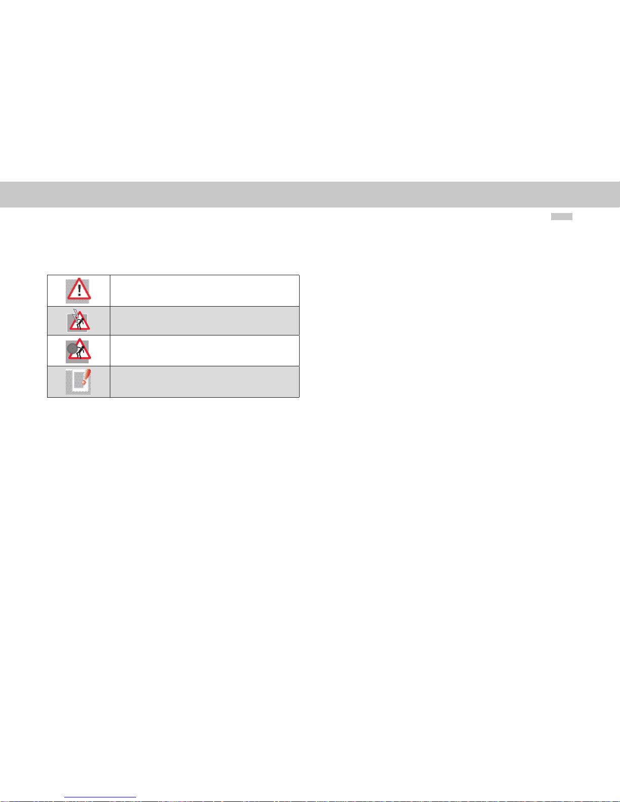
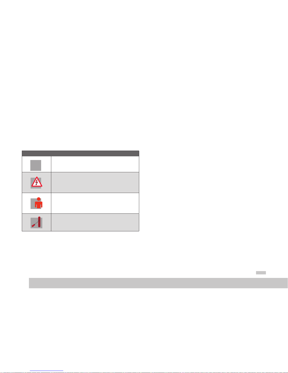
Pictograms
Attention! Incorr ect operatio n may damage the driv e or cause it to malfunction.
Danger from ele ctrical tensio n! Improper conduc t may endanger human life.
Danger from rotat ing parts! The dr ive may start up a utomatically.
Note: Useful information
moog
MSD Servo Drive User Manual Profibus
7
[ Kapitel 1 ]
1 General
1.1 Measures for your Safety
Servo controllers of the MSD Ser vo Drive family are quick and easy to handle. For your
own safety and for the safe functioning of your device, please be sure to observe the
following points:
Read the Operating Manual firs t!
1.
• F ollow the safet y instruction s!
Electric dr ives are subjec t to certain hazar ds:
• Ele ctric voltages > 230 V/460 V:
Dangerously hig h voltages may st ill be present 10 minutes af ter the power
is switched of f. so always make sure the sy stem is no longer li ve!
• Rotating par ts
• H ot surfaces
Your qualification:
• I n order to prevent per sonal injury or d amage to proper ty, only personn el
with elect rical engineer ing qualificatio ns may work on the devi ce.
• K nowledge of the na tional accident pre vention regulati ons (such as VBG4
in Germany)
• K nowledge of st ructure and net working using the C AN fieldbus
U
V
N
L+
RB
L-
L3
L2
L1
U
V
N
L+
RB
L-
L3
L2
L1
During installation observe the following instructions:
• A lways comply wit h the connectio n conditions and tec hnical specifi cations.
• Sta ndards for elect rical installa tion, e.g. cable cross -section s, screening etc.
• Do n ot touch electr onic component s and contact s (electrosta tic discharge
may destroy comp onents)
1.2 Introduction to Profibus
The Profibus implementation in MSD Ser vo Drive is based on the PROFIdrive profile
“Profibus PROFdrive profile version 4.0” dated August 2005.
Performance features in key words
– Data transmission using two-wire twisted pair cable (RS 485)
– Transmission rate: optionally 9.6 K, 19.2 K, 45.45 K, 93.75 K, 187.5 K, 500 K,
1.5 M, 3 M, 6 M or 12 MBaud
– Automatic Baud rate detection
– Profibus address can be set using the rotar y coding switches or alternatively
using the addressing parameters
– Cyclic data exchange reference and actual values using DPV0
– Acyclic data exchange using DPV1
– Synchronisation of all connected drives using freeze mode and sync mode
– Reading and writing drive parameters using the PKW channel or DPV1
1.3 System requirements
It is assumed that you have access to a standard Profibus set-up program or a Profibus
interface driver.

moog
MSD Servo Drive User Manual Profibus
8
1.4 Further documentation
• User manual for commissioning the drive device
• User manual for further parameterisation to customise the application.
• The User Manual can be downloaded as a PDF file from the Product DVD, which is
enclosed the MSD Servo Drive.
• CiA 301 (Rev. 4.0): Application Layer and Communication Profile
• CiA 402 (Rev. 2.0): Device Profile Drives and Motion Control
• Profibus User Organisation „Profidrive - Profil Drive Technology for Profibus and
Profinet“ Version 4.1, May 2006, Order no. 3.172
moog
MSD Servo Drive User Manual Profibus
9
[ Chapter 2 ]
2 Commissioning the
Profibus Interface
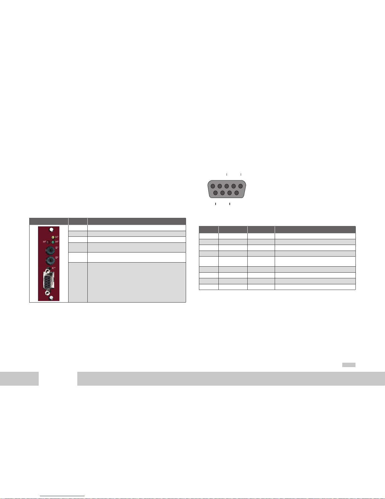
2.1 Connections and user controls
The connections and user controls for the Profibus interface are shown schematically
in Figure 2-1. The LEDs H1, H2, H3 act as status indicators. The rotary coding switches
S1 and S2 can be used to set the Profibus address for the drive. The Profibus cable is
connected to the plug X14.
Front plate No. Comments
H1 LED for status ind ication (yell ow)
H2 LED for status indicati on (red)
H3 LED for status indicati on (green)
S1
Rotary codi ng switch for set ting the Profibus addres s for the
drive = 0x(S2)(S1)
S2
Rotary codi ng switch for set ting the Profibus addres s for the
drive = 0x(S2)(S1)
X14 Profibus cable connection
Table 2.1 Profibus options card
2.2 Plug configuration for the Profibus cable
The Profibus is connected using a nine-pin sub-D plug. The pin assignment is shown in
Fig. 2-2 and described in Table 2.1.
Figure 2.1
X14
12345
6789
RxD
TxD-P
DGND
RxD
TxD-N
VP
5 Volt
Pin assignment of sub-D-plug connector
PIN RS-485 Signal Description
1 SHIELD Earthed shield
2 RP Reserve d for power supply via t he bus
3 B/B’ (red) RxD / TxD-P Send and receiv e data (+)
4 CNTR- P Control signal for rep eater (+)
5 C/C’ DGND
Data reference pote ntial and power supp ly to
terminating resistor (-)
6 VP Po wer supply for termin ating resistor (+)
7 RP Reserve d for power supply via t he bus
8 A/ A’ (gre en) RxD / TxD- N Send and receive dat a (-)
9 CNTR- N Control signal for rep eater (-)
Table 2.2 Description of pin assignment
The pin assignments shown with dark backgrounds in the table are not necessary from
the user’s point of view. The control signals used for the repeaters are optional, and the
power supply for the terminating resistors is provided by the device.
moog
MSD Servo Drive User Manual Profibus
10
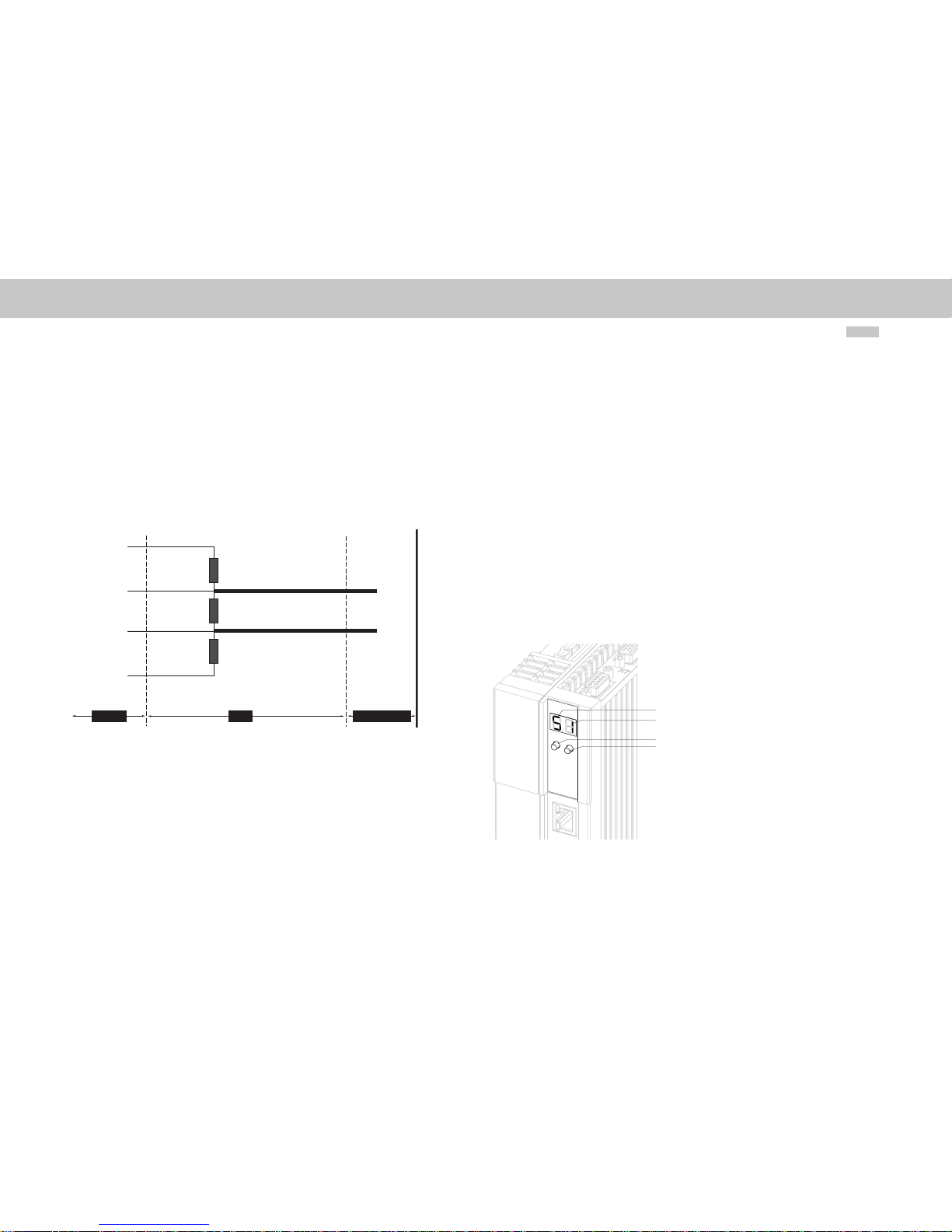
2.3 Bus termination
If the servo controller is initially at the end of the bus system, a plug with an integral
terminating resistor Rt should be used. In addition to the cable terminating resistor in accordance with the EIA-4 85 standard, a pull-down resistor Rd against the data reference
potential DGND and a pull-up resistor Ru against VP are provided. This ensures a defined
no-load potential of 1.1 Volt between pins 3 and 8. In a made-up Profibus cable these
resistors are all incorporated as standard in the Profibus plug and the terminating resistor
can be activated using a switch on the Profibus plug. The following figure shows a SubD 9-pin plug bus termination.
Figure 2.2
Plug
Profibus cable
Device
Vp = 5 Volt (6)
RxD TxD-P (3)
RxD TxD-N (8)
GND (6)
Ru = 390 Ohm
Rt = 220 Ohm
Rd = 390 Ohm
B (red)
A (green)
Sub-D 9-pin plug bus termination
2.4 Setting the drive address
The drive address can be set as standard using the rotary coding switches on the options
card (see Fig. 2-1). The address range runs from 0 to 125. The drive address is not loaded
until a 24 Volt reset has been applied to the device.
The drive address can also be assigned using parameter P 0918 COM_DP_Address.
For this purpose the rotary coding switches must be set to value in excess of 125.
The drive address set by software address is not loaded until a 24 Volt reset has been
applied to the device.
In the MSD Servo Drive Compact the address cannot be set using the switches.
On all devices the bus address can also be set using the buttons on the device, see operating instructions for MSD Servo Drive Compact.
Diagnostics can be performed on the MSD Servo Drive Compact using the internal
control unit in the device. The control unit comprises the following elements that are all
positioned on the front:
• 2-digit 7-segment display (1, 2)
• 2 buttons (3, 4)
Figure 2.3
1
2
3
4
Integrated control unit MSD Servo Drive Compact
moog
MSD Servo Drive User Manual Profibus
11
[ Chapter 2 ]
The following functions and indications are available:
• Indication of the device status
The device status is indicated after switching on the control supply. If an entry is
not made using the buttons for 60 seconds, the display returns to the display of
the device status.
• Indication of the device error status
On the occurrence of an error in the device, the display is immediately switched to
the indication of the error code.
• Parameter setting (indication „PA“)
Reset the device parameter settings to the factory setting
• Ethernet IP address setting (indication „IP“)
Setting for the Ethernet IP address as well as the subnet mask
• Fieldbus settings (indication „Fb“)
Setting e.g. for the fieldbus address
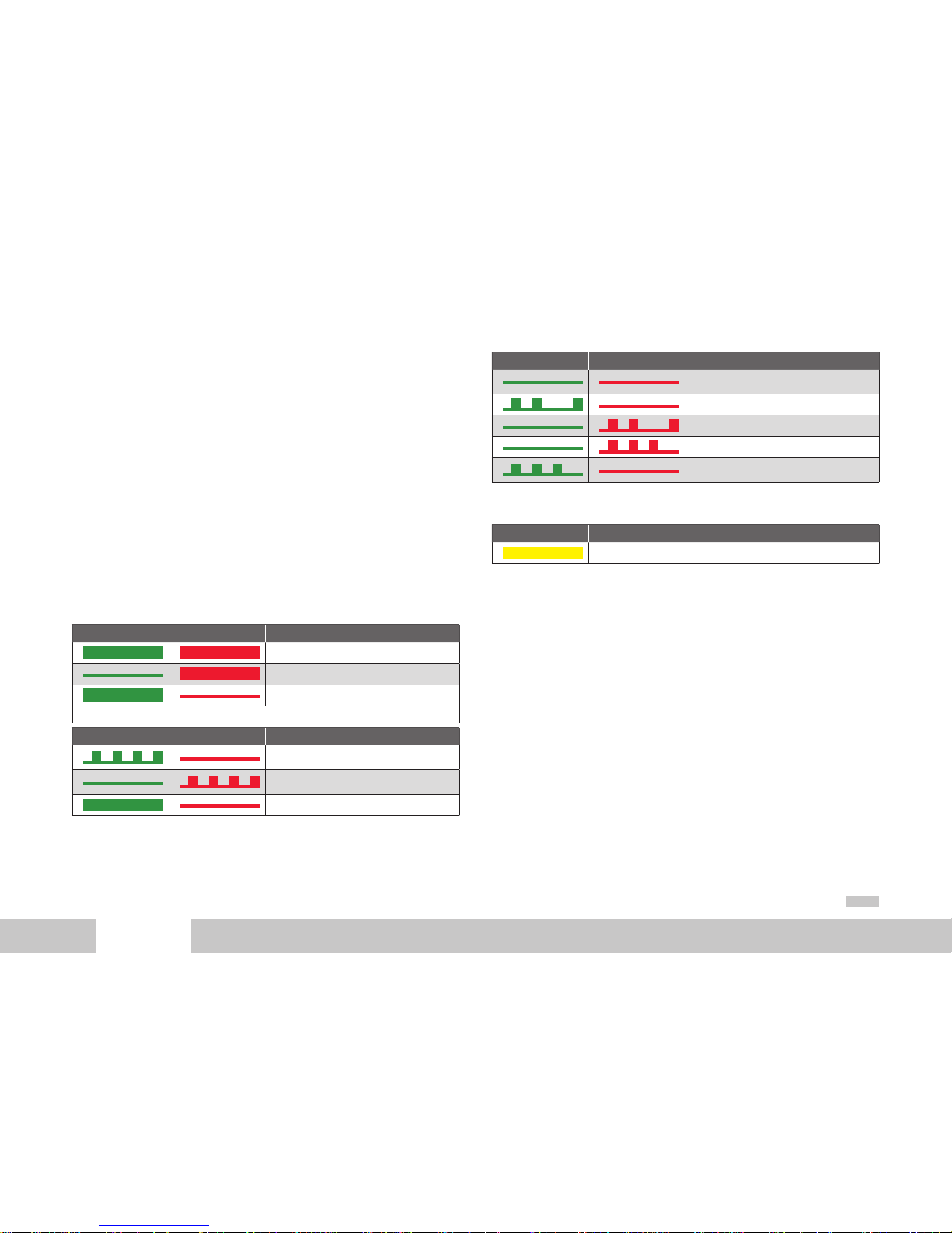
2.5 Operating displays
Options module: Three LEDs are mounted on the options card; these give indications
regarding the current operating status of the module. In Tables 2-2 and 2-3 the operating statuses of the Profibus module are listed, based on the various LED illumination
combinations.
LED 1, green LED 2, red Status
Reset (after s witching on)
ASIC RA M test and initialisation
End of ASIC R AM test and initialisation
Table 2.3 Selftest during diagnostic
LED 1, green LED 2, red Status
Seeking Baud rat e after switching o n without bus
connection
Seeking Baud rat e after the bus conne ction has
already been established
Awaiting parameterisation data
Table 2.4 Operation diagnostics
LED 1, green LED 2, red Status
Communication: Data e xchange without a cyclic
master class 2 con nection. Yellow LED li ghts up.
Communication: Data exchange “clear state”
Incorrect parameterisation data
Incorrect configuration data
Communication: Data e xchange with ac yclic
master class 2 connection.
Table 2.4 Operation diagnostics
LED 3, yellow Status
Device is exchanging data
Table 2.5 Data exchange
2.6 GSD file
The device master data file contains the summary of the device features in a standardised form. The device features include for instance the device name, the bus timing,
the extended services available and the modules that can be selected (telegram types).
In order to use different telegram types, the GSD file must be linked in at the configuration phase of the Profibus network. This file contains, as well as the standard “Profidrive
Profile” telegrams, additional manufacturer-specific telegram types.

moog
MSD Servo Drive User Manual Profibus
12

moog
MSD Servo Drive User Manual Profibus
13
[ Chapter 3 ]
3 Cyclic data transmission –
DPV0
3.1 Parameter process data objects (PPO)
The establishment of communications between a class 1 master and the
MSD Servo Drive servo controller is essentially performed in three phases. Firstly the
MSD Servo Drive is parameterised with the current bus parameters, monitoring times
and drive-specific parameters (phase 1). In the configuration phase a configuration sent
by the master is compared with the actual MSD Servo Drive configuration (phase 2).
Once these two phases have been completed successfully, the cyclic user data traffic
starts (phase 3).
The various telegram types (Parameter Process Data Objects - PPO) are prepared in the
GSD file. These PPOs form the basis of the configuration phase. The project engineer
knows from the GSD file how many bytes are required for the input and output data for
Profibus communication between the master and the servo controller and can use this
information to perform his settings in the configuration tool. As well as the standard
telegrams in accordance with the “PROFIdrive – Profile”, there are additional userspecific telegram types. In addition to the PZD process data channel, the user-specific
telegram make partial use of a PKW parameter channel.
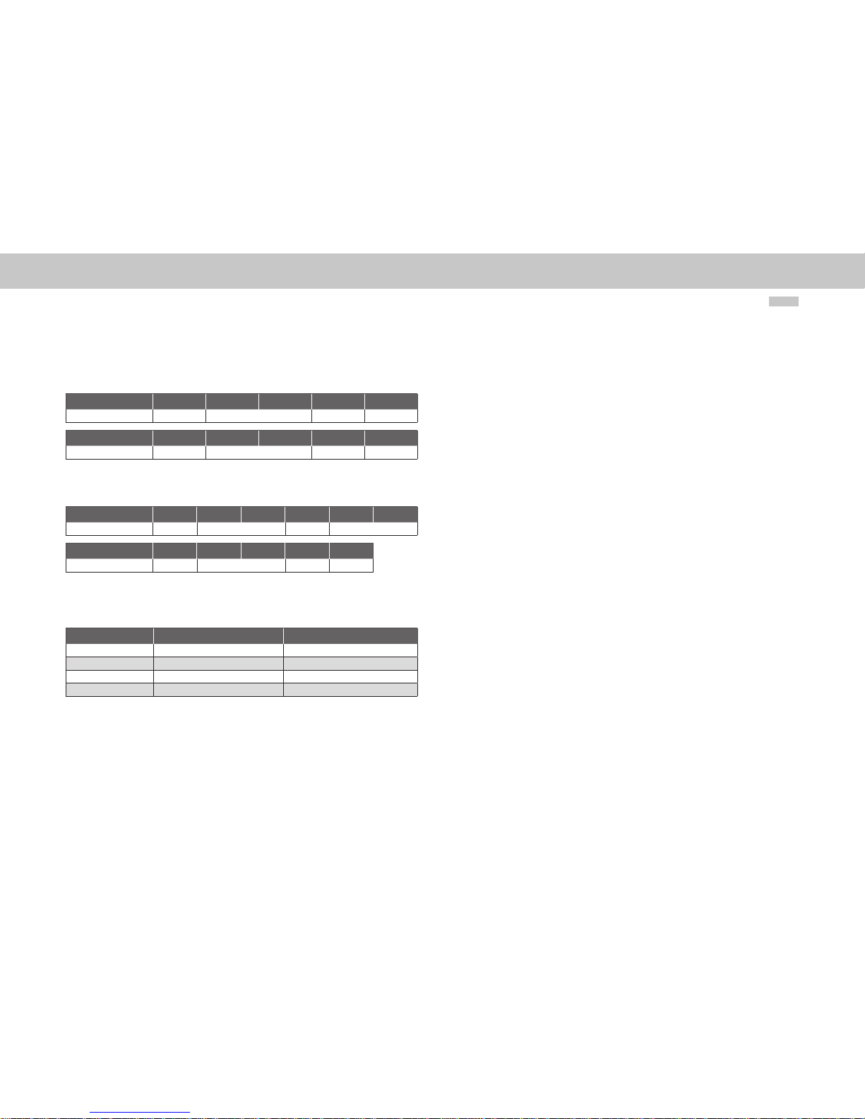
3.1.1 Standard “PROFIdrive” telegrams
The table below lists firstly the standard “Profidrive” telegrams that are supported by the
servo controller. Table 3-1 explains the abbreviations used to assign standard telegrams
to a specific process data channel. The process data channel (abbreviated to PZD) is
grouped by words.
Abbreviation Name Number of words
STW1 Control word 1 1
STW2 Control word 2 1
ZSW1 Status word 1 1
ZSW2 Status word 2 1
NSOLL_A Speed reference 1
NIST_ A Actual speed 1
SAT ZA NW Set selec tion (from the drivi ng set table) 1
AK TSAT Z Current set selectio n (from the driving se t
table)
1
XSOLL_A Reference position 2
XIST_ A Actual position 2
TARP OS_A Reference destination position 2
VEL OCI TY_ A Reference speed 2
Figure 3.1 Abbreviations
Standard telegram 1 is a defined telegram type for speed control. It consists of two input
words and two output words as shown in the following table.
PZD number 1 2
Reference values STW1 NSOLL_A
PZD number 1 2
Actual values ZSW1 NIST_ A
Table 3.1 Standard telegram 1
Standard telegram 7 is a defined telegram type for selecting the driving set. In total 16
driving sets saved in the drive can be selected. The telegram type comprises 2 input
words and two output words as in the following table.
PZD number 1 2
Reference values STW1 SAT ZA NW
PZD number 1 2
Actual values ZSW1 AK TSATZ
Table 3.2 Standard telegram 7
moog
MSD Servo Drive User Manual Profibus
14
Standard telegram 8 is a defined telegram type for positioning with the facility for specifying a positioning speed. It consists of 5 input words and 5 output words as shown in
the following table.
PZD number 1 2 3 4 5
Reference values XSOLL_A STW2 NSOLL_ A
PZD number 1 2 3 4 5
Actual values XIST_ A ZSW2 NI ST_A
Table 3.3 Standard telegram 8
Standard telegram 9 is a defined telegram type for positioning. It consists of 6 input
words and five output words as shown in the following table.
PZD number 1 2 3 4 5 6
Reference values STW1 TARPO S_A STW2 VE LOCI TY_A
PZD number 1 2 3 4 5
Actual values ZSW1 XI ST_A ZSW2 NI ST_A
Table 3.4 Standard telegram 9
Every standard telegram in the device is described in the GSD file by a PROFIdrive Profile
configuration identifier (ID). The following table shows these identifiers for the selec ted
standard telegrams.
Telegram type Data area Identifier (ID)
Standard telegram 1 2 output words and 2 input words 0xC3 0xC1 0xC1 0xFD 0x00 0x01
Standard telegram 7 2 output words and 2 input words 0xC3 0xC1 0xC1 0xFD 0x00 0x07
Standard telegram 8 5 output words and 5 input words 0xC3 0xC4 0xC4 0xFD 0x00 0x08
Standard telegram 9 6 output words and 5 input words 0xC3 0xC5 0xC4 0xFD 0x00 0x09
Table 3.5 Identifier

moog
MSD Servo Drive User Manual Profibus
15
[ Chapter 3 ]
3.1. 2 User-specific PPOs
As well as the standard telegrams that are supported there are in addition further userspecific PPOs (Parameter Process data Objects). The following PPOs are also transmitted
cyclically and in addition to the PZD process data channel partially contain a PKW parameter channel, thereby allowing access to the drive parameter values.
PPO PKW PZD
1 PKE IND PKW
1
PKW 2STW/
ZSW
REFERENCE VALUE /
ACTUAL VALUE
- - - - - - - -
2 PKE IND PKW
1
PKW 2STW/
ZSW
REFERENCE VALUE /
ACTUAL VALUE
PZD
3
PZD
4
PZD
5
PZD
6
- - - -
3* - - - - ST W/
ZSW
REFERENCE VALUE /
ACTUAL VALUE
- - - - - - - -
4 - - - - STW/
ZSW
REFERENCE VALUE /
ACTUAL VALUE
PZD
3
PZD
4
PZD
5
PZD
6
- - - -
5 PKE IND PKW
1
PKW 2STW/
ZSW
REFERENCE VALUE /
ACTUAL VALUE
PZD
3
PZD
4
PZD
5
PZD
6
PZD
7
PZD
8
PZD
9
PZD
10
- - - - ST W/
ZSW
REFERENCE VALUE /
ACTUAL VALUE
PZD
3
PZD
4
- - - - - -
PKE IND PKW
1
PKW 2STW/
ZSW
REFERENCE VALUE /
ACTUAL VALUE
PZD
3
PZD
4
- - - - - -
- - - - ST W/
ZSW
REFERENCE VALUE /
ACTUAL VALUE
PZD
3
PZD
4
PZD
5
PZD
6
PZD
7
PZD
8
- -
PKE IND PKW
1
PKW 2STW/
ZSW
REFERENCE VALUE /
ACTUAL VALUE
PZD
3
PZD
4
PZD
5
PZD
6
PZD
7
PZD
8
- -
- - - - ST W/
ZSW
REFERENCE VALUE /
ACTUAL VALUE
PZD
3
PZD
4
PZD
5
PZD
6
PZD
7
PZD
8
PZD
9
PZD
10
(*) PPO3 is the standard te legram 1
Table 3.6 User-specific Parameter Process data Objects
moog
MSD Servo Drive User Manual Profibus
16
In the drive parameter list there exist two signal tables, which contain all the process
data that can be cyclically read and written for the Profibus communications DPV0. All
possible process data signals that can be written can be found in the signal table
P 1284 COM_DP_SignalList_Write and all possible process data signals that can be read
can be found in the signal table P 1285 COM_DP_SignalList_Read. The most important
parameters that can be read and written are also documented in Chapter 6.
The process data signals that can be writ ten can be configured in the signal table
P 0915 COM_DP_PZDSelectionWrite. The number of process data available to be written
are determined by the PPO type that is selected.
The process data signals that can be read can be configured in the signal table
P 0916 COM_DP_PZDSelectionRead. The number of process data available to be read are
also determined by the PPO type that is selected.
When using standard telegrams the process data signals in the signal tables are automatically configured by the firmware.
A maximum of 15 process data signals can be „mapped“. Here both words and double
words can be used.
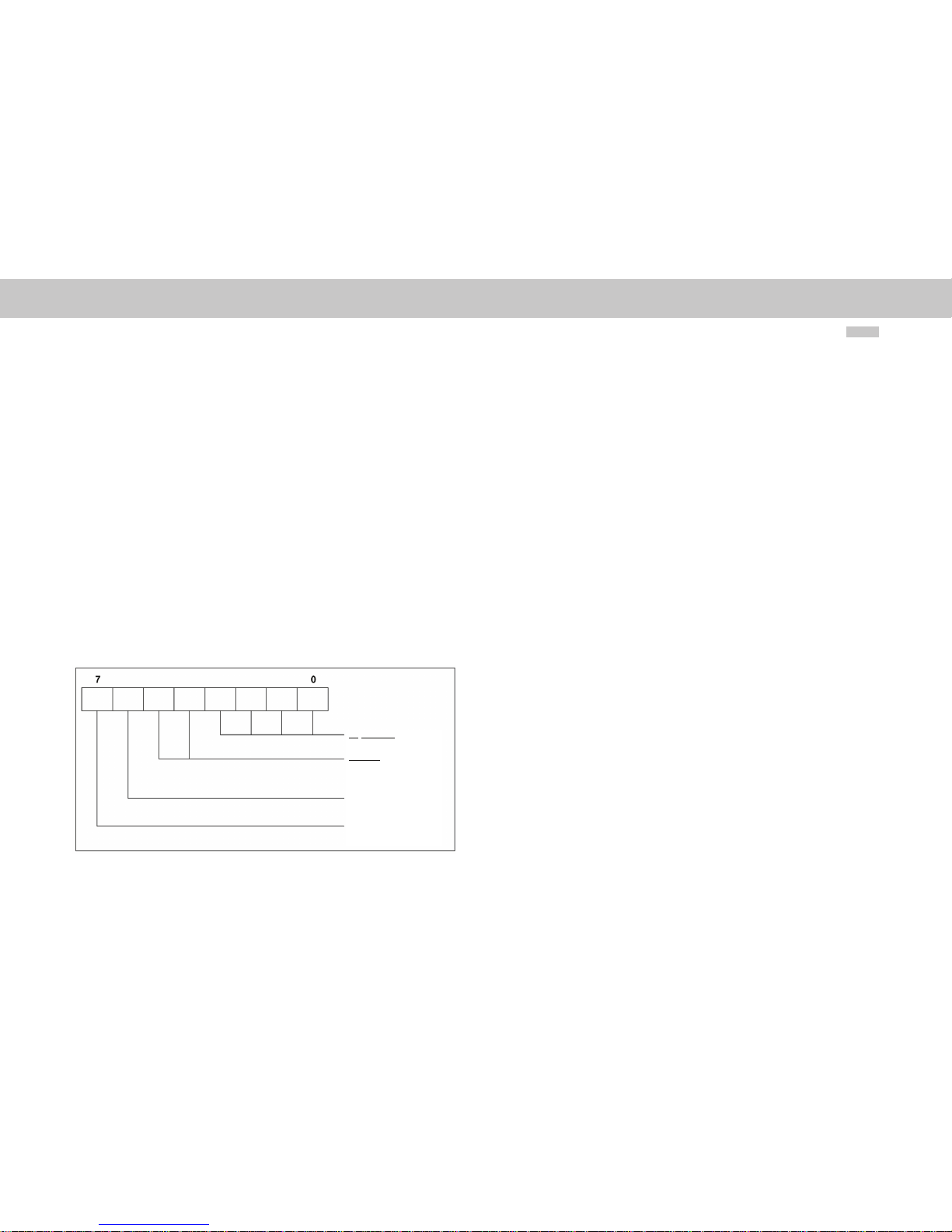
The user-specific drive telegram types are described by a configuration identifier (ID) in
the GSD file. This describes the structure of the cyclic report data using a special identification format shown in the figure below.
Figure 3.2 Identification format (Identifier)
After the parameterisation phase, the master sends the drive a configuration telegram
containing this special identification (ID). On receipt of this, the drive compares the data
in the configuration telegram with the configuration held in the drive. The identifier
determined by the PPO type can be found in the GSD file under the heading “Modules”.
The following table shows these identifiers for the user-specific telegrams.
Length of the data
00 = 1 byte/word
15 = 16 bytes/words
Input/Output
00 = specic identication format
01 = input
10 = output
11 = input/output
0 = byte, 1 = word
0 = consistency over byte/word
1 = consistency over the overall
length

moog
MSD Servo Drive User Manual Profibus
17
[ Chapter 3 ]
PPO
type
Identifier
(ID) Hex
Identifier
(ID) Bin
Evaluation using the special identification format (Figure 3.6)
Reference to Table AK
slave-master
1
0xF3
0xF1
1111 0 011
1111 0 001
4 words input /output data (consistent overall leng th)2 words input /output
data (consistent overall length)
PKW channel
2
0xF3
0xF5
1111 0 011
1111 0 101
4 words input /output data (consistent overall leng th)6 words input /output
data (consistent overall length)
PZD channel
3 0 xF1 1111 0 001 2 words input /output data (consistent overall l ength) PKW channel
4 0xF5 1111 0101 6 words input /output data (consistent overall le ngth) PZD channel
5
0xF3
0xF9
1111 0 011
1111 1 00 1
4 words input /output data (consistent overall leng th)10 words input/outpu t
data (consistent overall length)
PZD channel
0xF3 1111 0 011 4 words inpu t/output dat a (consistent overall l ength) PZD channel
0xF3
0xF3
1111 0 011
1111 0 011
4 words input /output data (consistent overall leng th)4 words input /output
data (consistent overall length)
PKW channel
0xF7 1111 0111 8 words input /output data (consis tent overall length) PZD chann el
0xF3
0xF7
1111 0 111
1111 0 111
4 words input /output data (consistent overall leng th)8 words input /output
data (consistent overall length)
PZD channel
0xF9 1111 10 01 10 words input /output data (consis tent overall length) PKW channel
0xC0
0xCD
0xCD
14 words input/ou tput data (consistent o verall length) PZD channel
0xF3
0xC0
0xCD
0xCD
14 words input/ou tput data (consistent o verall length) PZD channel
0xC0
0xD1
0xD1
18 words input/ou tput data (consiste nt overall length) PK W channel
0xF3
0xC0
0xD1
0xD1
18 words input/ou tput data (consiste nt overall length) PZD channel
0xC0
0xD5
0xD5
22 words input /output data (consistent overall len gth) PZD channel
0xF3
0xC0
0xD5
0xD5
22 words input /output data (consistent overall len gth) PKW channel
Table 3.7 Listing of identifiers

moog
MSD Servo Drive User Manual Profibus
18
PPO
type
Identifier
(ID) Hex
Identifier
(ID) Bin
Evaluation using the special identification format (Figure 3.6)
Reference to Table AK
slave-master
0xC0
0xD9
0xD9
26 words input /output data (consis tent overall length)
0xF3
0xC0
0xD9
0xD9
26 words input /output data (consis tent overall length) PK W channel
0xC0
0xDD
0xDD
30 words input /output data (consistent overall le ngth)
0xF3
0xC0
0xDD
0xDD
30 words input /output data (consistent overall le ngth) PKW channel
Table 3.7 Listing of identifiers

moog
MSD Servo Drive User Manual Profibus
19
[ Chapter 3 ]
3.1. 3 PKW parameter channel
Some PPOs offer an additional cyclic parameter channel. This channel allows drive
parameters to the read and written.
PKW
1st b yte 2nd byte 3rd byte 4th byte 5th by te 6th byte 7th byte 8th byte
PKE (1 word) IND (1 word) P KW1 (1 word) PKW2 (1 word)
The parameter consists of a total of 4 words: the parameter identifier PKE (1 word), the
sub-index IND (1 word) and the parameter identification word, which occupies the data
area PKW1 (1 word) to PKW2 (1 word). The parameter identification is shown by bit s in
the following table.
AK PNU
15 14 13 12 11 10 9 8 7 6 5 4 3 2 1 0
AK
Request or re ply identificat ion (value range 0..15)
PNU
Parameter number (value range 1…4095)
Table 3.8 PKE parameter identification
The following tables list the request identification (master) and the reply identification
(slave).
Request identification Function
0 No request
1 Request parameter value
2 Change parameter value (word)
3 Change parameter value (double word)
4 Read parameter description
5 -
6 Request parameter value (array)
7 Change parameter value (array) (word)
8 Change parameter value (array) (double word)
Table 3.9 Request ide ntification AK (master slave)
Reply identification Function
0 No reply
1 Parameter value sent (word)
2 Parameter value sent (double word )
3 Parameter description sent
4 Parameter value (array) sent (word)
5 Parameter value (array) sent (double wor d)
6 –
7 Request not executable, s ee error no.
Table 3.10 Reply identification AK (Slave Master)
On reply identification 7 the error number sent to the drive from the master is shown in
the area PKW1 to PKW2. The following table lists these error numbers.
Error Statement
0 Impermissible PNU
1 Parameter cannot be changed
2 Lower or upper parameter value l imit transgresse d
3 Defective sub-inde x
4 Not an array
5 Incorrect data type
...
17 Request cann ot be executed be cause of the oper ating status
18 O ther error
Table 3.11 Reply identification AK (Slave Master)
In addition request identification 4 can be used to read a parameter description. The
parameter description receives relevant information regarding the respective parameter.
The following table shows the sub-indexes that can be used to access the individual
parameter structure elements. The sub-index is indicated only by by te 3.
Sub-index Meaning Data type
1 Identifier (ID) V2
2 Number of field elements or string length Unsigned 16
Table 3.12 Parameter description

moog
MSD Servo Drive User Manual Profibus
20
Sub-index Meaning Data type
3 Standardisation factor Floating Point
4 Variable attributes Octet String 2
5 Reserved Octet String 4
6 Nam e (only the first four by tes are sent) VisibleString 16
7 Lower limit value Oct etString 4
8 Upp er limit value Oct etStrin g 4
9 Reserved Octet String 2
10 I D extension extension V2
11 PZD reference parameter Unsigned 16
12 PZD standardisation V2
Table 3.12 Parameter description
The identifier (sub-index 1) in the parameter description identifies additional characteristics of the respective parameter. Table 3-8 describes the meaning of the identifier.
Bit Meaning E xplanation
15 Reserved
14 Array
13 Parameter value ca n only be reset If this bit is set, th e respectiv e parameter
value can be vari ed externally o nly so as to
be set to zero
12 Parameter value was c hanged to a value
different from th e factory set tings
If this bit is set, t he parameter value is
different from th e factory set tings
11 Reserved
10 Additional text ar ray can be called up
9 Parameter cannot be w ritten
8 Standardisation factor and variable attri-
butes not relevan t
This bit is set if th e parameter is of a data
type that ca nnot be used to calcu late any
physical value s (e.g. data type str ing)
0 - 7 Data type of th e parameter value (val ue =
“Profi-Drive table 9”)
Table 3.13 Structure of the identifier
3.2 Master control word
Bit Operating mo de: Speed Control Operating mode: Positioning control
Bit 15
(MSB)
0 Apply relative positioning imme dia-
tely after st art enable
1 Speed mode
Bit 14
0 Normal positioning
1 Speed mode
Bit 13
0 Not used New reference values act ivated by toggling th e
master control wo rd bit 6
1 Not used New reference values are loa ded directly
Bit 12
0 Not used Positioning reference value = a bsolute
1 Not used Positioning reference value = relative
Bi t 11
0 Not used Stop homing run
1 Not used Start homing run
Bit 10
0 No access right s over the PLC
1 Access rights o ver the PLC
Bit 9
0 Jog mode 2 of f Jog mod e 2 off
1 Jog mode 2 o n Jog mode 2 on
Bit 8
0 Jog mode 1 of f Jog mod e 1 off
1 Jog mode 1 o n Jog mode 1 on
Bit 7
0
Error acknowl edgement at rising fl ank 0 1
1
Table 3.14 Master control word

moog
MSD Servo Drive User Manual Profibus
21
[ Chapter 3 ]
Bit Operating mo de: Speed Control Operating mode: Positioning control
Bit 6
0 Deactivate reference value Activate posi tioning set at rising a nd falling flank
(0 1 and 1 0)
1 Activate reference value
Bit 5
0 Freeze ramp gen erator No fee d hold
1 Unfreeze ramp g enerator Feed hold
Bit 4
0 Reset ramp ge nerator Interrupt positioning set
1 Activate ramp generator Do not interrupt positi oning set
Bit 3
0 Controller not enabled
1 Controller enabled (operation enabled)
Bit 2
0 Quick stop ac tive
1 Quick stop inac tive
Bit 1
0 Spin out o f true active
1 Spin out of true inactive
Bit 0
0 Switch of f power stage (OF F)
1 Switch on power st age (ON)
11 Start Homing Procedure / Stop Homing
Procedure
12 Relative positioning
13 Immediate star t on changing the posi tion, speed or
the acceleration
14 Speed mode
15 Apply relative posi tioning immediate ly after star t
enable
Table 3.14 Master control word
Using parameter COM_DP_CtrlConfig bits 6 and 8 can be configured:
Bit
number
Value = 0 (Default-value) Value = 1
The positio ning task can be st arted
with the negati ve and positive flank
(profile 4.0).
The positio ning task can only b e started wit h the
positive flank ( profile 4.1).
The jog mode i s manufacturerspecific
The jog mode b ehaves as descri bed in profile 4.1.
Table 3.15 Master control word
3.2.1 Jog mode speed mode
Bit 8 and 9 of the control word provide a jog mode in the speed mode:
If bit 8 of the parameter P 1267 COM_DP_CtrlCong is set to 0, the drive behaves as
follows (jog mode manufacturer-specific):
• If bit 8 is set to 1, the drive applies the speed that is given in parameter P 1268
COM_DP_RefJogSpeed1.
• If bit 9 is also set to 1, the value in the parameter P 1269 COM_DP_RefJogSpeed2 is
used as the reference value.
• If bit 9 is set to 0 again, P 1268 COM_DP_RefJogSpeed1 is used as the reference
again.
• If bit 8 is set to 0, while bit 9 is still set to 1, there is no change
• If bit 9 is set to 1, the drive applies the negated speed that is given in parameter
P 1268 COM_DP_RefJogSpeed1. The direction of rotation is therefore inverted.
• If bit 8 is also set to 1, the negated value in the parameter P 1269 COM_DP_Ref-
JogSpeed2 is used as the reference value.
• If bit 8 is set to 0 again, P 1268 COM_DP_RefJogSpeed1 is used as the reference
again.
• If bit 9 is set to 0, while bit 8 is still set to 1, there is no change
• In case of negative reference values, a negated speed is positive again.
• The jog mode can only be activated if the motor is at standstill.

moog
MSD Servo Drive User Manual Profibus
22
• If bit 8 of the parameter P 1267 COM_DP_CtrlCong is set to 1, the drive behaves
in accordance with the profile (profile 4.1), page 84 [13]:
• The jog mode can only be activated if the motor is at standstill.
• Bits 4 to 6 of the control word are 0.
• If bit 8 is set to 1, the drive applies the speed that is given in parameter P 1268
COM_DP_RefJogSpeed1.
• If bit 9 is set to 1, the drive applies the speed that is given in parameter P 1269
COM_DP_RefJogSpeed2.
• If bit 8 and 9 are set, there is no change, the old reference value is retained.
3.2.2 Jog mode positioning mode
The jog mode for the positioning mode behaves as for the speed mode. Bit 4 and 5 of
the control word must be set.
3.2.3 Jog mode reference value parameter
• The parameters P 1268 COM_DP_RefJogSpeed1 and P 1269 COM_DP_Ref-
JogSpeed2 are of type Int32 and can be mapped as process data.
Meaning
Bit 0 - 11 N ot used
Bit 12 - 15 Master sign of life
Table 3.16 Master control word 2
If no synchronous application is implemented, the master sign of life need not be transmitted, allowing the entire second status word to be freely assigned.
3.3 Drive status word
Operating mo de: Speed Control Operating mode: Positioning control
Bit 15
(MSB)
Not used
Bit 14
0 „ENPO“ or „Safe Stand still“ not set
1 „ENPO“ or „Safe Stand still“ set
Bit 13
0 Drive rotating
1 Drive stationary
Bit 12
0 Not us ed
Motion reque st confirmation by to ggling this bit
1 Not us ed
Bi t 11
0 Not us ed Homin g point not yet set
1 Not us ed Homi ng point set
Bit 10
0 Frequenc y or speed not reached Target positio n not reached
1 Frequency o r speed reached o r
exceeded
Target position reached
Bit 9
0 No access right s over the PLC
1 Access right s over the PLC granted
Bit 8
0 Speed error outside the tolerance band Posit ioning slippage e rror outside th e tolerance band
1 Speed error within the tolerance band Positioning slippage er ror within the tolera nce band
Bit 7
0 No warning
1 Warning registered
Bit 6
0 Switch on not prevente d
1 Sw itch on prevented
Tab le 3 .17 Drive status word

moog
MSD Servo Drive User Manual Profibus
23
[ Chapter 3 ]
Operating mo de: Speed Control Operating mode: Positioning control
Bit 5
0 Quick stop activated
1 Quick stop deactivate d
Bit 4
0 Spin out of true ac tivated
1 Spin out of tru e deactivated
Bit 3
0 No error
1 Error reported
Bit 2
0 Control b locked
1 Control acti ve (in operation / dr ive responding to re ference values)
Bit 1
0 Power stage inactive (no t ready)
1 Power stage a ctive (ready)
Bit 0
0 N ot ready to star t
1 Ready to start
Tab le 3 .17 Drive status word
Bit Meaning
0-1 Profile generator status
0: Stop
1: Acceleration
2: Positioning wit h allowable spe ed
3: Delay
2 Torque limitation w ith positive dire ction of travel
3 Torque limitation w ith negative dire ction of travel
4 ISD00
5 ISD01
6 ISD02
7 ISD03
Tabl e 3.18 Drive status word 2
Bit Meaning
8 Reserved
9 Reserved
10 Reserved
11 Reserved
12-15 Reserved for Profidrive
Tabl e 3.18 Drive status word 2
If no synchronous application is implemented, the slave sign of life need not be transmitted, allowing the entire second status word to be freely assigned.

moog
MSD Servo Drive User Manual Profibus
24
3.4 Drive status machine
Figure 3.3 GeneralSystem status machine (control via Profibus)
System status Designation Description
0 System initialisation running (star t) In itialisation af ter device reset (e.g. hard-
ware, parameter lis t, controller, …)
1 Not ready to s witch on Ini tialisation comp leted, but no power
supply, or intermedi ate circuit voltage l ess
than switch- on threshold
2 Switch-o n inhibit(switc h on
disabled)
Intermediate ci rcuit voltage gre ater than
switch- on threshold
3 Ready to swi tch on Optional conditions sat isfied (e.g. homing
run, quick stop ina ctive …)
4 Switched on Power stag e enabled
5 Operation enabled Power suppl ied to motor, operation ac tive
6 Quick stop ac tive Quick sto p active*
7 Fault reaction active Fault reaction is a ctive, reference va lues
from the Profibus ma ster are ignored.
8 Fault Drive in fault condition, refe rence values
from the Profibus ma ster are ignored.
* Quick stop c an be triggered by vari ous circumstances. The p arameter P 2218 (MP_Quick StopOC) allows t he type of quick
stop to be sele cted
.
Table 3.19 System statuses
Quickstop option
code
Meaning
0 Disable drive function
1 Slow down on slow down ra mp
2 Slow down on quick stop ra mp
3 Slow down on the current lim it
4 Slow down on the voltag e limit
5 Slow down on slow down ra mp and stay in „quick stop“
6 Slow down on quick stop ra mp and stay in „quick stop“
7 Slow down on the current lim it and stay in „quick stop“
8 Slow down on the voltag e limit and stay in „quick stop“
Table 3.20 Quick s top option code
to perform changes to the control word, STW bit 10 must be set
from system status 2 the Safe Standstill must rst be set and then a posltive ank of the ENPO occur
”Quick stop active”
System status 6
(9) Quick stop
activated
(10) Quick stop
deactivated
“Control active“
System status 5
Error
(13) Error
(5) Controller
blocked
(4) Controller enabled
“Switched on“
System status 4
(6) Power
stage blocked
“Error response active”
System status 7
(12) Standstill
detected
(11) Spin out of
true activated
(3) Power stage
switched on
(6) Power stage
blocked
(14) Error response
ended
(7) Spin out of true or
quick stop activated
“Ready to switch on”
System status 3
“Error”
System status 8
Hardware enable
blocked
(16) Hardware
enable blocked
“Switch on blocked”
System status 2
(2) Quick stop and spin
out of true deactivated
(7) Quick stop or spin
out of true activated
(15) Error acknow-
ledgement
(1) UZK OK (8) UZK too low
“Not ready to switch
on”System status 1
(0) Start
“System initialisation
running”
System status 0

moog
MSD Servo Drive User Manual Profibus
25
[ Chapter 3 ]
System st atus
changeover
Designation Description
0 Star t I nitialisation af ter boot-up completed
1 UZK OK Intermediate circuit vol tage greater than s witch-
on threshold
2 Quick s top and spin out of
true deactivated
Spin out of true de activated ST W bit 1 = 1
Quick stop dea ctivated ST W bit 2 = 1
3 Power s tage switche d on
Power stage s witched on STW bit 0 = 1
4 Controller enabled
Controller enabled STW b it 3 = 1
5 Cont rol blocke d
Control blocked ST W bit 3 = 0 *
6 Power stage blocked
Power stage b locked STW b it 0 = 0
7 Quick s top or spin out of true
activated
Spin out of true ac tivated STW bit 1 = 0
Quick stop ac tivated ST W bit 2 = 0
8 UZK too l ow Intermediate circ uit voltage les s than switch- on
threshold
9 Quick s top activated
Activate quic k stop STW bi t 2 = 0
10 Quick stop deac tivated
Deactivate q uick stop ST W bit 2 =1
11 Spin o ut of true activa ted
Activate spin o ut of true ST W bit 1 = 0
12 Standstill detected Standstill was detected
13 Fault Fault event occurred (can o ccur in any system
status)
14 Fault reaction ended Fault reac tion has ended (e.g. fault sto p ramp)
15 Fault acknowledgement
Acknowledg ement of the repor ted fault STW
bit 7 = 1 or by a rising flank of t he power stage
enable
16 Power stage blocked Po wer stage bloc ked (can occur in any syst em
status)
* Parameter P 0144 (Aut ostart) dete rmines whether the contro l of the operation enable is fla nk-triggered (0) or status -
dependent (1) [Param eter List Motion Profile Basic Settings].
Table 3.21 System status changeovers

moog
MSD Servo Drive User Manual Profibus
26

moog
MSD Servo Drive User Manual Profibus
27
[ Chapter 4 ]
4 Acyclic data transmission –
DPV1
In addition to DPV0 cyclic data communications, which are intended as standard for
quick updates of I/O process data, DPV1 acyclic services are available as one-off events.
They offer the facility for instance to read or write parameters acyclically and thus
without interfering with cyclic data traffic. Telegram type SD2 in accordance with the
following table is used for the DPV1 Profibus-DP extension.
SD LE LEr SD DA SA DSA P SSAP DU FCS ED
Start
Delimiter
Length Length
repeat
Start
Delimiter
Destination
Adress
Source
Adress
Destination
Service
Access
Point
Source
Service
Access
Point
Data
Unit
Frame
Check
Sequence
End Delimiter
68H X X 68H xx xx xx xx X ..
Table 4.1 Profibus SD2 telegram for DPV1 services
The acyclic services can be used equally well by a class 1 master (PLC etc.) and by a class
2 master (PC tool). The following table gives and overview of the acyclic services available in relation to the respective master class.
Acyclic ser vices
Master
class
Meaning DSAP SSAP
Initiate request 2 Establish an acyclic connectio n 32H 31H
Abort request 2 Break off an a cyclic connec tion 32H 0..30H
Read request 2 Rea d request via DP V1 32H 0..30H
Write request 2 Write request via D PV1 32H 0..30H
Data request 2 Data trans fer 32H 0..30H
Read request 1 Rea d request via DP V1 33 33H
Write request 1 Write request via D PV1 33 33H
Alarm 1 Alarm handling 33 33H
Table 4.2 An overview of the acyclic serv ices offered
The access mechanism on DPV1 is always performed according to a
fixed layout
1. Write request (5F):
SD .. DSAP SSAP
DU
Req. id
DU
Slot
DU
Index
DU
Length
DU
User
FCS ED
68H xx 32 30 5F 0 2F n+1 0 ..n xx 16H
2. Write reply (5F):
SD .. DSAP SSAP
DU
Req. id
DU
Slot
DU
Index
DU
Length
FCS ED
68H xx 32 30 5F 0 2F n+1 xx 16H
3. Read request (5E):
SD .. DSAP SSAP
DU
Req. id
DU
Slot
DU
Index
DU
Length
FCS ED
68H xx 32 30 5E 0 2F MA X xx 16H
4. Read reply (5E):
SD .. DSAP SSAP
DU
Req. id
DU
Slot
DU
Index
DU
Length
DU
User
FCS ED
68H xx 32 30 5E 0 2F n+1 0..n Xx 16 H
Each read or write access must first be initiated by a write service on Data Unit Index 47
(2Fhex) (1). This write request gives the slave the information about the request it should
execute. After this the slave acknowledges with a reply telegram (2), which initially contains no reply data.
This is simply an acknowledgement of the request and contains only the mirrored DPV1
header of the request telegram. In the event of an error, a negative reply is sent. To then
read the data from the slave, the master must present a read request (3). If the reply (4)
to this is positive, the user data can be used by the master. In the event of an error, a
negative reply is sent. Figure “DPV1 Read Request” shows the telegram sequence for a
read access. This shows the slave sending a negative read reply to the first read request.
This negative read reply means that the required data cannot yet be provided.

moog
MSD Servo Drive User Manual Profibus
28
Not until the following cycle has the slave executed the request to the extent that it can
send a positive read reply with the requested data.
Figure 4.1 DPV1 Read request
This transmission format is in “Big Endian” (Motorola, the highest byte is transmitted
first).
Word format:
0. byte 1. by te
High byte Low byte
Double word format
0. byte 1. by te 2. by te 3. byte
High byte
High word
Low byte
High word
High byte
Low word
Low byte
Low word
The data unit in the table “Profibus SD2 telegram for DPV1 services” of telegram type
SD2 can be split into five areas:
• Req.id (1 byte)
This is the function number of the DPV1 service. This describes for instance whether a parameter should be read or should be written. More detailed information
can be found in the table “Assignment of the Data Unit”.
• Slot (1 byte)
DPV1 slaves consist of a number of physical or virtual slots. The drive is triggered
by addressing a slot, following which the slot address is not evaluated.
• Index (1 byte)
The index contains the address of the data area in which the slave makes available
the data for a parameter access. In accordance with ProfiDrive this is specified with
the fixed data area number 47.
• Length (1 byte)
Gives the length of the user data that follow. In the case of a read access, the
length must be sufficiently large for the data to be read (max. 240 byte) User (1
byte…n byte) Contains the user data to be processed.

moog
MSD Servo Drive User Manual Profibus
29
[ Chapter 4 ]
Data Unit (DU)
byte
Data Unit
Param
Value Meaning
0 Req.id 48H Idle REQ, RE S Idle REQ, RE SP
51H Data Transport REQ,
RES
Data transpor t REQ,
RESP
RESP
56H Resource Manager, REQ Resource manager REQ
57H Initiate REQ, RES Initiate REQ, RESP
58H Abor t REQ Abort R EQ
5CH Alarm RE Q, RES Alarm REQ, R ESP
5EH Read REQ, RES Read REQ, RESP
5FH Write R EQ, RES Write REQ, RE SP
D1H Data Transpo rt NEG
RES
Data transport RESP
D7H Initiate NEG RES Initiate negative RESP
DCH Alarm NEG RES Interrupt negative RESP
DEH Read NEG RE S Re ad negative RES P
DFH Write NEG RE S Write negative RESP
1 Slot 00H ..FEH Sl ot number
2 Index 2FH Index
3 Length xx Le ngth of the user data (ma x 240 bytes)
4..n UserData xx User data
[Alarms are not curr ently support ed]
Table 4.3 Assignme nt of the data unit
In the following table the telegram format for the user data (Data Unit User Data) for a
DPV1 parameter request and a DPV1 parameter reply are shown.
DPV1 Parameter Request Byte address
Request Header Request reference Request identification 0
Axis No N o. of Parameters (n) 2
1. Parameter adress
Attribute No. of elements 3
Paramter Number (PNU)
Subindex
n. Parameter adres s
..... 4+ 6*(n-1)
Format No. of values 4+ 6*n
Values
...
... ...
4+ 6*n +…+
(format_ n
*am oun t_n)
Table 4.4 Assignme nt of the data unit
DPV1 Parameter Reply Byte address
Reply header
Request reference
(mirror)
Response identification 0
Axis No (mirr or) No. of Paramet ers (n) 2
1. Parameter address
Format No. of values 4
Value / error code
...
No. of para meter
address
... ...
4+…+
(format_ n
*am oun t_n)
Table 4.5 DPV1 Parameter reply

moog
MSD Servo Drive User Manual Profibus
30
The user data are structured as follows:
• Request reference:
The Request Reference is specified by the master and mirrored back by the slave
in the reply telegram. Based on this reference the master can uniquely assign each
reply telegram to a request telegram. A master changes the request reference with
each new request.
• Request ID
This identifier has essentially the task of describing the type of parameter treatment. Currently two different identifiers are defined:
- Requesting for a parameter
- Changing a parameter
Further details on identifiers can be found in the table “User data”.
• Response ID
This identifier contains information on the origin of a request. If a request is
executed correctly, the response ID matches the request ID. If a request cannot be
executed, an identifier in accordance with table “User data” is generated.
• Axis No.
This value allows an individual axis in a multi-axis system to be addressed selectively. (Axis No. 0 single axis).
• No. of Parameters
Number of parameters that are processed in a request.
• Attributes
Describes the individual access to a parameter structure. For instance whether
one may access the actual numerical value or use the parameter description text.
Further information can be found in the table “User data”.
• Number of Elements
When accessing an array or a string, this area contains the filed size or the string
length.
• Parameter Number
Contains the parameter number (PNU).
• Subindex
Addresses the first array element of a parameter or the beginning of a character
string. This also allows access to descriptive texts and text arrays.
• Format
Specifies the respective parameter and ensures a unique assignment of the parameter value in the telegram.
• Number of values
Number of following values.
• Values
Parameter values
Field name Data type Valu e Meaning Comments
Field name Data type Value Meaning Co mments
Request
reference
Unsigned8 0x00
0x01..0xFF
Reserved
Request ID Unsigned 8 0x00
0x01
0x02
0x03..0x03F
0x40..0x7F
0x80..0xFF
Reserved
Request parameter
Change Parameter
Reserved
Manufacturer-specific
Reserved
Response ID Unsigne d8 0x00
0x01
0x02
0x03..0x3F
0x40..0x7F
0x80
0x81
0x82
0x83..0xBF
0xC0..0xFF
Reserved
Request parameter (+)
Change Parameter (+)
Reserved
Manufacturer-specific
Reserved
Request parameter (-)
Change Parameter (-)
Reserved
Manufacturer-specific
Axis No Unsigned8 0x00
0x01..0xFE
0xFF
Device Representative
Ax is-Nu mber 1.. 254
Reserved
Zero = single axi s
No. of
Parameters
Unsigned8 0x00
0x01..0x27
0x28..0xFF
Reserved
Quantity 1..39
Reserved
Limited by DPV1
telegram length
Attribute Unsigned 8 0x00
0x10
0x20
0x30
0x40..0x70
0x80..0xF0
Reserved
Value
Description
Tex t
Reserved
Manufacturer-specific
Table 4.6 User dat a

moog
MSD Servo Drive User Manual Profibus
31
[ Chapter 4 ]
Field name Data type Valu e Meaning Comments
No. of Elements Unsigned8 0x00
0x01..0xEA
0xEB..0xFF
Special Function
Qua ntity 1..23 4
Reserved
Limited by DPV1
telegram length
Parameter
Number
Unsigned16
0x0000
0x0001…
0xFFFF
Reserved
Number 1..65535
Subindex Unsig -
ned16
0x0000…
0xFFFF
Number 1..65535
Format Unsigned8 0x00
0x01..0x36
0x37..0x3F
0x40
0x41
0x42
0x43
0x44
0x45..0xFF
Reserved
Data Types
Reserved
Zero
byte
Word
Double Word
Error
Reserved
No. of Values Unsigned8 0x00..0xEA
0xEB..0xFF
Quantity 0..234
Reserved
Limited by DPV1
telegram length
Error Number Unsig-
ned16
0x0000…
0x00FF
Error Number s
(see table be low)
Table 4.6 User dat a
Error number Meaning
Error number Imp ermissible parameter number
0x00 Parameter value cannot be changed
0x01 Value area of the parameter transgres sed
0x02 Defect ive parameter sub -index
0x03 Parameter is n ot an array
0x04 Incorrec t parameter data type
0x05 Change access w ith value not equal to zer o which is not permit ted
0x06 Änderungszugriff mit Wer t ungleich Null, der nicht erlaubt ist
0x07 Change access o n a descriptive el ement, which cann ot be changed
0x09 No descr iptive text avail able
0x 11 Request cannot be p erformed in the present syste m status
0x14 Impermissible value
Table 4.7 Error number
Error number Meaning
0x15 Reply te legram is too long
0x16 Impermissible parameter address
0x17 Illegal format
0x18 Number of param eter values is inconsi stent
0x19 Request i s for an non-ex istent axis
Table 4.7 Error number

moog
MSD Servo Drive User Manual Profibus
32
4.1 Examples of request and reply telegrams
Write word
Refe r.
Req.
ID
Axis
No.
Pa-
ram.
At tr.
No.
Ele.
Pnu
high
Pnu
Low
Sub
high
Sub
low
Format
No.
Valu-
es
Value
high
Value
Low
0 2 0 1 0x10 0..1 3 0x96 0 0 0x42 1 0 7
Table 4.8 ID:2 Change Parameter, Attr. 0x10: Value; Pnu = 918 = 0x396, Format word= 0x42
Positive reply
Refer.
Req.
ID
Axis
No. Pa-
ram.
0 2 0 1
Table 4.9 ID:2 Change Parameter
• Parameter P 0918 now has the value 7
Write double word
Refer. Req. IDAxis No. Pa-
ram.
At tr. No. Ele. Pnu high Pnu Low
0 2 0 1 0 x10 0 ..1 4 0x FA
Sub high Sub low Format No.
Value s
Value
high
Value
Low
Value l
high
Value l
low
0 0 0x43 1 1 2 3 4
Table 4.10 ID:2 Change Parameter, Attr. 0x10: Value; Pnu = 918 = 0x396, Format word=0 x42
Refer.
Req.
ID
Axis
No. Pa-
ram.
0 2 0 1
Table 4.11 ID:2 Change Parameter
• Parameter P 0884 now has the value 16909060
Read simple parameter value
Read word
Refer.
Req.
ID
Axis
No.
Param.
At tr.
No.
Ele.
Pnu
high
Pnu
Low
Sub
high
Sub
low
0 1 0 1 0 x10 0..1 3 0x9A 0 0
Table 4.12 ID:1 Request Parameter, Attr. 0x10: Value; Pnu = 922 = 0x39A
Positive reply
Refer.
Req.
ID
Axis
No.
Param.
Format
No
values
Value
high
Value
low
0 1 0 1 0x42 1 0 9
Table 4.13 Format word=0x42; Parameter value = 9
Read double word
Refer.
Req.
ID
Axis
No.
Param.
At tr.
No.
Ele.
Pnu
high
Pnu
Low
Sub
high
Sub
low
0 1 0 1 0 x10 0..1 4 0xFA 0 0
Table 4.14 ID:1 Request Parameter, Attr. 0x10: Value; Pnu = 922 = 0x39A
Positive reply
Refer.
Req.
ID
Axis
No.
Param.
Format
No
values
Value
H high
Value
H Low
Value
l high
Value
l low
0 1 0 1 0x43
Table 4.15 Format word=0x43; Parameter value = 0x01020304 = 16909060
Defective accesses
Defective parameter numbers
Refer.
Req.
ID
Axis
No.
Param.
At tr.
No.
Ele.
Pnu
high
Pnu
Low
Sub
high
Sub
low
0 1 0 1 0 x10 0..1 0 9 0 0
Table 4.16 ID:1 Request Parameter, Attr. 0x10: Value; Pnu = 9

moog
MSD Servo Drive User Manual Profibus
33
[ Chapter 4 ]
Negative reply
Refer.
Req.
ID
Axis
No.
Param.
Format
No
values
Value
high
Value
low
0 0x81 0 1 0x4 4 1 0 0
Tab le 4 .17 Format error=0x44; Parameter value = 0 = incorrect parameter
number
Write parameter values array
Refer.
Req.
ID
Axis
No.
Param.
At tr. No. Ele. Pnu high Pnu Low Sub high Sub low Format
No.
Value s
Value 0
high
Value 0
Low
-
Value 4
high
Value 4
low
0 2 0 1 0x10 5 3 0x93 0 0 0x42 5 3 C7 0 0
Tabl e 4.18 ID:2 Change Parameter, Attr. 0x10: Value; Pnu = 918 = 0x396, Format word =0x42
• Parameterwerte = 0x03C7, 0x04F6, 0x04F6, 0x04F6, 0
OK reply
Refer.
Req.
ID
Axis
No.
Param.
0 2 0 1
• Parameter P 0915 now contains the entries for the parameter values.
• No standard telegram smaller than 10 is set up in the device,
since then it could not be overwritten. Use remedy PPO5.

moog
MSD Servo Drive User Manual Profibus
34
Read parameter values array
Read assigned process data reference values
Refer.
Req.
ID
Axis
No.
Param.
At tr. N o. Ele.
Value 0
high
Value 0
Low
Value 4
high
Value 4
low
0 2 0 1 0 x10 5 3 C7 0 0
Table 4.19 ID:1 Attr. : 0x10 Pnu = 915=0x393
OK reply
Refer.
Req.
ID
Axis
No.
Param.
Format
No
Value s
Value 0
high
Value 0
low
Value 1
high
Value 1
Low
Value 2
high
Value 2
Low
Value 3
high
Value 3
Low
Value 4
high
Value 4
low
0 1 0 1 0x42 5 3 0xC7 4 0xF6 4 0xF6 5 0 0 0
Table 4.20 ID: 1 Format: 0x42

moog
MSD Servo Drive User Manual Profibus
35
[ Chapter 5 ]
5 Operating modes
5.1 Speed Control
In speed control mode the speed control reference value can be influenced using 3 bits
in the master control word (3.2).
Figure 5.1 Speed control
Setting the control word bit 4 allows the speed reference value to be taken over by the
ramp generator. The control word bit 5 releases the ramp generator; resetting it freezes
the ramp generator again.
The input of the ramp generator is influenced by the control word bit 6. If bit 6 is set,
the reference value is forwarded. If bit 6 is not set, the reference value zero is forwarded.
True = Activate ramp generator
False = Reset ramp generator
True = Enable ramp generator
False = Freeze ramp generato
True = Activate reference value
False = Deactivate reference
value
Reference value
COM_DP_RefSpeed
(Speed)
RFG = Ramp Function Generator
Reference value
for the closed
speed control
circuit

moog
MSD Servo Drive User Manual Profibus
36
5.2 Speed control circuit and associated control
parameters
Figure 5.2 Speed control circuit
P. n o.: Parameter name Meaning
P 1270 COM_DP_RefSpeed Speed reference value
P 1278 COM _DP_ Acc Acceleration ramp
P 1279 COM_DP_Dec Deceleratio n ramp
P 0167 MPRO_REF_OVR Speed override
P 0371 CON_IP_RefTF Filter time co nstant speed refe -
rence value
P 0402 CO N_SCO N_A ddSRef Additive speed reference value
P 0458 M OT_Snom Nominal speed of m otor
P 0328 CO N_SCO N_S Max Speed limitation (reference value:
nominal speed o f motor)
P 0334 CO N_SCO N_S Max Pos Positive sp eed limitation (refe -
rence value: nominal s peed of
motor)
P. n o.: Parameter name Meaning
P 0333 CO N_SCO N_SM axNeg Negat ive speed limit ation
(reference value: nomina l speed
of motor)
P 0417 CON _SCON _SDif f Speed controller differential
P 1271 COM_DP_ActSpeed Actual speed
P 0320 CO N_SCO N_K p PI speed c ontroller amplifi cation
P 0321 CON _SCON _Tn PI_ speed controller lag time
P 0325 CO N_SCO NFilt erFreq Limit frequenci es for torque
reference value filter
P 0326 CO N_SCO NFilt erAssi Torque reference value filter dra ft
parameter
P 0327 CO N_SCO NFilt erPara Torque reference value filte r
parameter
P 0351 CON_ SCALC_TF Actual speed filter time c onstant
Table 5.1 Control parameter
Torque-controlled motor

moog
MSD Servo Drive User Manual Profibus
37
[ Chapter 5 ]
P. n o.: Parameter name Meaning
P 0401 CO N_SCO N_A ddTRe f Additive torque reference value
P 0330 CO N_SCO N_TM axN eg Ne gative torque limit ation (refe-
rence value: nominal torque)
P 0331 CON _SCON _TMax Pos Positive torqu e limitation (refe -
rence value: nominal torque)
P 0332 CO N_SCO N_TM axS cale Torque scaling factor
P 0339 CO N_SCO N_Tmax Torque limitation (reference
value: nominal torque)
P 0460 M OT_TNom Motor nominal torque
Table 5.1 Control parameter
5.3 Position control
In position control operating mode, based on operating status 5 (see section 3.4) the
drive can change over into various statuses in response to defined bits in the master
control word (3.2). These statuses are explained in Figure 5-2.
Figure 5.3 Position control
A positioning command is activated if the control word bit 4, the feed hold is set via bit
5 and a flank is set on control word bit 6. Further positioning commands can then be
activated via the control word bit 13.
If bit 13 is set, changes to the reference position, positioning speed or positioning acceleration lead directly to a new movement request.
Initial status 5; Control active
ZSW1 bits 10, 13 = TRUE
Speed = zero
Do not interrupt
positioning set
STW1 bit 4 = TRUE
Feed hold set
STW1 bit 5 = TRUE
Activate positioning set
STW1 bit 6 = Flank
Braking with ramp
ZSW bits 10, 13 = FALSE
Start homing
STW1 bit 11 = TRUE
End homing
STW1 bit 11 = FALSE
Homing
running
done
Homing point set
ZSW1 bits 11, 13 = TRUE
Interrupt positioning set
STW1 bit 4 = FALSE
Positioning command active
ZSW1 bits 10, 13 = FALSE
and ank on ZSW1 bit 12
Automatic position
updating inactive
STW1 bit 13 = FALSE
Automatic position
updating active
STW1 bit 13 = TRUE
Flank-controlled
updating of
positioning set
Automatic
updating of
positioning set
Activate positioning
set by ank
STW1 bit 6 0 1 or 1 0
Updating
Intermediate stop
Hold set
STW1 bit 1 = TRUE
No hold set
STW1 bit 1 = FALSE
Speed = zero
Braking with ramp
ZSW bits 10, 13 = FALSE
ZSW1 bits 11, 13 = FALSE

moog
MSD Servo Drive User Manual Profibus
38
If bit 13 is not set, a new movement request is activated only by means of a positive or
negative flank of control word bit 6.
If bit 6 is set in parameter P 1267 COM_DP_CtrlCong, the positioning task is only activated on the positive flank. This corresponds to the last PROFIDrive profile 4.1.
If the feed hold is reset whilst a movement command is ac tive, the drive will be braked
via a ramp to a standstill and is set to the status intermediate stop. The current movement request will not be executed until the feed hold is set again.
A movement request can be interrupted by resetting control word bit 4.
In this case the drive will also be braked to a standstill and set to the status “Control
active”. In the initial status 5, additionally a homing run can be triggered by the control
word bit 11.

moog
MSD Servo Drive User Manual Profibus
39
[ Chapter 5 ]
5.4 Position control circuit and associated control parameters
Figure 5.4 Position control circuit
P. n o: Parameter name Meaning
P 1270 COM_DP_RefSpeed Speed reference value
P 1278 COM _DP_ Acc Acceleration ramp
P 1279 COM_DP_Dec Deceleratio n ramp
P 0167 MPRO_REF_OVR Speed override
P 1276 COM _DP_ Act Pos1 Current actual position
P 0402 CO N_SCO N_A ddSRef Additive speed reference value
P 0458 M OT_Snom Nominal speed of m otor
P 0328 CO N_SCO N_S max Speed limitation
P 0334 CO N_SCO N_S Max Pos Positive sp eed limitation (refe -
rence value: nominal s peed of
motor)
P. n o: Parameter name Meaning
P 0333 CO N_SCO N_SM axNeg Negat ive speed limit ation
(reference value: nomina l speed
of motor)
P 0417 CON _SCON _SDif f Speed controller differential
P 1271 COM_DP_ActSpeed Actual speed
P 1516 SCD_ Jsum Overall moment of inertia
P 0376 CON_ IP_TFFScale S caling for pre-control of acce -
leration
P 1275 COM_ DP_TargetPos Target position
P 1277 COM_DP_PosVelocity Positioning spe ed
Table 5.2 Control parameters
Torque-controlled motor

moog
MSD Servo Drive User Manual Profibus
40
P. n o: Parameter name Meaning
P 0374 CON_ IP_EpsDly Position reference delay
P 0320 CO N_SCO N_K p PI speed c ontroller amplifi cation
P 0321 CON _SCON _Tn PI_ speed controller lag time
P 0325 CO N_SCO NFilt erFreq Limit frequenci es for torque
reference value filter
P 0326 CO N_SCO NFilt erAssi Torque reference value filter
parameter
P 0327 CO N_SCO NFilt erPara Torque reference value filte r
parameter
P 0351 CON_ SCALC_TF Actual speed filter time c onstant
P 0401 CO N_SCO N_A ddTRe f Additive torque reference value
P 0330 CO N_SCO N_TM axN eg Ne gative torque limit ation (refe-
rence value: nominal torque)
P 0331 CON _SCON _TMax Pos Positive torqu e limitation (refe -
rence value: nominal torque)
P 0332 CO N_SCO N_TM axS cale Torque scaling factor
P 0339 CO N_SCO N_Tmax Torque limitation (reference
value: nominal torque)
P 0460 M OT_TNom Motor nominal torque
P 0372 CON_IP_SFFTF Filter time constant speed pre-
control
P 0375 CON_ IP_SFFScale Scaling for pre -control of spe ed
P 0414 CO N_PCO N_P osD iff Position controller differential
(tracking error)
P 0360 CO N_P CON_K p Position controller amplification
Table 5.2 Control parameters

moog
MSD Servo Drive User Manual Profibus
41
[ Chapter 6 ]
6 Homing
6.1 Homing runs performed by the drive
Since relative sensor systems are used, the drive must be homed, triggered by bit 11 in
control word 1. As soon as this bit is set by the master, the drive performs a positioncontrolled homing run using an internal profile generator and determined by homing
run speed, homing run acceleration and employing the strategy saved in the homing run
method.
6.2 Homing run speed
The homing run speed is specified by parameter P 2262 MPRO_402_HomingSpeeds in
the parameter editor [Parameter listMotion ProfileHoming]. The user has the facility
here to specify two different homing run speeds.
1. SpeedSwitch = Speed when moving to the limit switch
2. SpeedZero = Speed when moving to the zero point
6.3 Homing run acceleration
The homing run acceleration is specified by parameter P 2263 MPRO_402_HomingAcc in
the parameter editor [Parameter listMotion ProfileHoming].
6.4 Zeroing offset
Absolute encoders (such as SSI multiturn encoders) present a special case for the homing
run, since they directly generate the absolute position reference. For homing using these
encoders it follows that no movement is required and in some circumstances even no
power to the drive. Furthermore, the zeroing offset must be determined. The type 5
is particularly suitable for this. A zeroing offset can be set using the parameter P0525
ENC_HomingOff [Parameter listMotion ProfileHoming].
6.5 Homing cams, limit switches
The signal for the homing cams can optionally be linked to one of the digital input s, for
which the inputs ISD00 to ISD06 are available.
When homing to the limit switches, the digital input must be selected as a positive limit
switch using selection parameter LCW(5) or a negative limit switch using selection parameter LCW(6). When homing to cams, the parameter HOMSW(10) must be selected.
(see parameter P 0101–P 0107).
P. n o.
Parameter identifier/
Setting
Identifier at MDA 5 Function
P 2261
MPRO_402_ HomingMethod
Digital inputs
(-7) -
move pos. direc tion, for
distance coded encoder
Homing run ty pe for distance -coded
encoder for positive direction
(-6) -
move pos. direc tion, for
distance coded encoder
Homing run ty pe for distance -coded
encoder for negative direction
(-5) -
Act. positi on + homing
offset (multiturn-encoder)
Homing (absolute encoder)
(-4) HO MSW
Homing mode t ype 22
with continuous reference
Homing in progre ss, negative flan k of
the homing cam
(-3) HOMS W
Homing mode t ype 20
with continuous reference
Homing in progre ss, positive fla nk of
the homing cam
(-2) -
No homing mod e (act.
position + homing offset)
No homing run; pos itioning is only
by offset
(-1) -
Reference position =
homing offset (parameter
HOOFF)
Current position=Zero
(0) - Not defin ed N o homing run

moog
MSD Servo Drive User Manual Profibus
42
P. n o.
Parameter identifier/
Setting
Identifier at MDA 5 Function
P 2261
MPRO_402_ HomingMethod
Digital inputs
(1) LCC W
Neg. end swi tch, zero
pulse
Homing run nega tive limit switch an d
zero impuls
(2) LCW Pos . end switch, zero puls e
Homing run posi tive limit switch a nd
zero impuls
(3) HOMSW
Pos. reference cams, zero
pulse at RefNo ck=Low
Homing run to cams , negative
flank,positi ve direction of tra ve + zero
impuls
(4) HOMSW
Pos. reference cams, zero
pulse at RefNock=High
Homing run to cams , positive
flank,positi ve direction of tra ve + zero
impuls
(5) HOMSW
Neg. reference cams, zero
pulse at RefNo ck=Low
Homing run to cams , negative
flank,negativ e direction of trav e +
zero impuls
(6) HOMSW
Neg. reference cams, zero
pulse at RefNock=High
Homing run to cams , positive
flank,negativ e direction of trav e +
zero impuls
(7) to (14) HOMSW
Left reference c am polarity,
zero pulse at RefN ock=Low
Various homing runs to c ams
(15), (16 ) - not defined Reser ved
(17) LCC W N eg. end switch Homing ru n negative limit s witch
(18) LC W Pos. end switch Homing run posi tive limit switch
(19) HOMSW
Pos. reference ca ms, Stop
at RefNock=Low
Homing run to cams , negative
flank,positi ve direction of tra vel
(20) HOMSW
Pos. reference ca ms, Stop
at RefNock=High
Homing run to cams , positive
flank,positi ve direction of tra vel
(21) HO MSW
Neg. reference c ams, Stop
at RefNock=Low
Homing run to cams , negative
flank,negative direction of travel
(22) HOMSW
Neg. reference c ams, Stop
at RefNock=High
Homing run to cams , positive
flank,negative direction of travel
P. n o.
Parameter identifier/
Setting
Identifier at MDA 5 Function
P 2261
MPRO_402_ HomingMethod
Digital inputs
(23) to (30) HOMS W
Left reference c am polarity,
Stop at RefNock= Low
Various homing runs to c ams
(31), (32) -
Not defined Reserved
(33) - Nex t left zero pulse
Zero impulse in ne gative directi on of
travel
(34) -
Left reference c am polarity,
Stop at RefNock= High
Zero impulse in po sitive direct ion of
travel
(35) -
Actual posit ion = Reference position
The instanta neous positio n is the zero
position
The signal for the homing cams can optionally be linked to one of the digital input s,
for which the inputs ISD00 to ISD06 are available. Furthermore the limit switches can
also be used for homing. The assignment of the digital inputs can be found under the
parameter 101 to 107 [Parameter listI/O configurationDigital inputs]. When homing
to the limit switches, the digital input must be selected as a positive limit switch using
selection parameter LCW(5) or a negative limit switch using selection parameter LCW(6).
When homing to cams, the parameter HOMSW(10) must be selected.
The following table shows the necessary assignment of the digital input s for the respective homing run methods.

moog
MSD Servo Drive User Manual Profibus
43
[ Chapter 6 ]
6.6 Homing run methods
The type of homing run is selected by the parameter P 2261 MPRO_402_HomingMethod
[Parameter listMotion ProfileHoming].
Further information can be found in the MSD Servo Drive user manual, on our product
DVD.

moog
MSD Servo Drive User Manual Profibus
44

moog
MSD Servo Drive User Manual Profibus
45
[ Chapter 7 ]
7 Examples of commissioning
using manufacturer-specific
telegrams
7.1 Position control using PPO 5
The following section describes how the drive can be simply and quickly commissioning
in the position control mode.
Firstly the GSD file “LUST0A33.gsd” must be linked in during the Profibus configuration
phase and then the PPO type 5 selected. PPO type 5 consists of a PKW channel (8 byte)
and 10 process data channels (20 byte). The process data area can be freely configured
using this manufacturer-specific telegram. That means that the desired reference values
and actual values can be mapped to a defined process data area. All mappable signals
are listed in two signal tables, which can be accessed using the parameter editor under
the folder Parameter list
ð Fieldbus ð Profibus-DP in the left tree structure of the ope-
rating tool. Within this folder directory, the signal list P 1284 (COM_DP_SignalList_Write)
contains all possible process data signals that can be written, and the signal list P 1285
(DP_SignalList_Read) contains all possible process data signals that can be read.
The user can assign the process data channels freely as required. The actual assignment can be found in the signal tables P 0 915 and P 0916 [Parameter list
ð Fieldbus ð
Profibus-DP]. Signal table P 0915 (COM_DP_PZDSelectionWrite) contains all signals that
can be sent by the control master to the drive. Signal table P 0916 (COM_DP_PZDSelectionRead) contains all signals that can be sent by the drive to the control master.
The following table shows an example of the process data area from the control master
to the drive. For this purpose the sub-indexes in list P 0915 are assigned the stated parameter numbers.
Signal
table
P 0915
Sub-index
PZD area
Parameter
number
Parameter name
Data type
(value range)
0 1 P 0967 Control word (COM_DP_Controlword) U16 (0..65535)
1 2 P 1275 Target position (COM_DP_TargetPos) I32
(-2147483648 ..
2147483647)
2 3 P 1275 Target position (COM_DP_TargetPos)
3 4 P 1280
Control word 2
(COM_DP_Controlword2)
U16 (0..65535)
4 5 P 1277
Positioning velocity
(COM_DP_PosVelocity)
I32
(-2147483648 ..
2147483647)
5 6 P 1277
Positioning velocity
(COM_DP_PosVelocity)
6 7 P 1278 Acceleration (COM_D P_Acc) U16 (0..65535)
7 8 P 1279 B raking deceleration (COM_DP_Dec) U16 (0..65535)
8 9 0 - -
9 10 0 - -
Table 7.1 Example of assignment of the master-slave process data channel
Each sub-index represents a 16-bit wide process data channel. For this reason for instance the target position that is sent as Int32 is mapped to sub-indices 1 and 2 in order
to transmit a real 32 bits. The parameters available for selection and their data types are
listed in chapter 6.
The configuration of the process data channels can be freely selected by the user in the
sequence of the signal assignments. However the data type format must be complied
with.
The following table shows an example of the process data area from the drive to the
master. For this purpose the sub-indexes in list P 0916 are assigned the desired parameter numbers.

moog
MSD Servo Drive User Manual Profibus
46
Signal table
P 0915
Sub-index
PZD area
Parameter
number
Parameter name
Data type
(value range)
0 1 P 0 968
Status word ( COM_ DP_Statuswort)
U16 (0..65535)
1 2 P 1276
Actual position (COM_DP_ActPos 1)
I32
(-2147483648
..
2147483647)
2 3 P 1276
Actual position (COM_DP_ActPos 1)
3 4 P 1281
Status wo rd 2(COM_DP_Sta tusword2)
U16 (0..65535)
4 5 P 1271
Actual speed(COM_DP_
ActSpeed)
I16
(-32768..32767)
5 6 - - -
6 7 - - -
7 8 - - -
8 9 - - -
9 10 - - -
Table 7.2 Example of assignment of the slave-master pro cess data channels
The following parameters must then be set for position control mode.
1. P 0300 CON_CfgCon: PCON(3) [Parameter list ðMotor control]
This parameter allows the control mode to be changed. The setting PCON (Position
Control Mode) means that the drive is in position control mode.
2. P 0301 CON_REF_Mode: RFG(0) [Parameter listðMotion Profile
ðBasic settings]
This parameter allows the mode of the position reference value to be input. The
position reference value can be input directly or via a ramp generator. The setting
RFG (Ramp Function Generator) means that the position reference value is input
via a ramp generator.
3. P 0159 MPRO_CTRL_SEL: Probus(7) [Parameter List ðMotion Profile
ðBasic settings]
This parameter allows the control location to be set. In this instance the control
location is selected as Profibus.
4. P 0165 MPRO_REF_SEL: PROFI(9) [Parameter listðMotion ProfileðBasic
settings]
This parameter allows configuration of the reference value selector. In this instance
the reference values are taken from the Profibus.
Once these settings have been performed, communication can be established between
the master and drive.
7.2 Conversion of reference values and actual
values using factor group parameters
Conversion of reference values and actual values using factor group
parameters
n positioning applications the inputting of reference values and the return of actual
values are generally performed using application-specific user units (mm, degrees, …).
The reference values and actual values of the drive are converted using what are called
factor group parameters [Parameter listðMotion profileðStandardisation/units]. For
these the user has the facility to differentiate between 3 different groups of parameters.
All 3 groups have the same task, which is to convert the user units to the fixed internal
variables used by the servocontroller. The first factor group is based on the CiA 402 standard. The parameters of this group are described in detail in the CANopen specification
CiA 402. The second factor group goes under the heading “Sercos”. The parameters of
this group refer to the Sercos specification “SERCOS interface” (Version 2.4 / February
2005). The parameters of this group are also described in detail in the respective specifi-
cation. The third factor group is called “user spec” and is user-specific group. Since this
factor group is not described in detail elsewhere, the use of parameters of this group is
illustrated by means of an example.
The user can select the factor group using the parameter “MPRO_FG_Type”.

moog
MSD Servo Drive User Manual Profibus
47
[ Chapter 7 ]
Parameter number Parameter name Meaning
P 0283 MPRO_FG_Type
Selecti on of the factor group
(0) = STD/402
(1) = SE RCOS
(2) = USER
Table 7.3 Parameters
The parameters of the USER factor group are listed in the table
below
Parameter
number
Parameter name Meaning Unit
P 0270 MPRO_FG_ PosNorm Sensor re solution [incr/rev]
P 0271 MPRO_FG_Num Numerator (position) [rev ]
P 0272 MPRO_FG_ Den Denominator (position) [P OS]
P 0274 M PRO_FG_SpeedFac Speed factor [rev/(min*SPEED)]
P 0275 MPRO _FG _Acc Fac Acceleration factor [rev/ (sec*sec*ACC)]
P 0284 MPRO_FG _PosUnit Position unit String
P 0285 MPRO_FG_ PosExp Position exponent -
P 0286 MPRO_FG_ PosScaleFac Position factor -
P 0287 MPRO_FG _SpeedUnit Speed unit String
P 0288 MPRO_FG_SpeedExp Speed exponent -
P 0289 MPRO_FG_SpeedScaleFac Speed factor -
P 0290 MPRO_FG _AccUnit Acceleration unit Stri ng
P 0291 MPRO_FG _AccExp Acceleration exponent -
P 0292 MPRO_FG_ AccScaleFac Acceleration factor -
P 0293 MPRO_FG _TorqueUnit Tor que un it Strin g
P 0294 MP RO_F G_To rqueE xp Torque exponent -
P 0295 MPRO_FG _TorqueScaleFac Torque factor -
Table 7.4 USER factor group
These define the internal resolution of the unit for
Position: rev
Speed: rev/min
Acceleration: rev/(sec*sec)
The units are automatically defined by the profiles themselves according to CiA 402 or
Sercos. The units can be input manually in User setting.
The parameters for unit and exponent refer to the display and have no effect on the
standardisation of the variables themselves.
The following three formulae describe the conversion of user units into the units used
internally in positioning mode. They refer to reference position, speed and acceleration.
The quotient of parameters MPRO_FG_Num and MPRO_FG_Den describes the ratio of
user unit to motor revolutions. Furthermore is allows any gearing ratios or advance constants to be incorporated.
Positioning speed
The parameter MPRO_FG_SpeedFac offers the facility to change the number of decimal
points for the positioning speed or the unit of the positioning speed.
Positioning acceleration
The parameter MPRO_FG_ AccFac offers the facility to change the number of decimal
points for the positioning acceleration or the unit of the positioning acceleration.

moog
MSD Servo Drive User Manual Profibus
48
7.3 Examples for setting the user factor group
The positioning instructions should be input in degrees, so that 360° corresponds to
one revolution of the motor (65536 increments per revolution of the motor). The speed
should be input in rpm and the acceleration in rpm/sec. This gives the following values:
P 0270 Sensor resolution = 655 36 [incr/rev]
P 0271 Position numerator = 1 [rev]
P 0272 Position denominator = 360 [POS] **
P 0274 Speed factor = 1 [rev/(min*SPEED)] ***
P 0275 Acceleration factor = 1/60 [rev /(sec*sec*ACC)] ****
P 0284 Position unit (string) = „Degree“
P 0287 Speed unit (string) = „1/min“
P 0290 Acceleration unit (string) = „1/(min*sec)“
** POS = User unit for position
***SPEED = User unit for speed
****ACC = User unit for acceleration
7.4 Speed control using PPO 2
The following section describes how the drive can be simply and quickly commissioning
in the speed control mode. Firstly the GSD file „LUST0A33.gsd“ must be linked in during
the Profibus configuration phase and then the PPO type 2 selected.
PPO type 2 consists of a PKW channel (8 byte) and six process data channels (12 byte).
The process data area can be freely configured using this manufacturer-specific telegram. That means that the desired reference values and actual values can be mapped to
a defined process data area. All mappable signals are listed in two signal tables, which
can be accessed using the parameter editor under the folder Parameter list ð Fieldbus ð
Profibus-DP in the left tree structure of the operating tool. Within this folder direc tory,
the signal list P 1284 COM_DP_SignalList _Write contains all possible process data signals
that can be written, and the signal list P 1285 DP_SignalList_Read contains all possible
process data signals that can be read.
The user can freely assign the process data area. The actual assignment can be found in
the signal tables P 0 915 and P 0916 (Parameter list ð Fieldbus ð ProfibusDP). Signal table P 0915 COM_DP_PZDSelectionWrite contains all signals that can be sent by the control
master to the drive. Signal table P 0916 COM_DP_PZDSelectionRead contains all signals
that can be sent by the drive to the control master.
The following table shows an example of the process data area from the control master
to the drive. For this purpose the sub-indexes in list P 0915 are assigned the desired parameter numbers.
Signal table
P 0915
Sub-index
PZD area
Para meter
number
Parameter name
Data type
(value range)
0 1 P 0967 Control word (COM_DP_Control-
word)
U16 (0..65535)
1 2 P 1270 Reference speed (COM_DP_Ref-
Speed)
I16 (-32768..32767)
2 3 P 1278 Acceleration (COM_DP_Acc) U16 (0..65535)
3 4 P 1279 Braking deceleration (COM_DP_Dec) U16 (0..65535)
4 5 - - -
5 6 - - -
6 7 - - -
7 8 - - -
8 9 - - -
9 10 - - -
Table 7.5 Assignment of the master-slave process data channels
Each sub-index represents a 16-bit wide process data channel. For this reason for
instance an Int32 must be mapped to two sub-indices. The parameters available for
selection and their data t ypes are listed in table „A ssignment of the master-slave process
data channels“.
The configuration of the process data areas can be freely selected by the user in the
sequence of the signal assignments. The only requirement is that the data type format
must be complied with. That means that a 32-bit variable also requires 2 process data
channels.

moog
MSD Servo Drive User Manual Profibus
49
[ Chapter 7 ]
The following table shows an example of the process data area from the drive to the
master. For this purpose the sub-indexes in list P 0916 are assigned the desired parameter numbers.
Signal table
P 0915
Sub-index
PZD area
Para meter
number
Parameter name
Data type
(value range)
0 1 P 0968 Status word ( COM_ DP_Statuswor t) U16 (0..655 35)
1 2 P 1271 Actual speed (COM_DP_Act Speed) I16 (-32768..32767 )
2 3 - - -
3 4 - - -
4 5 - - -
5 6 - - -
6 7 - - -
7 8 - - -
8 9 - - -
9 10 - - -
Table 7.6 Assignment of the slave -master proces s data channels
The following parameters must then be set for speed control mode.
1. P 0300 CON_CfgCon : SCON(2) [Parameter list ð control]
This parameter allows the operating mode to be changed. The setting SCON
(Speed Control Mode) means that the drive is in speed control mode.
2. P 0301 CON_REF_Mode : RFG(0) [Parameter list ð Motion Profile
ð Basic settings]
This parameter determines the mode of reference value input. The position reference value can be input directly or via a ramp generator. The setting RFG (Ramp
Function Generator) means that the speed reference value is input via a ramp
generator.
3. P 0159 MPRO_CTRL_SEL : Profibus(7) [Parameter list ð Motion
Profile ð Basic settings]
This parameter allows the control location to be set. In this instance the control
location is Profibus.
4. P 0165 MPRO_REF_SEL : PROFI(9) [Parameter list ð Motion
Profile ð Basic settings]
This parameter allows configuration of the reference value selector. In this instance
the reference values are taken from the Profibus.
Once these settings have been performed, communication can be established between
the master and drive.
7.4.1 Speed input
All factor group parameters are set to default values. The speed reference value can then
be input scaled to the motor nominal speed. So a value of 16384 corresponds to a speed
reference value of 100% of the motor nominal speed.
By using the control word (section 3.2) the drive can then be operated in speed control
mode.

moog
MSD Servo Drive User Manual Profibus
50
7.5 Mappable parameters
Parameter number Parameter name
Write
(128 4)
Read
(1285)
PZD length
P 0967 COM_DP_Controlword X X 1
P 0968 COM_DP_Statusword - X 1
P 128 0 COM_D P_Controlword2 X X 1
P 1281 COM_DP_Statusword2 - X 1
P 1270 COM_DP_RefSpeed X X 1
P 1271 COM_DP_ActSpeed - X 1
P 0121 M PRO_Input_State - X 1
P 0143 MPRO_Output_ State - X 1
P 1274 COM_DP_RefPos X X 2
P 1276 COM _DP_ Act Pos1 - X 2
P 0207 MPRO_TAB_ActIdx X X 1
P 1275 COM_ DP_TargetPos X X 2
P 1277 COM_DP_PosVelocity X X 2
P 1278 COM _DP_ Acc X X 1
P 1279 COM_DP_Dec X X 1
P 1287 COM _DP_ TMax Pos X X 1
P 128 8 COM_DP_TMaxNeg X X 1
... ... ... ... ...
Table 7.7 Mappable parameters
Further mappable parameters can be found in the signal tables P 1284 (COM_DP_SignalList_Write) and P 1285 (DP_SignalList_Read) [Parameter List ð Fieldbus ð Profibus-DP].

moog
MSD Servo Drive User Manual Profibus 51
[ Chapter 8 ]
8 Profibus parameters
The following table describes the Profibus parameters that are available.
Parameter name Number Value range Default value
Can be
changed
Data type Meaning
COM_DP_CtrlConfig P 126 7 0 – 65535 0 Ja U16 This parameter des cribes the func tion of each bit in the co ntrol word, paramet er 967.
COM_DP_RefJogSpeed1 P 126 8 - 429496729 6 bis 4294967295 0 Ja I32 This para meter contains hom ing speed 1 in the jo g mode
COM_DP_RefJogSpeed2 P 1269 - 42949 67296 bis 429496729 5 0 Ja I32 This pa rameter contains hom ing speed 2 in the jo g mode
COM_DP_RefSpeed P 127 0 -32768 – 3276 7 0 Yes I16 Spe ed reference value, written by the Profibus
COM_DP_ActSpeed P 127 1 -32768 – 3276 7 0 No I16 Actual speed
COM_DP_RefTorque P 12 72 -32768 – 3276 7 0 Yes I16 Torque r eference value, writ ten by the Profibus
COM _DP_ Act Torq ue P 1273 -32768 – 3276 7 0 No I16 Actual torque
COM_DP_RefPos P 127 4 -214748364 8 – 21474836 47 0 Ye s I32 P osition reference va lue (ramp mode), writte n by the Profibus
COM_DP_TargetPos P 1275 -214748364 8 – 2147483647 0 Yes I32 Po sition reference valu e (direct mode), writ ten by the Profibus
COM _DP_ Act Pos1 P 12 76 -21474836 48 – 2147483647 0 No I32 A ctual positio n from 1st position sens or
COM_DP_PosVelocity P 127 7 -21474836 48 – 21474836 47 0 Ye s I32 S peed reference valu e (ramp mode), written b y the Profibus
COM _DP_ Acc P 127 8 0 – 0xFFFF 100 Ye s U16 Accelerat ion reference value (ramp m ode), written by the P rofibus
COM_DP_Dec P 1279 0 – 0xFFFF 100 Yes U16 Deceleration reference valu e (ramp mode), written by t he Profibus
COM_DP_Controlword2 P 1280 0 – 0xFFFF 0 Yes U16 2nd Control value, not use d at first
COM_DP_Statusword2 P 12 81 0 – 0xFFFF 0 No U16 2nd status value, not used at firs t
COM_DP_Bus_Timeout P 1283 0 – 4294967295 5000 Yes U32 Bus timeout
COM_DP_SignalList_write P 128 4 0 – 65535 0 No U16 L ist of parameters t hat can be used as pro cess data reference values
COM_DP_SignalList_Read P 12 85 0 – 65535 0 No U16 L ist of parameters that can be use d as process data a ctual values
COM_DP_TMaxScale P 12 86 0 – 2000 1000 Yes U16 Online torque scaling
COM _DP_ TMa xPos P 128 7 0 – 200 0 1000 Ye s U16 Positive onli ne torque scaling
COM_DP_TMaxNeg P 12 88 0 – 2000 1000 Yes U16 Negative online torque scaling
COM_DP_PZDSelectionWrite P 0915 0 – 65535 967 Ye s U16 This paramete r allows incoming pro cess data to be linked to specific dev ice parameters . The
parameters tha t can be entered are lis ted in parameter P 1284. The sub- index 0 contains the first
process data va lue PZD1 and so on.
COM_DP_PZDSelectionRead P 0916 0 – 65535 968 Ye s U16 T his parameter allow s outgoing process data to be linked to s pecific devic e parameters. Th e
parameters tha t can be entered are lis ted in parameter P 1285. The sub-i ndex 0 contains the fir st
process data va lue PZD1 and so on.
Table 8.1 Profibus parameters

moog
MSD Servo Drive User Manual Profibus
52
Parameter name Number Value range Default value
Can be
changed
Data type Meaning
COM_DP_Address P 0918 0 – 126 126 Yes U16 Station address of th e inverter
COM_DP_TelegramSelection P 0922 0 – 65535 0 Yes U16
COM_DP_SignalList P 0923 0 – 65535 0 No U16 T his parameter list s all “mappable” parameter s and signals for param eters P 0915 and P 0916.
COM_DP_Warning P 0953 0 – 0xFFFF 0 No U16 This parameter fo rwards warning m essages from t he Profibus. The se include bus time out and PLC
stop mode.
COM_DP_Baudrate P 0 963 9.6 – 45.45 kbits/ s 9.6 kbit /s No U16 Current Baud rate for bus co mmunication
COM_DP_DeviceId P 0964 0 – 65535 0 No U16 Th is parameter is for dev ice identificat ion
COM _DP_ Profi leNo P 0965 0 – 65535 0 No U16 Pr ofile number, not suppor ted in the first step
COM_DP_Controlword P 09 67 0 – 0xFFFF 0 Yes U16 Control word for the inte rnal status machi ne
COM_DP_Statusword P 0968 0 – 0xFFFF 0 No U16 Status word for the inte rnal status machi ne
COM_DP_DataStore P 0 971 0 – 255 0 Yes U16 This para meter permits s torage of data in the non-volati le memory.
COM_DP_DefinedParameter P 0980 0 – 65535 0 No U16 This paramete r describes th e defined paramet ers in the serv o controller.
COM_DP_ModifiedParameter P 099 0 0 – 65535 0 No U16 This parame ter describes a ll the parameters i n the servo contro ller that are not set to th e “default“
values.
Table 8.1 Profibus parameters

moog
MSD Servo Drive User Manual Profibus
53
[ Chapter 9 ]
9 Appendix Glossary
AK Request identification
Applicatio n dat set Factor y pre-defined data set for s olution of typical applic ations
Diagnostic data The master reads th e diagnostic dat a from the slave and thus p ermits a central
response to slave malfunctions.
DP Distributed I/O
Master The supervisory controller which provides communications.
MW Flag word
Parameter data The PKW para meter channel is use d to transmit paramete rs cyclicall y to and from
the drive devi ce.
PKW Parameter identification value
PNU Parameter number
ProfiDrive Mode Configuration of the proc ess data channel, co mpatible with th e ProfiDrive profil e.
In contrast to Eas yDrive mode t he system sta tuses are changed by d efined series
of control seque nces. The sys tem status machine d efined in the Profibus standard
specifies the individual system status transitions.
PZD Process data: Th e process data chan nel contains the func tions “Load control and
status”, “Input reference value s” and “Display actual va lues”.
Slave A slave is a bus par ticipant on the Profibus-DP, which in contr ast to the master
responds exclu sively to the reque sts directe d to it.
SPM Spontaneous message
Status machine This des cribes the transit ions betwee n the various sys tems statuses . A status transi-
tions is trigge red by a defined event su ch as a control seque nce or the setting o f
an input.

moog
MSD Servo Drive User Manual Profibus
54

moog
MSD Servo Drive User Manual Profibus
55
[ Chapter
Establishment of communications 13
Examples 32
Examples for commissioning 45
Examples for setting the User Factor Group 48
F
Factor Group-Parameter 46
Factor Group USER 47
Format 30
G
GSD file 11
H
Homing 41
Homing run acceleration 41
Homing cams 41
Homing run method 43
Homing run speed 41
Homing runs performed by the drive 41
I
Identification format (Identifier) 16
Identifier 17
Internal resolution 47
J
Jog mode speed mode 21
L
LEDs 11
Limit switches 41
Index
A
Acceleration unit 48
Acceleration factor 48
Acyclic data transmission DPV1 27
Appendix 53
Assignement of the Data Unit 29
Attributs 30
Axis No. 30
B
Bus termination 10
Bus adress 10
C
Class 1 Master 13
Commissioning 9
Configuration phase 11
Connections 9
Control parameter 36, 39
Control unit 10
Conversion of reference values and actual values 46
Cyclic data transmission DPV0 13
D
Data exchange 11
DPV1 Read request 28
Drive status word 22
Drive status machine 24
E
Error number 31

moog
MSD Servo Drive User Manual Profibus
56
M
Mappable parameters 50
Master control word 20
N
Number of parameters 30
Number of elements 30
Number of values 30
O
Operating displays 11
Operating modes 35
Operation diagnostics 11
P
Parameter channel PKW 19
Parameter number 30
Parameter process data objects (PPO) 13
Position control circuit 39
Position control 37
Perfomance feartures 7
Phase1 13
Phase2 13
Phase3 13
Plug configuration for the Profibus cable 9
Positioning acceleration 47
Positioning mode 22
Positioning speed 47
Position control using PPO 5 45
Position unit 48
Process data 16
Process data signals 16
Profibus parameter 51
PROFIdrive 13
R
Request ID 30
Request reference 30
Response ID 30
S
Sensor resolution 48
Setting the drive adress 10
Speed control circuit and associated control parameters 36
Speed control 35
Speed control using PPO 2 48
Speed factor 48
Speed input 49
Speed unit 48
Subindex 30
System requirements 7
T
Terminating resistor 10
U
User controls 9
User data 30
User-specific PPO‘s 15
V
Values 30
Z
Zeroing offset 41


TAKE A CLOSE LOOK.
Moog solutions are only a click away. Visit our worldwide Web site for more information and the Moog facility nearest you.
moog
Moog GmbH
Hanns-Klemm-Straße 28
D-71034 Böblingen
Phone +49 7031 622 0
Telefax +49 7031 622 100
www.moog.com/industrial
drives-support@moog.com
Moog is a registered trademark of Moog, Inc. and its subsidiaries.
All quoted trademarks are property of Moog, Inc. and its subsidiaries.
All rights reserved.
© 2011 Moog GmbH
Technical alterations reserved.
The contents of our documentation have been compiled with
greatest care and in compliance with our present status of information.
Nevertheless we would like to point that this document cannot
always be updated parallel to the technical further development
of our products.
Information and specifications may be changed at any time. For
information on the latest version please refer to
drives-support@moog.com.
ID no.: CA65645-001, Rev. 2.0, 08/2011
 Loading...