

Page 1

MPT- 90
PAN AND TILT POSITIONER
PRODUCT MANUAL
Page 2

____________________________________________________________________
WARNING
IT IS REQUIRED THAT YOU READ AND FOLLOW ALL INSTRUCTIONS IN THIS MANUAL
BY NOT FOLLOWING THE INSTRUCTIONS IN THIS MANUAL MAY RESULT IN DAMAGE
TO THE EQUIPMENT OR OPERATOR
MOOG
Phone: (847) 498-0700
Email: moogs3service@moog.com
LIMITED WARRANTY
Products manufactured by SELLER are warranted at time of shipment to be free from defects in material and workmanship
under normal use and service. This warranty is only applicable to any of SELLER’s products which BUYER returns to
SELLER within one (1) year from the date of initial delivery, and which SELLER determines to be defective within the terms
of this warranty.
Commercial Off-The-Shelf (OTS) products delivered by SELLER are warranted at time of shipment to be free from defects in
material and workmanship under normal use and service. This warranty is only applicable to any of OTS Products delivered
by SELLER which BUYER returns to SELLER within ninety (90) days from the date of initial delivery, and which SELLER
determines to be defective within the terms of this warranty. SELLER's obligations, with respect to such applicable warranty
returns, are limited to repair, replacement, or refund of the purchase price actually paid for the product, at SELLER's sole
option.
SELLER shall bear round-trip shipment costs of defective Items found to be covered by this warranty. Unless otherwise
agreed, the BUYER shall bear any additional costs which SELLER incurs for repair, dismantling, installation, and transport
as a result of the Product being located in a place other than the destination stated in the Contract or, if no destination is
stated, the place of delivery.
Replaced or repaired parts or Products will carry only the unexpired portion of the original warranty as of the date of notice to
SELLER of the warranty defect. Defective Products or parts thereof may be replaced with either new, factory refurbished, or
remanufactured parts. Defective parts, which have been replaced, shall become the SELLER’s property. This warranty does
not extend to any product sold by SELLER which has been subjected to misuse, neglect, accident, improper installation, or a
use for purposes not included or not in accordance with operational maintenance procedures and instructions furnished by
SELLER, or which has been repaired or altered by BUYER or persons other than SELLER or which has been damaged by
secondary causes, including but not limited to, improper voltages, adverse environment conditions, improper signals, or
products which have had their serial number or any part thereof altered, defaced, or removed . Fuses, air filters, desiccants,
and lamps shall be excluded from the provisions of this warranty, and as to these Items no warranty, expressed or implied, is
made by SELLER. SELLER liability does not cover normal wear and tear or deterioration.
THE FOREGOING, WARRANTY IS IN LIEU OF ALL OTHER WARRANTIES, INCLUDING, BUT NOT LIMITED TO,
WRITTEN, EXPRESS, IMPLIED OR STATUTORY WARRANTIES.
IMPLIED WARRANTIES OF FITNESS FOR A PARTICULAR PURPOSE AND MERCHANTABILITY AND DESIGN
WARRANTIES ARE SPECIFICALLY EXCLUDED AND SHALL NOT APPLY.
SELLER'S OBLIGATIONS AND BUYER'S REMEDIES WITH RESPECT TO DEFECTIVE OR NONCONFORMING
PRODUCTS ARE SOLELY AND EXCLUSIVELY AS STATED HEREIN.
At the time of purchase, the SELLER grants to the BUYER, the option to procure a one or two years warranty extension for
selected custom products at the prices specified in the SELLER’s proposal/contract.
____________________________________________________________________________
MN0090-05 Page 2 of 68 18008
MPT-90 PRODUCT MANUAL
Page 3

____________________________________________________________________
TABLE OF CONTENTS
SECTION OR PAGE
PARAGRAPH TITLE NUMBER
1.0 INTRODUCTION .................................................................................. 6
1.1 SCOPE .................................................................................................................... 6
1.2 CUSTOMER SUPPORT ............................................................................................... 6
1.3 DEFINITIONS, ABBREVIATIONS AND ACRONYMS .......................................... 7
1.4 CONVENTIONS USED IN THIS MANUAL ....................................................................... 8
1.5 SYSTEM DIMENSIONS ............................................................................................... 9
2.0 THEORY OF OPERATION......................................................................... 10
2.1 MODELS ................................................................................................................ 10
2.2 MECHANICAL ......................................................................................................... 10
2.3 POSITION .............................................................................................................. 10
2.4 DRIVE ................................................................................................................... 11
2.5 ELECTRONICS ........................................................................................................ 11
2.6 LIMITS ................................................................................................................... 12
3.0 MPT -90 MODELS ................................................................................ 13
3.1 PAN AND TILT DESCRIPTION ................................................................................... 14
3.1.1 System Input Power – All Models ........................................................................................... 15
3.1.2 IP and Serial Control of Positioner – All Models ..................................................................... 17
3.1.3 Additional Serial Control of Positioner – All Models ............................................................... 18
3.1.4 General Purpose I/O Pass Through & Chassis Ground All Models ....................................... 19
3.1.5 Model 8-PB133, 10/100 Ethernet Ports 1 & 2 ........................................................................ 20
3.1.6 Model 8-PB151, Gigabit Ethernet Base to Port 1 Payload ..................................................... 21
3.1.7 Serial Control Communication to ports ................................................................................... 22
3.1.8 Camera Lens Accommodations .............................................................................................. 23
3.1.9 Video Signal ............................................................................................................................ 24
3.2 MOOG PAN AND TILT CONTROL CIRCUIT BOARD DESCRIPTION ................................. 25
3.2.1 Control Circuit Board Configuration ........................................................................................ 25
3.2.1.1 Circuit Card Access ................................................................................................................. 25
3.2.1.2 PBC Jumper Settings: ............................................................................................................. 29
NOTE All jumper settings, the screened dot is Pin 1. Refer to Figure 10 below. ............................................. 29
3.3 PCB SWITCH SETTINGS ......................................................................................... 32
3.3.1 S2 switch settings for serial communication ports .................................................................. 32
3.3.2 S4 switch settings for serial communication ports .................................................................. 34
_______________________________________________________________________
MN0090-05 Page 3 of 68 18008
MPT-90 PRODUCT MANUAL This document contains U.S. export controlled technical data as regulated by the U.S. Export Administration Regulations 15 CFR Parts 730-774, export, disclosure or transfer contrary to U.S. law is prohibited.
Page 4

____________________________________________________________________
4.0 INSTALLATION ....................................................................................... 35
4.1 UNPACK AND INSPECT ............................................................................................ 35
4.2 QUICK START GUIDE .............................................................................................. 35
4.3 INSTALLATION PROCEDURES - MECHANICAL ............................................................ 35
4.3.1 Site Location ............................................................................................................................ 35
4.3.2 Caution on Mobile Mounting ................................................................................................... 36
4.3.3 MPT-90 Installation ................................................................................................................. 37
4.4 INSTALLATION PROCEDURES – ELECTRICAL ............................................................. 38
4.4.1 Connector installation .............................................................................................................. 38
4.5 MATING RECEPTACLE CONNECTOR WIRING ............................................... 40
4.6 MPT-90 SETUP AND ADJUSTMENT PROCEDURES .................................................... 43
5.0 MOOG PTZ WEB INTERFACE INTERNAL WEB GUI ...................... 44
5.1 CONNECTING THE MPT-90 TO A COMPUTER ................................................ 44
5.2 CONNECTING THE MPT-90 TO A NETWORK .................................................. 46
5.3 MOOG PTZ WEB INTERFACE ........................................................................... 47
6.0 SERVICING / MAINTENANCE ........................................................... 56
6.1 MANUALLY ROTATING THE WORM DRIVE SHAFT (PAN OR TILT) ................................ 56
6.2 INTERNAL ACCESS ................................................................................................. 56
6.3 LIMIT RING (HARD STOP) ADJUSTMENT ................................................................... 57
6.4 DRIVE CHAIN TENSION ADJUSTMENT....................................................................... 60
6.5 PAN AND TILT BEARINGS ........................................................................................ 61
6.6 BACKLASH ............................................................................................................. 61
6.6.1 Backlash Test .......................................................................................................................... 62
6.6.2 Backlash Adjustment ............................................................................................................... 62
7.0 MAINTENANCE & REPAIR ............................................................... 64
7.1 ROUTINE MAINTENANCE ......................................................................................... 64
7.1.1 Fresh Water Wash .................................................................................................................. 64
7.1.2 Inspection Intervals ................................................................................................................. 64
7.1.3 Lubrication ............................................................................................................................... 64
7.1.4 Inspection Items ...................................................................................................................... 65
8.0 FAULT ISOLATION ........................................................................... 66
8.1 INTRODUCTION ...................................................................................................... 66
8.2 MECHANICAL OR ELECTRICAL ................................................................................. 66
8.3 MECHANICAL FAULT ISOLATION ............................................................................... 67
_______________________________________________________________________
MN0090-05 Page 4 of 68 18008
MPT-90 PRODUCT MANUAL This document contains U.S. export controlled technical data as regulated by the U.S. Export Administration Regulations 15 CFR Parts 730-774, export, disclosure or transfer contrary to U.S. law is prohibited.
Page 5

____________________________________________________________________
8.4 ELECTRICAL FAULT ISOLATION ................................................................................ 67
TABLE OF FIGURES
FIGURE TITLE PAGE
Figure 1: Identification Label ................................................................................................ 6
Figure 2: MPT-90 Definitions ............................................................................................... 7
Figure 3: MPT-90 Dimensions ............................................................................................. 9
Figure 4: Feature Comparison Table ................................................................................. 14
Figure 5: Pan & Tilt Unit Major Components ...................................................................... 15
Figure 6: Accessing the Circuit Board ................................................................................ 26
Figure 7: Circuit Board ....................................................................................................... 26
Figure 8: Circuit Board Components I ................................................................................ 27
Figure 9: Circuit Board Components II ............................................................................... 28
Figure 10: Jumper Locations .............................................................................................. 29
Figure 11: PCB Switches ................................................................................................... 32
Figure 12: Mounting Base .................................................................................................. 37
Figure 13: Worm Drive ....................................................................................................... 56
Figure 14: Tilt Limit Ring (Hard Limit) Adjustment.............................................................. 58
Figure 15: Pan Limit Ring (Hard Limit) Adjustment ............................................................ 59
Figure 16: Drive Chain ....................................................................................................... 60
Figure 17: Drive Chain Adjustment .................................................................................... 61
Figure 18: Pan & Tilt Axis Backlash Test & Adjustment ..................................................... 63
Figure 19: AeroShell 64 ..................................................................................................... 65
_______________________________________________________________________
MN0090-05 Page 5 of 68 18008
MPT-90 PRODUCT MANUAL This document contains U.S. export controlled technical data as regulated by the U.S. Export Administration Regulations 15 CFR Parts 730-774, export, disclosure or transfer contrary to U.S. law is prohibited.
Page 6
____________________________________________________________________
Model Number
Serial Number
1.0 INTRODUCTION
The purpose of this manual is to provide the MPT-90 Moog Pan and Tilt operator with
the required information necessary to install, operate, troubleshoot and maintain, the
MPT-90 to a level approved by the manufacturer, Moog Inc.
1.1 Scope
Read these instructions before installing or operating the MPT-90 Pan and Tilt.
This manual provides basic installation and operation information. In order to use this
document, the reader must have a basic knowledge of Windows-based PC computers
and adequate mechanical ability.
1.2 Customer support
If information beyond the scope of this manual is required, or you require assistance
with the setup, operation, maintenance, and troubleshooting of this product, refer to
this document. If you still have questions, please contact us at:
Moog, Inc.
Sensor and Surveillance Sales and Marketing
Northbrook, IL USA 60062
Telephone: 1-800-247-6563
(847) 498-0700
Email: moogs3service@moog.com
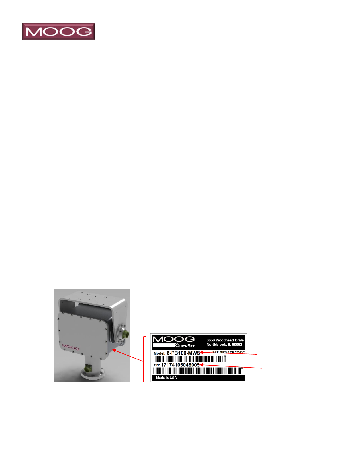
To help us better assist you we recommend that you are at the equipment and ready
with all available details including model & serial number before contacting Moog.
Refer to Figure 1.
Figure 1: Identification Label
The identification label is attached to the underside of the positioner.
_______________________________________________________________________
MN0090-05 Page 6 of 68 18008
MPT-90 PRODUCT MANUAL This document contains U.S. export controlled technical data as regulated by the U.S. Export Administration Regulations 15 CFR Parts 730-774, export, disclosure or transfer contrary to U.S. law is prohibited.
Page 7
____________________________________________________________________
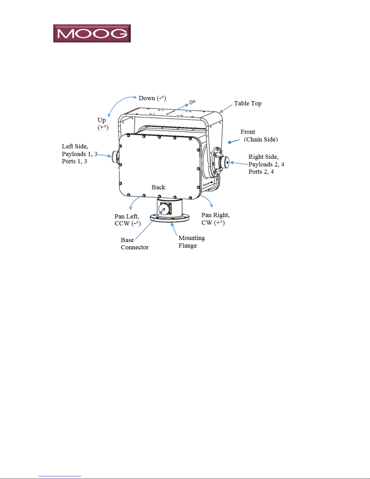
1.3 DEFINITIONS, ABBREVIATIONS AND ACRONYMS
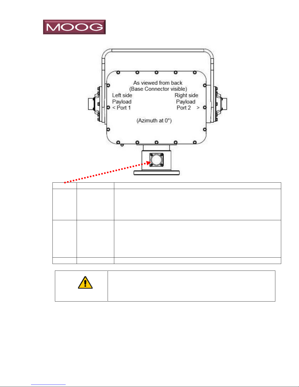
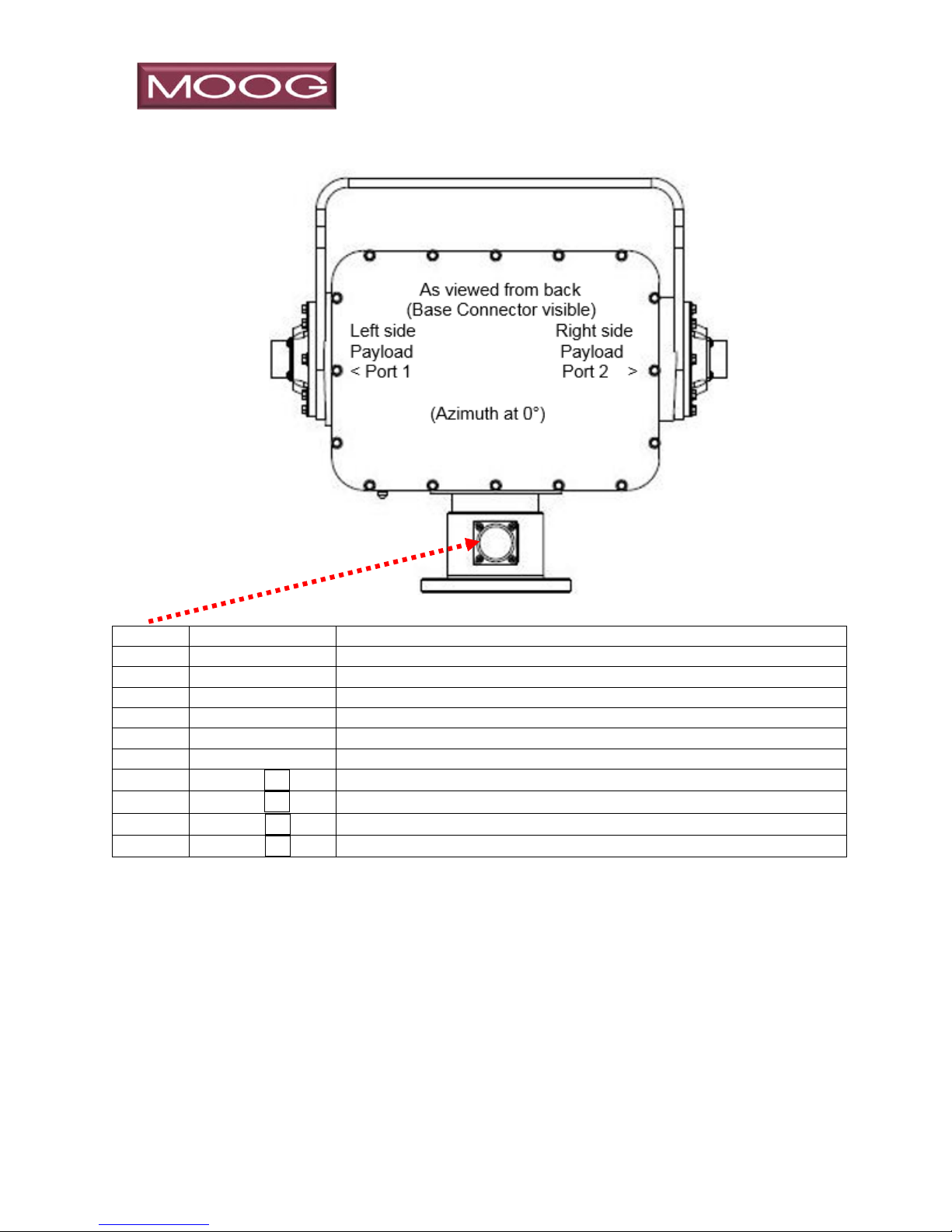
Figure 2: MPT-90 Definitions
Front: the front of the P&T is the side with the Chain Drive under the cover. Most
Moog P&T units have a label on the left side (although shown on right side in
the depiction above) pointing toward the front. Refer to Figure 2.
Zero (0°) Azimuth: typically, the center of azimuth rotation on non-continuous units,
“0° Azimuth” is when the base connector is orientated opposite of the chain
side. When positioned at 0° a cable connected to the base connector would
egress out the “back” of the unit, 180° away from the front.
Left & Right – the left and right side are considered from the perspective of a camera.
With a camera mounted toward the front, an observed video image would
providing the perspective: to “Pan Left”, you would move the positioner
Counter Clock Wise (CCW) as viewed from the top. Moving to the right or
CW increments the degree heading while moving to the left or CCW will
decrement the heading in degrees.
Up & Down – moving upward means the table top is moving toward the rear of the
unit and the indicated position would increment as the elevation increases.
Moving downward would decrement the position in degrees.
_______________________________________________________________________
MN0090-05 Page 7 of 68 18008
MPT-90 PRODUCT MANUAL This document contains U.S. export controlled technical data as regulated by the U.S. Export Administration Regulations 15 CFR Parts 730-774, export, disclosure or transfer contrary to U.S. law is prohibited.
Page 8
____________________________________________________________________
WARNING
IMPROPER USE OF THIS PRODUCT CAN CAUSE SEVERE
BODILY INJURY OR DAMAGE THE EQUIPMENT.
CAUTION
IMPROPER USE OF THIS PRODUCT CAN DAMAGE THE
EQUIPMENT.
Base connector – on base of unit, in a fixed position related to its mounting flange,
egressing out opposite the front at 180°.
The following list of acronyms are used in this manual:
DC Direct Current
EIA Electronic Industry Association
GIG-E Gigabit Ethernet, aka 1000BASE-T
GUI Graphic User Interface
HD-SDI High Definition-Serial Digital Interface
in Inches
I/O Input / Output
lbs. Pounds
mm millimeters
MPT Moog Pan & Tilt
PCB Printed Circuit Board
P & T Pan & Tilt, also known as Positioner
TIA Telecommunications Industry Association
VAC Volts Alternating Current
VDC Volts Direct Current
VRMS Volts Root Mean Square
1.4 Conventions Used in this Manual
Boldface highlights key user interface components. WARNING, CAUTION,
and NOTE highlight statements that identify potential hazards that may occur
if this equipment is not used properly.
NOTE
Notes contain important information about the product or procedure.
_______________________________________________________________________
MN0090-05 Page 8 of 68 18008
MPT-90 PRODUCT MANUAL This document contains U.S. export controlled technical data as regulated by the U.S. Export Administration Regulations 15 CFR Parts 730-774, export, disclosure or transfer contrary to U.S. law is prohibited.
Page 9
____________________________________________________________________
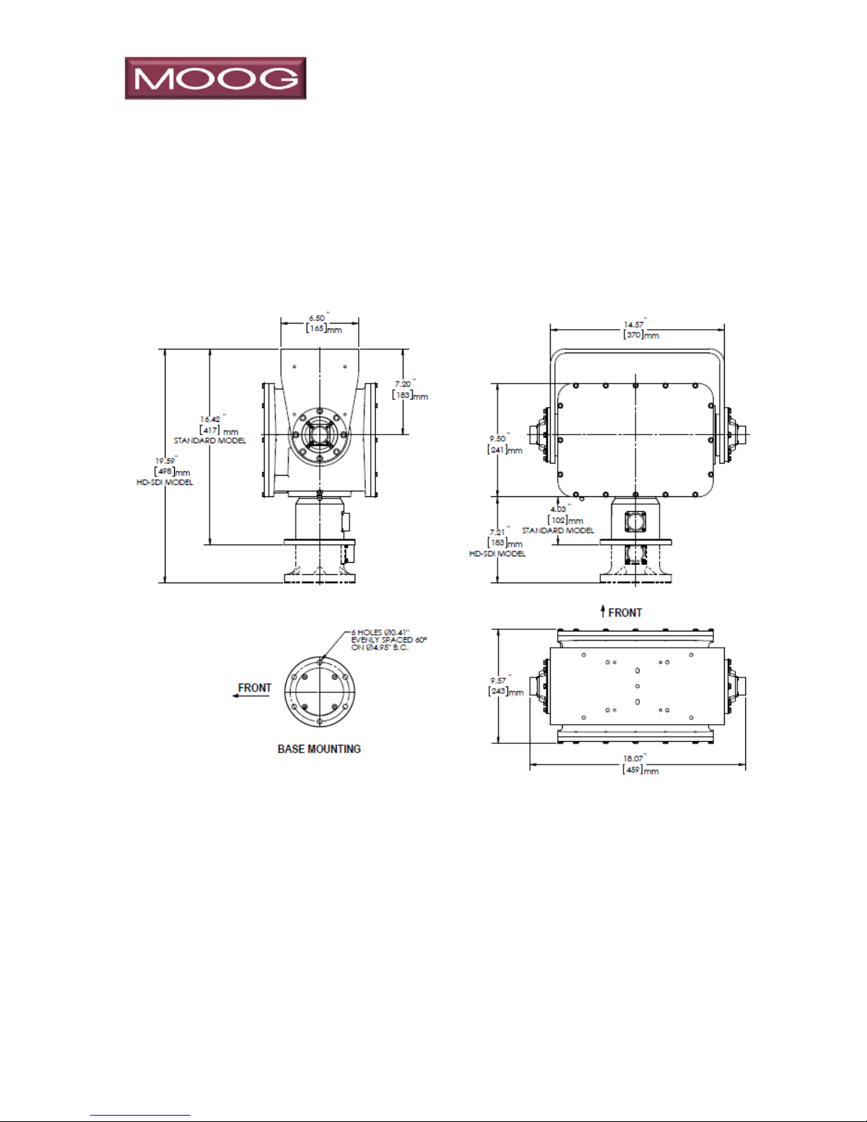
1.5 System Dimensions
Dimensions are per the Figure 3.
Figure 3: MPT-90 Dimensions
This drawing shows the overall dimensions for both the standard base model
and the taller HD-SDI version models.
_______________________________________________________________________
MN0090-05 Page 9 of 68 18008
MPT-90 PRODUCT MANUAL This document contains U.S. export controlled technical data as regulated by the U.S. Export Administration Regulations 15 CFR Parts 730-774, export, disclosure or transfer contrary to U.S. law is prohibited.
NOTE
Page 10

____________________________________________________________________
2.0 THEORY OF OPERATION
2.1 Models
The MPT-90 is available is several Continuous rotation versions or in a NonContinuous configuration. The continuous rotation versions utilize an electrical
slip ring assembly to allow for 360 degrees of pan rotation capability while
providing connectivity to the positioner and payload. Overall connectivity
between the base connector and the payload ports is limited by the number
of conductors in the slip ring, and models vary based on the types of signal
passed through the slip ring.
The Non-Continuous configuration is limited in azimuth rotation, but is factory
default set to 435° of total rotation, with the indicated 0° being the center of
that rotation. The user may set “limit rings” internal to the positioner that will
activate switches to reduce the amount of azimuth travel if desired. Limit rings
are also standard on the tilt mechanism for all models, set at ±90° from the
table top’s horizontal position. Additionally, all units have software adjustable
travel limits.
2.2 Mechanical
Each axis of rotation is rigidly attached to a large 60 tooth helical gear. These
gears are meshed with a worm gear (essentially a 1 tooth gear) that is part of
a steel shaft supported by tapered roller bearings, mounted in an aluminum
“carrier”. The bearings are pre-loaded to prevent lateral play, and the carrier
position is adjustable allowing the worm optimum mesh with helical gear, with
negligible backlash. With the exception of the backlash in the worm drive, the
pan & tilt axis of motion cannot move unless the worm gear is driving it. This
allows the payload to be locked in position even when power is removed.
Mechanical drive mechanisms for Pan and Tilt axis of motion are nearly
identical, with the exception of slight differences in the chain drive sprocket
ratios.
2.3 Position
Position is measured by incremental encoders mounted on-axis to the main
helical gear which read/report actual position inclusive of any system
backlash. Each encoder utilizes an “index” signal that occurs once per
revolution. This index signal is used during the factory installation homing
routine and calibrates the axis of motion 0° azimuth and 0° elevation absolute
position. Position is stored in memory when powered down, allowing the
positioner to know its position when powered up. Since worm gears of this
ratio lock the unit into position, no movement is expected in an unpowered
state, however, each time the axis of motion crosses the index pulse, the unit
will recalibrate position based on the initial homing cycle.
_______________________________________________________________________
MN0090-05 Page 10 of 68 18008
MPT-90 PRODUCT MANUAL This document contains U.S. export controlled technical data as regulated by the U.S. Export Administration Regulations 15 CFR Parts 730-774, export, disclosure or transfer contrary to U.S. law is prohibited.
Page 11

____________________________________________________________________
2.4 Drive
The drive mechanism consists of two 1.8° stepper motors, driven by a 10:1
micro-step motor driver. The motor drivers are provided with DC source
voltage, and enable, direction and pulse signals. 2000 pulses are required for
the motor to turn 1 revolution. Each motor has a 12 tooth sprocket to drive the
worm-carriers via a chain drive. The chain is tensioned with an adjustable
idler, and the chains drive the carriers mentioned above. The pan carrier uses
a 28 tooth sprocket where the tilt uses a 30 tooth sprocket, giving the tilt a
slight increase in ratio reduction.
2.5 Electronics
The controller provides two fundamental types of moves: open loop “jog”
moves where the user specifies direction and velocity, and automated moves
where the controller is managing the move.
Stepper motors require starting at a nominally low speed, and may then be
accelerated by increasing the frequency of the pulse to the motor driver. In jog
mode, the unit will begin a move at a pre-determined speed and accelerate to
the commanded speed. When the jog command is terminated, the pulses
stop quickly decrease in frequency to zero, preventing an abrupt stop.
In automated moves, the microcontroller determines which direction it must
go, then manages the move by controlling acceleration, running at the
commanded speed during the move while monitoring position. The start
speed, acceleration rate and maximum move speed are user adjustable.
When the unit arrives at a pre-determined distance from the commanded
position, a deceleration process begins, slowing the unit to a stop at the
intended destination. User may set the distance from the final destination
where the slow down process starts. These adjustments allow the user to
tailor the motion profile to optimize for the type and size of the payload. For
example, you may wish to position a short range camera system with more
aggressive moves than a satellite dish, due to its size. A more complete
description of adjustments is in the protocol manual.
Additional electronic capabilities provide inner-connections between the
multiple serial ports on the unit, allowing the user to command the positioner
and payloads using various command methods.
_______________________________________________________________________
MN0090-05 Page 11 of 68 18008
MPT-90 PRODUCT MANUAL This document contains U.S. export controlled technical data as regulated by the U.S. Export Administration Regulations 15 CFR Parts 730-774, export, disclosure or transfer contrary to U.S. law is prohibited.
Page 12

____________________________________________________________________
2.6 Limits
Elevation range of motion may be limited in all models both electronically and
mechanically. Additionally, non-continuous rotation models have limit settings
for the azimuth range of motion. “Soft Limits” are software settable, and are
primary method used to limit motion. The P&T units are shipped with the soft
limits set at the maximum range of motion, although the range of motion may
be limited by using the included software. Soft limits should always be set a
minimum of 0.2° beyond any position to be stored as a preset position; the
user should not set a preset position on a soft limit. Please refer to the
MN00307 Moog PTZ Controller Software Manual for instructions on how to
set the soft limits.
Mechanical switches to limit travel (“hard limits”) are provided on the elevation
for continuous rotation models, and on both axis of motion for non-continuous
models. These consist of plastic, moveable, color coded “trip rings” that
trigger a microswitch that tells the microcontroller to stop motion in that
direction, while allowing reverse motion. These should be considered a
secondary method of limiting motion, as there are software limits (“soft limit”)
provided as well. The default setting for the hard limits is slightly beyond the
default soft limit setting at the maximum range of normal motion for the
positioner and the user should not attempt to increase the range of motion
without consultation with the factory. Additionally, it is recommended that hard
limits should always be set at minimum 2° beyond the soft limits. It is not
necessary for the user to adjust the hard limit settings unless they wish to
provide a secondary, redundant method of assuring the unit not travel beyond
the soft limits.
_______________________________________________________________________
MN0090-05 Page 12 of 68 18008
MPT-90 PRODUCT MANUAL This document contains U.S. export controlled technical data as regulated by the U.S. Export Administration Regulations 15 CFR Parts 730-774, export, disclosure or transfer contrary to U.S. law is prohibited.
Page 13

____________________________________________________________________
3.0 MPT -90 MODELS
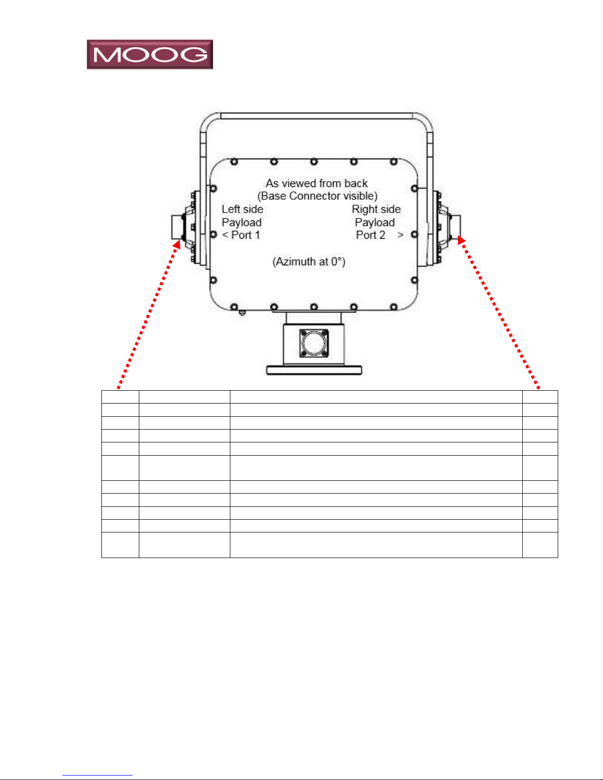
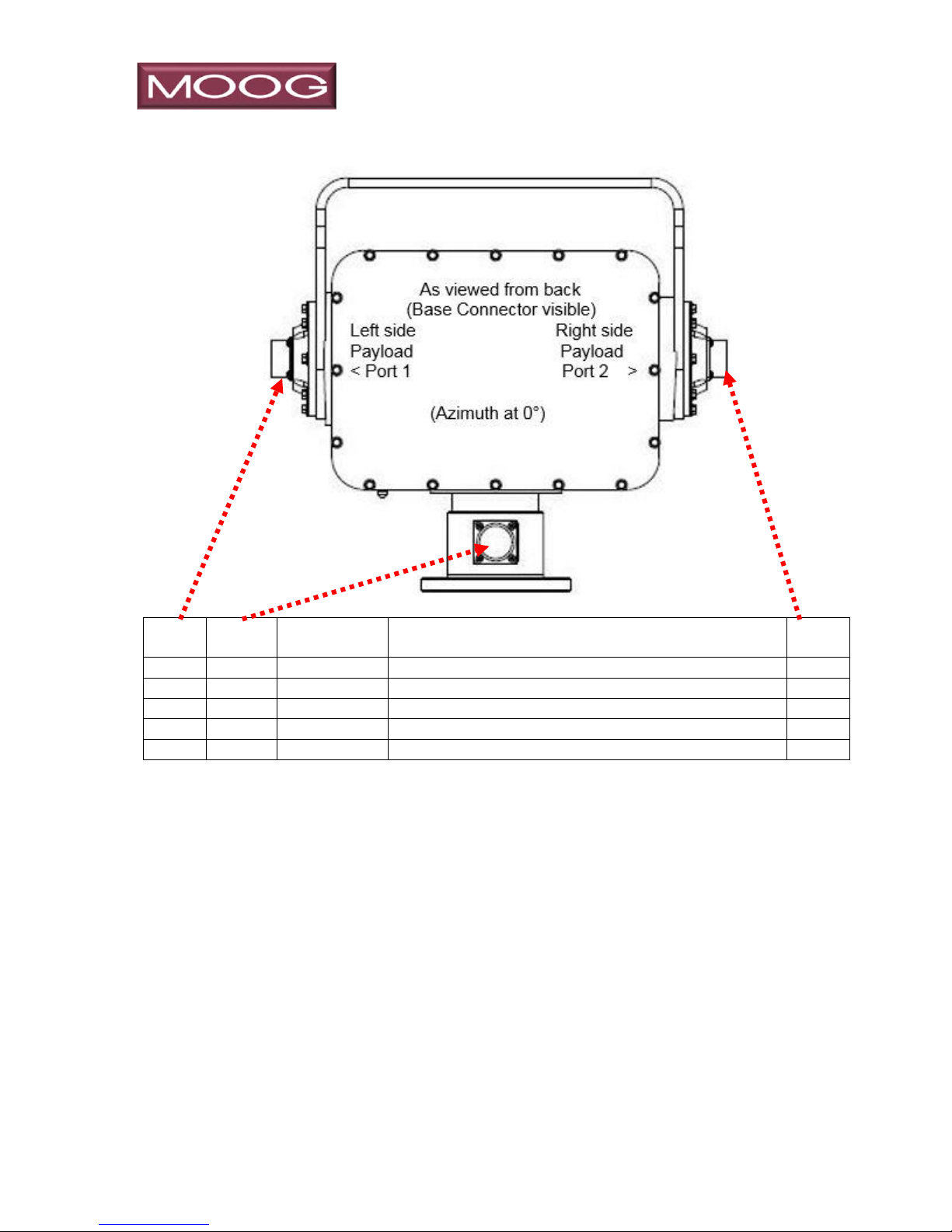
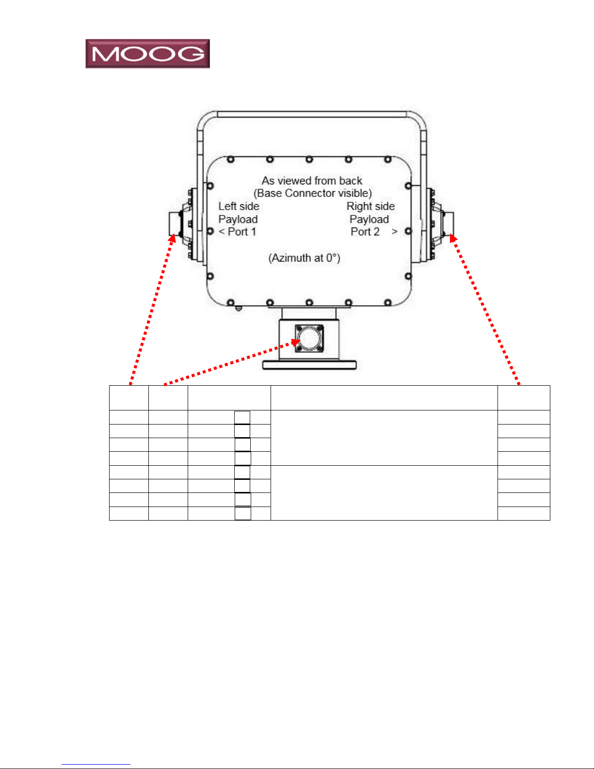
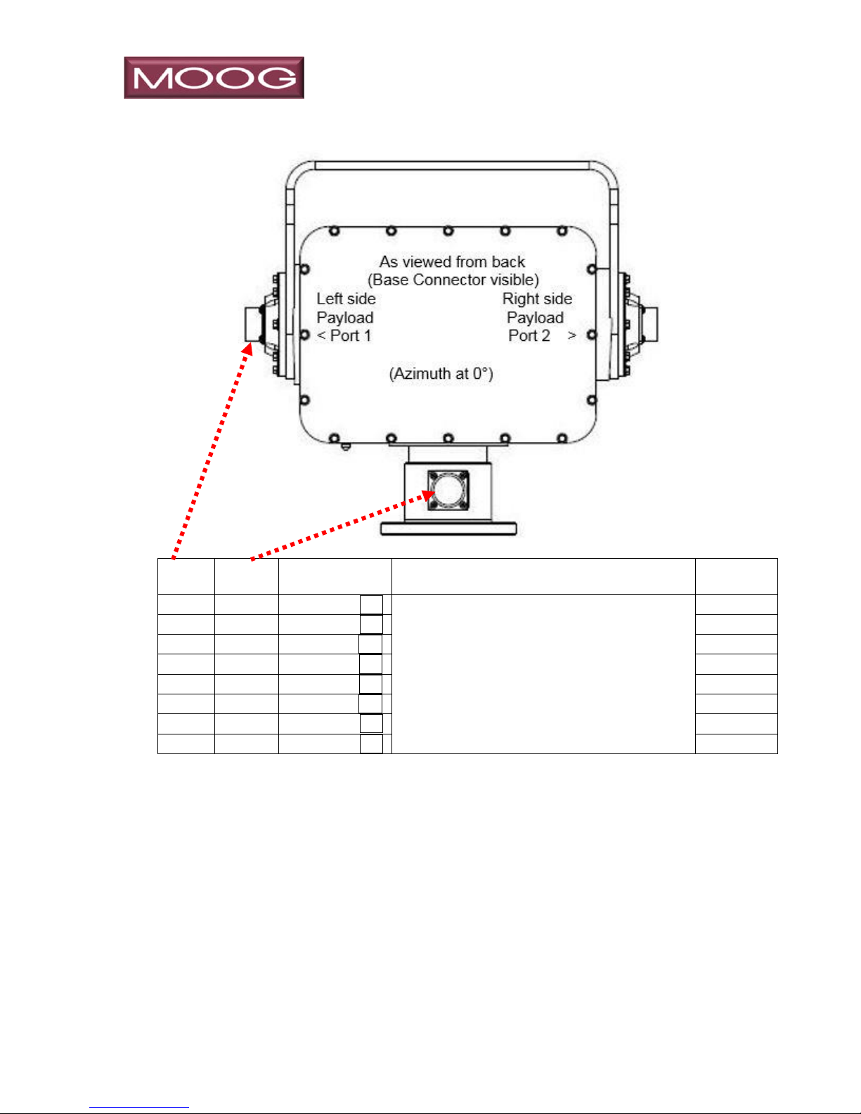
MPT models are designed to have the maximum amount of features and flexibility in
connectivity based on our experience in remote controlled positioners. The MPTs
feature two “Payload Port” connectors (one per side) that allow the user to wire their
payloads to the positioner providing multiple power and control options.
All models provide the following conductivity to EACH of the payload ports:
Four 8-Amp conductors designed for power (up to 210 VDC, 240 VAC) to the
payloads. These conductors are shared between the two payload ports and
the base connector
Two analog (±12 VDC) variable speed drivers designed to drive Zoom and
Focus motors, but may be used for other devices such as low power motors
or lighting.
Two analog inputs, designed to read position potentiometers for Z/F lenses.
These are useful when combining with stored positions to assure consistent
camera framing of objects of interest.
One Auxiliary power source, configurable for 12 or 24 VDC, with on/off
switchable control
One Auxiliary power source, configurable for 5 or 12 VDC, with on/off
switchable control
Three serial ports, providing single ended (RS232) or differential (RS422)
communication between payloads.
Additionally, there are IP and Video signal paths between the base connector
and the payload port. In continuous rotation models, these signals pass through
the integrated slip ring, which creates limitations to the number of signals and
bandwidth that can pass through. The non-continuous rotation model (8PA166) does not have these limitation, and therefore has the higher bandpass
GigE and HD-SDI video connections on each payload port.
Each 10/100 IP signal path requires four conductors, while a GigE IP signal
path requires eight conductors. HD-SDI video requires different wiring and a
higher caliber of slip ring than conventional analog EIA - RS170 video, but not
all budgets can accommodate the higher cost of the HD-SDI slip ring.
For these reasons, several models have been created in various configurations,
and the table below shows the comparisons:
_______________________________________________________________________
MN0090-05 Page 13 of 68 18008
MPT-90 PRODUCT MANUAL This document contains U.S. export controlled technical data as regulated by the U.S. Export Administration Regulations 15 CFR Parts 730-774, export, disclosure or transfer contrary to U.S. law is prohibited.
Page 14

____________________________________________________________________
Figure 4: Feature Comparison Table
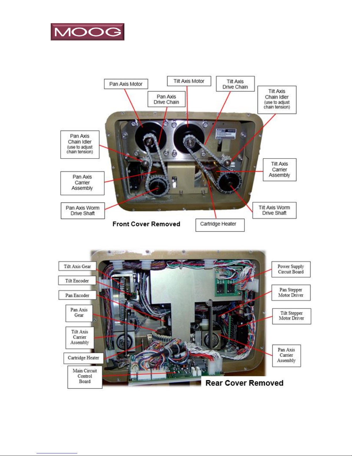
3.1 Pan and Tilt Description
The Pan & Tilt Unit is constructed of aluminum with stainless steel hardware.
The Pan & Tilt Housing (with Access Covers to provide access to the interior)
encloses the Pan & Tilt Motors, Chain & Gear Drive Assemblies, user settable
Limit Rings (hard stops), position encoders, and the main Control Circuit
Board which has multiple configurable options. Please refer to Figure 5 below
for component identification.
_______________________________________________________________________
MN0090-05 Page 14 of 68 18008
MPT-90 PRODUCT MANUAL This document contains U.S. export controlled technical data as regulated by the U.S. Export Administration Regulations 15 CFR Parts 730-774, export, disclosure or transfer contrary to U.S. law is prohibited.
Page 15
____________________________________________________________________
Figure 5: Pan & Tilt Unit Major Components
MPT-90 Wiring Signal Description
3.1.1 System Input Power – All Models
_______________________________________________________________________
MN0090-05 Page 15 of 68 18008
MPT-90 PRODUCT MANUAL This document contains U.S. export controlled technical data as regulated by the U.S. Export Administration Regulations 15 CFR Parts 730-774, export, disclosure or transfer contrary to U.S. law is prohibited.
Page 16
____________________________________________________________________
CAUTION
DO NOT CONNECT TO VOLTAGES HIGHER THAN
28 VDC WITHOUT RECONFIGURING.
Pin #
Signal
Description
45 & 52
System Power
+ (Positive)
Pins 45 & 52 supply positive (+) power to the P&T positioner, as well as
controlled payload power features and heaters. Due to the size of the
contacts, two pins are necessary; connect together external to the
positioner. Power should be between 24 to 28 VDC, and we recommend
an external 15A fuse.
50 & 51
System Power
– (Negative)
Pins 50 & 51 connect return (-) power from the P&T positioner, as well as
controlled payload power and heaters. Due to the size of the contacts, two
pins are necessary; connect together external of the positioner. Power
should be between 24 to 28 VDC. Note this is insulated from chassis
ground, but may be connected to chassis ground external to the positioner
if desired.
53
Chassis GND
Chassis Ground – isolated from power
The positioner is powered by 24-28 VDC, although it may be reconfigured for 28-48
VDC. It is highly recommended that you fuse the + power supply. Verify correct
polarity before applying power. The power of the system is isolated from chassis.
_______________________________________________________________________
MN0090-05 Page 16 of 68 18008
MPT-90 PRODUCT MANUAL This document contains U.S. export controlled technical data as regulated by the U.S. Export Administration Regulations 15 CFR Parts 730-774, export, disclosure or transfer contrary to U.S. law is prohibited.
Page 17
____________________________________________________________________
Pin #
Serial Control
Description
10
Serial Tx+ (TXD)
RS422/485 (or RS232) transmit (configurable)
33
Serial Tx-
RS422/485 transmit
11
Serial Rx+ (RXD)
RS422/485 (or RS232) receive (configurable)
34
Serial Rx-
RS422/485 receive
12
Signal ground
RS422/232, connected to system power negative, isolated from chassis.
Pin #
IP Control
Description
14
TX+_D1 ██
10/100 IP Control White/Orange T568B, typical RJ45 connector
36
TX-_D1 ██
15
RX+_D2 ██
10/100 IP Control White/Green T568B, typical RJ45 connector
37
RX-_D2 ██
10/100 IP Control Green T568B, typical RJ45 connector
3.1.2 IP and Serial Control of Positioner – All Models
Above communication ports may be used for control and settings of positioner and/or
payloads ports. Differential serial communication may be set to full or half duplex,
configurable in settings.
Communication to from base connector to payload ports is supported (see protocol
document).
“Transmit” and “Receive” are from the perspective of the positioner (DCE). Colors
shown for IP signals per EIA/TIA 568B are to aid or reference external wiring to the ports
and do not represent actual color of conductors inside the positioner.
_______________________________________________________________________
MN0090-05 Page 17 of 68 18008
MPT-90 PRODUCT MANUAL This document contains U.S. export controlled technical data as regulated by the U.S. Export Administration Regulations 15 CFR Parts 730-774, export, disclosure or transfer contrary to U.S. law is prohibited.
Page 18
____________________________________________________________________
Pin #
Serial Control
Description
Pin #
16
Serial Tx+ (TXD)
RS422/485 (or RS232) transmit (software configurable)
n/c
33
Serial Tx-
RS422/485 transmit
n/c
11
Serial Rx+ (RXD)
RS422/485 (or RS232) receive (configurable)
n/c
34
Serial Rx-
RS422/485 receive
n/c
12
Signal ground
Serial signal ground, connected to system power negative,
isolated from chassis.
n/c
n/c
Serial Tx+ (TXD)
RS422/485 (or RS232) transmit (software configurable)
16
n/c
Serial Tx-
RS422/485 transmit
33
n/c
Serial Rx+ (RXD)
11
n/c
Serial Rx-
RS422/485 receive
34
n/c
Signal ground
Serial signal ground, connected to system power negative,
isolated from chassis.
12
3.1.3 Additional Serial Control of Positioner – All Models
Additional serial communication ports are provided that allow payload devices to
control the positioner. An example of this may be a camera assembly equipped with
a video encoder.
“Transmit” and “Receive” are from the perspective of the positioner (DCE).
_______________________________________________________________________
MN0090-05 Page 18 of 68 18008
MPT-90 PRODUCT MANUAL This document contains U.S. export controlled technical data as regulated by the U.S. Export Administration Regulations 15 CFR Parts 730-774, export, disclosure or transfer contrary to U.S. law is prohibited.
Page 19
____________________________________________________________________
Left
Pins
Base
Pins
Signal
Description
Right
Pins
46
46
General I/O
User supplied power to payloads. 8A max.
46
47
47
General I/O
User supplied power to payloads. 8A max.
47
48
48
General I/O
User supplied power to payloads. 8A max.
48
49
49
General I/O
User supplied power to payloads. 8A max.
49
53
53
Chassis GND
Chassis Ground.
53
3.1.4 General Purpose I/O Pass Through & Chassis Ground All Models
The General Purpose I/O conductors are typically used for powering devices connected
to Port 1 and/or Port 2. The conductor connected to pins 46 are twisted together with the
conductor connected to pins 49, likewise 47 & 48 are paired. These are conductors
through the slip ring on continuous models, allowing high current (up to 8A continuously)
connections to the payload. Both left and right side ports are connected to the base
allowing a single user supplied power supply to power loads on both sides, assuming
they are of the same voltage. The maximum continuous current rating through the slip
ring is 8 amps, meaning the sum of both the left and right side through any one conductor
is not to exceed 8A. The slip ring is rated up to 210VDC, and may be used for AC current
with a 500 VRMS dielectric strength in all combinations. Chassis Ground is internally
connected to the mechanical chassis of the positioner, and is available on all three
connectors. Chassis ground is not internally connected to any of the General Purpose
I/O ports, but may be connected externally if desired.
_______________________________________________________________________
MN0090-05 Page 19 of 68 18008
MPT-90 PRODUCT MANUAL This document contains U.S. export controlled technical data as regulated by the U.S. Export Administration Regulations 15 CFR Parts 730-774, export, disclosure or transfer contrary to U.S. law is prohibited.
Page 20
____________________________________________________________________
Left
Pins
Base
Pins
Signal
T-568B
Description
Right
Pins
2
2
TX+_D1 ██
Ethernet User 10/100 “A” to port 1
n/c
26
26
TX-_D1 ██
n/c
3
3
RX+_D2 ██
n/c
27
27
RX-_D2 ██
n/c
n/c
20
TX+_D1 ██
Ethernet User 10/100 “C” to port 2
2
n/c
41
TX-_D1 ██
26
n/c
21
RX+_D2 ██
3
n/c
42
RX-_D2 ██
27
3.1.5 Model 8-PB133, 10/100 Ethernet Ports 1 & 2
Typical 10/100 Ethernet connections require 2 sets of Twisted Pair (TP) conductors,
4 conductors total. Gig-E Ethernet connections require 4 sets of TP, a total of 8
conductors. Due to limitations of the conductor availability in the slip ring, the MPT
series allocates 8 conductors between the base connector and the payload ports.
Therefore, these conductors may be configured as two 10/100 Ethernet ports, one
to each side (Model 8-PB133 depicted above) or as a single Gig-E signal path to
either side (See next two pages).
Colors shown for IP signals per EIA/TIA 568B are to aid or reference external wiring
to the ports and do not represent actual color of conductors inside the positioner.
_______________________________________________________________________
MN0090-05 Page 20 of 68 18008
MPT-90 PRODUCT MANUAL This document contains U.S. export controlled technical data as regulated by the U.S. Export Administration Regulations 15 CFR Parts 730-774, export, disclosure or transfer contrary to U.S. law is prohibited.
Page 21
____________________________________________________________________
Left
Pins
Base
Pins
Signal
T-568B
Description
Right Pins
2
2
BI_DA+ ██
Ethernet User GigE Base to port 1
n/c
26
26
BI_DA- ██
n/c
3
3
BI_DB+ ██
n/c
27
27
BI_DB- ██
n/c 4 4
BI_DC- ██
n/c
28
28
BI_DC+ ██
n/c 5 5
BI_DD+ ██
n/c
29
29
BI_DD- ██
n/c
3.1.6 Model 8-PB151, Gigabit Ethernet Base to Port 1 Payload
Gig-E Ethernet connections require 4 sets of TP, a total of 8 conductors, so in this
configuration there is a single GigE provision wired to Port 1.
Colors shown for IP signals per EIA/TIA 568B are to aid or reference external wiring
to the ports and do not represent actual color of conductors inside the positioner.
_______________________________________________________________________
MN0090-05 Page 21 of 68 18008
MPT-90 PRODUCT MANUAL This document contains U.S. export controlled technical data as regulated by the U.S. Export Administration Regulations 15 CFR Parts 730-774, export, disclosure or transfer contrary to U.S. law is prohibited.
Page 22

____________________________________________________________________
Left
Pins
Signal
Description
Right
Pins
10
Serial Tx+ (Txd)
<Payload 1 control (Left) Payload 2 control (Right)>
10
33
Serial Tx-
<Payload 1 control (Left) Payload 2 control (Right)>
33
11
Serial Rx+ (Rxd)
<Payload 1 control (Left) Payload 2 control (Right)>
11
34
Serial Rx-
<Payload 1 control (Left) Payload 2 control (Right)>
34
12
Signal ground
<Payload 1 control (Left) Payload 2 control (Right)>
12
7
Serial Tx+ (Txd)
<Payload 3 control (Left) Payload 4 control (Right)>
7
31
Serial Tx-
<Payload 3 control (Left) Payload 4 control (Right)>
31
8
Serial Rx+ (Rxd)
<Payload 3 control (Left) Payload 4 control (Right)>
8
32
Serial Rx-
<Payload 3 control (Left) Payload 4 control (Right)>
32
13
Signal ground
<Payload 3 control (Left) Payload 4 control (Right)>
13
3.1.7 Serial Control Communication to ports
These connections connect the control from Moog Main Controller to the payloads.
This provides a method of communicating from the system control signal path to the
payloads via the 62H command as found in the protocol document. The serial ports
may be user configurable as either single ended (RS232) or differential (RS422). All
signal ground wires are connected to the systems negative input power supply.
_______________________________________________________________________
MN0090-05 Page 22 of 68 18008
MPT-90 PRODUCT MANUAL This document contains U.S. export controlled technical data as regulated by the U.S. Export Administration Regulations 15 CFR Parts 730-774, export, disclosure or transfer contrary to U.S. law is prohibited.
Page 23

____________________________________________________________________
Left
Pins
Signal Name
Description
Signal Name
Right
Pins
20
Zoom + (Cam1)
PWM motor drive pair
designed for Zoom Lens Drive
Zoom + (Cam 2)
20
41
Zoom – (Cam 1)
Zoom – (Cam 2)
41
21
Focus + (Cam 1)
PWM motor drive pair
designed for Focus Lens Drive
Focus + (Cam 2)
21
43
Focus – (Cam 1)
Focus – (Cam 2)
43
22
Z/F +3VDC
V source for position feedback
Z/F +3 VDC
22
44
Z/F ground
Return for position feedback
Z/F ground
44
23
Z Position Sense (Cam 1)
Connect to Z position pot wiper
Z Position Sense (Cam 2)
23
44
F Position Sense (Cam 1)
Connect to F position pot wiper
F Position Sense (Cam 2)
44
3.1.8 Camera Lens Accommodations
The positioner controller provides four proportionally controlled, bi-directional PWM
motor drivers suited to drive camera lenses with motorized zoom and focus. Most
of these style lenses also have potentiometers incorporated to provide a relative
sensing of the Z & F position. Use of the Z & F motor drivers with the potentiometer
position feedback to allow stored presets that encompass Az, El, Z & F for easy
camera integration.
Zoom motors should be connected to the Zoom + & Zoom - pins, while Focus
motors should be connected to the Focus + & Focus – pins. Position feedback
potentiometers are typically used as voltage dividers, with the supply voltage (Z/F
+3VDC & Z/F ground) connected across the two potentiometers. The
potentiometers wipers should be connected to the Zoom Position Sense and Focus
Position Sense respectfully.
_______________________________________________________________________
MN0090-05 Page 23 of 68 18008
MPT-90 PRODUCT MANUAL This document contains U.S. export controlled technical data as regulated by the U.S. Export Administration Regulations 15 CFR Parts 730-774, export, disclosure or transfer contrary to U.S. law is prohibited.
Page 24

____________________________________________________________________
Left
Pins
Base
Pins
Description
Right Pins
25
25
Video 1 coaxial
n/c
n/c
30
Video 2 coaxial
30
3.1.9 Video Signal
Signal paths suitable for video run from each of the port connectors (one per
side) to the base. These are suitable for RS170 video signals.
Special connector pins compatible with standard RG179 75Ω coaxial cable
are in the package with the included base and port connectors.
_______________________________________________________________________
MN0090-05 Page 24 of 68 18008
MPT-90 PRODUCT MANUAL This document contains U.S. export controlled technical data as regulated by the U.S. Export Administration Regulations 15 CFR Parts 730-774, export, disclosure or transfer contrary to U.S. law is prohibited.
Page 25

____________________________________________________________________
CAUTION
DO NOT CONNECT TO VOLTAGES HIGHER
THAN 28 VDC WITHOUT RECONFIGURING.
3.2 Moog Pan and Tilt Control Circuit Board Description
Power and communication to control the P&T is provided through the 53-Pin base
connector. The Moog Pan & Tilt microprocessor / circuit control board processes all
communication, position information, and presents it through the communication
buss via the Protocol. The system may be controlled either by a serial or IP
connection.
Power supplied is a minimum 24 VDC providing power to the Control Circuit Board
to control the two (2) stepper motors drivers (1 for Pan Axis and 1 for Tilt Axis), as
well as regulated and unregulated power to the side mounted payload ports. Note
the Positioner may be supplied higher voltages for extended performance if
configured to do so on the Control Circuit Board. DO NOT APPLY MORE THAN 28
VDC to the unit without first configuring the PCB to accept higher voltage.
The Control communication is processed on the control circuit board providing
control and status information on the communication buss. Also connected to main
controller are two incremental position encoders, an optical encoder is used of the
Pan Axis motion and a magnetic encoder is used for the Tilt Axis motion.
The Control Circuit Board is attached vertically to the inside of the Pan & Tilt Housing
and can be accessed by removing the Rear Access Cover. The Control Circuit Board
must be accessed to configure P&T input voltage selection, voltage selection and
method of communication to the payload ports.
The Control Circuit Board has a number of switches and jumpers to allow various
configurations of power and communication options. The following section outlines
PCB configuration to allow various configurations.
3.2.1 Control Circuit Board Configuration
3.2.1.1 Circuit Card Access
1. Remove the sixteen 5/16” hex head bolts holding the rear cover. Place the
cover aside, assuring not to damage the O-Ring gasket, mating surface or
paint. Locate the Ethernet cable on the left side of the board and release the
cable from the connector port. Refer to Figure 6.
_______________________________________________________________________
MN0090-05 Page 25 of 68 18008
MPT-90 PRODUCT MANUAL This document contains U.S. export controlled technical data as regulated by the U.S. Export Administration Regulations 15 CFR Parts 730-774, export, disclosure or transfer contrary to U.S. law is prohibited.
Page 26

____________________________________________________________________
Ethern et Cable
Main Circuit Board
Figure 6: Accessing the Circuit Board
2. Loosen the two #1 Philips head screws at the top of the board; these screws
are retained with a small O-Ring between the PCB and the bracket; turn only
enough to release the bracket. You may need to pull the bracket outward to
allow the board to swing downward. Refer to Figure 7 below.
Figure 7: Circuit Board
3. The PCB has multiple switches and jumpers providing options that are used
for customer configuration. The options are:
Setting input voltage range
Communication settings for primary control of the MPT-90
Communication settings for secondary control of the MPT-90
Communication settings for Payload control
Voltage settings for Port Payload power
Voltage and high-side/low-side switching of Auxiliary Port power
Refer to Figures 7 and 8.
_______________________________________________________________________
MN0090-05 Page 26 of 68 18008
MPT-90 PRODUCT MANUAL This document contains U.S. export controlled technical data as regulated by the U.S. Export Administration Regulations 15 CFR Parts 730-774, export, disclosure or transfer contrary to U.S. law is prohibited.
Page 27

____________________________________________________________________
Figure 8: Circuit Board Components I
_______________________________________________________________________
MN0090-05 Page 27 of 68 18008
MPT-90 PRODUCT MANUAL This document contains U.S. export controlled technical data as regulated by the U.S. Export Administration Regulations 15 CFR Parts 730-774, export, disclosure or transfer contrary to U.S. law is prohibited.
Page 28

____________________________________________________________________
COMM SERIAL
SETTINGS S2
Figure 9: Circuit Board Components II
_______________________________________________________________________
MN0090-05 Page 28 of 68 18008
MPT-90 PRODUCT MANUAL This document contains U.S. export controlled technical data as regulated by the U.S. Export Administration Regulations 15 CFR Parts 730-774, export, disclosure or transfer contrary to U.S. law is prohibited.
Page 29

____________________________________________________________________
Jumper P1, shown
without jumper for clarity
Dot indicates pin 1
3.2.1.2 PBC Jumper Settings:
NOTE
All jumper settings, the screened dot is Pin 1. Refer to Figure 10 below.
3.2.1.2.1 P1 Input Power:
The positioner requires 24 to 28 VDC to operate, with positive current applied
to pins 45 & 52 and power return through pins 50 & 51 of the base connector.
Note that due to current limitations of the pins in the base connector, the user
must apply power to both pairs of pins to assure proper operation. In the event
that two separate power supplies are used, you must connect the two negative
wires (pins 50 & 51) together.
Figure 10: Jumper Locations
The MPT product may be configured to operate on 28-70 VDC by changing
the PCB P1 jumper setting. To reconfigure to operation on voltages higher
than 28 VDC, you must move the jumper on P1 (located in the upper right
corner of the Moog Controller PCB) from the default position of 1-2 to the 2-3
position. The dot screened on the PCB indicates pin 1.
NOTE
The 24 VDC is passed to the payload ports, and is not regulated if the input
power is in the default configuration. If the P&T is configured for higher
voltage usage, the 24 VDC payload power is regulated.
_______________________________________________________________________
MN0090-05 Page 29 of 68 18008
MPT-90 PRODUCT MANUAL This document contains U.S. export controlled technical data as regulated by the U.S. Export Administration Regulations 15 CFR Parts 730-774, export, disclosure or transfer contrary to U.S. law is prohibited.
Page 30

____________________________________________________________________
3.2.1.2.2 P45
P45 is used to select the voltage available on “Aux1 Power” (pin 36 on
Payload Port 1). In the default mode with the jumper on pins 1-2, pin 36 of
Payload Port 1 will have the P&T source voltage (*typically +24 VDC)
available with respect to pin 14. Moving the jumper to pins 2-3 will reduce
this to +12 VDC regulated.
3.2.1.2.3 P48
P48 is used to select the voltage available on “Aux2 Power” (pin 37 on
Payload Port 1). In the default mode with the jumper on pins 1-2, pin 37 of
Payload Port 1 will have the P&T source voltage (*typically +24 VDC)
available with respect to pin 15. Moving the jumper to pins 2-3 will reduce
this to +12 VDC regulated.
3.2.1.2.4 P57
P57 is used to select the voltage available on “Payload 3 (pin 45 of Payload
Port 1). In the default mode with the jumper on pins 1-2, pin 45 of Payload
Port 1 will have +12 VDC regulated power available with respect to pin 50.
Moving the jumper to pins 2-3 will reduce this to +5 VDC regulated.
_______________________________________________________________________
MN0090-05 Page 30 of 68 18008
MPT-90 PRODUCT MANUAL This document contains U.S. export controlled technical data as regulated by the U.S. Export Administration Regulations 15 CFR Parts 730-774, export, disclosure or transfer contrary to U.S. law is prohibited.
Page 31

____________________________________________________________________
3.2.1.2.5 P59
P59 is used to select the voltage available on “Payload 4 (pin 45 of Payload
Port 2). In the default mode with the jumper on pins 1-2, pin 45 of Payload
Port 2 will have +12 VDC regulated power available with respect to pin 50.
Moving the jumper to pins 2-3 will reduce this to +5 VDC regulated.
3.2.1.2.6 P53
P53 is used to reconfigure how Aux 3 (Pins 36 & 14 of Payload 2) power
switching works. In the default mode, the + supply voltage (Pin 36, 12 or 5
VDC configurable) may be switched ON/OFF by the controller.
Reconfiguring P53 allows the – return side (pin 14) to be switched in an “open
collector” configuration. Although useful in some applications, do not use this
if your payload is otherwise connected back to ground.
3.2.1.2.7 P56
P56 is used to reconfigure how Aux 4 (Pins 37 & 15 of Payload 2) power
switching works. In the default mode, the + supply voltage (Pin 37, 12 or 5
VDC configurable) may be switched ON/OFF by the controller.
Reconfiguring P53 allows the – return side (pin 15) to be switched in an “open
collector” configuration. Although useful in some applications, do not use this
if your payload is otherwise connected back to ground.
_______________________________________________________________________
MN0090-05 Page 31 of 68 18008
MPT-90 PRODUCT MANUAL This document contains U.S. export controlled technical data as regulated by the U.S. Export Administration Regulations 15 CFR Parts 730-774, export, disclosure or transfer contrary to U.S. law is prohibited.
Page 32

____________________________________________________________________
3.3 PCB Switch Settings
The PCB has two user configurable eight position switches (Figure 11, S2,
S4) used to configure the serial communication ports. These ports are
typically used to control the positioner, or the payloads attached to the
positioner.
Figure 11: PCB Switches
3.3.1 S2 switch settings for serial communication ports
S2 configures the user control serial ports on the base and payload ports. Set
for the desired serial communication mode. Note that in RS485 mode,
termination should be ON for the last unit in the chain.
BASE PAYLOAD PAYLOAD
CONNECTOR PORT 1 PORT2
RS422 RS232 PINS PINS PINS
Serial Tx+ (TXD) 10 16 16
Serial Tx- 33 38 38
Serial Rx+ (RXD) 11 17 17
Serial Rx- 34 39 39
Signal Ground (Gnd) 12 18 18
_______________________________________________________________________
MN0090-05 Page 32 of 68 18008
MPT-90 PRODUCT MANUAL This document contains U.S. export controlled technical data as regulated by the U.S. Export Administration Regulations 15 CFR Parts 730-774, export, disclosure or transfer contrary to U.S. law is prohibited.
Page 33

____________________________________________________________________
The first three switch positions on S2 configure the serial connection on the
base connector pins in the table above.
S2 switch setting for RS232 at base S2 switch setting for RS 422 at base
S2 switch setting for RS-485 4-wire at base S2 switch setting for RS-485 2-wire at base
The last 3 switch positions on S2 configured the serial connection on Port 1 pins in
the table above:
S2 switch setting for RS232 at port 1 S2 switch setting for RS 422 at port 1
S2 switch setting for RS485 4-wire S2 switch setting for RS485 2-wire
at port 1 at port 1
Switch position 4 should be in the “ON” position to enable the serial connection on
Port 2 pins in the table above. Note that this port may be configured for RS232 or
RS422 via software.
_______________________________________________________________________
MN0090-05 Page 33 of 68 18008
MPT-90 PRODUCT MANUAL This document contains U.S. export controlled technical data as regulated by the U.S. Export Administration Regulations 15 CFR Parts 730-774, export, disclosure or transfer contrary to U.S. law is prohibited.
Page 34

____________________________________________________________________
S4 Switch setting for RS232 at Port 1 S4 Switch setting
S4 Switch setting for RS422 at Port 1 S4 Switch
S2 switch setting to enable port 2 serial.
3.3.2 S4 switch settings for serial communication ports
S4 configures additional serial connections at the payload ports. Set for the desired
serial communication mode. Note that in RS485 mode, termination should be ON
for the last unit in the chain.
PAYLOAD PAYLOAD
PORT 1 PORT 2
RS422 RS232 PINS PINS
Serial Tx+ (TXD) 10 10
Serial Tx- 33 33
Serial Rx+ (RXD) 11 11
Serial Rx- 34 34
Signal Ground Gnd 12 12
_______________________________________________________________________
MN0090-05 Page 34 of 68 18008
MPT-90 PRODUCT MANUAL This document contains U.S. export controlled technical data as regulated by the U.S. Export Administration Regulations 15 CFR Parts 730-774, export, disclosure or transfer contrary to U.S. law is prohibited.
Page 35

____________________________________________________________________
CAUTION
TWO PEOPLE ARE REQUIRED TO MOVE OR LIFT THE
MPT-90, DROPPING IT COULD DAMAGE THE MPT-90
WARNING
THE MPT-90 PRODUCES SIGNIFICANT TORQUE IN BOTH
THE PAN AND TILT MODES THAT CAN CAUSE INJURY IF
YOU ATTEMPT TO STOP IT WITH YOUR HANDS OR BODY
WARNING
DO NOT MOUNT THE MPT-90 (MOBILE OR STATIONARY)
SUCH THAT IT WILL CONTACT POWER LINES. IF THE
MPT-90 DOES CONTACT POWER LINES IT COULD
INJURE THE INSTALLER OR DAMAGE THE MPT-90.
4.0 INSTALLATION
4.1 Unpack and Inspect
Carefully unpack and examine the MPT-90 for signs of physical damage,
particularly dented or broken parts, damage to wire harness, distortion of the
tilt table or covers. If any signs of damage are observed, notify the freight
carrier immediately for a claim. Retain all of the packaging material.
4.2 Quick Start Guide
Upon opening the box containing the MPT-90 refer to the Moog Quick
Start Guide (CC36600) for instructions and for the MPT-90 packing list.
NOTE
One Test Cable, part number CC36117-6 is included in each shipment
regardless of the number of MPT-90 assemblies shipped. It is not
recommended that the Moog supplied test cable be used for a permanent
installation. The test cable should be retained for bench setup and
troubleshooting should it become necessary.
4.3 Installation Procedures - Mechanical
4.3.1 Site Location
Select a mounting location that will provide the desired maximum movement
of the Pan & Tilt angles without coming in contact with or striking any objects
in their sweep paths.
NOTE
An arrow on the side of the Pan & Tilt indicates the direction the front of
the unit is facing.
_______________________________________________________________________
MN0090-05 Page 35 of 68 18008
MPT-90 PRODUCT MANUAL This document contains U.S. export controlled technical data as regulated by the U.S. Export Administration Regulations 15 CFR Parts 730-774, export, disclosure or transfer contrary to U.S. law is prohibited.
Page 36

____________________________________________________________________
Limit Rings (Hard Stops) are provided to limit the degree of travel in the tilt
path. The pan travel is continuous and the tilt travel can be narrowed from
the maximum of 180° (±90° from horizon) to a lesser value.
4.3.2 Caution on Mobile Mounting
When using a Pan & Tilt in mobile applications, transporting an unsupported
system payload can cause mechanical overloading due to the shock and
vibration associated with movement over normal road surfaces.
These forces can be amplified further if travelling off-road, or if the positioner
system is mounted on a moveable platform such as a boom arm or telescopic
mast. In certain conditions, these dynamic forces added to the normal P&T
payload can have a cumulative effect and ultimately cause structural failure of
the positioner.
When designing transportable systems, make sure the payload is secured
during transit to assure that shock and vibration is not transmitted to the tilt
arm or table top by an unsupported load.
_______________________________________________________________________
MN0090-05 Page 36 of 68 18008
MPT-90 PRODUCT MANUAL This document contains U.S. export controlled technical data as regulated by the U.S. Export Administration Regulations 15 CFR Parts 730-774, export, disclosure or transfer contrary to U.S. law is prohibited.
Page 37

____________________________________________________________________
4.3.3 MPT-90 Installation
The Mounting Base (6.0” diameter) is drilled with six (6) .39” diameter
mounting holes on a 5.0” diameter bolt circle. Using the mounting holes,
fasten the base to a stable platform using (recommended) 5/16” high strength
stainless steel bolts, washers, and nuts. Refer to Figure 12.
NOTE
Consideration of wind and ice load factors on the Pan & Tilt Unit, and its
payload, are important when calculating how solid the mounting platform
has to be and the strength required by the mounting bolts.
Figure 12: Mounting Base
1. Place the MPT-90 on the mounting surface. Align the base connector with
the back of the mounting surface and make sure that the pan and tilt is
pointing in the correct direction.
2. Using an alternating pattern insert six (6) 5/16” high strength stainless steel
bolts through the MPT-90 mounting base and mounting surface.
3. Install six (6) washers and nuts on the bolts
4. Torque the nuts to 18-23 ft. lbs.
_______________________________________________________________________
MN0090-05 Page 37 of 68 18008
MPT-90 PRODUCT MANUAL This document contains U.S. export controlled technical data as regulated by the U.S. Export Administration Regulations 15 CFR Parts 730-774, export, disclosure or transfer contrary to U.S. law is prohibited.
Page 38

____________________________________________________________________
CAUTION
CORRECT INSTALLATION OF THE INTERCONNECTING
CABLE TO THE BASE CONNECTOR BETWEEN THE
CONTROLLER AND THE PAN AND TILT UNIT IS REQUIRED
FOR RELIABLE OPERATION OF THE POSITIONING
SYSTEM. CABLES SHOULD BE CONSTRUCTED WITH
CONSIDERATION OF WEATHER CONDITIONS, AND
SEALED AS REQUIRED TO ASSURE TROUBLEFREE
SERVICE. MOOG IS NOT RESPONSIBLE FOR POSITIONER
DAMAGE DUE TO FAULTY CABLING.
4.4 Installation Procedures – Electrical
4.4.1 Connector installation
Included with the positioner are mating plugs and contacts for the base and two side
port connectors. Follow the instructions below to build cables for the installation;
additional instructions may be included with the contacts.
_______________________________________________________________________
MN0090-05 Page 38 of 68 18008
MPT-90 PRODUCT MANUAL This document contains U.S. export controlled technical data as regulated by the U.S. Export Administration Regulations 15 CFR Parts 730-774, export, disclosure or transfer contrary to U.S. law is prohibited.
Page 39

____________________________________________________________________
_______________________________________________________________________
MN0090-05 Page 39 of 68 18008
MPT-90 PRODUCT MANUAL This document contains U.S. export controlled technical data as regulated by the U.S. Export Administration Regulations 15 CFR Parts 730-774, export, disclosure or transfer contrary to U.S. law is prohibited.
Page 40

____________________________________________________________________
4.5 MATING RECEPTACLE CONNECTOR WIRING
The following charts show the signals connected to the various
pins/conductors on the positioner’s connectors. Note that not all models or
variants use all connections, so check with your model number before
constructing wiring harnesses. You may choose to not to use some signals,
and therefore not make connections on your cables. It is recommended that
you use appropriate cabling sealing methods suitable for the environment of
use. This may include potting of the connector, or use of weather sealing
sheathing.
Fundamental power and operational communication is shown on the first
chart below:
_______________________________________________________________________
MN0090-05 Page 40 of 68 18008
MPT-90 PRODUCT MANUAL This document contains U.S. export controlled technical data as regulated by the U.S. Export Administration Regulations 15 CFR Parts 730-774, export, disclosure or transfer contrary to U.S. law is prohibited.
Page 41

____________________________________________________________________
_______________________________________________________________________
MN0090-05 Page 41 of 68 18008
MPT-90 PRODUCT MANUAL This document contains U.S. export controlled technical data as regulated by the U.S. Export Administration Regulations 15 CFR Parts 730-774, export, disclosure or transfer contrary to U.S. law is prohibited.
Page 42

____________________________________________________________________
_______________________________________________________________________
MN0090-05 Page 42 of 68 18008
MPT-90 PRODUCT MANUAL This document contains U.S. export controlled technical data as regulated by the U.S. Export Administration Regulations 15 CFR Parts 730-774, export, disclosure or transfer contrary to U.S. law is prohibited.
Page 43

____________________________________________________________________
CAUTION
PRIOR TO OPERATING THE PAN & TILT UNIT OR ACCESSING
THE INTERIOR, READ AND BECOME FAMILIAR WITH ALL OF
THE SAFETY RECOMMENDATIONS FOUND AT THE
BEGINNING OF THIS MANUAL AND ON ANY SAFETY DECAL
AFFIXED TO THE INSIDE OR OUTSIDE OF THE UNIT.
4.6 MPT-90 Setup and Adjustment procedures
Prior to operating the Pan & Tilt Unit, perform the following Setup &
Adjustment Procedures if necessary:
_______________________________________________________________________
MN0090-05 Page 43 of 68 18008
MPT-90 PRODUCT MANUAL This document contains U.S. export controlled technical data as regulated by the U.S. Export Administration Regulations 15 CFR Parts 730-774, export, disclosure or transfer contrary to U.S. law is prohibited.
Page 44

____________________________________________________________________
5.0 MOOG PTZ WEB INTERFACE INTERNAL WEB GUI
5.1 CONNECTING THE MPT-90 TO A COMPUTER
1) Connect the RJ45 connector labeled “Ethernet Com. to your computer
or Ethernet Switch
2) The MPT-90’s default IP address is 192.168.1.10. Make sure your
computer is on the same subnet; change your private IP address if
necessary.
3) Click or press the
Windows key on
your keyboard and type
“network connections”.
4) Right click on “Local Area Connection” and select “Properties” to open
Local Area Connection Properties. Note that in Windows 8 or 10
naming may be different, such as Ethernet.
_______________________________________________________________________
MN0090-05 Page 44 of 68 18008
MPT-90 PRODUCT MANUAL This document contains U.S. export controlled technical data as regulated by the U.S. Export Administration Regulations 15 CFR Parts 730-774, export, disclosure or transfer contrary to U.S. law is prohibited.
Page 45

____________________________________________________________________
5) Double click on “Internet Protocol Version
4 (TCP/IPv4) to open Internet Protocol
Version 4 (TCP/IPv4) Properties.
6) Within the Internet Protocol Version 4 (TCP/IPv4) Properties panel,
select “Use the following IP address:” and type in the following:
IP address 192.168.1.9 Subnet mask: 255.255.255.0
Default gateway 192.168.1.1 Click OK to save and exit.
7) Open a web browser and type in the IP address of the positioner
(192.168.1.10) into the web browser’s address bar.
NOTE:
Some versions of Microsoft Internet Explorer have issues rendering
HTML5 and will no open the page correctly. Use Google Chrome, or
Mozilla Firefox.
8) The positioner’s web interface should open.
_______________________________________________________________________
MN0090-05 Page 45 of 68 18008
MPT-90 PRODUCT MANUAL This document contains U.S. export controlled technical data as regulated by the U.S. Export Administration Regulations 15 CFR Parts 730-774, export, disclosure or transfer contrary to U.S. law is prohibited.
Page 46

____________________________________________________________________
5.2 CONNECTING THE MPT-90 TO A NETWORK
1) This method is useful if you do not know the IP address assigned to the
positioner.
2) On the Thumb Drive that included this manual is a software utility called
“TI Tiva Board Finder”. Install this software on a computer on the same
network as the positioner.
3) Launch the application (finder.exe) and the IP addresses of all the
positioners on the network will be shown.
4) Open a web browser and type in the IP address of the positioner you
want to connect to into the web browser’s address bar. NOTE: Some
versions of Microsoft Internet Explorer have issues rendering HTML5
and will no open the page correctly. Use Google Chrome, or Mozilla
Firefox.
_______________________________________________________________________
MN0090-05 Page 46 of 68 18008
MPT-90 PRODUCT MANUAL This document contains U.S. export controlled technical data as regulated by the U.S. Export Administration Regulations 15 CFR Parts 730-774, export, disclosure or transfer contrary to U.S. law is prohibited.
Page 47

____________________________________________________________________
5) The positioner’s web interface should open.
5.3 MOOG PTZ WEB INTERFACE
The Moog MPT-90 allows the user to connect and perform fundamental
functions and moves via an IP connection on a network. This is a quick
method to validate proper motion and primary functions.
NAVIGATION BAR - The Navigation Bar is used to select the page of the
Web GUI to select different Web pages. The Navigation Bar appears on all
pages and is used to move from one page to another.
PTZ CONTROL - The default page of the MOOG PTZ WEB INTERFACE is
the PTZ CONTROL page. Positioner movement, current position, setting
presets for both the positioner and payload can be accomplished using this
page.
PTZ CONTROL - The PTZ Control page is used to move the positioner.
_______________________________________________________________________
MN0090-05 Page 47 of 68 18008
MPT-90 PRODUCT MANUAL This document contains U.S. export controlled technical data as regulated by the U.S. Export Administration Regulations 15 CFR Parts 730-774, export, disclosure or transfer contrary to U.S. law is prohibited.
Page 48

____________________________________________________________________
CURRENT POSITION WINDOW: The Current Position window displays
the current position of the P&T in degrees relative to the “0” position. The
Zoom and Focus values represent relative values of the Zoom (pin 23 of
the payload ports) and Focus (pin 44 of the payload ports) designed for
Zoom & Focus potentiometers used in analog camera lenses. Note that
Zoom 1 & Focus 1 are for the Port 1 side and Zoom 2 & Focus 2 are for
the Port 2 side. See CAMERA LENS ACCOMODATIONS section.
JOG BUTTONS WINDOW: The Jog buttons allow you to move the P&T in
various directions. First, select the speed for the Pan and/or Tilt (move the
slider to the right for faster speeds), then press the direction button. The
up/down arrows in the box beneath the circular button are designed for
driving Zoom 1 & 2 and Focus 1 & 2 motors on lenses that may be
connected to ports 1 & 2 respectively. Zoom motors are to be connected
to pins 20 & 41, while Focus motors use pins 21 & 43. See CAMERA
LENS ACCOMODATIONS section.
MOVE TO POSITION – The Move to Position section allows the user to
direct enter a coordinate using a Pan (Azimuth) and Tilt (Elevation)
position and execute an automated move to the indicated position, by
pressing the “Move To Entered PT Position” button. Additionally, if you
have a Zoom and Focus lens attached to either payload port 1 or 2 (of
both) you may enter those desired positions and the analog motor drivers
will reposition the Z&F lens to the appropriate position; in this case, use the
_______________________________________________________________________
MN0090-05 Page 48 of 68 18008
MPT-90 PRODUCT MANUAL This document contains U.S. export controlled technical data as regulated by the U.S. Export Administration Regulations 15 CFR Parts 730-774, export, disclosure or transfer contrary to U.S. law is prohibited.
Page 49

____________________________________________________________________
“Move To Entered PT & ZF Positions” button. Pressing the “Move to
Home Position” drives the P&T to the position stored in preset 32.
Pressing the “Move to Zero Position” drives the P&T to the 0° pan, 0° tilt
position.
PTZ PRESETS – The PTZ Presets window allow the user to enter a
coordinate and store it as a preset, or save the current position as a
preset.
To store a coordinate as a preset, select the preset address (1 – 32) in
the Preset Number window, then enter the coordinate in the “Pan:” and
“Tilt:” windows. Then press “Save Preset Using Entered Position”. If you
have a Z&F lens connected and you wish to save those attributes, press
the “Apply Current Zoom & Focus” button, and the attributes will be saved
to the preset table.
To store the current position as a preset, select the preset address (1 -
32) then press the “Save Preset Using Current Positions” button. Again
you may add the Z & F attributes if needed.
PAYLOAD PRESETS – The Payload Presets send specific
predetermined serial commands to the selected serial payload port.
These are useful for sending specific commands to the payload ports that
may be repeated; an example of this may be to send a “white hot” or
“black hot” toggle command to a thermal camera. Special firmware must
be coded to the positioner for these to work and may be developed by
Moog upon request. Please contact Moog sales for availability for your
application. Example below is for a specific Hitachi camera system.
_______________________________________________________________________
MN0090-05 Page 49 of 68 18008
MPT-90 PRODUCT MANUAL This document contains U.S. export controlled technical data as regulated by the U.S. Export Administration Regulations 15 CFR Parts 730-774, export, disclosure or transfer contrary to U.S. law is prohibited.
Page 50

____________________________________________________________________
PORT CONFIGURATIONS – The Port Configurations page is used to
determine the current configuration of main control port and the four payload
ports. It summarizes the settings of each port, which are configurable on the
individual Control Part and Payload Port settings pages.
_______________________________________________________________________
MN0090-05 Page 50 of 68 18008
MPT-90 PRODUCT MANUAL This document contains U.S. export controlled technical data as regulated by the U.S. Export Administration Regulations 15 CFR Parts 730-774, export, disclosure or transfer contrary to U.S. law is prohibited.
Page 51

____________________________________________________________________
CONTROL PORT SETTINGS – The Control Port settings page allows the user to
configure the main communication port to the positioner, including the IP port, Baud
Rate, Data Size, Parity, Stop Bits and Flow Control. Shown are the current settings
and individual fields to update the characteristics. When updates are submitted,
the Web GUI takes the user back to the Port Configurations page.
_______________________________________________________________________
MN0090-05 Page 51 of 68 18008
MPT-90 PRODUCT MANUAL This document contains U.S. export controlled technical data as regulated by the U.S. Export Administration Regulations 15 CFR Parts 730-774, export, disclosure or transfer contrary to U.S. law is prohibited.
Page 52

____________________________________________________________________
PAYLOAD PORT 1, 2 SETTINGS – The Payload Port settings are set on their
respective pages. Payload Port settings allows the user to configure the main
communication port to the positioner, including the IP port, Baud Rate, Data Size,
Parity, Stop Bits and Flow Control. Shown are the current settings and individual
fields to update the characteristics. When updates are submitted, the Web GUI
takes the user back to the Port Configurations page. Payload Port 1 (shown) and
Payload Port 2 operate identically.
NOTE
Serial Port selection method (RS232 / RS422) for Ports 1 & 2 is made by physical
Switch Setting on the PCB. (See S2, S4 switching section)
Serial Port selection method for Ports 3 & 4 is made by software selection using
Payload Port Settings pages as illustrated below.
_______________________________________________________________________
MN0090-05 Page 52 of 68 18008
MPT-90 PRODUCT MANUAL This document contains U.S. export controlled technical data as regulated by the U.S. Export Administration Regulations 15 CFR Parts 730-774, export, disclosure or transfer contrary to U.S. law is prohibited.
Page 53

____________________________________________________________________
PAYLOAD PORT 3, 4 SETTINGS – The Payload Port settings for Port 3 & 4 are
identical to 1 & 2 with the exception that serial type are set by software settings. The
Hardware interface selection is made by a pull down menu on the page. Payload
Port 3 (shown) and Payload Port 4 operate identically.
_______________________________________________________________________
MN0090-05 Page 53 of 68 18008
MPT-90 PRODUCT MANUAL This document contains U.S. export controlled technical data as regulated by the U.S. Export Administration Regulations 15 CFR Parts 730-774, export, disclosure or transfer contrary to U.S. law is prohibited.
Page 54

____________________________________________________________________
DEVICE CONFIGURATION – The Device Configuration page is used primarily for
configuration of the IP setting of the control IP port, and shows the internal firmware
versions and MAC address assigned at the factory.
The Device Identification field is user accessible and may be used to give the
positioner a unique name on their network to distinguish each positioner from other
devices. The field is 38 characters in length. Type the identification in the “Custom
Name” field and press the “Update Settings” button.
_______________________________________________________________________
MN0090-05 Page 54 of 68 18008
MPT-90 PRODUCT MANUAL This document contains U.S. export controlled technical data as regulated by the U.S. Export Administration Regulations 15 CFR Parts 730-774, export, disclosure or transfer contrary to U.S. law is prohibited.
Page 55

____________________________________________________________________
Device
Configuration
Module Name:
Moog MPT
Network Interface:
DHCP / Auto IP
Static IP address:
0.0.0.0
Default gateway IP address:
0.0.0.0
Subnet mask (used on if static
IP is in use):
255.255.255.0
Control
Port
Payload
Port 1
Payload
Port 2
Payload
Port 3
Payload
Port 4
Control and Payload Ports
Baud Rate:
2200000
115200
115200
115200
115200
Data Bits:
8 8 8 8 8
Parity:
none
none
none
none
none
Stop Bits:
1 1 1 1 1
Flow Control
none
none
none
none
none
Telnet Session
Timeout:
0 0 0 0 0
Telnet Session listen
or local port number:
10001
10002
10003
10004
10005
Telnet Session remote
port number (when in
client mode):
10001
10002
10003
10004
10005
IP address to which a
connection will be
made when in telnet
client mode:
0.0.0.0
0.0.0.0
0.0.0.0
0.0.0.0
0.0.0.0
Operating mode:
telnet server, row
protocol
telnet
server, raw
protocol
telnet
server, raw
protocol
telnet
server, raw
protocol
telnet
server, raw
protocol
telnet
server, raw
protocol
Hardware Interface:
none
none
none
none
none
Restore Factory Defaults:
Pressing the “Restore Defaults” button restores the following settings:
_______________________________________________________________________
MN0090-05 Page 55 of 68 18008
MPT-90 PRODUCT MANUAL This document contains U.S. export controlled technical data as regulated by the U.S. Export Administration Regulations 15 CFR Parts 730-774, export, disclosure or transfer contrary to U.S. law is prohibited.
Page 56

____________________________________________________________________
PCB folded
down for
better view
6.0 SERVICING / MAINTENANCE
6.1 Manually Rotating the Worm Drive Shaft (Pan or Tilt)
1) Adjust the Tilt Table to a horizontal position using the Emulator/GUI
software.
NOTE
If positioning using the Emulator/GUI software is impractical, remove the
and using a large screwdriver, manually rotate the Tilt Axis Worm Drive
Shaft until the Tilt Table is horizontal and clear of the obstructed access
cover. Remove the screws and access cover. If necessary, the Pan
Axis can be moved using the same procedure.
Figure 13: Worm Drive
6.2 Internal Access
To make adjustments to the drive motors, drive chain, carrier assembly, limit
rings and circuit card it will be necessary to remove either the front or back
access covers.
NOTE
Refer to Figures 3 and 4 Pan & Tilt Major Components
1) Place the MPT-90 Tilt Table in a horizontal (level) position (0°?)
2) Remove AND KEEP the sixteen (16) cover mounting screws & washers
in both the Front or Rear Access Covers.
3) Remove the Front Access Cover for access to the Drive Motors/Drive
Chains/Carrier Assemblies
4) Remove the Rear Access Cover for access to the Circuit Board and the
Tilt Limit Rings.
_______________________________________________________________________
MN0090-05 Page 56 of 68 18008
MPT-90 PRODUCT MANUAL This document contains U.S. export controlled technical data as regulated by the U.S. Export Administration Regulations 15 CFR Parts 730-774, export, disclosure or transfer contrary to U.S. law is prohibited.
Page 57

____________________________________________________________________
CAUTION
DO NOT EXCEED FACTORY SETTINGS
MAXIMUM TILT MOVEMENT IS ± 90 FROM HORIZON
(180 total travel)
PAN MOVEMENT IS CONTINUOUS
THE UNIT IS FACTORY SET TO THE MAXIMUM TILT TRAVEL
DO NOT ATTEMPT TO SET LIMITS GREATER THAN FACTORY
SETTING OR DAMAGE WILL OCCUR TO THE PAN AND TILT
UNIT!
CAUTION
LIMIT RING ADJUSTMENT MUST ALWAYS BE DONE ON
AN ELECTRONIC STATIC DISCHARGE (ESD) BENCH
WITH ESD TOOLS AND THE TECHNICIAN MUST USE A
GROUNDING STRAP SO AS NOT TO DAMAGE THE
CIRCUIT BOARD.
6.3 Limit Ring (Hard Stop) Adjustment
Limit Rings (Hard Stops) are provided to limit the degree of travel in the tilt
path. The pan travel is continuous and the tilt travel can be narrowed from
the maximum of 180° (± 90° from horizon) to a lesser value.
NOTE
Limit Rings are factory set to the maximum allowable travel prior to
delivery. If necessary, set your Limit Rings in your shop to fit your site and
then make any final adjustments after the unit has been installed.
Remove the sixteen (16) cover mounting screws and washers and the
Rear Access Cover. Retain screws and washers for reinstallation.
Refer to section 3.1.1.1 to move Main Controller PCB. Moving the PCB
will allow access to the trip rings for adjustment. Please take care to not
touch the board with a screwdriver or other tool.
Use a flat blade screwdriver to adjust the red (UP) and blue (DOWN) limit
rings. See Figure 14 below.
You may need to run the unit to determine the exact positioner of the
_______________________________________________________________________
MN0090-05 Page 57 of 68 18008
MPT-90 PRODUCT MANUAL This document contains U.S. export controlled technical data as regulated by the U.S. Export Administration Regulations 15 CFR Parts 730-774, export, disclosure or transfer contrary to U.S. law is prohibited.
modified limit adjustment. MAKE SURE YOU DO NOT ALLOW THE
TABLE TOP TO GET NEAR THE PCB WHEN MAKING THIS
ADJUSTMENT.
Repeat for azimuth as necessary if so equipped. See Figure 15 below.
Page 58

____________________________________________________________________
Figure 14: Tilt Limit Ring (Hard Limit) Adjustment
_______________________________________________________________________
MN0090-05 Page 58 of 68 18008
MPT-90 PRODUCT MANUAL This document contains U.S. export controlled technical data as regulated by the U.S. Export Administration Regulations 15 CFR Parts 730-774, export, disclosure or transfer contrary to U.S. law is prohibited.
Page 59

____________________________________________________________________
Figure 15: Pan Limit Ring (Hard Limit) Adjustment
_______________________________________________________________________
MN0090-05 Page 59 of 68 18008
MPT-90 PRODUCT MANUAL This document contains U.S. export controlled technical data as regulated by the U.S. Export Administration Regulations 15 CFR Parts 730-774, export, disclosure or transfer contrary to U.S. law is prohibited.
Page 60

____________________________________________________________________
6.4 Drive Chain Tension Adjustment
The drive chains transmit the drive motor movements to worm drive to move
the MPT-90 to the commanded position. Adjust the tension of either the Pan
or Tilt Drive Chain as follows:
1) Remove eighteen screws and washer and remove the Front Access
Cover.
2) Using a Phillips head screwdriver, loosen the screw at the center of the
Chain Idler.
3) Slide the Chain Idler towards the center of the chain to apply tension and
away from the center of the chain to loosen tension (see NOTE below).
4) Tighten the screw at the center of the Chain Idler.
5) Replace the Front Access Cover.
NOTE
A small amount of slack in the chain is acceptable without affecting
backlash. If the chain is too tight, it may cause binding and/or excessive
chain and bearing wear. Do not apply excess tension to the chains.
Figure 16: Drive Chain
_______________________________________________________________________
MN0090-05 Page 60 of 68 18008
MPT-90 PRODUCT MANUAL This document contains U.S. export controlled technical data as regulated by the U.S. Export Administration Regulations 15 CFR Parts 730-774, export, disclosure or transfer contrary to U.S. law is prohibited.
Page 61

____________________________________________________________________
Figure 17: Drive Chain Adjustment
6.5 Pan and Tilt Bearings
The Pan & Tilt motions are carried on sealed, opposed ball bearings. The
proper preload on these bearing pairs is factory adjusted and will not require
field adjustment.
6.6 Backlash
Backlash is defined as unwanted movement in the Pan and/or Tilt section.
Backlash can develop due to excessive center distance between Helical Gear
and the Worm Gear or axial movement of the worm.
_______________________________________________________________________
MN0090-05 Page 61 of 68 18008
MPT-90 PRODUCT MANUAL This document contains U.S. export controlled technical data as regulated by the U.S. Export Administration Regulations 15 CFR Parts 730-774, export, disclosure or transfer contrary to U.S. law is prohibited.
Page 62

____________________________________________________________________
CAUTION
BACKLASH ADJUSTMENT MUST ALWAYS BE DONE ON
AN ELECTRONIC STATIC DISCHARGE (ESD) BENCH WITH
ESD TOOLS AND THE TECHNICIAN MUST USE A
GROUNDING STRAP SO AS NOT TO DAMAGE THE CIRCUIT
BOARD.
6.6.1 Backlash Test
Test and adjust backlash on the Pan or Tilt axis as follows:
1) Stop the unit with the Tilt Table in the horizontal position and remove
power.
2) To test for Pan backlash, grip the Tilt Table and manually try to rotate the
table left and right. Free play should be between 0 and 1/64”.
3) To test for Tilt backlash, grip the Tilt Table and manually try to tilt the
table forward and back. Free play should be between 0 and 1/64”.
4) If free play is excessive in any axis, adjust the backlash.
6.6.2 Backlash Adjustment
Backlash adjustment on the Pan or Tilt axis is done as follows:
1) Remove AND KEEP the sixteen (16) cover mounting screws & all
washers and the Rear Access Covers. Protect the paint from chipping.
2) Remove two screws and tip the Circuit Board outward.
3) Cover the board with an ESD bag so as not to damage the board.
4) Decrease tension on the two (2) Carrier Counter Adjustment Screws.
5) Turn the four (4) Carrier Adjustment Screws clockwise until free play is
within limits.
6) Reapply tension on the two (2) Carrier Counter Adjustment Screws.
7) Adjust Backlash:
To Increase Backlash: Turn the four (4) Carrier Adjustment
Screws counter-clockwise while simultaneously applying tension
to the two (2) Carrier Counter Adjustment Screws.
To Decrease Backlash: Turn the four (4) Carrier Adjustment
Screws slightly counter-clockwise, then turn the two (2) Carrier
Counter Adjustment screws counterclockwise, allowing the worm
in the carrier to get closer to the large helical gear.
Then tighten the four (4) Carrier Adjustment Screws while
checking backlash across the complete diameter of the helical
gear.
8) Repeat this procedure until the free play is within limits.
_______________________________________________________________________
MN0090-05 Page 62 of 68 18008
MPT-90 PRODUCT MANUAL This document contains U.S. export controlled technical data as regulated by the U.S. Export Administration Regulations 15 CFR Parts 730-774, export, disclosure or transfer contrary to U.S. law is prohibited.
Page 63

____________________________________________________________________
Figure 18: Pan & Tilt Axis Backlash Test & Adjustment
_______________________________________________________________________
MN0090-05 Page 63 of 68 18008
MPT-90 PRODUCT MANUAL This document contains U.S. export controlled technical data as regulated by the U.S. Export Administration Regulations 15 CFR Parts 730-774, export, disclosure or transfer contrary to U.S. law is prohibited.
Page 64

____________________________________________________________________
INTERIOR INSPECTION (CONT)
INSPECTION
ITEM
DESCRIPTION
Cleanliness
Inspect the interior for foreign material/debris such as dust, dirt, or chips.
These items can act as an abrasive in the gear lubricant and reduce gear
life. Make sure to remove all foreign material. Clean the gears if necessary
and reapply gear lubricant.
Worm/Helical
Gear &
Lubrication
Visually inspect the gears for worn teeth, poor alignment, and chips. Clean
and lubricate the worms and worm gears every time the unit is opened (at
least every 6 months). AEROSHELL 64 is recommended.
Cover Seals
Replace if missing or damaged. Cover O-Ring seals should be inspected
every 6 months and replaced if needed. Lubricate the O-Rings with O-Ring
lubricant prior to reattaching an access cover.
Bearings
All bearings are sealed and lubricated for life.
Motors
Motors are lubricated for their design life and require no added lubricant.
Drive Chains
Drive Chains (Pan & Tilt) should be lubricated with AEROSHELL 64.
CAUTION
THIS IS AN EXTREME PRESSURE LUBRICANT DO NOT
SUBSTITUTE. DO NOT MIX WITH ANY OTHER GREASE.
7.0 MAINTENANCE & REPAIR
7.1 Routine Maintenance
Inspect the unit on a regular basis to assure the early detection and correction
of any minor problem before it becomes a major problem causing downtime.
The recommended inspection interval is dependent on the unit’s location,
severe weather conditions, or heavy use.
The following is a guideline to help establish a planned inspection program for
this equipment. The user of this equipment should make the final
determination on the inspection intervals.
7.1.1 Fresh Water Wash
The exterior of the Pan & Tilt Unit should be sprayed down every 6 months to
reduce damage due to salt spray and/or weather conditions.
7.1.2 Inspection Intervals
The following are the recommended inspection intervals for this equipment:
TYPE OF USE INSPECTION INTERVAL
Intermittent 6 months
Heavy User defined
Severe conditions User defined
7.1.3 Lubrication
_______________________________________________________________________
MN0090-05 Page 64 of 68 18008
MPT-90 PRODUCT MANUAL This document contains U.S. export controlled technical data as regulated by the U.S. Export Administration Regulations 15 CFR Parts 730-774, export, disclosure or transfer contrary to U.S. law is prohibited.
Page 65

____________________________________________________________________
EXTERIOR INSPECTION
INSPECTION
ITEM
DESCRIPTION
Finish
Inspect the exterior finish for signs of damage or wear. Touchup damage if
necessary.
Covers
Make sure the access covers are properly secured (i.e., all the bolts are in
place and tightened, the cover seals are intact and not worn or damaged,
etc.).
Wiring
Inspect the exterior wiring for signs of cracked insulation, frayed or pinched
wires, and loose connections.
Mounting
Check that the mounting bolts are securely tightened and the required
quantity are in place.
Other Hardware
Check that exterior hardware has not come loose. Tighten if necessary.
INTERIOR INSPECTION
INSPECTION
ITEM
DESCRIPTION
Wiring
Inspect the interior wiring for signs of cracked insulation, frayed or pinched
wires, and loose connections.
Loose Hardware
Check that interior hardware has not come loose. Tighten if necessary.
Cleanliness
Inspect the interior for foreign material/debris such as dust, dirt, or chips.
These items can act as an abrasive in the gear lubricant and reduce gear
life. Make sure to remove all foreign material. Clean the gears if necessary
and reapply gear lubricant.
Gear Lubrication
Visually inspect the gears for worn teeth, poor alignment, and chips.
Lubricate the worms and worm gears every time the unit is opened.
Cover Seals
Replace if missing or damaged. Cover O-Ring seals should be inspected
every 6 months and replaced if needed. Lubricate the O-Rings with
commercially available O-Ring lubricant prior to reattaching an access
cover.
Bearings
All bearings are sealed and lubricated for life. The four tapered roller
bearings in the worm carriers should be lubricated with AeroShell 64
lubricant.
Motors
Motors are lubricated for their design life and require no added lubricant.
Drive Chains
Drive Chains (Pan & Tilt) should be lubricated with AeroShell 64 lubricant.
Figure 19: AeroShell 64
7.1.4 Inspection Items
_______________________________________________________________________
MN0090-05 Page 65 of 68 18008
MPT-90 PRODUCT MANUAL This document contains U.S. export controlled technical data as regulated by the U.S. Export Administration Regulations 15 CFR Parts 730-774, export, disclosure or transfer contrary to U.S. law is prohibited.
Page 66

____________________________________________________________________
8.0 FAULT ISOLATION
NOTE
The Fault Isolation procedures listed in this manual should be performed in
conjunction with the Emulator/GUI software included on the CD supplied with this
unit. Refer to Section 5.0 for instructions on installing and running the Moog GUI
software and installation of the test cable.
8.1 Introduction
A visual inspection of the Pan & Tilt Unit while it is operating will usually reveal
if a problem is mechanical or electrical. Users should become familiar with
the equipment and report any unusual problems before small problems
become major ones. Straightforward, common sense troubleshooting
techniques will usually reveal the source of most problems encountered.
Users should review the following general information to assist in
troubleshooting the Pan & Tilt Unit:
8.2 Mechanical or Electrical
1) Remove the Access Covers
2) Actuate a movement using the Emulator/GUI software to determine if the
Drive Motor is running. If the motor is running, the problem is usually
mechanical. If the motor is not running, the problem can be either
mechanical or electrical.
3) Mechanically uncouple the motor by removing the Drive Chain from the
sprocket.
NOTE
If the motor operates, the problem is usually mechanical (binding Worm
Drive Gears, Drive Chain tension was too strong, etc.).
_______________________________________________________________________
MN0090-05 Page 66 of 68 18008
MPT-90 PRODUCT MANUAL This document contains U.S. export controlled technical data as regulated by the U.S. Export Administration Regulations 15 CFR Parts 730-774, export, disclosure or transfer contrary to U.S. law is prohibited.
Page 67

____________________________________________________________________
MECHANICAL FAULT ISOLATION
PROBLEM
SOLUTION
Loose sprockets caused by sheared
drive pins or keys.
Replace the sheared pin or key.
Re-install the sprocket.
Replace the Carrier Assembly.
Drive Chain has slipped from sprocket.
Loosen Chain Idler.
Re-spool chain.
Tighten Chain Idler.
Drive Chain is broken.
Remove and replace the broken Drive Chain.
Binding Gears
Loosen Drive Chain Tension.
Inspect Worm Drive Shaft/Gears for proper
lubrication.
Re-align gears. (See Backlash Test & Adjustment
Procedure.)
ELECTRICAL FAULT ISOLATION
PROBLEM
SOLUTION
Drive Motor does not operate.
Remove the Access Covers.
Check Red light on motor driver module. If Red light
is off (no power at motor drive), check wiring. If
wiring is OK, motor driver may be defective. If Red
light is on, check for square wave at pin 9 (Step) for
input to motor driver. A 5V step waveform should be
present during jog, if not, check wiring to main PCB.
Drive Motor does not operate, motor
voltage ok.
Visually inspect the circuitry for any shorts.
Disconnect the motor. Use an ohm meter to check
the cabling and resistance in motor windings (green
wire pairs, red wire pairs). Mismatch in resistance
between windings or open winding indicates
defective motor.
The Pan/Tilt stalls at the Limit Ring
activated limit switch.
Check the limit switch.
The Pan/Tilt does not stop at the Limit Ring
actuated limit switch.
Check the wiring for a short between the normally
closed and common contacts of the tilt limit switch.
Check the limit switch.
8.3 Mechanical Fault Isolation
After troubleshooting the unit and the problem has been determined to be
mechanical, check the following:
8.4 Electrical Fault Isolation
The electrical system consists of the controller, interface cable, and the Pan
& Tilt Unit itself. A malfunction in any of these components will cause a system
electrical failure. Troubleshooting the Electrical control system is
accomplished by using the supplied Windows© -based test software. The
test software is a Graphical User Interface (GUI) that allows the user to
validate operation and hookup, perform initial setup, set operational
parameters, store presets, and operate the unit. (See the Emulator/GUI
software included on the CD supplied with this unit.)
_______________________________________________________________________
MN0090-05 Page 67 of 68 18008
MPT-90 PRODUCT MANUAL This document contains U.S. export controlled technical data as regulated by the U.S. Export Administration Regulations 15 CFR Parts 730-774, export, disclosure or transfer contrary to U.S. law is prohibited.
Page 68

____________________________________________________________________
_______________________________________________________________________
MN0090-05 Page 68 of 68 18008
MPT-90 PRODUCT MANUAL This document contains U.S. export controlled technical data as regulated by the U.S. Export Administration Regulations 15 CFR Parts 730-774, export, disclosure or transfer contrary to U.S. law is prohibited.
 Loading...