

Page 1
Page 2
5
4
AN AL OG D EL AY
SHO RT
LON G
TIM E
WELCOME TO THE WORLD OF MOOGERFOOGER
ANALOG EFFECTS MODULES!
Your MF-104M Analog Delay is a rugged, professional-quality instrum ent,
designed to be at home on st age or in the studio. Its great sound and jawdropping effects come from state-of-the -art analog circuitry, designe d
and handcrafted by our team at Moog M usic in Asheville, Nor th Carolina.
The MF-104M is rooted in the a nalog wizardry of Bob M oog’s Moogerfooger designs. It is a direct descendent of th e original M oog® modular
synthesizers and professional rack ef fects .
Housed in a rugged steel and hardwood enclosure, your MF-104M
Analog Delay features an all-analog signal path. Its finely-tuned frequency
response and overload contours produ ce the sound q uality of the best
vintage delay devices.
The MF-10 4M Delay Line incorporates a dual-range Bucket Brigade
Device (BBD) providing a range of delay times from 40 milliseconds to
800 milliseconds. A multi-waveform Low Freque ncy Oscillator (LFO)
enables you to create a variety of effect s including chorus , pitch shifting,
and vibrato by modulating the Delay Line.
Several of the perform ance parameters are voltage- controllable. This
means you can use expression pedals like the Moog EP 2, a MIDI-to-CV
converter or any other source of control voltage, such as Moo gerfoogers
to play your MF-10 4M.
In addition, the front panel rotary controls and switch es can be controlle d
through th e use of MIDI and the LFO can be synced to a MIDI Clock.
While you can use it on the floor like a conventional effec ts box, your Analog
Delay is much m ore versatile. Its soun d quality a nd versatilit y is higher than
most fixed-function “stomp boxes” you may be accustomed to. You will
find that your Analo g Delay is a deep e lectronic musical resource that
offers a ver y large range of analo g sound processing possibilities.
Page 3
4 5
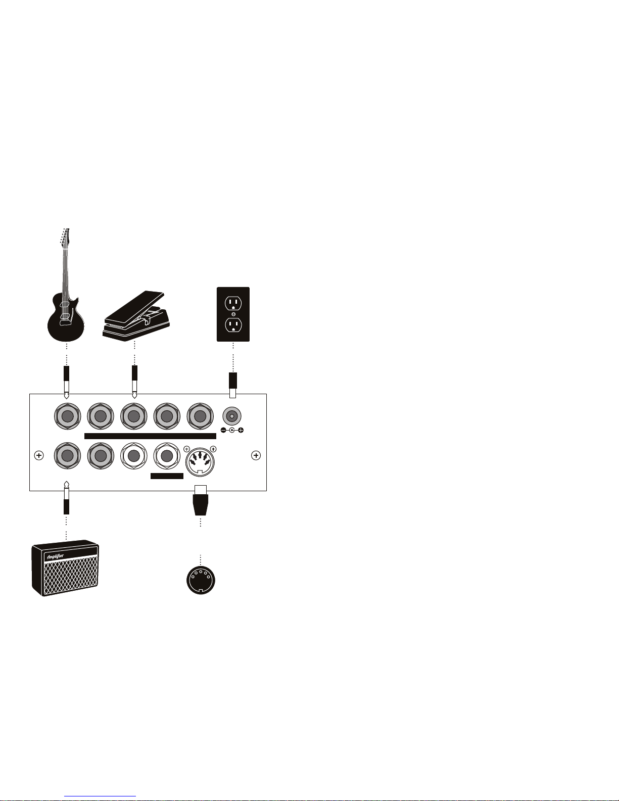
GETTING STARTED
Let’s get sta rted by unpacking and setting up your M F-104M. Here are
some simple instructions on how to plug in and try you r new MF-104M.
AUDIO IN
FEEDBACK TIME LFO RATE MIX
MIX OUT DELAY OUT
FB INSERT
LFO AMT
MIDI IN
+9V
400 mA
Guitar or Instrument Expression Pedal
Power Supply
Amplifier
MIDI Out from
Computer, MIDI
Controller or
Drum Machine
Unpacking
1. Remove your new Mooger fooger f rom the packa ging and allow it a few
moments to get its land le gs after the long journ ey to its new home .
2. Inside the box you’ll find your Analog Delay, AC adapter, warranty card,
and this manual. Save the box in case you ever need to ship your MF-104M
back to Moog M usic.
3. Don’t forget to r egister your Analog Delay. Why? Moog is cons tantly
updating its pr oduct s. The on ly way to know about an update is by
regist ering. The easiest way is by visiti ng: www.moogmus ic.com/register
Connecting
1. Connect an instrument ca ble from your sound source to the AUDIO IN
jack on your MF-104M. You can feed virtually any instr ument or line-level
signal through your MF-104M.
2. If you plan on using MIDI, connect a MID I cable from the out on the M IDI
controller of your choice to the MF-104M’s MIDI IN.
NOTE: The An alog Delay defaults to M IDI Chan nel one. M ake sure you r MIDI contro ller
is transmit ting on MI DI Chann el one.
3. Connect an instrument ca ble from the M IX OUT jack to a line-level in put
on your amp or mixer.
4. Using the supplied power adapter, plug the cord into the +9V jack. Then,
plug the power a dapter itse lf into a wall receptacle.
NOTE: The M F-104M requires a power supply o f +9VDC , CENTE R POSIT IVE, rate d for
at least 40 0mA .
5. Once the power supply is plugged in your Mooge rfooger is ready to
work. You’ll notice that the BYPASS indicator is red. This indicates th e
effect is OFF.
Page 4
6 7
LFO CONTROLS (RIGHT PANEL):
LFO - Six-position rotary switch sel ects the LFO wave shape for de lay
time modul ation. Select from Sine, Triangle, Square, Ram p, Sawtooth, and
Sample and Hold modulation.
LFO RATE - Adjusts the LFO rate from 0.05 Hz to 50 Hz (wider range
available via control voltage s and MIDI).
LFO AMOUNT - Controls the a mount of LFO modulation of the delay time.
NOTE: More d etails on the se controls c an be found o n page 17.
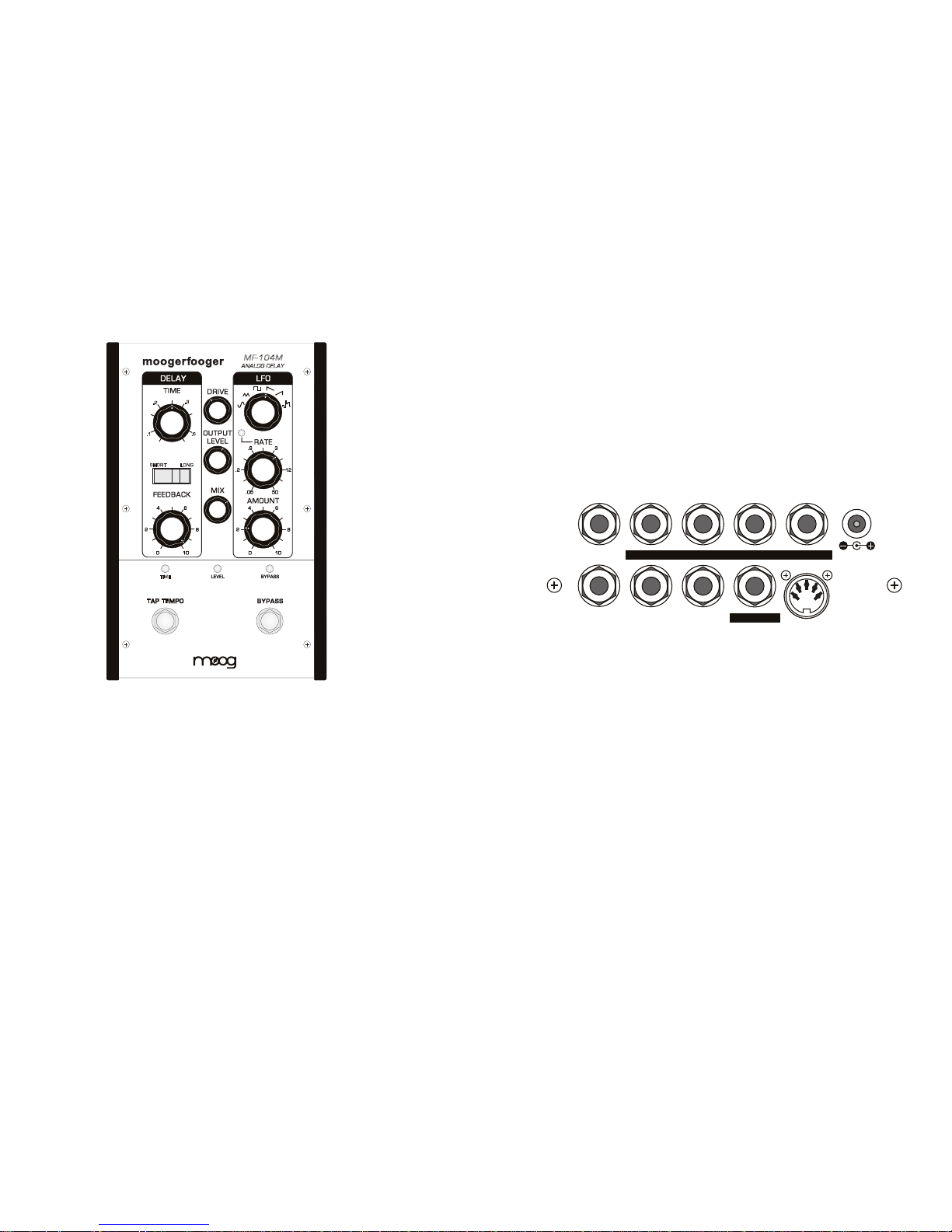
THE MF-104M BACK PANEL
The BACK PANEL ha s all the connection points for sending audio signals in
and out, control voltage in puts, MIDI input, and power supply connector.
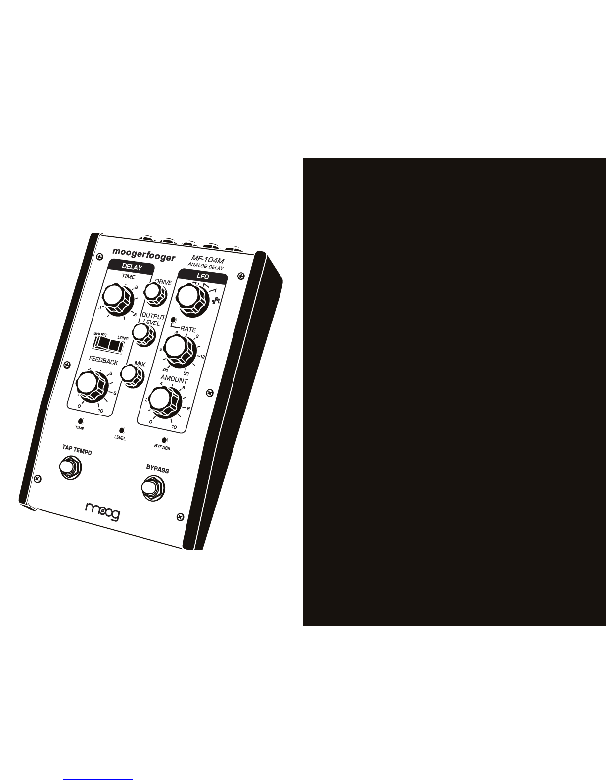
THE MF-104M FRONT PANEL
The FRONT PANEL of the MF-104M Analog Delay conta ins the
performance controls and LED indicators.
MF-104M
ANALOG DELAY
TAP TEMPO
TIME
SHORT LONG
.2
.1
.6
.3
DELAY LINE CONTROLS (LEFT PANEL):
TIME - Adjusts de lay times from 4 0ms to 400 ms in Shor t mode and 80ms
to 800ms in Long mode.
RANGE - Selec ts betwee n Short and Long delay times and bright or dark
filter. The Short setting is brighter while the Long setting is darker.
FEEDBACK - Provide s continuou s control from no feedback to greater
than infinite. NOTE: Feed back sett ings above 8 ca n cause the uni t to self-oscil late.
LEVEL CONTROLS (CENTER PANEL):
DRIVE - Allows 35 dB of adjustment of the input signal for optimum signal
path, level matching and overdriving soun d sources .
OUTPUT - Allows gain and attenuation of output signal for compatibility
with a wide range of input device s.
MIX - Crossfader contro l for blending wet and dry signals to the output.
AUDIO IN
FEEDBACK TIME LFO RATE MIX
MIX OUT DELAY OUT
FB INSERT
LFO AMT
MIDI IN
+9V
400 mA
AUDIO IN - 1/4” TS jack . Accepts any ins trument level to line level
audio signal.
MIX OUT - 1/4” TS jack. Adjustable output level for instrume nt or line
level output.
DELAY OUT - 1/4” TS jack. Supplies wet-only output.
FEEDBACK, TIME , LFO RATE, M IX, LFO AMOUNT - All are 1/4” TRS
jacks that accept Moogerfooge r EP-2 (or equivalent) expression peda ls,
or 0-5VDC control voltages from either two-circuit (TS) or three-circuit
(TRS) 1/4” jacks .
FEEDBACK INSERT - Supplies line-level send and return via a 1/4” TRS jack
for inserting effects into the feedback loop of the Delay line
MIDI IN - Acce pts a 5-pin DIN input for controlling the MF-104 M via MIDI .
+9VDC POWER JACK - Acce pts stand ard 9 volt center positive barrel
power adaptor (power adaptor included). 400mA minimum req uired.
NOTE: More d etails on the se connections can be f ound on pag e 20.
Page 5
8 9
SETTING LEVELS
1. Turn your amp or mo nitor on, then, turn its volume control
down but not of f.
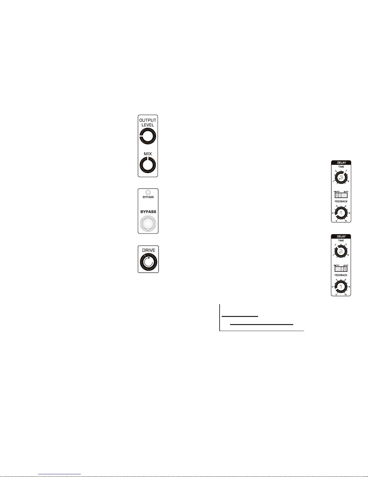
2. On the MF-104M, turn all controls except the MIX and
OUTPUT LEVEL to their far left position . Turn the MIX knob to
12:00 an d the OUTPU T LEVEL to 9: 00 as shown in Figure 1.
3. Press the BYPASS switch so the BYPASS LED turns green
(Figure 2). This means the ef fect is ON. If you pre ss and hold
the BYPASS switch, you’ll see the LED change from red to
orange or gree n. Orange or green indicate that the effect
is on but in diffe rent modes . For now we ’ll foc us on Normal .
•NORMAL MODE – Green LED
•SPI LLOVE R MODE – Orange LED
•OFF – Red LED
4. While playing your instr ument (or signal source) turn the
DRIVE control clockwise as in Figur e 3 until th e LEVEL
LED stays green with occasional orange flashes on pe aks.
Note: Red in dicates cli pping - this is OK if you want to use t he Drive
control to ad d some disto rtion.
5. Tap the BYPASS switch until the BYPASS ind icator is red .
This means the effec t is OFF (bypassed).
6. Play your instrument or source again. Then adjust the
OUTPUT LEV EL control until the overall volume with the
effect o n and with the ef fect bypassed is the same. You may
have to switch the effe ct off and on a few times an d make
small adju stments . Once you find the sweet spot keep those
knobs set to maximize fidelity and signal -to-noise ratio.
Since we know you are eager to start hearing what your Analo g
Delay can do, let’s dig in, learn a little, and hear how the Delay
Line and LFO work together to create some amazing sounds.
If you really n eed some instant gr ati fic ati on s kip to pag e 13
for som e great s etups.
GETTI NG TO KNOW THE D ELAY LINE
As you go through this section, adjust controls as sh own in
the illustrations on the rig ht side of the page to hear how different Delay Line settings affect the audio output.
Adjust the Delay Line settings as shown in Fi gure 4 then
play your instrument. That’s the clas sic “slapback” echo.
Now increase the FEEDBACK control to 5 and play your
instrume nt again. You’ll hear a fast series of decaying e cho es.
As you increa se the FEEDBACK more of the delayed
signal gets sent back through the Bucket Brigade Device
which means a longer se ries of repeats.
Adjust the set tings again as shown in Figure 5 and st art
jamming. There’s that slapback aga in but the delayed sound
is darker (has less treble). Now increase the FEEDBACK to 5.
Play while listening to the echoes and you’ll really notice th e
difference, even if your ea rs are a little co oked from a rece nt
overdose of decibels.
Your Analog Delay was designed with an area of overla p in
the SHORT and LONG delay ranges , with the SHORT range
having a higher frequency respon se. This provid es the abilit y
to fine tune the tonal characteristics of the delayed sound
(see Figu re 6).
FIGURE 1
FIGURE 2
FIGURE 3
DIGGING IN
As you already know by now the MF-1 04M has a Delay Line and a LFO.
To demonstrate how they work we’ll first check out the De lay Line with
the LFO of f. Next, we’ll go over the LFO with the Delay Lin e at the
minimum setting. Then, we’ll put th em together to create some magic.
NOTE: It only s eems like ma gic. In actuality it ’s some ser ious know how o n the part
of Moog’s p roduct des ign team.
FIGURE 4
SHORT LONG
.2
.1
.6
.3
.3
1
FIGURE 5
SHORT LONG
.2
.1
.6
.3
.2
1
FIGURE 6
3.0 KHz
)
(
)
(
40 80
400
800 msec
1.7 KHz
SHORT
LONG
Page 6

10 11
FIGURE 7
7
FIGURE 8
SHORT LONG
.2
.1
.6
.3
1
DELAY TIME = .2
DELAY TIME = .6
FIGURE 9
Take a little time to experiment with variou s settings of th e DELAY TIME ,
SHORT/LONG switch , and FEEDBACK.
Here are som e things you will n otice:
•Changing the SHORT/LONG switch position either halves or doubl es the
DELAY TIME and thus compresses or stretches the delayed signal currently
in the Delay Lin e by a factor of two. This results in the pitch of the de layed
signal being shifted up or down an octave.
•Th e FEEDBACK control creates the series of echoes by mixing a por tion of
the delayed signal back into the Delay Line. With the control set to about
8, the echoes sustain indefinitely. With the FEEDBACK control set above 8,
the echoes build up chaotically into so me amazing electronic textures that
can be both edgy and blurry at the same time.
GETTING TO KNOW THE LFO
This section demons trates how the LFO
modulates th e Delay Line.
Adjust all Delay controls as shown in Figure
10. Press the BYPASS control to bypass the
effect (BYPASS LED = Red).
Play your instrument for a few seconds. Tap
the BYPASS switch again to turn the effect
back on and play some more. Hear the difference? This is due to the fact that with the
effect on the Delay Line is still in the circuit
and is creating a very short (40 millisecond)
echo of the signal.
FIGURE 10
SHORT LONG
.2
.1
.6
.3
0
0
.05
0
Adjust the FEEDBACK as shown in Figure 7, and tap the
BYPASS switch to turn the effect OFF. Then press and h old
the BYPASS switch until the LED turns orange. The M F-104M
is now in SPILLOVER mode.
Play your instrument to build u p some echoes in the De lay
Line. Now ta p the BYPASS switch to turn the effect off while
continuing to play. The signal from your instrum ent will not
be sent through the effe ct but any audio currently in the
circuit will continu e to sound as if the effect were on . Pressing
and holding the BYPASS button for two seconds toggles
your Analog Delay between modes.
•In NORMAL mode, turning the effect OFF shuts off aud io
from the Delay Line. Any new sig nals bypass th e effect.
•In SPILLOVE R mode, turning the effect OFF allows audio
currently in the Delay Line to continue while any new signals
bypass the ef fect.
Play your instrument while turning the TIME control as in
Figure 8. You’ll he ar the pitch of the d elayed signal change
briefly and then return to pitch.
As you chang e the DEL AY TIME the signal b ecomes
stretched or compressed as it goes through the delay circuit,
thereby speeding up or sl owing down the vib rations.
When you cha nge the DELAY TIME you are cha nging the
clock rate of an oscillator that determines how f ast signals
go through the individual circuits in th e Bucket Brigade
Device (see Figure 9).
Adjust your LFO controls as shown in Figure 11. Play your
instrume nt and you’ll h ear a classic chorus ef fect. H ow
does this ha ppen?
We just noted that ch anging the D ELAY TIME changes how
fast signa ls go through BBD in the Delay Line. An d, you’ll
remembe r that changing the TIME will c ause pitch shifting
of audio alre ady in the Delay Line due to time compression
and expansion of the signal.
In the MF-10 4M the LFO is used to modify (or modulate) the
rate at which signals go through the BBD based on the chosen
WAVEFORM, RATE, and AMOUNT. In this exampl e of a
chorus ef fect, the LFO is smoothly modulating the TIME with
a slowly changing sine wave of low amplitude (small pe aks
and troughs). Because the sin e wave is “gentle”, only minor
pitch shifting occurs.
FIGURE 11
.8
4
Page 7

12 13
Adjust the LFO settin gs as shown in Figu re 12. Play your
instrume nt again and you will hear the delayed signal quickly
sliding up and down an oct ave, somewhat like a siren. With
the AMOUNT and R ATE increased, the sin e wave has greater
amplitude and is cycling f aster thus modulating th e delayed
signal more profoundly. If the pitch change is not quite an
octave you might n eed to fine tune these settings slightly.
Increase th e AMOUNT slowly an d, at a setting of around 9,
you will find the p oint where the pitch of the delayed signal
goes up and down by two octaves .
Let’s use anoth er WAVE FO RM and che ck out the differences.
Adjust the settings on your MF-104M as shown in Figure 13.
The delayed sig nal will bou nce up and down one octave
without sliding, or for you m ore classic al types , with no glissando. In theory, a square wave has no slope (See Figur e 14) .
It goes dire ctly from peak to trough to peak without transition. Thus there is no slid ing of the pitch. But in prac tice
there is a brief transition phase which creates odd harmoni cs
and adds a definite edge o r crispness to the tone. If the
octave is not quite right, fine tu ne the AMOUNT slightly.
FIGURE 12
.8
8.0
FIGURE 13
.4
8.0
FIGURE 14
• •• •• •• • • ••• • ••
LFO
TIME
Take a few minutes to experime nt with different WAVE FOR M, R AT E, and
AMOUNT settings.
Since it’s always good to know the waves before you ride, here are some
brief descriptions, listed from lef t to right on the WAVE FO RM control:
•Sine– A periodic wave that smoothly transitions from peak to troug h with
no harmon ics. Creates vibrato and tremolo effects whe n used to modulate
another signal.
•Tria ng le– A periodic wave creates a triangle shape in moving from peak
to trough. Creates similar ef fects to a sine wave when mod ulating another
signal but with a sharper tone due to the generation of odd harmonics.
•Square– A wave that alternates almost instantaneously betwee n two
states. Cre ates octave and other pitch shif ting effects when used to modulate another signal.
•Sawtooth– A wave that very quickly reach es a peak an d then ramps down
more slowly.
•Ramp– A type of sawtooth wave that ramps up slowly to a pea k then
drops down quickly.
•Sample A nd Hold – Also known as a random step, a squ are-ish wave that
randomly changes from up and down state and wave height (amplitude).
PUTTING IT ALL TOGETHER
Having the ability to combin e your instrument or source signal with a
delayed signal that is also mo dulated is on e way in which the M F-104M
stands apart. The following four setups conta in some familiar uses of th e
Delay Line with the LFO providing a n interesting t wist. And s peaking of
twist, th ese setups are just begging for some serious k nob turning,
expression pedal wiggling, and other creative high jinks.
The front panel controls a re referred to as performa nce controls for a
reason: They are meant to be played. Your MF-104M Analog Delay is a
musical instrument in itself.
1. STRETCHING TAPE
Classic tape style de lay with a stretching
effect courtesy of triangle wave modulation.
Try plugging a Mo og EP-2 expression pedal
into the Rate CV jack and use it to spe ed up
or slow down that stretching effect.
TIME
SHORT LONG
.2
.1
.6
.3
Page 8

14 15
2. VIBROLAY
A spatial vintage style delay with triangle
wave vibrato added to the trails. Try quick
notes or chord s combined with held notes .
Use the Rate and A mount kno bs to add
different flavor and feel.
4. SQUARE ROOT
Prepare for o ctave action with this
awesome squa re wave mod. Each note
will rhythmically jump up and down a full
octave for percussive bliss . Assign Tap
Tempo to the LFO Rate and stom p away.
Note: If the pitc h change is no t quite an octave
you might nee d to fine tune th ese settings slightly.
3. STAIR STEPPER
This Ramp modulated preset will have notes
working their way through the roof. Play a
note and let the d elay do the rest.
Use the Short/Long switch for even more
musical mangling.
TIME
SHORT LONG
.2
.1
.6
.3
TIME
SHORT LONG
.2
.1
.6
.3
TIME
SHORT LONG
.2
.1
.6
.3
A NOTE ABOUT TAP TEMPO
The TAP TEMPO switch on your Analog Delay can b e used to control either
the DEL AY TIME or the LFO RATE. To set a tempo, simply tap th e switch
at the desired tempo, in quarter notes . After the third tap the MF-104M will
start calculating th e tempo and keep the average tem po as you contin ue
to tap. To start over, wait five secon ds and then press the TEMP O switch
three times to set a new tempo. To revert to using th e front panel control,
turn either the TIME knob or LFO RATE knob (depending on which tem po
you are setting).
•Pressing a nd holding the TAP TEMPO control for at least one second
toggles the Tap Tempo func tion between the LFO RATE and DELAY TIME.
•The LED indicator for the function being controlled by Tap Tempo will
flash green and flash in sync with the chosen tempo.
SOME HE LPFUL TI PS
•You can use the DRIVE control to create some warm analog distor tion of
the input if you so choose.
•By using the TAP TEMPO control to ta p very slowly or very quickly, you
can set “illegal” tem pos that go outside of the designed ranges of the LFO
and BBD. D oing so creates aliasing ar tifacts that can sou nd like ring modulation. It isn’t prett y but it can sound very cool. Please use judiciously.
Page 9

16 17
ABOUT ANALOG DELAYS
A delay circuit produces a replica of an audio signal a short time af ter the
original signal is received. If you listen to the original (direct) signal and the
delayed signal together, the del ayed signal will sound like an echo of the
direct. To make a whol e series of echoes that die out gradua lly, you feed
the delayed output signal back to the input . You can determine how far
apart the echoes are by adjusting the delay time of the d elay circuit, and
you can adjust how fast the echoes die out by adjusting the amount of
feedback from the delay. In addition, you can determine how loud echoes
are by adjusting the mix betwe en the direc t signal and the delayed signal.
During the e arly 1970s, large-scale semiconductor analog delay circuits
came into being. These are called B ucket Brigade Delay (BBD) chips,
because they function by passing the audio waveform down a chain of
several thousand circuit cells, which is analagous to water being passed by
a bucket brigade to put out a fire. Each cell in the chip intro duces a tiny
delay. The total time delay depends on the number of cells a nd on how
fast the waveform is “clocked”, or moved from one cell to the next.
In the MF-10 4M, the LFO creates a control voltage that is used to modulate
the time fun ction of the delay. The BBDs in the Delay Line contain 8192
“buckets”. With the time unmo dulated the signal spends the same amount
of time in each b ucket based o n the selec ted delay time. With the time
modulated by the LFO, the time is no longer constant (or static) and audio
signals already in the bu ckets get time compressed or stretched . A good
analogy for picturing this is a clock with a sweep han d to show the seconds.
Imagine th at you could hold the sweep ha nd and either slow it down or
speed it up. Yet, when you let it go the swe ep hand instantly went to the
correct p osition on the clock face. In a sense, this is how the LFO
modulates th e Delay Line.
In an analog delay the inp ut can be set to saturate gradually, limiting the
maximum signal level and introducing som e low level distortion. This actually
enhances the sound quality over what you would have if the MF-104M
produced n o distortion whatsoever.
THE MF-104M FRONT PANEL
This section provides more in-depth descriptions of the controls a nd
indicators on the MF-10 4M front panel.
MF-104M
ANALOG DELAY
TAP TEMPO
TIME
SHORT LONG
.2
.1
.6
.3
DRIVE CONTROL - Sets the input sensitivity of the Analog Delay. This
control is only a ctive when the effect is ON or in SPILLOVER mode. The
available gain runs approximately 35d B. The Analog Delay is d esigned to
work with instrument to line -level signals.
LEVEL LE D - Works in conju nction with th e DRIVE control. Red ind icates
clipping . Orange flashes indicate the star t of overload . Green indicates the
presence of signal at or below the nominal level.
NOTE: For mos t instrume nts, the b est appro ach is to set the D RIVE level so the LEVEL
LED stays consi stently gre en with only p eaks in the or ange. It is okay to drive the Ana-
log Delay into clip ping/disto rtion if that sound is de sire d. W he n us in g a n in st ru ment
with a wide d ynamic r ange, you may want to inser t a compressor or limiter prior to
the input of th e Analog De lay for the best signal-to -noise rati o without clip ping.
Page 10

18 19
LFO RATE - Sets the frequency of modulatio n of the Delay Lin e by the
LFO. The R ATE can be varied fro m .05 Hz to about 50 Hz. The LFO RATE
LED indicates both the R ATE and WAV EF OR M of the current LFO settings.
The LED is red wh en the R AT E is set from the front panel, green when the
rate is set by the TAP TEMPO switch, and orange when the LFO is synced
to MIDI clock. When synced to MIDI clock, the R ATE control is quantized to
select only rhythmic subdivisions of the MIDI clock tempo .
LFO AMOUNT - Sets the overall amount of modulation of th e Delay Line
by the LFO.
Note: As the L FO Amount in creases , the fun ctional range of the DE LAY TIME control
is decrea sed, so that th e maximum a nd minimum delay times ar e not exceed ed
.
BYPASS - Used to turn the ef fect ON and O FF. When the ef fect is on the
Bypass LED is green. When the effect is in SPILLOVER mode the BYPASS
LED is orang e. When the effect is off the BYPASS LED is red.
TAP TEMPO - Dedicated switch used for setting the DELAY TIME or the
LFO RATE to a musical tempo.
To initiate Tap Tempo control of the DE LAY TIME, press the TAP TEMPO
switch three times with the tempo you want (quarter notes). On the third
press, the TIME LED will change to Green, and the DELAY TIME will change
rates to match the timing of the switch presses.
If you continue to press the TAP TEMPO switch, the TIME will be set by a
running average of the time between switch presses. To start over, wait
five seconds and then press the TAP TEMPO switch three times to set a
new tempo.
To revert the unit to front panel control, simply turn th e TIME control. The
TIME LED will turn red, a nd the DEL AY TIME will set by the pa nel control.
To initiate Tap Tempo control of the LFO, p ress and hold the TAP TEMPO
switch for at least one secon d. The LFO LED will flash green to show that
the tap tempo is now routed to the LFO a nd not the DE LAY TIME. To
change ba ck, press and hold the TAP TEM PO switch again until the TIM E
indicator fl ashes green.
When Tap Tempo is routed to the LFO pressing the switch three times or
more will set the LFO rate to match the tap time. Turning the R AT E kno b
reverts the unit back to front panel control.
Note: When e ither desti nation (time o r LFO) is synch ronized to MI DI Clock m essage s,
Tap Tempo is disable d for that destination onl y
.
OUTPUT LE VEL - Sets the stren gth of the Analog Delay output at the
MIX OUT and DELAY OUT jacks. This control is only ac tive when the ef fect
is on or in Spillover mode. Th e OUTPUT LEVEL contro l is designe d so that
an overall boost, attenuation or zero gain s tate can be achieved with any
DRIVE setting.
MIX - Sets the ratio of dry (signal as input) to wet (effected) signal. This
control is only a ctive when the effect is on. Set fully counterclockwise it
allows only th e dry signal to pass to the MIX output. The full clockwise
position allows only the wet sign al to pass to the MIX output. Any position
between the two will blend wet and dry signal to the output. The D E LAY
OUT signal is not af fected by the MIX control.
Note: If you’re a pplying a su stained ste ady pitch to th e MF-104 M and the MIX cont rol
is set near 12 :00, you m ay find that the di rect and de layed signals a lternately r einforce
and cance l each othe r in rapid suc cession a s the DELAY TIM E is varied . This is a normal result of mixing a steady pitch with a delayed r eplica of itself. It i s the anal ogdela y equ ival ent of “st anding waves ” in a reverbe rant room .
DELAY TIME - Sets the length of delay from the BBD Delay Line based
on the SHORT/LONG (Delay Range) switch setting. I n SHORT mode, with
AMOUNT set to 0, the de lay time changes from approximately 40ms to
400ms n ominal. I n LONG mode the available span is from ap proximately
80ms to 80 0ms nominal. The D ELAY TIME is modulated via th e LFO to
create various effect s.
Since the delay’s internal anti-alias filter must change for the delay time,
the SHORT setting will yield a higher freq uency response for the same delay
time as LONG. Switching from SHORT to LONG will reduce the sound in
the “fee dback loo p” one octave, while switching the other direction will
double the pitch and time of th e loop soun d.
FEEDBACK - Sets the amount of D elay Line output fed back into the input
of the Bucket Brigade Device. The feed back is variable from of f, slapback
or single repeats, to continuous repeats (at about the 3:00 setting). When
turned past 3:00, the FEEDBACK provides for self-oscillation and swelling
delay sounds.
WARNING: The Analog Delay Fe edback c ontrol is ab le to drive the Delay Line into
self-oscil lation. This me ans the Analog D elay is capable of pr oducin g sou nds w itho ut
any audio sig nal prese nt. Tones produc ed by self-osc illating fee dback may b e much
stronger t han normal s ignal levels . Plea se watch yo ur spea kers and e ars. Os cillation
typical ly begins at t he 3:00 pos ition.
LFO WAVEFORM - Selects the LFO waveform for modulation of the Delay
Time. The re are six waveforms available: Sine, Triangle, Square, Sawtooth,
Ramp and Sample and H old (Rand om Stepped) waveforms.
Note: No mod ulation will b e heard with th e LFO AMOU NT set to zero .
Page 11

20 21
FEEDBACK - 1⁄4” TRS jack that can be used with a Moog EP-2 expression
pedal, or a 0V to +5V control voltage on a standard TS cable. A setting of
0 volts or ground allows for no fe edback while a 5V settin g gives infinite
feedback. To change the fee dback amount from zero to infinite via control
voltage or expression ped al, set the FEEDBACK control to 12:00 position.
TIME - 1⁄4” TRS jack th at can be use d with a Moog EP-2 expression pedal,
or a 0V to +5V control volta ge on a standard TS cable. To change the DELAY TIME for a selected range from longe st to shortest via control voltage
or expression pedal, set the DELAY TIME control to 12:0 0 position.
LFO RATE - 1⁄4” TRS jack that can be used with a Moog EP-2 expression
pedal, or a 0V to +5V control voltage on a standard TS cable.
To use an expression pedal to modif y the LFO Rate (0.05 Hz to 50 Hz) set
the LFO R ATE to 12:00 position. Rot ate the LFO R ATE knob counterclockwise. With a 0V control voltage applied to the LFO Rate CV input, the L FO
Rate can be reduced to half of the minimum pa nel rate. (.025 Hz) Now
rotate the LFO R ATE control f ully Clock wise. With a +5V control voltage
applied to the LFO Rate CV input, the LFO Rate can be increased to double
the maximum panel rate. ( 100 Hz)
LFO AMOUNT - 1⁄4” TRS jack that can be used with a Moog EP-2 expression pedal, or a 0V to +5V control volt age on a standard TS cab le. To
modify the LFO AMOU NT from minimum to maximum via control voltage
or expression pedal, set the LFO AMOU NT control to 12: 00 position.
MIX - 1⁄4” TRS jack that can be used with a Moog EP-2 expres sion pedal,
or a 0V to +5V control volta ge on a standard TS cable. To change the Mix
from dry to wet via control voltage o r expression p edal set the M IX control
to 12:00 position.
MIDI IN - Standard 5-pin DIN for receiving MIDI messages from an other
MIDI device such as a MID I controller o r a sequencer. Refer to the MIDI section of this man ual for use of th e Analog Delay with other MIDI devices .
POWER - For connec ting to the supp lied power adapter. Note: Use onl y the
proper p ower supply t o avoid damage to the device. M ake sure your p ower suppl y has
the correc t Input voltage specifi cations for your countr y:
• 120VAC/60 Hz for the US and Canada
• 230VAC/ 50 Hz for Europe an d South Ame rica
The output of the adapter is +9VDC and the adapter should be capable of
supplying a minimum of 400mA . The +9VDC is a pplied to the tip (center)
of a barrel connector plug w/ 5.5mm outer diameter and 2.1m m inner
diameter. The barrel (outside) of the plug is th e ground (-).
TIME INDICATOR LED - Flashes red to indic ate the delay time. It will flash
green to indicate that it is synced to Tap Tempo and ora nge when it is controlled by MID I.
THE MF-104M BACK PANEL
This section provides greater detail of the connection points on the MF104M back panel.
AUDIO IN
FEEDBACK TIME LFO RATE MIX
MIX OUT DELAY OUT
FB INSERT
LFO AMT
MIDI IN
+9V
400 mA
AUDIO IN - This 1⁄4” jack provides high impedance, unbalanced a udio input. The Analog Delay accepts signals ranging from instrument to line level.
MIX OUT - This 1⁄4” jack provides a n unbalanced audio o utput. When the
effect is on, this output carrie s the dry an d wet signal blend set on the
front pane l MIX control. The level is determined by the DRIVE and OUTPUT
level controls. When the ef fect is of f, the input signal passes only through
a high-quality buf fer on its way to the output.
DELAY OUT - This 1⁄4” jack provides a n unbalanced audio o utput. This is a
wet-only output, in phase with the MIX output. Th e level is affected by the
OUTPUT LEVEL knob but not th e MIX knob. T his output can be used as a
second output in STEREO app lications o r as a feed for phasing ef fects.
FEEDBACK (FB) INSE RT - This 1⁄4” TRS jack is designed to be used with a
standard insert cable to process the BBD feedback signal path separately
from the dry signal path . This is an unbalanced, line level output and input.
The BBD output signal appears at the tip of the jack, and the retu rn to the
device is applied to the ring of the jack.
Because these are line level signals , some means of attenuation or amplification may be required if using devices designed for lower signal levels,
such as typical guita r stomp boxes.
Note: Unli ke the classi c MF-104 SD and M F-104Z, t he FEEDBACK insert is placed
before the fi rst delay in t he feedb ack.
Page 12

22 23
CIRCUIT CONFIGURATION
The figure below is a simplified block diagra m of the MF-104M Analog Delay.
MIDI CONTROL OF THE MF-104M
The following section explains the MI DI implementation of th e MF-104M.
For information about what MIDI is and how it works, you can go to the
following web page for tutorials: www.midi.org/aboutmidi/tutorials.php
MIDI CHANNEL
The default MIDI Channel for th e MF-104M is Channel one. To change this ,
press and hold both the TAP TEMPO and BYPASS switches. While holding
both, send a MIDI Cha nnel mod e message to the Analog Delay on the
desired MIDI chann el. The TIME LED will flash yellow indicating that the
message has been received. The M F-104M will n ow only receive MIDI messages on that channel. The current MIDI Input chann el is stored in memory
on power down.
Note: MID I Clock an d System Exclusive messages are N OT Channel Mo de messa ges,
and are rec eived by the An alog Delay re gardles s of the curre nt MIDI I nput Chan nel.
MIDI CONTROL CHANG E (CC) MESSAGES
The settings of the Analo g Delay can be controlled by MI DI Control Change
(CC) messages . In addition to the front panel controls , there are a nu mber
of advanced features that c an be enabled and edited with CC messa ges.
A MIDI CC message has b oth a CC number from 0-127 and a value from
0-127. The CC values that affect panel controls replace th e physical set ting
of the front panel controls . When the co rrespond ing front panel control
is changed after receiving a MIDI CC message , the value will return to
that panel control. MSB/LSB refers to 14-bit MIDI which uses a pair of CC
messages to obtain high er resolution control. Use the MSB CC nu mbers to
control these p arameters at 7-bit resolution.
Note: Moving a p anel control while
receivin g MIDI CC m essage s for that sam e control will r esult in con flicting val ues.
THE FOLLOWING CC MESSAGES CORRESPOND TO PANEL CONTROLS:
THE FOLLOWIN G CC MESSAGE S DO NOT CORR ESPON D TO FRONT
PANEL CONTRO LS, BU T EXTEND THE ANALOG DELAY’S CAPABILITIES.
CC NUMBER
7(MSB), 39(L SB)
12(MSB), 44 (LS B)
13(MSB), 45 (LSB)
14(MSB), 46(LSB)
15(M SB), 47(L SB)
16(M SB), 4 8(L SB)
102
86
80
PARAMETER
VAL UE S
Output Level
Time
Feedback
Mix
LFO Rate
LFO Amount
LFO Waveform
Range(Fast/Slow)
Bypass on/off
0-16 383 (MSB , LS B)
0-16383 (MSB, LSB)
0-16383 (MSB, LSB)
0-16383 (MSB, LSB)
0-16383 (MSB, LSB)
0-16383 (MSB, LSB)
0-15=Sine, 16 -3 1=Tri a n gle
32-47=Square, 48-63=Saw
64-79=Ramp, 80-95=S&H
96-127=Smooth S&H
0=Slow, 64=Fast
(Moves 1 O ctave)
0-63=Bypassed,
64-1 27=Act ive
�
CC NUMBER
PARAMETER
VAL UE S
5(MSB), 37(LSB)
83
85
87
89
105
107
Time Slew Rate
Pitch Bend Amount
Filter Bright/Dark
Delay Time
Multiplier
Delay Time MIDI
Sync Enable
LFO Phase Reset
LFO Clock Divisions
0-16383 (MSB, LS B)
0 = Off, 16 = 2 Semi
32 = 3 Semi, 48 = 4 Semi
64 = 5 Semi, 80 = 7 Semi
96 = 12 Semi, 112 = 24 Semi
0-63 = Bright
64-127 = Dark (Only adjusts
filter, does not affect range)
0-31=Norm, 32-63=x2
64-95=x4, 96-127=x8
0-63 = Disabled
64-127 = Enabled
Any Value=Reset
LFO Phase to 0.
(See Separate table)
Page 13

24 25
time to a musical fraction or multiple of the base time (M IDI note 60/C4
does not change the delay time).
Ex: C3 doubles the delay time (and pitches down any audio in the delay line
by an octave) and C5 halves the delay time (pitching any audio in the delay
line up by an octave).
DELAY TIME M ULTIPLIER
The Delay Tim e Multiplier multiplies the delay time by 2, 4 or 8 vastly extending delay time. This fe ature is for obtaining unu sual/lo -fi echo effects.
When the de lay time is incre ased past th e default maximum delay time
available on the front panel, the BB D Clock sign al will be audible.
MIDI CLOC K SYNC
Both Delay Tim e and LFO Rate ca n be synchronized to MIDI System Realtime Clock messages . These messages are 24 ppq messag es that can be
sent via MIDI computer sequence rs or from drum machines. To enable the
sending of th ese messa ges, consult the user m anual for your MIDI device.
When the Analog Delay receives MIDI Clock mess ages, the correspon ding
LED turns Orange to indic ate that it is synchronized to the MI DI Clock tem po. When the LFO is synchronized to a MIDI Clock tempo, the LFO can be
set to divisions of this tempo. This is either from the front pa nel LFO Rate
control, or from MI DI CC# 107. Delay Time MIDI sync is enabled via CC# 89.
Note: Delay T ime MID I Clock Sync overrides M IDI Note Mode. If the D elay Time is synchronized to M IDI Clo ck, then ti me change s due to MID I Note Mode are ignored .
MIDI SYSE X MESSAGE S
Used for updating or finding out the unit’s firmware version. For m ore
information about this , refer to user notes with any firmware updates
posted in the Analog Del ay section of the Moog Music website.
CONTROL VOLTAGE INPUTS
•All CV input jacks are 1/4” tip-ring-sleeve pho ne jacks. The sleeve is
grounded and the ring terminals are supplied with +5 volts which is currentlimited. The tip terminals receive the variable voltages from the pedals.
•An expression pe dal for use with the MF-104M should contain a 50K Ohm
or lower linear taper potentiometer.
•Applying a var ying voltage to a pedal control input jack h as the same
effect a s turning the correspon ding knob. With the pane l controls set to
mid-position, a voltag e control of abo ut 5 volts is equ al to turning the
correspon ding knob through its entire range.
•Note that with the Analog Delay, you may use standa rd TS cables for
control voltages at the same time as Expre ssion pedals.
LFO CLOCK DIVISIONS (CC#71)
CC#71 VALUE CLOCK DIVISION CC#71 VALUE CLOCK DIVISION
0-5 4 Whole 64-69 1/2 T
6-11 3 Whole 70-75 1/4
12-17 2 Whole 76-81 1/8 Dot
18-23 WH + 1/2 Dot 82-87 1/4 T
24-29 WH + 1/2 88-93 1/8
30-34 WH + 1/4 94-98 1/16 Dot
35-40 WH 99-104 1/8 T
41-46 1/2 Dot 105-110 1/16
47-52 WH T 111-116 1/16 T
53-58 1/2 117-122 1/32
59-63 1/4 Dot 123-127 1/32 T
MIDI NOTE M ODES
The MF-104M delay time can be controlled from MIDI Note On messages.
When this mode is enabled the unit receives a MIDI “ Note On” message.
The “Note O N” number determin es the Delay tim e. The unit responds to
MIDI note numbers 0 to 90. The MID I Note On Velocity value is igno red.
In Absolute mode each MIDI note corresponds to a delay time value. In
Relative mode, the delay base time is set by the Time knob, external CV,
or Time MIDI CC. MI DI notes high er or lower than C4 will change the delay
CC NUMBER
PARAMETER
VAL UE S
108
109
110
113
114
115
117
119
Enable LFO MIDI
Sync
Enable LFO Note
Reset
Enable MIDI Note
Spillover
MIDI Note Mode
MIDI Tap Tempo A
MIDI Tap Tempo B
Time/MIDI
LED Select
Enable Mod Wheel
to LFO Amount
0-63 = Disabled
64-127 = Enabled
0-63 = Disabled
64-127 = Enabled
0-63 = Disabled
64-127 = Enabled
0-41 = Off
42-83 = Absolute
84-127 = Relative
Any CC Value = a tap
(value > 63) = a tap
0-63 = Time LED
64-127 = MIDI LED
0-63 = Disabled
64-127 = Enabled
Page 14

26
WARRANTY AND SERVICE INFO
LIMITED WARRANTY
Moog Music warrants that its produc ts will be free f rom defect s in materials
and workma nship, and s hall conform to specifications current at the time
of shipm ent, for a period of one year from date of purchase. Du ring the oneyear period, any defective products will be repaired or replaced, at Moog
Music’s option, on a return-to-factory basis. This Warra nty covers defec ts
that Moog Music determines are no fault of the use r.
RETUR NING YOUR M F-104M FOR REPL ACEMENT/REPAIR
You must obtain prior approval and an RMA num ber from Moo g Music before
returning any product to us. Wrap your M F-104M ca refully and pack it with
the power adapter in its origi nal carton. The wa rranty will not b e honored
if the product is not properly packed. Send it to Moog M usic with transportation and insurance charges paid. A reasonable cost for service , materials
and return freight will be charged to replace materials defective through
the fault of the user, or for which the one year warranty period has expired.
Transportatio n and insurance charges from Moog Music to your United
States address, of produ cts repaired or repla ced under warranty will be
paid by Moog M usic.
Page 15

Note: Specifications subject to change without notice.
Moog®, and Moogerfooger® are registered trademarks of Moog Music Inc.
©2012 Moog Music Inc
MOOG MUSIC INC. 160 Broadway St. Asheville, NC 28801
P: (828) 251-0090 E: info@moogmusic.com W: www.moogmusic.com
 Loading...