

Page 1
MSDServoDrive
User Manual
PROFIBUS / PROFINET
moog
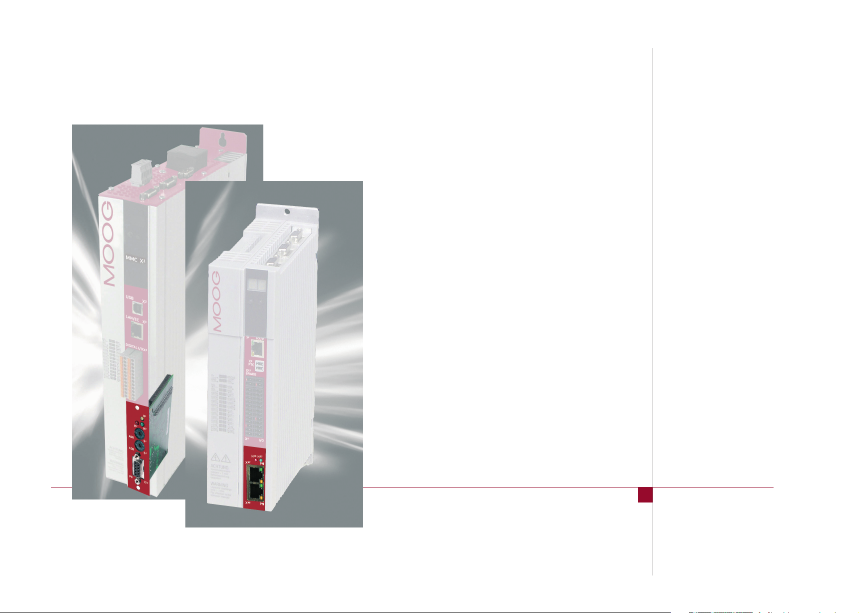
Single-Axis ServoDrive - Compact
Single-Axis ServoDrive - Standard
Multi-Axis ServoDrive - System
Page 2

moog
This document details the functionality of the following devices:
ID no.: CA65645-001 Date: 01/2015
Single-Axis ServoDrive - Compact
Single-Axis ServoDrive - Standard
Multi-Axis ServoDrive - System
MSD Servo Drive User Manual PROFIBUS/PROFINET
2
PROFIBUS/PROFINET User Manual for MSDServoDrive
ID no.: CA65645-001, Rev. 3.0
Date: 01/2015
Subject to technical change without notice.
The German version is the original of this Operation Manual.
Subject to technical change without notice.
The contents of our documentation have been compiled with greatest care and in
compliance with our present status of information.
Nevertheless we would like to point out that this document cannot always be updated
parallel to the technical further development of our products.
Information and specifications may be changed at any time. For information on the
latest version please refer to drives-support@moog.com.
Page 3

How to use this document
Dear us er,
This manual is intended for use by project engineers, commissioning engineers and
programmers of drives and automation solutions involving the PROFIBUS/PROFINET
fieldbus. It is assumed that you are already familiar with at least one of these fieldbuses
on the basis of appropriate training and reading of the relevant literature. We assume
that your drive has already been commissioned – if not, please first refer to the user
manual.
11 General introduction
Appendix: Glossary, Index
22 Commissioning
33 Cyclic data transfer
44 Acyclic data transfer
55 Operation modes
66 Homing
77 Examples of commissioning
88 PROFIBUS/PROFINET parameters
moog
ID no.: CA65645-001 Date: 01/2015
MSD Servo Drive User Manual PROFIBUS/PROFINET
3
Page 4
moog
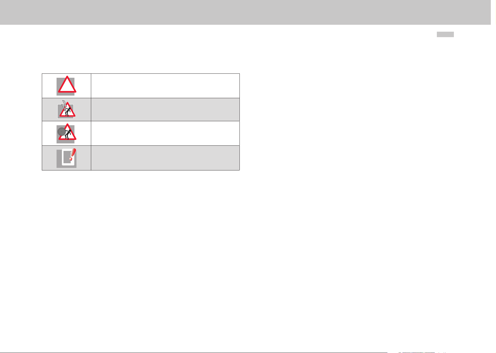
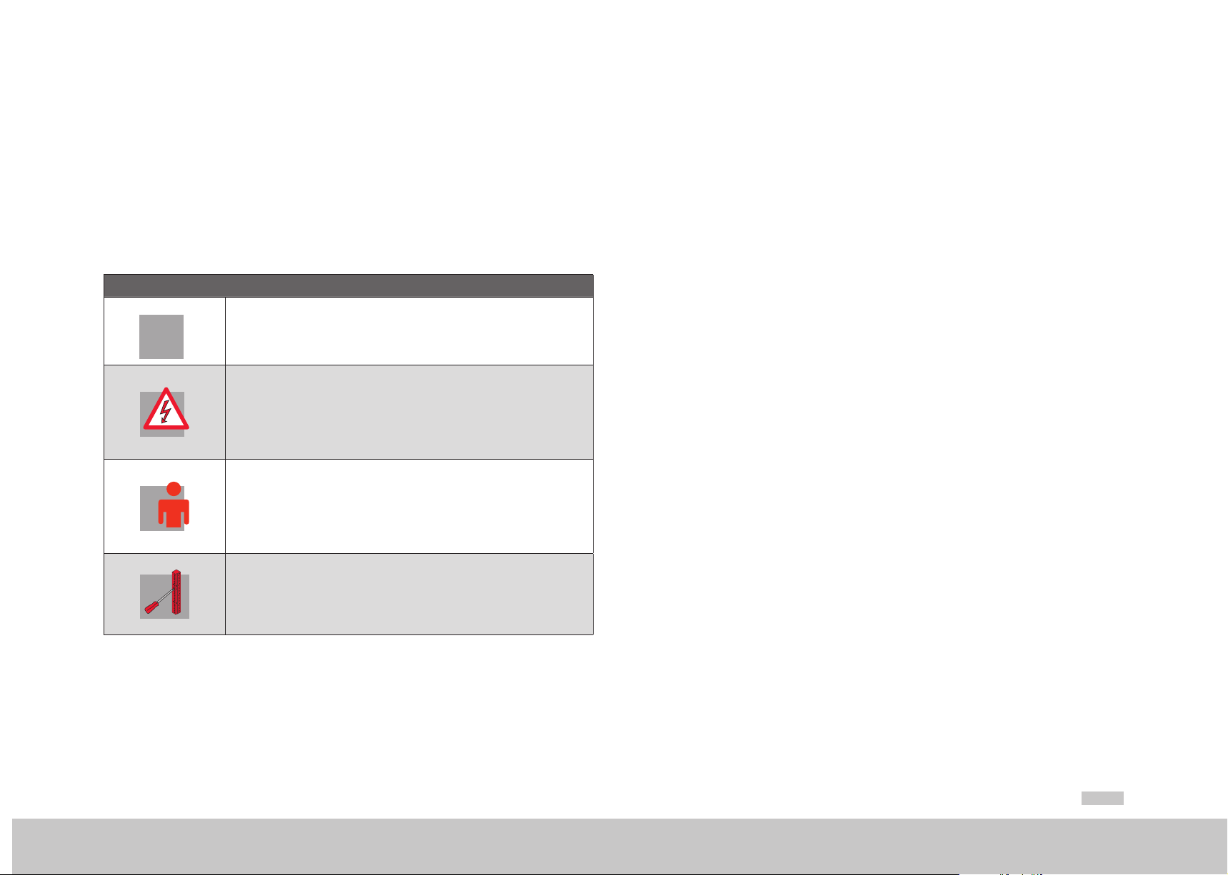
Pictograms
!
ID no.: CA65645-001 Date: 01/2015
Attention! Misoperation may result in damage to the drive or malfunctions.
Danger from electrical tension! Improper behaviour may endanger human life.
Danger from rotating parts! Drive may start up automatically.
Note: Useful information
MSD Servo Drive User Manual PROFIBUS/PROFINET
4
Page 5

Table of contents
1 General .................................................................................... 7
1.1 Measures for your safety .....................................................................................7
1.2 Introduction ........................................................................................................7
1.3 System requirements ........................................................................................... 7
1.4 Further documentation .......................................................................................7
1.5 Helpline/Support & Service ..................................................................................8
2 Commissioning ......................................................................... 9
2.1 PROFIBUS ...........................................................................................................9
2.1.1 Connections and user controls .............................................................9
2.1.2 Pin assignment of the D-Sub socket .....................................................9
2.1.3 Specification of the PROFIBUS cable ....................................................10
2.1.4 Bus termination ...................................................................................10
2.1.5 PROFIBUS address setting ....................................................................11
2.1.6 PROFIBUS option card displays .............................................................11
2.1.7 GSD file (PROFIBUS) .............................................................................12
2.2 PROFINET ............................................................................................................13
2.2.1 Connections ........................................................................................13
2.2.2 Pin assignment of the RJ45 socket .......................................................13
2.2.3 Specification of the PROFINET cable ....................................................14
2.2.4 Meanings of LEDs ................................................................................14
2.2.5 PROFINET option card displays .............................................................15
2.2.6 GSDML file (PROFINET) ........................................................................15
3 Cyclic data transfer ................................................................. 17
3.1 Parameter process data objects (PPOs) ................................................................17
3.1.1 Standard "PROFIdrive" telegrams.........................................................17
3.1.2 User-specific PPOs ................................................................................19
3.1.3 Parameter channel PKW ......................................................................23
3.2 Monitoring ..........................................................................................................24
3. 2 .1 Watchdog ............................................................................................24
3.2.2 Sign of Life...........................................................................................24
4 Acyclic data transfer ............................................................... 27
4.1 PROFIBUS parameter access ................................................................................ 27
4.2 PROFINET parameter access ................................................................................29
4.3 "Base Mode Parameter Access" data format .......................................................29
4.4 Examples of request and response telegrams ......................................................32
5 Profidrive operation modes ..................................................... 35
5.1 Profinet operation modes ....................................................................................35
5.1.1 Speed control circuit and associated control parameters ......................36
5.2 Drive state machine .............................................................................................37
5.3 Jog mode ............................................................................................................38
5. 3 .1 Jog mode manufacturer-specific ..........................................................38
5.3.2 Jog mode conforming to profile ...........................................................38
5.3.3 Jog mode reference parameters ..........................................................39
5.4 Speed control (application class 1) .......................................................................39
5. 4 .1 Master control word ............................................................................40
5.4.2 Drive status word .................................................................................41
5.5 Position control (application class 3) ....................................................................42
5.5.1 Position control circuit and associated control parameters ...................44
moog
ID no.: CA65645-001 Date: 01/2015
MSD Servo Drive User Manual PROFIBUS/PROFINET
5
Page 6

moog
ID no.: CA65645-001 Date: 01/2015
6 Homing .................................................................................. 49
6.1 Drive-controlled homing .....................................................................................49
6.2 Homing velocity ..................................................................................................49
6.3 Homing acceleration ...........................................................................................49
6.4 Zero point offset .................................................................................................49
6.5 Homing method ..................................................................................................49
6.6 Reference cam, limit switch .................................................................................51
7 Examples of commissioning with manufacturer-specific
telegrams ............................................................................... 53
7.1 Position control with PPO 5 .................................................................................53
7.2 Controlled homing ..............................................................................................54
7.3 Conversion of reference and actual values via the factor group parameters .......54
7.4 Examples for setting the user factor group ..........................................................56
7.5 Speed control with PPO 2 ...................................................................................56
7.5.1 Speed input .........................................................................................57
7.6 Mappable parameters .........................................................................................58
MSD Servo Drive User Manual PROFIBUS/PROFINET
6
8 PROFIBUS/PROFINET parameters ............................................. 59
9 Appendix ................................................................................ 61
9.1 Glossary ..............................................................................................................61
9.2 Technical data .....................................................................................................61
Page 7
1 General
1.
1.1 Measures for your safety
1.2 Introduction
PROFIBUS based on standards and its modular interfaces. Thanks to its use of a
single standardised, non-application-dependent communication protocol, PROFIBUS
provides solutions for the process industry as well as in a wide range of motion control
applications.
Servo drives of the MSDServoDrive family are quick and easy to handle. For your
own safety and for the safe functioning of your device, please be sure to observe the
following points:
Read the Operation Manual first!
x Follow the safety instructions!
Electric drives are dangerous:
x Electrical voltages > 230 V/460 V:
Dangerously high voltages may still be present 10minutes after the power is
cut. So check that the power has been cut!
x Rotating parts
x Hot surfaces
Your qualification:
x In order to prevent personal injury and damage to property, only
personnel with electrical engineering qualifications may work on the device.
x Knowledge of the national accident prevention regulations (such as VBG4
inGermany)
x Knowledge of layout and interconnection of fieldbuses
U
U
V
V
N
N
L+
L+
RB
RB
L-
L-
L3
L3
L2
L2
L1
L1
During installation observe the following instructions:
x Always comply with the connection conditions and technical specifications.
x Electrical installation standards,such as cable cross-section, shielding, etc.
x Do not touch electronic components and contacts (electrostatic discharge
may destroy components).
PROFINET permits enhanced system-wide connectivity, adding to tried and
proven PROFIBUS technology for applications specifying fast data communication
in combination with industrial IT functionality. Thanks to its Ethernet-based
communication, PROFINET meets a wide range of requirements, from data-intensive
parameter assignments to synchronised data transfer. Communication for all applications
is routed through just one cable. Whether for a simple control task or for highly
dynamic motion control of drive axes. TCP/IP-based communication in the PROFINET
network enabling extensive system diagnostics in a control station or over the Internet is
implemented in parallel with real-time communication.
1.3 System requirements
− PROFIBUS/PROFINET configuration program installed.
− PROFIBUS/PROFINET device description file for corresponding field device
installed.
1.4 Further documentation
y Instructions for commissioning the drive device
y PROFIBUS user organisation "PROFIdrive - PROFIDrive Technology for PROFIBUS
and PROFINET" Version 4.1, May 2006, Order no. 3.172
y PROFIBUS User Organisation: "Profile Guidelines Part 1: Identification &
Maintenance Functions, 1.2, Oct 2009, Order No. 3.502"
moog
General
ID no.: CA65645-001 Date: 01/2015
MSD Servo Drive User Manual PROFIBUS/PROFINET
7
Page 8

General
Drive ADmin istrAtor
Drive ADmin istrAtor
Drive ADmin istrAtor
moog
ID no.: CA65645-001 Date: 01/2015
1.5 Helpline/Support & Service
Our Helpline can provide you with fast, targeted assistance if you have any technical
queries relating to project planning or commissioning of the drive unit. To that end,
please collect the following information prior to making contact:
1. Type designation, serial number and software version of the devices (see
Software rating plate)
2. Moog
3. Displayed error code version (on 7-segment display or Moog
4. Description of the error symptoms, how it occurred and relevant circumstances
5. Save device settings to file in Moog
6. Name of company and contact, telephone number and e-mail address
If you have any technical questions concerning project planning or commissioning of the
servo drive, please feel free to contact our helpline.
y Helpline - Please contact us:
If you need further assistance, our specialists at the Moog Service Center will be
happy to help.
y Service - Please contact us:
►Ver s i on)
Moog GmbH
Hanns-Klemm-Straße 28
D-71034 Böblingen
Phone: +49 7031 622 0
Telefax: +49 7031 622 100
E-Mail: drives-support@moog.com
Phone: +49 7031 622 0
E-Mail: info.germany@moog.com
version in use (menu ►Help ►Information...
MSD Servo Drive User Manual PROFIBUS/PROFINET
)
8
Page 9
2 Commissioning
X14
12345
RxD
TxD-N
5 Volt
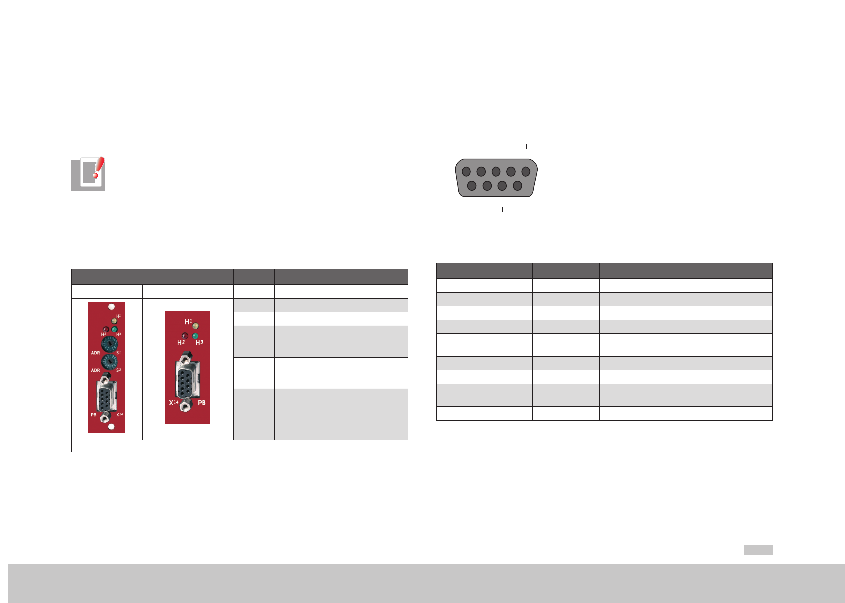
2.1. 2 Pin assignment of the D-Sub socket
PROFIBUS is connected via a nine-pin sub-D plug connector. The pin assignment is
shown in the diagram below and described in the following table.
2.1 PROFIBUS
Note:
For technical data and information on topologies and maximum cable lengths see
chapter 9.2.
2.1.1 Connections and user controls
The connections and user controls of the PROFIBUS interface are shown in table 2.1.
LEDs H1, H2, H3 act as status indicators. The rotary coding switches S1 and S2
(MSDServoDrive only) can be used to set the PROFIBUS address of the drive. The
PROFIBUS cable is connected to the D-Sub socket X14.
Front panel No. Comments
MSDServoDrive Single-Axis Compact H1 Status indicator LED (yellow)
H2 Status indicator LED (red)
H3 Status indicator LED (green)
1)
S1
1)
S2
X14 PROFIBUS cable connection
Rotary coding switch to set the
PROFIBUS address for the drive =
0x(S2)(S1)
Rotary coding switch to set the
PROFIBUS address for the drive =
0x(S2)(S1)
DGND
TxD-P
6789
RxD
VP
Figure 2.1
Pin RS-485 Signal Description
1 SHIELD Earthed shield
2 RP Reserved for power supply via bus
3 B/B’ (red) RxD / TxD-P Send and receive data (+)
4 CNTR-P Control signal for repeater (+)
5 C/C’ DGND
6 VP Power supply for terminating resistor (+)
7 RP Reserved for power supply via bus
8
9 CNTR-N Control signal for repeater (-)
Table 2.2 Description of pin assignment
Pin assignment of D-SUB connector
A/A’
(green)
RxD / TxD-N Send and receive data (-)
Data reference potential and power
supply to terminating resistor (-)
1) MSDServoDrive only
Table 2.1 PROFIBUS option card
moog
Commissioning
ID no.: CA65645-001 Date: 01/2015
The pin assignments highlighted in table 2.2 are necessary from the user’s viewpoint.
The control signals used for the repeaters are optional, and the power supply for the
terminating resistors is provided by the device.
MSD Servo Drive User Manual PROFIBUS/PROFINET
9
Page 10
Commissioning
moog
ID no.: CA65645-001 Date: 01/2015
2.1. 3 Specification of the PROFIBUS cable
For the wiring Moog recommends using the following hardware:
PROFIBUS D-Sub bus termination plug
Siemens order number 6XV1 830-0EH10
Siemens article description PB FC EIA485 PLUG 180, AXIAL CABLE OUTLET
Table 2.3 Recommended PROFIBUS D-Sub bus termination plug
PROFIBUS cable
Siemens order number 6GK1 500-0FC10
Siemens article description SIMATIC NET, PB FC STANDARD CABLE GP, 2-WIRE, SHIELDED
Table 2.4 Recommended PROFIBUS cable
2.1. 4 Bus termination
If the MSDServoDrive is initially at the end of the bus system, a plug with an integral
terminating resistor Rt should be used. In addition to the cable terminating resistor in
accordance with the EIA485 standard, a pull-down resistor Rd against the data reference
potential DGND and a pull-up resistor Ru against VP are provided. This ensures a defined
no-load potential of 1.1 Volt between pins 3 and 8. In a made-up PROFIBUS cable these
resistors are all incorporated as standard in the PROFIBUS plug and the terminating
resistor can be activated using a switch on the PROFIBUS plug. The following figure
shows a Sub-D 9-pin plug bus termination.
Vp = 5 Volt (6)
RxD TxD-P (3)
RxD TxD-N (8)
Figure 2.2
GND (6)
Unit
Sub-D 9-pin plug bus termination
MSD Servo Drive User Manual PROFIBUS/PROFINET
Ru = 390 Ohm
B (red)
Rt = 220 Ohm
A (green)
Rd = 390 Ohm
plug
PROFIBUScabel
10
Page 11
2.1.5 PROFIBUS address setting
2
1
B
C
MSDServoDrive
Select the mode of addressing:
1. Coding switches S1 and S2
By way of the two coding switches a hexadecimal address between 0 and 125
is set.
S
4
5
3
6
2
7
1
8
0
9
F
A
E
B
D
C
S
4
5
3
6
2
7
1
8
0
9
F
A
E
D
Figure 2.3 Coding switches for PROFIBUS address
2. Bus address parameter P 0918
By way of bus address parameter P 0918-COM_DP_Adress a valid decimal
address between 0 and 125 is set.
A setting via this parameter is only valid if an address above 125 is set via the
coding switches (e.g. 0xFF, i.e. S1=S2=F).
3. Setting via device keypad
A valid hexadecimal address between 0 and 125 is set using the device
keypad on the submenu "Fb". The preset value is written to bus address
parameter P0918. Instructions for use of the device keypad are given in the
MSDServoDrive Operation Manual.
A setting via the device keypad is only valid if an address above 125 is set via
the coding switches (e.g. 0xFF, i.e. S1=S2=F).
Single-Axis Compact
Select the mode of addressing:
4. Bus address parameter P 0918
By way of bus address parameter P 0918-COM_DP_Adress a valid decimal
address between 0 and 125 is set.
5. Setting via device keypad
A valid hexadecimal address between 0 and 125 is set using the device keypad
on the submenu "Fb". The preset value is written to bus address parameter
P 0918. Instructions for use of the device keypad are given in the SingleAxisCompact Operation Manual.
Note:
All setting modes require the device to be restarted in order to activate the new
address.
The following functions and displays are available:
y Display of device state
The device state is displayed when the control supply is switched on. If no input
is made via the keypad for 60seconds, the display switches back to the device
state.
y Display of device error state
If a device error occurs the display immediately switches to show the error code.
y Parameter setting (display "PA")
Reset device parameters to their factory setting
y Ethernet IP address setting (display "IP")
Set Ethernet IP address and subnet mask
y Fieldbus settings (display "Fb")
Set fieldbus address for example
2.1.6 PROFIBUS option card displays
Note:
All setting modes require the device to be restarted in order to activate the new
address.
Three LEDs are mounted on the PROFIBUS option card indicating the current operating
status of the module. The following tables set out the operating states of the PROFIBUS
option card based on the various illumination sequences.
moog
ID no.: CA65645-001 Date: 01/2015
MSD Servo Drive User Manual PROFIBUS/PROFINET
11
Commissioning
Page 12
Commissioning
moog
LED 3, green LED 2, red Status
Table 2.5 Self-test during diagnostics
LED 3, green LED 2, red Status
ID no.: CA65645-001 Date: 01/2015
Reset (after power on)
ASIC RAM test and initialisation
End of ASIC RAM test and initialisation
Seeking baud rate after power on without bus
connection
Seeking baud rate after bus connection has already
been made
Waiting for parameterisation data
Communication: Data exchange without acyclic
master class 2 connection. Yellow LED lit.
Communication: Data exchange "clear state"
Incorrect parameterisation data
MSD Servo Drive User Manual PROFIBUS/PROFINET
12
2.1.7 GSD file (PROFIBUS)
The device master data file contains the summary of the device features in a
standardised form. The device features include the device name, the bus timing, the
available extended services and the selectable modules (telegram types). In order to use
the various telegram types, the GSD file must be integrated in the configuration phase of
the PROFIBUS network. As well as the standard "Profidrive" profile, this file also contains
manufacturer-specific telegram types.
Incorrect configuration data
Communication: Data exchange with acyclic master
class 2 connection
Table 2.6 Operational diagnostics
LED 1, yellow Status
Device is exchanging data
Table 2.7 Data exchange
Page 13
2.2 PROFINET
3
Note:
For technical data and information on topologies and maximum cable lengths see
chapter 9.2.
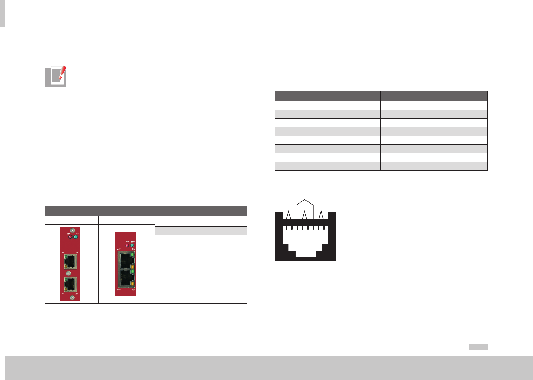
2.2.1 Connections
The connections of the PROFINET interface are shown in table 2.8. LEDs H17, H17 act
as status indicators. The PROFINET cable is connected to the RJ45 sockets X47/X48.
The two PROFINET connecting sockets are freely configurable in their communication
direction.
The PROFINET interface features a 2-port Multiport PHY (Physical Layer Transceiver)
supporting the following functionality:
− Autonegotiation (automatic detection of the functionality of the opposite
interface)
− Auto Crossing (no cross-over cables are required, so through-going wiring is
assured)
− Auto Polarity (the polarity of the Receive cable is automatically adjusted in the
event of a wiring error (RecvData+ and RecvData-))
Front panel No. Comments
MSDServoDrive Single-AxisCompact
H17 Status indicator LED (green)
H16 Status indicator LED (red)
2.2.2 Pin assignment of the RJ45 socket
The contacting of eight-pin RJ45 sockets is subject to the EIA/TIA-568A/B standards.
Table 2.9 below shows the pin assignment with the corresponding colour code for the
EIA/TIA-568B standard.
The two standards differ only in that the two wire pairs 2 and 3 are interchanged.
Pin Colour Cable wire pair Function
1 White/orange 2 TxData +
2 Orange 2 TxData -
3 White/green 3 RecvData +
4 Blue 1 Unused
5 White/blue 1 Unused
6 Green 3 RecvData -
7 White/brown 4 Unused
8 Brown 4 Unused
Table 2.9 Pin assignment of the RJ45 sockets
4
1
2
1234 5678
Table 2.8 PROFINET option card
moog
Commissioning
ID no.: CA65645-001 Date: 01/2015
X47/X48 PROFINET cable connection
Figure 2.4
RJ45 socket
MSD Servo Drive User Manual PROFIBUS/PROFINET
13
Page 14

Commissioning
moog
ID no.: CA65645-001 Date: 01/2015
2.2.3 Specification of the PROFINET cable
For the cabling Moog recommends using the following hardware:
PROFINET RJ45 connector
Siemens order number 6GK1901-1BB10-2AA0
Siemens article description
Table 2.10 Recommended PROFINET connector
PROFINET cable
Siemens order number 6XV1840-2AH10
Siemens article description
Table 2.11 Recommended PROFINET cable
IE FC RJ45 PLUG 180 2X2, RJ45 CONNECTOR
(10/100MBIT/S) WITH ROBUST METAL HOUSING &
FC CONNECTION
SIMATIC NET, IE FC TP STANDARD CABLE, GP 2X2
(PROFINET TYPE A)
MSD Servo Drive User Manual PROFIBUS/PROFINET
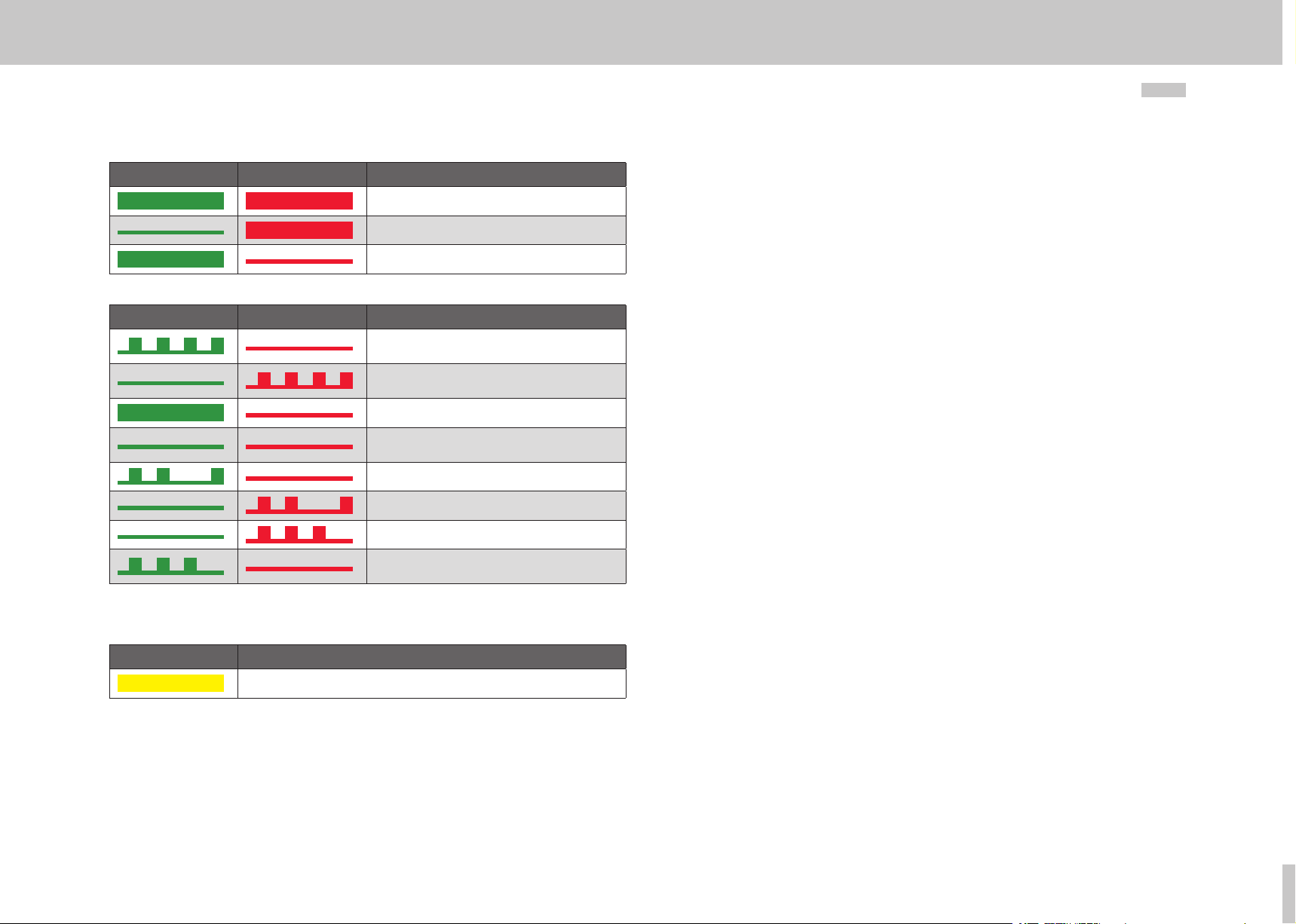
2.2.4 Meanings of LEDs
The two LEDs at the RJ45 sockets have the following meanings:
LED Function Meaning
Off = no link
No link to another device
Green Link / Activity
Yellow RUN
Table 2.12 Meanings of LEDs
On = Link
Linked to another device, no data exchange
Blinking = Activity
Data exchange active
Off = Initialisation
Device in initialisation phase
Blinking = Pre-Operational
Device in pre-operational phase
Single Flash = Safe-Operational
Device in safe operational phase
On = Operational
Device operational
14
Page 15

2.2.5 PROFINET option card displays
2.2.6 GSDML file (PROFINET)
Two LEDs are mounted on the PROFINET option card indicating the current operating
status of the module. The following tables set out the operating states of the PROFINET
option card based on the various illumination sequences.
LED H1, green LED H2, red Status
Reset (after power on)
PROFINET test and initialisation
End of PROFINET test and initialisation
Table 2.13 Self-test during diagnostics
LED H1, green LED H2, red Status
PROFINET ready, no cyclic data exchange with
PROFINET master
PROFINET ready, cyclic data exchange with
PROFINET master taking place
PROFINET software being loaded
PROFINET master flash function.
3 seconds flashing, 3 seconds lit steadily
Table 2.14 Operational diagnostics
Description of file name
y File name: GSDML-Vx.xx-Moog-MSDServoDrive-date.xml
y Vx.xx : GSDML version
y Date: Date of creation of the GSDML file
Example: GSDML-V2.25-Moog-MSDServoDrive-20120523.xml
NOTE:
The GSDML file contains the data for the MSDServoDrive (DAP2) and the SingleAxisCompact (DAP3). The required DAP (Data Access Point) must be selected
during configuration.
moog
ID no.: CA65645-001 Date: 01/2015
Commissioning
MSD Servo Drive User Manual PROFIBUS/PROFINET
15
Page 16

moog
ID no.: CA65645-001 Date: 01/2015
MSD Servo Drive User Manual PROFIBUS/PROFINET
16
Page 17
3 Cyclic data transfer
3.1 Parameter process data objects (PPOs)
Communication between a class 1 master and the MSDServoDrive is essentially
established in three phases. Firstly the MSDServoDrive is parameterised with the
current bus parameters, monitoring times and drive-specific parameters (phase 1). In
the configuration phase a configuration sent by the master is compared with the actual
MSDServoDrive configuration (phase 2). Once these two phases have been completed
successfully, the cyclic user data traffic starts (phase 3).
The various telegram types (parameter process data objects - PPOs) are made available in
the GSD file. These PPOs form the basis of the configuration phase. The project engineer
knows from the GSD file how many bytes are required for the input and output data
for PROFIBUS communication between the master and the MSDServoDrive and can
use this information to make settings in a configuration tool. As well as the standard
telegrams in accordance with the "PROFIdrive" profile, there are additionally userspecific telegram types. In addition to the process data channel PZD, some user-specific
telegrams have a parameter channel PK W.
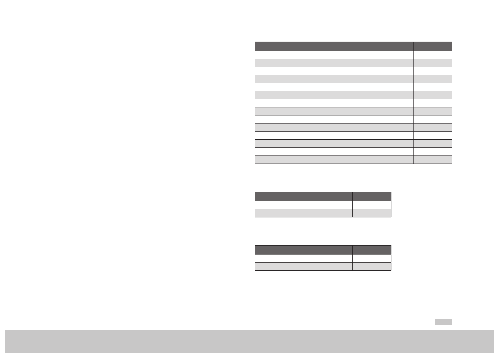
Abbreviation Designation Number of words
STW1 Control word 1 1
STW2 Control word 2 1
ZSW1 Status word 1 1
ZSW2 Status word 2 1
NSOLL_ A Rotation speed reference 1
NIST_A Actual rotation speed 1
SATZANW Set selection (from driving set table) 1
AKTSATZ Current set selection (from driving set table) 1
XSOLL_A Reference position 2
XIST_A Actual position 2
TARPOS_A Reference target position 2
VELOCITY_A Reference velocity 2
E_DIGITAL Input 1
A_DIGITAL Output 1
Table 3.1 Abbreviations
Standard telegram 1 is a defined telegram type for speed control. It consists of two input
words and two output words as shown in the following table.
3.1.1 Standard "PROFIdrive" telegrams
The table below firstly lists the standard PROFIdrive telegrams supported by the
MSDServoDrive. The following table explains the abbreviations assigned in the standard
telegrams to specific process data channels. The process data channel (abbreviated as
PZD) is grouped word-by-word.
moog
ID no.: CA65645-001 Date: 01/2015
Cyclic data transfer
PZD number 1 2
Reference values STW1 NSOLL_ A
Actual values ZSW1 NIST_A
Standard telegram 7 is a defined telegram type for driving set selection. There are a total
of 16 driving sets available for selection in the drive. This telegram type consists of two
input words and two output words as shown in the following table.
PZD number 1 2
Reference values STW1 SATZANW
Actual values ZSW1 AKTSATZ
MSD Servo Drive User Manual PROFIBUS/PROFINET
17
Page 18

Cyclic data transfer
moog
ID no.: CA65645-001 Date: 01/2015
Standard telegram 8 is a defined telegram type for positioning with the option to preset
a positioning velocity. It consists of five input words and five output words as shown in
the following table.
PZD number 1 2 3 4 5
Reference values XSOLL_A STW2 NSOLL_A
Actual values XIST_A ZSW2 NIST_A
Standard telegram 9 is a defined telegram type for positioning. It consists of six input
words and five output words as shown in the following table.
PZD number 1 2 3 4 5 6
Reference values STW1 TARPOS_A STW2 V ELOCITY_ A
PZD number 1 2 3 4 5
Actual values ZSW1 XIST_A ZSW2 NIST_A
Table 3.2 Standard telegram 9
MSD Servo Drive User Manual PROFIBUS/PROFINET
18
Every standard telegram in the device is described in the GSD or GSDML file as
appropriate by a configuration identifier (ID) based on the PROFIdrive profile. The
following table lists these identifiers for the selected standard telegrams.
Telegram type
Standard telegram 1
Standard telegram 7
Standard telegram 8
Standard telegram 9
Table 3.3 Identifiers
Data range Identifier (ID) Module ID IRT module ID
2 output words
and 2 input words
2 output words
and 2 input words
5 output words
and 5 input words
6 output words
and 5 input words
PROFIBUS PROFINET
0xC3 0xC1 0xC1
0xFD 0x00 0x01
0xC3 0xC1 0xC1
0xFD 0x00 0x07
0xC3 0xC4 0xC4
0xFD 0x00 0x08
0xC3 0xC5 0xC4
0xFD 0x00 0x09
0x01 0x0101
0x07 0x0107
0x08 0x0108
0x09 0x010 9
Page 19

3.1. 2 User-specific PPOs
As well as the supported standard telegrams, there are additional user-specific
parameter process data objects (PPOs). The following PPOs are also transmitted cyclically
and in addition to the process data channel PZD in some instances contain a parameter
channel PKW enabling access to the drive parameter values.
PPO PKW PZD
1 PKE IND PKW
1
2 PKE IND PKW
1
3* - - - - STW/
4 - - - - STW/
5 PKE IND PKW
1
- - - - STW/
PKE IND PKW
1
- - - - STW/
PKE IND PKW
1
- - - - STW/
(*) PPO3 is the standard tele gram 1
Table 3.4 User-specific parameter process data objects
PKW
2
PKW
2
PKW
2
PKW
2
PKW
2
STW/
ZSW
STW/
ZSW
ZSW
ZSW
STW/
ZSW
ZSW
STW/
ZSW
ZSW
STW/
ZSW
ZSW
REFERENCE/
ACTUAL
REFERENCE/
ACTUAL
REFERENCE/
ACTUAL
REFERENCE/
ACTUAL
REFERENCE/
ACTUAL
REFERENCE/
ACTUAL
REFERENCE/
ACTUAL
REFERENCE/
ACTUAL
REFERENCE/
ACTUAL
REFERENCE/
ACTUAL
- - - - - - - -
PZD
3
- - - - - - - -
PZD
3
PZD
3
PZD
3
PZD
3
PZD
3
PZD
3
PZD
3
PZD
4
PZD
4
PZD
4
PZD
4
PZD
4
PZD
4
PZD
4
PZD
4
PZD
5
PZD
5
PZD
5
- - - - - -
- - - - - -
PZD
5
PZD
5
PZD
5
PZD
6
PZD
6
PZD
6
PZD
6
PZD
6
PZD
6
- - - -
- - - -
PZD
7
PZD
7
PZD
7
PZD
7
PZD
8
PZD
8
PZD
8
PZD
8
PZD
9
- -
- -
PZD
9
PZD
10
PZD
10
moog
ID no.: CA65645-001 Date: 01/2015
Cyclic data transfer
MSD Servo Drive User Manual PROFIBUS/PROFINET
19
Page 20
Cyclic data transfer
moog
In the drive parameter list there are two signal tables containing all the process data
that can be cyclically read and written for the PROFIBUS communication DPV0. All
possible writeable process data signals can be found in signal table P 1284 (COM_DP_
SignalList_Write) and all possible readable process data signals can be found in signal
table P 1284 (COM_DP_SignalList_Read). The most important readable and writeable
parameters are also documented in chapter 6.
The writeable process data signals can be configured in signal table S 0915 (COM_DP_
PZDSelectionWrite). The available number of writeable process data items is determined
by the selected PPO type.
The readable process data signals can be configured in signal table S 0915
(COM_DP_PZDSelectionRead). The available number of readable process data items is
likewise determined by the selected PPO type.
When using standard telegrams, the process data signals in the signal tables are
automatically configured by the firmware.
Note:
The content of this column applies only to PROFIBUS.
A maximum of 15 process data signals can be mapped. Both single and double words
can be used.
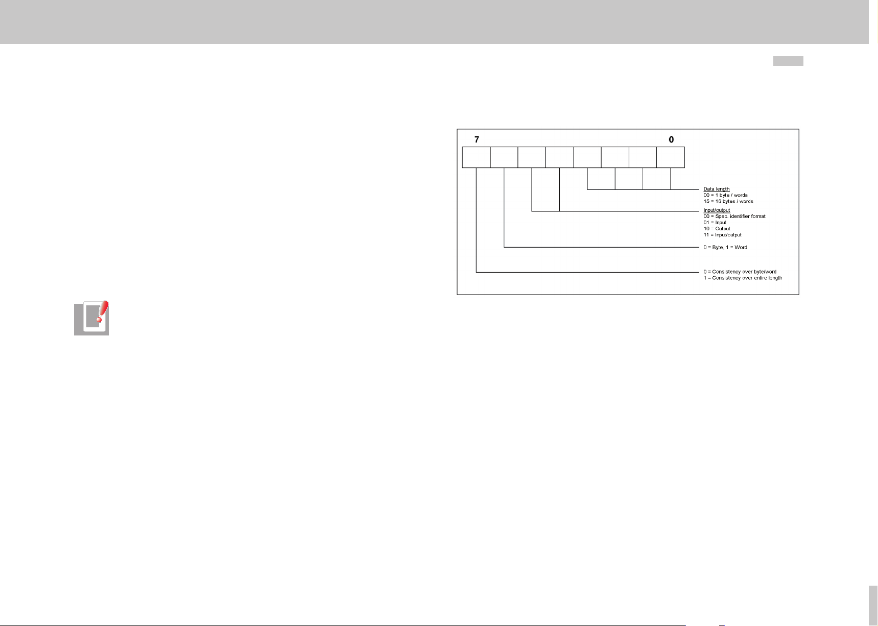
The user-specific drive telegram types are described by a configuration identifier (ID)
in the GSD file. This describes the structure of the cyclic user data based on a special
identifier format shown in the diagram below.
ID no.: CA65645-001 Date: 01/2015
MSD Servo Drive User Manual PROFIBUS/PROFINET
Figure 3.1 Identifier format
After the parameterisation phase, the master sends the drive a configuration telegram
containing this special identifier (ID). On receipt of this, the drive compares the data
in the configuration telegram with the configuration held in the drive. The identifier
determined by the PPO type can be found in the GSD file under the heading "Modules".
The following table shows these identifiers for the user-specific telegrams.
20
Page 21

PPO
type
1
2
3 0xF1 0x67 0x167 2 words input/output data (consistent overall length) PZD channel
4 0xF5 0x68 0x168 6 words input /output data (consistent overall length) PZD channel
5
Table 3.5 Listing of identifiers
PROFIBUS
identifier
(ID) Hex
0xF3
0xF1
0xF3
0xF5
0xF3
0xF9
0xF3 0x6A 0x16A 4 words input/output data (consistent overall length) PZD channel
0xF3
0xF3
0xF7 0x6C 0x16C 8 words input /output data (consistent overall length) PZD channel
0xF3
0xF7
0xF9 0x6E 0x16E 10 words input/output data (consistent overall length) PZD channel
0xC0
0xCD
0xCD
0xF3
0xC0
0xCD
0xCD
0xC0
0xD1
0xD1
0xF3
0xC0
0xD1
0xD1
0xC0
0xD5
0xD5
PROFINET
module ID
0x65 0x165
0x66 0x166
0x69 0x169
0x6B 0x16B
0x6D 0x16D
0x6F 0x16F 14 words input/output data (consistent overall length) PZD channel
0x70 0x170
0x71 0x171 18 words input/output data (consistent overall length) PZD channel
0x72 0x172
0x73 0x17 3 22 words input/output data (consistent overall length) PZD channel
PROFINET
IRT module ID
Evaluation by special identifier format (figure 3.6)
Slave-Master
4 words input/output data (consistent overall length)
2 words input/output data (consistent overall length)
4 words input/output data (consistent overall length)
6 words input/output data (consistent overall length)
4 words input/output data (consistent overall length)
10 words input/output data (consistent overall length)
4 words input/output data (consistent overall length)
4 words input/output data (consistent overall length)
4 words input/output data (consistent overall length)
8 words input/output data (consistent overall length)
4 words input/output data (consistent overall length)
14 words input/output data (consistent overall length)
4 words input/output data (consistent overall length)
18 words input/output data (consistent overall length)
Referred to
Table AK
PKW channel
PZD channel
PKW channel
PZD channel
PKW channel
PZD channel
PKW channel
PZD channel
PKW channel
PZD channel
PKW channel
PZD channel
PKW channel
PZD channel
moog
ID no.: CA65645-001 Date: 01/2015
Cyclic data transfer
MSD Servo Drive User Manual PROFIBUS/PROFINET
21
Page 22

Cyclic data transfer
moog
PPO
type
Table 3.5 Listing of identifiers
PROFIBUS
identifier
(ID) Hex
0xDD
0xDD
0xDD
0xDD
ID no.: CA65645-001 Date: 01/2015
0xC0
0xD9
0xD9
0xF3
0xC0
0xD9
0xD9
0xF3
0xC0
0xC0
MSD Servo Drive User Manual PROFIBUS/PROFINET
PROFINET
module ID
0x75 0x175 26 words input/output data (consistent overall length) PZD channel
0x76 0x176
0x78 0x178
0x77 0x17 7 32 words input/output data (consistent overall length) PZD channel
PROFINET
IRT module ID
Evaluation by special identifier format (figure 3.6)
4 words input/output data (consistent overall length)
26 words input/output data (consistent overall length)
4 words input/output data (consistent overall length)
32 words input/output data (consistent overall length)
Referred to
Table AK
Slave-Master
PKW channel
PZD channel
PKW channel
PZD channel
22
Page 23

3.1. 3 Parameter channel PKW
Some PPOs offer an additional cyclic parameter channel. This channel allows drive
parameters to be read and written.
PKW
1. By te 2. Byte 3. Byte 4. Byte 5. Byte 6. Byte 7. Byte 8. Byte
PKE (1 word) IND (1 word) PKW1 (1 word) PKW2 (1 word)
The parameter consists of a total of four words: the parameter identifier PKE (1 word),
the subindex IND (1 word) (subindex 0 in the parameter must be addressed with 1) and
the parameter identifier value, which occupies the data range PKW1 (1 word) to PKW2
(1 word). The parameter identifier is represented bit-by-bit in the following table.
AK PNU
15 14 13 12 11 10 9 8 7 6 5 4 3 2 1 0
AK
PNU
Table 3.6 Parameter identifier PKE
The following tables list the request (master) and response (slave) identifiers.
Request identifier Function
Table 3.7 Request identifier AK (Master Slave)
Request or response identifier (value range 0..15)
Parameter number (value range 1…4095)
0 No request
1 Request parameter value
2 Change parameter value (word)
3 Change parameter value (double word)
4 Read parameter description
5 -
6 Request parameter value (array)
7 Change parameter value (array) (word)
8 Change parameter value (array) (double word)
Request identifier Function
0 No response
1 Parameter value sent (word)
2 Parameter value sent (double word)
3 Parameter description sent
4 Parameter value (array) sent (word)
5 Parameter value (array) sent (double word)
6 -
7 Request not executable, see error no.
Table 3.8 Response identifier AK (Slave Master)
In the case of response identifier 7 the error number sent to the drive from the master is
shown in the range PKW1 to PKW2. The following table explains these error numbers.
Error Statement
0 Impermissible PNU
1 Parameter cannot be changed
2 Lower or upper parameter value limit transgressed
3 Defective sub-index
4 Not an array
5 Incorrect data type
...
17 Request cannot be executed because of the operating status
18 Other error
Table 3.9 Response identifier AK (Slave Master)
Request identifier 4 can additionally be used to read a parameter description. The
parameter description contains relevant information on the parameter concerned.
Thefollowing table shows the subindices that can be used to access the individual
parameter structure elements. The subindex is preset only by byte 3.
moog
ID no.: CA65645-001 Date: 01/2015
Cyclic data transfer
MSD Servo Drive User Manual PROFIBUS/PROFINET
23
Page 24

Cyclic data transfer
moog
Sub-index Meaning Data type
1 Identifier (ID) V2
2 Number of field elements or string length Unsigned 16
3 Standardisation factor Floating point
4 Variable attributes Octet string 2
5 Reserved Octet string 4
6 Name (only the first four bytes are sent) Visible string 16
7 Lower limit value Octet string 4
8 Upper limit value Octet string 4
9 Reserved Octet string 2
10 ID extension Extension V2
11 PZD reference parameter Unsigned 16
12 PZD standardisation V2
Table 3.10 Parameter description
ID no.: CA65645-001 Date: 01/2015
The identifier (subindex 1) in the parameter description identifies additional characteristics
of the parameter concerned. Table 3-8 sets out the meaning of the identifier.
Bit Meaning Explanation
15 Reserved
14 Array
13 Parameter value can only be reset If this bit is set, the relevant parameter value
12 Parameter value was changed to a value
different from the factory settings
11 Reserved
10 Additional text array can be called up
9 Parameter cannot be written
8 Standardisation factor and variable
attributes not relevant
0 - 7 Data type of the parameter value (value =
"Profi-Drive table 9")
Table 3.11 Identifier syntax
can be varied externally only so as to be set
to zero.
If this bit is set, the parameter value is
different from the factory setting.
This bit is set if the parameter is of a data
type that cannot be used to calculate any
physical values (e.g. data type string)
MSD Servo Drive User Manual PROFIBUS/PROFINET
24
3.2 Monitoring
The MSDServoDrive provides two options for monitoring cyclic communication.
3.2.1 Watchdog
Parameter P 1283 (COM_DP_BUS_Timeout) can be used to configure a watchdog.
Parameter
No.
P 1283 COM_DP_BUS_Timeout
Table 3.12 Watchdog
The watchdog is activated after the first cyclic telegram, and in the event of an error
triggers error (32-1) if no cyclic telegrams are received in the time defined by parameter
P 1283 (COM_DP_BUS_Timeout).
The value 0 in parameter P 1283 (COM_DP_BUS_Timeout) deactivates the function.
3.2.2 Sign of Life
The Sign of Life function is implemented as per Profidrive profile 4.1.
Parameter No. Name Meaning
P 0925 COM_PN_Sign_of_life_limit
P 1296 COM_PN_Sign_of_life_err_cnt Display of current error counter
P 1280 Control word 2 Bit 12-15 Sign of Life master
P 1281 Status word 2 Bit 12-15 Sign of Life slave
Table 3.13 Sign of Life
The Sign of Life function can be deactivated with the value 0xFFFF in parameter P 0925
(COM_PN_Sign_of_life_limit) (factory setting).
Name Meaning Data type Unit
Watchdog for cyclic
communication
Number of approved SOL (Sign of Life) errors
until error shutdown
type U16: 0 – 0xfffe, 0xffff = switch off
INT32 (0 – 4294967295) ms
Page 25

The function is activated when the first cyclic telegram is received in which bits 12-15 of
the second control word (1280) are not equal to 0. When the function is activated, the
error counter parameter P 1296 (COM_PN_Sign_of_life_err_cnt) is set to 0.
With each newly received telegram the counter (bits 12-15) in the second status word
parameter P 1281 (COM_DP_Statusword2) is incremented by the value 1.
In each cycle the status counter is compared with the counter in the second control
word. If that counter is not equal, the error counter parameter P 1296 (COM_PN_Sign_
of_life_err_cnt) is incremented by the value 10. If the counters in the second control
word and second status value are equal, the error counter parameter P 1296 (COM_PN_
Sign_of_life_err_cnt) is decremented by the value 1. The error counter cannot fall below
0.
If the error counter parameter P 1296 (COM_PN_Sign_of_life_err_cnt) is greater
than or equal to 10 * parameter P 0925 (COM_PN_Sign_of_life_limit) the error message
(32-03 Profinet IRT: Sign of Life error) is triggered and bit 4 in parameter P 0953
(COM_DP_Warning) is set.
If cyclic transfer is interrupted and then re-established, the error counter parameter
P 1296 (COM_PN_Sign_of_life_err_cnt) is cleared and the warning bit 4 in parameter
P 0953 (COM_DP_Warning) is reset.
Normal operation Sign of Life
Figure 3.2 Normal operation Sign of Life
moog
ID no.: CA65645-001 Date: 01/2015
Cyclic data transfer
MSD Servo Drive User Manual PROFIBUS/PROFINET
25
Page 26

Cyclic data transfer
moog
ID no.: CA65645-001 Date: 01/2015
3 Sign of Life errors triggered
Figure 3.3 3 Sign of Life errors triggered
The value of the master is not increased in three cycles. The error counter is increased by
the value 10 in each of these cycles. When the master generates the Sign of Life again,
the error counter is decreased by the value 1 in each cycle.
MSD Servo Drive User Manual PROFIBUS/PROFINET
26
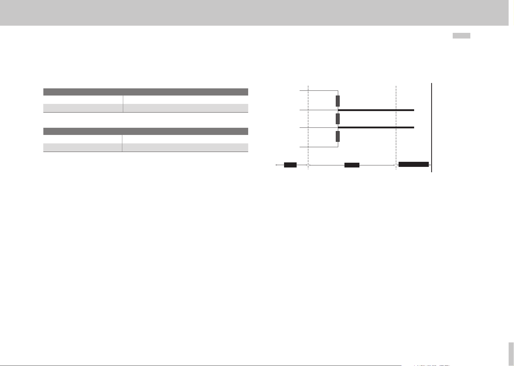
4 Sign of Life errors triggered with error reaction
Figure 3.4 4 Sign of Life errors triggered with error reaction
The value of the master is not increased in four cycles if a value 4 is entered in
parameterP 0925 (COM_PN_Sign_of_life_limit). The error counter is increased by the
value10 in these cycles. When the error counter reaches the maximum value (40),
theerror reaction is triggered.
Page 27

4 Acyclic data transfer
The PROFIdrive profile includes the "Base Mode Parameter Access" model for this. It is
used for both PROFIBUS and PROFINET.
Acyclic
services
Write request 1 Write request via DPV1 33 33H
Alarm 1 Interrupt handling 33 33H
Table 4.2 Overview of acyclic services offered
Master
class
Meaning DSAP SSAP
4.1 PROFIBUS parameter access
In addition to cyclic data communication, which is intended as the default for quick
updating of I/O process data, acyclic services are offered for one-off events. They offer
the facility to read or write parameters acyclically, for example, so as not to impede
cyclic data traffic. Telegram type SD2 as set out in the following table is used for the
PROFIBUS-DP extension DPV1.
SD LE LEr SD DA SA DSAP SSAP DU FCS ED
Start
Delimiter
The acyclic services can be used by a class 1 master (PLC etc.) and by a class 2 master
(PC tool). The following table gives an overview of the acyclic services available in
relation to the respective master class.
Length Length
repeat
68H X X 68H xx xx xx xx X..
Table 4.1 PROFIBUS SD2 telegram for DPV1 services
Acyclic
services
Initiate request 2 Establish an acyclic connection 32H 31H
Abort request 2 Break off an acyclic connection 32H 0..30H
Read request 2 Read request via DPV1 32H 0..30H
Write request 2 Write request via DPV1 32H 0..30H
Data request 2 Data transfer 32H 0..30H
Read request 1 Read request via DPV1 33 33H
Start
Delimiter
Master
class
Destination
Address
Source
Address
Destination
Service
Access
Point
Meaning DSAP SSAP
Source
Service
Access
Point
Data
Unit
Frame
Check
Sequence
End
Delimiter
DPV1 is always accessed according to a fixed mechanism:
1. Write request (5F):
SD .. DSAP SSAP
68H xx 32 30 5F 0 2F n+1 0..n xx 16H
DU
Req. id
2. Write response (5F):
SD .. DSAP SSAP
68H xx 32 30 5F 0 2F n+1 xx 16H
DU
Req. id
3. Read request (5E):
SD .. DSAP SSAP
68H xx 32 30 5E 0 2F MAX xx 16H
DU
Req. id
4. Read response (5E):
SD .. DSAP SSAP
68H xx 32 30 5E 0 2F n+1 0..n Xx 16H
DU
Req. id
Each read or write access must first be initiated by a write service on Data Unit Index 47
(2Fhex) (1). This write request gives the slave the information about the request it is to
execute. After this the slave acknowledges with a response telegram (2), which initially
contains no response data.
DU
Slot
DU
Slot
DU
Slot
DU
Slot
DU
Index
DU
Index
DU
Index
DU
Index
DU
Length
DU
Length
DU
Length
DU
Length
DU
DU
FCS ED
FCS ED
User
FCS ED
FCS ED
User
moog
ID no.: CA65645-001 Date: 01/2015
Acyclic data transfer
MSD Servo Drive User Manual PROFIBUS/PROFINET
27
Page 28

Acyclic data transfer
moog
This is simply an acknowledgement of the request and contains only the mirrored
DPV1 header of the request telegram. In the event of an error, a negative response is
sent. To then read the data from the slave, the master must present a read request (3).
If the response (4) to this is positive, the user data can be used by the master. In the
event of an error, a negative response is sent. The "DPV1 read request" diagram shows
the telegram sequence for read access. This shows the slave sending a negative read
response to the first read request. This negative read response means that the required
data cannot yet be provided.
Not until the following cycle has the slave executed the request to the extent that it can
send a positive read response with the requested data.
Figure 4.1 DPV1 read request
This transfer format is "Big Endian" (Motorola, the highest byte is transmitted first).
ID no.: CA65645-001 Date: 01/2015
MSD Servo Drive User Manual PROFIBUS/PROFINET
28
Word format:
0. Byte 1. Byte
High byte Low byte
Double word format
0. Byte 1. Byte 2. Byte 3. Byte
High byte
High word
The data unit in the table "PROFIBUS SD2 telegram for DPV1 services" of telegram type
SD2 can be split into five areas:
y Req.id (1 byte)
This is the function number of the DPV1 service. This describes, for example,
whether a parameter is to be read or written. More detailed information can be
found in the table headed "Data unit assignment".
y Slot (1 byte)
DPV1 slaves consist of a number of physical or virtual slots. The drive is
triggered by addressing a slot, following which the slot address is not evaluated.
y Index (1 byte)
The index contains the address of the data area in which the slave makes
available the data for parameter access. In accordance with ProfiDrive this is
specified with the fixed data area number 47.
y Length (1 byte)
Indicates the length of the user data that follow. In the case of a read access,
the length must be sufficiently large for the data to be read (max. 240 bytes)
User (1 byte…N bytes) Contains the user data to be processed
Low byte
High word
High byte
Low word
Low byte
Low word
Page 29

Data Unit (DU)
Byte
0 Req.id 48H Idle REQ, RES Idle REQ, RES
RES
1 Slot 00H..FEH Slot number
2 Index 2FH Index
3 Length xx Length of user data (max. 240 bytes)
4..n UserData xx User data
[Alarms are not currently supported]
Table 4.3 Data unit assignment
Data Unit
Param
Value Meaning
51H Data Transport REQ,
RES
56H Resource Manager,
REQ
57H Initiate REQ, RES Initiate REQ, RES
58H Abort REQ Abort REQ
5CH Alarm REQ, RES Alarm REQ, RES
5EH Read REQ, RES Read REQ, RES
5FH Write REQ, RES Write REQ, RES
D1H Data Transport NEG
RES
D7H Initiate NEG RES Initiate negative RES
DCH Alarm NEG RES Alarm negative RES
DEH Read NEG RES Read negative RES
DFH Write NEG RES Write negative RES
Data transport REQ,
Resource manager REQ
Data transport negative
RES
4.2 PROFINET parameter access
In the case of PROFINET the acyclic services are executed by way of the "Record Data CR
(connection relationsship)". There are read and write commands for the purpose.
Master Slave
Parameter request "Write Data Record" with index
0xB02E
Parameter request "Read Data Record" with index
0xB02E
Read response OK or error message (0xDF)
Write response OK or error message (0xDE)
4.3 "Base Mode Parameter Access" data format
The following table sets out the telegram format of parameter access for a parameter
request and response.
Base mode parameter
request
Request
header
1st parameter address
nth parameter address
Table 4.4 Data unit assignment
Request reference Request identification 0
Axis No No. of Parameters (n) 2
Attribute No. of elements 3
Parameter Number (PNU)
Subindex
..... 4+6*(n-1)
Format No. of values 4+6*n
Values
...
... ...
Byte address
4+ 6*n +…+
(format_n
*amount_n)
moog
ID no.: CA65645-001 Date: 01/2015
Acyclic data transfer
MSD Servo Drive User Manual PROFIBUS/PROFINET
29
Page 30

Acyclic data transfer
moog
Base mode parameter
response
Response
header
1st parameter value
nth parameter value ... ...
Table 4.5 Parameter response
ID no.: CA65645-001 Date: 01/2015
Request reference
(mirror)
Axis No (mirror) No. of Parameters (n) 2
Format No. of values 4
Value / error code
...
The user data are structured as follows:
y Request reference:
The request reference is specified by the master and mirrored back by the slave
in the response telegram. Based on this reference the master can uniquely
assign each response telegram to a request telegram. A master changes the
request reference with each new request.
y Request ID
This identifier essentially describes how the parameter is handled. Currently two
different identifiers are defined:
- Request parameter
- Change parameter
For more details on the identifier refer to the "User data" table.
y Response ID
This identifier contains information on the origin of a request. If a request is
executed correctly, the response ID matches the request ID. If a request cannot
be executed, an identifier from the "User data" table is generated.
y Axis No.
This value allows single axes in a multi-axis system to be addressed selectively
(Axis No. 0 = single axis).
y No. of Parameters
Number of parameters processed in a request.
Response identification 0
Byte address
4+…+
(format_n
*amount_n)
MSD Servo Drive User Manual PROFIBUS/PROFINET
y Attribute
Describes the individual access to a parameter structure. For example, whether
access to the actual numerical value or to the parameter description text is
desired. Further information can be found in the "User data" table.
y Number of Elements
When accessing an array or a string, this area contains the field size or string
length as appropriate.
y Parameter Number
Contains the parameter number (PNU).
y Subindex
Addresses the first array element of a parameter or the beginning of a character
string. This also allows addressing of description texts and text arrays.
y Format
Specifies the relevant parameter and ensures unique assignment of the
parameter value in the telegram.
y Number of values
Number of following values
y Values
Parameter values
30
Page 31

Field name Data type Value Meaning Comments
Field name Data type Value Meaning Comments
Request reference
Request ID Unsig-
Response ID Unsig-
Axis No Unsig-
No. of Parameters
Attribute Unsig-
No. of Elements Unsig-
Parameter
Number
Subindex Unsig-
Table 4.6 User data
Unsigned8
ned8
ned8
ned8
Unsigned8
ned8
ned8
Unsigned16
ned16
0x00
0x01..0xFF
0x00
0x01
0x02
0x03..0x03F
0x40..0x7F
0x80..0xFF
0x00
0x01
0x02
0x03..0x3F
0x40..0x7F
0x80
0x81
0x82
0x83..0xBF
0xC0..0xFF
0x00
0x01..0xFE
0xFF
0x00
0x01..0x27
0x28..0xFF
0x00
0x10
0x20
0x30
0x40..0x70
0x80..0xF0
0x00
0x01..0xEA
0xEB..0xFF
0x0000
0x0001…
0xFFFF
0x0000…
0xFFFF
Reserved
Reserved
Request parameter
Change Parameter
Reserved
Manufacturer-specific
Reserved
Reserved
Request parameter (+)
Change Parameter (+)
Reserved
Manufacturer-specific
Reserved
Request parameter (-)
Change Parameter (-)
Reserved
Manufacturer-specific
Device Representative
Axis-Number 1..254
Reserved
Reserved
Quantity 1..39
Reserved
Reserved
Value
Description
Tex t
Reserved
Manufacturer-specific
Special Function
Quantity 1..234
Reserved
Reserved
Number 1..65535
Number 1..65535
Zero = single axis
Limited
by DPV1
Telegram length
Limited
by DPV1
Telegram length
Field name Data type Value Meaning Comments
Format Unsig-
ned8
No. of Values Unsig-
ned8
Error Number Unsig-
ned16
Table 4.6 User data
0x00
0x01..0x36
0x37..0x3F
0x40
0x41
0x42
0x43
0x44
0x45..0xFF
0x00..0xEA
0xEB..0xFF
0x0000…
0x00FF
Reserved
Data Types
Reserved
Zero
Byte
Word
Double Word
Error
Reserved
Quantity 0..234
Reserved
Error Numbers
(see table below)
Limited
by DPV1
Telegram length
Error number Meaning
Error number Meaning
0x00 Impermissible parameter number
0x01 Parameter value cannot be changed
0x02 Value area of the parameter transgressed
0x03 Defective parameter sub-index
0x04 Parameter is not an array
0x05 Incorrect parameter data type
0x06 Change access with value not equal to zero, which is not permitted
0x07 Change access on a descriptive element, which cannot be changed
0x09 No descriptive text available
0x11 Request cannot be performed in the present system status
0x14 Impermissible value
0x15 Reply telegram is too long
0x16 Impermissible parameter address
0x17 Illegal format
0x18 Number of parameter values is inconsistent
0x19 Request for a non-existent axis
Table 4.7 Error numbers
moog
ID no.: CA65645-001 Date: 01/2015
Acyclic data transfer
MSD Servo Drive User Manual PROFIBUS/PROFINET
31
Page 32

Acyclic data transfer
moog
ID no.: CA65645-001 Date: 01/2015
4.4 Examples of request and response telegrams
Write word
Req.
Re-fer.
ID
0 2 0 1 0x10 0..1 3 0x96 0 0 0x42 1 0 7
Table 4.8 ID:2 Change Parameter, Attr. 0x10: value; PNU = P 0918 = 0x396, format word=0x42
Positive response
Refer.
0 2 0 1
Table 4.9 ID:2 Change Parameter
y Parameter P 0918 now has the value 7
Write double word
Refer. Req.
0 2 0 1 0x10 0..1 4 0xFA
Sub high Sub low Format No.
0 0 0x43 1 1 2 3 4
Table 4.10 ID:2 Change Parameter, Attr. 0x10: value; PNU = P 0918 = 0x396, format
No.
Axis
Pa-
ram.
Req.
ID
ID
word=0x42
No.
Ele.
PNU
high
ram.
Values
Attr.
Axis No. Param.
Axis No. Pa-
PNU
Sub
Sub
low
high
Attr. No. Ele. PNU high PNU low
Value
high
low
Value
low
Format
No.
Values
Value l
high
Value
high
Value l
low
Value
low
MSD Servo Drive User Manual PROFIBUS/PROFINET
Read simple parameter value
Read word
Refer.
Table 4.12 ID:1 Request Parameter, Attr. 0x10: value; PNU = P 0922 = 0x39A
Req.
0 1 0 1 0x10 0 ..1 3 0x9A 0 0
ID
Axis
Positive response
Refer.
Table 4.13 Format word=0x42; parameter value = 9
Req.
0 1 0 1 0x42 1 0 9
ID
Axis
Read double word
Refer.
Table 4.14 ID:1 Request Parameter, Attr. 0x10: value; PNU = P 1274 = 0x4FA
Req.
0 1 0 1 0x10 0 ..1 4 0xFA 0 0
ID
Axis
Positive response
Refer.
Table 4.15 Format dword=0x43; parameter value = 0x01020304 = 16909060
Req.
0 1 0 1 0x43
ID
Axis
No.
Param.
No.
Param.
No.
Param.
No.
Param.
Attr.
Format
Attr.
Format
No.
Ele.
No
values
No.
Ele.
No
values
Pnu
high
Value
high
Pnu
high
Value
H high
Pnu
Low
Value
low
Pnu
Low
Value
H Low
Sub
high
Sub
high
Value
l high
32
Sub
low
Sub
low
Value
l low
Refer.
0 2 0 1
Table 4.11 ID:2 Change Parameter
Req.
ID
Axis No. Param.
y Parameter 884 now has the value 16909060
Error access
Erroneous parameter number
Refer.
Table 4.16 ID:1 Request Parameter, Attr. 0x10: value; PNU = 9
Req.
0 1 0 1 0x10 0 ..1 0 9 0 0
ID
Axis
No.
Param.
Attr.
No.
Ele.
Pnu
high
Pnu
Low
Sub
high
Sub
low
Page 33

Negative response
Refer.
Table 4 .17 Format error=0x44; parameter value = 0 = incorrect parameter
Req.
0 0x81 0 1 0x44 1 0 0
ID
number
Axis
No.
Param.
Format
No
values
Value
high
Value
low
Write parameter values array
Refer.
0 2 0 1 0x10 5 3 0x93 0 0 0x42 5 3 C7 0 0
Table 4.18 ID:2 Change Parameter, Attr. 0x10: value; PNU = P 0918 = 0x396, format word=0x42
Req.
ID
Axis
y Parameter values = 0x03C7, 0x04F6, 0x04F6, 0x04F6, 0
No.
Param.
Attr. No. Ele. PNU high PNU low Sub high Sub low Format
No.
Values
Value 0
high
Value 0
Low
Value 4
high
OK response
Refer.
Req.
0 2 0 1
ID
Axis
y Parameter P 0915 now contains the entries for the parameter values.
y No standard telegram smaller than 10 may set up in the device,
because then it could not be overwritten; as a remedy set PPO5.
No.
Param.
Value 4
low
moog
ID no.: CA65645-001 Date: 01/2015
Acyclic data transfer
MSD Servo Drive User Manual PROFIBUS/PROFINET
33
Page 34

Acyclic data transfer
moog
ID no.: CA65645-001 Date: 01/2015
MSD Servo Drive User Manual PROFIBUS/PROFINET
Read parameter values array
Read assigned process data reference values
Refer.
Table 4.19 ID:1 Attr. : 0x10 PNU = P 0 915=0x393
Req.
0 2 0 1 0x10 5 3 C7 0 0
ID
Axis
OK response
Refer.
0 1 0 1 0x42 5 3 0xC7 4 0xF6 4 0xF6 5 0 0 0
Table 4.20 ID: 1 Format: 0x42
Req.
ID
Axis
No.
Param.
Attr. No. Ele.
No.
Param.
Format
Value 0
high
No
Values
Value 0
Low
Value 0
high
Value 4
high
Value 4
low
Value 0
low
Value 1
high
Value 1
Low
Value 2
high
Value 2
Low
Value 3
high
Value 3
Low
Value 4
high
34
Value 4
low
Page 35

5 Profidrive operation modes
5.1 Profinet operation modes
The devices of the MSDServoDrive families support the following operation modes:
y Speed control jog mode
y Position control jog mode
y Speed control (application class 1)
y Position control (application class 3)
y Position control (interpolating mode)
Operation modes are selected by standard telegram selection in the master or by using
free telegrams and configuring the following parameters:
Parameter No. Name Meaning
P 0300 CON_CfgCon Set control mode
P 0301 CON_REF_Mode Set reference profiles
Table 5.1 Watchdog
moog
ID no.:CA65645-001 Date: 01/2015
Profidrive operation modes
MSD Servo Drive User Manual PROFIBUS/PROFINET
35
Page 36

Profidrive operation modes
moog
ID no.:CA65645-001 Date: 01/2015
5.1.1 Speed control circuit and associated control parameters
Figure 5.1 Speed control loop
P.no.: Parameter name Meaning
P 0167 MPRO_REF_OVR Velocity override
P 0320 CON_SCON_Kp PI speed controller gain
P 0321 CON_SCON _Tn PI_speed controller integral-action time
P 0325 CON_SCONFilterFreq Limit frequencies for torque reference value filter
P 0326 CON_SCONFilterAssi Torque reference value filter draft parameter
P 0327 CON_SCONFilterPara Torque reference filter parameter
P 0328 CON_SCON_SMax Speed limit (reference variable: motor nominal speed)
P 0330 CON_SCON_TMaxNeg Negative torque limit (reference variable: nominal torque)
P 0331 CON_ SCON_TMaxPos Positive torque limit (reference variable: nominal torque)
P 0332 CON_SCON_TMaxScale Torque scaling factor
P 0333 CON_SCON_SMaxNeg Negative speed limitation (reference value: motor
P 0334 CON _SCON_SMaxPos Positive speed limitation (reference value: motor nominal
P 0339 CON _SCON_Tmax Torque limitation (reference value: nominal torque)
nominal speed)
speed)
MSD Servo Drive User Manual PROFIBUS/PROFINET
P.no.: Parameter name Meaning
P 0351 CON_SCALC_TF Actual speed filter time constant
P 0371 CON_IP_RefTF Speed reference filter time constant
P 0401 CON_SCON_AddTRef Additive torque reference
P 0402 CON_SCON_AddSRef Additive velocity reference
P 0417 CON_SCON_SDiff Speed controller differential
P 0458 MOT_Snom Motor nominal speed
P 0460 MOT_TNom Motor nominal torque
P 1270 COM_DP_RefSpeed Velocity reference
P 1271 COM_DP_ActSpeed Actual speed
P 127 8 COM_DP_ Acc Acceleration ramp
P 127 9 COM_DP_Dec Deceleration ramp
Table 5.2 Control parameters
36
Page 37

5.2 Drive state machine
Figure 5.2 General system state machine (control via PROFIBUS and PROFINET)
System state Designation Description
0 System initialisation in progress (start) Initialisation after device reset (e.g. hard-
1 Not ready to switch on Initialisation completed, but no power supply,
2 Switch on disabled DC-link voltage greater than switch-on
3 Ready to switch on Optional conditions satisfied (e.g. homing
4 Switched on Power stage enabled
5 Operation enabled Power supplied to motor, operation active
6 Quick stop active Quick stop active*
7 Error reaction active Error reaction is active, reference values from
8 Error Drive in error state, reference values from the
* Quick stop can be triggered by v arious circumstance s. The parameter P 2218 (M P_QuickStopOC ) allows th e type of quick
stop to be se lecte d.
Table 5.3 System states
Quick stop option code Meaning
0 Disable drive function
1 Slow down on slow down ramp
2 Slow down on quick stop ramp
3 Slow down on the current limit
4 Slow down on the voltage limit
5 Slow down on slow down ramp and stay in "quick stop"
6 Slow down on quick stop ramp and stay in "quick stop"
7 Slow down on the current limit and stay in "quick stop"
8 Slow down on the voltage limit and stay in "quick stop"
Table 5.4 Quick stop option codes
ware, parameter list, controller, …)
or intermediate circuit voltage less than
switch-on threshold
threshold
run, quick stop inactive …)
the PROFIBUS master are ignored.
PROFIBUS master are ignored
moog
ID no.:CA65645-001 Date: 01/2015
Profidrive operation modes
MSD Servo Drive User Manual PROFIBUS/PROFINET
37
Page 38

Profidrive operation modes
moog
System state
transition
0 Start Initialisation after boot-up complete
1 UZK OK DC-link voltage greater than switch-on threshold
2 Quick stop and spin out of true
3 Power stage switched on
4 Controller enable
5 Control disabled
6 Power stage blocked
7 Quick stop or spin out of true
8 UZK too low Intermediate circuit voltage less than switch-on
9 Quick stop activated
10 Quick stop deactivated
11 Spin out of true activated
12 Standstill detected Standstill was detected
13 Error Error event occurred (can occur in any system state)
14 Error reaction ended Error reaction ended (e.g. error stop ramp)
15 Error reset
16 Power stage blocked Power stage blocked (can occur in any system status)
* Parameter P 0 144 (Autostar t) determines whethe r controller enable is flank-triggered (0) or status-dependent (1)
[Parameter List Motion Profi le Basic Settings].
Table 5.5 System state transitions
ID no.:CA65645-001 Date: 01/2015
Designation Description
deactivated
activated
Spin out of true deactivated STW Bit 1 = 1
Quick stop deactivated STW Bit 2 = 1
Switch power stage on STW Bit 0 = 1
Controller enable STW Bit 3 = 1
Disable control STW Bit 3 = 0 *
Disable power stage STW Bit 0 = 0
Spin out of true activated STW Bit 1 = 0
Quick stop activated STW Bit 2 = 0
threshold
Activate quick stop STW Bit 2 = 0
Deactivate quick stop STW Bit 2 = 1
Activate spin out of true STW Bit 1 = 0
Reset error STW Bit 7 = 1 or by a rising edge of
Enpo
MSD Servo Drive User Manual PROFIBUS/PROFINET
38
5.3 Jog mode
5.3 .1 Jog mode manufacturer-specific
Bits 8 and 9 of the control word permit jog mode in speed operation:
When bit 8 of parameter COM_DP_CtrlCong is set to 0, the drive acts as follows (jog
mode manufacturer-specific):
y When bit 8 is changed to 1, the drive adopts the speed in parameter P 1268
COM_DP_RefJogSpeed1.
y If bit 9 is additionally set to 1, the value of parameter P 1269 COM_DP_
RefJogSpeed2 is used as the reference (setpoint).
y If bit 9 is set to 0 again, COM_DP_RefJogSpeed1 is again used as the reference.
y If bit 8 is set to 0 while bit 9 is still set to 1, no change occurs.
y When bit 9 is changed to 1, the drive adopts the negated speed in parameter
COM_DP_RefJogSpeed1. The direction of rotation is reversed as a result.
y If bit 8 is additionally set to 1, the negated value of parameter COM_ D P_
RefJogSpeed2 is used as the reference (setpoint).
y If bit 8 is set to 0 again -COM_DP_RefJogSpeed1 is again used as the reference.
y If bit 9 is set to 0 while bit 8 is still set to 1, no change occurs.
y If negative references are set, a negated velocity becomes positive again.
y Jog mode can only be activated when the motor is stopped.
5.3.2 Jog mode conforming to profile
y When bit 8 of parameter COM_DP_CtrlCong is set to 1, the drive acts in
conform to the profile (profile 4.1) - page 84 [13]:
y Jog mode can only be activated when the motor is stopped.
y Bits 4 to 6 of the control word are 0.
y When bit 8 is changed to 1, the drive adopts the velocity in parameter
COM_DP_RefJogSpeed1.
y When bit 9 is changed to 1, the drive adopts the velocity in parameter
COM_DP_RefJogSpeed2.
y When bits 8 and 9 are set there is no change; the old reference value is
retained.
Page 39

5.3.3 Jog mode reference parameters
y Parameters P 1268 COM_DP_RefJogSpeed1 and P 1296 COM_DP_RefJogSpeed2
are of type Int32 and mappable as process data.
y The acceleration and deceleration are used in jog mode by parameters P 1278
CO M _DP_ AC C and P 1279 COM_DP_DEC. These parameters are of type uint16
and mappable in the process data.
5.4 Speed control (application class 1)
In speed control mode the speed control reference value can be influenced using 3 bits
in the master control word (3.2).
Figure 5.3 Speed control
Setting the control word bit 4 allows the speed reference value to be taken over by
the ramp generator. The ramp generator can be enabled by setting control word bit 5;
resetting it freezes the ramp generator again.
moog
ID no.:CA65645-001 Date: 01/2015
Profidrive operation modes
The input of the ramp generator is influenced by control word bit 6. If bit 6 is set,
the reference value is switched through. If bit 6 is not set, the reference value zero is
transmitted.
MSD Servo Drive User Manual PROFIBUS/PROFINET
39
Page 40

Profidrive operation modes
moog
ID no.:CA65645-001 Date: 01/2015
5.4 .1 Master control word
Bit
Bit 15
(MSB)
0 Apply relative positioning immediately after start enable
1 Speed mode
Bit 14
0 Normal positioning
1 Speed mode
Bit 13
0 Not used New reference values activated by toggling master control
1 Not used New reference values are applied directly. Special function:
Bit 12
0 Not used Positioning reference value = absolute
1 Not used Positioning reference value = relative
Bi t 11
0 Not used Stop homing
1 Not used Start homing
Bit 10
0 No access rights via PLC
1 Access rights via PLC
Bit 9
0 Jog mode 2 off Jog mode 2 off
1 Jog mode 2 on Jog mode 2 on
Bit 8
0 Jog mode 1 off Jog mode 1 off
1 Jog mode 1 on Jog mode 1 on
Bit 7
Table 5.6 Master control word
Operation mode:
Speed control
Operation mode: Position control
word bit 6
Feed hold is disabled.
MSD Servo Drive User Manual PROFIBUS/PROFINET
Bit
0
1
Bit 6
0 Deactivate reference value Activate driving set via rising and falling
1 Activate reference value
Bit 5
0 Freeze ramp generator No feed hold
1 Unfreeze ramp generator Feed hold
Bit 4
0 Reset ramp generator Abort driving set
1 Activate ramp generator Do not abort driving set
Bit 3
0 Controller not enabled
1 Controller enabled (operation enabled)
Bit 2
0 Quick stop active
1 Quick stop inactive
Bit 1
0 Spin out of true active
1 Spin out of true inactive
Bit 0
0 Switch power stage OFF
1 Switch power stage ON
Table 5.6 Master control word
Operation mode:
Speed control
Operation mode: Position control
Error reset on rising edge 0 1
edge (0 1 and 1 0)
(in interpolating modes enable interpolation)
Meaning
Bit 0 - 11 Not used
Bit 12 - 15 Master Sign of Life (SOL)
Table 5.7 Master control word 2
40
Page 41

With parameter P1267COM_DP_CtrlCong bits 6 and 8 can be
configured:
Bit
number
Bit 6 The driving job can be started with
Bit 8 Jog mode is manufacturer-specific Jog mode acts as described in profile 4.1.
Table 5.8 Parameter P1267COM_DP_CtrlCong
Value = 0 (default) Value = 1
the negative and positive edge
(profile 4.0).
The driving job can be started only with the positive
edge (profile 4.1).
5.4.2 Drive status word
Operation mode: Speed control Operation mode: Positioning control
Bit 15
(MSB)
Bit 14
0 "ENPO" or "Safe Standstill" not set
1 "ENPO" or "Safe Standstill" set
Bit 13
0 Drive rotating
1 Drive stationary
Bit 12
0 Not used
1 Not used
Bi t 11
0 Not used Homing point not yet set
1 Not used Homing point set
Bit 10
0 Frequency or speed not reached Target position not reached
1 Frequency or speed reached or
exceeded
Bit 9
0 No access rights via PLC
1 Access via PLC allowed
Not used
Driving job confirmation by toggling this bit
Target position reached
Operation mode: Speed control Operation mode: Positioning control
Bit 8
0 Velocity error out of tolerance band Positioning tracking error
out of tolerance band
1 Velocity error within tolerance band Positioning error within
tolerance band
Bit 7
0 No warning
1 Warning issued
Bit 6
0 Switch on not prevented
1 Switch on prevented
Bit 5
0 Quick stop activated
1 Quick stop deactivated
Bit 4
0 Spin out of true activated
1 Spin out of true deactivated
Bit 3
0 No error
1 Error reported
Bit 2
0 Control disabled
1 Control active (in operation / drive following reference values)
Bit 1
0 Power stage inactive (not ready)
1 Power stage active (ready)
Bit 0
0 Not ready for start
1 Ready for start
Table 5.9 Drive status word
moog
ID no.:CA65645-001 Date: 01/2015
Profidrive operation modes
MSD Servo Drive User Manual PROFIBUS/PROFINET
41
Page 42

Profidrive operation modes
moog
ID no.:CA65645-001 Date: 01/2015
Bit Meaning
0-1 Profile generator status
0: Stop
1: Acceleration
2: Positioning with sel. velocity
3: Deceleration
2 Torque limitation with positive direction of travel
3 Torque limitation with negative direction of travel
4 ISD00
5 ISD 01
6 ISD02
7 ISD03
8 Reserved
9 Reserved
10 Reserved
11 Reserved
12-15 Slave Sign of Life (SOL)
Table 5.10 Drive status word 2
NOTE:
For more information refer to chapter 6, Homing.
MSD Servo Drive User Manual PROFIBUS/PROFINET
42
5.5 Position control (application class 3)
In position control mode, from operating state 5 the drive can switch to various states
in response to defined bits in the master control word. These states are illustrated in the
following diagram.
Initial state 5: Control active
ZSW1 Bit 10, 13 = TRUE
Activate driving set
STW1 Bit 6 = TRUE
Interpolation active
ZSW1 Bit 10, 13 = FALSE
and edge at ZSW1 Bit 12
Activate driving set
STW1 Bit 6 = FALSE
End homing
STW1 Bit 11 = FALSE
Start homing
STW1 Bit 11 = TRUE
Homing
in progress
STW1 Bit 11 = FALSE
Done
STW1 Bit 11 = TRUE
Reference point set
Figure 5.4 Position control
A positioning command is activated by setting control word bit 4, feed hold via control
word bit 5 and an edge at control word bit 6. Further positioning commands can then
be controlled via control word bit 13.
If bit 13 is set, changes to the reference position, positioning velocity or positioning
acceleration lead directly to a new driving job.
If bit 13 is not set, a new driving job is activated only by means of a positive or negative
edge of control word bit 6.
Page 43

If bit 6 in parameter P1267(COM_DP_CtrlCong) is set, the driving job is only activated
on a positive edge. This corresponds to the last PROFIDrive profile 4.1.
If feed hold is reset while a positioning command is active, the drive is braked to a
standstill on a ramp and switches to the Intermediate Stop state. The current driving job
is not executed until the feed hold is set again.
A driving job can be cancelled by resetting control word bit 4.
In this case the drive is also braked to a standstill and set to the "Control active" state.
Additionally, from the initial state 5 a homing run can be triggered by control word bit 11.
moog
ID no.:CA65645-001 Date: 01/2015
Profidrive operation modes
MSD Servo Drive User Manual PROFIBUS/PROFINET
43
Page 44

Profidrive operation modes
moog
ID no.:CA65645-001 Date: 01/2015
5.5.1 Position control circuit and associated control parameters
P 0329 Index 2
(CON_IP_FFMode Torque)
P 1270
(COM_DP_RefSpeed)
P 1272
(COM_DP_RefTorque)
internal
external
P 0379 Index 1
(CON_IP_FFMode Speed)
internal
external
G(s)
MSD Servo Drive User Manual PROFIBUS/PROFINET
Drehmomentgeregelter
Torque-controlled motor
Motor
44
Figure 5.5
Position control loop
Page 45

P.no.: Parameter name Meaning
P 0167 MPRO_REF_OVR Velocity override
P 0320 CON_SCON_Kp PI speed controller gain
P 0321 CON_SCON_Tn PI_speed controller integral-
action time
P 0325 CON_SCONFilterFreq Limit frequencies for torque
reference value filter
P 0326 CON_SCONFilterAssi Torque reference value filter
parameter
P 0327 CON_SCONFilterPara Torque reference value filter
parameter
P 0328 CON_SCON_Smax Speed limitation
P 0330 CON_SCON_TMaxNeg Negative torque limit (reference
variable: nominal torque)
P 0331 CON_SCON_TMaxPos Positive torque limit (reference
variable: nominal torque)
P 0332 CON_SCON_TMaxScale Torque scaling factor
P 0333 CON_SCON_SMaxNeg Negative speed limitation
(reference value: motor nominal
speed)
P 0334 CON_ SCON_SMaxPos Positive speed limitation
(reference value: motor nominal
speed)
P 0339 CON_ SCON_Tmax Torque limitation (reference
value: nominal torque)
P 0351 CON_ SCALC_TF Actual speed filter time constant
P 0360 CON_PCON_Kp P-position controller gain
P 0372 CON_IP_SFFTF Speed pre-control filter time
constant
P 0374 CON_IP_EpsDly Position reference delay
P 0375 CON_IP_SFFScale Speed pre-control scaling
P 0376 CON_IP_TFFScale Acceleration pre-control scaling
P 0379 CON_IP_FFMode Configuration of pre-control
P 0401 CON_SCON_ AddTRef Additive torque reference
P 0402 CON_SCON_ AddSRef Additive velocity reference
P.no.: Parameter name Meaning
P 0414 CON_PCON_PosDiff Position controller control
difference (tracking error)
P 0417 CON_SCON_SDiff Speed controller differential
P 0460 MOT_TNom Motor nominal torque
P 0458 MOT_Snom Motor nominal speed
P 1270 COM_DP_RefSpeed Velocity reference
P 1271 COM_DP_ActSpeed Actual speed
P 1272 COM_DP_RefTorque Torque reference
P 1274 COM_DP_RefPos Reference position
P 1275 COM_DP_TargetPos Target position
P 1276 COM_DP_ActPos1 Current actual position
P 127 7 COM_DP_PosVelocity Positioning velocity
P 127 8 CO M _DP_ Acc Acceleration ramp
P 127 9 COM_DP_Dec Deceleration ramp
P 1516 SCD_Jsum Overall mass moment of inertia
Table 5.11 Control parameters
moog
ID no.:CA65645-001 Date: 01/2015
Profidrive operation modes
MSD Servo Drive User Manual PROFIBUS/PROFINET
45
Page 46

moog
ID no.:CA65645-001 Date: 01/2015
MSD Servo Drive User Manual PROFIBUS/PROFINET
46
Page 47

6 Homing
6.1 Drive-controlled homing
Drive-controlled homing is activated with a rising edge of bit 11 in the master control
word. A falling edge aborts an incomplete homing run. The completed homing is
indicated in the status word by bit 11 being set.
6.4 Zero point offset
Absolute encoders (e. g. SSI-Multiturn encoders) are a special feature in homing,
because they establish the absolute position reference directly. Homing with these
encoders therefore requires no movement and, under certain conditions, no current
to the drive. Furthermore, the zero point must be balanced. Type 5 is particularly
suitable for this. A zero point offset can be set via parameter P 0525 (ENC_HomingOff)
[Parameter listMotion ProfileHoming].
Homing is executed according to the settings as described in the following subsections.
If the drive is run in interpolating mode, parameter P 0300 (CON_CfgCon) is switched
from interpolating mode (IP) to profile-generating mode.
6.2 Homing velocity
The homing velocity is specified by parameter P 2262 (MPRO_402_HomingSpeeds) in the
parameter editor [Parameter listMotion ProfileHoming]. The user can specify two
different homing velocities.
1. SpeedSwitch = Velocity when moving to the limit switch
2. SpeedZero = Velocity when moving to the zero point
6.3 Homing acceleration
Homing acceleration is set via parameter P 2263 (MPRO_402_Homing-Acc) in the
parameter editor [Parameter listMotion ProfileHoming].
6.5 Homing method
The reference cam signal can be optionally linked to one of the digital inputs. Inputs
ISD00 to ISD06 are available.
In homing to a limit switch, the digital input must be selected with the available
selection parameter LCW(5) for a positive or LCCW(6) negative limit switch. In homing to
a cam, the selection parameter HOMSW(10) must be chosen
(see parameters P 0101–P 0107).
P.no.
P 2261
(-12) -
(-11) -
(-10) -
(-9) - Approach block, left Approach block, direction left
Table 6.1 Parameters for limit switch homing
Parameter
name/setting
Designation in MDA 5 Function
MPRO_402_
HomingMethod
Setting the machine
reference point
Approach block, left with
zero pulse
Approach block, right
with zero pulse
Digital inputs
Move motor axis to machine
reference point
Approach block, direction of travel
left, with zero pulse
Approach block, direction of travel
right, with zero pulse
moog
Homing
ID no.: CA65645-001 Date: 01/2015
MSD Servo Drive User Manual PROFIBUS/PROFINET
49
Page 48

Homing
moog
P.no.
P 2261
(-8) -
(-7) -
(-6) -
(-5) -
(-4) HOMSW
(-3) HOMSW
(-2) -
(-1) -
(0) - Not defined No homing
(1) LCCW
(2) LCW
(3) HOMSW
(4) HOMSW
Parameter
name/setting
ID no.: CA65645-001 Date: 01/2015
Designation in MDA 5 Function
MPRO_402_
HomingMethod
Approach block, direction
right
move pos. direction, for
distance coded encoder
move pos. direction, for
distance coded encoder
Act. position + homing
offset(multiturn-encoder)
Homing mode type
22 with continuous
reference
Homing mode type
20 with continuous
reference
No homing mode (act.
position + homing offset)
Reference position =
homing offset (parameter
HOOFF)
Neg. end switch, zero
pulse
Pos. end switch, zero
pulse
Pos. reference cams, zero
pulse at RefNock=Low
Pos. reference cams, zero
pulse at RefNock=High
Digital inputs
Approach block, direction right
Homing method for increment-coded
encoder for positive direction
Homing method for increment-coded
encoder for negative direction
Homing (absolute value encoder)
Continuous homing, negative edge
of reference cam
Continuous homing, positive edge of
reference cam
No homing; only an offset
adjustment is made
Actual position=Zero
Homing negative limit switch and
zero pulse
Homing positive limit switch and
zero pulse
Homing to cam negative edge,
positive direction + zero pulse
Homing to cam positive edge,
positive direction + zero pulse
MSD Servo Drive User Manual PROFIBUS/PROFINET
P.no.
P 2261
(5) HOMSW
(6) HOMSW
(7) to (14) HOMSW
(15), (16) - not defined Reserved
(17) LCCW Neg. end switch Homing negative limit switch
(18) LC W Pos. end switch Homing positive limit switch
(19) HOMSW
(20) HOMSW
(21) HOMSW
(22) HOMSW
(23) to
(30)
(31), (32) - Not defined Reserved
(33) - Next left zero pulse Zero pulse in negative direction
Table 6.1 Parameters for limit switch homing
Parameter
name/setting
HOMSW
Designation in MDA 5 Function
MPRO_402_
HomingMethod
Neg. reference
cams, zero pulse at
RefNock=Low
Neg. reference
cams, zero pulse at
RefNock=High
Left reference cam
polarity, zero pulse at
RefNock=Low
Pos. reference cams, Stop
at RefNock=Low
Pos. reference cams, Stop
at RefNock=High
Neg. reference cams,
Stop at RefNock=Low
Neg. reference cams,
Stop at RefNock=High
Left reference cam
polarity, Stop at
RefNock=Low
Digital inputs
Homing to cam negative edge,
negative direction + zero pulse
Homing to cam positive edge,
negative direction + zero pulse
Various homing runs to cam
Homing to cam negative edge,
positive direction
Homing to cam positive edge,
positive direction
Homing to cam negative edge,
negative direction
Homing to cam positive edge,
negative direction
Various homing runs to cam
50
Page 49

P.no.
Parameter
name/setting
Designation in MDA 5 Function
P 2261
(34) -
(35) -
Table 6.1 Parameters for limit switch homing
The signal for the homing cams can optionally be linked to one of the digital inputs,
for which the inputs ISD00 to ISD06 are available. The limit switches can also be used
for homing. The assignments of the digital inputs can be found under the parameters
P 0101 to P 0107 [Parameter listI/O configurationDigital inputs]. When homing to
limit switches, the digital input must be selected as a positive limit switch using selection
parameter LCW(5) or a negative limit switch using selection parameter LCW(6). When
homing to cams, the parameter HOMSW(10) must be selected.
The following table shows the necessary assignment of the digital inputs for the
respective homing methods.
MPRO_402_
HomingMethod
Left reference cam
polarity, Stop at
RefNock=High
Actual position =
Reference position
Digital inputs
Zero pulse in positive direction
Zero is current position
6.6 Reference cam, limit switch
The homing method is selected by parameter P 2261 (MPRO_402_HomingMethod)
[Parameter listMotion ProfileHoming].
For more information refer to the MSDServoDrive Device Help on our product DVD.
moog
ID no.: CA65645-001 Date: 01/2015
Homing
MSD Servo Drive User Manual PROFIBUS/PROFINET
51
Page 50

Homing
moog
ID no.: CA65645-001 Date: 01/2015
MSD Servo Drive User Manual PROFIBUS/PROFINET
52
Page 51

7 Examples of commissioning with
manufacturer-specific telegrams
7.1 Position control with PPO 5
The following section describes how the drive can be quickly and easily commissioned in
position control mode.
First embed GSD file "MOOG0A33.gsd" in the PROFIBUS configuration phase and
then select PPO type 5. PPO type 5 consists of a PKW channel (8 bytes) and 10 process
data channels (20 bytes). The process data area can be freely configured using this
manufacturer-specific telegram. That means that the desired reference and actual
values can be mapped to a defined process data area. All mappable signals are listed in
two signal tables, which can be accessed using the parameter editor under the folder
Parameter list Fieldbus PROFIBUS-DP in the left-hand tree structure of the user
interface. In this folder, signal list P 1284 (COM_DP_SignalList_Write) contains all possible
writeable process data signals and signal list P 1285 (DP_SignalList_Read) contains all
possible readable process data signals.
The user can assign the process data channels freely as required. The actual assignment
takes place in signal tables P 0915 and P 0916 [Parameter list Fieldbus PROFIBUSDP]. Signal table P 0915 (COM_DP_PZDSelectionWrite) contains all signals that can be
sent by the control master to the drive. Signal table P 0916 (COM_DP_PZDSelectionRead)
contains all signals that can be sent by the drive to the control master.
The following table shows an example configuration of the process data area from
the master to the drive. The subindices in list P 0915 are assigned the stated parameter
numbers for the purpose.
Signal
table
915
Subindex
0 1 P 0967 Control word (COM_DP_Controlword) U16 (0..65535)
1 2 P 1275 Target position (COM_DP_TargetPos) I32
2 3 P 1275 Target position (COM_DP_TargetPos)
3 4 P 1280
4 5 P 1277
5 6 P 1277
6 7 P 1278 Acceleration (COM_DP_Acc) U16 (0..65535)
7 8 P 1279 Braking deceleration (COM_DP_Dec) U16 (0..65535)
8 9 0 - -
9 10 0 - -
Table 7.1 Example of assignment of the master-slave process data channel
Each subindex represents a 16-bit process data channel. For this reason, the target
position transferred as Int32, for example, is mapped to subindices 1 and 2 in order to
transfer a real 32 bits. The parameters available for selection and their data types are
listed in chapter 4.
The configuration of the process data channels can be freely selected by the user in the
sequence of the signal assignments. Compliance with the data type format must be
ensured however.
The following table shows an example of the process data area from the drive to the
master. The subindices in list P 0916 are assigned the desired parameter numbers for the
purpose.
PZD
area
Parameter
number
Parameter name
Control word 2
(COM_DP_Controlword2)
Positioning velocity
(COM_DP_PosVelocity)
Positioning velocity
(COM_DP_PosVelocity)
Data type
(value range)
(-2147483648 ..
2147483647)
U16 (0..65535)
I32
(-2147483648 ..
2147483647)
moog
ID no.: CA65645-001 Date: 01/2015
MSD Servo Drive User Manual PROFIBUS/PROFINET
Examples of commissioning with manufacturer-specific telegrams
53
Page 52

Examples of commissioning with manufacturer-specific telegrams
moog
Signal table
915
Subindex
0 1 P 0968
1 2 P 1276
2 3 P 1276
3 4 P 1281
4 5 P 1271
5 6 - - -
6 7 - - -
7 8 - - -
8 9 - - -
9 10 - - -
Table 7.2 Example of assignment of the slave-master process data channels
ID no.: CA65645-001 Date: 01/2015
PZD
area
Parameter
number
Parameter name
Status word
(COM_DP_Statuswort)
Actual position
(COM_DP_ActPos1)
Actual position
(COM_DP_ActPos1)
Status word 2
(COM_DP_Statusword2)
Actual velocity
(COM_DP_ActSpeed)
Data type
(value range)
U16 (0..65535)
I32
(-2147483648
..
2147483647)
U16 (0..65535)
I16
(-32768..32767)
MSD Servo Drive User Manual PROFIBUS/PROFINET
4. MPRO_REF_SEL (165) : PROFI(9) [Parameter listMotion ProfileBasic
settings]
This parameter is used to configure the reference selector. In this instance the
reference values are taken from PROFIBUS.
Once these settings have been made, communication can be established between the
master and drive.
54
7.2 Controlled homing
The touchprobe function enables controlled homing of an axis. In this variant the drive
remains in interpolating mode. The touchprobe function is used to record the position
of the reference pulse. For more information on the touchprobe function refer to the
Device Help in the Touchprobe chapter.
7.3 Conversion of reference and actual values via the factor group parameters
The following parameters must then be set for position control mode.
1. CON_CfgCon (300) : PCON(3) [Parameter list Motor control]
This parameter is used to change operation mode. The setting PCON
(Position Control Mode) means that the drive is in position control mode.
2. CON_REF_Mode (301) : RFG(0) [Parameter listMotion Profile
Basic settings]
This parameter is used to set the position reference input mode. The position
reference value can be preset directly or via a ramp generator. The setting RFG
(Ramp Function Generator) means that the position reference value is preset via
a ramp generator.
3. MPRO_CTRL_SEL (159) : PROFIBUS(7) [Parameter List Motion Profile
Basic settings]
This parameter is used to set the control location. In this instance the control
location is selected as PROFIBUS.
Conversion of reference values and actual values via the factor group
parameters
In positioning applications the input of reference values and the return of actual values
is usually performed in application-specific user units (mm, degrees, …). The reference
and actual values of the drive are converted with the so-called factor group parameters
[Parameter listMotion profileStandardisation/units]. Users can choose between three
different groups of parameters. All three groups have the same task, which is to convert
the user units to the fixed internal variables of the servocontroller. The first factor group
is based on the CiA402 standard. The parameters of this group are described in detail
in the CANopen specification CiA402. The second factor group is under the heading
"Sercos". The parameters of this group refer to the Sercos specification "SERCOS
interface" (Version 2.4 / February 2005). The parameters of this group are also described
in detail in the cited specification. The third factor group is called "user spec" and is
user-specific group. Since this factor group is not described in detail elsewhere, use of
parameters of this group is illustrated in the following by means of an example.
Page 53

The user can select the factor group using the parameter "MPRO_FG_Type".
Parameter number Parameter name Meaning
Factor group selection
P 0283 MPRO_FG_Type
Table 7.3 Parameter
(0) = STD/402
(1) = SERCOS
(2) = USER
The parameters of the USER factor group are listed in the table below.
Parameter
number
P 0270 MPRO_FG_PosNorm Sensor resolution [incr/rev]
P 0271 MPRO_FG_Num Numerator (position) [rev]
P 0272 MPRO_FG_Den Denominator (position) [POS]
P 0274 MPRO_FG_SpeedFac Velocity factor [rev/(min*SPEED)]
P 0275 MPRO_FG_AccFac Acceleration factor [rev/(sec*sec*ACC)]
P 0284 MPRO_FG_PosUnit Position unit String
P 0285 MPRO_FG_PosExp Position exponent -
P 0286 MPRO_FG_PosScaleFac Position factor -
P 0287 MPRO_FG_SpeedUnit Velocity unit String
P 0288 MPRO_FG_SpeedExp Velocity exponent -
P 0289 MPRO_FG_SpeedScaleFac Velocity factor -
P 0290 MPRO_FG_AccUnit Acceleration unit String
P 0291 MPRO_FG_AccExp Acceleration exponent -
P 0292 MPRO_FG_AccScaleFac Acceleration factor -
P 0293 MPRO_FG_TorqueUnit Torque unit String
P 0294 MPRO_FG_TorqueExp Torque exponent -
P 0295 MPRO_FG_TorqueScaleFac Torque factor -
Table 7.4 Factor group USER
Parameter name Meaning Unit
These define the internal resolution of the unit for:
Position: rev
Velocity: rev/min
Acceleration: rev/(sec*sec)
The units are automatically defined by the profiles themselves according to CiA402 or
Sercos. The units can be assigned manually in the User setup.
The parameters for unit and exponent refer to the display and have no effect on the
standardisation of the variables themselves.
The following three formulae describe the conversion of user units into the units used
internally in positioning mode. They refer to reference position, velocity and acceleration.
The quotient of parameters MPRO_FG_Num and MPRO_FG_Den describes the ratio of
user unit to motor revolutions. It also allows any gear ratios or feed constants to be
incorporated.
Positioning velocity
The parameter MPRO_FG_SpeedFac offers the facility to change the number of decimal
points for the positioning velocity or the unit of positioning velocity.
Positioning acceleration:
The parameter MPRO_FG_AccFac offers the facility to change the number of decimal
points for the positioning acceleration or the unit of positioning acceleration.
moog
ID no.: CA65645-001 Date: 01/2015
MSD Servo Drive User Manual PROFIBUS/PROFINET
Examples of commissioning with manufacturer-specific telegrams
55
Page 54

Examples of commissioning with manufacturer-specific telegrams
moog
ID no.: CA65645-001 Date: 01/2015
7.4 Examples for setting the user factor group
The positioning instructions should be input in degrees, so that 360° corresponds to one
revolution of the motor (655 36 increments per revolution of the motor). The velocity
should be preset in revs per minute (rev) and the acceleration in rev/sec. This gives the
following values:
P 0270 Encoder resolution = 655 36 [incr/rev]
P 0271 Position numerator = 1 [rev]
P 0272 Position denominator = 360 [POS] **
P 0274 Velocity factor = 1 [rev/(min*SPEED)] ***
P 0275 Acceleration factor = 1/60 [rev /(sec*sec*ACC)] ****
P 0284 Position unit (string) = "Degree"
P 0287 Velocity unit (string) = "rev"
P 0290 Acceleration unit (string) = "rev/sec"
** POS = User unit for position
***SPEED = User unit for velocity
****ACC = User unit for acceleration
7.5 Speed control with PPO 2
The following section describes how the drive can be quickly and easily commissioned
in speed control mode. First embed GSD file "MOOG0A33.gsd" in the PROFIBUS
configuration phase and then select PPO type 2.
PPO type 2 consists of a PKW channel (8 bytes) and six process data channels (12bytes).
The process data area can be freely configured using this manufacturer-specific
telegram. That means that the desired reference and actual values can be mapped to
a defined process data area. All mappable signals are listed in two signal tables, which
can be accessed using the parameter editor under the folder Parameter list Fieldbus
MSD Servo Drive User Manual PROFIBUS/PROFINET
PROFIBUS-DP in the left-hand tree structure of the user interface. In this folder, signal list
P 1284 (COM_DP_SignalList_Write) contains all possible writeable process data signals
and signal list P 1285 (DP_SignalList_Read) contains all possible readable process data
signals.
The user can freely assign the process data area. The actual assignment takes place in
signal tables P 0915 and P 0916 (Parameter list Fieldbus PROFIBUSDP). Signal table
P 0915 (COM_DP_PZDSelectionWrite) contains all signals that can be sent by the control
master to the drive. Signal table P 0916 (COM_DP_PZDSelectionRead) contains all signals
that can be sent by the drive to the control master.
The following table shows an example of the process data area from the master to the
drive. The subindices in list P 0915 are assigned the desired parameter numbers for the
purpose.
Signal table
915
Subindex
0 1 P 0967 Control word
1 2 P 1270 Reference speed
2 3 P 1278 Acceleration (COM_DP_Acc) U16 (0..65535)
3 4 P 1279 Braking deceleration
4 5 - - -
5 6 - - -
6 7 - - -
7 8 - - -
8 9 - - -
9 10 - - -
Table 7.5 Assignment of the master-slave process data channels
Each subindex represents a 16-bit process data channel. For this reason, an Int32
parameter, for example, must be mapped to two subindices. The selectable parameters
and their data types are set out in the table "Assignment of master-slave process data
channels".
PZD
area
Parameter
number
Parameter name
(COM_DP_Controlword)
(COM_DP_RefSpeed)
(COM_DP_Dec)
Data type
(value range)
U16 (0..65535)
I16
(-32768..32767)
U16 (0..65535)
56
Page 55

The configuration of the process data areas can be freely selected by the user in the
sequence of the signal assignments. The only requirement is compliance with the data
type format. That means that a 32-bit variable also accordingly requires two process data
channels.
The following table shows an example of the process data area from the drive to the
master. The subindices in list P 0916 are assigned the desired parameter numbers for the
purpose.
Signal table
915
Subindex
0 1 P 0968 Status word
1 2 P 1271 Actual speed (COM_DP_ActSpeed) I16
2 3 - - -
3 4 - - -
4 5 - - -
5 6 - - -
6 7 - - -
7 8 - - -
8 9 - - -
9 10 - - -
Table 7.6 Assignment of the slave-master process data channels
PZD
area
Parameter
number
Parameter name
(COM_DP_Statuswort)
Data type
(value range)
U16 (0..655 35)
(-32768..32767)
2. MPRO_CTRL_SEL (159) : PROFIBUS(7) [Parameter list Motion
Profile Basic settings]
This parameter is used to set the control location. In this instance the control
location is PROFIBUS.
3. MPRO_REF_SEL (165) : PROFI(9) [Parameter list Motion
Profile Basic settings]
This parameter is used to configure the reference selector. In this instance the
reference values are taken from PROFIBUS.
Once these settings have been made, communication can be established between the
master and drive.
7.5 .1 Speed input
All factor group parameters are set to default values. The speed reference value can then
be preset scaled to the motor rated speed. So a value of 16384 corresponds to a speed
reference value of 100 % of the motor rated speed.
The drive can then be operated in speed control mode using the control word
(section3.2).
The following parameters must then be set for speed control mode:
1. CON_CfgCon (300) : SCON(2) [Parameter list control]
This parameter is used to change operation mode. The setting SCON
(Speed Control Mode) means that the drive is in speed control mode.
1. CON_REF_Mode (301) : RFG(0) [Parameter list Motion Profile
Basic settings]
This parameter determines the mode of reference input. The position reference
value can be preset directly or via a ramp generator. The setting RFG (Ramp
Function Generator) means that the speed reference value is preset via a ramp
generator.
moog
ID no.: CA65645-001 Date: 01/2015
MSD Servo Drive User Manual PROFIBUS/PROFINET
Examples of commissioning with manufacturer-specific telegrams
57
Page 56

Examples of commissioning with manufacturer-specific telegrams
moog
ID no.: CA65645-001 Date: 01/2015
7.6 Mappable parameters
Parameter number Parameter name
P 0967 COM_DP_Controlword X X 1
P 0968 COM_DP_Statusword - X 1
P 1280 COM_DP_Controlword2 X X 1
P 1281 COM_DP_Statusword2 - X 1
P 1270 COM_DP_RefSpeed X X 1
P 1271 COM_DP_ActSpeed - X 1
P 0121 MPRO_Input_State - X 1
P 0143 MPRO_Output_State - X 1
P 1274 COM_DP_RefPos X X 2
P 1276 COM_DP_ActPos1 - X 2
P 0207 MPRO _TAB_ Ac tIdx X X 1
P 1275 COM_DP_TargetPos X X 2
P 127 7 COM_DP_PosVelocity X X 2
P 127 8 CO M _ DP_ Acc X X 1
P 127 9 COM_DP_Dec X X 1
P 1287 CO M _DP_T M axPos X X 1
P 1288 COM_DP_TMaxNeg X X 1
... ... ... ... ...
Table 7.7 Mappable parameters
Write
(P 1284)
Read
(P 1285)
PZD
Length
MSD Servo Drive User Manual PROFIBUS/PROFINET
58
Further mappable parameters can be found in signal tables P 1284 (COM_DP_Signal-
List_Write) and P 1285 (DP_SignalList_Read) [Parameter List Fieldbus PROFIBUS-
DP].
Page 57

8 PROFIBUS/PROFINET parameters
The following table describes the available parameters.
Parameter name Number Value range Default value
PROFIBUS/PROFINET parameters
COM_DP_PZDSelectionWrite P 0915 0 – 65535 967 Yes U16 This parameter allows incoming process data to be linked to specific device parameters.
COM_DP_PZDSelectionRead P 0916 0 – 65535 968 Yes U16 This parameter allows outgoing process data to be linked to specific device parameters.
COM_DP_Address* P 0918 0 – 126 126 Yes U16 Station address of the inverter
COM_DP_TelegramSelection P 0922 0 – 65535 0 Yes U16
COM_DP_SignalList P 0923 0 – 65535 0 No U16 This parameter lists all mappable parameters and signals for parameters P 0915 and P 0916.
COM_PN_sign_of_life_limit P 0925 0 - 65535 0 Yes U16 Number of approved SOL (Sign of Life) errors until error shutdown
COM_DP_Warning P 0953 0 – 0xFFFF 0 No U16 This parameter returns warning messages from PROFIBUS. These include bus timeout and PLC
COM_DP_Baudrate* P 0963 9.6 – 45.45 kbits/s 9.6 kbit/s No U16 Current Baud rate for bus communication
COM_DP_DeviceId P 0964 0 – 65535 0 No U16 This parameter is for device identification
COM_DP_ProfileNo P 0965 0 – 65535 0 No U16 Profile number, not supported in the first step
COM_DP_Controlword P 0967 0 – 0xFFFF 0 Ye s U16 Control word for the internal state machine
COM_DP_Statusword P 0968 0 – 0xFFFF 0 No U16 Status word for the internal state machine
COM_DP_DataStore P 0971 0 – 255 0 Yes U16 This parameter permits storage of data in the non-volatile memory.
COM_DP_DefinedParameter P 0980 0 – 65535 0 No U16 This parameter describes the defined parameters in the MSDServoDrive.
COM_DP_ModifiedParameter P 0990 0 – 65535 0 No U16 This parameter describes all the parameters in the MSDServoDrive that are not set to the default
COM_DP_CtrlConfig P 1267 0 – 65535 0 Yes U16 This parameter describes the function of each bits in the control word, parameter P 0967.
COM_DP_RefJogSpeed1 P 12 68 - 4294967296 to 4294967295 0 Yes I32 This parameter contains the reference velocity 1 in jog mode
COM_DP_RefJogSpeed2 P 1269 - 4294967296 to 4294967295 0 Yes I32 This parameter contains the reference velocity 2 in jog mode
COM_DP_RefSpeed P 1270 -32768 – 32767 0 Yes I16 Speed reference value written via PROFIBUS
COM_DP_ActSpeed P 1271 -32768 – 32767 0 No I16 Actual speed
Table 8.1 PROFIBUS and PROFINET parameters
Change-
able
Data type Meaning
Parameter P 128 4 indicates which parameters can be entered. Subindex 0 contains the first
process data word PZD1, etc.
Parameter P 128 5 indicates which parameters can be entered. Subindex 0 contains the first
process data word PZD1, etc.
Type U16: 0 – 0xfffe, 0xffff = switch off
stop mode.
values.
moog
ID no.: CA65645-001 Date: 01/2015
PROFIBUS/PROFINET parameters
MSD Servo Drive User Manual PROFIBUS/PROFINET
59
Page 58

PROFIBUS/PROFINET parameters
moog
Parameter name Number Value range Default value
COM_DP_RefTorque P 1272 -32768 – 32767 0 Yes I16 Torque reference value written via PROFIBUS
COM_DP_ActTorque P 1273 -32768 – 32767 0 No I16 Actual torque
COM_DP_RefPos P 1274 -2147483648 – 2147483647 0 Yes I32 Position reference value (ramp mode) written via PROFIBUS
COM_DP_TargetPos P 1275 -214748364 8 – 2147483647 0 Yes I32 Position reference value (direct mode) written via PROFIBUS
COM_DP_ActPos1 P 1276 -2147483648 – 21474836 47 0 No I32 Actual position of 1st position encoder
COM_DP_PosVelocity P 1277 -2147483648 – 2147483647 0 Yes I32 Velocity reference value (ramp mode) written via PROFIBUS
CO M _ D P_ Acc P 1278 0 – 0xFFFF 100 Yes U16 Acceleration reference value (ramp mode) written via PROFIBUS
COM_DP_Dec P 1279 0 – 0xFFFF 100 Ye s U16 Deceleration reference value (ramp mode) written via PROFIBUS
COM_DP_Controlword2 P 128 0 0 – 0xFFFF 0 Yes U16 2nd control value, not used at first
COM_DP_Statusword2 P 12 81 0 – 0xFFFF 0 No U16 2nd control word, initially not used
COM_DP_Bus_Timeout P 1283 0 – 4294967295 5000 Yes U32 Bus timeout
COM_DP_SignalList_write P 1284 0 – 65535 0 No U16 List of parameters that can be used as process data reference values
COM_DP_SignalList_Read P 1285 0 – 65535 0 No U16 List of parameters that can be used as process data actual values
COM_DP_TMaxScale P 1286 0 – 2000 1000 Ye s U16 Online torque scaling
CO M _ D P_TMa x P os P 1287 0 – 2000 1000 Yes U16 Positive online torque scaling
COM_DP_TMaxNeg P 128 8 0 – 2000 1000 Yes U16 Negative online torque scaling
PROFINET parameters
COM_PN_StationName P 1289 DRIVE YES string Station name of PROFINET device
COM_PN_StationIP P 1290 0-FFFFFFFF 0 No U32 IP address of PROFINET device
COM_PN_StationSubnet P 1291 0-FFFFFFFF 0 No U32 Subnet mask of PROFINET device
COM_PN_StationMAc P 12 92 [0] -[5] 0-FF 0 No U8 Station MAC address of PROFINET device
COM_PN_StationMAc P 12 92 [6] -[11] 0-FF 0 No U8 Station MAC address of PROFINET device
COM_PN_StationMAc P 12 92 [12] -[17] 0- FF 0 No U8 Station MAC address of PROFINET device
COM_PN_ProductFamily P 1293 DRIVE No string Product family
COM_PN_IM P 129 4 0 - FFFF 0 No U16 Identification and maintenance data (IM)
COM_PN_DefaultGateway P 1295 0-FFFFFFFF 0 No U32 Gateway (factory setting)
COM_PN_Sign_of_life_err_cnt P 1296 0-65535 0 No U16 Display of current error counter
* PROFIBUS parameters only
Table 8.1 PROFIBUS and PROFINET parameters
ID no.: CA65645-001 Date: 01/2015
Change-
able
Data type Meaning
MSD Servo Drive User Manual PROFIBUS/PROFINET
60
Parameter P 1994 is based on the description of the standard – Profile Guidelines Part 1: Identification & Maintenance Functions, 1.2, Oct 2009, Order No. 3.502 for I & M record 0.
Page 59

9 Appendix
9.1 Glossary
AK Request identifier
Application data set Factory pre-defined data set for solution of typical applications
Diagnostic data The master reads the diagnostic data from the slave and so permits a centralised
response to slave malfunctions.
DP Distributed peripherals
Master The master controller which handles communication.
MW Flag word
Parameter data The PKW parameter channel is used to transfer parameters cyclically to and from
the drive device.
PKW Parameter identifier value
PNU Parameter number
PROFIdrive mode Configuration of the process data channel, conforming to the PROFIdrive profile.
In contrast to EasyDrive mode, the system states are changed by defined control
sequences. The system state machine defined in the PROFIBUS standard specifies
the individual system state transitions.
PZD Process data: The process data channel contains the functions "Apply control and
status", "Input reference values" and "Display actual values".
Slave A slave is a station on the PROFIBUS-DP bus which, in contrast to the master,
responds only to the requests directed to it.
SPM Spontaneous message
State machine This describes the transitions between the various system states. A state transition
is triggered by a defined event such as a control sequence or the setting of an input.
9.2 Technical data
The PROFIBUS/PROFINET implementation in MSDServoDrive conforms to the PROFIdrive
profile "PROFIBUS PROFIdrive-Profile Version 4.0" dated August 2005. The profile is not
implemented in full however.
PROFIBUS PROFINET
Data transfer Two-wire cable (EIA485)
Max. transfer rate 12 MBaud 100 MBaud
Automatic baud rate
detection
Max. cable length
Network topologies
Programmable PROFIBUS
address
Cyclic exchange of reference
and actual value data
Acyclic data exchange Yes, via DPV1 Yes
Writing and reading drive
parameters
Synchronisation of all connected drives in Freeze and
Sync mode
Fieldbus stations Slave
Specification
Table 9.1 Technical data
Yes
1000 m @ 9.6 to 187.5 KBaud
400 m @ 500 KBaud
200 m @ 1.5 MBaud
100 m @ 3 to 12 Mbaud
The specified PROFIBUS cables should
be used (see chapter 2.1.3)
Line without repeater
Line and tree with repeater
MSDServoDrive: via rotary coding
switch/addressing parameter
Single-AxisCompact: via addressing
parameter
Yes, via DPV0
Yes, via PKW channel or DPV1
Yes
Standard Ethernet patch cable
(e.g. S/FTP Cat. 5e)
Fixed
100 m when using the specified
PROFINET cable (see chapter 2.2.3)
When using standard commercially available Ethernet cables,
a max. cable length of 40m is
possible.
Tree, star and line
-
Yes (up to 64 bytes)
Yes
-
IO device with real-time (RT) and
synchronous
IRT (isochronous real-time)
communication
PROFINET Version 2.2
(October 2007)
moog
Appendix
ID no.: CA6564-001 Date: 01/2015
MSD Servo Drive User Manual PROFIBUS/PROFINET
61
Page 60

moog
ID no.: CA6564-001 Date: 01/2015
MSD Servo Drive User Manual PROFIBUS/PROFINET
62
Page 61

Index
Symbole
3 Sign of Life errors triggered ........................................................................ 26
4 Sign of Life errors triggered with error reaction .......................................... 26
7-segment display ........................................................................................... 8
A
Abbreviations ................................................................................................ 17
Acceleration factor ........................................................................................ 56
Acceleration unit ........................................................................................... 56
Access mechanism ........................................................................................ 27
Acyclic data transfer DPV1 ............................................................................ 27
Address parameters ...................................................................................... 11
Appendix ...................................................................................................... 61
Application class ........................................................................................... 39
Attribute ....................................................................................................... 30
Axis No. ........................................................................................................ 30
B
„Base Mode Parameter Access“ data format ................................................. 29
Bus terminating resistor ................................................................................. 10
Bus termination............................................................................................. 10
C
Cable lengths .................................................................................................. 9
Class 1 Master .............................................................................................. 17
Coding switches............................................................................................ 11
Commissioning ..................................................................................... 8, 9, 53
Communication set-up .................................................................................. 17
Configuration phase ..................................................................................... 12
Connections ............................................................................................. 9, 13
Connections and user controls ........................................................................ 9
Controlled homing ........................................................................................ 54
Control parameters ........................................................................... 36, 44, 45
Conversion of reference and actual values ..................................................... 54
Cyclic data transfer ........................................................................................ 17
Cyclic data transfer DPV0 .............................................................................. 17
D
Data exchange .............................................................................................. 12
Data unit assignment .................................................................................... 29
Date ............................................................................................................... 2
Description of pin assignment ......................................................................... 9
Device settings ................................................................................................ 8
Double word format ..................................................................................... 28
DPV1 read request ........................................................................................ 28
DriveAdministrator .......................................................................................... 8
Drive-controlled homing ............................................................................... 49
Drive state machine ...................................................................................... 37
Drive status word .......................................................................................... 41
E
Error code ....................................................................................................... 8
Error numbers ............................................................................................... 31
moog
ID no.: CA6564-001 Date: 01/2015
MSD Servo Drive User Manual PROFIBUS/PROFINET
63
Page 62

moog
ID no.: CA6564-001 Date: 01/2015
MSD Servo Drive User Manual PROFIBUS/PROFINET
64
Example of assignment ................................................................................. 53
Examples ...................................................................................................... 32
Examples for commissioning ......................................................................... 53
Examples for setting the user factor group .................................................... 56
F
Factor group parameters ............................................................................... 54
Factor group USER ........................................................................................ 55
Format .......................................................................................................... 30
Further documentation ................................................................................... 7
G
General ........................................................................................................... 7
Glossary ........................................................................................................ 61
GSD file .................................................................................................. 12, 15
GSDML file ................................................................................................... 15
H
Helpline/Support & Service .............................................................................. 8
Homing ........................................................................................................ 49
Homing acceleration ..................................................................................... 49
Homing method ........................................................................................... 49
Homing velocity ............................................................................................ 49
How to use this Manual .................................................................................. 3
I
Identifier ................................................................................................. 18, 21
Identifier format ............................................................................................ 20
Identifier syntax ............................................................................................ 24
Internal resolution ......................................................................................... 55
Introduction .................................................................................................... 7
J
Jog mode ..................................................................................................... 38
Jog mode conforming to profile .................................................................... 38
Jog mode manufacturer-specific ................................................................... 38
Jog mode reference parameters .................................................................... 39
L
LED meaning ................................................................................................ 14
LEDs ........................................................................................................ 11, 15
Limit switch .................................................................................................. 51
M
Mappable parameters ................................................................................... 58
Master control word ..................................................................................... 40
Meanings of LEDs ......................................................................................... 14
Measures for your safety ................................................................................. 7
Monitoring ................................................................................................... 24
N
No. of Parameters ......................................................................................... 30
Normal operation Sign of Life ....................................................................... 25
Number of Elements ..................................................................................... 30
Number of values .......................................................................................... 30
Page 63

O
Operating displays ................................................................................... 11, 15
Operational diagnostics ........................................................................... 12, 15
Operation modes .......................................................................................... 35
P
Parameter access........................................................................................... 29
Parameter channel PKW ................................................................................ 23
Parameter description ................................................................................... 24
Parameter identifier PKE ................................................................................ 23
Parameter number ........................................................................................ 30
Parameter process data objects ................................................................ 17, 19
Parameter response ...................................................................................... 30
Parameters for limit switch homing ............................................................... 49
Phase 1 ......................................................................................................... 17
Phase 2 ......................................................................................................... 17
Phase 3 ......................................................................................................... 17
Pictograms ...................................................................................................... 4
Pin assignment ................................................................................................ 9
Pin assignment of the RJ45 sockets ............................................................... 13
PKW ............................................................................................................. 17
PNU .............................................................................................................. 23
Position control ....................................................................................... 42, 49
Position control loop ..................................................................................... 44
Position control with PPO 5 ........................................................................... 53
Positioning acceleration ................................................................................. 55
Positioning velocity ....................................................................................... 55
Position unit .................................................................................................. 56
PPO .............................................................................................................. 17
Process data.................................................................................................. 20
Process data signals ...................................................................................... 20
PROFIBUS ....................................................................................................... 9
PROFIBUS address ........................................................................................... 9
PROFIBUS address setting ............................................................................. 11
PROFIBUS cable ............................................................................................ 10
PROFIBUS cable pin assignment ...................................................................... 9
PROFIBUS option card ..................................................................................... 9
PROFIBUS parameter access .......................................................................... 27
PROFIBUS parameters ................................................................................... 59
PROFIBUS SD2 telegram for DPV1 services .................................................... 27
PROFIdrive .................................................................................................... 17
PROFINET ..................................................................................................... 13
PROFINET cable ............................................................................................ 14
Profinet operation modes .............................................................................. 35
PROFINET option card ................................................................................... 13
Project planning .............................................................................................. 8
PZD .............................................................................................................. 17
Q
Quick stop option codes ............................................................................... 37
R
Rating plate .................................................................................................... 8
Reference cam .............................................................................................. 51
Request ID .................................................................................................... 30
Request reference ......................................................................................... 30
Response ID .................................................................................................. 30
Response identifier AK (Slave Master) ......................................................... 23
moog
ID no.: CA6564-001 Date: 01/2015
MSD Servo Drive User Manual PROFIBUS/PROFINET
65
Page 64

moog
ID no.: CA6564-001 Date: 01/2015
MSD Servo Drive User Manual PROFIBUS/PROFINET
66
S
Sensor resolution .......................................................................................... 56
Serial number ................................................................................................. 8
Sign of Life ................................................................................................... 24
Sign of Life errors .......................................................................................... 26
Sign of Life errors with error reaction ............................................................ 26
Single-Axis Compact ..................................................................................... 11
Speed control ......................................................................................... 39, 49
Speed control circuit and associated control parameters ................................ 36
Speed control with PPO 2 ............................................................................. 56
Speed input .................................................................................................. 57
Standard telegrams .................................................................................. 17, 18
Status display .................................................................................................. 9
Subindex ....................................................................................................... 30
System requirements ....................................................................................... 7
System states ................................................................................................ 37
System state transitions ................................................................................. 38
T
Technical data ............................................................................................... 61
Topology ........................................................................................................ 9
V
Values ........................................................................................................... 30
Velocity factor ............................................................................................... 56
Velocity unit .................................................................................................. 56
W
Watchdog ............................................................................................... 24, 35
Word format ................................................................................................. 28
Z
Zero point offset ........................................................................................... 49
U
User controls ................................................................................................... 9
User data ...................................................................................................... 31
User-specific PPOs ......................................................................................... 19
Page 65

moog
ID no.: CA65645-001 Date: 01/2015
MSD Servo Drive User Manual PROFIBUS/PROFINET
67
Page 66

TAKE A CLOSER LOOK.
Moog solutions are only a click away. Visit our worldwide Web site for more information and the Moog facility nearest you.
moog
Moog GmbH
Hanns-Klemm-Straße 28
D-71034 Böblingen
Phone +49 7031 622 0
Telefax +49 7031 622 100
www.moog.com/industrial
drives-support@moog.com
Moog is a registered trademark of Moog, Inc. and its subsidiaries.
All quoted trademarks are property of Moog, Inc. and its subsidiaries.
All rights reserved.
© 2015 Moog GmbH
Subject to technical change without notice.
The contents of our documentation have been compiled with greatest care
and in compliance with our present status of information.
Nevertheless we would like to point out that this document cannot always
be updated parallel to the technical further development of our products.
Information and specifications may be changed at any time. For information on the latest version please refer to drives-support@moog.com.
ID no.: CA65645-001, Rev. 3.0
Date: 01/2015
Applicable from firmware version:V2.20-01
The German version is the original of this Operation Manual.
 Loading...