

Page 1

Page 2
Page 3

3
Page 4

IMPORTANT SAFETY INSTRUCTIONS
WARNING - WHEN USING ELECTRIC PRODUCTS, THESE BASIC PRECAUTIONS SHOULD ALWAYS
BE FOLLOWED:
1. Read all the instructions before using the product.
2. Do not use this product near water - for example, near a bathtub, washbowl, kitchen sink, in a wet
basement, or near a swimming pool or the like.
3. This product, in combination with an amplifier and headphones or speakers, may be capable of
producing sound levels that could cause permanent hearing loss. Do not operate for a long period
of time at a high volume level or at a level that is uncomfortable.
4. The product should be located so that its location does not interfere with its proper ventilation.
5. The product should be located away from heat sources such as radiators, heat registers, or other
products that produce heat. No naked flame sources (such as candles, lighters, etc.) should be
placed near this product. Do not operate in direct sunlight.
6. The product should be connected to a power supply only of the type described in the operating
instructions or as marked on the product.
7. The power supply cord of the product should be unplugged from the outlet when left unused for
a long period of time or during lightning storms.
8. Care should be taken so that objects do not fall, and liquids are not spilled, into the enclosure
through openings.
There are no user serviceable parts inside. Refer all servicing to qualified personnel only.
NOTE: This equipment has been tested and found to comply with the limits for a Class B digital
device, pursuant to Part 15 of the FCC rules. These limits are designed to provide reasonable protection
against harmful interference in a residential installation. This equipment generates, uses, and can
radiate radio frequency energy and, if not installed and used in accordance with the instructions, may
cause harmful interference to radio communications. However, there is no guarantee that interference
will not occur in a particular installation. If this equipment does cause harmful interference to radio
or television reception, which can be determined by turning the equipment off and on, the user is
encouraged to try to correct the interference by one or more of the following measures:
— Reorient or relocate the receiving antenna.
— Increase the separation between the equipment and receiver.
— Connect the equipment to an outlet on a circuit different from
that to which the receiver is connected.
— Consult the dealer or an experienced radio/TV technician for help.
CAUTION: Please note that any changes or modifications made to this product not expressly approved
by Moog Music Inc. could void the user’s authority granted by the FCC to operate the equipment.
Page 5

TABLE OF CONTENTS
UNPACKING & INSPECTION
8
SETUP & CONNECTIONS
8
ABOUT MATRIARCH
9
SIGNAL FLOW
10
FEATURES & CONTROLS
10
KEYBOARD
10
LEFT-HAND CONTROLLER
1 1
OSCILLATORS
13
UNDERSTANDING OSCILLATOR SYNC
14
OSCILLATOR PATCH POINTS
16
MIXER
17
MIXER PATCH POINTS
19
FILTERS
20
FILTER PATCH POINTS
23
ENVELOPE GENERATORS (ADSR)
25
ENVELOPE GENERATOR PATCH POINTS
27
OUTPUT
29
VCA PATCH POINTS
30
STEREO DELAY
32
STEREO DELAY PATCH POINTS
34
MODULATION
36
MODULATION PATCH POINTS
38
UTILITIES (1)
40
UTILITIES (2)
42
ARP / SEQ
44
ARP / SEQ PATCH POINTS
48
ARP / SEQ LHC CONTROLS
49
PARAPHONY
50
REAR PANEL
52
AUDIO JACKS
54
STEREO DELAY JACKS
56
KEYBOARD JACKS
56
ARP / SEQ JACKS
58
MIDI PORTS
59
GLOBAL SETTINGS
61
SIGNAL FLOW DIAGRAMS
70
BLANK PRESETS
74
SPECIFICATIONS
78
WARRANTY
79
SERVICE & SUPPORT INFORMATION
79
Page 6
STEREO DEL AY
0
-
2 3
1
4
0
-
8’ 4’
+
+
8’ 4’
16’
2’ 16’
2’
+
-
-
8’ 4’
8’ 4’
16’
2’
+
2’16’
-
+
-
200Hz 2kHz
20Hz 20kHz
+
-
0
-
+
+
-
+
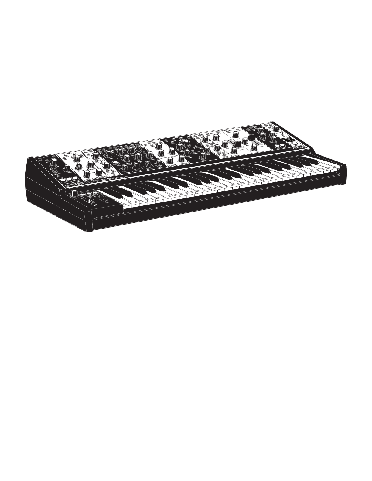
Based on the vintage circuitry of classic Moog synthesizer modules, Matriarch
is a catalyst for creative ideas and a medium for multidimensional expression.
6 7
Page 7
UNPACKING & INSPECTION
Check the contents of the shipping carton. Be careful when unpacking your new Moog Matriarch® so
that nothing is lost or damaged. Moog recommends saving the carton and all packing materials in case
you ever need to ship the instrument for any reason.
Matriarch ships with the following items:
Matriarch Semi-Modular Analog Synthesizer
Power Supply
Owner’s Manual
Patch Cables
Registration Card
1.
2.
3.
4.
5.
What you will need:
A table or surface where you can set your Matriarch. (30lbs / 13.61kg)
A 1/4” instrument cable and amplified speaker, or headphones with a 1/4” plug.
A properly wired AC outlet. (100 Volts to 240 Volts AC; 50/60 Hz)
1.
2.
3.
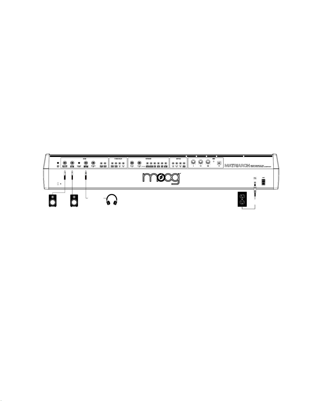
SETUP & CONNECTIONS
Speakers
Headphones
Power
Supply
POWER
Plug the included power adapter into the 12V DC power jack on the back of your Matriarch. Plug the
other end of the included power adapter into an AC outlet. Matriarch uses a universal power supply
that operates with power sources from 100 Volts to 240 Volts AC; 50/60 Hz.
NOTE: Your Matriarch is an analog instrument and should be allowed 10-15 minutes to warm up before use.
In cases where it has been left in a cold car overnight, for example, it may take as long as 25 minutes before
oscillator tuning has stabilized. Do not operate Matriarch in direct sunlight.
AUDIO OUTPUTS
With the Matriarch MAIN VOLUME knob turned all the way down, plug one end of a 1/4” (TS)
instrument cable into the MAIN OUT LEFT (MONO) jack on the rear panel to monitor the instrument
in mono. To monitor the instrument in stereo, connect a second 1/4” (TS) instrument cable to the
MAIN OUT RIGHT jack on the rear panel.
NOTE: The MAIN OUT jacks will work with both TS and TRS 1/4” cables.
Plug the other end(s) into an amplified speaker or mixing console line-level input. Raise the MAIN
VOLUME knob above the 12 O’clock position, and adjust the amplifier or mixer level accordingly.
HEADPHONE OUT
Also on the rear panel is a stereo headphone jack, complete with its own HEADPHONE VOLUME
knob for private listening or monitoring.
NOTE: This headphone jack is unaected by the MAIN VOLUME knob in the Output module on the front panel.
8
Page 8
ABOUT MATRIARCH
Matriarch sits at the pinnacle of the Moog family of semi-modular synthesizers. The patchable architecture
and classic Moog circuits reward open exploration with endless sonic possibilities and unparalleled analog
sound. Matriarch’s four analog VCOs can be split into four notes of paraphony that can be sequenced,
shifted, and stored with the instrument’s intuitive 256 step Sequencer, or stacked in unison to create a
massive four-oscillator mono synth.
With a deep assortment of synthesis modules based on Bob Moog’s original circuit designs, Matriarch
provides a 100% analog signal path spanning a dynamic sonic vocabulary – from overdriven monophonic
bass to gently evolving paraphonic plucks that cycle through waveshapes into a wash of infinite delay
trails. Coupling the power of vintage-designed stereo Ladder Filters, dual Envelope Generators, stereo
Analog Delays, and stereo VCAs, Matriarch delivers a multi-dimensional sound that empowers the sonic
exploration of both space and time.
Although Matriarch uses a semi-modular design that requires absolutely no patching, 90 modular patch
points are easily accessible throughout the panel via the included 3.5mm patch cables. This powerful
electronic instrument is a highly-versatile addition to any stage or studio that can effortlessly transform
from a performance keyboard into a fully modular analog synthesizer at a moment’s notice.
In addition to its standalone function, Matriarch is also an ideal processor of external sound sources and a
powerful keyboard front-end for expanding a DFAM, Mother-32, Grandmother, or Eurorack modular system.
MOD
EXQUISITE EXPRESSION
49 velocity-sensing keys with
aftertouch, glide, and pitch &
mod wheels.
HANDS-ON INTERFACE
Color-coded semi-modular front
panel with single-function knobs,
switches, and buttons.
PATCHABLE PERFORMER
90 modular patch points with
expression pedal connectivity,
external audio input, plus 5-Pin
DIN & USB MIDI.
OSCILLATOR ABUNDANCE
4 analog oscillators with Hard
Sync and FM capabilities.
FLEXIBLE FILTERING
Dual Ladder filters configurable
in series, parallel, or stereo modes.
RHYTHMIC RECALL
Record and playback 12 unique
sequences with up to 256 notes
each, or arpeggiate endlessly
through a random selection of
held notes.
9
MULTIPLE MODULATORS
Dual, voltage-controlled analog
LFOs with selectable waveforms
and patchable routing.
ANALOG EFFECTS
Stereo analog delay with MIDI
sync, ping pong, and tap tempo.
USEFUL UTILITIES
Three bipolar voltage-controlled
attenuators and two 4-jack mults.
VERSATILE VOICING
Perform in mono (1-note), 2-note,
and 4-note paraphonic modes.
Page 9
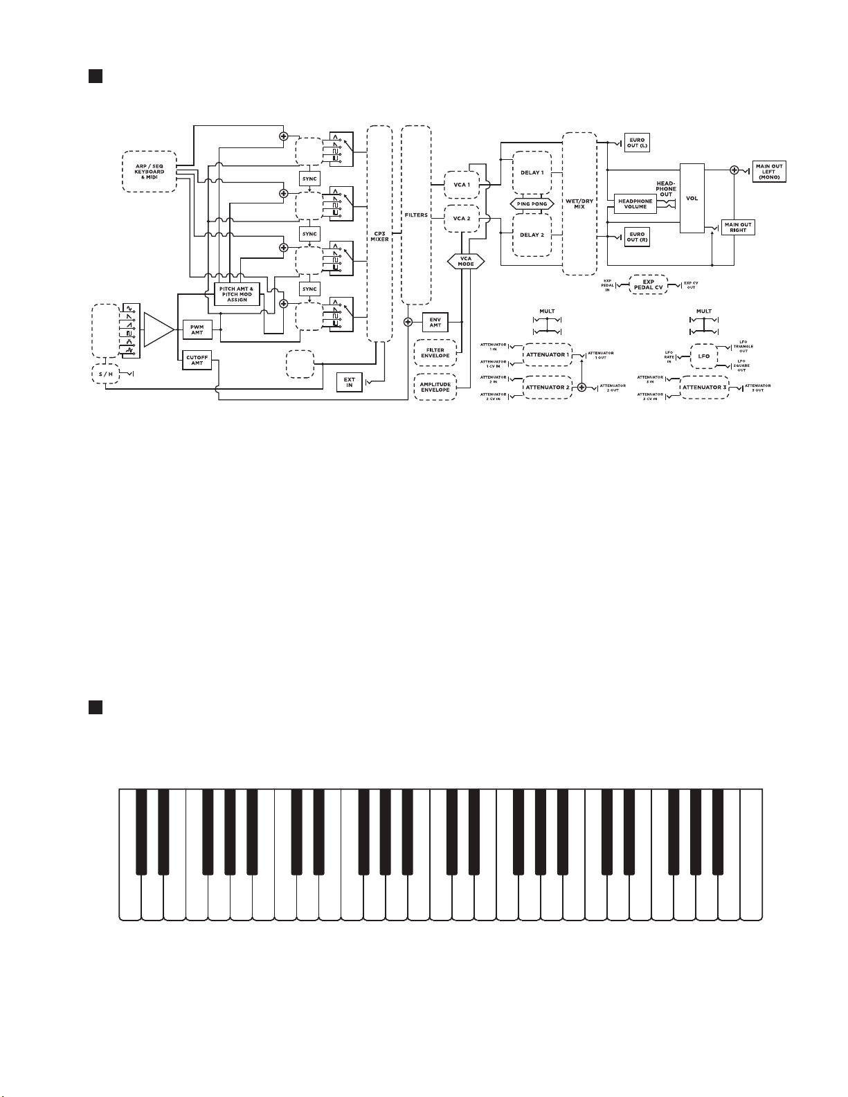
SIGNAL FLOW
PITCH
OSC 1
PWM
PITCH
OSC 2
PWM
PITCH
OSC 3
PWM
PITCH
MOD
OSC
MOD
WHEEL
VCA
REFERENCE: To view the full Signal Flow diagram see Page 70-71.
OSC 4
PWM
NOISE
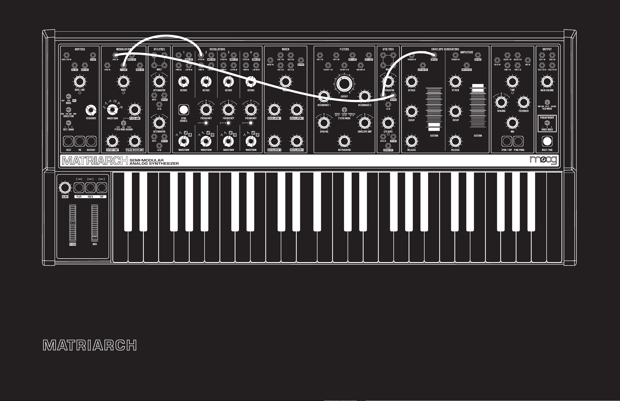
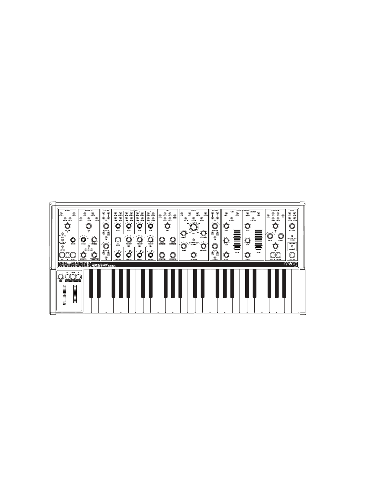
FEATURES & CONTROLS
Matriarch’s panel is comprised largely of single-function knobs, switches, and buttons that are grouped
together by module. Each module is equipped with a set of 3.5mm patch points that can be utilized
to create new audio and control pathways within Matriarch. These patch points can also be used to
establish synchronization and interconnectivity with other Moog synthesizers like Mother-32, DFAM,
and Grandmother, or to create a completely a new instrument through deep integration with a
Eurorack modular system.
NOTE: Additional patch points and connectors are available on Matriarch’s rear panel.
KEYBOARD
Matriarch offers a 49-note Fatar keyboard with velocity and channel aftertouch. There are no hardwired
connections for these signals; they can be easily accessed via rear-panel patch points and MIDI.
NOTE: By using the Mults and Attenuators found in the Utilities modules, multiple parameters can be aected –
in varying amounts – using the Keyboard Pitch, Velocity and Aftertouch control signals.
10
Page 10
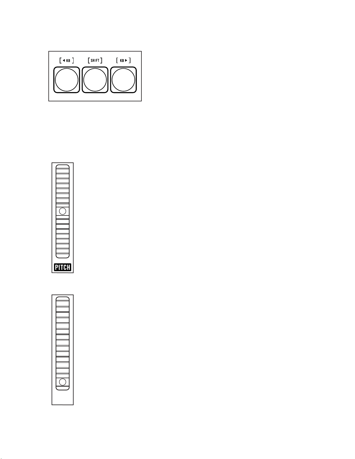
LEFT-HAND CONTROLLER
The Left-Hand Controller (LHC) is home to a number of
performance-enriching controls. The PITCH (Pitch Bend) and
MOD (Modulation) wheels deliver real-time expression, while
the GLIDE knob provides enhanced articulation between
notes. The Left-Hand Controller is also home to the Transport
Buttons for the Arpeggiator and Sequencer, allowing instant
access to these powerful features during performance.
MOD
TRANSPORT BUTTONS
PLAY
The green P L AY button acts as a toggle, either arming or
disarming the Arpeggiator or Sequencer. When this button is
lit, pressing the notes to be arpeggiated, or the starting note
of a sequence, will begin playback. This button will remain lit
when the Sequencer or Arpeggiator is armed.
HOLD
The blue HOLD button acts as a latch for the Arpeggiator and
the Sequencer, where notes played and released remain held
until new notes are played. This button will remain lit as long
as the Hold function is engaged.
TAP
The playback tempo of the Arpeggiator or Sequencer can be
set using a series of successive taps on this yellow TAP button.
Once a Tempo has been entered using the TAP button, it will
remain lit yellow. To exit Tap Tempo, simply press and hold the
TAP button until its light goes out.
TIP: As long as the TAP button is lit yellow (indicating a tempo
has been entered using this method), turning the RATE knob in
the ARP / SEQ module will select clock divisions of this tempo.
NOTE: More specific information regarding these buttons can be
found in the ARP / SEQ chapter of this manual located on Page 49.
11
Page 11
LEFT-HAND CONTROLLER (Continued)
OCTAVE TRANSPOSE
The Transport Buttons can also be used to shift the pitch of the
keyboard up or down in one-octave increments. This allows
the range of the keyboard to be extended without changing
the settings of individual oscillators. To transpose the keyboard
by octave units, simply press and hold the [SHIFT] button,
and then press the [<KB] button (down one octave) or [KB>]
button (up one octave). The transpose range is up or down
two octaves.
NOTE: Press the HOLD, PLAY, and TAP buttons at the same time
to reset Matriarch to its default octave. Press and hold these same
three buttons for one second to utilize the MIDI Panic function
and silence any stuck notes.
PITCH
The PITCH wheel (Pitch Bend) provides an intuitive method for quickly bending the
pitch of the oscillators up or down during live performance.
NOTE: The PITCH wheel is spring-loaded and will return to center position as soon as it is released.
MOD
MOD
The MOD wheel (Modulation) provides an expressive way to introduce and control
modulation while performing. At minimum position, no modulation is applied. As the
MOD wheel’s position is raised, more modulation is introduced. At its uppermost
position, the amount of modulation is equal to the maximum values set using the
PITCH AMT (Oscillator Pitch), CUTOFF AMT (Filter Cutoff Frequency), and PULSE
WIDTH AMT (Pulse Width Modulation [PWM]) knobs in the Modulation module.
NOTE: Unlike the PITCH wheel, the MOD wheel is not spring-loaded, and will remain in
position until it is moved again.
TIP: You can patch from the MOD WHL OUT jack on the Matriarch rear panel to any available
destination for a more expressive and expansive performance.
12
Page 12
LEFT-HAND CONTROLLER (Continued)
GLIDE
Glide produces a smooth, continuous change in pitch when transitioning
from one note to the next. The GLIDE knob sets the amount of time needed
to complete this transition. When the GLIDE knob is set to minimum, there is
no Glide effect. Raising the value of the GLIDE knob will increase the Glide
time between notes from zero to a maximum value of roughly ten seconds.
TIP: Legato Glide only produces the Glide eect when a new note is played while the
previous note is still held down on the keyboard. To turn Legato Glide On, continue
to press the [SHIFT] button while turning the GLIDE knob to the right. To turn Legato
Glide O, continue to press the [SHIFT] button while turning the GLIDE knob to the
left. The Default setting for Legato Glide is O.
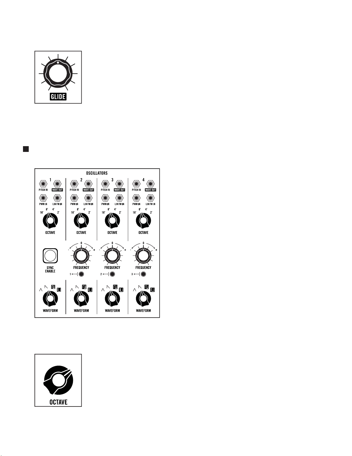
OSCILLATORS
Matriarch’s analog sound begins with four
voltage-controlled oscillators (VCOs) of
nearly identical design. Each oscillator provides
individual control of the Octave and Waveform
settings, while Oscillators 2, 3, and 4 also feature
a FREQUENCY knob used for detuning from
Oscillator 1.
Oscillators can be tuned in unison or set to
differing intervals, octaves, and waveforms
to create a vast expanse of monophonic and
paraphonic sounds.
Oscillators 2, 3, and 4 can also be Hard Sync’d to
the previous oscillator using the dedicated SYNC
buttons – Oscillator 2 can be sync’d to Oscillator 1,
Oscillator 3 to Oscillator 2, and Oscillator 4 to
Oscillator 3.
NOTE: There is a FINE TUNE knob located on
Matriarch’s rear panel for adjusting the overall
tuning of the instrument.
MODULE PROVENANCE: Matriarch’s Oscillators are based on those found in the Minimoog Voyager and are
descendants of the classic Moog 921 Oscillator design.
OCTAVE
This four-position switch is used to select the fundamental octave setting
for each oscillator. The choices are 16’, 8’, 4’ and 2’.
NOTE: These octave numbers originated as lengths (or footages) in the days
of pipe organs.
16’
8’ 4’
2’
13
Page 13
OSCILLATORS (Continued)
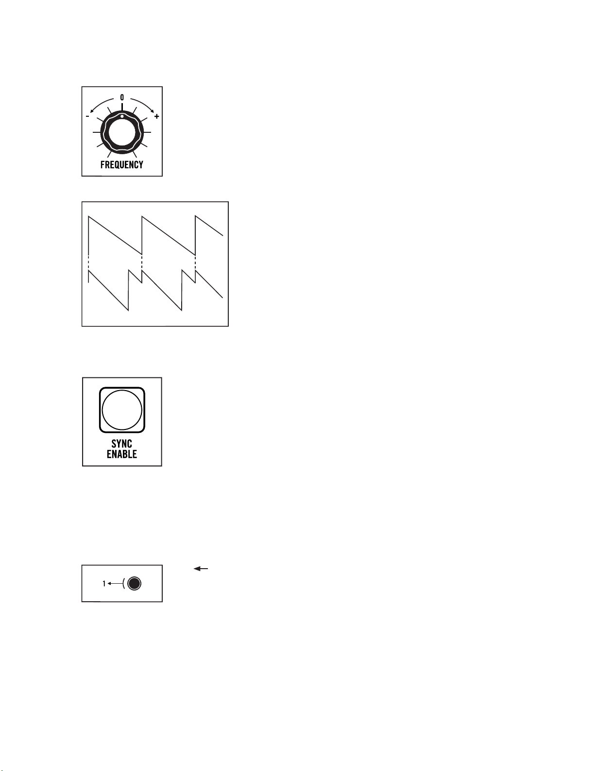
FREQUENCY (Oscillators 2, 3, & 4)
The FREQUENCY knob detunes each oscillator from the pitch of Oscillator 1 over
a range of +/- 7 semitones (or a musical 5th). The center position (12 O’clock)
tunes the oscillator in unison with Oscillator 1. Increasing the value (+) raises
the pitch, while decreasing the value (–) lowers the pitch.
NOTE: The range of the FREQUENCY knobs can be specified in the Global Settings.
OSCILLATOR
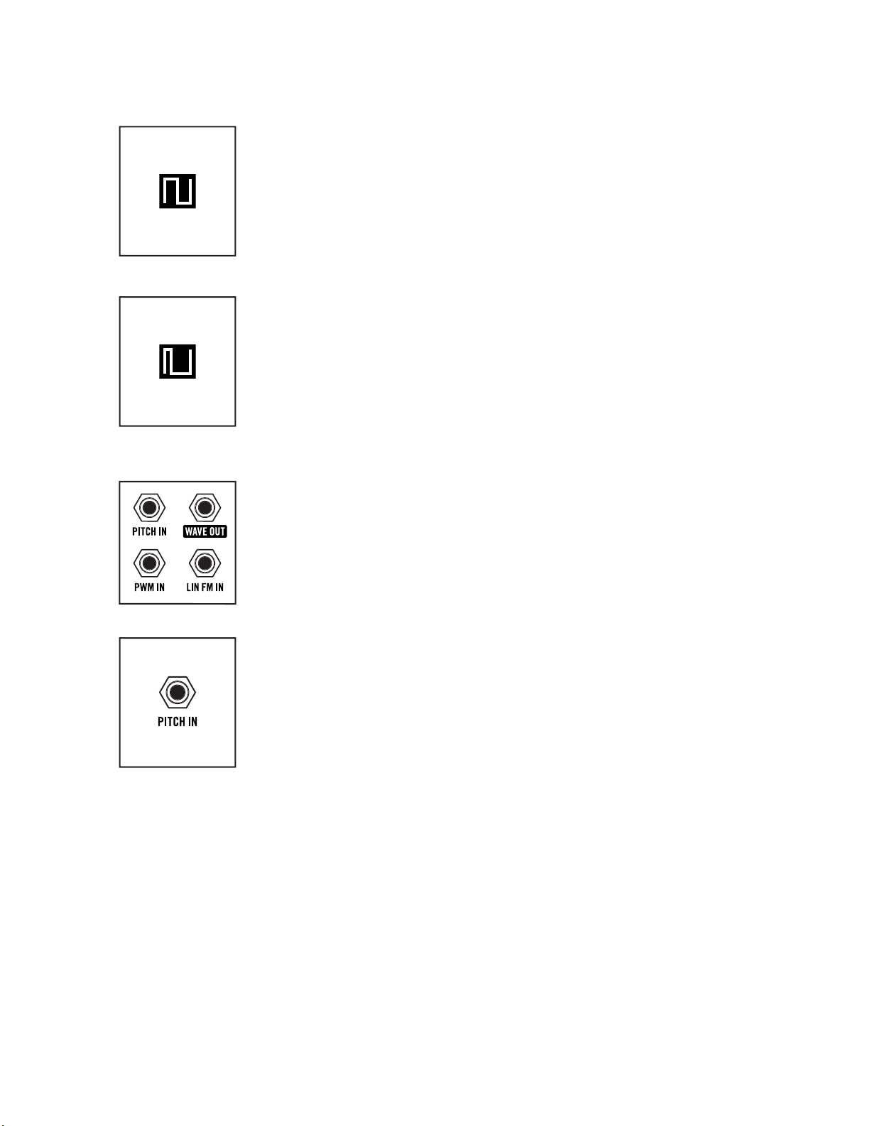
HARD SYNC’D OSCILLATOR
SYNC ENABLE (Main)
Pressing the main red SYNC ENABLE button enables the Sync functions of
Oscillator 2, Oscillator 3, and Oscillator 4. The button will remain lit as long as
the Sync function is On. Press the red SYNC ENABLE button a second time to
turn the Sync function Off.
NOTE: When the frequency of the sync’d oscillator is set below that of the oscillator
it is sync’d to, the sync’d oscillator will not be able to complete a full cycle before it
is forced to reset, resulting in little or no sound.
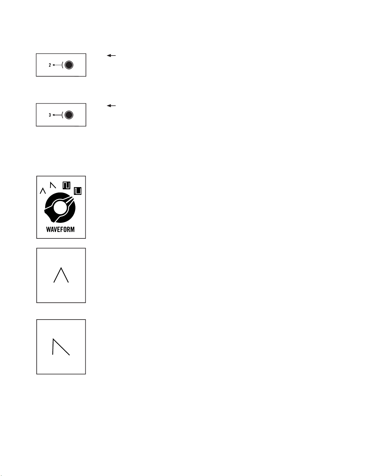
UNDERSTANDING OSCILLATOR SYNC
When two oscillators are sync’d, the first oscillator behaves
normally, while the phase of the second, or sync’d oscillator, is
forced to reset its cycle to match each new cycle of the first
oscillator. This synchronization causes the waveform of
the sync’d oscillator to take on a more complex wave shape
as it works to stay aligned with the first oscillator. Sync is useful
for creating sharp, metallic, and flange-like sounds, while also
ensuring that the pitch of the sync’d oscillator stays locked
to the pitch of the first oscillator.
TIP: Applying modulation to the pitch of a sync’d oscillator is a great
way to enhance the sound of the Sync eect.
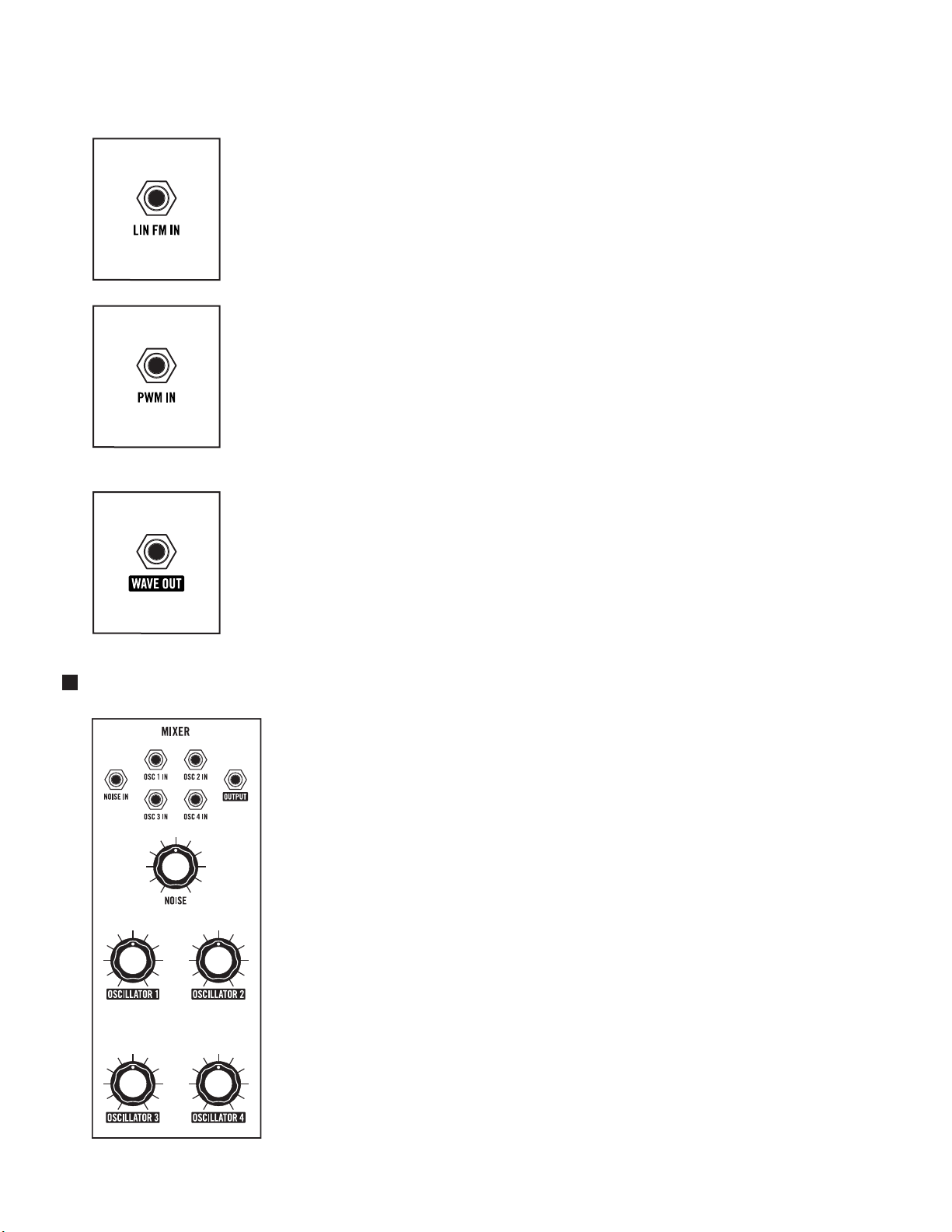
INDIVIDUAL OSCILLATOR SYNC (Oscillators 2, 3, & 4)
Oscillators 2, 3, and 4 are each equipped with a dedicated button that allows
it to be sync’d to the previous oscillator.
1 2 SYNC
Pressing this button (On/lit red) will cause Oscillator 2 to become sync’d to
Oscillator 1. In this case, changing the Frequency of Oscillator 2 will vary the
degree of the Sync effect and its associated harmonic content. The range of
the FREQUENCY knob is also greatly increased while the oscillator is sync’d.
14
Page 14
OSCILLATORS (Continued)
2 3 SYNC
Pressing this button (On/lit red) will cause Oscillator 3 to become sync’d to
Oscillator 2. In this case, changing the Frequency of Oscillator 3 will vary the
degree of the Sync effect and its associated harmonic content. The range of
the FREQUENCY knob is also greatly increased while the oscillator is sync’d.
3 4 SYNC
Pressing this button (On/lit red) will cause Oscillator 4 to become sync’d to
Oscillator 3. In this case, changing the Frequency of Oscillator 4 will vary the
degree of the Sync effect and its associated harmonic content. The range of
the FREQUENCY knob is also greatly increased while the oscillator is sync’d.
NOTE: Remember, the main red SYNC button must be On (lit) for the individual
Oscillator Sync functions to work.
WAVEFORM (Triangle, Sawtooth, Square, Pulse)
Each waveform has unique harmonic content that is based on the number and
strength of the harmonic overtones that it contains. These overtones are what
impart a particular timbre, or character, to the sound of each oscillator. This
four-position knob is used to select the oscillator’s waveform. The choices are
Triangle, Sawtooth, Square, and Narrow Pulse.
TRIANGLE
The Triangle wave has an extremely strong fundamental, and contains only
odd-numbered harmonics at very low levels. This makes the Triangle wave an
ideal choice for creating soft, flute-like sounds that have a relatively pure tone
with little overtone activity.
TIP: Try mixing a Triangle wave from one oscillator with a more complex wave from
another to emphasize one particular harmonic without adding unwanted overtones.
SAW TOOTH
The Sawtooth wave is the most harmonically dense of the four waveform
options, containing all of the natural harmonics in relatively strong levels.
In addition to creating thick, brassy sounds, the Sawtooth wave lends itself
to powerful lead and bass sounds as well.
PULSE WAVES (Square & Narrow Pulse)
A Pulse wave contains only odd-numbered harmonics. Think of it as a switch that is being turned off
and on hundreds or thousands of times per second. Pulse width, or duty cycle, is the percentage of
time that the wave is “on.” Every pulse width has its own unique harmonic structure, making a variety
of basic timbres possible.
15
Page 15
OSCILLATORS (Continued)
SQUARE
A Square wave is simply a Pulse wave with a 50% duty cycle, meaning that in
a single cycle, it is on half of the time and off half of the time. If the frequency
is 440 Hz, it turns on and off 440 times every second. Square waves have a
hollow sound and provide a rich starting point for clarinet and bass sounds.
NARROW PULSE
As a Pulse wave continues to grow narrower, the resulting timbre takes
on a more reedy, or nasal tone and is used to make oboe and even classic
“clav” sounds.
TIP: Varying the duty cycle of the Pulse wave can result in a wide variety of lush
or chorus-like sounds. With at least one oscillator set to produce a Pulse wave, try
experimenting with the PULSE WIDTH AMT knob in the Modulation module and
listen to how modulating this waveform aects the sound.
OSCILLATOR PATCH POINTS
Each Matriarch oscillator is equipped with versatile patch points, allowing for a
variety of modulation possibilities, including Linear FM (Frequency Modulation)
and PWM (Pulse Width Modulation).
NOTE: The patch points for each oscillator are identical.
PITCH IN (Exponential Frequency Modulation)
A control signal connected to this input will modulate the Pitch (Frequency)
of a patched oscillator and all subsequent oscillators, unless a subsequent
oscillator is also receiving a modulation signal via its own PITCH IN jack. This
input voltage is added to the voltage from the note played on the keyboard.
NOTE: Connecting a modulation source to the PITCH input on Oscillator 1 will aect
the Pitch of Oscillators 1, 2, 3, and 4. Connecting an additional modulation source
to the PITCH input of Oscillator 2 will aect the Pitch of Oscillators 2, 3 and 4 , and
will prevent the modulation signal arriving at the Oscillator 1 PITCH input jack from
modulating these oscillators.
TIP: By connecting a modulation source to the Oscillator 1 PITCH IN jack, and a “dead
patch” to the Oscillator 2 PITCH IN jack, only Oscillator 1 will receive the modulation
signal. A dead patch is a cable connected to a patch point with no connection on the
opposite end, used to interrupt normalized signal paths.
CV INPUT: -5V to +5V Control Voltage (1V/Oct)
16
Page 16
OSCILLATORS (Continued)
LIN FM IN (Linear Frequency Modulation)
Connecting an audio signal or high-frequency control signal to this input
introduces Linear Frequency Modulation (FM) to a patched oscillator, which
can be useful in creating brash, metallic, or bell-like tones.
CV INPUT: -5V to +5V Control Voltage (AC coupled)
PWM IN
A control signal connected to this input will modulate the pulse width of the
Square or Narrow Pulse waveform selected by a patched oscillator. Pulse Width
Modulation (PWM) varies the duty cycle, or pulse width of a wave, and thereby
changes its harmonic content. Among other things, PWM is often used to mimic
the sound of ensemble strings and to thicken bass sounds.
CV INPUT: -5V to +5V
WAVE OUT
The audio signal available at this output is determined by the settings of the
OCTAVE, FREQUENCY, SYNC and WAVEFO R M knobs of a patched oscillator.
MIXER
CV / AUDIO OUTPUT: 10V peak-to-peak
The Mixer is where all of the sound sources within Matriarch are blended
together before being passed on to the Filter. Patch points in the Mixer
allow each hardwired source (Oscillators 1 – 4 and Noise) to be replaced
with an external audio signal. There is also a line-level Instrument Input on
Matriarch’s rear panel that feeds directly to the Mixer.
MODULE PROVENANCE: Matriarch’s Mixer is based on the classic
Moog CP3 module.
17
Page 17
MIXER (Continued)
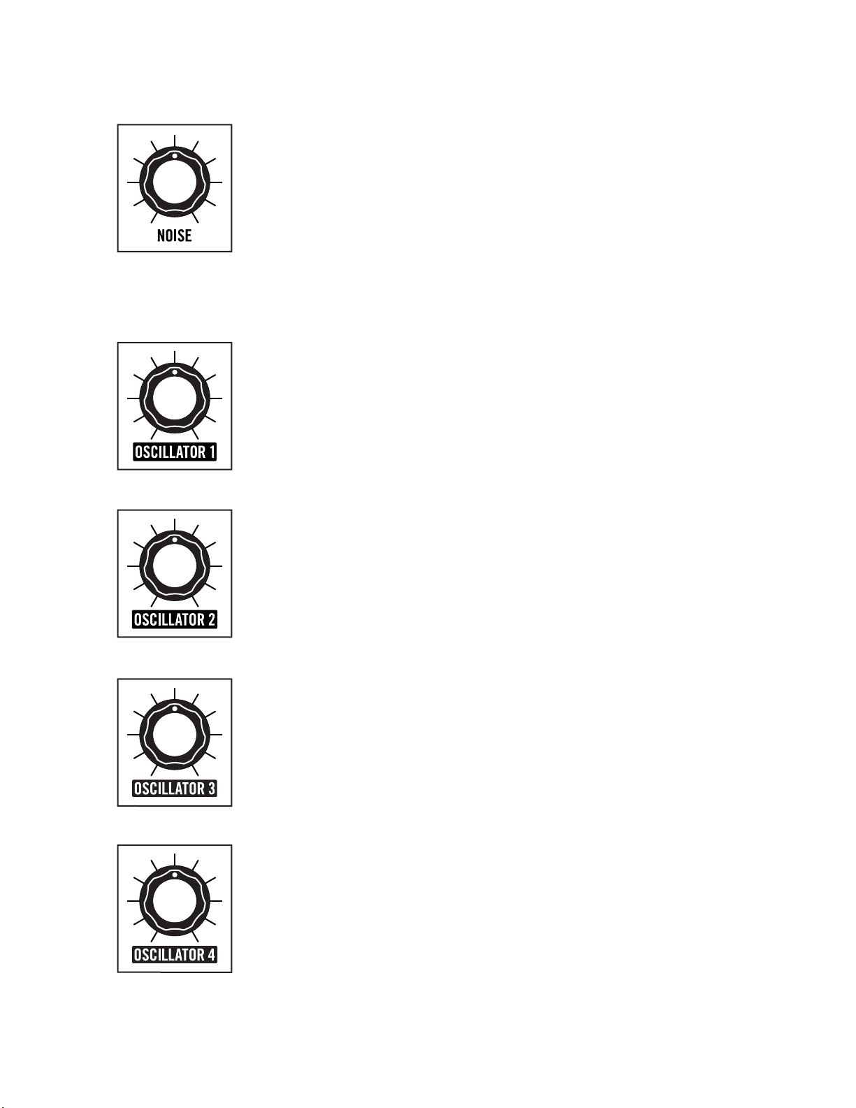
NOISE
Matriarch features a built-in White Noise generator. Noise is an unpitched
sound source that can be a useful tool for creating powerful percussion sounds,
or for adding a gentle breath to synthesized wind instruments such as flutes.
The NOISE knob sets the level of the White Noise generator as it enters the
Mixer. Settings above 11 O’clock will impart gentle distortion, while higher
settings will result in more overdriven sounds.
NOTE: A High Pass Filter (HPF) can be applied to the noise signal using the Global
Settings on page 63, allowing the color (or harmonic strength per frequency band) to
be adjusted.
OSCILLATOR 1
The OSCILLATOR 1 knob sets the level of Oscillator 1 as it enters the Mixer.
Settings above 11 O’clock will impart gentle distortion, while higher settings
will result in more overdriven tones.
OSCILLATOR 2
The OSCILLATOR 2 knob sets the level of Oscillator 2 as it enters the Mixer.
Settings above 11 O’clock will impart gentle distortion, while higher settings
will result in more overdriven tones.
OSCILLATOR 3
The OSCILLATOR 3 knob sets the level of Oscillator 3 as it enters the Mixer.
Settings above 11 O’clock will impart gentle distortion, while higher settings
will result in more overdriven tones.
OSCILLATOR 4
The OSCILLATOR 4 knob sets the level of Oscillator 4 as it enters the Mixer.
Settings above 11 O’clock will impart gentle distortion, while higher settings
will result in more overdriven tones.
18
Page 18
MIXER (Continued)
MIXER PATCH POINTS
These Mixer module patch points provide a convenient
way to replace any or all of the internal sound sources
entering the Mixer with an external sound source, such as
a Eurorack oscillator or other electronic music devices.
TIP: Matriarch’s Mixer is DC coupled, which means it can
also be used to sum multiple control voltages. Combining
audio signals with control signals will yield results that can
be unique, bizarre, or completely undesirable.
PERFORMANCE NOTE: Mix gates are located on Oscillator channels 1-4. When in 2-Note or 4-Note Paraphonic
mode, external sources will be dynamically muted just as the onboard oscillators would.
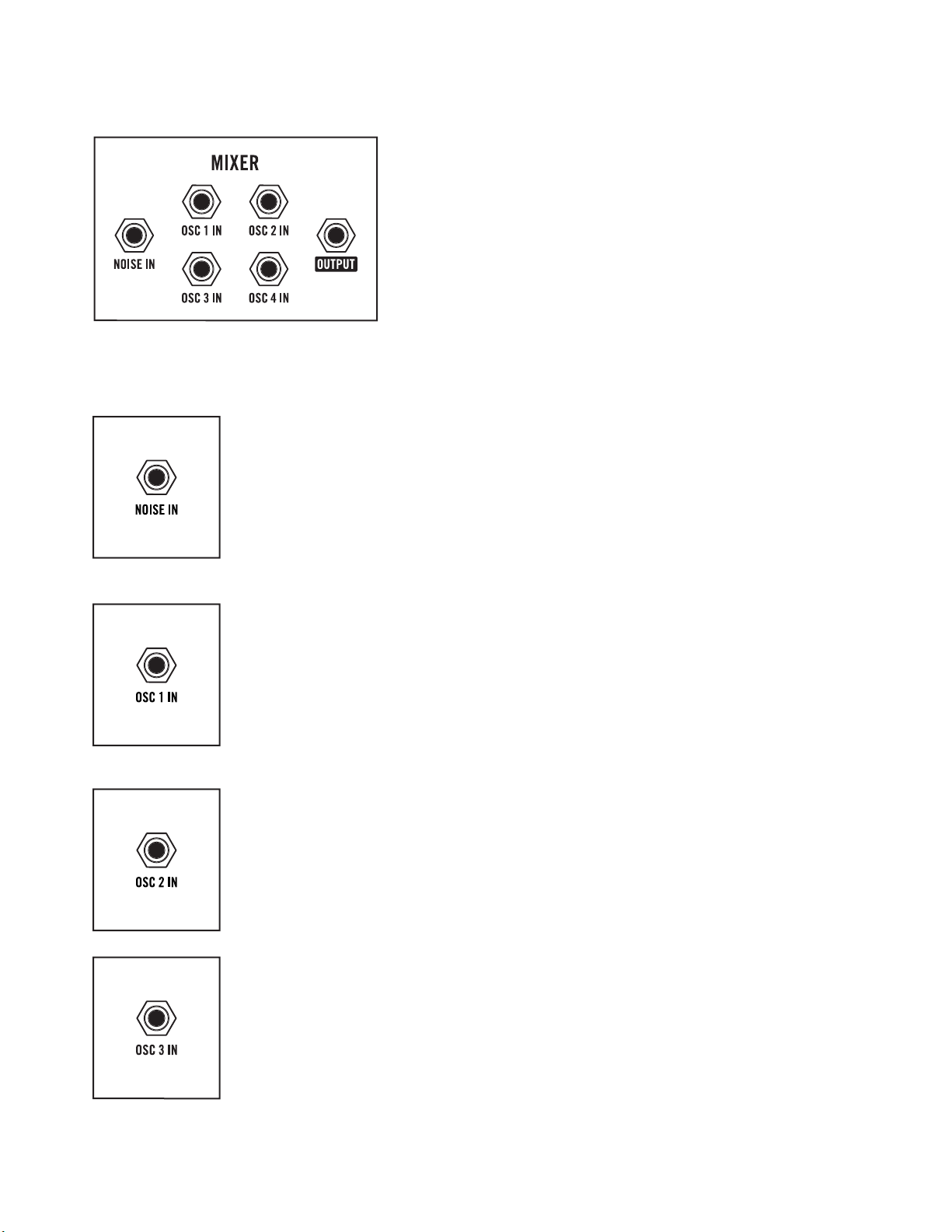
NOISE IN
When an external audio source is patched to this input, the Noise generator
will be removed from the signal path, and the NOISE knob will control the
level of the new source.
AUDIO INPUT: -5V to +5V (10V peak-to-peak)
OSC 1 IN
When an external audio source is patched to this input, Oscillator 1 will be
removed from the signal path, and the OSCILLATOR 1 knob will control the
level of the new source.
AUDIO INPUT: -5V to +5V (10V peak-to-peak)
OSC 2 IN
When an external audio source is patched to this input, Oscillator 2 will be
removed from the signal path, and the OSCILLATOR 2 knob will control the
level of the new source.
AUDIO INPUT: -5V to +5V (10V peak-to-peak)
OSC 3 IN
When an external audio source is patched to this input, Oscillator 3 will be
removed from the signal path, and the OSCILLATOR 3 knob will control the
level of the new source.
AUDIO INPUT: -5V to +5V (10V peak-to-peak)
19
Page 19
MIXER (Continued)
FI LTERS
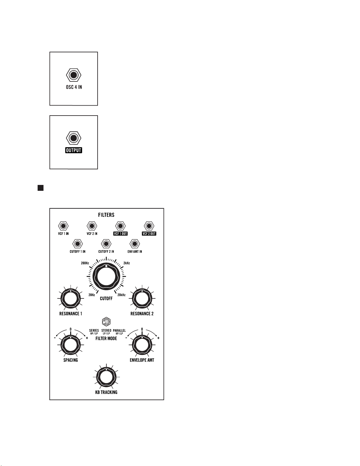
OSC 4 IN
When an external audio source is patched to this input, Oscillator 4 will be
removed from the signal path, and the OSCILLATOR 4 knob will control the
level of the new source.
AUDIO INPUT: -5V to +5V (10V peak-to-peak)
OUTPUT
The combined signal of all audio sources connected to the Mixer is available
at this output.
AUDIO OUTPUT: 10V peak-to-peak
Filters are paramount in shaping the tone of your
sound. While an oscillator’s waveform determines the
harmonic content of a raw wave, it is the filter that
allows that harmonic content to be shaped, sculpted,
and modulated over time to create something truly
unique.
Matriarch’s filters operate in one of three selectable
modes; Series, Parallel, or Stereo. Depending on the
current setting of the FILTER MODE switch, VCF 1 has
the ability to operate in either High Pass or Low Pass
mode, while VCF 2 maintains its Low Pass operation
at all times.
NOTE: A stereo signal path is available from the filters onward.
MODULE PROVENANCE: Matriarch’s filters are based on the
classic Moog 904A module.
20
Page 20
FI LTERS (Continued)
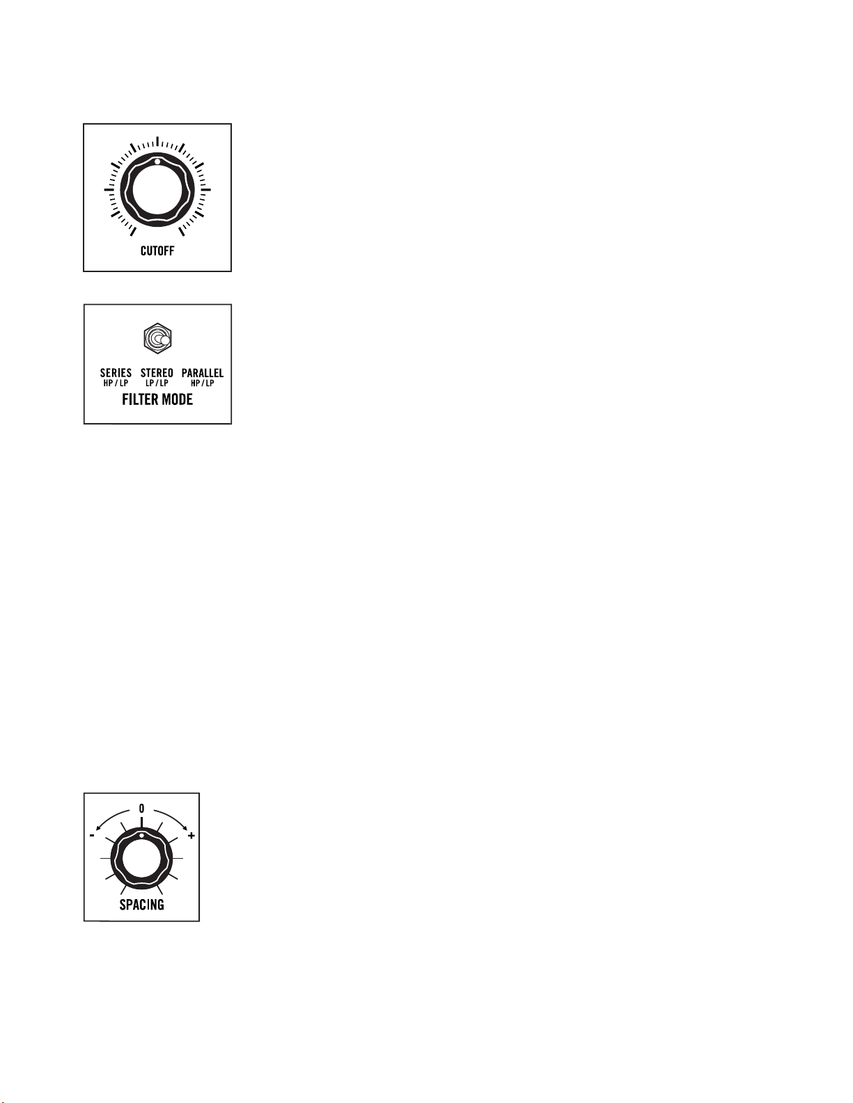
200Hz 2kHz
20Hz 20kHz
CUTOFF
Matriarch’s CUTOFF knob specifies the Filter Cutoff frequency for both
VCF 1 and VCF 2 in a linked fashion. The SPACING knob is used to offset
the frequency of VCF 1, above or below the Cutoff Frequency of VCF 2.
FILTER MODE
This three-position switch defines how VCF 1 and VCF 2 are configured,
and how they will interact with each other.
HP / LP SERIES
In this mode, VCF 1 is configured as a High Pass filter and VCF 2 is
configured as Low Pass filter. Signal passes from the Mixer module into
VCF 1 (High Pass), and then is routed into VCF 2 (Low Pass). The mono
output signal from VCF 2 feeds both VCA 1 and VCA 2.
NOTE: This is the foundation for creating a Band Pass filter.
LP / LP STEREO
In this mode, VCF 1 and VCF 2 function independently as Low Pass filters.
Both receive the same signal from the Mixer module. VCF 1 is routed to
VCA 1, and VCF 2 is routed to VCA 2. This creates a true-stereo signal path
to the outputs.
HP / LP PARALLEL
In this mode, VCF 1 is configured as a High Pass filter and VCF 2 is
configured as a Low Pass filter. Both receive the same signal from the
Mixer module, and their outputs are combined into a monaural signal
that feeds both VCA 1 and VCA 2.
NOTE: This is the foundation for creating a Notch filter.
REFERENCE: To see Filter Mode Signal Flow diagrams see Page 72-73.
SPACING
Both VCF 1 and VCF 2 share the same Cutoff frequency value as
determined by the CUTOFF knob. This SPACING knob specifies an offset
in the value of the Cutoff frequency of VCF 1 in relation to the Cutoff
frequency of VCF 2. This knob is bipolar; so turning this knob clockwise
from center (+) increases the Cutoff frequency of VCF 1 to a value above
that of VCF 2. Turning this knob counterclockwise (-) decreases the Cutoff
frequency of VCF 1 to a value below that of VCF 2. In the center position,
the Cutoff frequency of VCF 1 is equal to the Cutoff frequency of VCF 2.
NOTE: The SPACING knob only aects the Cuto Frequency of VCF 1.
21
Page 21
FI LTERS (Continued)
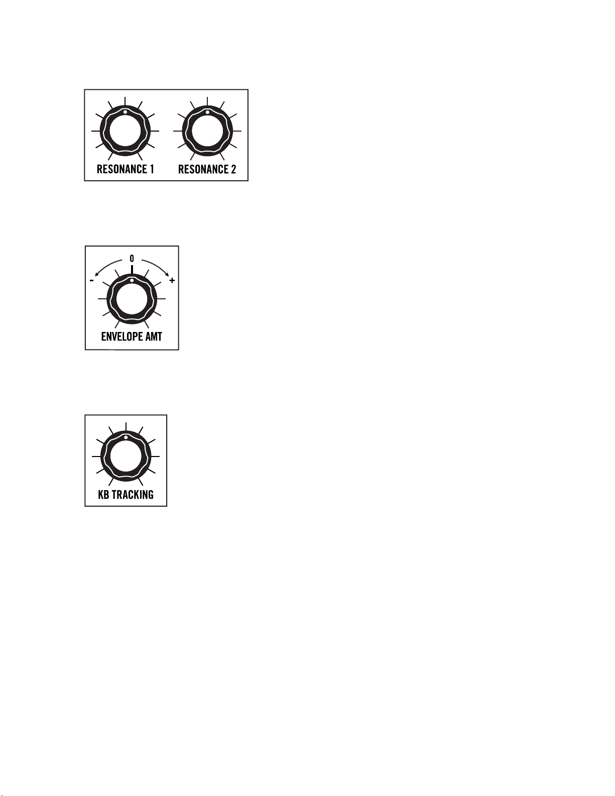
RESONANCE 1 & 2
Resonance channels a portion of the Filter’s output back
to the input of the Filter, creating an emphasis peak at the
Filter’s Cutoff frequency. This is useful for adding focus,
funkiness, or “sci-fi laser blasts” to a sound.
The RESONANCE 1 knob sets the amount of Resonance
being applied to VCF 1, while the RESONANCE 2 knob sets
the amount of Resonance being applied to VCF 2.
NOTE: A RESONANCE knob setting of around 3 O’clock or more will cause the filter to self-oscillate.
ENVELOPE AMT (Envelope Amount)
The ENVELOPE AMT knob determines how much of the control signal created
by the Filter Envelope will be applied to the Filter’s Cutoff frequency over
time. This knob is bipolar, so turning the ENVELOPE AMT knob clockwise from
center will raise the Filter’s Cutoff frequency from the CUTOFF knob’s current
setting. Turning it counterclockwise from center will lower the Filter’s Cutoff
frequency from the CUTOFF knob’s current setting.
NOTE: Negative (or inverse) modulation simply flips the shape of the Filter Envelope
generator. Instead of the Attack parameter raising the Cuto frequency over time,
the Attack parameter will lower the Cuto frequency by the same amount, in the
same period of time.
KB TRACKING (Keyboard Tracking)
Keyboard Tracking allows the note being played on the keyboard itself to be
used as a modulation source for the Filter’s Cutoff frequency. Higher notes on
the keyboard may be perceived as being brighter than lower notes – especially
when the filter is in the Low Pass mode.
When the KB TRACKING knob is set to its maximum value (fully clockwise),
the Filter will track the keyboard using the same 1 volt/octave scheme as the
oscillators. At its minimum value (fully counterclockwise), the KB TRACKING
knob will have no effect.
TIP: Setting the RESONANCE and KB TRACKING knobs to maximum allows the
keyboard to play the Filter(s) similarly to an oscillator.
22
Page 22
FI LTERS (Continued)
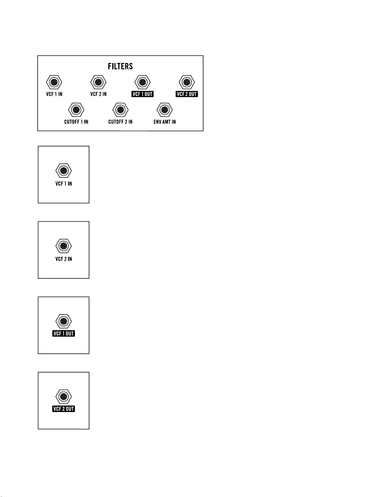
FILTER PATCH POINTS
These Filter module patch points
provide a convenient way to
independently modulate the Cutoff
frequency of VCF 1 and/or VCF 2,
and to modulate the value of the
ENVELOPE AMT knob. In addition,
audio inputs and outputs allow each
filter to be used as a stand-alone
processor for filtering any internal or
external sound source.
VCF 1 IN
The input to VCF 1 is connected to the output of the Mixer module. Patching
an audio signal to this input overrides the Mixer signal, allowing any audio
source to be processed by VCF 1.
NOTE: The path and mode of VCF 1 are determined by the FILTER MODE switch.
AUDIO INPUT: -5V to +5V
VCF 2 IN
The input of VCF 2 is connected to the output of the Mixer or VCF 1, depending
on the position of the FILTER MODE switch. Patching an audio signal to this
input overrides this signal, allowing any audio source to be processed
by VCF 2 using the filter’s current settings.
AUDIO INPUT: -5V to +5V
VCF 1 OUT
The audio output of VCF 1 is available via this jack, allowing it to be sent to any
input on Matriarch itself, or to an external electronic music device.
AUDIO OUTPUT: 10V peak-to-peak
NOTE: VCF 1 can be used as a stand-alone audio processor.
VCF 2 OUT
The audio output of VCF 2 is available via this jack, allowing it to be sent to any
input on Matriarch itself, or to an external electronic music device.
AUDIO OUTPUT: 10V peak-to-peak
NOTE: VCF 2 can be used as a stand-alone audio processor.
23
Page 23
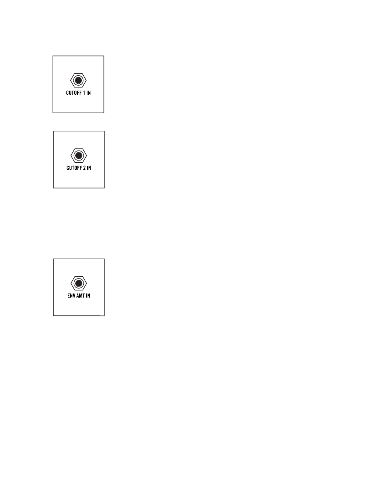
FI LTERS (Continued)
CUTOFF 1 IN
A control signal connected here will modulate the Cutoff frequency of
VCF 1. This is based on the current CUTOFF, SPACING, ENVELOPE AMT,
and KB TRACKING knob settings.
CV INPUT: -5V to +5V
CUTOFF 2 IN
A control signal connected here will modulate the Cutoff frequency of VCF 2.
This is based on the current CUTOFF, ENVELOPE AMT, and KB TRACKING
knob settings.
CV INPUT: -5V to +5V
NOTE: A control signal arriving at the CUTOFF 1 IN jack is normalled to the CUTOFF 2 IN
jack and will aect the Cuto frequency of both VCF 1 and VCF 2. A control signal
connected to the CUTOFF 2 IN jack will aect only the Cuto frequency of VCF 2.
TIP: Connecting a modulation source to the CUTOFF 1 IN jack, and a “dead patch” to
the CUTOFF 2 IN jack will prevent the modulation signal from reaching VCF 2. A dead
patch is a cable connected to a patch point with no connection on the opposite end,
used to interrupt normalized signal paths.
ENV AMT IN
A control signal connected here will modulate the value of the ENVELOPE
AMT knob, thereby changing how much influence the Filter Envelope has
over the Filter Cutoff frequency.
CV INPUT: -5V to +5V
24
Page 24
amplitude
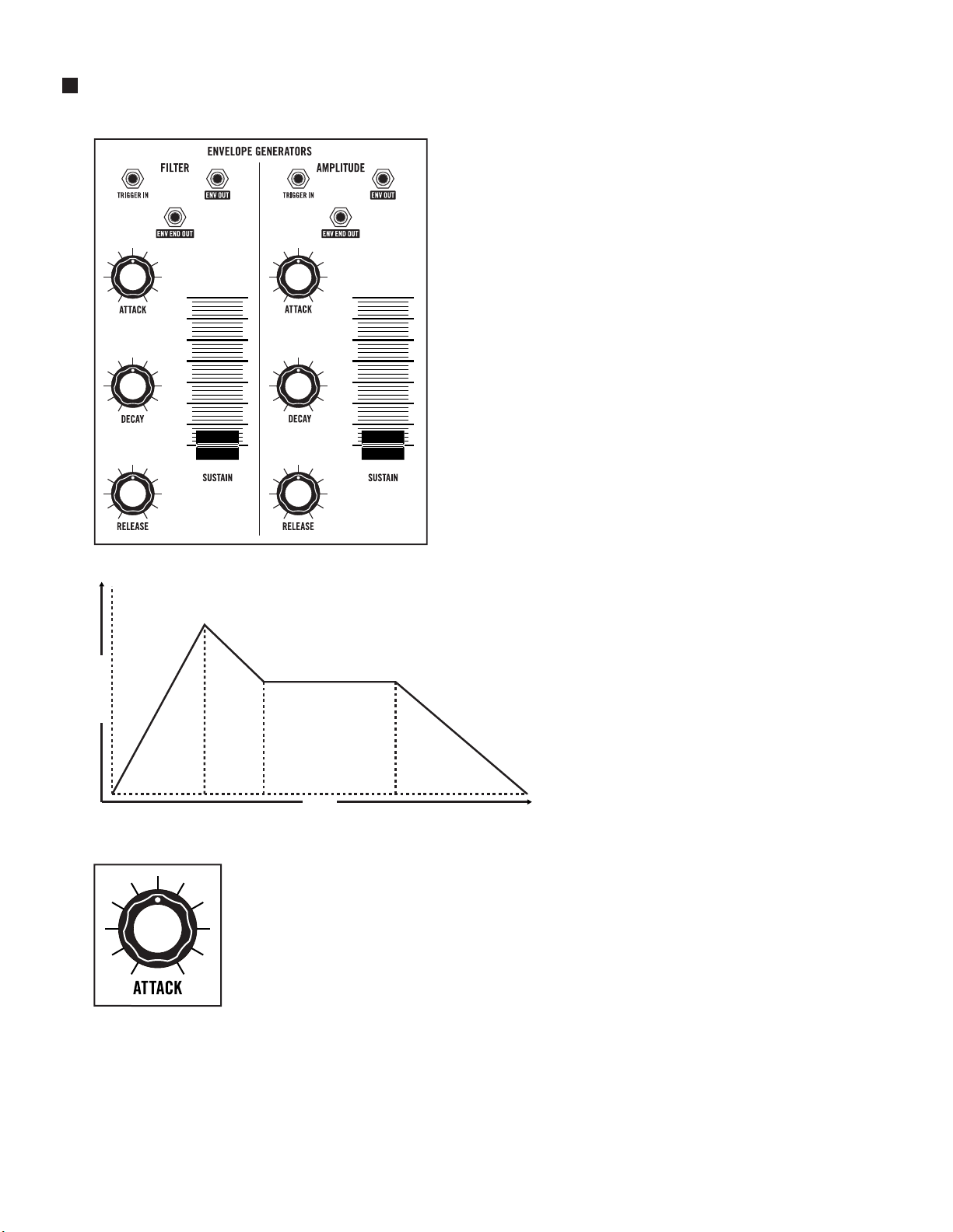
ENVELOPE GENERATORS (ADSR)
Sounds change over time. How they change
over time is part of what makes each one unique.
Some sounds begin abruptly, like the strike of a
drum. Some sounds end just as quickly, and some
linger like a held chord on a piano. We call this
the envelope of a sound. Matriarch uses a pair of
identical Envelope Generators to create control
voltages that also change over time. This type of
control voltage can be applied to the amplitude
of the sound, changing its volume over time. This
same type of control voltage can also be used to
affect the Cutoff frequency of the Filter over time,
creating changes in timbre, or tone.
NOTE: In a semi-modular synthesizer such as Matriarch,
an Envelope Generator can be patched to modulate any
controllable parameter over time.
MODULE PROVENANCE: Matriarch’s Envelope
Generators are based on the classic Moog 911 module.
attack
Regardless of how the Envelope
is applied, there are four main
stages: Attack time, Decay time,
Sustain level, and Release time.
These controls are identical for
both Envelope Generators.
decay
sustain
release
Of these four stages, three relate
to time, and are controlled by
rotary knobs. Only the Sustain
stage relates to level; it is
time
controlled using a slider.
ATTACK
The ATTAC K knob determines the amount of time required for the control
signal to rise from zero to its maximum level once a key is pressed. The ATTACK
knob has a range from 2 milliseconds to 10 seconds. Fast attacks are useful for
creating plucked sounds, while slow attacks are more useful for creating bowed
string sounds and swells. Brass swells will often have a faster Amplitude Attack
and a slower Filter Attack.
25
Page 25

ENVELOPE GENERATORS (ADSR) (Continued)
DECAY
The DECAY knob determines the amount of time required for the control signal
to fall from the maximum level achieved by the Attack stage to the Sustain
level as the key is held. The DECAY knob has a range from 2 milliseconds to 10
seconds. Fast decay times are useful for creating articulated lead notes, while
longer decay times allow a note to fade slowly into the Sustain level.
SUSTAIN
While the Attack, Decay, and Release parameters deal with time, the Sustain
parameter controls level. Once the Attack and Decay stages are complete,
the control signal will remain at the level set by the SUSTAI N slider, keeping
the Amplitude and/or Filter at a steady level for as long as a key is held.
RELEASE
The RELEASE knob determines the amount of time required for the control
signal to fall from its current level to zero once a key is released. The RELEASE
knob has a range from 2 milliseconds to 10 seconds. Shorter settings are good
for classic funk basses that end abruptly, while longer settings are good for
creating smooth musical tails that ring out over time.
26
Page 26

ENVELOPE GENERATORS (ADSR) (Continued)
FILTER ENVELOPE GENERATOR
ENV OUT (Filter EG)
This output provides a control-voltage signal created by the current Filter
Envelope Generator panel settings.
OUTPUT: 0V to +8V
NOTE: When the VCA MODE switch is set to SPLIT, the Filter Envelope Generator
control signal also controls the level of VCA 1 (Left output).
ENVELOPE GENERATOR
PATCH POINTS
These patch points allow each
Envelope Generator to be
triggered from a source other
than the Matriarch keyboard and
can be used to modulate any
patchable parameter internal to
or external of Matriarch.
TIP: An inverted EG signal (-ENV) can be created by patching from this +ENV OUT jack
to an INPUT jack on one of three inverting Attenuators located in a Utilities module.
Then, set the AT TENUATOR knob to its minimum position, and patch from the OUTPUT
jack to the desired destination.
ENV END OUT (Filter EG)
Once the Filter Envelope Generator has run its course and returned to its lowest
level, a Gate signal is created and continuously output via this jack until a new
envelope cycle is initiated via a keyboard or trigger input. This Gate signal can
be used to initiate another event, such as advancing a sequence to the next step.
TIP: Patch from the ENV END OUT jack to the TRIGGER IN jack on a single Envelope
to create a looping envelope. Shorter Attack and Release settings will yield more
rhythmical results.
CV OUTPUT: 0V to +5V
TRIGGER IN (Filter EG)
Normally, the Filter Envelope Generator is initiated by pressing a key on the
keyboard. A Gate or Control Voltage > 2.3V connected to this input can be
used to initiate the Filter Envelope Generator as well.
NOTE: Patching into the TRIGGER IN jack will override Matriarch’s Keyboard Gate
connection to the EG.
CV / GATE INPUT: 0V to +8V
27
Page 27

ENVELOPE GENERATORS (ADSR) (Continued)
AMPLITUDE ENVELOPE GENERATOR
ENV OUT (Amplitude EG)
This output provides a control-voltage signal created by the current Amplitude
Envelope Generator panel settings.
CV OUTPUT: 0V to +8V
NOTE: When the VCA MODE switch is set to AMP ENV, this signal controls the level
of both VCA 1 and VCA 2. When the Output module VCA MODE switch is set to SPLIT,
the Filter Envelope Generator signal controls the level of VCA 1 (Left output), and the
Amplitude Envelope Generator signal controls the level of VCA 2 (Right output).
TIP: An inverted EG signal (-ENV) can be created by patching from this +ENV OUT
jack to an INPUT jack on one of three inverting Attenuators located in a Utilities
module. Then set the AT TENUATO R knob to its minimum (fully counterclockwise)
position, and patch from the OUTPUT jack to the desired destination.
ENV END OUT (Amplitude EG)
Once the Amplitude Envelope Generator has run its course and returned to
its lowest level, a Gate signal is created and continuously output via this jack
until a new envelope cycle is initiated via a keyboard or trigger input. This Gate
signal can be used to initiate another event, such as advancing a sequence to
the next step.
TIP: Patch from the ENV END OUT jack to the TRIGGER IN jack on a single Envelope
to create a looping envelope. Using shorter Attack and Release settings will yield
more rhythmical results.
GATE OUTPUT: 0V to +8V
TRIGGER IN (Amplitude EG)
Normally, the Amplitude Envelope Generator is initiated by pressing a key on
the keyboard. A Gate or Control Voltage > 2.3V connected to this input can
be used to initiate the Amplitude Envelope Generator as well.
NOTE: Patching into the TRIGGER IN jack will override Matriarch’s Keyboard Gate
connection to the EG.
CV/GATE I NPUT: 0V to +8V
28
Page 28

OUTPUT
Matriarch is equipped with two Voltage-Controlled Amplifiers, VCA 1 and VCA 2.
Before the sounds created by Matriarch can be output and monitored through
speakers or recorded, they pass through a pair of VCAs and are brought to an
appropriate level. The Output module controls will determine how the final sound
is heard. By default, VCA 1 controls the Left channel output level and VCA 2
controls the Right channel output level.
MODULE PROVENANCE: Matriarch’s output VCAs are based on the classic Moog 902 module.
MAIN VOLUME
The MAIN VOLUME knob sets the level for the LEFT (MONO) OUT and
RIGHT OUT outputs jack (located in the Audio section on Matriarch’s rear panel).
NOTE: The EURORACK and HEADPHONE output jacks on the rear panel are unaected
by the front panel MAIN VOLUME knob settings.
VCA MODE (Envelope, Split, Drone)
The VCA MODE switch determines which control signals – if any – are changing
the output level of each VCA.
AMP ENV
In the AMP ENV position, the output level of both VCA 1 and VCA 2 will be
controlled by the Amplifier Envelope Generator.
SPLIT
In the SPLIT position, the output level of VCA 1 is controlled by the Filter
Envelope Generator, and the output level of VCA 2 is controlled by the
Amplifier Envelope Generator.
DRONE
In the DRONE position, the output levels of the VCAs are unaffected by either
EG. Instead, the output level is set by a default voltage normalled to the VCA 1
CV IN and VCA 2 CV IN patch points.
NOTE: Matriarch will continue to drone at this level, whether a key is held or not.
29
Page 29

OUTPUT (Continued)
VCA PATCH POINTS
All of the VCA patch points are inputs. The upper row (VCA 1 IN and VCA 2 IN)
are audio inputs, while the second row (VCA 1 CV IN and VCA 2 CV IN) are
control signal inputs. Audio and control signals connected here will override,
or replace, any normalled connections.
VCA 1 IN
The audio signal normally connected to the input of VCA 1 comes from
the Filter module. The exact nature of the audio source is determined by the
FILTER MODE switch located in the Filter module. Patching an audio signal
to this input overrides the Filter signal, allowing any audio source to be
processed by VCA 1 using the current settings.
AUDIO INPUT: -5V to +5V
VCA 2 IN
The audio signal normally connected to the input of VCA 2 comes from
the Filter module. The exact nature of the audio source is determined by the
FILTER MODE switch located in the Filter module. Patching an audio signal
to this input overrides the Filter signal, allowing any audio source to be
processed by VCA 2 using the current settings.
AUDIO INPUT: -5V to +5V
NOTE: The normal input source of VCA 1 and VCA 2 is determined by the FILTER MODE
switch. With this switch in the HP / LP SERIES position, the output of VCF 1 feeds into
VCF 2, and the composite output of VCF 2 is sent to the input of both VCA 1 and VCA 2.
In the LP /LP STEREO position, the output of VCF 1 is sent to the input of VCA 1, and
the output of VCF 2 is sent to the input of VCA 2. In the HP / LP PARALLEL position,
the summed output of VCF 1 and VCF 2 is sent to the input of both VCA 1 and VCA 2.
VCA 1 CV IN
A control signal connected here will determine the output level of VCA 1.
Normally, this control signal comes from one of the Envelope Generators,
as determined by the setting of the VCA MODE switch.
With the VCA MODE switch set to ENV or SPLIT, this jack can accept an -8V to
+8V signal that will control the level of sound prior to its arrival at VCA 1. In either
setting, applying an LFO to this input can be used to create a tremolo effect.
With the VCA MODE switch set to DRONE, a control signal (0V to +8V) applied
here will set the level of VCA 1 from minimum (0V) to maximum (+8V) level.
CV INPUT: -8V to +8V (VCA MODE switch set to ENV or SPLIT); 0V to +8V (VCA
MODE switch set to DRONE)
30
Page 30

OUTPUT (Continued)
VCA 2 CV IN
A control signal connected here will determine the output level of VCA 2.
Normally, this control signal comes from the Amplitude Envelope Generator.
With the VCA MODE switch set to ENV or SPLIT, this jack can accept an -8V to
+8V signal that will control the level of the signal at the input of VCA 2. In either
setting, applying an LFO to this input can be used to create a tremolo effect.
With the VCA MODE switch set to DRONE, a control signal (0V to +8V) applied
here will set the level of VCA 2 from minimum (0V) to maximum (+8V) level.
CV INPUT: -8V to +8V (VCA MODE switch set to ENV or SPLIT); 0V to +8V (VCA
MODE switch set to DRONE)
NOTE: Information regarding paraphonic functionality and multi-triggering can be
found on Page 50-51.
31
Page 31

STEREO DELAY
The Stereo Delay is, in fact, two individual BBD-based analog delays that
share certain parameters. In the Matriarch signal path, the Stereo Delay is
positioned after VCA 1 and VCA 2, and before the MAIN AUDIO outputs.
MODULE PROVENANCE: Matriarch’s Stereo Delay module is based on the
Moog 500 Series Analog Delay module.
TIME
This parameter sets the initial delay time for both Delay 1 and Delay 2.
The range is from 35 milliseconds with the TIME knob rotated fully
counterclockwise, to 780 milliseconds with the TIME knob rotated fully
clockwise. The LED indicator below the TIME knob will flash at the current
Time setting.
TIP: Utilizing Tap Tempo or through patching, much longer Delay Times can be
achieved. This will result in noisy or “lo-fi” delay trails that may or may not be desirable.
NOTE: When Matriarch is sync’d to an internal or external clock, rotating the TIME
knob will adjust the delay time in divisions or multiplications of the clock rate (BPM).
SPACING
The SPACING knob creates an offset in the delay time of Delay 1 relative to
Delay 2. This knob is bipolar, so in the center position the timing of Delay 1 and
Delay 2 remain the same. Turning this knob clockwise from center increases (+)
the delay time of Delay 1 relative to Delay 2. Turning this knob counterclockwise
from center decreases (-) the delay time of Delay 1 relative to Delay 2.
NOTE: When Matriarch is sync’d to an external clock, rotating the SPACING knob will
adjust the delay time of Delay 1 in divisions or multiplications of the clock rate (BPM).
NOTE: If the TIME knob is already at its highest level, raising the value of the SPACING
knob may have little eect.
32
Page 32

STEREO DELAY (Continued)
FEEDBACK
Feedback routes a portion of the Stereo Delay’s output back to its input,
to build multiple repeats and a cascade of delay trails. Feedback is variable
from single to infinite repeats, and everything in between.
NOTE: FEEDBACK knob settings above approximately 2 O’clock will cause the Stereo
Delay to self-oscillate, which may or may not be desirable.
TIP: Setting the FEEDBACK knob at the brink of self-oscillation creates a musically
expansive wash of sound.
MIX
The balance between the output of the VCAs and the output of the Stereo
Delay is controlled by the MIX knob, acting as a crossfader between the two
signals before the combined signal is sent to Matriarch’s many audio outputs.
In the fully counterclockwise position, there is no Stereo Delay signal present
in the MAIN OUTPUTS. In the fully clockwise position, only the output of the
Stereo Delay module is heard.
SYNC / TAP
This button has two functions, or modes of operation: SYNC and TAP.
SYNC
Press and release the yellow SYNC / TAP button to enter SYNC mode. When
On (lit yellow), the delay time of the Stereo Delay module will be synchronized
to an external or internal (ARP / SEQ) clock signal. While in the SYNC mode,
the yellow SYNC / TAP button will remain lit, and the LED indicator below the
TIME knob will switch from red to green if sync’d to the Arp / Sequencer master
clock, or yellow if sync’d to an external analog signal. To exit SYNC mode, press
and release the SYNC / TAP button a second time. The SYNC /TAP button will
go dark, and the LED indicator below the TIME knob will return to red.
TAP
The TAP mode (or Tap Tempo mode) allows the delay time to be set by feel
using a few button taps at the desired rate. To enter TAP mode, press and hold
the SYNC /TAP button until it is lit, and release it. Then, tap the SYNC / TAP
button three or more times in a row at a relatively consistent rate to establish a
new tempo. The SYNC / TAP button will flash at the same tempo, while the red
LED indicator below the TIME knob will flash at the current clock division rate.
The tempo can be modified at any time by tapping the SYNC / TAP button a
minimum of three times at the new tempo. To exit TAP mode, press and hold
the SYNC / TAP button until it goes dark.
PING PONG
Pressing the blue PING PONG button sets the Stereo Delay into Ping Pong
mode, which causes the delayed signal to alternate between the Left and
Right output channels, so long as Feedback is being applied. The PING PONG
button will remain lit (blue) while the Delay module is in Ping Pong mode.
NOTE: Technically, the output of Delay 1 is fed to the input of Delay 2, and the output
of Delay 2 is fed back to the input of Delay 1, etc.
33
Page 33

STEREO DELAY (Continued)
INPUT 1
Normally, the input to Delay 1 comes from VCA 1. An audio signal connected
the INPUT 1 jack replaces the VCA 1 signal, and will be processed by the first
delay module (Delay 1). The output of Delay 1 will appear at the left channel
of all associated outputs.
AUDIO INPUT: 10V peak-to-peak (-5V to +5V)
NOTE: The MIX knob controls the balance between the output of the VCAs and the
output of the Stereo Delay module.
STEREO DELAY PATCH POINTS
The Stereo Delay module features both Audio and
Control signal inputs. The Audio inputs override
and replace the normal hardwired audio connections.
The Control inputs are summed with the current
value of their corresponding panel knobs.
NOTE: Additional Stereo Delay patch points are located
on the rear panel.
INPUT 2
Normally, the input to Delay 2 comes from VCA 2. An audio signal connected
the INPUT 2 jack replaces the VCA 2 signal, and will be processed by the
second delay module (Delay 2). The output of Delay 2 will appear at the right
channel of all associated outputs.
AUDIO INPUT: 10V peak-to-peak (-5V to +5V)
NOTE: The MIX knob controls the balance between the output of the VCAs and the
output of the Stereo Delay module.
FB CV IN (Feedback Control Voltage Input)
The value of a Control signal connected to this input will be summed with the
current position of the FEEDBACK knob to determine the amount of Feedback
for Delay 1 and Delay 2.
CV INPUT: -5V to +5V
NOTE: A control signal connected to the FB 2 CV IN jack on the rear panel will control
the Feedback amount of Delay 2 independently from Delay 1. In this case, a control
signal connected to the FB CV IN jack on the front panel will only aect the Feedback
amount of Delay 1.
TIP: Connecting a modulation source to the FB CV IN jack, and a “dead patch” to the
FB CV 2 IN jack on the rear panel will prevent the modulation signal from reaching
Delay 2. A dead patch is a cable connected to a patch point with no connection on
the opposite end, used to interrupt normalized signal paths.
34
Page 34

STEREO DELAY (Continued)
MIX IN
The value of a Control signal connected to this input will be summed with the
current position of the MIX knob to determine the balance between the dry
(unprocessed) audio signal, and the wet (processed) audio signal.
CV INPUT: -5V to +5V
TIME 1 IN
A Control signal connected to this input will modulate the delay time of
Delay 1, separate from the timing of Delay 2.
CV INPUT: -5V to +5V
NOTE: With DELAY CV SYNC BEND on, and Tap Tempo or Sync activated in the Delay
module, a voltage applied to the TIME 1 IN and TIME 2 IN jacks will “bend” the Delay
Time relative to the nominal sync’d tempo. This allows for smooth time modulation while
sync’d, which creates some very interesting eects. With DELAY CV SYNC BEND o,
and Tap Tempo or Sync engaged in the Stereo Delay Module, a control voltage applied
to this input will cycle through clock divisions of the current tempo.
TIME 2 IN
A Control signal connected to this input will modulate the delay time of Delay 2.
CV INPUT: -5V to +5V
NOTE: With DELAY CV SYNC BEND on, and Tap Tempo or Sync activated in the Delay
module, a voltage applied to the TIME 1 IN and TIME 2 IN jacks will “bend” the Delay
Time relative to the nominal sync’d tempo. This allows for smooth time modulation
while sync’d, which creates some very interesting eects. With DELAY CV SYNC BEND
o, and Tap Tempo or Sync engaged in the Stereo Delay Module, a control voltage
applied to this input will cycle through clock divisions of the current tempo.
35
Page 35

MODULATION
Modulation is a vital facet of synthesizer performance and sound design.
In short, whenever one signal is used to change the value of another– it
is known as modulation. Modulation can come from a number of sources–
the Envelope Generators, Keyboard Tracking, an audio Oscillator (FM),
or a dedicated Modulation oscillator such as the one found here. Based
upon an analog oscillator that operates in the low-frequency range
(Low Frequency Oscillator or LFO), the Modulation module can apply
modulation to multiple destinations at once, and in varying amounts.
In addition to the hardwired modulation routings that can be addressed
using the panel controls, Noise and S/H (Sample and Hold) are available
as patchable modulation sources, as is the signal specified by the
WAVE FORM and RATE knob settings.
NOTE: A second, simple LFO can be found in the Utilities 2 module.
NOTE: The PITCH AMT, CUTOFF AMT, and PULSE WIDTH AMT knobs are
used to specify the maximum amount of modulation to be applied to specific
parameters. In order to actually apply the modulation and hear the eect,
the MOD wheel must be raised from its minimum position.
RATE
The Rate, or speed, of the Modulation oscillator can be set from .07 Hz to
1.3 kHz using the R AT E knob. The LED indicator below this knob will flash
at the current Rate setting.
TIP: Hold the SHIFT button while adjusting the Modulation RAT E knob to fine-tune
the Modulation rate.
WAVEFO R M
This six-position knob is used to select the Waveform for the Modulation
oscillator. The choices are Sine, Sawtooth, Ramp, Square, Staircase, and
Smooth Random.
NOTE: The Staircase waveform is a stepped Triangle wave. While the Triangle wave
itself is determined by the Modulation R AT E knob, the stepped values are sampled
and held with each rising pulse of the ARP / SEQ clock, as determined by the
ARP / SEQ RATE knob.
PITCH AMT (Amount)
Applying modulation to the pitch of an oscillator can create anything from
a gentle vibrato to a vast cascade of notes. The PITCH AMT knob determines
the maximum amount of modulation that will be applied to the Pitch of the
selected oscillators when the MOD wheel is at its maximum position.
36
Page 36

MODULATION (Continued)
PITCH MOD ASSIGN (1&3, All, 2&4)
Using this three-position switch, the amount of Pitch Modulation set using the
PITCH AMT knob (above) can be assigned to all of the Matriarch oscillators,
to Oscillators 1 & 3 only, or to Oscillators 2 & 4 only. The latter two options
can be extremely useful in the 2-Note Paraphonic mode.
1&3
In this mode, modulation will be applied to the pitch of Oscillator 1 and
Oscillator 3 only.
TIP: Applying modulation to Oscillators 1 and 3 only allows the other two oscillators
(2 and 4) to remain firmly on pitch, preserving the tonality of the melody.
ALL
In this mode, Modulation will be applied equally to the pitch of all Oscillators.
2&4
In this mode, Modulation will be applied to the pitch of Oscillator 2 and
Oscillator 4 only.
TIP: The 2 & 4 selection allows two pairs of sync’d oscillators to be played in the
2-Voice Paraphonic mode. Oscillator 2 can be sync’d to Oscillator 1, and Oscillator 4
can be sync’d to Oscillator 3. Applying modulation will increase the depth of the
Sync eects, without altering the pitch of Oscillator 1 and Oscillator 3.
CUTOFF AMT (Amount)
The CUTOFF AMT knob determines the maximum amount of modulation that
will be applied to the Cutoff frequency of the Filter when the MOD wheel is at
its maximum position.
PULSE WIDTH AMT (Amount)
The PULSE WIDTH AMT knob determines the maximum amount of modulation
that will be applied to the Pulse Width of the Square and Narrow Pulse waves
in the Oscillators module when the MOD wheel is at its maximum position.
NOTE: Pulse Width Modulation (PWM) can only be applied to an oscillator when
a Square or Narrow Pulse wave is selected as the current waveform. Pulse Width
Modulation continuously varies the duty cycle, or pulse width, of these waves,
causing the harmonic content to continuously vary as well.
37
Page 37

MODULATION (Continued)
RATE IN
A control signal connected to the RATE IN jack will determine the frequency
of the Modulation oscillator.
CV INPUT: -5V to +5V (1V/Oct)
TIP: Patch from the KB OUT jack on the rear panel to the RATE IN jack and adjust the
RATE knob accordingly to allow the Modulation oscillator to be “played” like an oscillator.
SYNC IN
A gate or trigger signal received at the SYNC IN jack will reset the Modulation
oscillator wave to its starting point, which allows for more predictable,
syncopated or creative use of the Modulation oscillator.
MODULATION PATCH POINTS
Control signals connected to the RATE IN and SYNC IN
patch point jacks can set the rate and reset the starting
point of the Modulation oscillator. In addition, three
patch point output jacks deliver Noise, S/H (Sample and
Hold), and the selected Wave as control sources that
can be used to modulate any controllable parameter.
CV INPUT: Rising signal > 2.5 Volts will create a reset trigger. (0V to +10V)
NOISE OUT
The output of the internal White Noise generator is available at the
NOISE OUT jack, both as a modulation source, and as an audio signal.
CV/AUDIO OUTPUT: -8V to +8V
NOTE: A High Pass Filter (HPF) can be applied to the white noise signal using the
Global Settings, allowing the low frequency harmonic content of the noise signal to
be adjusted.
S/H OUT
Sample and Hold (S/H) is a stepped modulation effect, often used to “pulse”
the Cutoff frequency of a Low Pass filter with random values. At the beginning
of every modulation wave cycle, the Noise generator is sampled to acquire a
random value that can be used to modulate another parameter. That stream
of Sample and Hold values is available via this output.
CV OUTPUT: -8V to +8V
38
Page 38

MODULATION (Continued)
S/H OUT (Continued)
TIP: A control or gate signal received at the SYNC IN jack will reset the Modulation
oscillator to the beginning of its wave cycle, meaning the Sample and Hold feature can
be stepped by an external trigger or gate. Try patching from the GATE OUT jack in the
ARP / SEQ module to the SYNC IN jack, and set the RATE knob to its minimum value.
This will allow you to use the keyboard to step through Sample and Hold values with
each key press, or each new step of the Arpeggiator or Sequencer.
NOTE: There is no internal routing to use the Sample and Hold generator, so it
must be patched from this jack to a specific destination in order for it to modulate
another parameter.
WAVE OUT
The signal available here, either as a modulation source or an audio source,
is determined by the current value of the modulation WAVEFORM knob,
the modulation RATE knob, and any other control signals connected to the
modulation generator.
CV OUTPUT: 10V peak-to-peak (Select -5V to +5V)
39
Page 39

UTILITIES (1)
Matriarch is equipped with two Utilities modules. Each is filled with an assortment of
tools that are key to the exploration of modular synthesis. A signal can be split and
sent to multiple locations, multiple signals can be merged together, and individual
signals can be attenuated and inverted.
This first Utilities module (1) includes a four-way MULT jack, and two identical
inverting Attenuators.
TIP: Each Attenuator can also be used as a Ring Modulator, generating an output signal related
mathematically to two input signals. Ring modulation is often used to create metallic and
inharmonic sounds. Try patching from the WAVE OUT jack of Oscillator 1 to the Attenuator’s
INPUT jack, and from the WAVE OU T jack of Oscillator 2 to the same Attenuator’s CV IN jack.
The OUTPUT jack will provide a composite ring modulated signal. Rotate the ATTE N UAT OR
knob to “tune” the ring modulation. This will change the oset value applied to the CV IN jack,
changing the symmetry of the ring modulated signal. Set the ATTE N UAT OR knob to the
12 O’clock position for a clean, traditional ring mod sound.
MULT (Unbuffered)
The Mult consists of four jacks wired together in parallel. Connecting an
audio or control signal to one of the MULT jacks allows it to then be sent to
three different locations. Additionally, Matriarch has been designed so that
all of the audio and control signals available via the output patch points can
be passively mixed using these MULT jacks. In this way, multiple modulation
sources can be applied to a single modulation destination, for example.
MULT: Four jacks wired in parallel (Unbuffered)
ATTEN UATOR (Invertin g)
An Attenuator can reduce the strength of a control signal to provide more
accuracy when modulating the value of a specific parameter. Equipped with
an INPUT jack and an OUTPUT jack, each Attenuator can also deliver both
normal and inverted values. In the center position, the ATTENUATO R knob
provides its full effect, and the signal arriving at the Attenuator INPUT jack is
fully attenuated. Raising the value clockwise from center will provide less and
less attenuation, until the full scale of the input signal is restored and passed
through unaffected. Lowering the value counterclockwise from center will
provide less and less attenuation of the inverted signal, until the full value
of the inverted signal is restored at the full counterclockwise position.
NOTE: Negative (or inverse) modulation simply flips the control signal, so that any
control signal previously raising the value of a parameter would now be lowering it.
40
Page 40

UTILITIES (1) (Continued)
INPUT
Any audio or control signal connected to this jack will be fed into the Attenuator.
CV/AUDIO INPUT: -8V to +8V
NOTE: An 8-Volt DC source is normalled to the input of each Attenuator. With nothing
connected to the INPUT jack, a voltage is present at the Attenuator’s OUTPUT jack that
is based on the position of the AT T E NUATOR knob, and any control signal applied to
the Attenuator CV IN jack.
OUTPUT
This OUTPUT jack delivers the attenuated version of the signal connected to
the Attenuator INPUT jack.
CV OUTPUT: -8V to +8V
NOTE: The Utilities (1) module contains two Attenuators that can act independently,
or together in a cascade fashion. In most cases, you will want to patch in and out of
each Attenuator separately. However, if no connection is made to the OUTPUT jack of
Attenuator 1, the output of Attenuator 1 will be summed with the output of Attenuator 2,
and a mixed signal of both outputs will be available via the Attenuator 2 OUTPUT jack.
In this case, both Attenuators can be used together as a type of voltage-controlled bipolar
mixer. Connecting a control signal to the CV IN jack of either Attenuator will act to control
the balance of the mixed Attenuator 1 and Attenuator 2 signal available at the OUTPUT
jack of Attenuator 2.
TIP: Each Attenuator input is normalled to an 8-Volt DC source. With no connections
made to the INPUT jack and the OUTPUT jack of Attenuator 1, adjusting the AT T ENU ATOR
knob of Attenuator 1 will aect the final output signal of Attenuator 2. Connecting a
patch cable to the OUTPUT jack of Attenuator 1 will prevent the output of Attenuator 1
from reaching Attenuator 2.
CV IN
A control signal received here is added to the value of the ATTENUAT O R knob
to determine the final amount of attenuation.
CV INPUT: -8V to +8V
41
Page 41

UTILITIES (2)
Matriarch is equipped with two Utilities modules. Each is filled with an assortment of
tools that are key to the exploration of modular synthesis. A signal can be split and
sent to multiple locations, multiple signals can be merged together, and individual
signals can be attenuated and inverted.
This second Utilities module (2) includes a four-way MULT jack, one inverting
Attenuator, and an auxiliary LFO (Low Frequency Oscillator) modulation source.
TIP: Each Attenuator can also be used as a Ring Modulator, generating an output signal related
mathematically to two input signals. Ring modulation is often used to create metallic and
inharmonic sounds. Try patching from the WAVE OUT jack of Oscillator 1 to the Attenuator’s
INPUT jack, and from the WAVE OU T jack of Oscillator 2 to the same Attenuator’s CV IN jack.
The OUTPUT jack will provide a composite ring modulated signal. Rotate the ATTE N UAT OR
knob to “tune” the ring modulation. This will change the oset value applied to the CV IN jack,
changing the symmetry of the ring modulated signal. Set the ATTE N UAT OR knob to the 12
O’clock position for a clean, traditional ring mod sound.
MULT (Unbuffered)
The Mult consists of four jacks wired together in parallel. Connecting an
audio or control signal to one of the MULT jacks allows it to then be sent to
three different locations. Additionally, Matriarch has been designed so that
all of the audio and control signals available via the output patch points can
be passively mixed using these MULT jacks. In this way, multiple modulation
sources can be applied to a single modulation destination, for example.
MULT: Four jacks wired in parallel (Unbuffered)
ATTEN UATOR (Invertin g)
An Attenuator can reduce the strength of a control signal to provide more
accuracy when modulating the value of a specific parameter. Equipped with
an INPUT jack and an OUTPUT jack, each Attenuator can also deliver both
normal and inverted values. In the center position, the ATTENUATO R knob
provides its full effect, and the signal arriving at the Attenuator INPUT jack is
fully attenuated. Raising the value clockwise from center will provide less and
less attenuation, until the full scale of the input signal is restored and passed
through unaffected. Lowering the value counterclockwise from center will
provide less and less attenuation of the inverted signal, until the full value
of the inverted signal is restored at the full counterclockwise position.
NOTE: Negative (or inverse) modulation simply flips the control signal, so that any
control signal previously raising the value of a parameter would now be lowering it.
42
Page 42

UTILITIES (2) (Continued)
INPUT
Any audio or control signal connected to this jack will be fed into the Attenuator.
CV/AUDIO INPUT: -8V to +8V
NOTE: An 8-Volt DC source is normalled to the input of each Attenuator. With nothing
connected to the INPUT jack, the voltage present at the Attenuator’s OUTPUT jack is
based on the position of the AT T ENUATOR knob, and any control signal applied to the
Attenuator CV IN jack.
OUTPUT
This OUTPUT jack delivers the attenuated version of the signal connected to
the Attenuator INPUT jack.
CV OUTPUT: -8V to +8V
NOTE: The Utilities (2) module contains one Attenuator. Two more Attenuators are
available in the Utilities (1) module.
CV IN
A control signal received here is added to the value of the ATTENUAT O R knob
to determine the final amount of attenuation.
CV INPUT: -8V to +8V
PATCHABLE LFO
This LFO (Low Frequency Oscillator) provides Matriarch with a patchable
modulation source separate from the Modulation oscillator. Two waveforms,
Triangle and Square, are available simultaneously, and the rate of the LFO
can be modulated via control voltage.
RATE
The Rate, or speed, of the LFO can be set from .07 Hz to 520 Hz using the RATE
knob. The LED indicator below this knob will flash at the current Rate setting.
RATE IN
A control signal connected to the RATE IN jack will be added to the value of
the LFO RATE knob to determine the final LFO Rate.
CV INPUT: -8V to +8V
NOTE: Applying a control voltage to the RATE IN jack will allow the LFO to exceed the
maximum 520 Hz available via the LFO RATE knob, and reach frequencies of up to
approximately 620 Hz.
43
Page 43

UTILITIES (2) (Continued)
TRI OUT
The frequency of the Triangle wave available here, either as a modulation
source or an audio source, is determined by the current value of the LFO RATE
knob, plus or minus the value of any signal connected to the RATE IN jack.
CV OUTPUT: 10V peak-to-peak
SQUARE OUT
The frequency of the Square wave available here, either as a modulation
source or an audio source, is determined by the current value of the LFO RATE
knob, plus or minus the value of any signal connected to the RATE IN jack.
CV OUTPUT: 10V peak-to-peak
ARP / SEQ
The Arpeggiator and multi-bank Sequencer are powerful tools for creation
and live performance. In addition to the controls found in this module, the
Arpeggiator and Sequencer also rely on the PLAY, HOLD, and TA P buttons
located on the Left-Hand Controller panel. This module also contains the
CV OUT, VELOCITY OUT, GATE OUT, and ARP RATE / DIV IN patch points.
ARPEGGIATOR
The Arpeggiator takes the notes being held on the keyboard, and plays
them one at a time in a repeating, rhythmic pattern. This is useful for creating
swooping cascades of notes, building a rhythmic base, or for generating new
and fun musical ideas. Matriarch allows you to select the order in which the
notes are played, and also provides the option of repeating the pattern in
different octaves.
SEQUENCER
The step-style Sequencer can record, save and playback 12 unique sequences
containing up to 256 steps per sequence. A step is comprised of up to four
notes, and may also feature other musical additions, such as a Tie or Ratchets.
NOTE: Sequence memory is retained even when Matriarch is powered o.
44
Page 44

ARP / SEQ (Continued)
RATE
The R ATE knob sets the playback speed of the Arpeggiator and the Sequencer,
with a tempo range of 20 – 280 BPM (Beats Per Minute). The accompanying
LED flashes at the current Rate setting. If Matriarch is sync’d to MIDI, External
Clock, or Tap Tempo, the RATE knob will select timing values that are musical
subdivisions of this external tempo.
TIP: The Rate of the Sequencer or Arpeggiator can also be set by pressing the TAP
button a few times at the desired tempo. The yellow TAP button will remain lit,
indicating that Matriarch is operating in Tap Tempo mode. To exit Tap Tempo mode,
press and hold the TAP button for about one second, or until it goes dark.
NOTE: Pressing the SHIFT button while turning the RAT E knob selects triplet note values.
MODE
The MODE switch selects whether the Arpeggiator or the Sequencer is currently
active. A third position places the Sequencer into Record mode.
ARP (Arpeggiator)
With the MODE switch in the ARP position, the Arpeggiator is active. Pressing the
PLAY button on the Left-Hand Controller will arm the Arpeggiator, while pressing
one or more notes will cause the Arpeggiator to begin playing.
SEQ (Sequencer)
With the MODE switch in the SEQ position, the Sequencer is active. Pressing
the PLAY button on the Left-Hand Controller will arm the Sequencer, while
pressing a note will cause the Sequencer to begin playing. The note pressed
will also determine the key, or starting note of the sequenced pattern.
REC (Record)
With the MODE switch in the REC position, the Sequencer is armed for recording.
Notes, Rests, Ties, and Ratchets can be entered into the current sequence.
WARNING: Sequences are automatically saved to the currently selected location.
Shifting the MODE switch to REC with the Sequencer stopped, and entering a new
Note or Rest will permanently overwrite the sequence previously saved to that location.
TIP: If the MODE switch is shifted to the REC position while the Sequencer is running,
pressing a new note (Rest, Tie, etc.) will replace the previous data for that step,
allowing a sequence to be updated in real time.
45
Page 45

ARP / SEQ (Continued)
DIRECTION
The DIRECTION switch selects the order in which arpeggiated or sequenced
notes are played. The same setting may have a different result based on
whether the Arpeggiator or Sequencer is active.
ORD (Order)
ARPEGGIATOR
Arpeggiated notes will play in the same order they were originally played on
the keyboard.
SEQUENCER
Sequenced notes will play in the same order they were originally recorded.
FW / BW (Forward / Backward)
ARPEGGIATOR Mode
Arpeggiated notes will first play in the same order they were originally played
on the keyboard from beginning to end. Those same notes will then be played
in reverse order from end to beginning.
SEQUENCER Mode
Sequenced notes will first play in the same order they were originally recorded
from beginning to end. Those same notes will then be played in reverse order
from end to beginning.
NOTE: In the FW / BW position, the last note of the forward pattern will be played
again as the first note of the backward pattern; the last note of the backward pattern
will be played again as the first note of the forward pattern.
RND (Random)
ARPEGGIATOR Mode
Arpeggiated notes will play back in random order.
SEQUENCER Mode
Sequenced notes will play back in random order.
NOTE: In the RND position, each sequence step is played as a random event, so
steps with rests, ties, and ratchets may cause the sequence to play in an unexpected
rhythmic pattern.
OCT / BANK (Octave Range / Sequence Bank Select)
The setting of the OCT / BANK switch produces different results, depending
on whether the Arpeggiator or the Sequencer has been selected. With the
MODE switch set to the ARP position, the OCT / BANK switch specifies the
number of octaves that will be used to play an arpeggiated pattern. With the
MODE switch set to the SEQ or REC position, this switch specifies which of the
three Banks of sequences is selected.
46
Page 46

ARP / SEQ (Continued)
OCT / BANK (Continued)
1
ARPEGGIATOR Mode (1 Octave)
Only the original notes played will be arpeggiated.
SEQUENCER Mode (BANK 1)
BANK 1 is chosen as the sequence source.
2
ARPEGGIATOR Mode (2 Octave)
The arpeggiated pattern is played, and then repeated one octave higher
than the original.
SEQUENCER Mode (Bank 2)
BANK 2 is chosen as the sequence source.
3
ARPEGGIATOR Mode (3 Octaves)
The arpeggiated pattern is played, then repeated one octave higher than
the original, and then two octaves higher than the original.
SEQUENCER Mode (Bank 3)
BANK 3 is chosen as the sequence source.
SEQUENCE
Matriarch provides a total of 12 sequence locations across three user-selectable
Banks. This four-position SEQUENCE knob is used to select one of the four
available sequences within the currently selected Bank as the active sequence.
REST, TIE, RATCHET
When the MODE switch is set to the REC position, data may be
entered into the currently selected sequence. Each sequence
step can contain up to four notes played on the keyboard, a
rest, a tie or ratchet(s), entered using these three buttons.
NOTE: The number of notes that can be entered into the Sequencer
simultaneously per-step is determined by the VOICE MODE switch.
REST
Press the blue REST button to enter a Rest for the current
sequence step. A Rest is used to create a musical silence in
place of a note for one or more steps in a sequence. The blue
REST button will stay lit until the next step is entered into the
sequence. During playback, the REST button will light
to indicate a rest step in the sequence.
(Continued on page 48)
47
Page 47

ARP / SEQ (Continued)
REST, TIE, RATCHET (Continued)
TIE
Press the green TIE button to enter a Tie for the current sequence step. A Tie is used to string two
or more individual sequence steps together as if they were played legato-style. The green TIE button
will stay lit until the next step is entered into the sequence. During playback, the TIE button will light
to indicate a tied step in the sequence.
NOTE: If the same note is tied together multiple times in a row, it will be heard during playback as if that one
note is being held continuously. If dierent notes are tied together, the transition between notes will be heard
as legato-style playing. This can be especially useful when using Legato Glide.
TIP: With the VOICE MODE switch set to 1 (mono mode), it is also possible to enter a Tie between notes directly
from the keyboard. While recording, simply play a second note while still holding down the first note; the green
TIE button will light, indicating a tie has been entered.
RATCHET
Press the yellow R AT C H E T button one or more times in a row to add Ratchets to the current sequence
step. A Ratchet (sometimes referred to as note-repeat) allows a note to be played multiple times within
a single sequence step. Up to eight Ratchets can be entered per sequence step. This is a powerful way
to add rhythmic variation and complex timing to a sequence. During playback, the R ATCHET button
will light to indicate a Ratchet step in the sequence.
ARP / SEQ PATCH POINTS
The patch points located in the ARP / SEQ module
relate to the note data played by the Arpeggiator
and the Sequencer.
NOTE: Additional ARP / SEQ patch points are found on
the rear panel.
NOTE: There are additional jacks for the Control Voltage,
Gate, Velocity, and Aftertouch data generated by the
Keyboard on the rear panel.
ARP RATE / DIV IN
A control signal received here modulates the value of the ARP / SEQ Rate
based on the current position of the RATE knob.
NOTE: When sync’d, pressing the SHIFT button while turning the RATE knob selects
triplet note values.
CV INPUT: -5V to +5V
48
Page 48

ARP / SEQ (Continued)
VELOCITY OUT
The control signal available at this output is based on the Velocity of the notes
entered into the Arpeggiator or Sequencer with the keyboard.
CV OUTPUT: 0V to +5V (0V to +10V selectable via Global Settings)
CV OUT
The control voltage available at this output jack is the same used to specify
the pitch of the Oscillators being played by the Arpeggiator or Sequencer.
CV OUTPUT: -5V to +5V (0V to +10V selectable via Global Settings)
NOTE: The Arpeggiator and Sequencer can be disconnected from the Oscillators
in the Global Settings so that it can be patched independently from the keyboard.
GATE OUT
During Arpeggiator or Sequencer playback, a Gate signal will be produced
for the duration of each note, and available via this jack.
GATE OUTPUT: +5V (+10V selectable via Global Settings)
ARP / SEQ LHC CONTROLS
The Left-Hand Controller is where you will find additional
controls related to the Arpeggiator and Sequencer.
PLAY
The green P L AY button acts as a toggle to arm and disarm
the playback of the Arpeggiator or Sequencer. This button
will remain lit when the Sequencer or Arpeggiator is armed.
Press the notes to be arpeggiated, or the starting note of
the sequence to begin playback.
HOLD
The blue HOLD button acts as a latch for the Arpeggiator
or Sequencer. This button will remain lit as long as the Hold
function is engaged. When the HOLD button is engaged
(lit), the arpeggiated or sequenced pattern will continue to
play, even after your hand is lifted from the keyboard. In the
Arpeggiator mode, notes played while other notes are being
held on the keyboard will be added to an arpeggiated pattern.
Notes played after all fingers have been lifted from the
keyboard will begin a new pattern. In the Sequencer mode,
playing a note on the keyboard still specifies the root note,
or key, of the sequenced pattern.
49
Page 49

ARP / SEQ (Continued)
TAP
Using the yellow TA P button, the playback tempo of the Arpeggiator or Sequencer can be entered
using a series of successive button taps. Once a Tempo has been entered using the TA P button, this
button will remain lit.
As long as the yellow TAP button is lit (indicating a tempo has been entered using this method),
turning the R ATE knob in the ARP / SEQ module will select note-value clock divisions of this tempo.
Pressing the SHIFT button while turning the RATE knob selects Triplet and Dotted note values.
NOTE: If an external clock is detected and in use, the tap-tempo operation will have no eect.
PARAPHONY
The VOICE MODE switch and the MULTI TRIG (Multiple Trigger) button
determine the behavior of the Matriarch sound engine when more than one
key is played on the keyboard at the same time. Matriarch can be played as
a monophonic, 2-note paraphonic, or 4-note paraphonic analog instrument.
Each mode has its own advantages.
ABOUT PARAPHONY
When we speak of a monophonic synthesizer, we think of an instrument
with the ability to play one note at a time; when we speak of a polyphonic
synthesizer, we think of an instrument capable of playing multiple notes
simultaneously. Paraphonic synthesizers fall somewhere in between, allowing
the pitch of each oscillator to be played independently, but with all oscillators
then sharing a common signal path from the Mixer section and beyond
(VCF, VCA, etc.), just as on a monophonic synthesizer.
NOTE: Each Oscillator includes a dedicated pre-mixer Gate that is triggered with
each new note press, allowing the output of an oscillator to be muted when not in use.
PARAPHONIC SIGNAL FLOW
OSC 1
OSC 2
OSC 3
OSC 4
NOISE
50
Page 50

ARP / SEQ (Continued)
VOICE MODE
The VOICE MODE switch selects whether Matriarch will play as a 1-Voice
monophonic synthesizer, as a 2-Note paraphonic synthesizer, or as a 4-Note
paraphonic synthesizer.
1 (One-Note Monophonic)
In this mode, all four oscillators are played from a single key on the keyboard.
2 (Two-Note Paraphonic)
In this mode, two keys can be played on the keyboard simultaneously. The first
key pressed will play Oscillator 1 and Oscillator 2; the second key pressed will
play Oscillator 3 and Oscillator 4.
TIP: The PITCH MODULATION ASSIGN switch in the Modulation module can be
extremely useful in this mode. Oscillator 2 can be sync’d to Oscillator 1, and Oscillator 4
can be sync’d to Oscillator 3. Applying modulation will increase the depth of the Sync
eects without altering the pitch of Oscillator 1 and Oscillator 3.
4 (Four-Note Paraphonic)
In this mode, up to four keys can be played on the keyboard simultaneously.
Each key will play only one oscillator.
NOTE: When all keys are released, the first new note pressed will sound Oscillator 1;
the next will sound Oscillator 2, etc.
TIP: Try experimenting with the VOICE MODE switch during Sequencer and
Arpeggiator playback.
MULTI TRIG (Multiple Triggering)
This button determines how the Envelope Generators will respond to each new
note press on the keyboard. When the red MULTI TRIG button is Off (unlit),
the Envelope Generators will not retrigger until all keys on the keyboard are
released, and a new key is played. If the red MULTI TRIG button is On (lit)
the Envelope Generators will retrigger each time a new key is played on the
keyboard.
TIP: In the One-Note Monophonic mode turn on the MULTI TRIG feature to eliminate
legato triggering, ensuring every note played will trigger the Envelope Generators.
51
Page 51

Matriarch’s rear panel expands the instrument as a powerful tool for
interconnective expression. Process external sound sources, grow your
Moog semi-modular family, or control a Eurorack modular system with ease.
52 53
Page 52

REAR PANEL
The rear panel of your Matriarch is populated with various audio, control, MIDI and USB jacks, as well as
a global fine turning knob, power switch, the DC power connection jack, and a Kensington security slot.
FINE TUNE
The global tuning (± 1 semitone) for all Matriarch oscillators is controlled by
the FINE TUNE knob.
KENSINGTON SECURITY SLOT
Your Matriarch can be securely attached to a desk, stand, or other fixture
by connecting a Kensington security device to this slot on the rear panel.
DC POWER CONNECTION JACK
The barrel end of the included power adapter plugs into this 12V DC
power jack. Plug the other end of the included power adapter into a
suitable AC outlet.
POWER SWITCH
This switch acts as a toggle, turning the power to the Matriarch On or Off. Press
the top portion of the switch to turn Matriarch On; press the bottom portion of
the switch to turn Matriarch Off.
AUDIO JACKS
The AUDIO section of the rear panel contains all of the main audio outputs in Line, Headphone,
and Eurorack formats, as well as an instrument input that feeds into the Mixer module’s signal path.
54
Page 53

REAR PANEL (Continued)
MAIN OUTS
Connect Matriarch to an amplifier, monitoring system, or
audio interface using the 1/4” MAIN OUT LEFT (MONO)
and MAIN OUT RIGHT jacks to enjoy sounds in stereo.
If this is not possible, the MAIN OUT LEFT (MONO) jack
is normalled to provide a mono mix of both the Left and
Right channels when nothing is connected to the MAIN
OUT RIGHT jack.
AUDIO OUTPUTS: +4dBu
NOTE: The MAIN OUT jacks will work with both TS and TRS
1/4” cables.
HEADPHONE VOLUME / HEADPHONE OUT
Connecting a pair of stereo headphones to the 1/4”
HEADPHONE OUT jack allows for private listening and
cueing up of new sounds in a live setting. The volume level
of the HEADPHONE OUT jack is controlled only by the
adjacent HEADPHONE VOLUME knob, and is unaffected
by the MAIN VOLUME knob on the front panel.
AUDIO OUTPUT: TRS output; 1.1V into a 16 Ohm load
INSTRUMENT IN
A monaural audio signal from another instrument (guitar, drum machine,
synthesizer, etc.) can be connected to Matriarch via this 1/4” input. An audio
signal applied to this input is then fed directly into the Mixer module to be
processed along with the onboard audio sources.
AUDIO INPUT: Instrument-level TS input with +20dB of gain
EURO OUT
These outputs provide a duplicate of the audio signal
emerging from the MAIN OUT LEFT (MONO) and the
MAIN OUT RIGHT jacks, but at Eurorack levels, so that
Matriarch can be processed by or integrated with a
Eurorack modular system.
AUDIO OUTPUTS: 10V peak-to-peak
NOTE: The EURO OUT (L) and EURO OUT (R) outputs are
unaected by the MAIN VOLUME knob in the Output module.
55
Page 54

REAR PANEL (Continued)
SYNC IN
With the yellow SYNC button On (lit), the Stereo Delay Time will sync to the
rising edges of a clock or control signal received here. In this case, the Stereo
Delay TIME knob on the front panel will select divisions or multiples of the
sync’d clock rate.
STEREO DELAY JACKS
The STEREO DELAY section of the rear panel relates
to the operation and control of the Stereo Delay.
Other jacks and controls for the Stereo Delay are
found on the front panel.
DELAY OUTS
The audio signals available at these outputs is the 100%
wet output of the individual Delay modules – Delay 1 and
Delay 2. By default, the output of Delay 1 is available at the
DELAY OUT (L) jack; the output of Delay 2 is available at
the DELAY OUT (R) jack.
AUDIO OUTPUTS: 10V peak-to-peak
KEYBOARD JACKS
CV INPUT: A rising signal > 3.6 Volts will create a Sync pulse.
DELAY FB 2 CV IN
The value of the CV signal received via this jack is summed with the current
value of the FEEDBACK knob in the Stereo Delay module on the front panel,
and is then used to modulate the Feedback amount for Delay 2 only.
CV INPUT: 0V to +8V
NOTE: The FB CV IN jack on the front panel will normally modulate the Feedback amount
of Delay 1 and Delay 2 by the same amount. By connecting a control signal to the FB 2 CV IN
jack, the Feedback modulation of Delay 1 and Delay 2 can be controlled individually.
The FB CV IN jack on the front panel will aect the Feedback amount of Delay 1, and
the FB 2 CV IN jack on the rear panel will aect the Feedback amount of Delay 2.
56
Page 55

REAR PANEL (Continued)
KEYBOARD JACKS (Continued)
Matriarch both accepts and creates a number of keyboard control signals that can greatly enhance
performance. In addition to jacks accepting a Sustain Pedal and an Expression Pedal, this area of
the rear panel provides CV (Control Voltage) outputs for keyboard performance elements including
velocity, aftertouch, gate, mod wheel position, etc.
SUS PEDAL IN (Sustain Pedal Input)
When depressed, a compatible sustain pedal equipped with a 1/4” TS (Tip/
Sleeve) plug and connected here will continue to hold any keys already being
held down on the keyboard, even after the keys are released. The VCA EG
and the VCF EG will complete their Attack and Decay stages, and hold at the
Sustain level until the pedal is released, causing the Release stage to begin.
SUSTAIN INPUT: Depressing a Normally Open Sustain Pedal will short the tip to ground.
EXP PEDAL IN (Expression Pedal Input)
This 1/4” TRS (Tip/Ring/Sleeve) jack provides a +5 Volt signal on the ring
connector. Operating a compatible Expression pedal – such as the Moog EP-3 –
connected to this jack will attenuate this voltage so it can be used to vary
any controllable parameter.
EXPRESSION INPUT: Scaled by the Expression Pedal, then buffered and scaled to
come out of the EXP CV OUT.
EXP CV OUT (Expression Pedal CV Out)
The signal from the expression pedal is buffered, and
is then made available at the EXP CV OUT jack, where
it can be routed to control the value of any parameter,
either internal to Matriarch or on any other synthesizer
or Eurorack module.
CV OUTPUT: 0V to +8V
KB VEL OUT (Keyboard Velocity CV Out)
The Matriarch keyboard generates a control-voltage signal based on the
Velocity of notes played on the keyboard. The signal available here can be
routed to any controllable parameter, either internal to Matriarch or on any
other synthesizer.
CV OUTPUT: 0V to +5V (0V to +10V selectable via Global Settings)
KB AT OUT (Keyboard Aftertouch CV Out)
The Matriarch keyboard generates an Aftertouch control-voltage signal
based on the pressure applied to any keys that are already being held down.
The signal available here can be routed to any controllable parameter, either
internal to Matriarch or on any other synthesizer.
CV OUTPUT: 0V to +5V (0V to +10V selectable via Global Settings)
57
Page 56

REAR PANEL (Continued)
MOD WHL OUT (Modulation Wheel CV Out)
The position of the MOD wheel generates a control-voltage signal that is
available here. The signal available here can be routed to any controllable
parameter, either internal to Matriarch or on any other synthesizer.
CV OUTPUT: 0V to +5V (0V to +10V selectable via Global Settings)
KB CV OUT (Keyboard CV Out)
The Matriarch keyboard generates a control-voltage signal based on the note
being played on the keyboard. The signal available here can be routed to any
controllable parameter, either internal to Matriarch or on any other synthesizer.
CV OUTPUT: -5V to +5V (0V to +10V selectable via Global Settings)
KB GATE OUT (Keyboard Gate Out)
The Matriarch keyboard generates a control-voltage signal based on the note
being held on the keyboard. The signal available here can be routed to any
controllable parameter, either internal to Matriarch or on any other synthesizer.
GATE OUTPUT: +5V (+10V selectable via Global Settings)
ARP/SEQ JACKS
This group of jacks is dedicated to synchronizing the
Arpeggiator or Sequencer with other analog instruments.
CLOCK IN
This input allows Matriarch to be synchronized to an external clock source such
as a DFAM, Mother-32, or any other instrument that outputs clock sync. When
the input of a clock’s rising edge is detected, the Sequencer or Arpeggiator
pattern is advanced by one step. In this mode, the RATE knob selects timing
values that are clock divisions of the external tempo.
CV INPUT: Rising signal > 3.6V will create a Sync pulse.
NOTE: Matriarch can also receive Clock information via MIDI.
58
Page 57

REAR PANEL (Continued)
ON / OFF IN
By default, a signal received here will arm and disarm the playback of the
Arpeggiator or Sequencer. Press the notes to be arpeggiated, or the starting
note of the sequence, to begin playback.
CV INPUT: < 1V = Stop ; > 3.6V = Start
RESET IN
A signal received here will force the Arpeggiator or Sequencer to immediately
reset to the first step, without stopping.
CV INPUT: A rising signal > 2.5V will create a Reset pulse
NOTE: The first step in a sequence or Arpeggiation will be played repeatedly for as
long as a voltage is applied to this input.
CLOCK OUT
This output allows Matriarch to transmit clock sync to other instruments while
the Arpeggiator or Sequencer is running. The Clock Out rate is determined
by the ARP / SEQ master tempo, and the global Clock Out PPQN setting.
Accessing the Global Settings can allow the clock signal to be sent at all times.
CV INPUT: 0V to 10V
TIP: Matriarch can also send Clock information via MIDI.
MIDI PORTS
Matriarch can share MIDI signals with other MIDI-equipped devices via these 5-pin DIN style jacks.
Matriarch can also share MIDI information with a computer via USB.
NOTE: Firmware updates
are delivered via USB.
MIDI IN
The MIDI IN port can receive MIDI messages sent from an external source.
NOTE: The MIDI LED will blink when a MIDI signal is present at this input.
59
Page 58

REAR PANEL (Continued)
MIDI PORTS (Continued)
MIDI THRU
The MIDI signal received at the MIDI IN port is passed along unchanged
via this MIDI THRU port.
MIDI OUT
By default, MIDI signals created by and originating with Matriarch can be
shared with other MIDI compatible equipment via this MIDI OUT port.
MIDI (LED)
This MIDI indicator lamp will blink to confirm that Matriarch is receiving
MIDI data at the MIDI IN port
USB
Matriarch can also send and receive MIDI signals via USB, allowing
integration with computer-based DAW systems, etc. In addition,
Matriarch firmware updates are delivered via USB.
60
Page 59

GLOBAL SETTINGS
Most Matriarch front-panel controls relate to creating sound. Below the surface, there is another level
of parameters known as the Global Settings, which determine how the instrument operates, and how
it can connect and interact with other electronic instruments and audio equipment.
To access Matriarch’s Global Settings, simultaneously press and hold the HOLD [SHIFT] button
located in the Left-Hand Controller and the SYNC ENABLE button located in Oscillator 1 until the
SYNC ENABLE button begins to blink. This indicates that Matriarch is in the Global Settings edit mode.
Now you can use the keyboard commands listed below to make any needed changes to the Global
Settings. The SYNC ENABLE button will blink a specific number of times to indicate which Global
Setting is currently selected. When you have finished making any changes, simply press the SYNC
ENABLE button to exit the Global Settings edit mode.
Once you are in the Global Settings edit mode, you can freely select different groups and parameters
using the black keys, and can switch the value of the selected parameters by using the white keys, until
you press the SYNC ENABLE button to exit. Double-tapping on a white key will both update the setting
and exit the Global Settings edit mode simultaneously.
NOTE: Global Settings are retained even when the power has been turned o.
C#0 D#0 F#0 G#0 A#0 D#1 F#1 G#1 A#1 D#2 F#2 G#2 A#2 D#3 F#3 G#3 A#3
D0 E0 F0 G0 A0 B0 D1 E1 F1 G1 A1 B1 D2 E2 F2 G2 A2 B2 D3 E3 F3 G3 A3 B3
C0
C1
C#1
C2
C#2
C#3
C3 C4
HERE’S HOW IT WORKS:
Global Settings are organized in groups of ten. An individual parameter in the chosen group is selected
using one of the lower 10 black keys, starting with C#0. The white keys, starting with C0, are used
to set the value of the chosen parameter. The first 10 parameters are in the default group, and no
group selection is required. Additional groups are selected using one of the upper black keys, starting
with C#2. To access these additional parameters, hold down the Group Select key while pressing the
individual Parameter Select key.
61
Page 60

Global Parameters
Default Group (Group 0)
Group Select
Key
Parameter
Select Key
Sync Enable
Button Blinks
0.1 Note Priority (none) C#0 1 x
Note Priority selects which note will take priority when playing the Matriarch keyboard in monophonic mode. The
choices are the highest note played, the lowest note played, or the most recently played note. Use the first three
white keys to select LOW (C0), HIGH (D0), or LAST (E0).The default setting is LAST.
0.2 Glide Type (none) D#0 2 x
Glide Type determines the behavior of the Glide function.
LCR (Linear Constant Rate): The Glide time is dependent on the interval between notes; the larger the
interval, the longer the delay time. This is the most commonly used type of Glide.
LCT (Linear Constant Time): The Glide time remains the same, regardless of the interval between notes.
EXP (Exponential): The Glide rate follows an exponential curve that begins with a fast rate, and slows as it
nears the target note. Use the first three white keys to select LCR (C0), LCT (D0), or EXP (E0). The default
setting is LCR.
0.3 Gated Glide (none) F#0 3 x
Gated Glide causes the gradual gliding between notes to be started and stopped by the keyboard gate.
When gated glide is On, the pitch CV only glides while a key is held. When Gated Glide is Off, the pitch CV
will continue gliding to the target pitch at the current Glide rate, regardless of whether or not a key is held on
Matriarch. The different behaviors are more distinct at longer glide times. Use the lowest two white keys to
select OFF (C0), or ON (D0). The Default is ON.
0.4 Pitch Bend Range (none) G#0 4 x
The effective pitch bend range of the Matriarch PITCH wheel can be set in semitone units, from 0 to 12. Twelve
semitones is equal to one octave. Use the lowest 13 white keys to select the corresponding number of semitones
from zero/none (C0) to 12 (A1). The Default is 2 semitones (E0).
0.5 Pitch Variance (none) A#0 5 x
Pitch Variance adds an adjustable amount of controlled randomness to the tuning of each note. The actual
amount of detuning is applied randomly to each note, from zero (no detuning), up to ± 40 cents of detuning
per note. The maximum amount of detuning is set by this Pitch Variance parameter. Use any of the white keys
to specify the maximum Pitch Variance value in 1.4 cent units, from zero (C0) to 40 cents (C4). The
Default value is zero (C0).
0.6 Oscillator Frequency Knob Range (none) C#1 6 x
The range of the Oscillator 2, 3, and 4 FREQUENCY knobs can be limited or expanded to a specific number of
semitones, from zero to 24. Use the lowest 25 white keys (C0 to F3) to set the range from 0 to 24 semitones
(two octaves). The Default is 7 semitones (a musical Perfect Fifth).
0.7 Square LFO Polarity (none) D#1 7 x
The square wave signal available from the Modulation section can be set to Unipolar – having only positive
modulation above the zero line, or Bipolar – having equal amounts of both positive and negative modulation.
Use the lowest two white keys to select Unipolar (C0) or Bipolar (D0). The Default is Bipolar.
62
Page 61

(Continued)
Global Parameters
Default Group (Group 0)
Group Select
Key
Parameter
Select Key
Sync Enable
Button Blinks
0.8 Noise Filter Cutoff (none) F#1 8 x
Matriarch uses a 1-pole high-pass filter (VCF) to control the tonality and coloration of the analog Noise generator.
Low-end content is removed as the filter cutoff frequency is increased. Use any of the white keys to set the
cutoff frequency of the Noise Filter, from lowest (C0) to highest (C4). The Default is the lowest setting (C0).
0.9 Delay Filter Brightness (none) G#1 9 x
The output of the Stereo Delay can be set to either a Bright tone or a Dark tone.
Use the lowest two white keys to select Dark (C0), or Bright (D0). The Default is Bright (D0).
0.10 Delay Sync CV Bend (none) A#1 10 x
The Delay Sync CV Bend parameter sets the behavior of the TIME CV inputs when the Delay is synchronized
to internal or external clock. With Delay CV Sync Bend On, the TIME CV inputs “bend” the Delay Time relative
to its currently synchronized tempo, up to plus-or-minus 33%. This can be useful for adding choral motion
or warble to synchronized Delay effects. With Delay CV Sync Bend Off, the TIME CV inputs work identically
to the front-panel TIME and SPACIN G knobs, selecting tempo-synced clock divisions of the of the currently
synchronized tempo. Use the lowest two white keys to select OFF (C0), or ON (D0). The Default is OFF.
Global Parameters
Group 1
Group Select
Key
Parameter
Select Key
Sync Enable
Button Blinks
1.1 MIDI Input Channel C#2 C#0 1 x / 1 x
Matriarch can send and receive data on any MIDI Channel, from 1 to 16. Use the first 16 white keys (C0 to D2) to
select the corresponding MIDI Input Channel ( 1 to 16).
1.2 MIDI Output Channel C#2 D#0 1 x / 2 x
Matriarch can send and receive data on any MIDI Channel, from 1 to 16. Use the first 16 white keys (C0 to D2) to
select the corresponding MIDI output channel (1 to 16).
1.3 MIDI Echo (USB) C#2 F#0 1 x / 3 x
MIDI Echo USB allows MIDI data received at the USB MIDI input to be re-transmitted via the USB MIDI output,
the DIN MIDI output, or both. Use the first four white keys to select OFF (C0), DIN OUTPUT (D0), USB
OUTPUT (E0), or DIN & USB OUTPUTS (F0). The default is OFF (C0).
1.4 MIDI Echo (DIN) C#2 G#0 1 x / 4 x
MIDI Echo DIN allows MIDI data received at the DIN MIDI input to be re-transmitted via the DIN MIDI output,
the USB MIDI output, or both. Use the first four white keys to select OFF (C0), DIN OUTPUT (D0), USB
OUTPUT (E0), or DIN & USB OUTPUTS (F0). The default is OFF (C0).
63
Page 62

(Continued)
Global Parameters
Group 1
Group Select
Key
Parameter
Select Key
Sync Enable
Button Blinks
1.5 MIDI Clock Input C#2 A#0 1 x / 5 x
The Matriarch Sequencer and Arpeggiator can be set to follow MIDI Clock, and can respond to Start and Stop
commands received via MIDI. Depending on your setup, you may wish for Matriarch to ignore some of these
commands. Use the first three white keys to select FOLLOW MIDI CLOCK + MIDI START/STOP COMMANDS (C0),
FOLLOW MIDI CLOCK ONLY (Ignore MIDI Start/Stop commands) (D0), or IGNORE ALL MIDI CLOCK + MIDI
START/STOP COMMANDS (E0). The Default is FOLLOW MIDI CLOCK + MIDI START/STOP COMMANDS.
1.6 MIDI Clock Output C#2 C#1 1 x / 6 x
The Matriarch Sequencer and Arpeggiator can be set to output MIDI Clock, as well as MIDI Start and Stop
commands. Depending on your setup, you may wish for Matriarch to not send some of these commands. Use
the first three white keys to select SEND MIDI CLOCK + MIDI START/STOP COMMANDS (C0), SEND MIDI
CLOCK ONLY (Do not send MIDI Start/Stop commands) (D0), or DO NOT SEND MIDI CLOCK + MIDI START/
STOP COMMANDS (E0). The Default is SEND MIDI CLOCK + MIDI START/STOP COMMANDS.
1.7 Local Control (Keyboard) C#2 D#1 1 x / 7 x
The Matriarch Keyboard, Pitch, and Modulation wheels can be disconnected from the internal synth engine,
while still outputting MIDI and CV/Gate data. Use the lowest two white keys to select Local Control (Keyboard)
OFF (C0), or ON (D0). The Default is ON.
1.8 Local Control (Arp / Seq) C#2 F#1 1 x / 8 x
The Matriarch Arp / Sequencer module can be disconnected from the internal synth engine while still
outputting MIDI and CV/Gate data. Use the lowest two white keys to select Local Control (Arp / Seq) OFF
(C0), or ON (D0). The Default is ON.
1.9 Receive Program Change C#2 G#1 1 x / 9 x
MIDI Program Change commands (Program Numbers 1 through 12) can be used to load a previously saved
Matriarch sequence, and make it the active sequence. Turning this Global Setting OFF will prevent errant
Program Change commands from inadvertently activating a saved sequence. Use the lowest two white keys
to select OFF (C0), or ON (D0). The Default is ON.
1.10 Send Program Change C#2 A#1 1 x / 10 x
Matriarch can be set to send a MIDI Program Change command (Program Numbers 1 through 12) when the
OCT / BANK switch and SEQUENCE knob on the front panel are used to select and load a previously saved
sequence from memory. Turning this Global Setting OFF will prevent Program Change commands from being sent
when a sequence is selected. Use the lowest two white keys to select OFF (C0), or ON (D0). The Default is OFF.
64
Page 63

Global Parameters
Group 2
Group Select
Key
Parameter
Select Key
Sync Enable
Button Blinks
2.1 Arp / Seq Clock Input Mode D#2 C#0 2 x / 1 x
The CLOCK IN jack on the Matriarch rear panel can work in two different ways: as an analog clock input which
sets the tempo of the Sequencer’s internal clock, or as a step-advance trigger input, which advances the
Arpeggiator or Sequencer by one step each time a rising-edge trigger is detected at the CLOCK IN jack.
Use the first two white keys to select CLOCK (C0), or STEP-ADVANCE (D0). The Default is CLOCK.
2.2 Arp / Seq Clock Output D#2 D#0 2 x / 2 x
The Arp / Seq CLOCK OUT jack can be set to constantly send a clock pulse signal, or to send clock pulse signals
only when the PL AY button is lit, and the playback of a sequence or Arpeggiator pattern is active. Use the first
two white keys to select ALWAYS (C0), or ONLY WHEN PLAYING (D0). The Default is ONLY WHEN PLAYING.
2.3 Arp / Seq MIDI Output D#2 F#0 2 x / 3 x
Matriarch allows the note data generated by an arpeggio or sequence to be output via MIDI, or not. Use the
first two white keys to select OFF (C0), or ON (D0). The Default is ON.
2.4 Sequencer Transpose Mode D#2 G#0 2 x / 4 x
The playback of a sequence can be transposed in real time via two methods. The first simply transposes the
sequence so that the first note of the pattern is the note being played on the keyboard. The second method
assumes Middle C is correct key, and will playback the sequence as it was recorded when Middle C is played.
So to transpose the sequence up a Fourth, hold down the F key above Middle C. To transpose the sequence
down a Fifth, hold down the G below Middle C. Use the first two white keys to select FIRST NOTE (C0), or
MIDDLE C (D0). The Default is FIRST NOTE.
2.5 Sequence Keyboard Control D#2 A#0 2 x / 5 x
The keyboard and the Sequencer can operate together or independently. When Sequencer Keyboard Control
is ON, pressing a key on the keyboard, or playing a MIDI note will start the sequence and set any transposition
of the sequence. When Sequencer Keyboard Control is OFF, the Sequencer operates independently of the
keyboard. The active sequence will play immediately at the original recorded pitch when the PL AY button
is pressed (lit), while notes played on the Matriarch keyboard (or MIDI notes) can then play along with the
Sequencer. Use the first two white keys to select OFF (C0), or ON (D0). The Default is ON.
2.6 Sequence Keyed Restart D#2 C#1 2 x / 6 x
Sequence Keyed Restart determines the behavior of the Sequencer when Sequence Keyboard Control is ON.
When restarting a sequence by playing a key on the keyboard (or a received MIDI note), the sequence can
restart from the first note of the sequence (ON), or the sequence can resume playback from where it left off. Use
the first two white keys to select OFF (C0), or ON (D0). The Default is ON.
2.7 Arp / Seq Keyed Timing Reset D#2 D#1 2 x / 7 x
The Arp / Seq Keyed Timing Reset changes how the Arpeggiator, the Matriarch master clock, and notes played
on the keyboard will interact. When OFF, the Arpeggiator will remain locked to the Master Clock so that notes
played ahead of the beat (prior to the next step) will wait for the next beat, or clock step, to sound. When ON,
notes played on the keyboard will sound immediately, and the master clock will reset, or sync, to the timing of
when the key was pressed. Use the first two white keys to select OFF (C0), or ON (D0). The Default is OFF.
65
Page 64

(Continued)
Global Parameters
Group 2
Group Select
Key
Parameter
Select Key
Sync Enable
Button Blinks
2.8 FW / BW Repeat D#2 F#1 2 x / 8 x
When the DIRECTION switch in the Arp / Seq module is set to FW / BW, this setting will determine whether the
first and last notes of an arpeggio pattern or sequence are repeated as the direction changes. This can be handy
both melodically and rhythmically. If Repeat is OFF, the three-note sequence [C-E-G] would play as [C-E-G-E-CE-G-E…]; if Repeat is ON, the same [C-E-G] sequence would now play as [C-E-G-G-E-C-C-E-G-G-E-C …]. Use the
first two white keys to select OFF (C0), or ON (D0). The Default is ON.
2.9 Delay Sequence Change D#2 G#1 2 x / 9 x
The Global Setting for Delay Sequence Change determines how the Sequencer playback will transition from
one sequence to another. When the Sequencer is running, changing from one sequence to another will take
place instantly (Delay Sequence Change = OFF), or the active sequence will be allowed to finish before the
new sequence begins (Delay Sequence Change = ON). Use the first two white keys to select OFF (C0), or ON
(D0). The Default is OFF.
2.10 ARP /SEQ Swing D#2 A#1 2 x / 10 x
Adding Swing to the playback of the Arpeggiator or Sequencer causes the offbeat to arrive Early or Late,
in varying amounts, to change the rhythmic feel. Use any of the white keys to set the swing amount, in 2%
increments. The range of available values is from 22% (offbeat at its earliest) using key (C0), to 78% (offbeat
at its latest) using key (C4). A Triplet feel, equal to a value of 66%, can be achieved using key (D3). The Default
value is 50% (no swing), or key (C2).
Global Parameters
Group 3
Group Select
Key
Parameter
Select Key
Sync Enable
Button Blinks
3.1 Clock Input PPQN F#2 C#0 3 x / 1 x
In order for the Matriarch Sequencer and Arpeggiator to sync correctly to an External Clock, this Global Setting
allows you to specif y how many pulses are received per quarter note (PPQN). Use the first fourteen white keys
to choose the number of clock pulses received per quarter note. (C0) = 1 PPQN; (D0) = 2 PPQN; (E0) = 3 PPQN;
(F0) = 4 PPQN; (G0) = 5 PPQN; (A0) = 6 PPQN; (B0) = 7 PPQN; (C1) = 8 PPQN; (D1) = 9 PPQN; (E1) = 10 PPQN;
(F1) = 11 PPQN; (G1) = 12 PPQN; (A1) = 24 PPQN; (B1) = 48 PPQN. The Default is 2PPQN (D0).
3.2 Clock Output PPQN F#2 D#0 3 x / 2 x
In order for an external device to sync correctly to the Matriarch Sequencer and Arpeggiator, this Global
Setting allows you to specify how many pulses are sent per quarter note (PPQN). Use the first fourteen
white keys to choose the number of clock pulses sent per quarter note. (C0) = 1 PPQN; (D0) = 2 PPQN;
(E0) = 3 PPQN; (F0) = 4 PPQN; (G0) = 5 PPQN; (A0) = 6 PPQN; (B0) = 7 PPQN; (C1) = 8 PPQN; (D1) = 9 PPQN;
(E1) = 10 PPQN; (F1) = 11 PPQN; (G1) = 12 PPQN; (A1) = 24 PPQN; (B1) = 48 PPQN. The Default is 2PPQN (D0).
66
Page 65

(Continued)
Global Parameters
Group 3
Group Select
Key
Parameter
Select Key
Sync Enable
Button Blinks
3.3 KB CV OUT Range F#2 F#0 3 x / 3 x
The Matriarch keyboard generates a specific control voltage for every note played. The voltage range of this
signal appears at the KB CV OUT jack on the Matriarch rear panel, and can be set to (-5V to +5V) or (0V to
+10V) in order to accommodate another synthesizer or piece of electronic music gear. Use the first two white
keys to select either -5V to +5V (C0), or 0V to +10V (D0). The Default is -5V to +5V.
3.4 Arp/Seq CV OUT Range F#2 G#0 3 x / 4 x
The Matriarch Arpeggiator and Sequencer generate a specific control voltage for every note played. The
voltage range of this signal appears at the CV OUT jack in the ARP / SEQ module on the front panel, and can
be set to (-5V to +5V) or (0V to +10V) in order to accommodate another synthesizer or piece of electronic
music gear. Use the first two white keys to select either -5V to +5V (C0), or 0V to +10V (D0). The Default is
-5V to +5V.
3.5 KB VEL OUT Range F#2 A#0 3 x / 5 x
The Matriarch keyboard generates a specific control voltage based on the dynamics of every note played. The
voltage range of this signal appears at the KB VEL OUT jack on the rear panel, and can be set to (0V to +5V)
or (0V to +10V) in order to accommodate another synthesizer or piece of electronic music gear. Use the first
two white keys to select either 0V to +5V (C0), or 0V to +10V (D0). The Default is 0V to +5V.
3.6 Arp/Seq VEL OUT Range
The Matriarch Arpeggiator and Sequencer generate a specific control voltage based on the dynamics of every
note played. The voltage range of this signal appears at the VEL OUT jack in the ARP / SEQ module on the
front panel, and can be set to (0V to +5V) or (0V to +10V) in order to accommodate another synthesizer or
piece of electronic music gear. Use the first two white keys to select either 0V to +5V (C0), or 0V to +10V (D0).
The Default is 0V to +5V.
F#2 C#1 3 x / 6 x
3.7 KB AT OUT Range F#2 D#1 3 x / 7 x
The Matriarch keyboard generates a specific control voltage based on the amount of Aftertouch being
applied. The voltage range of this signal appears at the KB AT OUT jack on the rear panel, and can be set to
(0V to +5V) or (0V to +10V) in order to accommodate another synthesizer or piece of electronic music gear.
Use the first two white keys to select either 0V to +5V (C0), or 0V to +10V (D0). The Default is 0V to +5V.
3.8 MOD WHL OUT Range F#2 F#1 3 x / 8 x
The Matriarch Modulation (MOD) Wheel generates a specific control voltage based on its current position.
The voltage range of this signal appears at the MOD WHL OUT jack on the rear panel, and can be set to
(0V to +5V) or (0V to +10V) in order to accommodate another synthesizer or piece of electronic music gear.
Use the first two white keys to select either 0V to +5V (C0), or 0V to +10V (D0). The Default is 0V to +5V.
67
Page 66

(Continued)
Global Parameters
Group 3
Group Select
Key
Parameter
Select Key
Sync Enable
Button Blinks
3.9 KB GATE OUT Range F#2 G#1 3 x / 9 x
The Matriarch keyboard generates a specific control voltage, or gate, whenever a key is depressed. This
gate voltage appears at the KB GATE OUT jack on the rear panel, and can be set to +5V or +10V, in order to
accommodate another synthesizer or piece of electronic music gear. Use the first two white keys to select
either +5V (C0), or +10V (D0). The Default is +5V.
3.10 Arp/Seq GATE OUT Range F#2 A#1 3 x / 10 x
The Matriarch Arpeggiator and Sequencer generate a specific control voltage, or gate, whenever a non-legato
note is played. This gate voltage appears at the VEL OUT jack in the ARP / SEQ module on the front panel,
and can be set to +5V or +10V, in order to accommodate another synthesizer or piece of electronic music gear.
Use the first two white keys to select either +5V (C0), or +10V (D0). The Default is +5V.
Global Parameters
Group 4
Group Select
Key
Parameter
Select Key
Sync Enable
Button Blinks
4.1 Delayed Keyboard Octave Shift G#2 C#0 4 x / 1 x
The keyboard Octave Up/Down functions (SHIFT + PLAY buttons for Octave Down, and SHIFT + TAP buttons
for Octave Up) can be set to take effect immediately, transposing any notes that are currently being held on the
keyboard, or their effect can be delayed, meaning that any currently held notes will not be transposed, but new
notes played after using the Octave Up/Down function will sound at the new octave. Use the lowest two white
keys to select OFF (C0), or ON (D0). The Default is ON.
4.2 Round-Robin Mode
This voice-assignment mode uses a cyclical pattern to assign each new note to a different oscillator. There are
three available values: Off (C0), On with Reset (D0), and On (E0). When the value is set to Off, each new note
is always assigned to lowest-numbered available oscillator. With the value set to On with Reset, the first note
played is always assigned to Oscillator 1, and additional notes are assigned to the other remaining oscillators in
a rotating fashion. With the value set to On, each note played is assigned to the next available oscillator.
The Default is On with Reset (D0).
G#2 D#0 4 x / 2 x
4.3 Paraphonic Unison G#2 F#0 4 x / 3 x
When Paraphonic Unison is set to On, all four Matriarch oscillators will always sound, even when the
PARAPHONY switch is set to VOICE MODE 2 or VOICE MODE 4, regardless of how many notes are held. When
just one key is played, all four of the Matriarch oscillators will play from that key. When two keys are played,
each key will play two of the Matriarch oscillators (1+2; 3+4). With the switch set to VOICE MODE 4, adding a
third note assigns a new pitch to Oscillator 3, and adding a fourth note assigns a new pitch to Oscillator 4. Use
the lowest two white keys to select OFF (C0), or ON (D0). The Default is OFF.
68
Page 67

(Continued)
Global Parameters
Group 4
Group Select
Key
Parameter
Select Key
Sync Enable
Button Blinks
4.4 Update Unison on Note-Off G#2 G#0
This Global Setting is only available while the Paraphonic Unison Global Setting is set to On. When the
Update Unison on Note-Off setting is on, all four oscillators are reassigned to the notes which are still playing
whenever a key is released. Use the lowest two white keys to select OFF (C0), or ON (D0). The Default is OFF.
4.5 Restore Stolen Voices on Note-Off G#2 A#0
When the PARAPHONY switch is set to VOICE MODE 2 or VOICE MODE 4, as the number of keys played
exceeds the current number of available voices, older notes are “stolen” and replaced by newer notes.
However, when this Global Setting is set to On, the oscillator(s) can resume playing the pitch of these stolen
notes – as long as their respective keys are still being held on the keyboard. This can be very beneficial in
mixing mono and poly playing techniques, such as holding a three-note chord, while using the remaining voice
to play a mono-style trill. Use the lowest two white keys to select OFF (C0), or ON (D0). The Default is OFF.
4.6 Tuning Scale Select G#2 C#1
Matriarch is fully compliant with the MIDI Tuning Standard, so you can import, save, and use tuning scales and
intonation systems from around the world. Tuning scales can be accessed via MIDI messages, or by using this
Global Setting to select a Tuning scale from the keyboards. The last Tuning scale selected will is remembered
when the power is turned off and on again. Use any of the white keys to select a tuning table by number, from
0 (C0) to 28 (C4). Tuning table 0 (C0) is permanently set to 12-Tone Equal Temperament. The default setting is
tuning table 0 (C0).
4 x / 4 x
4 x / 5 x
4 x / 6 x
NOTE: Tuning scales are imported into Matriarch via MIDI, and can be sent from tuning software such as Scala,
or the Moog Phatty Tuner. Matriarch supports the following MIDI TUNING STANDARD message types:
· Bulk Tuning Dump (128-note scales)
· Single-Note Tuning (retunes notes individually)
· Scale/Octave Types 5, 6 , 8, 9 – 1-Byte and 2-Byte formats.
The ocial MIDI Tuning Standard description is part of The Complete MIDI 1.0 Detailed Specification PDF
document, available free of charge at www.midi.org. You will be required to register at the site in order to
access this document, and other information related to MIDI.
69
Page 68

OSC 1
MOD
OSC
MOD
WHEEL
VCA
OSC 2
OSC 3
OSC 4
NOISE
SOURCE
INPUT 1
LEVEL
INPUT 2
LEVEL
70 71
Page 69

FILTER MODE SIGNAL FLOW
NOTE: The arrows entering jacks from the bottom are normalled input connections into the associated jack.
HP / LP SERIES
In this mode, VCF 1 is configured as a High Pass filter and VCF 2 is configured as a Low Pass filter.
Signal passes from the Mixer module out into VCF 1 OUT (High Pass), and then is routed into VCF 2 IN
(Low Pass). The mono output signal from VCF 2 feeds both VCA 1 IN and VCA 2 IN.
NOTE: This is the foundation for creating a Band Pass filter.
OSC 1
OSC 2
OSC 3
OSC 4
NOISE
MIX
MIX
LP / LP STEREO
In this mode, VCF 1 and VCF 2 function independently as Low Pass filters. Both receive the same signal
from the Mixer module out. VCF 1 OUT is routed to VCA 1 IN, and VCF 2 OUT is routed to VCA 2 IN.
This creates a true-stereo signal path to the outputs.
OSC 1
OSC 2
MIX
OSC 3
OSC 4
NOISE
MIX
72
Page 70

FILTER MODE SIGNAL FLOW (Continued)
HP / LP PARALLEL
In this mode, VCF 1 is configured as a High Pass filter and VCF 2 is configured as a Low Pass filter.
Both receive the same signal from the Mixer module out, and their outputs are summed into a
monaural signal that feeds both VCA 1 IN and VCA 2 IN.
OSC 1
OSC 2
OSC 3
OSC 4
NOISE
MIX
MIX
73
Page 71

PRESET NAME:
NOTES:
PRESET NAME:
NOTES:
Additional patch sheets can be downloaded at www.moogmusic.com.
74
Page 72

75
Page 73

PRESET NAME:
NOTES:
PRESET NAME:
NOTES:
Additional patch sheets can be downloaded at www.moogmusic.com.
76
Page 74

77
Page 75

SPECIFICATIONS
TYPE: Semi-Modular Analog Synthesizer
SOUND ENGINE: Analog
NUMBER OF KEYS: 49 Full-Size Keys
TYPE OF KEYS: Velocity + Aftertouch
NOTE: There are no hardwired connections for Velocity and Aftertouch; these control signals are available at the
KB VEL OUT and KB AT OUT jacks found in the Keyboard section of the rear panel, and are also transmitted via MIDI.
OTHER CONTROLLERS: Pitch Bend, Mod Wheel, Variable Glide
POLYPHONY: One-Note Monophonic, Two-Note Paraphonic, Four-Note Paraphonic
SOUND SOURCES: Four oscillators with selectable Waveforms and available Linear FM - Oscillators 2, 3, and 4 also
support Hard Sync; White Noise Generator; External Input jack
VCF FILTERS: Two Moog Analog Ladder Filters (VCF); -24db/Octave with Resonance (Self-Oscillating);
Configurable in one of three modes: Series = (VCF 1 High Pass/VCF 2 Low Pass); Stereo = (VCF 1 Low Pass/VCF 2
Low Pass); Parallel = (VCF 1 High Pass/VCF 2 Low Pass)
MOD SOURCES: Analog Modulation Oscillator (Sine, Sawtooth, Ramp, Square, Staircase, Smooth Random, S/H)
ENVELOPES: Two Four-Stage (ADSR) Envelope Generators
ATTE N UATOR S : Three Bipolar Voltage Controlled Amplifiers (VCA)
MULTS: Two Sets of Four Parallel-Wired, Non-Buffered Patch Points
EFFECTS: Stereo Analog Delay with Ping Pong mode and MIDI Sync
ARPEGGIATOR / STEP SEQUENCER: (256 Steps; 12 Sequence Files)
PATCH POINTS:
90 x 3.5mm (Front and Rear Panels)
49 Inputs, 33 Outputs
8 (4x2) Parallel-Wired Unbuffered Mults
AUDIO INPUT (Rear Panel): 1/4” TS
AUDIO OUTPUTS (Rear Panel): 1/4” TRS Mains [LEFT (MONO) + RIGHT] impedance balanced outputs @ +4dBu
(Rear Panel); 3.5mm (1/8”) Eurorack outputs [EURO OUT (L) + EURO OUT (R)] – unaffected by MAIN VOLUME
knob setting; 3.5mm (1/8”) Stereo Delay outputs [DELAY OUT (L) + DELAY OUT (R)]
HEADPHONE OUTPUT (Rear Panel): 1/4” TRS Stereo Headphone jack with dedicated HEADPHONE LEVEL knob
MIDI I/O (Rear Panel): DIN In, Out, Thru; plus MIDI over USB
PEDAL INPUTS (Rear Panel): One Sustain; One Expression
DIMENSIONS: 32” (81.28cm) Wide x 14 1/4” (36.19cm) Deep x 5 1/2” (13.97cm) High
WE IGHT: 30lbs. / 13.61kg
POWER: Included Power Adapter 12V DC (Tip Positive Output), 2A; 100 Volts to 240 Volts AC, 50/60 Hz Input
78
Page 76

SERVICE & SUPPORT INFORMATION
MOOG’S STANDARD WARRANTY
Moog warrants its products to be free of defects in materials or workmanship and conforming to specifications at the
time of shipment. The Warranty Period is one year from the date of purchase. If, in Moog’s determination, it has been
more than five years since the product shipped from our factory, it will be at Moog’s discretion whether or not to
honor the warranty without regard to the date of the purchase. During the Warranty Period, any defective products
will be repaired or replaced, at Moog’s option, on a return-to-factory basis. This warranty covers defects that Moog
determines are no fault of the user.
The Moog Limited Warranty applies to USA purchasers only. Outside the USA the warranty policy and associated
service is determined by the laws of the country of purchase and supported by our local authorized distributor.
A listing of our authorized distributors is available at moogmusic.com.
If you purchase outside of your country, you can expect to be charged for warranty as well as non-warranty service
by the service center in your country.
RETURNING YOUR PRODUCT TO MOOG MUSIC
You must obtain prior approval in the form of an RMA (Return Material Authorization) number from Moog before
returning any product. Email techsupport@moogmusic.com for the RMA number or call us at (828) 251-0090.
All products must be packed carefully and shipped with the Moog supplied power adapter. The Matriarch must
be returned in the original inner packing including the cardboard inserts. Sorry, the warranty will not be honored
if the product is not properly packed. Once you have received the RMA number and carefully packed your Moog
Matriarch, ship the product to Moog Music Inc. with transportation and insurance charges paid, and be sure to
include your return shipping address.
MOOG MUSIC
160 Broadway St.
Asheville NC, 28801
WHAT WE WILL DO
Once received, we will examine the product for any obvious signs of user abuse or damage as a result of transport.
If the product abused, damaged in transit, or is out of warranty, we will contact you with an estimate of the repair
cost. Warranty work will be performed and Moog will ship and insure your product to your United States address
free of charge.
HOW TO INITIATE YOUR WARRANTY
Please initiate your warranty online at www.moogmusic.com/register. If you do not have web access, please call
(828) 251-0090 to register your product.
CARING FOR MATRIARCH
Clean the Matriarch with a soft, dry cloth only – do not use solvents or abrasive detergents. Heed the safety
warnings at the beginning of the manual. Do not drop the unit.
AN IMPORTANT NOTE ABOUT SAFETY: There are no user serviceable parts in Matriarch. Refer all servicing to
qualified personnel only.
©2019 MOOG MUSIC INC. | 160 Broadway St. Asheville, NC 28801
Moog is registered in U.S . Patent and Trademark Oce
Moog (stylized with design) is registered in U.S. Patent and Trademark Oce
The Moog Icon is registered in U.S. Patent and Trademark Oce
Matriarch is a trademark of Moog Music Inc.
All rights reserved to Moog Music Inc. on all text and graphics here within.
Phone: 828. 251.0090 | Email: info@moogmusic.com | Website: www.moogmusic.com
79
Page 77

Moog Music Is An Employee-Owned Company Located In Asheville, NC
80
 Loading...