

Page 1
Installation and Operation Instructions
Before attempting to connect or operate this product, please
read these instructions completely.
EXO Pressurized HD Camera
High Denition Camera Systems for Harsh Environments
EXPF7C2-2................ Pressurized 1080P HD PTZ camera system, 20x optic zoom, H.264 support, ONVIF, extended temperature range, surge prtection
EXPF7C2-3................ Pressurized 1080P HD PTZ camera system, 30x optic zoom, H.264 support, ONVIF, extended temperature range, surge prtection
© 2013, Moog Inc. All Rights Reserved
Moog Inc.
Sensor and Surveillance Systems
3650 Woodhead Drive Northbrook, IL. USA 60062
+1.847.498.0700 Fax: +1.847.498.1258 www.moogS3.com
81-I N 5 5 0 6 111213
Page 2
IMPORTANT SAFEGUARDS SAFETY PRECAUTIONS
avvertire l’utente alla presenza delle istruzioni importanti nella
MADEIN
BUY AMERICA COMPLIANT • COUNTRY OF ORIGIN U.S.A.
1 Read these instructions.
2 Keep these instructions.
3 Heed all warnings
4 Follow all instructions.
5 Do not use this apparatus near water.
6 Clean only with damp cloth.
7 Do not block any of the ventilation openings. Install in accordance with the
manufacturers instructions.
8 Cable Runs- All cable runs must be within permissible distance.
9 Mounting - This unit must be properly and securely mounted to a supporting
structure capable of sustaining the weight of the unit.
Accordingly:
a. This installation should be made by a qualied service person and should conform
to all local codes.
b. Care should be exercised to select suitable hardware to install the unit, taking into
account both the composition of the mounting surface and the weight of the unit.
10 Do not install near any heat sources such as radiators, heat registers, stoves, or other
apparatus ( including ampliers) that produce heat.
11 Do not defeat the safety purpose of the polarized or grounding-type plug. A
polarized plug has two blades with one wider than the other. A grounding type
plug has two blades and a third grounding prong. The wide blade or the third
prong are provided for your safety. When the provided plug does not t into your
outlet, consult an electrician for replacement of the obsolete outlet.
12 Protect the power cord from being walked on or pinched particularly at plugs,
convenience receptacles, and the point where they exit from the apparatus.
13 Only use attachment/ accessories specied by the manufacturer.
14 Use only with a cart, stand, tripod, bracket, or table specied by the manufacturer,
or sold with the apparatus. When a cart is used, use caution when moving the cart/
apparatus combination to avoid injury from tip-over.
15 Unplug this apparatus during lighting storms or when unused for long periods of time.
16 Refer all servicing to qualied service personnel. Servicing is required when the
apparatus has been damaged in any way, such as power-supply cord or plug is
damaged, liquid has been spilled of objects have fallen into the apparatus, the
apparatus has been exposed to rain or moisture, does not operate normally, or
has been dropped.
Be sure to periodically examine the unit and the supporting structure to make sure that the integrity
of the installation is intact. Failure to comply with the foregoing could result in the unit separating
from the support structure and falling, with resultant damages or injury to anyone or anything struck
by the falling unit.
CAUTION: TO REDUCE THE RISK OF
ELECTRIC SHOCK, DO NOT REMOVE
COVER ( OR BACK). NO USER- SERVICE-
ABLE PARTS INSIDE. REFER SEVICING
TO QUALIFIED SERVICE PERSONNEL.
The lightning ash with an arrowhead symbol,
within an equilateral triangle, is intended to
alert the user to the presence of non-insulated
“dangerous voltage” within the product’s
enclosure that may be of sufcient magnitude
to constitute a risk to persons.
Este símbolo se piensa para alertar al usuario a la presencia
del “voltaje peligroso no-aisIado” dentro del recinto de los
productos que puede ser un riesgo de choque eléctrico.
Ce symbole est prévu pour alerter I’utilisateur à la presence
“de la tension dangereuse” non-isolée dans la clôture de
produits qui peut être un risque de choc électrique.
Dieses Symbol soll den Benutzer zum Vorhandensein der
nicht-lsolier “Gefährdungsspannung” innerhalb der
Produkteinschließung alarmieren die eine Gefahr des
elektrischen Schlages sein kann.
Este símbolo é pretendido alertar o usuário à presença “di
tensão perigosa non-isolada” dentro do cerco dos produtos
que pode ser um risco de choque elétrico.
Questo simbolo è inteso per avvertire I’utente alla presenza
“di tensione pericolosa” non-isolata all’interno della
recinzione dei prodotti che può essere un rischio di scossa
elettrica
.
The exclamation point within an equilateral
triangle is intended to alert the user to
presence of important operating and
maintenance (servicing) instructions in the
literature accompanying the appliance.
UNPACKING
Unpack carefully. Electronic components can be
damaged if improperly handled or dropped. If an item
appears to have been damaged in shipment, replace
it properly in its carton and notify the shipper.
Be sure to save:
1 The shipping carton and packaging material.
They are the safest material in which to make future
shipments of the equipment.
2 These Installation and Operating Instructions.
Este símbolo del punto del exclamation se piensa para
alertar al usuario a la presencia de instrucciones importantes
en la literatura que acompaña la aplicación.
Ce symbole de point d’exclamation est prévu pour alerter
l’utilisateur à la presence des instructions importantes dans
la littérature accompagnant l’appareil.
Dieses Ausruf Punktsymbol soll den Benutzer zum
Vorhandensein de wichtigen Anweisungen in der Literatur
alarmieren, die das Gerät begleitet.
Este símbolo do ponto do exclamation é pretendido alertar o
usuário à presença de instruções importantes na literatura
que acompanha o dispositivo.
Questo simbolo del punto del exclamaton è inteso per
letteratura che accompagna l'apparecchio.
SERVICE
If technical support or service is needed, contact us at
the following number:
CAUTION
RISK OF ELECTRIC SHOCK
DO NOT OPEN
TECHNICAL SUPPORT
AVAILABLE 24 HOURS
1- 800-554 -1124
Page 3

Product Warranty Registration
Register Your Products Online
www.moogS3.com/technical-support/product-registration
Moog values your patronage. We are solely committed to providing you with the highest quality products and
superior customer service. With 3-Year and 5-Year warranties (depending on the product purchased) we stand
behind every product we sell.
See full warranty details at www.moogS3.com/technical-support/warranty-plan/
:
• Simple and Trouble-Free RMA process
• Product / software updates
• Special promotions
• Eliminate the need to archive purchase documents such as receipts, purchase orders, etc.
Page 4

Limited Warranty for Moog Products
MANUFACTURER HEREBY DISCLAIMS ANY REPRESENTATIONS OR WARRANTY THAT THE PRODUCT IS COMPATIBLE WITH ANY COMBINATION OF NON-MANUFACTURER
THE LIABILITY OF Manufacturer, IF ANY, AND PURCHASER’S SOLE AND EXCLUSIVE REMEDY FOR DAMAGES FOR ANY CLAIM OF ANY KIND WHATSOEVER, REGARDLESS
OF THE LEGAL THEORY AND WHETHER ARISING IN TORT OR CONTRACT, SHALL NOT BE GREATER THAN THE ACTUAL PURCHASE PRICE OF THE PRODUCT WITH RESPECT
Moog - Decatur Operations, subsequently referred to as “Manufacturer,” warrants these products to be free from defects in material or workmanship as follows:
PRODUCT CATEGORY PARTS \ LABOR
All Enclosures and Electronics Five (5) Years
Accessory Brackets Five (5) Years
Controllers Three (3) Years
Power Supplies / IR Illuminators Three (3) Years
™
Poles / PolEvators
Warrior Series
SView Series
DeputyDome
EXO Series
EXO Series
During the labor warranty period, to repair the Product, Purchaser will either return the defective product, freight prepaid, or deliver it to Manufacturer at Moog Decatur
Operations, 2525 Park Central Boulevard, Decatur, Georgia, 30035. The Product to be repaired is to be returned in either its original carton or a similar package affording
an equal degree of protection with a RMA # (Return Materials Authorization number) displayed on the outer box or packing slip. To obtain a RMA# you must contact our
Technical Support Team at 800.554.1124, extension 101. Manufacturer will return the repaired product freight prepaid to Purchaser. Manufacturer is not obligated to
provide Purchaser with a substitute unit during the warranty period or at any time. After the applicable warranty period, Purchaser must pay all labor and/or parts charges.
The limited warranty stated in these product instructions is subject to all of the following terms and conditions.
TERMS AND CONDITIONS
1. NOTIFICATION OF CLAIMS: WARRANTY SERVICE: If Purchaser believes that the Product is defective in material or workmanship, then written notice with an explanation
of the claim shall be given promptly by Purchaser to Manufacturer. All claims for warranty service must be made within the warranty period. If after investigation,
Manufacturer determines the reported problem was not covered by the warranty, Purchaser shall pay Manufacturer for the cost of investigating the problem at its then
prevailing per incident billable rate. No repair or replacement of any Product or part thereof shall extend the warranty period of the entire Product. The specic warranty on
the repaired part only shall be in effect for a period of ninety (90) days following the repair or replacement of that part or the remaining period of the Product parts warranty,
whichever is greater.
/ CamEvator Three (3) Years
™
™
™
, NiteTrac™, Igloo Dome, PurgeDome
™
Dome and Fixed Camera Systems* Three (3) Years 6 months if used in auto scan / tour operation
™
GeminEye Visible and Thermal Camera Systems One (1) Year
/ Q-View
™
Three (3) Years
Three (3) Years 6 months if used in auto scan / tour operation
™
Three (3) Years 6 months if used in auto scan / tour operation
2. EXCLUSIVE REMEDY: ACCEPTANCE: Purchaser’s exclusive remedy and Manufacturer’s sole obligation is to supply (or pay for) all labor necessary to repair any Product
found to be defective within the warranty period and to supply, at no extra charge, new or rebuilt replacements for defective parts.
3. EXCEPTIONS TO LIMITED WARRANTY: Manufacturer shall have no liability or obligation to Purchaser with respect to any Product requiring service during the warranty
period which is subjected to any of the following: abuse, improper use, negligence, accident, or acts of God (i.e., hurricanes, earthquakes), modication, failure of the
end-user to follow the directions outlined in the product instructions, failure of the end-user to follow the maintenance procedures recommended by the International Security
Industry Organization, written in product instructions, or recommended in the service manual for the Product. Furthermore, Manufacturer shall have no liability where a
schedule is specied for regular replacement or maintenance or cleaning of certain parts (based on usage) and the end-user has failed to follow such schedule; attempted
repair by non-qualied personnel; operation of the Product outside of the published environmental and electrical parameters, or if such Product’s original identication
(trademark, serial number) markings have been defaced, altered, or removed. Manufacturer excludes from warranty coverage Products sold AS IS and/or WITH ALL FAULTS
and excludes used Products which have not been sold by Manufacturer to the Purchaser. All software and accompanying documentation furnished with, or as part of the
Product is furnished “AS IS” (i.e., without any warranty of any kind), except where expressly provided otherwise in any documentation or license agreement furnished with
the Product. ANY COST ASSOCIATED WITH REMOVAL OF DEFECTIVE PRODUCT AND INSTALLATION OF REPLACEMENT PRODUCT IS NOT INCLUDED IN THIS WARRANTY.
4. PROOF OF PURCHASE: The Purchaser’s dated bill of sale must be retained as evidence of the date of purchase and to establish warranty eligibility.
DISCLAIMER OF WARRANTY
EXCEPT FOR THE FOREGOING WARRANTIES, MANUFACTURER HEREBY DISCLAIMS AND EXCLUDES ALL OTHER WARRANTIES, EXPRESS OR IMPLIED, INCLUDING, BUT
NOT LIMITED TO ANY AND/OR ALL IMPLIED WARRANTIES OF MERCHANTABILITY, FITNESS FOR A PARTICULAR PURPOSE AND/OR ANY WARRANTY WITH REGARD TO ANY
CLAIM OF INFRINGEMENT THAT MAY BE PROVIDED IN SECTION 2-312(3) OF THE UNIFORM COMMERCIAL CODE AND/OR IN ANY OTHER COMPARABLE STATE STATUTE.
PRODUCTS OR NON-MANUFACTURER RECOMMENDED PRODUCTS PURCHASER MAY CHOOSE TO CONNECT TO THE PRODUCT.
LIMITATION OF LIABILITY
TO WHICH SUCH CLAIM IS MADE. IN NO EVENT SHALL MANUFACTURER BE LIABLE TO PURCHASER FOR ANY SPECIAL, INDIRECT, INCIDENTAL, OR CONSEQUENTIAL
DAMAGES OF ANY KIND INCLUDING, BUT NOT LIMITED TO, COMPENSATION, REPLACEMENT LABOR COSTS, REIMBURSEMENT, OR DAMAGES ON ACCOUNT OF THE LOSS
OF PRESENT OR PROSPECTIVE PROFITS OR FOR ANY OTHER REASON WHATSOEVER.
Page 5
Electrical Specifications
!!
Power 24VAC
Class 2 Only
Contents of Box
EXPF7
EXSS7
EXSP7
EXRHW(P)7
24 VAC
Tools Required: .100” Flat Head Screwdriver
Phillips Head Screwdriver
7/16” Wrench or Socket
English
3.2 Amps
Total Power: 75 Watts
24 VAC
Destornillador Principal Phillips
Español
3.2 amperios
Energía Total: 75 vatios
Las Herramientas Requirieron: Destornillador Principal Plano Del 100"
24 VCA
Les Outils besoin : Tournevis Principal Plat De 100"
Tournevis Principal Phillips
Français
24 VAC
Werkzeuge Erforderten: 100"Flacher Hauptschraubenzieher
Kreuzkopfhauptschraubenzieher
Deutsch
3.2 ampères
Puissance Totale : 75 watts
3.2 Ampere
Gesamtenergie: 75 Watt
24 VAC
Chave de fenda Principal Phillips
Portuguese
3.2 ampères
Poder Total: 75 watts
As Ferramentas Requereram: Chave de fenda Principal Lisa Do 100"
24 VAC
Attrezzi Richiesti: Cacciavite Capo Piano Del 100"
Cacciavite Capo "phillips"
Italiano
3.2 ampère
Alimentazione Totale: 75 watt
Page 6
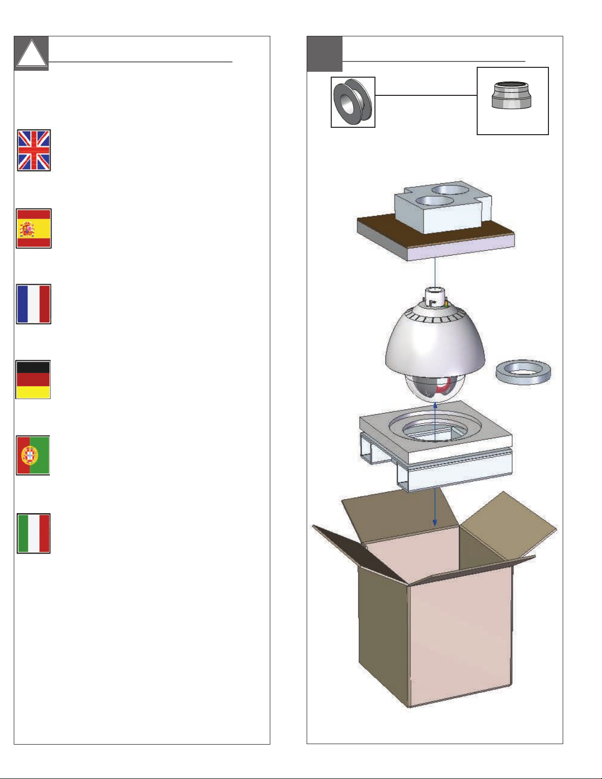
2
1
•Special anti-seize tape
“DO NOT REMOVE”
1
2
1
Teflon tape
ensure a tight seal and to prevent galling.
• Cinta de Teon™ se envuelve alrededor de las roscas de la tubería para
asegurar un sello hermético y para evitar el gripado.
• Ruban téon
étanchéité et éviter tout grippage.
• Teonband
zu gewährleisten und zu verhindern Fressen.
• Fita de Teon
selagem apertada e para evitar escoriações.
™
• Teon
e per prevenire l'usura.
3
3
™
is wrapped around the pipe threads to
™
est enroulé autour des letages pour assurer une bonne
™
ist rund um die Rohrgewinde gewickelt, um eine Abdichtung
™
é enrolado em torno das roscas do tubo para assegurar uma
nastro è avvolto intorno le lettature per assicurare una buona tenuta
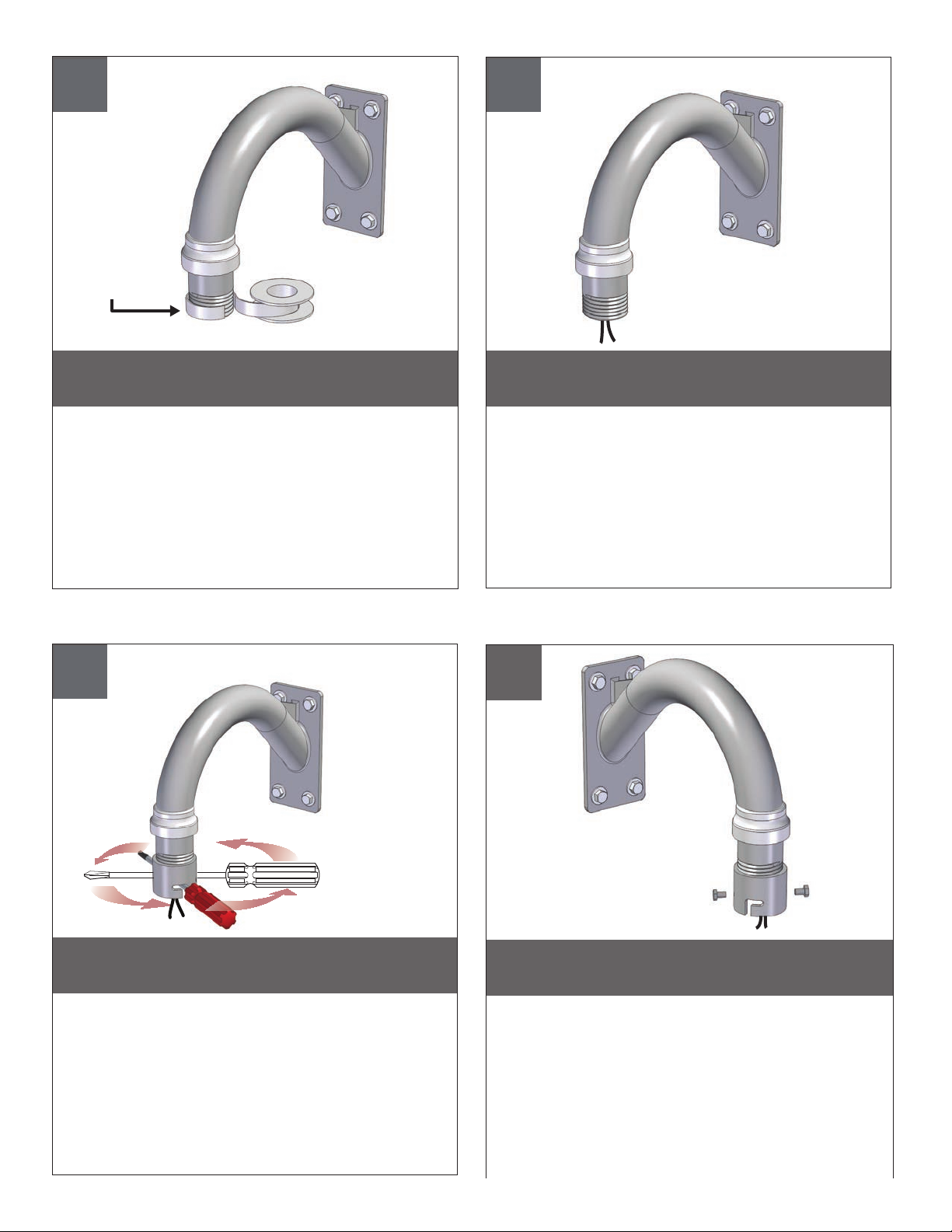
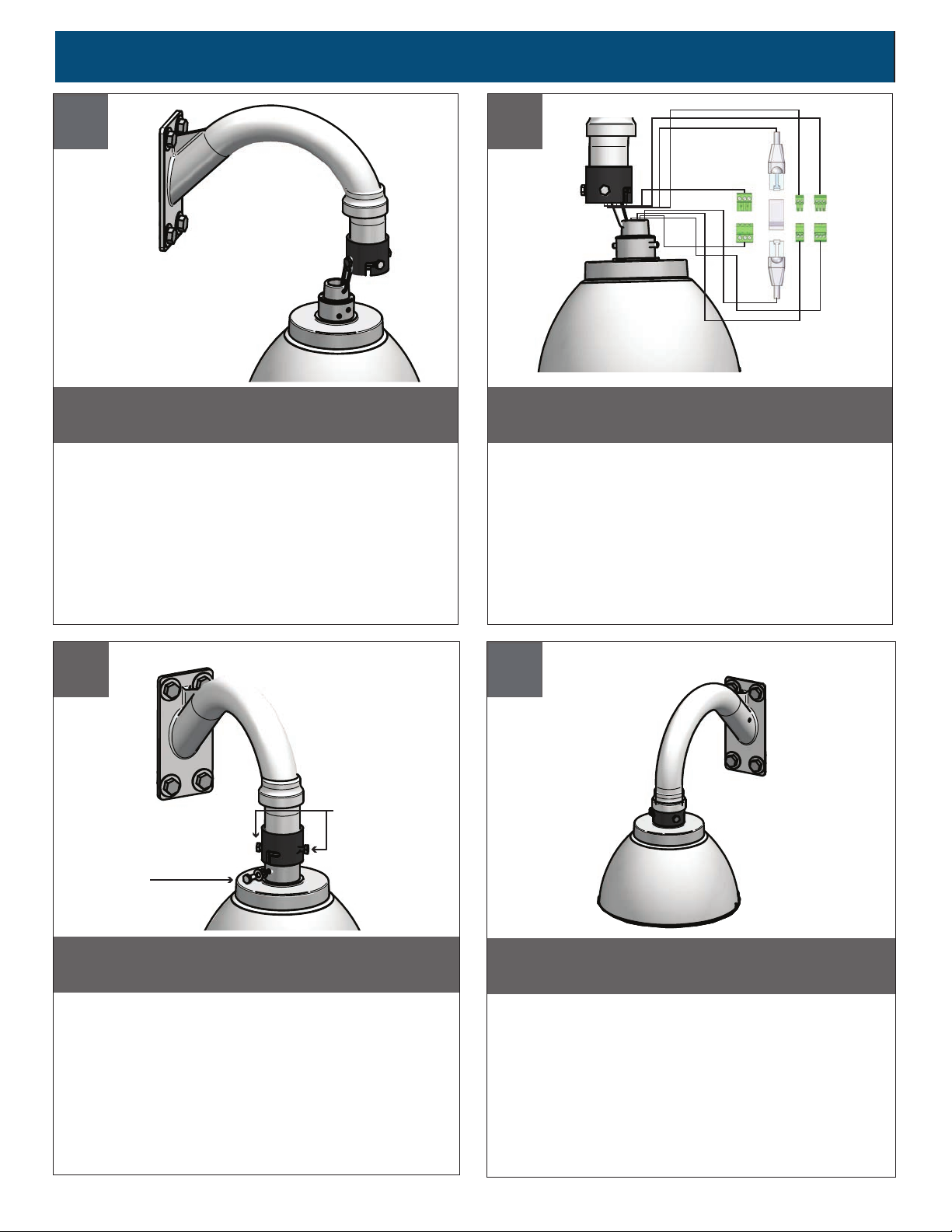
Securely mount bracket to wall. Pull wiring
through bracket and position grommet as shown.
• Con seguridad soporte del montaje a emparedar. Tire del cableado a través del
soporte y del ojal de la posición según lo demostrado.
• Solidement parenthèse de bâti à murer. Tirez le câblage par la parenthèse et le
canon isolant de position comme montré.
• Sicher Einfassung Haltewinkel wall. Ziehen Sie Verdrahtung durch Haltewinkel
und Position Gummimuffe, wie gezeigt.
• Firmemente suporte da montagem a wall. Puxe a ação através do suporte e do
ilhó da posição como mostrado.
• Saldamente staffa del supporto da wall. Tiri i collegamenti tramite la staffa ed il
gommino di protezione di posizione come indicato.
4
Screw the coupling tightly onto the pipe threads by
inserting a screwdriver through slots in coupling to
ease in final tightening.
• Atornillar el acoplamiento rmemente en las roscas de las tuberías mediante la inserción
de un destornillador a través de las ranuras de acoplamiento para facilitar el apriete nal.
• Vissez le couplage serré sur le letage de tuyaux en insérant un tournevis dans les fentes
de couplage à l'aise dans le serrage nal.
• Schrauben Sie die Kupplung fest auf die Rohrgewinde durch Einführen eines Schraubendrehers
durch die Schlitze in der Kopplung in dem endgültigen Anziehen zu erleichtern.
• Parafuse o acoplamento bem para as roscas pela inserção de uma chave de fenda através
ranhuras para facilitar o acoplamento no aperto nal.
• Avvitare l'attacco saldamente sulle lettature inserendo un cacciavite nelle fessure di
accoppiamento ad allentarsi nel serraggio nale.
Partially screw the (2) bolts into the coupling
to no more than flush with inside of coupling.
• Parcialmente atornillar los tornillos (2) en el acoplamiento a no más de enjuague
con el interior del acoplamiento.
• Partiellement visser les boulons (2) dans le raccord à pas plus de niveau avec
l'intérieur du raccord.
• Teilweise schrauben Sie die (2) Schrauben in die Kupplung nicht mehr als mit innen
der Kupplung zu spülen.
• Parcialmente aparafusar os parafusos (2) para o acoplamento a um máximo de lavar
com o interior do dispositivo de ligação.
• Parzialmente avvitare le (2) viti nel giunto a non più a lo con all'interno del giunto.
Page 7
Connecting Wall Bracket EXPF7
5
5
Loop the lanyard over the screw
head to temporarily hold housing.
• Loop la cuerda de seguridad en la cabeza del tornillo para mantener
temporalmente la vivienda.
• Enroulez le cordon autour de la tête de vis pour maintenir temporairement
le logement.
• Loop the Lanyard über den Schraubenkopf vorübergehend zu
halten Gehäuse.
• Laço da corda sobre a cabeça do parafuso para reter
temporariamente habitação.
• Avvolgere il cordino sulla testa della vite per memorizzare
temporaneamente alloggi.
6
10
Make the appropriate wiring connections
from the dome to the pendant.
• Hacer las conexiones de cableado de la cúpula de la pendiente.
• Faites le câblage de la coupole de la suspension.
• Nehmen Sie die entsprechenden Kabel-Verbindungen von der Kuppel auf den
Anhänger.
• Faça as conexões de cabos da cúpula para o pingente.
• Apportare le opportune connessioni cablaggio dalla cupola a ciondolo.
7
7
• Locking Screws
• Third Anti-Twist
Screw
Undo the lanyard, push housing up and twist.
Secure with the (2) locking bolts and washers.
Add third anti-twist screw if so equipped.
• Deshacer la cuerda de seguridad, empuje y gire hasta la vivienda. Asegure con los
tornillos de bloqueo (2) y las arandelas. Añadir tercero anti-torsión del tornillo si lo tiene.
• Défaire le cordon, appuyer sur le logement et torsion. Fixer avec les vis de blocage
(2) et les rondelles. Ajouter troisième anticorps anti-torsion vis si équipé.
• Lösen Sie die Leine, drücken Gehäuse und Touch. Sichern Sie mit den (2) Verriegelung
Schrauben und Unterlegscheiben. Fügen dritten anti-twist Schraube falls vorhanden.
• Desfazer o cordão, empurrar-se de habitação e torcer. Fixe com os parafusos (2)
de xação e arruelas. Adicionar parafuso anti-torção terceiro se assim equipado.
• Annulla il cordino, spingere abitazioni e torsione. Fissare con le (2) viti di
bloccaggio e le rondelle. Aggiungere un terzo anti-torsione vite se in dotazione.
8
8
Slide the grommet down over the coupling to aid
in preventing water from entering and complete
the assembly.
• Deslice la arandela hacia abajo sobre el acoplamiento para ayudar a evitar
la entrada de agua y completar el montaje.
• Glisser le passe-l vers le bas au-dessus de l'accouplement pour aider à
empêcher l'eau d'entrer et de compléter l'ensemble.
• Schieben Sie die Tülle nach unten über die Kopplung an der Verhinderung
das Eindringen von Wasser und den Zusammenbau zu erleichtern.
• Deslizar o ilhó metálico para baixo sobre o acoplamento para ajudar a impedir
a entrada de água e de completar a montagem.
• Far scorrere il gommino giù sopra il giunto per aiutare a prevenire l'ingresso
di acqua e completare il montaggio.
Page 8
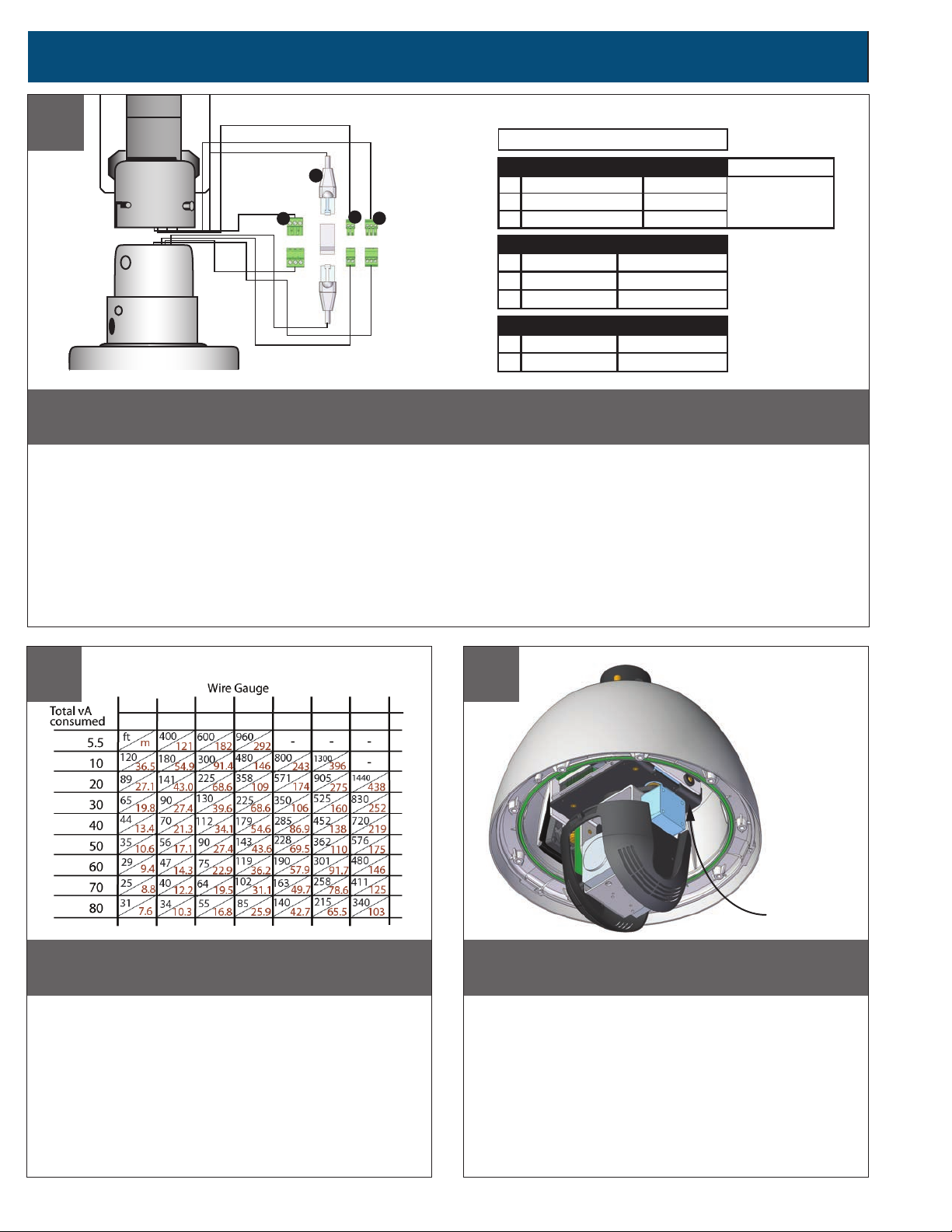
Wiring Connections for ALL Housings
9
A
C
B
Make the appropriate male and female connections.
• Haga las conexiones masculinas y femeninas apropiadas.
• Établissez les rapports masculins et femelles appropriés.
• Stellen Sie die passenden männlichen und weiblichen Beziehungen her.
• Faça as conexões masculinas e fêmeas apropriadas.
D
A
B
C
D
RJ45
1
2
3
1
2
3
1
2
24VAC
24Vac
24Vac
GND Green/White
Red
Orange
AUDIO
Speaker +
Audio GND
MIC +
Gray
Brown
White
ALARM
Alarm IN
GND
Blue
Violet
POWER
75 Watts
• Faccia i collegamenti maschii e femminili adatti.
12
10
,5 ,75 1,0 1,5 2,5 4 6
22 20 18 16 14 12 10
These are recommended maximum
The beam angle may be adjusted on the
distances for 24VAC with a 10% voltage drop.
bottom of the unit.
• Éstos se recomiendan las distancias máximas para 24VAC con
una gota del voltage del 10%.
• Ceux-ci sont recommandés des distances maximum pour 24VAC
avec une chute de tension de 10%.
• Diese werden maximale Abstände für 24VAC mit einem 10%
Spannungsabfall empfohlen.
• Estes são recomendados distâncias máximas para 24VAC com
uma queda de tensão de 10%.
• Questi sono suggeriti distanze massime per 24VAC con una
differenza de potenziale di 10%.
MM
AWG
12
11
2
Pan / Tilt Unit
The beam angle may be adjusted on the
To add SD card, you must remove Pan / Tilt unit.
bottom of the unit.
• Para añadir una tarjeta SD, debe quitar Pan / unidad Tilt.
• Pour ajouter carte SD, vous devez supprimer Pan / Tilt unité.
• Auf SD-Karte hinzufügen, müssen Sie entfernen Pan / Tilt-Einheit.
• Para adicionar cartão SD, você deve remover o Pan / Tilt unidade.
• Per aggiungere scheda SD, è necessario rimuovere Pan / Tilt unità.
Page 9
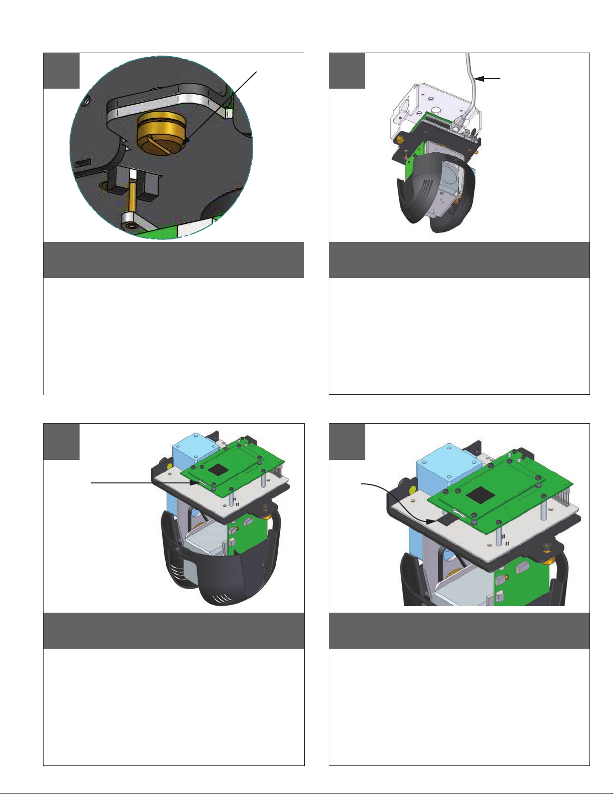
12
Captive Screw
13
Power Network Cables
To remove, loosen captive screw.
• Para quitarlo, tornillo cautivo suelto.
• Pour l'enlever, vis captive lâche.
• Zum Entfernen loser unverlierbare Schraube.
• Para remover, parafuso solto.
• Per rimuovere, sciolto vite imperdibile.
14
SD Card Slot
Disconnect cables, and remove
Pan / Tilt from base bracket in housing.
• Desconecte los cables y retire la cacerola / de la inclinación
del soporte de base en materia de vivienda.
• Débranchez les câbles, puis retirez Pan / Tilt de support de
base en matière de logement.
• Ziehen Sie die Kabel, und entfernen Pan / Tilt aus Grundträger
im Gehäuse.
• Desconecte os cabos e remover Pan / Tilt do suporte de
base em habitação.
• Scollegare i cavi e rimuovere Pan / Tilt dalla staffa base in custodia.
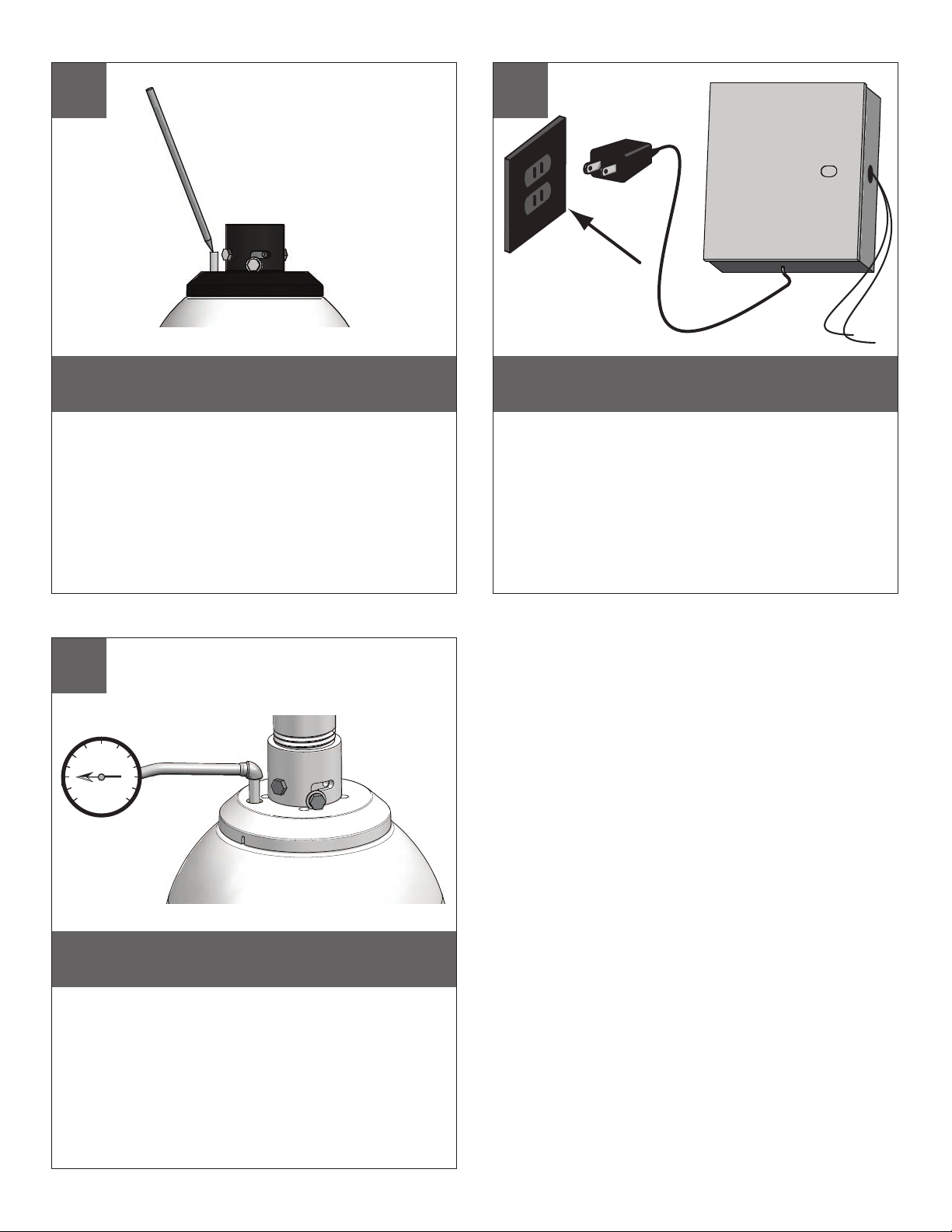
15
SD Card
(Not Supplied)
SD card slot is located at the base
of Pan / Tilt unit.
• Ranura para tarjetas SD se encuentra en la base? De la unidad
Pan / Tilt.
• Fente pour carte SD se trouve à la base? De l'unité de Pan / Tilt.
• SD-Kartensteckplatz an der Basis liegt der Pan / Tilt-Einheit.
• Slot para cartão SD está localizado na base? De Pan / Tilt unidade.
• Slot per scheda SD si trova alla base? Del Pan / Tilt unità.
Insert SD card if application requires.
• Inserte la tarjeta SD si la aplicación requiere.
• Insérez la carte SD si l'application l'exige.
• Legen Sie eine SD-Karte, wenn die Anwendung erfordert.
• Insira o cartão SD se a aplicação requer.
• Inserire la scheda SD se l'applicazione richiede.
Page 10

16
17
To install the dome align the tabs
and twist counter clockwise to secure.
• Para instalar la bóveda alinee las lengüetas y tuerza al revés a
la derecha para asegurar.
• Pour installer le dôme alignez les étiquettes et tordez contre dans
le sens des aiguilles d'une montre pour xer.
• Um die Haube anzubringen richten Sie die Vorsprünge aus und
verdrehen Sie sich entgegengesetzt nach rechts um zu sichern.
• Para instalar a abóbada alinhe as abas e torça-as contra no sentido
horário para xar-se.
• Per installare la cupola allinei le linguette e torca contro in senso
orario per ssare.
150
200
18
Regulator
50
100
0
250
PSI
300
Pressure
Gauge
Air Chuck
Hose
Hand tighten the screws on the dome.
Recommended torque 12 inches/lb (1.35Nm).
• La mano aprieta los tornillos en la bóveda. Esfuerzo de torsión
recomendado 12 inches/lb (el 1.35Nm).
• La main serrent les vis sur le dôme. Couple recommandé
12 inches/lb (1.35Nm).
• Hand ziehen die Schrauben an der Haube fest. Empfohlene
Drehkraft 12 inches/lb (1.35Nm).
• A mão aperta os parafusos na abóbada. Torque recomendado
12 inches/lb (1.35Nm).
• La mano stringe le viti sulla cupola. Coppia di torsione suggerita
12 inches/lb (1.35Nm).
19
Air Chuck
Tank
Valve
Nitrogen
Tank
When pressurizing unit be sure to set the
gauge or regulator from 10-20psi (.7-1.4bar).
• Al presurizar la unidad esté seguro de jar el calibrador o el
regulador de 10-20psi (.7-1.4bar).
• En pressurisant l'unité soyez sûr de placer la mesure ou le
régulateur de 10-20psi (.7-1.4bar).
• Wenn Sie Maßeinheit unter Druck setzen, seien Sie sicher,
die Lehre oder den Regler von 10-20psi (.7-1.4bar) einzustellen.
• Ao pressurizar a unidade seja certo ajustar o calibre ou o regulador
de 10-20psi (.7-1.4bar).
• Nel pressurizzare l'unità sia sicuro regolare il calibro o il regolatore
da 10-20psi (.7-1.4bar).
Place the air chuck on the tank valve and
begin lling until pressure relief valve opens.
• Coloque la tirada del aire en la válvula del tanque y comience a
llenar hasta que la válvula de descarga de presión se abre.
• Placez le mandrin d'air sur la valve de réservoir et commencez à
remplir jusqu'à ce que la valve de décompression s'ouvre.
• Setzen Sie die Luftklemme auf das Behälterventil und fangen Sie an
zu füllen, bis Druckablaßventil sich öffnet.
• Coloque o mandril do ar na válvula do tanque e comece a encher-se
até que a válvula de escape de pressão abra.
• Disponga il mandrino dell'aria sulla valvola del carro armato e cominci
a riempirsi no a che la valvola limitatrice della pressione non si apra.
Page 11
20
12
21
Open the relief valve. To drain all air from
the housing press the valve 3 times.
• Abra la válvula de descarga. Drene todo el aire de la cubierta y de
la repetición 3 times dos veces para quitar toda la humedad.
• Ouvrez la soupape de sécurité. Évacuez tout l'air le logement et la
répétition 3 times pour enlever toute l'humidité.
• Öffnen Sie das Sicherheitsventil. Lassen Sie alle Luft aus dem Gehäuse und
der Wiederholung zweimal ab, um alle Feuchtigkeit zu entfernen 3 times.
• Abra a válvula de escape. Drene todo o ar da carcaça e do repeat 3
times para remover toda a umidade.
• Apra la valvola di sato. Vuoti due volte tutta l'aria 3 times
dall'alloggiamento e dalla ripetizione per rimuovere tutta l'umidità.
22
15
20
10
5
25
PSI
30
0
The beam angle may be adjusted on the
Power up the unit.
bottom of the unit.
• Energía encima de la unidad.
• Puissance vers le haut de l'unité.
• Energie herauf die Maßeinheit.
• Poder acima da unidade.
• Alimentazione sull'unità.
After purging check the housing
pressure. It should be around 5psi (.34bar).
• Después de purgar el cheque la presión de la cubierta.
Debe estar alrededor de 5psi (34bar).
• Après la purge du contrôle la pression de logement.
Elle devrait être autour de 5psi (34bar).
• Nachdem Überprüfung der Gehäusedruck bereinigt worden ist.
Sie sollte um 5psi (34bar) sein.
• Após ter removido a vericação a pressão da carcaça.
Deve ser em torno de 5psi (34bar).
• Dopo l'eliminazione dell'inceppo del controllo la pressione
dell'alloggiamento. Dovrebbe essere intorno a 5psi (34bar).
Page 12
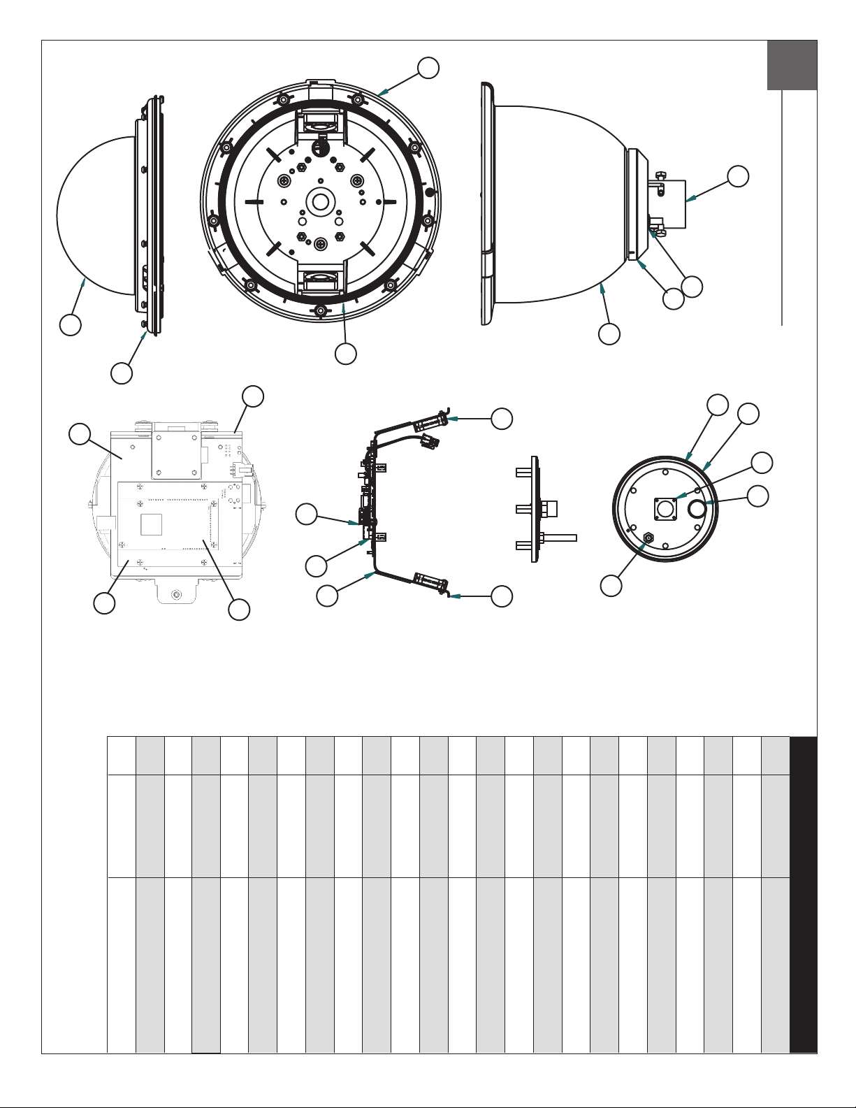
1
Replacement Parts List
2
4
3
7
1
5
6
21
9
17
8
20
10
11
15
14
12
19
18
13
16
N/S Sunshield
19 RP76VL2030 Camera Adapter
20 RP76VL2020 P/T Pan PCB
21 RPVL4107 Base Bracket
N/S WM20G Goose Neck (SOLD SEPARATELY)
18 RP76-ENE100 Network PCB
17 RPFD080 Blower
14 RPVL1798a ½" Spacers (Set of 4)
15 RP76VLZ024 PoE Board / with Surge
16 RPFD060 Main Bracket Assembly
12 RP95VALV07 Tank Valve
13 RP72HT3636 PoE Heater
10 RP70PT07a Hermetic Connector, Gasket, Cable
11 RP95VALV08 5 to 7 psi Pressure Relief Valve
7b RCTPFD7 Tinted Dome with sealing O-Ring
8 RPPVL4076 Internal Sealing Bracket
9 RP96RSORG10 Small O-Ring 4.5"
5 RP96RSORG11 Main O-Ring 9.25"
6 RPPFDTR01 Trim Ring w/o Dome
7 RPDC4357NX
Clear Nylon Dome with
sealing O-Ring
3 RPVL1802 Plastic Rain Shroud
4 RPVL1795 Tank Valve Gasket
1 RPPFD040 Housing Top
2 RPVL1938 Removable Pendent Coupling
Part No. Description
Page 13

TABLE OF CONTENTS
Software Sections
Moog Discovery Tool ...................................................... ..................................................................................................... 1.0.0
Using the Moog EXO Web Application ............................. ..................................................................................................... 2.0.0
System Status ............................................................... ..................................................................................................... 2.1.0
System Conguration ..................................................... ..................................................................................................... 2.2.0
Conguration / Date Time ............................................... ..................................................................................................... 2.2.1
Conguration / Network .................................................. ..................................................................................................... 2.2.2
Conguration / Network / DHCP ...................................... ..................................................................................................... 2.2.3
Conguration / Network / Host Name Conguration-NPT .. ..................................................................................................... 2.2.4
Conguration / Network / HTTP ....................................... ..................................................................................................... 2.2.5
Conguration / Network / API - Bonjour ........................... ..................................................................................................... 2.2.6
Conguration / Network / SNMP Conguration ................. ..................................................................................................... 2.2.7
Conguration / Network / RTSP Conguration .................. ..................................................................................................... 2.2.8
Conguration / Network / Multicast ................................. ..................................................................................................... 2.2.9
Conguration / Video In .................................................. ..................................................................................................... 2.3.0
Conguration / Video In / Video Input ............................... ..................................................................................................... 2.3.1
Conguration / Video In / Sensor ..................................... ..................................................................................................... 2.3.2
Conguration / Video In / Video Compression ................... ..................................................................................................... 2.3.3
Conguration / Video In / Point to Point ............................ ..................................................................................................... 2.3.4
Conguration / Video In / Text Overlay .............................. ..................................................................................................... 2.3.5
Conguration / Video In / Motion Detection ...................... ..................................................................................................... 2.3.6
Conguration / Video In / Privacy Zones ........................... ..................................................................................................... 2.3.7
Conguration / Audio In .................................................. ..................................................................................................... 2.3.8
Conguration / Audio Out ............................................... ..................................................................................................... 2.3.9
Conguration / Recording ............................................... ..................................................................................................... 2.4.0
Conguration / User Accounts ......................................... ..................................................................................................... 2.4.1
Maintenance ................................................................. ..................................................................................................... 3.0.0
Live Viewer .................................................................... ..................................................................................................... 4.0.0
Live Viewer Pan / Tilt and Presets ................................... ..................................................................................................... 4.1.0
Recording ..................................................................... ..................................................................................................... 5.0.0
Performing Batch Firmware Update ................................ ..................................................................................................... 6.0.0
Point to Point Connections .............................................. ..................................................................................................... 7.0.0
Troubleshooting Guide .................................................... ..................................................................................................... 8.0.0
Page 14

SOFTWARE SETUP
1.0.0 Moog Discovery Tool
By factory default, the Moog EXO Camera is congured in DHCP. If you are not using a DHCP server it will automatically allocate itself
an APIPA (Automatic Private IP Addressing) address in the range 169.254.0.1 to 169.254.255.254 with subnet mask 255.255.0.0.
Initial device network conguration is done via the Moog Discovery Tool (MDT), a tool provided by Moog that can be found on the
company’s web site and on the ash drive supplied with each camera system. The ash drive also contains a copy of Microsoft
Silverlight 5. Both programs should be installed on the your local server.
The MDT plays 3 important roles:
1. Discovery of all Moog EXO Cameras
2. Allows for remote conguration of the IP address and subnet mask
3. Permits batch rmware upgrade of all common EXO devices
Note: Silverlight is a free plug in and is required to interface with the Moog EXO Web brower.
Once your device is installed on your network and powered up, launch MDT from any computer on the network and the following window
will be displayed:
The MDT supports 2 ways to discover a device. The rst way doesn’t need any conguration and uses the Bonjour discovery protocol.
In order to be able to discover a device via Bonjour, the network must support multicast delivery.
If it is not the case, you can use the second way, which is the Unicast Discovery. The Unicast Discovery can be congured by using the
“Unicast Discovery” conguration form. This conguration form is available via the Admin / Unicast Discovery menu option.
Page 15

To congure the Unicast Discovery, add one or more IP address ranges. The Unicast Discovery tries to reach a device at a specic IP
address in the congured ranges. The discovery can be a long process if the range of IP addresses is large and the device is at the end
of the range. To accelerate the discovery, add several small ranges of IP addresses. The ping timeout option can be increased for a high
latency network.
The MDT will display as many devices as it discovers on the network
If no DHCP server was able to assign an IP address to a Moog EXO Camera, it will appear in the MDT device list with an APIPA address
(169.254.*.*). If a Moog EXO Camera displays an APIPA address it must be congured with a valid IP address before it can be remotely
congured by selecting the ‘’Assign IP address’’ from the selection list and conguring the TCP / IP settings.
Page 16

To assign IP Address, update rmware, or congure Moog web interface, right click on highlighted serial number / Mac Address.
Assign IP Address(es)
Once the IP information is set, the Silverlight web application served by the EXO Camera can be launched from the MDT or directly in your
web browser by typing the device’s IP address in the address bar. You can start to use your networked video management system for nal
system conguration or you can congure advanced parameters using the Moog EXO web based management.
Page 17

2.0.0 Using the Moog EXO Web Application
Application
When entering the Web Application, the following window will be displayed. You will be asked a username and password. The default User
name and Password is ‘admin’.
(To reset the user name and password see / Congurations / User Accounts)
Page 18

2.1.0 System Status
Status Window
Main Menu Tabs
System Status - 2.1.0
Conguration - 2.2.0
Maintenance - 3.0.0
Live Viewer - 4.0.0
Recording - 5.0.0
Upon successfully logging into the web interface, a welcome screen will be displayed. The welcome screen shows general device health
status as well as rmware version and system uptime.
Page 19

2.2.0 System Conguration
Conguration / System
Under the Conguration section, select the System tab to perform the following operations:
• View product model information, current rmware version and serial number.
• Specify a custom name; this name can be used by third-party software to display a selected name for the device.
Enable edge recording by checking the box “Use Recorder Module” checkbox. Disabling edge recording will accelerate
the device’s boot time.
To enable edge recording an SD card must be added to the camera interface card, located on the EXO pan/tilt device.
-
SD cards are not provided as a standard feature. Directions for installing the SD card are provided in the rst section
of this installer manual. Edge recording set up is done through the Recording Tab in the Live Viewer EXO screen.
Note: Recording menu will only be displayed when user recorder module check box is selected. You must save,
and then reboot to complete selection.
SD Card: Use 2GB to 32 GB Micro SD Card of class 6 or above. You must make sure the card is formatted to
FAT32 or EXT3.
Page 20

2.2.1 Conguration / Date Time
Under the Conguration section, select the Date Time tab to perform the following operations:
• Set the time zone in which the device is operating.
• Manually set the current date and time for the device’s internal clock.
• Note: For an accurate time stamp, you must sync UTC Time.
Conguration / Network
2.2.2 Conguration / Network
Page 21

2.2.3 Conguration / Network / DHCP
Under the Conguration section, select the Network tab to perform the following operations:
• Set the encoder’s IP parameters; DHCP or static IP information.
• Congure an NTP server to allow the device to automatically update its internal clock using an NTP server.
2.2.4 Conguration / Network / Host Name Conguration-NPT
NPT Server- use when desiring to have local network time as default, to do so you must…….
2.2.5 Conguration / Network / HTTP
• Change the device’s HTTP conguration, Note: Avoid changing these settings unless absolutely necessary.
Page 22

NOTE:
2.2.6 Conguration / Network / API- Boujour
To control the EXO Camera system with a VMS software system, you must enable the required Network APIs. Enable PSIA
•
or GENETEC API depending on which VMS platform you intend to use with the device. Disabling any unrequired APIs will
accelerate boot time.
• Note: ONVIF standard is built in and does not require activation. If using ONVIF you do not need to select an API.
• Set Bonjour discovery protocol settings.
• Modify SNMP settings to match with any SNMP software you wish to use for monitoring the device.
2.2.7 Conguration / Network / SNMP Conguration
2.2.8 Conguration / Network / RTSP Conguration
2.2.9 Conguration / Network / Multicast
If using Mulitcast output, Insert Multicast start IP, and select start port.
Page 23

2.3.0 Conguration / Video In
2.3.1 Conguration / Video In / Video Input
Under the Conguration section, select the Video In tab to perform the following operations:
Digital format – choices are, 720 30fps, 720 60fps, 1080 30fps, 1080 25fps. Note max camera output with WDR Active is 15fps (1080p).
2.3.2 Conguration / Video In / Sensor
Congure camera bloc / sensor parameters. These parameters will also be saved to the camera bloc itself if possible:
Use the narrow pull down function for vertical and horizontal rotation of the image.
Page 24

(Note: Activating WDR at 1080P will reduce maximum frame rate to 15fps.)
Frame per sec (fps):
Congure video compression parameters for any of the three available codec instances (Primary H.264, Secondary H.264 and
MJPEG). Most VMS software solutions will interact with these parameters and thus it is suggested to leave these at default values
in the web interface.
VBR aggressiveness however is unique to Moog EXO Cameras and proposes various levels (disabled to aggressive) of motion triggered
rate control. The more aggressive the setting, the more variation motion will have on the rate control. It is strongly suggested to disable
VBR aggressiveness for low bit rate scenarios (below 1Mbps) as this parameter may negatively affect perceived video quality.
2.3.3 Conguration / Video In / Video Compression
Set Quantization (QP) level to desired rate. The higher the number the greater the compression. (16 very low, 51 very high)
Frame Rate - Allows you to specify the frame rate to be used by the codec.
Rate Control -
Min/Max QP -
VBR Aggressiveness -
➞
Allows you to choose between Variable Bit Rate and Constant Bit Rate. The rst option will instruct the H.264
codec to dynamically adjust the bit rate in order to meet both the target quality (QP) and frame rate settings.
The second option will instruct the H.264 codec to prioritize target bit rate and vary quality (QP) rst and frame
rate as a last resort.
This parameter allows you to specify the compression range that the codec will use to determine image quality
during compression. In order to force a specic quality setting, you can set the minimum and maximum to the
same value. The lower the value, the better the quality will be.
This parameter allows you to specify if the codec should take into account the level of motion in the image for bit
rate calculations. You can select from Conservative, Moderate and Aggressive options for this setting. Using the
Conservative option, the codec will allow bit rate to drop up to ¾ of the congured target bit rate when no motion
is detected in the image. Using the Moderate option, the codec will allow bit rate to drop up to ½ of the congured
target bit rate when no motion is detected in the image. Using the Aggresive option, the codec will allow bit rate to
drop up to ¼ of the congured target bit rate when no motion is detected in the image. You can disable this feature
by selecting the disabled option.
Page 25

2.3.4 Conguration / Video In / Point to Point
Congure point to point video connections (up to three) for creating persistent video streams from the encoder to
•
a network endpoint.
2.3.5 Conguration / Video In / Text Overlay
To insert a text overlay:
• There are (2) available strings (Text blocks). Select string.
• Select string size.
• For string position click mouse inside string position box.
o Text bar will appear on video image.
o If you wish to relocate, simply click in desired position.
o Type desired text into String Text Box.
o Press Save Button.
Text Box
Page 26

2.3.6 Conguration / Video In / Motion Detection
Select from 1 of 4 available regions:
• With mouse click on region position box.
• Bring mouse pointer to view window and drag box around area for motion detection.
• Select desired Frame Count, Sensitivity and Thresholds.
• Press “Save” button to store information.
• You can select up to (4) separate “Motion” windows.
- Frame count: Number of frames required to trigger motion
- Sensitivity: No sensitivity, 100 MAX sensitivity
- Threshold: % of image required to trigger, both threshold must have a value; “off” value must be lower than “on”.
Page 27

2.3.7 Conguration / Video In / Privacy Zones
Privacy Zones are used to block out video in areas view is not permitted or desired.
To add a Privacy Zone:
• Select the Zone to be identied with privacy area. There are up to 16 zones available.
• With the mouse, click on Privacy Zone Position Box.
• Move mouse pointer over the Image Window, click and draw a box on the area you wish to see video.
• Press the “Save” button to store.
Page 28

2.3.8 Conguration / Audio In
Under the Conguration section, select the Audio In tab to perform the following operations:
• Congure audio input compression parameters.
•
Congure point to point audio connections (up to three) for creating persistent audio streams from the encoder to
a network endpoint.
Page 29

2.3.9 Conguration / Audio Out
Under the Conguration section, select the Audio Out tab to perform the following operations:
• Congure audio output parameters.
• Congure a point to point audio connection for receiving a persistent audio stream from a network endpoint.
Page 30

2.4.0 Conguration / Recording
Page 31
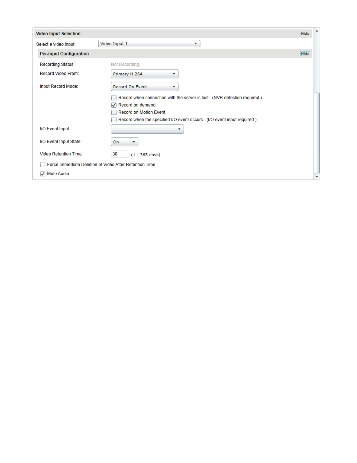
Note: Recording Menu will NOT be visible unless activated; see 2.20 System conguration.
• Grooming mode; Select method to remove les from full SD card chronological will remove old les rst.
Page 32

2.4.1 Conguration / User Accounts
Under the Conguration section, select the User Accounts tab to perform the following operations:
• Select the web interface’s authentication method. A dual passphrase is made available for additional security.
• Manage user accounts which have access to the device.
User Roles:
Administrator: All is available
Superuser: All is available except the user management
Poweruser: All is available except the user management and the recording
User:
Only access basic operations: system information, live video (no ptz controls), date time management
and password change
Page 33

3.0.0 Maintenance
This section describes how to update your Moog EXO Cameras to newer rmware versions from the web application.
1. To nd the latest le go to www.moogS3.com/technical-support/.
2. Click on “EXO PTZ Camera Firmware” - click, save le.
3. Navigate to your device’s web application using your favorite web browser.
4. Click on the Maintenance tab.
Click on the Update button, locate downloaded rmware. You will be asked for the rmware update le; please select the
5.
.iof le which was provided by Moog.
6. You will see the following messages indicating the status of the update:
o Firmware upload in progress... (100%)
• Lasts around 95 seconds.
o Firmware uploaded. Saving to internal storage... (0%)
• Lasts around 45 seconds.
o Validating and decompressing rmware... (0%)
• Lasts around 105 seconds.
o Firmware ready for installation. Rebooting device... (0%)
• Web page will disconnect from device until device has rebooted.
• You will be prompted for login once the device is up again.
• Lasts around 110 seconds.
o Testing rmware stability... (26%)
• Lasts 120 seconds.
o Firmware update complete. (100%)
Page 34

Use Live View for:
• Live Camera View
• Start and Stop Recording
• Pan / Tilt and Camera Control
• Setting Presets
• Adjust View Scale
4.0.0 Live Viewer
To enable live you must activate by pressing the “Play” button.
To adjust viewing scale for 1024 x 768 monitor, press smaller view.
Play Button
Page 35

4.1.0 Live Viewer Pan / Tilt and Presets
Pan/Tilt
Controls
Lens Control
• Pan Tilt Control; To operate Press Arrow in desired direction of movement.
• Use Pan / Tilt speed slider controls to vary Pan / Tilt speed control, to increase speed, slide control knob to the right.
• Lens Funtion use +/- buttons to update Iris, Zoom and Focus.
• Preset Functions.
o First Select Preset Number.
o Then position Camera and lens to desired position.
o Press “Set” to save Preset.
o For additional presets, repeat process.
Preset
Controls
o To clear, select desired preset press “clear”.
To establish a home position – move the camera to desired position, press set home position – Pan Tilt will use this as default
•
start up position.
Page 36

5.0.0 Recording
To activate recording mode you must go to Conguration / System / Use Recorder Mode. Click “Use Recorder Mode” checkbox. This will
activate addional Recording controls in the recording window. You must “Save” and then “Reboot” after making this change.
> Select Video Input
> Select Date of the Recording
Then select the led clip you wish to view
Note: You must have either VLC Player or Windows Media Player installed.
Page 37

6.0.0 Performing Batch Firmware Update
This section describes how to perform a batch update of multiple Moog EXO Camera devices to newer rmware versions from the MDT.
The batch rmware update works by starting a rmware update session. Only one session at time is allowed and only 20 devices can be
selected by session.
From the MDT, select one or more devices of the same type.
By using the right mouse button on the selected devices, choose the “Firmware Update” menu option.
Page 38

To start a rmware update session, choose the “.iof” le corresponding to the new rmware by clicking to the “Select File …” button.
Once selected, click the “Start” button.
Once started, the “Firmware Update Session” window shows the progress of the rmware update. This window can be closed at any
moment without losing the current session.
Page 39

If closed, the progress of the current session can be followed by reopening the “Firmware Update Session” window by clicking the button
from the “Tools” toolbar.
Once done, clear the current session from the “Firmware Update Session” window and restart a new session if needed.
7.0.0 Point to Point Connections
Point-to-point connections between a Moog EXO Camera and a Decoder can be congured using the device’s web application.
In the Moog EXO web application, in the Conguration section, go to the Video In tab. Scroll down all the way to the bottom of the
conguration page. The last 3 sections are named Point to Point 1, 2 and 3.
Here’s a quick overview of the settings available for a connection:
• Enabled: Indicates whether this connection is to be used.
• Description: Free-form user description of the connection, not used by the device.
Encoder: Indicates which video feed is to be sent over the point-to-point connection. Possible values include «Primary H.264
•
» and «Secondary H.264». These values refer to the encoders congured in previous sections of the same web page.
Destination IP: Address where to send the video. This is usually the address of a Decoder. The destination can also be a
•
multicast group address. DNS names are not yet supported, only IP addresses.
• Destination Port: Network port where to send the video. This value must match the port value in the Decoder.
Once all the settings have been set, click on Save at the bottom of the page to apply them. The Moog EXO Camera then creates or updates
the connection as needed.
8.0.0 Troubleshooting Guide
• Device does not seem to boot-up
o Verify that a 24Vac power supply is connected to the device.
o When a valid power source is detected, the status Pan / Tilt LED, power will light up GREEN.
• Cannot discover the device or communicate via the network
Dynamic discovery of the Moog Camera requires multicast networking to be supported by your network and switch
o
equipment. (Bonjour protocol)
o Make sure you have connected the device to your network.
 Loading...