

Page 1

DS2110
DIGITAL CONTROLLER
INSTALLATION & USER’S MANUAL
Document No.: CDS7324 (formerly LSF-0819)
Revision: A
Date: May 2011
INDUSTRIAL CONTROLS DIVISION
Page 2

TABLE OF CONTENTS T/C -1
CHAPTER 1.0 OVERVIEW............................................................................................................. 1-1
1.1 Introduction...................................................................................................................... 1-1
1.2 DS2110 Models................................................................................................................. 1-2
1.3 Environmental Specifications......................................................................................... 1-4
1.4 Design Standards............................................................................................................. 1-5
1.5 Power Ratings Specifications.......................................................................................... 1-6
1.6 General functional specifications................................................................................... 1-9
CHAPTER 2.0 SAFETY & EMC INSTRUCTIONS.......................................................................... 2-1
2.1 General.............................................................................................................................. 2-1
2.2 Safety Regulations............................................................................................................ 2-2
2.3 Electromagnetic Compatibility........................................................................................ 2-12
2.4 UL Requirements ............................................................................................................. 2-22
CHAPTER 3.0 WIRING AND INSTALLATION............................................................................... 3-1
3.1 System Components........................................................................................................ 3-1
3.2 Equipment Mounting........................................................................................................ 3-5
3.3 Pow er Di ssipation ............................................................................................................ 3-15
3.4 DS2110 Connector Terminals ......................................................................................... 3-16
3.5 General System Wiring Guidelines................................................................................. 3-20
3.6 Sequence of Component Wiring Recommendations.................................................... 3-22
3.7 Three Phase AC Mains Power Source Configuration ................................................... 3-23
3.8 24V Backup Connection .................................................................................................. 3-29
3.9 Internal/External Regeneration (Regen) Resistors – Configurations .......................... 3-32
3.10 Motors – Installation ...................................................................................................... 3-36
3.11 DS2110 Control Inputs and Outputs............................................................................. 3-49
3.12 Communication Interface Wiring and Configuration .................................................. 3-54
3.13 Wiring Summary............................................................................................................. 3-55
CHAPTER 4.0 GETTING STARTED.............................................................................................. 4-1
4.1 Introduction...................................................................................................................... 4-1
4.2 Initial Preparation............................................................................................................. 4-1
4.3 Power Supply ................................................................................................................... 4-1
4.4 Installing Windrive ........................................................................................................... 4-2
4.5 Controller Access ............................................................................................................ 4-3
4.6 Motor Selection ................................................................................................................ 4-4
4.7 Regen Resistor Configuration ........................................................................................ 4-6
4.8 Acceleration Limits.......................................................................................................... 4-8
4.9 Parameter Utilities............................................................................................................ 4-9
4.10 Status and Faults ........................................................................................................... 4-10
4.11 High Power Application................................................................................................. 4-11
4.12 Autophasing.................................................................................................................... 4-12
4.13 Torque Mode Enable...................................................................................................... 4-13
4.14 Velocity Mode Enable .................................................................................................... 4-14
4.15 Oscilloscope................................................................................................................... 4-15
4.16 Pow er Down Sequence.................................................................................................. 4-20
TABLE OF CONTENTS
CDS7324
REV. A INSTALLATION & USER’S MANUAL
Page 3

TABLE OF CONTENTS T/C -2
TABLE OF CONTENTS
CHAPTER 5.0 FUNCTIONAL OVERVIEW..................................................................................... 5-1
5.1 Introduction ...................................................................................................................... 5-1
5.2 DS2110 Conventions........................................................................................................ 5-1
5.3 Power Interface Section................................................................................................... 5-2
5.4 Motor Configuration......................................................................................................... 5-8
5.5 Resolver Input .................................................................................................................. 5-13
5.6 Encoder Input................................................................................................................... 5-16
5.7 Commutation Module....................................................................................................... 5-21
5.8 Position Feedback............................................................................................................ 5-24
5.9 Velocity Feedback............................................................................................................ 5-25
5.10 Input and Output Functional Description..................................................................... 5-26
5.11 Control Loops ................................................................................................................. 5-34
5.12 Dri ve Monitoring & Fault Detection .............................................................................. 5-52
5.13 Self Protection................................................................................................................ 5-66
5.14 Parameter Storage ......................................................................................................... 5-67
APPENDIX A – DATA LOGGER.................................................................................................... A-1
APPENDIX B – GUI........................................................................................................................ B-1
B.1 Introduction...................................................................................................................... B-1
B.2 Getting Started/Common Features ................................................................................ B-2
APPENDIX C – RESTART INTERLOCK CIRCUITS...................................................................... C-1
C.1 Intended Application....................................................................................................... C-1
C.2 Restart Interlock Function .............................................................................................. C-2
C.3 Safety Requirements....................................................................................................... C-4
C.4 Restart Interlock Circuit.................................................................................................. C-5
C.5 Restart Interlock Connections........................................................................................ C-7
C.6 Safety Relays – Technical Data...................................................................................... C-9
C.7 Application Example....................................................................................................... C-10
C.8 Checking the Restart Interlock....................................................................................... C-13
C.9 External Consistency Checks ........................................................................................ C-14
C.10 Installation and Routine Test........................................................................................ C-15
APPENDIX D – MEZZANINE CARD INSTALLATION................................................................... D-1
APPENDIX E – ANALOG I/O MEZZANINE CARD........................................................................ E-1
E.1 Introduction...................................................................................................................... E-1
E.2 Overview........................................................................................................................... E-1
E.3 Configurations ................................................................................................................. E-1
E.4 Analog I/O......................................................................................................................... E-2
E.5 SSI Interface..................................................................................................................... E-4
E.6 Simulated Encoder/Resolver .......................................................................................... E-5
E.7 PLC Master – DS2110 Slave Arrangement..................................................................... E-7
E.8 Noise Reduction .............................................................................................................. E-7
CDS7324
REV. A INSTALLATION & USER’S MANUAL
Page 4

TABLE OF CONTENTS T/C -3
TABLE OF CONTENTS
APPENDIX F – DEVICENET™ MEZZANINE CARD...................................................................... F-1
F.1 Connector......................................................................................................................... F-1
F.2 Network Status................................................................................................................. F-1
F.3 Available Objects............................................................................................................. F-1
F.4 MacID and Baud Rate ...................................................................................................... F-2
F.5 Initial Motion Setup.......................................................................................................... F-2
F.6 Fieldbus Scaling Factors................................................................................................. F-2
F.7 Units.................................................................................................................................. F-3
F.8 PARAM UPDATE in.......................................................................................................... F-3
F.9 Implicit I/O......................................................................................................................... F-3
F.10 Parameter List ................................................................................................................ F-4
APPENDIX G – ETHERNET MEZZANINE CARD.......................................................................... G-1
G.1 Introduction ..................................................................................................................... G-1
G.2 Modes of Operation......................................................................................................... G-1
G.3 Changing IP Address for Ethernet Device .................................................................... G-2
G.4 Changing Commands and Status Registers................................................................. G-4
G.5 Allen-Bradley RSLogix Configuration with DS2110 ..................................................... G-6
CDS7324
REV. A INSTALLATION & USER’S MANUAL
Page 5
CHAPTER 1.0 Overview 1-1
1.1 Introduction
This section gives an overview of the available DS2110 models, ratings and general specifications.
Detailed outlines of installation and wiring, functionality, user interfaces and other technical data are
given in subsequent sections.
CAUTION: Repairs or modifications to the product by anyone other than a Moog
authorized repair facility may create unsafe operating conditions and will invalidate
the product warranty.
CDS7324 (FORMERLY LSF-0819)
Rev. A INSTALLATION & USER’S MANUAL
Page 6

CHAPTER 1.0 Overview 1-2
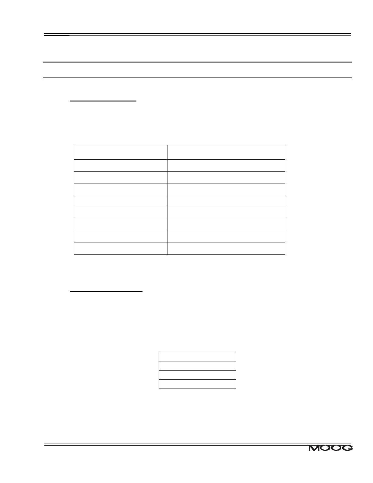
1.2 DS2110 Models
The DS2110 family is available in twelve base models, which cover a range of output current ratings.
DS2110 Base Model Amplifier Current Rating
Code Size Continuous
Maximum (Arms) Peak (A)
(Arms)
G362-x03 µA or A 3 6.4 9
G362-x04 A 4 8.5 12
G362-x06 µA or A 6 16 22
G362-x08 A 8 16 22
G362-010 B 10 29.7 42
G362-014 B 14 29.7 42
G362-020 C 20 31.8 45
G362-025 C 25 49.5 70
G362-030 C 30 63.6 90
G362-050 D 50 99.3 140
G362-060 D 60 127.6 180
G362-100 E 100 212.1 300
Table 1.1 DS2110 Family Models
The DS2110 family uses a 14 character coding system to identify the unique attributes of each model.
CDS7324 (FORMERLY LSF-0819)
Rev. A INSTALLATION & USER’S MANUAL
Page 7

CHAPTER 1.0 Overview 1-3
Page Intentionally Blank
CDS7324 (FORMERLY LSF-0819)
Rev. A INSTALLATION & USER’S MANUAL
Page 8

CHAPTER 1.0 Overview 1-4
1.3 Environmental Specifications
DS2110 Electronics
Maximum temperature
Storage: -25 C to 55 C (Class 1K4)
Transport: -25 C to 70 C (Class 2K3)
Surrounding air 0 C to 40 C
Relative humidity: 5 % to 85 %, non-condensing, 1 g/m3 to 25 g/m3, in accordance with
EN50178 class 3k3
Elevation: 1000m (3,300 feet); derate output 2% per 300m (1000 ft) above 1000m
(3300 ft)
Air pressure: 86 kPa to 106 kPa
Type of protection: Components must be installed into an enclosure. The enclosure must
provide at least IP54 per standard EN60529 or equivalent.
Pollution degree: Drive is suitable for installation in a Pollution Degree 2 environment.
Installed position: Vertical only.
Overvoltage protection class: Category 2 per standard VDE0110 / IEC664
Noise: Overall noise depends on the user installation and cabinet.
CDS7324 (FORMERLY LSF-0819)
Rev. A INSTALLATION & USER’S MANUAL
Page 9
CHAPTER 1.0 Overview 1-5
1.4 Design Standards
The DS2110 is CE-Marked under the EU's Low Voltage Directive. It has been designed to allow easy
compliance of customer's machines under the EU's EMC Directive (measures as directed in this
manual have to be taken to ensure EMC compliance). It is designed to the UL508C standard. The A
size DS2110 units are UL recognized. The DS2110 A-D sizes are UL listed.
The DS2110 has been designed to the following specific standards:-
IP Code EN 60529:1991
EMC EN 61800-3:1996 , EN 61800-3/A11:2000 (Second Environment)
UL UL508C with reference to UL840
Table 1.2 DS2110 Design Standards
CDS7324 (FORMERLY LSF-0819)
Rev. A INSTALLATION & USER’S MANUAL
Page 10
CHAPTER 1.0 Overview 1-6
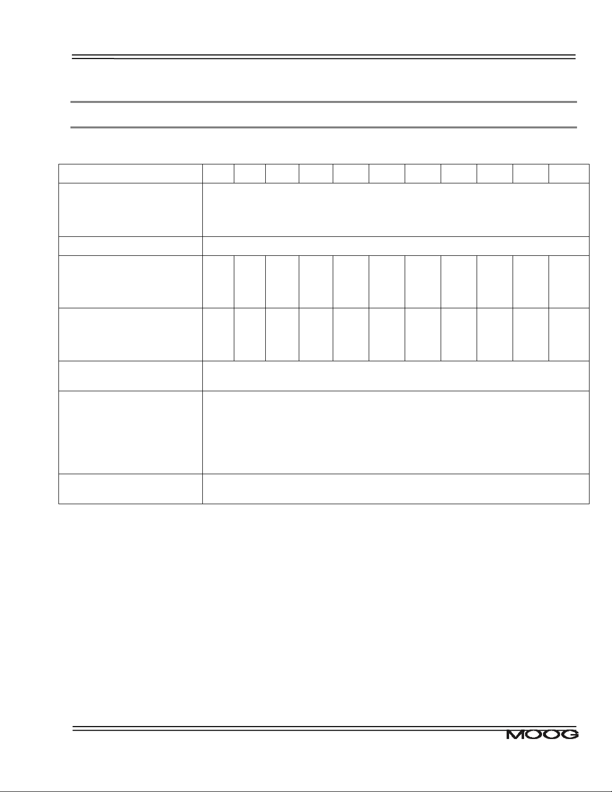
1.5 Power Ratings Specifications
Model : G362-x
A.C. Mains Input Range
Minimum
Maximum
Frequency Range
Internal Regeneration Power
Continuous Dissipation
Peak Dissipation @ 230Vac
Peak Dissipation @ 400Vac
External Regeneration Power
Continuous Dissipation
Peak Dissipation @ 230Vac
Peak Dissipation @ 400Vac
Softstart Peak Inrush
Current/Phase
Power Supply Fault Detection
3Amp 6Amp 8Amp 10Amp 14Amp 20Amp 25Amp 30Amp 50Amp 60Amp 100Amp
65Vac (110Vac -40%)
506Vac (440Vac +10%)
50 - 60Hz
150W
50W
1.3Kw
4.8kW
50W
1.2Kw
4.8kW
100W
1.3kW
4.8kW
100W
1.2kW
4.8kW
2.6kW
10.3kW N/A N/A N/A N/A N/A N/A N/A N/A
200W
2.8kW
11.3kW
240W
6.6kW
26.3kW
250W
4.4kW
17.5kW
370W
12.0kW
48.1kW
370W
12.0kW
48.1kW
370W
12.0kW
48.1kW
750W
14.4kW
57.8kW
750W
14.4kW
57.8kW
1kW
37kW
148kW
30Apk
D.C. Bus Overvoltage
D.C. Bus Undervoltage
Bridge Temperature Fault
Amplifier Short Circuit Protection
24V Logic Backup Monitoring
Voltage Discharge after A.C
Mains Removal
Bleed Resistors across high voltage section.
Table 1.3 DS2110 Power Ratings
CDS7324 (FORMERLY LSF-0819)
Rev. A INSTALLATION & USER’S MANUAL
Page 11
CHAPTER 1.0 Overview 1-7
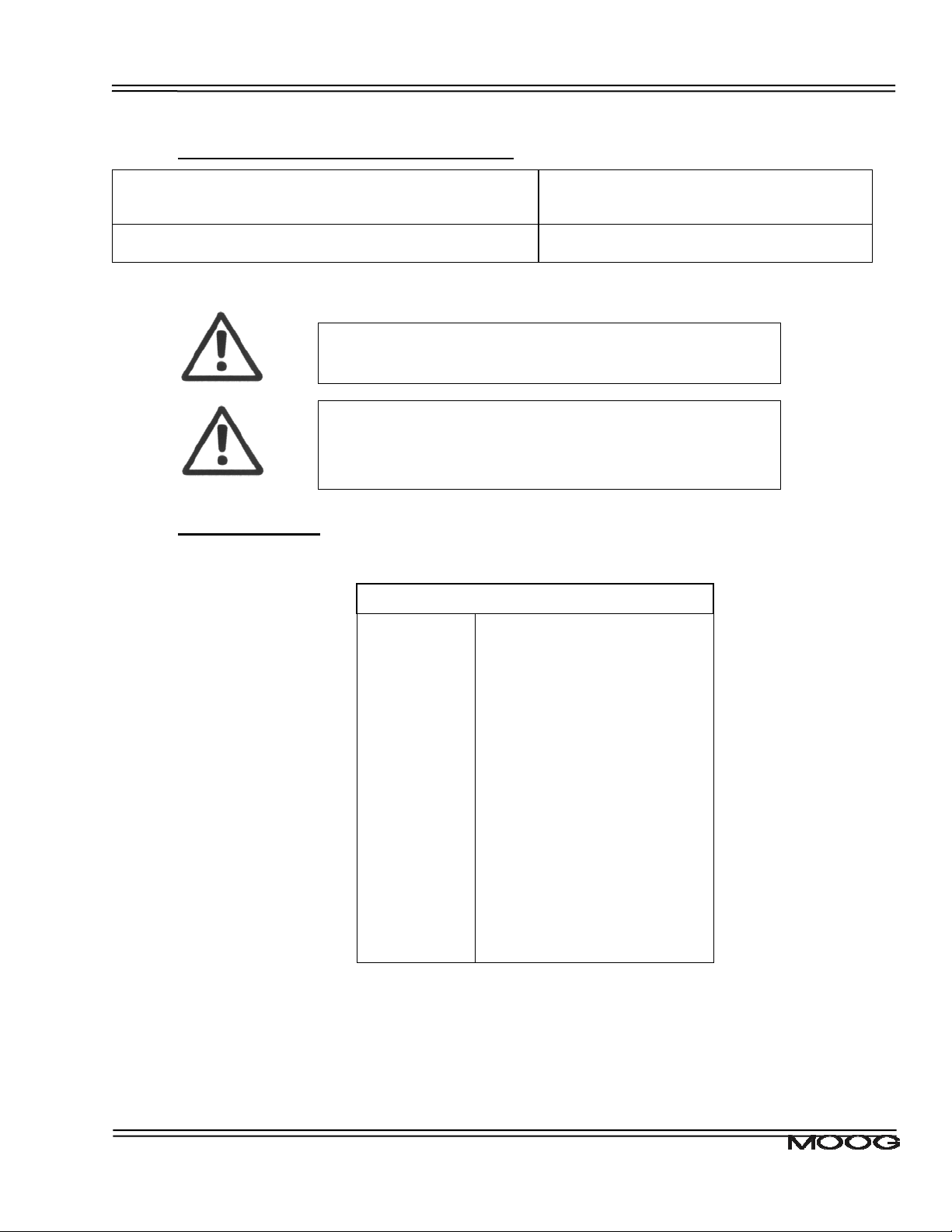
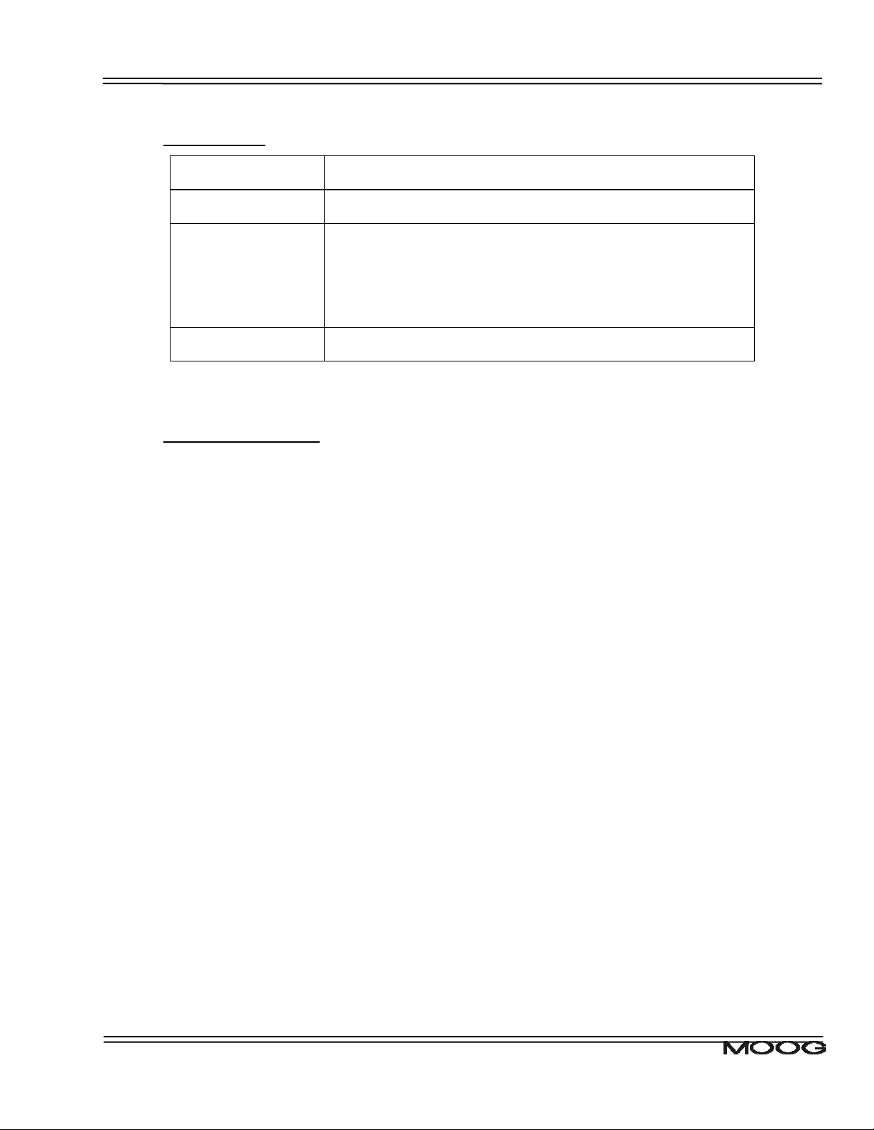
1.5.1 Optional Control Logic Backup Power
D.C. Bus Minimum Voltage
(below which 24Vd.c. Control Logic Backup supply is
needed)
24V Input
Table 1.4 DS2110 Control Logic Backup Power Ratings
An auxiliary 24V d.c. control logic backup supply is
MANDATORY for the –x003 & -x006 variants of the DS2110
product family.
The 24V Backup supply input is intended for use in the
secondary of a Class 2 supply. Alternatively, it should be
additionally fitted with a Listed Current limiting type fuse, rated
3A on the supply input to the device.
170Vd.c. (Generated from rectified 120Va.c.)
24Vd.c.± 10%
2.0A steady state
1.5.2 Power Amplifier
All current ratings are specified in ampere r.m.s. unless otherwise stated.
Power Amplifier Ratings:
G362-x03 3A continuous/9A peak
G362-x04 4A continuous/12A peak
G362-x06 6A continuous/15A peak
G362-x08 8A continuous/22A peak
G362-010 10A continuous/42A peak
G362-014 14A continuous/42A peak
G362-020 20A continuous/45A peak
G362-025 25A continuous/70A peak
G362-030 30A continuous/90A peak
G362-050 50A continuous/ 140A peak
G362-060 60A continuous/ 180A peak
G362-100 100A continuous/ 300A peak
Table 1.5 DS2110 Power Amplifier Ratings
Two levels of thermal protection which limit the peak current and the time for which it is available
protect the DS2110 drives. These are:
• RMS Protection,
• Thermal Foldback.
CDS7324 (FORMERLY LSF-0819)
Rev. A INSTALLATION & USER’S MANUAL
Page 12

CHAPTER 1.0 Overview 1-8
1.5.4.1 RMS Protection
The RMS protection acts to limit the current provided to the rated continuous current of the drive. Thus,
a G362-x006 cannot supply, on average, greater than 6Acontinuous RMS to the motor. The current to
the motor is averaged and if it exceeds the RMS rating, the drive limits the current command. If the
controller continuously demands current greater than the drive capability, the RMS protection will limit
the actual current supplied to the drive rating. The time for which peak current can be supplied is
dependent on whether the motor is stalled or running.
1.5.4.2 Thermal Foldback
Thermal foldback is implemented in the DS2110 drives to prevent the junction temperatures of the
amplifier bridge IGBT’s exceeding their maximum rated temperature. The thermal foldback is based on
a measure of the heatsink temperature and the mode in which the drive is operating (motor running or
stalled). As the heatsink temperature increases, the peak current capability of the drive is reduced to
ensure the IGBT die temperature cannot increase above the device maximum rating.
For the DS2110 D size, a simple thermal shutdown is implemented. These drives will report an
overtemperature fault once the measured heatsink temperature exceeds the maximum rating of the
drive.
CDS7324 (FORMERLY LSF-0819)
Rev. A INSTALLATION & USER’S MANUAL
Page 13
CHAPTER 1.0 Overview 1-9
1.6 General Functional Specifications
1.6.1 Digital Inputs (J2A)
• 8 Digital Inputs, user configurable
• Digital Input 1 Dedicated to High Power Enable
• All Optically Isolated, 12…36V Input Range.
• 5k input impedance.
STANDARD FUNCTION
High Power Enable Input High Power Enable Input
Auto / Manual Mode See Section 5.9
Torque / Velocity Mode Switch See Section 5.9
Brake Control See Section 5.9
CW Limit Switch See Section 5.9
CCW limit Switch See Section 5.9
Quick Stop See Section 5.9
Controlled Disable See Section 5.9
FIELDBUS OR INTERFACE SPECIFIC
Table 1.6 DS2110 Digital Inputs Overview : Standard Configuration
1.6.2 Digital Outputs (J2B)
• 3 Digital outputs, user configurable
• All outputs are Optically Isolated.
• Nominal ratings of 6V to 32V, 250mA
• Protected for supply range of –40V to 40V
• Short-circuit & reverse polarity protected
• Off-state leakage current <100μA at 0V
Standard Function
Limiting Function
Table 1.7 DS2110 Digital Outputs Overview
Drive Enabled
User defined
CDS7324 (FORMERLY LSF-0819)
Rev. A INSTALLATION & USER’S MANUAL
Page 14
CHAPTER 1.0 Overview 1-10
1.6.3 Standard I/O
Drive Ready (J2C)
Brake Control (J2D)
Motor Position
Feedback Type
(J3/J4)
Communications
Interfaces (J1)
Relay output, contact ratings: 36V, 100mA max.
Closed when drive is ready and has no faults.
2A, 24Vd.c. solid-state high-side drive for motor brake control.
Switched under user control or DS2110 software control
Resolver Encoder Types
• SSI
• Hiperface
• Analogue encoders
• Endat
• NRZ serial
RS232 Interface at 19200Baud
Table 1.8 DS2110 Standard I/O Summary
1.6.4 Variant Specific I/O
Refer to the appendix for details on a specific fieldbus variant.
CDS7324 (FORMERLY LSF-0819)
Rev. A INSTALLATION & USER’S MANUAL
Page 15

CHAPTER 1.0 Overview 1-11
Page Intentionally Blank
CDS7324 (FORMERLY LSF-0819)
Rev. A INSTALLATION & USER’S MANUAL
Page 16
p
y
CHAPTER 2.0 Safety & EMC Instructions 2-1
2.1 General
This user’s manual is intended to provide sufficient information on how to install Moog DS2110 electric
motor systems. Section 2.2 covers Safety and System Safeguards. Section 2.3 covers Electromagnetic
Compatibility (EMC). This user’s guide must be read and understood before applying power and
operating the equipment described.
This equipment must be installed and serviced only by duly qualified service personnel. All information
in this manual is directed towards such persons only. Individuals responsible for the installation of the
equipment described in this user’s guide must ensure;
1) only technically qualified individuals are employed to work on the installation,
2) these qualified individuals must have the accompanying documentation available at all times when
working on the installation and are obliged to use this documentation in a consistent manner, and
3) work on, or close to, the installation is prohibited for non-technically qualified individuals
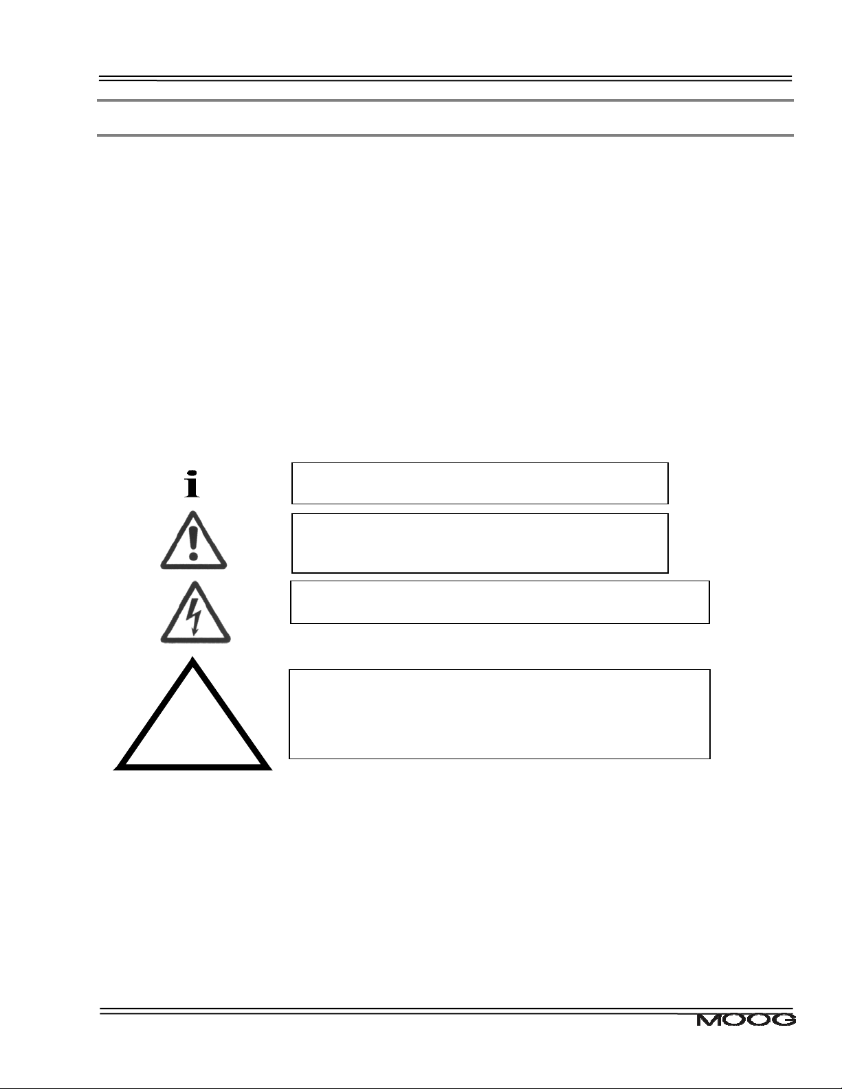
Throughout this user’s guide may be found NOTES, CAUTIONS, and WARNINGS and CECompliance-Required. They are defined as follows:
Required for
CE-Compliance
NOTES are general in nature and are intended to
em
hasise information.
CAUTIONS are to alert personnel to actions that could
cause equipment damage, resulting in the equipment
becoming unsafe.
WARNINGS serve to make personnel aware of potentially
hazardous actions that may result in personal injury or death.
CE-Compliance indicates where a particular application-related
safety or EMC requirement is driven by the need for CECompliance of the DS2110 when installed in the system.
Customers who do not need CE-Compliance on their machinery
ma
choose not to implement these features.
The DS2110 controller contains potentially lethal voltages. Extreme caution shall be observed whenever the
equipment is in operation. Incorrect installation of the motor or the controller may cause damage to the
equipment, serious personal injury or death. Consequently, the instructions in this user’s manual, as well as
national and local rules and safety regulations must be complied with.
CDS7324 (FORMERLY LSF-0819)
Rev. A INSTALLATION & USER’S MANUAL
Page 17
CHAPTER 2.0 Safety & EMC Instructions 2-2
2.2 Safety Regulations
1. The DS2110 controller must be disconnected from all power if repair work is to be carried out. Check that the
mains supply has been disconnected and that at least 5 minutes has passed for the A size (6 minutes for AE sizes), to allow for D.C. bus capacitors to discharge, before removing motor and mains connections.
2. Correct protective earthing of the equipment must be established, the user must be protected against supply
voltage, and the motor must be protected against overload in accordance with applicable national and local
regulations.
3. Do not remove the connections for the motor and mains supply while the DS2110 controller is connected to
mains power. Check that the mains supply has been disconnected and that the necessary time has passed
before removing motor and mains connections.
Warning against unintended start
The installation of safety interlocks, additional control and protection devices must be done in accordance with the
relevant local safety requirements. Note that changes made through software can result in the motor starting
suddenly.
This user’s manual assumes that the user has a basic working knowledge of servo-drive products and the system
motion controller. The user should provide the necessary additional training for ALL personnel working within or
around the workcell.
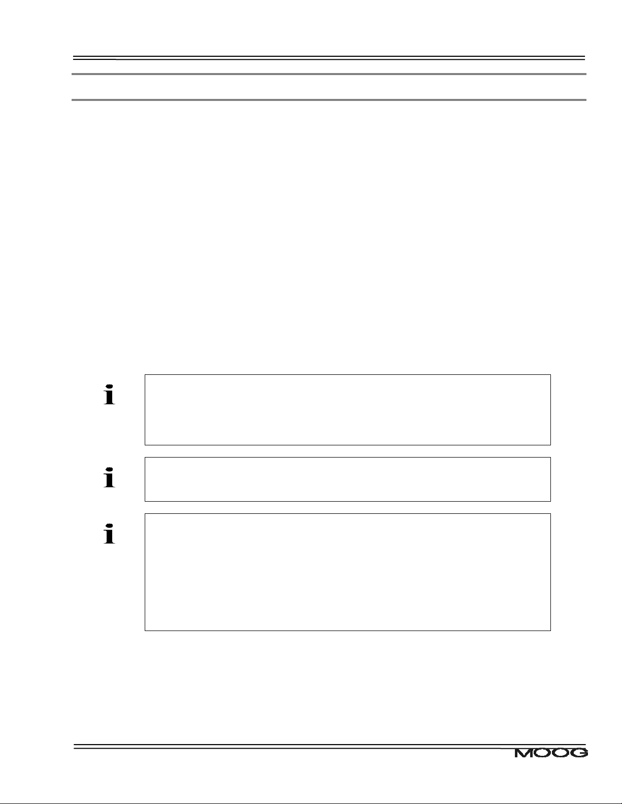
NOTE - These safety precautions are guidelines only and are not claimed to be
comprehensive. The Moog Brushless Technology products described herein, in
conjunction with the system controller, provide the capability for control of remote
devices. Typically, these remote devices move at high speeds and exert considerable
force. Like all mechanical systems and most industrial equipment, they must be treated
with respect by both the machine integrator and user, and the operator.
NOTE - This user’s guide defines “user” as the responsible person or company and
“operator” as a person who starts, stops or monitors workcell operation.
NOTE - This user’s guide should be read by all personnel who operate or who work
within or near the workcell.
Individuals responsible for the installation of the equipment described in this user’s guide
must ensure that only technically qualified service personnel are employed to work on
the installation.
In the context of these safety instructions, skilled technical personnel means people who
are familiar with the product, and have the necessary technical qualifications required for
the performance of their functions.
CDS7324 (FORMERLY LSF-0819)
Rev. A INSTALLATION & USER’S MANUAL
Page 18
CHAPTER 2.0 Safety & EMC Instructions 2-3
2.2.1 System Safeguards
a) General Safety Requirements
Users are required to implement safety measures with all equipment, systems and installations into which the
DS2110 Servo-drive are installed. In addition, safeguards must be an integral part of workcell design, installation,
operator training and operator procedures where this equipment is used.
Users are directed to refer to the European Union (EU) Machine Safety
Directive: 98/37/EC and EU Low Voltage Directive 73/23/EEC (as amended by
EU Directive 93/68/EEC) for essential health and safety requirements to be
Required for
CE-Compliance
met. Furthermore the requirements of the EU EMC Directive: 89/336/EEC (as
amended by EU Directive 92/31/EEC and 93/68/EEC) must be met by all
equipment, systems and installations into which the DS2110 Controllers are
installed.
Users are recommended to refer to the latest publications of the European
Union (EU) Commission and to local regulations for further information on the
requirements of these Directives of the EU.
Users are required to ensure that the drive is only connected to supply network
configurations of the following types
• TN Systems including TN-C, TN-S, TN-C-S
• TT Systems.
Required for
CE-Compliance
Connection to IT systems or corner-earthed TN systems is not allowed. Users
should ensure the nature of the supply system is appropriate before connecting
and operating the drive.
b) Specific Safety Requirements
The specific safety measures described below are required to be installed by the user into all equipment, systems
and installations into which the DS2110 Series Controllers are installed.
The user is required to provide safety interlocks to prevent unexpected restart during servicing of the DS2110
Controller and any equipment attached to or driven by these units.
The DS2110 Servo-drives themselves must be installed in enclosures or cabinets that provide a degree of ingress
protection against liquids and objects of at least IP54. These enclosures or cabinets must be accessible to
technically qualified service or maintenance persons only. All external Regen (Regenerative circuit) resistors used
with the DS2110 must be installed in enclosures which provide a degree of ingress protection against liquids and
objects of at least IP22 and which are accessible to technically qualified service or maintenance persons only.
Protection against electric shock must be maintained when installing these resistors.
The equipment may have a continuous leakage current of more than 3.5 mA A.C. or 10 mA D.C. in normal use.
The DS2110 must be permanently and reliably connected to Earth and all conductive parts in the IP54 rated
enclosure or cabinet must be permanently connected to Earth. The impedance between the earth terminal and
any accessible part of the enclosure or cabinet should be less than or equal to 0.1ohm.
A D.C component can occur in the fault current in the event of a fault connection to earth. Only a residual-currentoperated protective device (RCD) of Type B is allowed. When the protection in installations with regard to indirect
contact is achieved by means of an RCD, their appropriate function/combination shall be verified.
All electrical supply wires and cables to this equipment must be installed in wireways (cable routings) which are
smooth and free from sharp edges.
CDS7324 (FORMERLY LSF-0819)
Rev. A INSTALLATION & USER’S MANUAL
Page 19
CHAPTER 2.0 Safety & EMC Instructions 2-4
Required for
CE-Compl iance
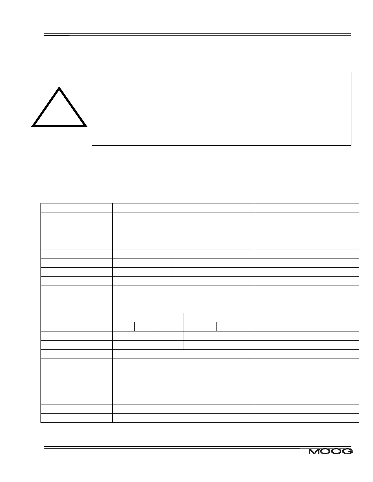
As no fuses are provided inside the drive, the DS2110 must be provided with suitable fusing to protect the drive.
The fuses required for each DS2110 model are detailed in the following table It is recommended to use UL
certified fuses and fuse blocks
DS2110 Models
Size 3/9 6/22
Short Circuit Rating 5,000 Amps
Power Line Fuse 25A, 660V FWP25-A1F Semiconductor (Cooper Bussmann)
Recovery Resistor Fuse Contact Moog Application Engineering for Advice
24Vdc Aux. Pwr. Fuse 3A, 250V Delayed
DS2110 Models Size A Size B Notes
Size 8/22 10/42 14/42
Short Circuit Rating 5,000 Amps
Power Line Fuse 50-FE 690V Semiconductor (Cooper Bussmann)
Recovery Resistor Fuse Contact Moog Application Engineering for Advice
24Vdc Aux. Pwr. Fuse 3A, 250V Delayed
DS2110 Models Size C Size D Notes
Size 20/45 25/70 30/90 50/140 60/180
Short Circuit Rating 5,000 Amps
Power Line Fuse 100-FE 690V 160-FEE 690V Semiconduct or (Cooper Bussmann)
Recovery Resistor Fuse Contact Moog Application Engineering for Advice
24Vdc Aux. Pwr. Fuse 3A, 250V Delayed
DS2110 Models Size E Notes
Size 100/240
Short Circuit Rating 10,000 Amps
Power Line Fuse 315-FM Semiconductor (Cooper Bussmann)
Recovery Resistor Fuse Contact Moog Application Engineering for Advice
24Vdc Aux. Pwr. Fuse 3A, 250V Delayed
All external d.c. supply voltages used with the DS2110 Series Controllers must be derived from a Safety Extra
Low Voltage (SELV) supply as defined by standard EN60950. Such SELV voltages do not exceed a value of 60
Vd.c. or 42.4 Va.c. peak under normal conditions and are supplied by circuits which are separated from all
hazardous voltage conductors by permitted safety methods such as reinforced insulation.
All external electrical wiring connected to this equipment must be colour coded in accordance with European
Standard EN 60204-1 requirements.
All wires and cables entering and leaving the IP54 rated enclosures or cabinets containing the DS2110 Controllers
and Regen resistor(s) must be protected and anchored in accordance with the requirements of EN 60204-1.
Size μA
Notes
rms
rms
10,000 Amps
rms
rms
rms
Table 1 - Recommended DS2110 Fusing
CDS7324 (FORMERLY LSF-0819)
Rev. A INSTALLATION & USER’S MANUAL
Page 20

CHAPTER 2.0 Safety & EMC Instructions 2-5
2.2.2 Equipment Safety
All persons must observe sound safety practices during the operation and testing of all electrically powered
equipment.
Prior to first use, power should not be applied to the DS2110 Servo-drive until all instructions in the Wiring and
Installation section of this User’s manual have been carried out.
WARNING – In the event of a fuse failure, remove all power, refrain from working on the unit for at least 5minutes
for the A size (6 minutes for the A-E sizes) to allow all internal voltages to decay to a safe level. Remove all fuses
from the system. Determine the source of the failure before re-commencing operation of the drive.
WARNING - DO NOT remove or replace any assemblies, subassemblies or components with primary
power present.
WARNING - Lethal voltages remain present within this equipment when the mains power is removed.
It is recommended to refrain from commencing any servicing, maintenance, repair or upgrading of
this equipment until at least 5 minute for the A size (6 minutes for the A-E sizes) after power
shutdown. It is further recommended to measure the voltage level at all high voltage terminals before
commencing any such activities, to ensure that no lethal voltages are present.
WARNING – The removable plug-in connectors of the DS2110 Servo-Drives are for ease of wiring
installation. These removable plug-in connectors are not suitable for connection or disconnection
under power. All connections must be made with power removed.
WARNING - Repair or internal adjustments to the DS2110 Series Controllers must not be attempted.
All faulty items must be returned to Moog Service Centers for maintenance and repair.
WARNING - Entering the workcell when HIGH POWER or PROGRAM RUNNING indicators are
ON may result in severe injury.
WARNING - The equipment described in this user’s guide operates at voltage levels, which can
exceed 800 volts D.C., and/or 460 volts A.C. These levels are a potential source of severe electrical
shock. DO NOT remove or replace any assemblies, subassemblies or components with the primary
power present. To avoid possible personal injury or equipment damage, always remove power
BEFORE attempting repair or upgrade procedures. Wait at least 5 minutes for the A size (6 minutes
for the A-E sizes) after power shutdown to ensure power supply capacitors have discharged. Then
using a voltmeter, check for safe levels across all high voltage power terminals.
CDS7324 (FORMERLY LSF-0819)
Rev. A INSTALLATION & USER’S MANUAL
Page 21
CHAPTER 2.0 Safety & EMC Instructions 2-6
Safeguards should be an integral part of a work cell design, installation, operator training, and operator
procedures. A computer-controlled system may activate remote devices under program control at times not
anticipated by personnel. It is critical that safeguards be in place to prevent personnel from entering the work cell
whenever equipment power is present. Moog highly recommends the use of work cell safety features such as
light curtains, safety gates or safety floor mats to prevent access to the workcell while power is present.
Computer controlled systems have various communication features which may aid the user in constructing
system safeguards, including:
• emergency stop circuitry
• binary input and output lines
• spare system-controlled user lines
The emergency power-off circuitry of a computer-controlled system is generally capable of switching external
power systems, as well as detecting intrusion signals from safety barriers.
All personnel must observe sound safety practices during the operation and testing of all electrically powered
equipment. To avoid injury or damage to equipment, always remove power BEFORE attempting ANY repair or
upgrade activity.
2.2.3 Safety Requirements for Cables
a) Requirements - Conductors and Cables
All cables and conductors used shall be specified as compliant with the requirements of European Standard EN
60204-1 and other known National and International Standards for the environment in which they are installed
and for the voltage and current carried.
Conductors and cables shall be specified and selected so as to be suitable for the operating conditions (e.g.
voltage, current, protection against electric shock, grouping of cables) and external influences (e.g. ambient
temperature, presence of water or corrosive substances, mechanical stress) which can exist.
Required for
CE-Compliance
User's whose machine installations require CECompliance should read this Section.
CDS7324 (FORMERLY LSF-0819)
Rev. A INSTALLATION & USER’S MANUAL
Page 22
CHAPTER 2.0 Safety & EMC Instructions 2-7
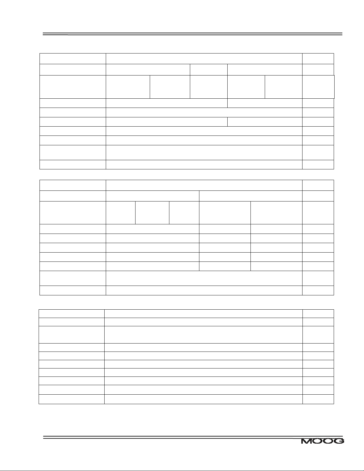
The following table details the recommended cable dimensions for all DS2110 models
Cable 3/9
AWG
(mm
Line Power 3x14 (2.1) 3x12 (3.3)
Protective Bonding Cable 1x 6 (13)
Motor Power Cable 4x14 (2.1) 4x12 (3.31) Shielded
Regen Resistor Cable 2x14 (2.1) Shielded
DC Bus Cable 2x14 (2.1) Shielded
Safety Interlock (If
applicable)
24V Power Cable 2x14 (2.1) Shielded
µA A B
6/22
2
)
AWG
(mm
DS2110 Models Notes
8/22
2
)
AWG
2
(mm
)
2x22 (0.3) Shielded
10/42
AWG (mm2)
14/42
AWG (mm2)
Note: 2x14 (2.08) = Number of conductors x conductor size (AWG = American wire gauge)
DS2110 Models Notes
Cable 20/45
AWG
2
(mm
)
Line Power 3x8 (8.4) 3x 6 (13) 3x 4 (21)
Protective Bonding Cable 1x 6 (13) 1x6 (13) 1x4 (21)
Motor Power Cable 4x8 (8.4) 4x6 (13) 4x4 (21) Shielded
Regen Resistor Cable 2x8 (8.4) 2x 6 (13) 2x4 (21) Shielded
DC Bus Cable 2x8 (8.4) 2x 6 (13) 2x4 (21) Shielded
Safety Interlock (If
applicable)
24V Power Cable 2x14 (2.1) Shielded
C D
25/70
AWG
2
(mm
30/90
AWG
2
)
(mm
)
2x22 (0.3) Shielded
50/140
AWG (mm2)
60/180
AWG (mm2)
Cable 100/240
Line Power 3 x 1 (42)
Protective Bonding Cable 1 x 1 (42)
Motor Power Cable 4 x 1 (42) Shielded
Regen Resistor Cable 2 x 2 (34) Shielded
DC Bus Cable 2 x 1 (42) Shielded
Safety Interlock (If applicable) 2x22 (0.3) Shielded
24V Power Cable 2 x 14 (2.1) Shielded
DS2110 Models Notes
E
AWG (mm2)
Table 2 - DS2110 Cable Dimensions
CDS7324 (FORMERLY LSF-0819)
Rev. A INSTALLATION & USER’S MANUAL
Page 23

CHAPTER 2.0 Safety & EMC Instructions 2-8
Wherever possible, insulated conductors and cables that have flame-retardant properties shall be used.
Where insulated conductors and cables can constitute a fire hazard due to the propagation of a fire or the
emission of toxic or corrosive fumes (e.g. PVC), guidance from the cable supplier should be sought. In particular it
is important to maintain the integrity of circuits having a safety function (e.g. emergency stop) for as long as
possible under these conditions.
The mechanical strength and thickness of the insulation shall be such that the insulation cannot be damaged in
operation or during laying, especially for cables pulled into ducts.
The voltage drops on cables and conductors shall not exceed 5% of the nominal voltage. The current carrying
capacity of the conductors and cables is determined by both:
• the maximum allowable conductor temperature under the highest possible steady state current under normal
conditions; and
• the ultimate allowable short-time conductor temperature under short circuit conditions.
b) Wiring Practices - Connections and routing
All connections, especially those of the protective bonding circuit, shall be secured against accidental loosening.
c) Wiring Practices - Conductor and cable runs
Conductors and cables shall be run from terminal to terminal without splices or intervening j oints
Where it is necessary to connect and disconnect cables and cable assemblies, sufficient extra length shall be
provided for this purpose.
The terminations of multicore cables shall be adequately supported where undue strain can be exerted on the
terminations of the conductors.
Wherever possible, the protective conductor shall be placed close to the associated live conductors in order to
decrease the impedance of the loop.
d) Wiring Practices - Conductors of different circuits
Subject to the constraints for EMC suppression given in this User’s manual, conductors of different circuits may
be laid side by side. They may occupy the same duct (e.g. conduit, cable trunking system) and may be in the
same multicore cable, provided that the arrangement does not impair the proper functioning of the respective
circuits. Where these circuits operate at different voltages, the conductors shall be either separated by suitable
barriers or insulated for the highest voltage to which any conductor within the same duct can be subjected.
Circuits which are not switched off by the supply disconnecting device (circuit breaker) shall be either physically
separated from other wiring or distinguished by color (or both) so that they can be identified as being live when
the supply disconnecting device is in the OFF or OPEN position.
e) Wiring Practices - Identification of conductors
For safety reasons, the color Green or the color Yellow shall not be used where there is a possibility of confusion
with the bicolor combination GREEN-AND-YELLOW.
Color identification using combinations of colors may be used provided there can be no confusion and that
GREEN or YELLOW is not used, except in the bicolor combination GREEN- AND-YELLOW.
CDS7324 (FORMERLY LSF-0819)
Rev. A INSTALLATION & USER’S MANUAL
Page 24

CHAPTER 2.0 Safety & EMC Instructions 2-9
f) Wiring Practices - Identification of the protective conductor
The protective conductor shall be readily distinguishable by shape, location, marking or color. When identification
is by color alone, the bicolor combination GREEN-AND-YELLOW shall be used throughout the length of the
conductor. This color identification is strictly reserved for the protective conductor.
For insulated conductors, the bicolor combination GREEN-AND-YELLOW shall be such that on any 15mm length,
one of the colors covers at least 30% and not more than 70% of the surface of the conductor, the other color
covering the remainder of the surface.
Where the protective conductor can be easily identified by its shape, position or construction (e.g. braided
conductor), or where the insulated conductor is not readily accessible, color coding throughout its length is not
necessary. However, the ends or accessible positions shall be clearly identified by the graphical symbol or by the
bicolor combination GREEN-AND-YELLOW.
g) Wiring Practices - Identification of the neutral conductor
Where a circuit includes a neutral conductor identified by color, the color shall be LIGHT BLUE. LIGHT BLUE
shall not be used for identifying any other conductor where confusion is possible.
In the absence of a neutral conductor, a LIGHT BLUE conductor may be used for other purposes except for use
as a protective conductor.
Where identification by color is used, bare conductors used as neutral conductors shall be either colored by a
LIGHT BLUE stripe, 15 mm to 100 mm wide, in each compartment or unit or at each accessible position, or
colored LIGHT BLUE throughout their length.
h) Wiring Practices - Wiring inside enclosures
Panel conductors shall be supported where necessary to keep them in place. Non-metallic channels or conduits
shall be permitted only when made with a flame-retardant insulating material. Where possible earthed shielded
metal cable ducting should be used to minimise EMC noise coupling.
It is recommended that electrical equipment mounted inside the enclosures be designed and constructed in such
a way as to permit modification of the wiring from the front of the enclosure. Where this is not possible and control
devices are connected from the rear of the enclosure, access doors or swing-out panels shall be provid ed.
Connections to devices mounted on doors or to other movable parts shall be made using flexible conductors in
accordance with European standard EN 60204-1, to allow for the frequent movement of the part. The conductors
shall be anchored to the fixed part and the movable part independently of the electrical connections.
Conductors and cables that do not run in ducts shall be adequately supported.
Terminal blocks or attachment plug/socket combinations shall be used for control wiring that extends beyond the
enclosure.
Power cables and cables of measuring circuits may be directly connected to the terminals of the devices for which
the connections were intended.
i) Wiring Practices - Wiring outside enclosures
The means of introduction of cables or ducts with their individual glands, bushings, etc., into an enclosure shall
ensure that the degree of protection is not reduced.
Conductors and their connections external to the electrical equipment IP54 enclosures shall be installed in
suitable ducts (i.e. conduit or cable trunking systems) as described in Section 2.2.4, except for suitably protected
cables, which may be installed without enclosing ducts and with or without the use of open cable trays or cable
support means.
Fittings used with ducts or multi-conductor cable shall be suitable for the physical environ ment.
CDS7324 (FORMERLY LSF-0819)
Rev. A INSTALLATION & USER’S MANUAL
Page 25

CHAPTER 2.0 Safety & EMC Instructions 2-10
Flexible conduit or flexible multi-conductor cable shall be used where it is necessary to employ flexible
connections to pendant push-button stations. The weight of pendant stations shall be supported by means other
than the flexible conduit or the flexible multi-conductor cable, except where the conduit or cable is specifically
designed for that purpose.
Flexible conduit or flexible multi-conductor cable shall be used for connections involving small or infrequent
movements. They shall also be permitted to complete the connection to normally stationary motors, to position
switches, and to other externally mounted devices.
Connections to frequently moving parts shall be made with conductors suitable for flexing service in accordance
with European standard EN 60204-1. Flexible cable and flexible conduit shall be so installed as to avoid
excessive flexing and straining particularly at the fittings.
Cables subject to movement shall be supported in such a way that there is no mechanical strain on the
connection points nor any sharp bending. The loop shall have sufficient length to provide for a bending radius of
the cable of at least ten times its outside diameter.
Where cables subject to movement are close to moving parts, precautions shall be taken so that a space of at
least 25mm shall be maintained between the moving parts and the cables. Where this distance is not practicable,
fixed barriers shall be provided between the cables and the moving parts.
The cable sheath shall be resistant to the normal wear which can be expected from movement, and to the effects
of atmospheric contaminants (e.g. oil, water, coolants, dust).
Where flexible conduit is adjacent to moving parts, the construction and supporting means shall prevent damage
to the flexible conduit or cable under all conditions of operation.
Flexible metal conduit shall not be used for rapid or frequent movements, except when specifically designed for
that purpose.
j) Wiring Practices - Ducts, connection and junction boxes
All sharp edges, flash, burrs, rough surfaces, or threads, with which the insulation of the conductors may come in
contact, shall be removed from ducts and fittings. Where necessary, additional protection consisting of a flameretardant, oil-resistant insulating material shall be provided to protect conductor insulatio n.
Ducts and cable trays shall be rigidly supported and positioned at a sufficient distance from the moving parts and
in such a manner so as to minimise the possibility of damage or wear.
Cable trunking systems external to enclosures shall be rigidly supported and clear of all moving or contaminating
portions of the machine or equipment into which they are installed.
CDS7324 (FORMERLY LSF-0819)
Rev. A INSTALLATION & USER’S MANUAL
Page 26
CHAPTER 2.0 Safety & EMC Instructions 2-11
2.2.4 EMC requirements for cables
Avoid close parallel routing of signal cables and power cables. Always use the minimum length of cable
necessary and install all cables in a fixed routing.
Data signal cables, motor power and resolver/signal cables, regen resistor cables and power input cables shall
have segregated routings. Where cable routings must intersect, it is recommended that they intersect at an angle
of 90 degrees, to minimise EMC noise coupling.
Required for
CE-Compliance
User's whose machine installations require for
CE-Compliance should read this Section.
Where signal and power cables must run in parallel it is recommended that these cables are separated by at least
20 cm. Where possible cables shall be routed in earthed shielded cable ducting, to minimise electromagnetic
noise coupling.
Use shielded cable to connect the external regen resistor (if installed) to the DS2110. The length of this cable
shall be as short as possible. The shields of these voltage supply cables shall be earthed to Chassis Earth using
the EMC kit or the panel earth bar. Alternatively, if the cable is required to pass through an enclosure panel
earthed to Chassis Earth, the shield may be earthed to the panel by use of a 360 degree metal cable gland.
Cables supplying external d.c. supply voltages to the DS2110 Servo-drive (For example, the 24 Vd.c. supply)
must be as short as possible. The supply wires shall be twisted together or alternatively shielded cable shall be
used.
Cables connecting the d.c. bus from the DS2110 Servo-drives must be as short as possible. Shielded cable shall
be used.
Motor power cables must be shielded with the cable shield securely connected to Chassis Earth at both ends of
the cable. At the DS2110 end of the cable the shield shall be earthed to Chassis Earth using the EMC kit or the
panel earth bar.
Motor resolver/signal cables must be sh ielded with the cable shield securely connected to Chassis Earth at both
ends of the cable.
Signal cables must be shielded with the cable shield securely connected to make a good HF earth bond to
Chassis Earth at both ends of the cable.
CDS7324 (FORMERLY LSF-0819)
Rev. A INSTALLATION & USER’S MANUAL
Page 27
CHAPTER 2.0 Safety & EMC Instructions 2-12
2.3 Electromagnetic Compatibility (EMC)
The DS2110 Servo-drive are system components which must be installed in a correct manner to ensure that all
electromagnetic compatibility (EMC) requirements are met. The requirements of European Union (EU) EMC
Directive: 89/336/EEC (as amended by EU Directives 92/31/EEC and 93/68/EEC ) must be met by all equipment,
systems and installations into which the DS2110 Servo-drive are installed.
Required for
CE-Compliance
User's whose machine installations are intended for
CE-Compliance should read this Section.
For further information on the requirements of EU EMC Directive the user is recommended to refer to the latest
publications of the EU Commission and to local regulations.
The DS2110 Servo-drive have been tested for compliance with the requirements of the EU EMC Directive in so
far as they can be regarded as single functional units. The DS2110 have been tested in typical configurations and
it has been found that these configurations meet the essential requirements of the EU EMC Directive. The EMC
standards applied is EN61800-3:
This standard is published by CENELEC, the European Committee for Electrotechnical Standardisation,
Brussels.
2.3.1 Specific Electromagnetic Compatibility (EMC) Requirements:
The EMC measures outlined below are required to be installed by the user into all equipment, systems and
installations into which the DS2110 is installed. Further details are given throughout this User’s Guide.
The DS2110 Servo-drive must be installed by mounting on a panel in a manner that ensures that EMC earthing
requirements are met. (Refer Section 3 of this User’s Guide).
EMC brackets are provided to facilitate earthing of cable shields prior to entering the DS2110. Cable shields must
be bonded to either the panel earthing bar or the EMC brackets.
For safety reasons the DS2110 Servo-drive, and the panel on which they are mounted must be installed in
enclosures or cabinets which provide a degree of ingress protection against liquids and objects of at least IP54.
These enclosures or cabinets must be accessible to technically qualified service or maintenance persons only.
For Electrostatic Discharge (ESD) reasons all service or maintenance persons must ground themselves to the
chassis of the equipment when performing service functions inside the IP54 rated enclosure or cabinet in which
the DS2110 Servo-drive are installed.
All external d.c. supply voltages used with the DS2110 must be supplied from power supplies which are compliant
with the requirements of the EU EMC Directive. All other equipment that is connected to the DS2110 must be
compliant with the EU EMC Directive.
CDS7324 (FORMERLY LSF-0819)
Rev. A INSTALLATION & USER’S MANUAL
Page 28
CHAPTER 2.0 Safety & EMC Instructions 2-13
Shielded cable is required to be installed by the user for many external user cable connections to the DS2110.
Details of areas where shielded cable must be installed and details of earthing arrangements which must be
implemented for the shields of such cables are given throughout Section 3 of this User’s Guide.
This equipment intended to be connected to an industrial low-voltage power supply network, or public network,
which does not supply buildings used for domestic purposes (second environment, according to EMC Standards).
If connected to a low-voltage public network that supplies domestic premises (first environment), this product is
expected to cause radio interference in which case supplementary measures may be required.
2.3.2 Recommended EMC Filters
No internal filtering is provided in the DS2110. To ensure EMC compliance an external line filter must be installed.
The recommended filters for the DS2110 are detailed below.
DS2110 µA Size
Moog
Order Code
- Schaffner Fairite Clamp.
Manufacturer Rated Current
Max Voltage Drive Input
(A)
o
@ 50
C (40oC)
- -
Part # 00443164151
Input
24V
dc
(4 Turns in Common Mode)
AT6009 Schaffner FN 258-7/07 7 (8.4) 3x480V 3-phase AC Line Input
- Schaffner FN 350-12/29 12 (13.8) 1x250V
1-phase AC Line Input
(µA 3/11 only)
DS2110 A,B,C,D, E Sizes
Moog
Order Code
Manufacturer Rated Current
Max Voltage Drive Input\Size
(A)
o
@ 50
C (40oC)
AT60171 Schaffner FN2070-3-06 (3) 250V 24Vdc Input
AT6009 Schaffner FN258-7/07 7 (8.4) 3x480V
AT6010 Schaffner FN258-16/07 16 (19.2) 3x480V
3-phase AC Line Input
(Size A)
3-phase AC Line Input
(Size B)
AT6011 Schaffner FN258-30/07 30 (36) 3x480V 3-phase AC Line Input
(Size C)
AT6012 Schaffner FN258-42/07 42 (50.4) 3x480V
AT6013 Schaffner FN258-55/07 55 (66) 3x480V
AT6015 Schaffner FN258-100/35 100 (113) 3x480V
3-phase AC Line Input
(Size D 50/140)
3-phase AC Line Input
(Size D 60/180)
3-phase AC Line Input
(Size D 100/300)
Table 3 - Recommended EMC Filters for DS2110
1
The 24Vdc filter can be used with two DS2110 drives. If more than two DS2110 drives are in use on a machine, a filter
from the same series can be used with a higher current rating.
CDS7324 (FORMERLY LSF-0819)
Rev. A INSTALLATION & USER’S MANUAL
Page 29
7
CHAPTER 2.0 Safety & EMC Instructions 2-14
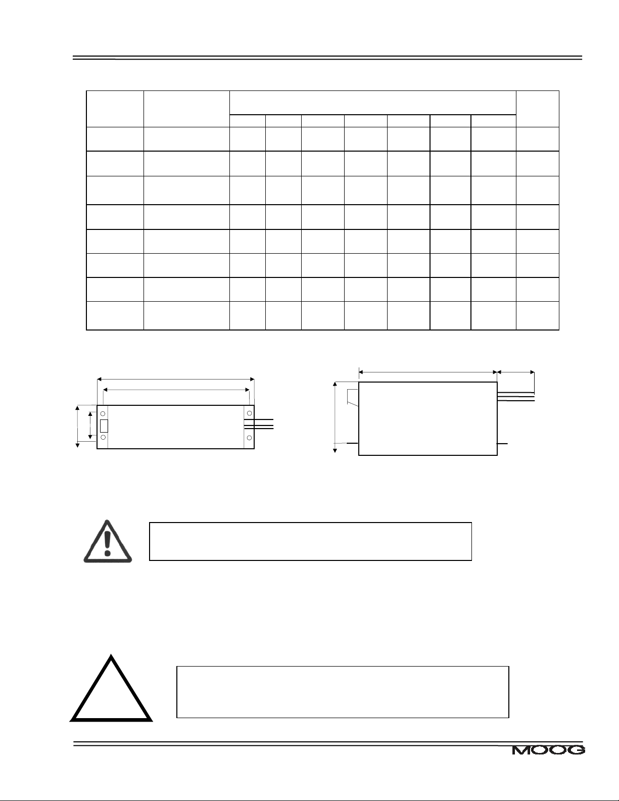
The following table details the mechanical dimensions of the recommended filters.
Moog
Order
Code
AT6017
AT6009
-
AT6010
AT6011
AT6012
AT6013
AT6015
Manufacturer Dimensions
[mm]
Schaffner
FN2070-3-06
Schaffner
FN 258-7/07
Schaffner
FN350-12/29
Schaffner
FN258-16/07
Schaffner
FN258-30/07
Schaffner
FN258-42/07
Schaffner
FN258-55/07
Schaffner
FN258-100/35
L1 L2 L3 L4 L5 L6 L7 [kg]
85 75 54 0 65 40.3 Fast-on 0.25
255 240 50 25
225
±0.8
126
±0.8
99.5 51 105 95 99.5 57
3.5 290 55 30
275±0.8 142±0.
335 320 60 35 305 150 400 1.8
329 314 70 45 300 185 500 2.8
329 314 80 55 300 185 500 3.1
379 364 90 65 350 220
TOP VIEW SIDE VIEW
L1
L2
L5
L4 L3
L6
8
Weight
300 1.1
Terminal
blocks
only
0.9
300 1.7
Terminal
blocks
only
5.5
L
Table 4 - DS2110 Recommended Filters Mechanical Sizing
Caution: A space of at least 60mm (2.4”) must be left around the filter for
air circulation when the cabinet does not have forced ventilation.
The filter must be located as close as possible to the drive input. If the separation between filter and drive
exceeds 30 cm (1’) , then a flat cable (multi-thread copper flat cable) should be used for the RF connection
between filter and drive.
Before mounting the drive and the filter to the cabinet, check that the panel
surface is conductive. If not, remove any paint and/or other insulating
Required for
CE-Comp liance
material before mounting the drive and filter.
CDS7324 (FORMERLY LSF-0819)
Rev. A INSTALLATION & USER’S MANUAL
Page 30
CHAPTER 2.0 Safety & EMC Instructions 2-15
EMC filter can produce high leakage currents to ground (Protective Earth). The current levels associated with
individual filters are detailed in the associated filter datasheet.
CAUTION: The filter must be connected to earth before connecting
the supply.
2.3.3 EMC requirements for cables
Requi red for
CE-Compl i ance
User's whose machine installations require for CECompliance should read this Section .
Avoid close parallel routing of signal cables and power cables. Always use the minimum length of cable
necessary and install all cables in a fixed routing.
Data signal cables, motor power and resolver/signal cables, regen resistor cables and power input cables shall
have segregated routings. Where cable routings must intersect, it is recommended that they intersect at an angle
of 90 degrees, to minimise EMC noise coupling.
Where signal and power cables must run in parallel it is recommended that these cables are separated by at least
20 cm. Where possible cables shall be routed in earthed shielded cable ducting, to minimise electromagnetic
noise coupling.
Use shielded cable to connect the external regen resistor (if installed) to the DS2110. The length of this cable
shall be as short as possible. The shields of these voltage supply cables shall be earthed to Chassis Earth using
the EMC kit or the panel earth bar. Alternatively, if the cable is required to pass through an enclosure panel
earthed to Chassis Earth, the shield may be earthed to the panel by use of a 360 degree metal cable gland. If this
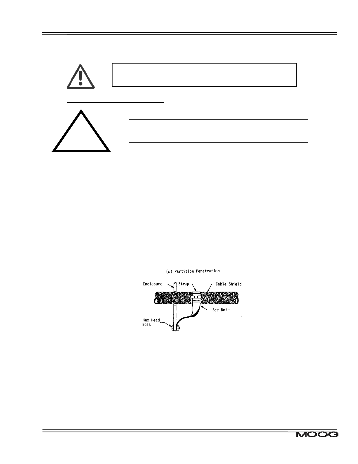
is not possible, a copper strap of minimum length should be used. See Figure 1 Partition Crossing.
Figure 1 Partition Crossing
All external Regen (Regenerative circuit) resistors used with the DS2110 must be installed in conductive
enclosures which provide a degree of ingress protection against liquids and objects of at least IP22. Any paint on
the panel or regen resistor enclosure must be removed before the regen resistor enclosure is mounted.
Cables supplying external d.c. supply voltages to the DS2110 Servo-drive (For example, the 24 V
supply) must
d.c.
be as short as possible. The supply wires shall be twisted together or alternatively shielded cable shall be used.
The 24 V
supply should be routed as far from the motor power cable as possible to ensu re EMC compliance.
d.c.
Cables connecting the d.c. bus from the DS2110 Servo-drives must be as short as possible. Shielded cable shall
be used.
CDS7324 (FORMERLY LSF-0819)
Rev. A INSTALLATION & USER’S MANUAL
Page 31

CHAPTER 2.0 Safety & EMC Instructions 2-16
Motor power cables MUST be shielded with the cable shield securely connected to Chassis Earth at both ends of
the cable. At the DS2110 end of the cable, the shield shall be earthed to Chassis Earth using the EMC kit or the
panel earth bar. The correct method to earth the shield is shown in Figure 2 Correct Cable Preparation Grounding
of Shield to Chassis.
Figure 2 - Correct Cable Preparation Grounding of Shield to Chassis
Motor resolver/signal cables must be sh ielded with the cable shield securely connected to Chassis Earth at both
ends of the cable.
Signal cables must be shielded with the cable shield securely connected to make a good HF earth bond to
Chassis Earth at both ends of the cable.
Typical cable shield terminations for each of the cables on each DS2110 size are shown in the following figures.
CDS7324 (FORMERLY LSF-0819)
Rev. A INSTALLATION & USER’S MANUAL
Page 32

CHAPTER 2.0 Safety & EMC Instructions 2-17
Figure 3 - DS2110 µA Cable Shield Terminations
CDS7324 (FORMERLY LSF-0819)
Rev. A INSTALLATION & USER’S MANUAL
Page 33

CHAPTER 2.0 Safety & EMC Instructions 2-18
Figure 4 - DS2110 A & B Cable Shield Terminations
CDS7324 (FORMERLY LSF-0819)
Rev. A INSTALLATION & USER’S MANUAL
Page 34

CHAPTER 2.0 Safety & EMC Instructions 2-19
Figure 5 - DS2110 C Cable Shield Terminations
CDS7324 (FORMERLY LSF-0819)
Rev. A INSTALLATION & USER’S MANUAL
Page 35

CHAPTER 2.0 Safety & EMC Instructions 2-20
Figure 6 - DS2110 D Cable Shield Terminations
CDS7324 (FORMERLY LSF-0819)
Rev. A INSTALLATION & USER’S MANUAL
Page 36

CHAPTER 2.0 Safety & EMC Instructions 2-21
Figure 7 - DS2110 E Cable Shield Terminations
CDS7324 (FORMERLY LSF-0819)
Rev. A INSTALLATION & USER’S MANUAL
Page 37

CHAPTER 2.0 Safety & EMC Instructions 2-22
2.4 UL Requirements
Detailed below are the specific UL requirements for the DS2110.
2.4.1 Specific UL Requirements
• Usage: The DS2110 shall be used according to the guidelines given in this manual.
• Ratings: The DS2110 shall be used within the ratings specified in the markings on the equipment.
• 24V Logic Supply: The 24V supply is intended for use in the secondary of a Class 2 supply. Alternatively, it
should be additionally fitted with a Listed current limiting fuse, rated 3A on the supply input to the device.
• Surrounding Air Temperature:- “Maximum Surrounding Air Temperature, 40
• Pollution Degree 2 Installation:- The drive must be installed in a Pollution Degree 2 environment.
• Equipment Designation: - Open Type Equipment.
• Short circuit Ratings:-
DS2110 3/9, 6/22, 8/22, 10/42, 14/42, 20/45, 25/70, 30/90, 50/140: “Equipment suitable for use on a
circuit capable of delivering not more than 5000 rms symmetrical Amperes, 460V ac + 10% Maximum”.
DS2110 60/180, 100/240: “Equipment suitable for use on a circuit capable of delivering not more than
10000 rms symmetrical Amperes, 460V ac + 10% Maximum”.
• Branch Circuit Protection. The Branch Circuit Protection for short circuit protection shall be provided in the
end use application by external fuses. Recommended fuses are manufactured by Cooper Bussmann.
DS2110 3/9 & 6/22: Fuse Model No. FWP-25A14F Semiconductor Type Fuses.
DS2110 8/22, 10/42, & 14/42: Fuse Model No. 50FE Semiconductor Type Fuses.
DS2110 20/45, 25/70 30/90: Fuse Model No: 100FE Semiconductor Type Fuses.
DS2110 50/140 & 60/180: Fuse Model No: 160FEE Semiconductor Type Fuses.
DS2110 100/240 : Fuse Model No: 315-FM Semiconductor Type Fuses.
• Wiring. The drive shall be wired with stranded and \ or solid copper (Cu), 60/75
tightening torque for terminal blocks specified in Section 3 of this manual shall be applied. These
requirements do not apply to the control circuit terminals.
• Regeneration Resistor. The regeneration resistor, when external, shall be wired with R/C (AVLV2) rated
wire or shall be insulated with R/C (YDPU2) or R/C (UZCW2) rated insulation.
• Field Wiring. The power connector of the DS2110 A (J6) is not rated as a Field Wiring Terminal. This
connector may only be used as a Factor Wiring Terminal block.
• Over-speed Protection: The DS2110 incorporates a software-based over-speed protection. See ‘Motor
Rating Parameters’ and ‘Velocity Limiting’ in Section 5 of this Manual.
• Motor Overload Protection: The DS2110 does not incorporate an internal motor load protection. The drive is
intended to be used with motors that have integral thermal protection in the form of an NTC or PTC
thermistor. The selections of NTC or PTC and overtemperature fault level are set in software. See ‘Motor
Thermal Parameters’ and ‘Motor Thermal Protection Mechanism’ in Section 5 of this manual.
• Overcurrent Protection: The DS2110 is equipped with internal over current protection. See the ‘Cabling and
Interconnect Protection Scheme’ detailed in Section 5 of this manual.
CDS7324 (FORMERLY LSF-0819)
Rev. A INSTALLATION & USER’S MANUAL
o
C”.
o
C conductors only. The
Page 38

CHAPTER 2.0 Safety & EMC Instructions 2-23
Page Intentionally Blank
CDS7324 (FORMERLY LSF-0819)
Rev. A INSTALLATION & USER’S MANUAL
Page 39

CHAPTER 3.0 Wiring and Installation 3-1
This chapter covers the installation, wiring and cabling of the Moog DS2110 Servo-drive series. A pictorial
diagram of a single-axis system, with typical components included, is shown in Figure 3.1. Users are directed to
read Chapter 2, Safety Instructions, before proceeding with wiring and installation.
WARNING - This equipment must be permanently and reliably connected to Earth and all conductive parts
in the IP54 rated enclosure in which the DS2110 Series Servo-drive is installed must be reliably connected
to Protective Earth. A Protective Earth connection must come directly from an approved AC mains
network. Stranded copper-wire is recommended to carry the earth.
3.1 System Components
The following components are required to build a Moog brushless motor digital control system (refer to Figure
3.1). The user supplies all components besides the DS2110, EMC-Brackets, motor and other accessory cabling.
3.1.1 A.C. Mains Power Interface
The DS2110 should be connected to a three-phase AC supply. Operation with a single-phase supply is only
allowed with the G362-x003 and G362-x006 variants of the drive. For single-phase operation, the phase supply
voltage must be limited to 230V and the input power to the drive limited to 1.1kW.
3.1.2 A.C. Input Line Protection
Details of the recommended Line fuses are given in Chapter 2 of this manual. Alternatively an AC mains Circuit
Breaker (Instantaneous Trip Type) can be used as a protective device providing its ratings are equivalent to the
recommended fuses.
After a power loss to the servo-drive, the motor will continue running until its stored energy is dissipated through
friction alone, or will be stopped by a motor-equipped brake if a brake is available.
It is also recommended to install a contactor rated for the DS2110 input between the line fuses and the EMC filter
at the input of the DS2110 (refer to Figure 3.1). This contactor should be controlled directly by user supplied
Emergency Stop Buttons and other series connected safety switches to remove AC input power in any situation
affecting personnel safety.
WARNING - The supply-disconnecting device (circuit breaker) must be switched to the OFF
position before any service or maintenance activity is commenced.
3.1.3 Line Filter Requirements
Details of the recommended line filters for each of the DS2110 variants are given in Chapter 2 of this manual.
CDS7324 (FORMERLY LSF-0819)
Rev. A INSTALLATION & USER’S MANUAL
Page 40

CHAPTER 3.0 Wiring and Installation 3-2
Figure 3.1Typical DS2110 System Components (µA Size)
CDS7324 (FORMERLY LSF-0819)
Rev. A INSTALLATION & USER’S MANUAL
Page 41

CHAPTER 3.0 Wiring and Installation 3-3
3.1.4 Serial Set-up Terminal (User-Supplied)
An RS-232 interface should be established for individual servo-drive communications, using a PC. The PC can
run Moog's WinDrive Windows-based user-interface program.
The personal computer using Windrive is a service engineering tool only and
must be installed so that use of the key sequences which allow control of the
machine functions is accessible to authorized, qualified service personnel only.
Required for
CE-Compliance
All such service set-up computers must be CE -marked as compliant with the
EU EMC Directive.
3.1.5 Control-Backup Power Input (User Supplied)
The DS2110 requires a control power source to supply backup-power for the control electronics. This controlbackup power is useful where the user requires that the DS2110 does not lose absolute position data or status
information when AC mains power is removed from the DS2110.
The user is directed to the local Moog sales office or authorised distributor for a recommended list of these control
power source devices.
The G362-x003 &-x006 MUST have a 24Vdc logic backup supply connected for
the drive to operate. No internal high voltage backup is provided on these
smaller models.
The 24V
control power option allows high voltage motor power to be removed from a DS2110 Series Servo-
dc
drive without losing control power.
The acceptable voltage range for this supply is 24V
±10% with a minimum current rating of 2Adc per DS2110
dc
Series Servo-drive connected. A low cost unregulated DC supply is adequate.
Required for
CE-Compliance
NOTE - The 24Vdc power supply must be compliant with the requirements of
the EU EMC Directive. The 24V
output from the power supply must be Safety
dc
Extra Low Voltage (SELV - as defined by European standard EN 60950).
3.1.6 Brushless Servo motors
The DS2110 series Servo-drive is compatible with Moog brushless servomotors.
Normal connection to the motor requires two cables - a power and a signal cable. The power cable provides
three-phase stator power, protective earth and brake connections. The signal cable carries position transducer
feedback signals and motor temperature detection connections.
CDS7324 (FORMERLY LSF-0819)
Rev. A INSTALLATION & USER’S MANUAL
Page 42

CHAPTER 3.0 Wiring and Installation 3-4
3.1.6.1 Brushless Motor Brake 24V Power Supply
The motor brake requires a 24V
rated currents of all brakes connected.
supply for release. This should be rated to cover at least twice the sums of the
dc
3.1.7 Heatsinks and Climatic Control
The need for air conditioning will depend on the duty cycle of the system and the surrounding ambient
temperature. The maximum allowable ambient temperature is 40°C (104°F). The humidity range is 5-95% noncondensing.
All DS2110 Servo-drives incorporate internal cooling fans and integral heat sinks. Other than controlling ambient
conditions, additional heat sinking is not required.
CDS7324 (FORMERLY LSF-0819)
Rev. A INSTALLATION & USER’S MANUAL
Page 43

CHAPTER 3.0 Wiring and Installation 3-5
3.2 Equipment Mounting
This section details the mechanical dimensions of the DS2110 chassis, as well as required clearances for cabling
etc. The DS2110 is designed to be panel or cabinet mounted. The DS2110 must be mounted in a vertical
orientation. The DS2110 must be panel mounted within an enclosure or cabinet that provides a degree of ingress
protection against liquids and objects of at least IP54. Such enclosures or cabinets must be accessible to
technically qualified service or maintenance persons only. It is recommended that the cabinet be ventilated using
filtered or conditioned air, free of corrosive or electrically conductive contaminants. The accumulation of dust, dirt,
etc. on the equipment must be avoided. A minimum clearance above and below each of the DS2110 drive sizes is
required. These distances are detailed in Table 3. -1.
DS2110 Size Minimum Clearance Top
(mm)
µA & A 60 100
B 60 100
C 80 160
D 100 200
E 200 300
Table 3. -1 Minimum Clearance around DS2110 Drives
If any of the DS2110 units are mounted in a closed cabinet, allow 100mm clearance at the front for cable bends.
Minimum Clearance
Bottom (mm)
CDS7324 (FORMERLY LSF-0819)
Rev. A INSTALLATION & USER’S MANUAL
Page 44

CHAPTER 3.0 Wiring and Installation 3-6
Figure 3.2 Typical DS2110 Cable Bend Radius Requirements
The DS2110 must be permanently and reliably connected to Earth and all conductive parts in the IP54 rated
enclosure or cabinet must be permanently connected to Earth. The impedance between the earth terminal and
any accessible part of the enclosure or cabinet should be less than or equal to 0.1 ohm.
Required for
CE-Compliance
NOTE - The DS2110 Series Servo-drives are system components that must be
installed in the correct manner to ensure that all electromagnetic compatibility (EMC)
requirements are met. (Refer to Chapter 2 of this User’s Guide).
The DS2110 must be mounted on a panel with a flat solid surface in a manner that
ensures that EMC earthing requirements are met.
There must be a clean flat conductive surface at all of the mounting points. Remove
paint or other insulating materials and provide conductive corrosion protection at the
mounting points. It is important that there is good high-frequency bonding between the
panel and the DS2110 Servo-drive. Conductive hex socket head bolts with conductive
locking washers should be used.
CDS7324 (FORMERLY LSF-0819)
Rev. A INSTALLATION & USER’S MANUAL
Page 45

CHAPTER 3.0 Wiring and Installation 3-7
Figure 3.3 DS2110 µA Mechanical & Mounting Dimensions
CDS7324 (FORMERLY LSF-0819)
Rev. A INSTALLATION & USER’S MANUAL
Page 46

CHAPTER 3.0 Wiring and Installation 3-8
Figure 3.4 DS2110 A Mechanical & Mounting Dimensions
CDS7324 (FORMERLY LSF-0819)
Rev. A INSTALLATION & USER’S MANUAL
Page 47

CHAPTER 3.0 Wiring and Installation 3-9
Figure 3.5 DS2110 B Mechanical & Mounting Dimensions
CDS7324 (FORMERLY LSF-0819)
Rev. A INSTALLATION & USER’S MANUAL
Page 48

CHAPTER 3.0 Wiring and Installation 3-10
Figure 3.6 DS2110 C Mechanical & Mounting Dimensions
CDS7324 (FORMERLY LSF-0819)
Rev. A INSTALLATION & USER’S MANUAL
Page 49

CHAPTER 3.0 Wiring and Installation 3-11
Figure 3.7 DS2110 D Mechanical & Mounting Dimensions
CDS7324 (FORMERLY LSF-0819)
Rev. A INSTALLATION & USER’S MANUAL
Page 50

CHAPTER 3.0 Wiring and Installation 3-12
Figure 3.8 DS2110 E Mechanical & Mounting Dimensions
CDS7324 (FORMERLY LSF-0819)
Rev. A INSTALLATION & USER’S MANUAL
Page 51

CHAPTER 3.0 Wiring and Installation 3-13
Page Intentionally Blank
CDS7324 (FORMERLY LSF-0819)
Rev. A INSTALLATION & USER’S MANUAL
Page 52

CHAPTER 3.0 Wiring and Installation 3-14
3.2.1 CE Items for Mechanical Installation
CE-Compliance
Required for
Additional electromagnetic compatibility (EMC) measures must be installed on
equipment associated with the DS2110 Servo-drive. The following measures must be
implemented:
• All external Regen (Regenerative circuit) resistors used with the DS2110 must
be installed in enclosures which provide a degree of ingress protection against
liquids and objects of at least IP22 and which are accessible to technically
qualified service or maintenance persons only. Protection against electric shock
must be maintained when installing these resistors.
• Use shielded cable to connect the external regen resistor (if installed) to the
DS2110 power supply. The length of this cable should be as short as possible.
The shields of these cables should be earthed to Chassis Earth using the
optional EMC Bracket kit or the panel earth bar. Alternatively, if the cable is
required to pass through an enclosure panel earthed to Chassis Earth, the shield
may be earthed to the panel by use of a 360 degree metal cable gland.
• Cables supplying external d.c. supply voltages to the DS2110 Series Servodrives (for example, the 24 Vd.c. supply) must be as short as possible. The
supply wires should be twisted together or alternatively shielded cable should be
used.
• Cables connecting the D.C. Bus from the DS2110 Power Supply to other
DS2110 Servo-drives must be as short as possible. The supply cables should be
shielded.
• Motor power cables must be shielded with the cable shield securely connected
to Chassis Earth at both ends of the cable. At the DS2110 Servo-drive end of the
cable, the shield should be earthed using the EMC Bracket.
• Motor feedback & signal cables must be shielded with the cable shield securely
connected to Chassis Earth at both ends of the cable.
• Signal cables must be shielded with the cable shield securely connected to make
a good HF earth bond to Chassis Earth at both ends of the cable.
Further details for the correct installation and shielding of cables and conductors are
given in Chapter 2.
CAUTION - Enclosure or cabinet temperature control is critical for performance,
reliability and life of electrical components. Maintaining a uniform temperature (check
for hot spots) within the specified values for the equipment will prevent premature
failure due to temperature stress.
CDS7324 (FORMERLY LSF-0819)
Rev. A INSTALLATION & USER’S MANUAL
Page 53

CHAPTER 3.0 Wiring and Installation 3-15
3.3 Dissipation
To calculate cabinet cooling requirements, Table 3. - 2 provides approximate equipment power dissipation values.
If the application employs regeneration, be sure to add the regen resistor power dissipation to the numbers
quoted in Table 3. - 2, (use the continuous wattage rating of the regen resistor if the actual application regen
dissipation is unknown).
Power Dissipation (@ nom. current)
DS2110 3Amp 6Amp 8Amp 10Amp 14Amp 20Amp 25Amp 30Amp 50Amp 60Amp 100Amp
(Watts)
60 90 110 120 180 250 300 400 650 800 1200
Table 3. - 2 Estimated Power Dissipation for the DS2110 Servo-drives
CDS7324 (FORMERLY LSF-0819)
Rev. A INSTALLATION & USER’S MANUAL
Page 54

CHAPTER 3.0 Wiring and Installation 3-16
3.4 DS2110 Connector Terminals
Figures 3.9 through 3.14 detail the connectors on the DS2110 (all sizes).
Figure 3.9 DS2110 Control Card Connector Terminals
CDS7324 (FORMERLY LSF-0819)
Rev. A INSTALLATION & USER’S MANUAL
Page 55

CHAPTER 3.0 Wiring and Installation 3-17
Figure 3.10 DS2110 Size µA Power Connector Terminals
Figure 3.11 DS2110 Size A & B Power Connector Terminals
CDS7324 (FORMERLY LSF-0819)
Rev. A INSTALLATION & USER’S MANUAL
Page 56

CHAPTER 3.0 Wiring and Installation 3-18
Figure 3.12 DS2110 Size C Power Connector Terminals
Figure 3.13 DS2110 Size D Power Connector Terminals
CDS7324 (FORMERLY LSF-0819)
Rev. A INSTALLATION & USER’S MANUAL
Page 57

CHAPTER 3.0 Wiring and Installation 3-19
Figure 3.14 DS2110 Size E Power Connector Terminals
CDS7324 (FORMERLY LSF-0819)
Rev. A INSTALLATION & USER’S MANUAL
Page 58

CHAPTER 3.0 Wiring and Installation 3-20
3.5 General System Wiring Guidelines
The following is a general reminder of the cable requirements for the DS2110 Series Servo-drives and related
equipment.
Size wire in accordance with standard wiring practice and local codes for amperage and wire length requirements.
Recommended wire sizes are given in Chapter 2.
NOTE - Cabling and component wiring is critical in obtaining successful operation of the system. Pay
close attention to specified wiring practice, cabling information, earthing and shielding requirements.
Improper wiring can result in electrical noise generation and unstable motor performance.
Avoid close parallel routing of signal wires and power wires, both inside and outside of the control cabinet. High
voltage bus wires should be shielded and their length should be minimised.
Ensure proper chassis earths on all equipment. Terminate all individual chassis earths from power supply and
servo-drives to a single tie point, (i.e. cabinet earth bus). Keep the distance from earth bus to earth ground as
short as possible. Similarly, keep distance from servo-drive and power supply chassis earths to the tie point as
short as possible. Chassis earth should be run close to D.C. Bus wires to minimise EMI. The impedance
between the earth terminal and any accessible part of the equipment enclosure or cabinet should be less than or
equal to 0.1 ohm
Tighten all terminal screws securely to avoid faulty operation. Torque screws to the specified values
All power connections to the DS2110 µA, A, B & C Series Servo-drives are through removable plug-in mating
connectors. Do not solder the ends of the cables to be inserted into screw clamp terminals. All power
connections to the DS2110 D & E are via screw terminal connections.
WARNING – The removable plug-in mating connectors are for ease of wiring and are not
suitable for connection or dis-connection when power is applied. All dis-connections must be
made with power removed.
WARNING - All electrical supply wires and cables to this equipment must be installed in conduits
(cable routings) which are smooth and free from sharp edges.
CAUTION - Shielded cable is required to be installed by the user for many external user cable
connections to the DS2110 Servo-drive. Details of areas where shielded cable must be installed
and details of earthing arrangements which must be implemented for the shields of such cables
are given in the relevant sections.
CDS7324 (FORMERLY LSF-0819)
Rev. A INSTALLATION & USER’S MANUAL
Page 59

q
g
CHAPTER 3.0 Wiring and Installation 3-21
Required for
CE-Compliance
CAUTION - All external electrical wiring connected to this equipment
must be color coded in accordance with European Standard EN
60204-1 re
CAUTION - Additional electromagnetic compatibility (EMC) measures
which must be installed on equipment cables associated with the
DS2110 Servo-drive are
CAUTION - All wires and cables entering and leaving the IP54 rated
enclosures or cabinets containing the DS2110 Servo-drive and the
Regen resistor(s) must be protected and anchored in accordance with
uirements.
iven in Chapter 2 of this User’s Guide.
-
3.5.1 Drive Contactor (User Supplied)
A contactor (suitably rated for the particular DS2110) should be installed just before the AC input line filter of the
DS2110. The contactor acts as a remote switch that may cut off the AC mains supply in the event of an
emergency shutdown. This contactor should be sized based on the continuous power of the system.
3.5.2 Wiring notes for J6, J7, J9 connectors (Size C)
The connectors used on the DS2110 Size C are formed using crimp terminals. The appropriate crimps (Molex
type 42815-0031) are supplied together the floating connectors for J6, J7, and J9. These crimps are sized for an 8
AWG (8.4 mm
(63814-0000, or 63811-1500, or equivalent). After crimping, the contact must be inserted into the floating
connector with the correct orientation and should be held in position by the TPA (Terminal Position Assurance)
jumper, as shown in Fig 3.15.
2
) cable with a 10 mm wire stripping. It is recommended to use the appropriate Molex crimping tool
Figure 3.15 DS2110 Size C Crimp Assembly
CDS7324 (FORMERLY LSF-0819)
Rev. A INSTALLATION & USER’S MANUAL
Page 60

CHAPTER 3.0 Wiring and Installation 3-22
3.6 Sequence of Component Wiring Recommendations
The following sequence for wiring is a recommendation. Individual wiring steps are denoted by a box character,
which can be used as an installation check off list.
The terminal block layout on all power supplies and servo-drives has been designed to isolate low voltage from
high voltage circuits. Cabinet conduits should be arranged to maintain this physical separation.
a) Power Circuit Wiring
Wire a 24V Logic Supply to the drive (Required on A size drives). Fit a suitable EMC filter on the 24V logic
Supply and fuse.
Wire a 24V Logic Supply to the drive for fan external supply, if necessary.
Wire a.c. mains input to user supplied fuses. Make a secure and reliable connection between the chassis of
the equipment and Earth.
Fit a suitable EMC Mains Line Filter after the User supplied fuses and contactor.
Wire a.c. mains from the user-supplied contactor to the power input poles of the DS2110.
b) Servo-drive Wiring
Plug in Axis I/O cable to J2 and connect other end to user I/O equipment.
Plug in resolver cable at J3 (or Encoder Cable to J4).
Connect appropriate communications cabling (RS232 at J1, and/or Field Bus).
c) Motor Wiring
Repeat the steps listed in this Section for each motor in the system.
Plug in and screw tight resolver/encoder cable to motor position connector.
Plug in and screw tight motor power cable to motor power connector. Also connect the brake terminations at
J2D (if provided).
Connect motor power cable to appropriate drive power terminals.
CDS7324 (FORMERLY LSF-0819)
Rev. A INSTALLATION & USER’S MANUAL
Page 61

CHAPTER 3.0 Wiring and Installation 3-23
3.7 Three-Phase A.C. Mains Power Source Configuration
The DS2110 may be supplied from a three-phase a.c. mains input. In this case the following user supplied
options are required:-
1. Three-Phase Mains Fusing
2. Mains Line Filter
3. 24Vd.c. Power Source & Fuse
4. 24V d.c. EMC Filter
Note that for DS2110 sizes A, B, C, D, & E, if the a.c. mains is still applied, and the control-backup power is
removed, then the DS2110 control section will still operate correctly. Control power can still be generated from
the high voltage D.C. Bus.
Figure 3.16 DS2110 Multi-Axis system with 3-Phase A.C. Mains Inputs
CDS7324 (FORMERLY LSF-0819)
Rev. A INSTALLATION & USER’S MANUAL
Page 62

μ
μ
CHAPTER 3.0 Wiring and Installation 3-24
3.7.1 AC Mains Power Source Connection
3.7.1.1 Size µA
a.c. Mains
L1
L2
L3
Protective
Earth
EMC Filter,
Fuses etc.
See
Section 2
Installation
4 5 6
L1 L2 L3
Connector J6
A
PE
Stud
4 5 6
L1 L2 L3
Connector J6
PE
Stud
A
Figure 3.17 µA AC Mains Input Connection
- Fixed connector: 12 pins, male connector
- Mating connector, 12 pins, female, supplied with the drive. Phoenix Combicon (Part # GMSTB 2.5/12-ST-
7.62)
- A size wiring: cable 14 AWG (2.1 mm
- PE Stud wiring: cable 6 AWG (13mm
2
- Tightening torque: 0.5Nm.
Pos. Name Function
J6.4 L1
J6.5 L2
J6.6 L3
PE PE Protective Earth Stud on Chassis
Table 3. -3 J6 AC Mains Power connector, µA Size
2
). Wire stripping: 7 mm.
)
Phase "L1", three-phase voltage input 230/460Vac ±10%
Phase "L2", ", three-phase voltage input 230/460Vac ±10%
Phase "L3", ", three-phase voltage input 230/460Vac ±10%
CDS7324 (FORMERLY LSF-0819)
Rev. A INSTALLATION & USER’S MANUAL
Page 63

Α
CHAPTER 3.0 Wiring and Installation 3-25
3.7.1.2 Size A & B
a.c. Mains
L1
L2
L3
Protective
Earth
EMC Filter,
Fuses etc.
See
Section 2
Installation
4 5 6
U1 V1 W1
Connector J6
PE
Stud
& Β
Figure 3.18 A & B AC Mains Input Connection
- Fixed connector: 12 pins, male connector
- Mating connector, 12 pins, female, supplied with the drive. Phoenix Contact (Part # 1767106)
2
- A size wiring: cable 14AWG (2.1 mm
- B size wiring: cable 12AWG (3.3 mm
- PE Stud wiring: cable 6 AWG (13mm
). Wire stripping: 7 mm
2
). Wire stripping: 7 mm
2
)
- Tightening torque: 0.5Nm.
Pos. Name Function
J6.4 U1
J6.5 V1
J6.6 W1
Phase "L1", three-phase voltage input 230/460Vac ±10%
Phase "L2", ", three-phase voltage input 230/460Vac ±10%
Phase "L3", ", three-phase voltage input 230/460Vac ±10%
PE PE Protective Earth Stud on Chassis
Table 3. -4 J6 AC Mains Power connector, A & B Size
CDS7324 (FORMERLY LSF-0819)
Rev. A INSTALLATION & USER’S MANUAL
Page 64

CHAPTER 3.0 Wiring and Installation 3-26
3.7.1.3 Size C
a.c. Mains
L1
L2
L3
Protective
Earth
EMC Filter,
Fuses etc.
See
Section 2
Installation
3 2 1
U1 V1 W1
Connector J6
PE
Stud
C
Figure 3.19 Size C AC Mains Input Connection
- Fixed connector: 5 pins, male connector
- Mating connector, 5 pins, female, crimped supplied with the drive. (Molex 42816-0512)
2
- C size wiring: cable 8 AWG (8.4 mm
- PE Stud wiring: cable 6 AWG (13mm
).
2
)
Pos. Name Function
J6.3 U1
J6.2 V1
J6.1 W1
Phase "L1", three-phase voltage input 230/460Vac ±10%
Phase "L2", ", three-phase voltage input 230/460Vac ±10%
Phase "L3", ", three-phase voltage input 230/460Vac ±10%
PE PE Protective Earth Stud on Chassis
Table 3. -5 J6 AC Mains Power connector, C Size
CDS7324 (FORMERLY LSF-0819)
Rev. A INSTALLATION & USER’S MANUAL
Page 65

CHAPTER 3.0 Wiring and Installation 3-27
3.7.1.4 Size D
a.c. Mains
L1
L2
L3
Protective
Earth
EMC Filter,
Fuses etc.
Section 2
Installation
Figure 3.20 Size D AC Mains Input Connection
- Fixed connector: 4 pole, screw terminal
2
- D size wiring: cable 6 AWG (13 mm
- D size wiring: cable 4 AWG ( 21mm
) for 50/140
2
) for 60/180
- PE Terminal wiring: cable 6 AWG (13 mm
- PE Terminal wiring: cable 4 AWG (21 mm
See
2
) for 50/140
2
) for 60/180
4 5 6
U1 V1 W1
Connector J9
D
PE
3
- Stripping Length 16mm
- Tightening Torque: 2-2.3Nm
Pos. Name Function
J9.3 PE Protective Earth Screw Terminal
J9.4 U1
J9.5 V1
J9.6 W1
Phase "L1", three-phase voltage input 230/460Vac ±10%
Phase "L2", ", three-phase voltage input 230/460Vac ±10%
Phase "L3", ", three-phase voltage input 230/460Vac ±10%
Table 3. -6 J9 AC Mains Power connector, D Size
CDS7324 (FORMERLY LSF-0819)
Rev. A INSTALLATION & USER’S MANUAL
Page 66

CHAPTER 3.0 Wiring and Installation 3-28
3.7.1.5 Size E
a.c. Mains
L1
L2
L3
Protective
Earth
EMC Filter,
Fuses etc.
Installation
Figure 3.21 Size E AC Mains Input Connection
- Fixed connector: 4 pole, screw terminal
2
- E size wiring: cable 1 AWG (42 mm
) for 310/300
- PE Terminal wiring: cable 1 AWG (42 mm
See
Section 2
2
) for 100/300
4 5 6
U1 V1 W1
Connector J9
E
PE
3
- Stripping Length 16mm
- Tightening Torque: 2-2.3Nm
Pos. Name Function
J9.3 PE Protective Earth Screw Terminal
J9.4 U1
J9.5 V1
J9.6 W1
Phase "L1", three-phase voltage input 230/460Vac ±10%
Phase "L2", ", three-phase voltage input 230/460Vac ±10%
Phase "L3", ", three-phase voltage input 230/460Vac ±10%
3.7.2 Softstart & Power Cycling Frequency Limits
The DS2110 contains an internal soft-start function. The soft-start function limits the inrush current into the
DS2110's D.C. Bus smoothing capacitors after the a.c. mains has been switched on.
If the frequency of power cycling becomes too high, then the power dissipation in the soft-start resistor can be
excessive. In this case the softstart circuitry may become damaged.
CAUTION:- The internal softstart resistors are designed to allow an AC application of once
every 60 seconds. If this rate is exceeded, then the internal softstart resistors may be damaged.
CDS7324 (FORMERLY LSF-0819)
Rev. A INSTALLATION & USER’S MANUAL
Page 67

μ
CHAPTER 3.0 Wiring and Installation 3-29
3.8 24V Backup Connection
The DS2110 is equipped with a 24V logic supply backup. This backup supply provides logic power to the drive
when AC mains power is removed.
For the µA size, this backup is mandatory for drive operation.
3.8.1 Size µA 24V Input Connection
24V Auxiliary
Supply
+24V
GND (0V)
Fuse
Fairrite Clamp Core
p/n # 00443164151
(4-Turns of Supply
cable)
Figure 3.22 Size µA 24V DC Input Connection
- Fixed connector: 12 pins, male connector
11 12
Connector J6
DS
11 12
Connector J6
μ
DS
- Mating connector, 12 pins, female, supplied with the drive. Phoenix Combicon (Part # GMSTB 2.5/12-ST-
7.62)
2
- A size wiring: cable 14 AWG (2.1 mm
).
- Stripping Length 7mm
- Tightening torque: 0.5Nm.
Pos. Name Function
J6.11 24V +24V Logic Backup Supply
J6.12 0V Logic Supply Return (Tied Internally to PE )
Table 3. -7 J6 24V Logic Power connector, µA Size
CDS7324 (FORMERLY LSF-0819)
Rev. A INSTALLATION & USER’S MANUAL
Page 68

CHAPTER 3.0 Wiring and Installation 3-30
3.8.2 Size A,B,C, D & E 24V Input Connection
24V Auxiliary
Supply
+24V
GND (0V)
Fuse
Figure 3.23 Size A,B, C, D & E 24V DC Input Connection
- Fixed connector: 2 pins, male connector
Schaffner
FN2070-3-06
Filter
1 2
Connector J8
A,B,C, D & E
- Mating connector, 2 pins, female, supplied with the drive. Wago (Part # 231-102/026-000)
2
- A,B,C & D size wiring: cable 14 AWG (2.1 mm
).
- Stripping Length 8mm
Pos. Name Function
J8.1 24V +24V Logic Backup Supply
J8.2 0V Logic Supply Return
Table 3. -8 J8 24V Logic Power connector, A,B,C & D Size
CDS7324 (FORMERLY LSF-0819)
Rev. A INSTALLATION & USER’S MANUAL
Page 69

CHAPTER 3.0 Wiring and Installation 3-31
3.8.3 Auxiliary 24V Fan connection (Size E)
24V Auxiliary
Supply
+24V
GND (0V)
1 2
Figure 3.24 Size E auxiliary 24V fan supply
- Fixed connector: 2 pole, screw terminal
- Cable 14 AWG (2.1 mm
2
)
- Stripping 9mm
- Torque 0.7Nm
Connector J8
Size E
CDS7324 (FORMERLY LSF-0819)
Rev. A INSTALLATION & USER’S MANUAL
Page 70

CHAPTER 3.0 Wiring and Installation 3-32
3.9 Internal/External Regeneration (Regen) Resistors – Configurations
Regeneration resistors can be fitted to all DS2110 servo-drives. All external Regen resistors should be mounted
to allow adequate heat dissipation and such that heat from the Regen resistor is not directed to air intakes of
other equipment. The µA and A size DS2110 are the only sizes with internal regen options. All other drive sizes
use external regen only.
Require d for
CE-Compliance
For EMC purposes, use shielded cable to connect the external Regen resistor to the DS2110.
The length of this cable should be as short as possible. The shields of these cables should be
connected to Chassis Earth using the optional EMC kit or the panel earth bar. Alternatively, if the
cable is required to pass through an enclosure panel earthed to Chassis Earth, the shield may be
earthed to the panel by use of a 360 degree metal cable gland.
Refer to Chapter 2 for further safety and EMC requirements for cable installation.
NOTE - The regeneration resistors (internal and external) are protected by software. Setting the
regen power and resistance parameters, allows the drive to calculate the maximum allowable
duty cycle for the regen transistor. The software will clamp the regen duty-cycle at this level. If
the drive tries to regen at a greater level, an overvoltage error will occur.
WARNING - External regen resistors are connected to the DS2110 D.C. Bus voltage that can
reach 800 V d.c. Exposed metallic mounting parts of external regen resistors must be
connected to protective earth and the electrically conducting parts mechanically shielded for
safety. High voltage warning stickers are also recommended.
DS2110 Regeneration Resistor Options
Model (Size) Internal Regen External Regen
Resistance
(Ohms)
Continuous
Power (W)
Peak Power
(@ 400V
) (kW)
AC
Resistance
(Ohms)
Continuous
Power (W)
Peak Power
(@ 400VAC) (kW)
G362-x03 (µA) 120 50 4.8 120 50 4.8
G362-x06 (µA) 120 100 4.8 120 100 4.8
G362-x03 (A) 82 150 7.0 75 100 7.7
G362-x04 (A) 82 150 7.0 75 100 7.7
G362-x06 (A) 56 150 10.3 51 200 11.3
G362-x08 (A)
G362-010 (B) 22 240 26.3
56
Internal Regen is not available in these
G362-014 (B) 33 250 17.5
150 10.3
sizes.
51 200 11.3
G362-020 (C) 12 370 48.1
G362-025 (C) 12 370 48.1
G362-030 (C) 12 370 48.1
G362-050 (D) 10 750 57.8
G362-060 (D) 10 750 57.8
G362-100 (E)
3.9 1,000 148
Table 3. -9 Recommended Regeneration Resistors
CDS7324 (FORMERLY LSF-0819)
Rev. A INSTALLATION & USER’S MANUAL
Page 71

CHAPTER 3.0 Wiring and Installation 3-33
3.9.1 μA Size Regeneration Resistor Connection
Recovery
Resistor
J6.2 J6.3
DC+ RR
Connector J6
Tie Screen to
chassis via EMC
bracket. See
Section 2
Installation
Tie screen to
panel on
which resistor
is mounted.
DS2110 μA
Figure 3.25 DS2110 Size µA External Regeneration Connections
J6
- Fixed connector: 12 pins, male connector
- Mating connector, 12 pins, female, supplied with drive. Phoenix Combicon (Part # GMSTB 2.5/12-ST-7.62)
- A size wiring: cable 14 AWG (2.1 mm
- Tightening torque: 0.5Nm.
2
). Wire stripping: 7 mm.
Pos. Name Function
J6.2 DC+ DC Bus (+)
J6.3 RR Regeneration Resistor
Table 3.-10 J6, Regeneration Resistor connector, µA Size
3.9.2 A, B Size Regeneration Resistor Connection
Recovery
Resistor
J6.2 J6.3
+AT RR
Connector J6
Tie Screen to
chassis via EMC
bracket. See
Section 2
Installation
Tie screen to
panel on
which resistor
is mounted.
DS2110 A, B
Figure 3.26 DS2110 Size A, B External Regeneration Connections
J6
- Fixed connector: 10 pins, male connector
- Mating connector, 10 pins, female, supplied with the drive. Phoenix Contact (Part # PC4 HV/10-ST-7.62)
- A size wiring: cable 14AWG (2.1 mm
- B size wiring: cable 14AWG (2.1 mm
- Tightening torque: 0.5Nm.
2
). Wire stripping: 7 mm
2
). Wire stripping: 7 mm
Pos. Name Function
J6.2 +AT DC Bus (+)
J6.3 RR Regeneration Resistor
Table 3. -11 J6, Regeneration Resistor connector, A, B Size
CDS7324 (FORMERLY LSF-0819)
Rev. A INSTALLATION & USER’S MANUAL
Page 72

CHAPTER 3.0 Wiring and Installation 3-34
3.9.3 C Size Regeneration Resistor connection
Recovery
Resistor
J6.4 J6.5
+ATP RR
Connector J6
Tie Screen to
chassis via EMC
bracket. See
Section 2
Installation
Tie screen to
panel on
which resistor
is mounted.
DS2110 C
Figure 3.27 DS2110 Size C External Regeneration Connections
J6
- Fixed connector: 5 pins, male connector
- Mating connector, 5 pins, female, crimped supplied with the drive. (Molex 42816-0512)
- C size wiring: cable 8 AWG (8.4 mm
2
).
Pos. Name Function
J6.4 +ATP DC Bus (+)
J6.5 RR Regeneration Resistor
Table 3. -12 J6, Regeneration Resistor connector, C Size
3.9.4 D Size Regeneration Resistor connection
Recovery
Resistor
J9.2 J9.1
+ATP RR
Connector J9
DS2110 D
Figure 3.28 DS2110 Size D External Regeneration Connections
J9
- Fixed connector: 2 pole, screw terminal
- D size wiring: cable 6 AWG (13 mm
- D size wiring: cable 4 AWG ( 21mm
2
) for 50/140
2
) for 60/180
- Stripping Length 16mm
- Tightening Torque: 2-2.3Nm
Pos. Name Function
J9.1 RR Regeneration Resistor
J9.2 +ATP DC Bus (+)
Table 3. -13 J9, Regeneration Resistor connector, D Size
Tie Screen to
chassis via EMC
bracket. See
Section 2
Installation
Tie screen to
panel on
which resistor
is mounted.
CDS7324 (FORMERLY LSF-0819)
Rev. A INSTALLATION & USER’S MANUAL
Page 73

CHAPTER 3.0 Wiring and Installation 3-35
3.9.5 E Size Regeneration Resistor connection
Recovery
Resistor
J9.4 J9.3
+ATP RR
Connector J9
DS2110 E
Figure 3.29 DS2110 Size E External Regeneration Connections
J9
- Fixed connector: 2 pole, screw terminal
2)
- E size wiring: cable 2 AWG (34 mm
- Stripping Length 19mm
- Tightening Torque: 4Nm
Pos. Name Function
J9.3 RR Regeneration Resistor
J9.4 +ATP DC Bus (+)
Table 3. -14 J9, Regeneration Resistor connector, E Size
Tie Screen to
chassis via EMC
bracket. See
Section 2
Installation
Tie screen to
panel on
which resistor
is mounted.
WARNING - When performing any changes to the regen resistor configuration, a.c. input
power must be removed from the DS2110. Wait at least 5 minutes for the A sizes (6
minutes for the A-E sizes ) upon removal of all power, to allow for D.C. Bus capacitors to
discharge.
CDS7324 (FORMERLY LSF-0819)
Rev. A INSTALLATION & USER’S MANUAL
Page 74

CHAPTER 3.0 Wiring and Installation 3-36
3.10 Motors - Installation
Motors should be sized by qualified personnel. Improper sizing will directly affect performance and reliability.
Motor performance data for Moog motors is shown in separate data sheets. Contact Moog Applications
Engineering for detailed motor technical information and application sizing, etc.
Standard motors should not be mounted directly onto a gearbox with the shaft inside the lubrication chamber.
Motors may be ordered with an optional shaft seal for these applications. When the motor is mounted, the
lubricant level within the gearbox must be below the shaft seal of the motor in order to avoid long term seepage
and motor failure.
3.10.1 Assembling Motor Resolver and Power Cables
Use of the made-up cable sets is recommended for connecting the MOOG brushless servomotors. These cable
sets are available in standardized lengths.
If MOOG cables are not used, the values specified below with regard to the cable make-up must be maintained in
all cases.
Contact your local Moog sales office or authorized distributor for selection of pre-made motor cables.
The following are listed for convenience:-
Europe and Asia
MOOG GmbH
Hanns-Klemm-Strasse 28
71034 Boeblingen
GERMANY
phone: +0049 - 7031 - 622 -0
fax: +0049 - 7031 - 622 - 100
North America
MOOG.INC
Jamison Road
East Aurora, NY 14052
USA
phone: +001 - 716 - 652 - 2000
fax: +001 - 716 - 687 - 4870
Italy
MOOG Italiana S.r.l.
Electric Division
Via Avossa 94
16015 Casella (Gevova)
Italy
phone: +0039 - 010 - 96711
fax: +0039 - 010 - 9671280
3.10.2 Motor Power Cable
Wire the motor power connector in accordance with Figures 3.35- 3.42.
Use wire sizes based on the motor’s continuous stall current (rms) and wire length requirements.
Wiring must be in accordance with standard EN 60204-1 (See Chapter 2 of this
Required for
CE-Compliance
For proper drive commutation of motors, it is required that the motor phase conductors, Phase U, Phase V, and
Phase W be wired correctly.
Users Manual.)
CDS7324 (FORMERLY LSF-0819)
Rev. A INSTALLATION & USER’S MANUAL
Page 75

CHAPTER 3.0 Wiring and Installation 3-37
3.10.2.1 Size µA
M o t o r
U
V
W
PE
grounding of shield
via connector clamp
(or RF connection to
ground screw in
case of terminal board)
g r o u n d i n g o f s h i e l d
v i a c o n n e c t o r c l a m p
DS2110 μA
U (J6.10)
V (J6.9)
W (J6.8)
PE (J6.7)
J6
Figure 3.30 DS2110 µA Motor Power Connection
- Fixed connector: 12 pins, male connector
- Mating connector, 12 pins, female, supplied with the drive. Phoenix Combicon (Part # GMSTB 2.5/12-ST-
7.62)
2
- µA size wiring: cable 14 AWG (2.1 mm
). Wire stripping: 7 mm.
- Tightening torque: 0.5Nm.
Pos. Name Function
J6.7 PE Motor Protective Earth
J6.8 W Motor Phase W
J6.9 V Motor Phase V
J6.10 U Motor Phase U
Table 3. -15 J6, Motor connector, µA Size
CDS7324 (FORMERLY LSF-0819)
Rev. A INSTALLATION & USER’S MANUAL
Page 76

CHAPTER 3.0 Wiring and Installation 3-38
3.10.2.2 Size A & B
DS2110 A, B
M o t o r
U
V
W
PE
grounding of shield
via connector clamp
(or RF connection to
ground screw in
case of terminal board)
g r o u n d i n g o f s h i e l d
v i a c o n n e c t o r c l a m p
U2 (J6.10)
V2 (J6.9)
W2 (J6.8)
GND (J6.7)
J6
Figure 3.31 DS2110 A & B Motor Power Connection
- Fixed connector: 10 pins, male connector
- Mating connector, 10 pins, female, supplied with the drive. Phoenix Contact (Part # PC4 HV/10-ST-7.62)
2
- A size wiring: cable 14AWG (2.1 mm
- B size wiring: cable 12AWG (3.3 mm
). Wire stripping: 7 mm
2
). Wire stripping: 7 mm
- Tightening torque: 0.5Nm.
-
Pos. Name Function
J6.7 GND Motor Protective Earth
J6.8 W2 Motor Phase W
J6.9 V2 Motor Phase V
J6.10 U2 Motor Phase U
Table 3. -16 J6, Motor connector, A & B Size
CDS7324 (FORMERLY LSF-0819)
Rev. A INSTALLATION & USER’S MANUAL
Page 77

CHAPTER 3.0 Wiring and Installation 3-39
3.10.2.3 Size C
DS2110 C
M o t o r
U
V
W
PE
grounding of shield
via connector clamp
(or RF connection to
ground screw in
case of terminal board)
g r o u n d i n g o f s h i e l d
v i a c o n n e c t o r c l a m p
U2 (J7.1)
V2 (J7.2)
W2 (J7.3)
PE (J7.4)
J7
Figure 3.32 DS2110 C Motor Power Connection
- Fixed connector: 4 pins, male connector
- Mating connector, 4 pins, female, crimped supplied with the drive. (Molex 42816-0412)
2
- C size wiring: cable 8 AWG (8.4 mm
).
-
Pos. Name Function
J7.4 PE Motor Protective Earth
J7.3 W2 Motor Phase W
J7.2 V2 Motor Phase V
J7.1 U2 Motor Phase U
Table 3. -17 J7, Motor connector, C Size
CDS7324 (FORMERLY LSF-0819)
Rev. A INSTALLATION & USER’S MANUAL
Page 78

CHAPTER 3.0 Wiring and Installation 3-40
3.10.2.4 Size D
DS2110 D
M o t o r
U
V
W
PE
grounding of shield
via connector clamp
(or RF connection to
ground screw in
case of terminal board)
Figure 3.33 DS2110 D Motor Power Connection
J9
- Fixed connector: 4 pole, screw terminal
- D size wiring: cable 6 AWG (13 mm
- D size wiring: cable 4 AWG ( 21mm
2
) for 50/140
2
) for 60/180
- Stripping Length 16mm
- Tightening Torque: 2-2.3Nm
Pos. Name Function
J9.10 PE Motor Protective Earth
J9.9 W2 Motor Phase W
J9.8 V2 Motor Phase V
J9.7 U2 Motor Phase U
U2 (J9.1)
V2 (J9.2)
W2 (J9.3)
PE (J9.4)
J9
g r o u n d i n g o f s h i e l d
v i a c o n n e c t o r c l a m p
Table 3. -18 J9, Motor connector, D Size
CDS7324 (FORMERLY LSF-0819)
Rev. A INSTALLATION & USER’S MANUAL
Page 79

CHAPTER 3.0 Wiring and Installation 3-41
3.10.2.5 Size E
DS2110 E
M o t o r
U
V
W
PE
grounding of shield
via connector clamp
(or RF connection to
ground screw in
case of terminal board)
Figure 3.34 DS2110 E Motor Power Connection
J9
- Fixed connector: 4 pole, screw terminal
2
- E size wiring: cable 1 AWG (42 mm
)
- Stripping Length 24mm
- Tightening Torque: 8Nm
Pos. Name Function
J9.9 PE Motor Protective Earth
J9.12 W2 Motor Phase W
J9.11 V2 Motor Phase V
J9.10 U2 Motor Phase U
U2 (J9.10)
V2 (J9.11)
W2 (J9.12)
PE (J9.9)
J9
g r o u n d i n g o f s h i e l d
v i a c o n n e c t o r c l a m p
Table 3. -19 J9, Motor connector, E Size
CDS7324 (FORMERLY LSF-0819)
Rev. A INSTALLATION & USER’S MANUAL
Page 80

CHAPTER 3.0 Wiring and Installation 3-42
3.10.3 Motor Brake Connection
The DS2110 provides a motor break relay at connector J2D (on Control Card Interface). The user supplies a
24Vd.c., Power Supply Unit for the brake connections. Details of the motor brake current requirements are
available from the relevant motor datasheet.
Motor Brake
Connector
Figure 3.35 Motor Brake Connector Location
User
Supplied
24V PSU
Motor
Power
Cable
Figure 3.36 Motor Brake Cabling
- Fixed connector: 4 pins, male connector
- Mating connector, 4 pins spring cage, female, supplied with the drive. Phoenix Contact (Part # FK-MCP
1.5/4-ST-3.81)
2
- Wiring: cable. 28-16AWG (0.14-1.5mm
- Wire stripping: 9 mm
Pos. Name Function
J2D.1 24V DC Brake 24V Supply
J2D.2 + Brake +
J2D.3 - Brake J2D.4 24V RET Brake 24V Supply Return
)
*
J2D
1 24V DC
2 +
3 4 24V RET
Table 3. -20 J2D, DS2110 Brake connector
* The pins of the brake terminals at the motor cable connector end depend upon the cable size. Refer to Figure
3.37 for details.
CDS7324 (FORMERLY LSF-0819)
Rev. A INSTALLATION & USER’S MANUAL
Page 81

CHAPTER 3.0 Wiring and Installation 3-43
DS2110
J6 (μA, A,B),
J7 (C),
J9 (D,E)
EMC
Bracket
J2D.2
J2D.3
A
G
H
F
E
PT00E16-8-
PC2
B
C
D
A
E
D
PT0014-5PC
F
E
D
97B 3100 RS 24-10P
B
C
A
G
B
C
97B 3102R 36-5P
A
C
97B 3102R 24-22P
A
D
B
D
B
C
Figure 3.37 Motor Power and Brake Connectors
CDS7324 (FORMERLY LSF-0819)
Rev. A INSTALLATION & USER’S MANUAL
Page 82

CHAPTER 3.0 Wiring and Installation 3-44
DS2110 G4x2/3/4 G4x5 G4x6 PT00E
16-8-PC2
97B3100
RS 24-
10P
97B3102
R 36-SP
PT00E
14-5 PC
97B3102
RS 24-
22P
D D D D D
U2 2 U U A A A A A
V2 4 V V B B B B B
W2 1 W W C C C C C
Brake+ 5 + + E E - - -
Brake- 6 - - F F - - -
Table 3. -21 Motor Power Connections
3.10.4 Motor Resolver Connection
Wire the DS2110 resolver cable in accordance with Figure 3.39 and Table 3. -22.
Require d for
CE-Compl i ance
For CE compliance, shield should be attached on both sides of resolver cable.
NOTE:- Avoid running the resolver cable near other high power
wiring, especially the motor power cable, if possible.
NOTE:- Cable Length should not exceed 30m (100 feet).
CDS7324 (FORMERLY LSF-0819)
Rev. A INSTALLATION & USER’S MANUAL
Page 83

CHAPTER 3.0 Wiring and Installation 3-45
Resolver
Connector
J1
RS232
J3
Figure 3.38 Motor Resolver Connector Location
- Fixed connector: 9 pin, female Sub-D connector
- Mating connector, 9 pin male Sub-D
2
- Wiring: cable. 28-18AWG (0.14-0.82mm
)
MOTOR RESOLVER CONNECTOR
Pos Signal
Type
J5.1
J5.2
Cosϕ (S2)
(S4)
ϕ
Cos
J5.9 V-Ref (R1) D 10 7
J5.7 0V (R2) B 7 8
J5.8 PTC\NTC N 8 6
J5.6 PTC\NTC A 9 5
J5.4
Sinϕ (S1)
FAS T/
FAS K
FAS N/
FAS Y
G4xx
(FASG)
C 1 3
E 2 4
G 11 1
J5.5
Sin
ϕ
(S3)
H 12 2
J5.3 Shield S 3 -
Table 3. -22 Resolver connections to motor
CDS7324 (FORMERLY LSF-0819)
Rev. A INSTALLATION & USER’S MANUAL
Page 84

T
CHAPTER 3.0 Wiring and Installation 3-46
O
CONTROLLER
J3
DS2110 Cable End
DS2110 Cable End
4 S1
5 S3
1 S2
2 S4
6 NTC
8 NTC
9 R1
7 R2
1 cos
2 cos
9 V-ref
7 0V
8 PTC
6 PTC
4 sin
5 sin
3 shield
PE
1 S1
2 S3
3 S2
4 S4
5 NTC
6 NTC
7 R1
8 R2
Motor Cable End
for MOOG motors
G4xx
PT 00E 14-19 PC-10, PT06F 8AG 14-19S
Connector
MNLBA
PC
UV RDK
E
STJ
FGH
Motor Cable End
for MOOG motors
FAST & FASK
C cos
E cos
D V-ref
B 0V
N PTC
A PTC
G sin
H sin
S shield
Connector
IPS02A 12-12PYC/SH
Motor Cable End
for MOOG motors
FASN & FASY
1 cos
2 cos
10 V-ref
7 0V
8 PTC
9 PTC
11 sin
12 sin
3 shield
DS2110 Cable End
1 cos
2 cos
9 V-ref
7 0V
8 PTC
6 PTC
4 sin
5 sin
3 shield
Figure 3.39 DS2110 Resolver Cables
CDS7324 (FORMERLY LSF-0819)
Rev. A INSTALLATION & USER’S MANUAL
Page 85

CHAPTER 3.0 Wiring and Installation 3-47
3.10.5 Motor Encoder Connection
The DS2110 encoder input supports a variety of encoders. These include Analogue, SSI, Hiperface and Endat.
The connections to the drive for each of these encoder types are given in Table 3-28.
Encoder
Connector
Figure 3.40 Motor Encoder Connector Location
- Fixed connector: 15 pin, female Sub-D connector
- Mating connector, 15pin male Sub-D
- Wiring: cable. 28-18AWG (0.14-0.82mm
2
)
Encoder Type
Pos Analogue SSI Hiperface Endat
J4.1 Shield Shield Shield Shield
J4.2 - Sine - - Sine - Channel B
J4.3 - Cosine - - Cosine - Channel A
J4.4 Gnd Supply Gnd Supply Gnd Supply Gnd Supply
J4.5 - - Clock - - Clock
J4.6 - Channel Z (Zero) - Data RS485 - - Data
J4.7 - - - J4.8 NTC/PTC NTC/PTC NTC/PTC NTC/PTC
J4.9 + Sine - + Sine + Channel B
J4.10 + Cosine - + Cosine + Channel A
J4.11 +5 V .. +12V Supply
(150 mA max.)
J4.12 - Fault + Clock - + Clock
J4.13 + Channel Z (Zero) + Data RS485 + + Data
J4.14 Gnd Supply Gnd Supply Gnd Supply Gnd Supply
J4.15 NTC/PTC NTC/PTC NTC/PTC NTC/PTC
+5 V .. +12V Supply
(150 mA max.)
Table 3. -23 Encoder Cable Input Connections
Required for
CE-Compliance
For CE compliance, shield should be attached on both sides of encoder cable.
+5 V .. +12V Supply
(150 mA max.)
+5 V .. +12V Supply
(150 mA max.)
NOTE:- Avoid running the encoder cable near other high power
wiring, especially the motor power cable, if possible.
NOTE:- Cable Length should not exceed 30m (100 feet).
CDS7324 (FORMERLY LSF-0819)
Rev. A INSTALLATION & USER’S MANUAL
Page 86

CHAPTER 3.0 Wiring and Installation 3-48
3.10.6 Motor Rotation Direction
The positive direction of rotation is clockwise, when the motor is viewed from the shaft end, as shown in the
diagram below.
Mot or Front
Clockwise is Positive
Direction of Rotation
Figure 3.41 Rotational Convention for Mechanical Process Variables
NOTE:-. For operation with the encoder, positive rotation as defined
here corresponds to Channel A leading Channel B.
CDS7324 (FORMERLY LSF-0819)
Rev. A INSTALLATION & USER’S MANUAL
Page 87

CHAPTER 3.0 Wiring and Installation 3-49
3.11 DS2110 Control Input and Outputs
The following section contains a description of the control related Input/Output (I/O) available to the user.
Functionality of this I/O is detailed later in this manual.
NOTE - An external 12Vd.c. to 32Vd.c. power source (user supplied) is required for the I/O functions.
The amperage rating of this power source will depend on the number of I/O functions used. Supply
currents can be calculated as a function of this number and the input and output impedances quoted
Digital
Inputs
Digital
Outputs
Drive
Ready
Figure 3.42 DS2110 I/O Connections
CDS7324 (FORMERLY LSF-0819)
Rev. A INSTALLATION & USER’S MANUAL
Page 88

CHAPTER 3.0 Wiring and Installation 3-50
3.11.1 General Purpose Description of the Digital Inputs
The DS2110 provides 8 digital inputs on connector J2A.
- Fixed connector: 9 pins, male connector
- Mating connector, 9 pins spring cage, female, supplied with the drive. Phoenix Contact (Part # FK-MC 0.5/9ST-2.5)
- Wiring: cable. 28-20AWG (0.14-0.5mm
- Wire stripping: 8 mm
Pos. Name Function
J2A.1 I1 Digital Input # 1 Drive Enable
J2A.2 I2 Digital Input # 2 User Configurable
J2A.3 I3 Digital Input # 3 User Configurable
J2A.4 I4 Digital Input # 4 User Configurable
J2A.5 I5 Digital Input # 5 User Configurable
J2A.6 I6 Digital Input # 6 User Configurable
J2A.7 I7 Digital Input # 7 User Configurable
J2A.8 I8 Digital Input # 8 User Configurable
J2A.9 RET Digital Input Ground
2
)
Table 3. -24 J2A, DS2110 Digital Input connector
The following electrical description applies to all the digital inputs of the DS2110.
+5V
4K7Digital Input I1-I8
3V3
SIGNAL
RET
Figure 3.43 DS2110 Generic Digital Inputs
Note that:-
Optocoupler
Input Impedance > 5k ohm.
Voltage Range is 12V to 32V from Digital-Input to the I_COMMON line. Inputs are protected for input voltages
from –40V to +40V
Input voltages whose magnitude is less than 12V with respect to the I_COMMON line will not be
guaranteed to be recognised as an active signal input.
Input voltages whose magnitude is more than 5V with respect to the I_COMMON line will not be
guaranteed to be recognised as an inactive signal input
All digital inputs are optically isolated for noise immunity purposes. All DS2110 digital inputs are isolated
from high voltage circuitry internally
Current flowing in the digital input implies the 'safer' of the corresponding active/inactive functions. For
example, when current flows in the clockwise limit switch input, then the limit is NOT active.
CDS7324 (FORMERLY LSF-0819)
Rev. A INSTALLATION & USER’S MANUAL
Page 89

CHAPTER 3.0 Wiring and Installation 3-51
3.11.2 General Purpose Description of the Digital Outputs
The DS2110 provides 4 digital outputs on connector J2B & J2C. Only the digital outputs on J2B are detailed here.
- Fixed connector: 5 pins, male connector
- Mating connector, 5 pins spring cage, female, supplied with the drive. Phoenix Contact (Part # FK-MC 0.5/5ST-2.5)
- Wiring: cable. 28-20AWG (0.14-0.5mm
- Wire stripping: 8 mm
Pos. Name Function
J2B.1 Ext 24V DC +24V Digital Output Supply
J2B.2 O1 Digital Output #1 User Configurable
J2B.3 O2 Digital Output #2 User Configurable
J2B.4 O3 Digital Output #3 User Configurable
J2B.5 Ext 24V Ret Digital Output Return
Table 3. -25 J2B, DS2110 Digital Output connector
The following electrical description applies to all, except one, of the digital outputs of the DS2110. (One digital
output, Drive Ready, uses a relay rather than an opto-coupler).
2
)
EXT 24VDC
EXT 24VDC
LOAD
D01-D03
OPTOCOUPLER
ISOLATION
EXT 24VDC
RETURN
Figure 3.44 DS2110 Generic Digital Outputs
Note that:-
Voltage Range is 6V to 32V from Digital-Output to the O_COMMON line. Digital outputs switch only DC
voltages.
Output current ≤ 250 mA, off state leakage current ≤ 100 µA at 0 V.
Short circuit protected, inductive load driving capability, reverse polarity protected. Protected for supply
voltage range of -40 V to +40 V.
All digital outputs are optically isolated for noise immunity purposes. All DS2110 digital outputs are
isolated from high voltage circuitry.
Current flowing in the digital output implies the function is active.
CDS7324 (FORMERLY LSF-0819)
Rev. A INSTALLATION & USER’S MANUAL
Page 90

CHAPTER 3.0 Wiring and Installation 3-52
3.11.2.1 Drive Ready Relay
The DS2110 provides 1 relay output on connector J2C. This relay closes when the drive is ready and no faults
are present.
- Fixed connector: 2 pins, male connector
- Mating connector, 2 pins spring cage, female, supplied with the drive. Phoenix Contact (Part # FK-MC 0.5/2-
ST-2.5)
- Wiring: cable. 28-20AWG (0.14-0.5mm
- Wire stripping: 8 mm
Pos. Name Function
J2C.1 Drive Ready 1 Drive ready relay contact pin 1 Drive Ready Relay Contact
J2C.2 Drive Ready 2 Drive ready relay contact pin 1 Drive Ready Relay Contact
Table 3. -26 J2B, DS2110 Digital Output connector
The following electrical description applies to the Drive ready relay of the DS2110.
2
)
5V
Figure 3.45 Drive Ready Relay Output
Note that:-
Closed when drive ready and no faults.
Max. voltage 36 V
Max. contact current 100 mA
J2C.1
Drive Ready 1
Drive Ready
Relay
J2C.2
Drive Ready 2
CDS7324 (FORMERLY LSF-0819)
Rev. A INSTALLATION & USER’S MANUAL
Page 91

CHAPTER 3.0 Wiring and Installation 3-53
3.11.3 Power Sequencing on Startup
The timing of the digital inputs ENABLE and PWR_RDY must be considered carefully for proper power-on
sequencing.
Logic Power applied
24Vd.c.
A.C. Mains applied
A.C . Mains a p plie d to
to DS2110
DS2100
Drive Ready Relay
output of DS2110
ENABLE in pu t
Figure 3.46 Power Sequencing control using Drive Ready Relay and ENABLE
Minimum Time from Logic power
to Driv e Ready 6 s e co n d s
A.C . Mains to
Drive Ready < 4s
Drive Ready a c tiva ted to
ENA BL E transition can
be < 6ms
WARNING - It is UNSAFE to use the Drive Ready output as a direct control for the
ENABLE. The Drive Ready output will switch off when a fault occurs, and will switch on
when the fault is cleared. This may result in an inadvertent enable of high power to the
DS2110 high power amplifier, resulting in unexpected high voltage application or motion.
The System Motion Controller should examine the state of the Drive Ready relay output
separately, and then enable the DS2110 high power amplifier if appropriate
CDS7324 (FORMERLY LSF-0819)
Rev. A INSTALLATION & USER’S MANUAL
Page 92

CHAPTER 3.0 Wiring and Installation 3-54
3.12 Communications Interface Wiring and Configuration
The DS2110 provides one serial interface (RS232) for communication between the drive and the Windrive
graphical user interface (GUI).
3.12.1 RS232 Serial Communications Interface
The pin assignment requires use of a 9-pin Sub-D null modem type cable.
Figure 3.47 RS232 Connector Location
- Fixed connector: 9 pin, female Sub-D connector
- Mating connector, 9 pin male Sub-D
2
- Wiring: cable. 28-18AWG (0.14-0.82mm
)
Pos. DS2110 Signal Function PC Signal
J1.1 - connected to pin 4 DCD input
J1.2 RxD Receive Data RxD input
J1.3 TxD Transmit Data TxD output
J1.4 - connected to pin 1 and 6 DTR output
J1.5 Gnd Gnd Gnd
J1.6 - connected to pin 4 DSR input
J1.7 - connected to pin 8 RTS output
J1.8 - connected to pin 7 CTS input
J1.9 - unused RI input
Table 3. -27 J1, DS2110 RS232 Serial Interface Connector
PCDS2110
Rx
2
Tx
3
5
Gnd
Figure 3.48 DS2110's J1 RS232 Wire Pin-out
Rx
2
Tx
3
5
The RS232 Cable shield should be connected to the metal body of the D-Type connector.
3.12.2 Fieldbus Interface
Refer to the appendix for details on a specific fieldbus interface.
CDS7324 (FORMERLY LSF-0819)
Rev. A INSTALLATION & USER’S MANUAL
Page 93

CHAPTER 3.0 Wiring and Installation 3-55
3.13 Wiring Summary
3.13.1 µA Size Power Stage
- Fixed connector: 12 pins, male connector
- Mating connector, 12 pins, female, supplied with the drive. Phoenix Combicon (Part # GMSTB 2.5/12-ST-
7.62)
2
- µA size wiring: cable 14 AWG (2.1 mm
- Tightening torque: 0.5Nm.
Pos. Name Function
J6.1 DC- DC Bus (-)
J6.2 DC+ DC Bus (+)
J6.3 RR Regeneration Resistance
J6.4 L1
J6.5 L2
J6.6 L3
J6.7 PE Motor Protective Earth
J6.8 W Motor Phase W
J6.9 V Motor Phase V
J6.10 U Motor Phase U
J6.11 24V +24V Logic Backup Supply
J6.12 0V Logic Supply Return
- PE Stud wiring: cable 6 AWG (13mm
Pos. Name Function
PE PE Protective Earth Stud on Chassis
). Wire stripping: 7 mm.
Phase "L1", three-phase voltage input 230/460Vac ±10%
Phase "L2", ", three-phase voltage input 230/460Vac ±10%
Phase "L3", ", three-phase voltage input 230/460Vac ±10%
2
)
CDS7324 (FORMERLY LSF-0819)
Rev. A INSTALLATION & USER’S MANUAL
Page 94

CHAPTER 3.0 Wiring and Installation 3-56
3.13.2 A & B Size Power Stage
- Fixed connector: 12 pins, male connector
- Mating connector, 12 pins, female, supplied with the drive. Phoenix Contact (Part # 1767106)
- A size wiring: cable 14AWG (2.1 mm
- B size wiring: cable 12AWG (3.3 mm
2
). Wire stripping: 7 mm
2
). Wire stripping: 7 mm
- Tightening torque: 0.5Nm.
Pos. Name Function
J6.1 -AT DC Bus (-)
J6.2 +AT DC Bus (+)
J6.3 RR Regeneration Resistance
J6.4 U1
J6.5 V1
J6.6 W1
Phase “L1”, three-phase voltage input 230/460Vac ±10%
Phase “L2”, “, three-phase voltage input 230/460Vac ±10%
Phase “L3”, “, three-phase voltage input 230/460Vac ±10%
J6.7 PE Motor Protective Earth
J6.8 W2 Motor Phase W
J6.9 V2 Motor Phase V
J6.10 U2 Motor Phase U
J6.11 24V +24V Logic Backup Supply
J6.12 0V Logic Supply Return
- Fixed connector: 2 pins, male connector
- Mating connector, 2 pins, female, supplied with the drive. Wago (Part # 231-102/026-000)
2
- C & D size wiring: cable 14 AWG (2.1 mm
).
- Stripping Length 8mm
Pos. Name Function
J8.1 24V +24V Logic Backup Supply
J8.2 0V Logic Supply Return
- PE Stud wiring: cable 6 AWG (13mm
2
)
Pos. Name Function
PE PE Protective Earth Stud on Chassis
CDS7324 (FORMERLY LSF-0819)
Rev. A INSTALLATION & USER’S MANUAL
Page 95

CHAPTER 3.0 Wiring and Installation 3-57
3.13.3 C Size Power Stage
- Fixed connector: 5 pins, male connector
- Mating connector, 5 pins, female, crimped supplied with the drive. (Molex 42816-0512)
- C size wiring: cable 8 AWG (8.4 mm
2
).
Pos. Name Function
J6.1 W1
J6.2 V1
J6.3 U1
Phase "L3", ", three-phase voltage input 230/460Vac ±10%
Phase "L2", ", three-phase voltage input 230/460Vac ±10%
Phase "L1", three-phase voltage input 230/460Vac ±10%
J6.4 +ATP DC Bus (+) (Regeneration Resistor connection)
J6.5 RR Regeneration Resistor
- Fixed connector: 4 pins, male connector
- Mating connector, 4 pins, female, crimped supplied with the drive. (Molex 42816-0412)
- C size wiring: cable 8 AWG (8.4 mm
2
).
Pos. Name Function
J7.1 U2 Motor Phase U
J7.2 V2 Motor Phase V
J7.3 W2 Motor Phase W
J7.4 PE Motor Protective Earth
- Fixed connector: 2 pins, male connector
- Mating connector, 2 pins, female, supplied with the drive. Wago (Part # 231-102/026-000)
- C & D size wiring: cable 14 AWG (2.1 mm
2
).
- Stripping Length 8mm
Pos. Name Function
J8.1 24V +24V Logic Backup Supply
J8.2 0V Logic Supply Return
- Fixed connector: 2 pins, male connector
- Mating connector, 2 pins, female, crimped supplied with the drive. (Molex 42816-0212)
- C size wiring: cable 8 AWG (8.4 mm
2
).
Pos. Name Function
J9.2 +AT DC Bus (+)
J9.1 -AT DC Bus (-)
- PE Stud wiring: cable 6 AWG (13mm2)
Pos. Name Function
PE PE Protective Earth Stud on Chassis
CDS7324 (FORMERLY LSF-0819)
Rev. A INSTALLATION & USER’S MANUAL
Page 96

CHAPTER 3.0 Wiring and Installation 3-58
3.13.4 D Size Power Stage
- Fixed connector: 12 pole, screw terminal
- D size wiring: cable 6 AWG (13 mm
- D size wiring: cable 4 AWG ( 21mm
- PE Terminal wiring: cable 6 AWG (13 mm
- PE Terminal wiring: cable 4 AWG (21 mm
2
) for 50/140
2
) for 60/180
2
) for 50/140
2
) for 60/180
- Stripping Length 16mm
- Tightening Torque: 2-2.3Nm
Pos. Name Function
J9.1 RR Regeneration Resistance
J9.2 +ATP DC Bus (+)
J9.3 PE Protective Earth Screw Terminal
J9.4 U1
J9.5 V1
J9.6 W1
Phase "L1", three-phase voltage input 230/460Vac ±10%
Phase "L2", ", three-phase voltage input 230/460Vac ±10%
Phase "L3", ", three-phase voltage input 230/460Vac ±10%
J9.7 U2 Motor Phase U
J9.8 V2 Motor Phase V
J9.9 W2 Motor Phase W
J9.10 PE Motor Protective Earth
J9.11 +AT DC Bus (+)
J9.12 -AT DC Bus (-)
- Fixed connector: 2 pins, male connector
- Mating connector, 2 pins, female, supplied with the drive. Wago (Part # 231-102/026-000)
- D size wiring: cable 14 AWG (2.1 mm
2
).
- Stripping Length 8mm
Pos. Name Function
J8.1 24V +24V Logic Backup Supply
J8.2 0V Logic Supply Return
CDS7324 (FORMERLY LSF-0819)
Rev. A INSTALLATION & USER’S MANUAL
Page 97

CHAPTER 3.0 Wiring and Installation 3-59
3.13.5 E Size Power Stage
- Fixed connector: 14 pole, screw terminal
- Pos 1,2: Cable 14 AWG (2.1 mm
- Pos 3,4: Cable 2 AWG (34 mm
- Pos 5-14: Cable 1 AWG (42 mm
Pos. Name Function
J9.1 24V fans
J9.2 0V fans
J9.3 RR Regeneration Resistance
J9.4 +ATP DC Bus (+)
J9.5 PE Protective Earth Screw Terminal
J9.6 U1
J9.7 V1
J9.8 W1
J9.9 PE Motor Protective Earth
J9.10 U2 Motor Phase U
J9.11 V2 Motor Phase V
J9.12 W2 Motor Phase W
J9.13 +AT DC Bus (+)
J9.14 -AT DC Bus (-)
- Fixed connector: 2 pins, male connector
- Mating connector, 2 pins, female, supplied with the drive. Wago (Part # 231-102/026-000)
- E size wiring: cable 14 AWG (2.1 mm
- Stripping Length 8mm
Pos. Name Function
J8.1 24V +24V Logic Backup Supply
J8.2 0V Logic Supply Return
2
) , Stripping 9mm , Torque 0.7Nm
2
) , Stripping 19mm , Torque 4Nm
2
) , Stripping 24mm , Torque 8Nm
Voltage inputs 24Vdc fans ±10%, 2A
Phase "L1", three-phase voltage input 230/460Vac ±10%
Phase "L2", ", three-phase voltage input 230/460Vac ±10%
Phase "L3", ", three-phase voltage input 230/460Vac ±10%
2
).
CDS7324 (FORMERLY LSF-0819)
Rev. A INSTALLATION & USER’S MANUAL
Page 98

CHAPTER 3.0 Wiring and Installation 3-60
3.13.6 Control Card
CDS7324 (FORMERLY LSF-0819)
Rev. A INSTALLATION & USER’S MANUAL
Page 99

CHAPTER 3.0 Wiring and Installation 3-61
3.13.6.1 RS232
PCDS2110
Rx
2
Tx
3
Rx
Tx
2
3
5
Gnd
5
- Fixed connector: 9 pin, female Sub-D connector
- Mating connector, 9 pin male Sub-D
2
- Wiring: cable. 28-18AWG (0.14-0.82mm
)
Pos. Name Function PC Signal
J1.1 - connected to pin 4 DCD input
J1.2 RxD Receive Data RxD input
J1.3 TxD Transmit Data TxD output
J1.4 - connected to pin 1 and 6 DTR output
J1.5 Gnd Gnd Gnd
J1.6 - connected to pin 4 DSR input
J1.7 - connected to pin 8 RTS output
J1.8 - connected to pin 7 CTS input
J1.9 - unused RI input
3.13.6.2 Digital Inputs
- Fixed connector: 9 pins, male connector
- Mating connector, 9 pins spring cage, female, supplied with the drive. Phoenix Contact (Part # FK-MC 0.5/9-
ST-2.5)
- Wiring: cable. 28-20AWG (0.14-0.5mm
2
)
- Wire stripping: 8 mm
Pos. Name Function
J2A.1 I1 Digital Input # 1 Drive Enable
J2A.2 I2 Digital Input # 2 User Configurable
J2A.3 I3 Digital Input # 3 User Configurable
J2A.4 I4 Digital Input # 4 User Configurable
J2A.5 I5 Digital Input # 5 User Configurable
J2A.6 I6 Digital Input # 6 User Configurable
J2A.7 I7 Digital Input # 7 User Configurable
J2A.8 I8 Digital Input # 8 User Configurable
J2A.9 RET Digital Input Ground
CDS7324 (FORMERLY LSF-0819)
Rev. A INSTALLATION & USER’S MANUAL
Page 100

CHAPTER 3.0 Wiring and Installation 3-62
3.13.6.3 Digital Outputs
- Fixed connector: 5 pins, male connector
- Mating connector, 5 pins spring cage, female, supplied with the drive. Phoenix Contact (Part # FK-MC 0.5/5-
ST-2.5)
2
- Wiring: cable. 28-20AWG (0.14-0.5mm
- Wire stripping: 8 mm
Pos. Name Function
J2B.1 Ext 24V DC +24V Digital Output Supply
J2B.2 O1 Digital Output #1 User Configurable
J2B.3 O2 Digital Output #2 User Configurable
J2B.4 O3 Digital Output #3 User Configurable
J2B.5 Ext 24V Ret Digital Output Return
3.13.6.4 Drive Ready
- Fixed connector: 2 pins, male connector
)
- Mating connector, 2 pins spring cage, female, supplied with the drive. Phoenix Contact (Part # FK-MC 0.5/2-
ST-2.5)
2
- Wiring: cable. 28-20AWG (0.14-0.5mm
)
- Wire stripping: 8 mm
Pos. Name Function
J2C.1 Drive Ready 1 Drive ready relay contact pin 1 Drive Ready Relay Contact
J2C.2 Drive Ready 2 Drive ready relay contact pin 2 Drive Ready Relay Contact
3.13.6.5 Motor Brake
- Fixed connector: 4 pins, male connector
- Mating connector, 4 pins spring cage, female, supplied with the drive. Phoenix Contact (Part # FK-MCP
1.5/4-ST-3.81)
2
- Wiring: cable. 28-16AWG (0.14-1.5mm
)
- Wire stripping: 9 mm
Pos. Name Function
J2D.1 24V DC Brake 24V Supply
J2D.2 + Brake +
J2D.3 - Brake J2D.4 24V RET Brake 24V Supply Return
3.13.6.6 Fieldbus
- Refer to the appendix for details on a specific Fieldbus connector
CDS7324 (FORMERLY LSF-0819)
Rev. A INSTALLATION & USER’S MANUAL
 Loading...