

Page 1
DS2000
GB-4534
USER'S MANUAL (rev.C)
Page 2

Page 3

INDEX
I.1
INDEX OF REVISIONS
Revision Date Description Updated section
0 Jul 99 Preliminary
1 Dec 99 Initial Release
2 Jan 00 Correct errors
3 Mar 00 Change fuses according UL, correct
miscellaneous errors
4 Jan 01 Changes of control board All
5 May 02 Update on new drives sizes, error correction All
6 Feb 04 Update on new SW release Index,
7 May 04 Update All
8 Jul 04 New UL requirement Table of contents
9 Oct 04 Deleted DSloader section, update All
B Jan 06 New size E, update section 8 – Restart Interlock
Function, update new software releases, correct
miscellaneous errors
C Sep 06 G motor resolver connection, APHAPOS
parameter, update figures Size E, update section
8 – Restart Interlock Function, correct
miscellaneous errors
Section 3-4-7,
Appendix
All
Par. 2.11.2.1,
2.11.3.2, 3.3.4,
6.2.1, 6.2.2, 6.3.1,
6.7.1.5
Fig. 2.4.1, 2.5, 2.6,
2.8, 2.8.1, 2.14,
3.5.1
Section 8
DS2000 USER’S MANUAL (rev.C)
Page 4

I.2
Index
Section 1
Description
Section 2
Wiring and installation
Section 3
Electromagnetic
compatibility (EMC)
INDEX
INDEX OF CONTENTS
Introduction
Using the manual
Accident protection
EC declaration of conformity
EC requirements
UL authorization
UL requirements
ICEPI certificate
Safety requirements
(Restart Interlock Function)
Legal aspects
Introduction
Product range
General features
Technical data
Standard versions codes
Special versions codes
Options
Serial number – Nameplate
Introduction
Dimensions and drilling jig
External fuses
Power dissipation
Soft-start
Recovery circuit
Fans
Reset
Connection cables
AWG/mm2 conversion
Wiring and connectors
Drive starting sequence
Starting sequence times
Dynamic braking
Power off
Mechanical braking
Introduction
European directive (89/336/EEC)
Filters
Wiring and grounding
Recovery resistor
Screening
Safety aspects
I.1
I.2
I.3
I.4
I.5
I.6
I.7
I.8
I.9
I.10
1.1
1.2
1.3
1.4
1.5
1.6
1.7
1.8
2.1
2.2
2.3
2.4
2.5
2.6
2.7
2.8
2.9
2.10
2.11
2.12
2.13
2.14
2.15
2.16
3.1
3.2
3.3
3.4
3.5
3.6
3.7
DS2000 USER’S MANUAL (rev.C)
Page 5

Section 4
Starting
Section 5
Component description
Section 6
Commands
Section 7
Troubleshooting
Section 8
Restart interlock circuit
(Optional)
Appendix
INDEX
Introduction
Drive setting up information
First Start-up
Configuration for installation in electrical cabinet
Introduction
High power input section
High power output section
Control section
Introduction
Motor parameters menu
Drive parameters menu
Control loops parameters menu
Drive enable menu
Display variables menu
Utility menu
Keyboard lock menu
Fault detection menu
Introduction
Faults on drive power supply circuit
Faults on drive output section
Faults on feedback section
Control loops troubles
Motor troubles
Recovery resistor troubles
Intended application
Restart interlock function
Safety requirements
Restart interlock circuit
Restart interlock connections
Safety relays – Technical data
Application example
Sequence and procedure using the restart
interlock
Checking the restart interlock
External plausibility tests
Installation and routine test
RIC identification on the nameplate
Appendix A - Motors technical data
Appendix B - FC series technical data
Appendix C - Active software release
Appendix D - Obsolete software release
I.3
4.1
4.2
4.3
4.4
5.1
5.2
5.3
5.4
6.1
6.2
6.3
6.4
6.5
6.6
6.7
6.8
6.9
7.1
7.2
7.3
7.4
7.5
7.6
7.7
8.1
8.2
8.3
8.4
8.5
8.6
8.7
8.8
8.9
8.10
8.11
8.12
DS2000 USER’S MANUAL (rev.C)
Page 6

I.4
INDEX
I.1 INTRODUCTION
This manual refers to DS 2000 “The Motion Solution” drive, with SW Release 3.20X.
The manuals from 0 to 3 release refers to DS2000 drives and SW release below 2.00X.
The manuals from 4 to 5 release refers to DS2000 “The Motion Solution” drive, with SW
release 3.00X and 3.10X.
New characteristics and added functionalities on DS2000 Software Release 3.200:
• I2T IGBT Protection. This functionality allows to protect IGBT modules from overheating,
due to excessive phase current flowing (particularly at low frequencies or locked rotor).
When the protection activates the drive can be disabled or the current flowing can be
limited. This functionality can be activated or deactivated from menu. Activating this
protection the Notch Filter will be automatically deactivated. I2T IGBT Protection and
NOTCH FILTER cannot be used together.
• Anti-Free-Wheeling (AFW). This functionality allows to have an emergency motor stop in
case of NO POWER, MOTOR OVERHEATING and DRIVE OVERHEATING. The motor
will brake with the deceleration value eventually set in menu. This functionality can be
activated or deactivated from menu.
• Regen Resistor Protection. Some customer applications have shown an intense
continuous utilization of the regen resistor that sometimes ends with its damage or even
breaking. To avoid this problem a new functionality has been developed within the new
DS2000 Firmware Release 3.200: this algorithm estimates the growing of the resistor
temperature and, depending on the manufacturer data (nominal power, maximum power
and time at peak power), protects it from dangerous overheating.
• FAS G Defluxing. This modification improves motor performances at high speed
introducing a defluxing component (sinusoidal current phase shifting) starting from a
speed value and with a maximum angle value to be set in the menu. This functionality can
be activated or deactivated from menu using its related parameter.
• Dead Band on analog reference. A dead Band on analog reference can be introduced
(centered on zero crossing and symmetric in both directions) with an amplitude selected
with the menu. It eliminates possible offsets that can cause slow motor shaft drift
rotations. This functionality can be activated or deactivated from menu using its related
parameter.
• PTC/NTC Selection. PTC/NTC motor thermal sensor can be selected using menu.
• Automatic Current Offset Compensation. This functionality automatically auto-activates
when drive is disabled and it repeats its calculations until the drive is off. When the drive
is enable, the last calculated offset value is memorized and used in current loop. When
the drive is disabled again, this function activates and compensates also possible thermal
drifts.
DS2000 USER’S MANUAL (rev.C)
Page 7

INDEX
I.5
• ENC/OUT Zero Marker Calibration. This functionality is activated through the “ENC/OUT
MARKER CALIBRATION” in the UTILITY menu and shifts the Zero Marker on the electric
turn. It can be useful to align the ENC/OUT Marker with mechanical zero of the machine.
• Digital speed reference parameter saving. Digital speed reference parameter set in
CURRENT LOOP PARAMETERS, SPEED LOOP menu can now be saved.
• Parameter range modification: motor speed and motor Rw.
- Motor speed parameter range has been changed from 300/9999 to 100/9999;
- Motor Rw parameter range has been changed from da 0/30.0 to 0/100.0;
- IOFFS U and V parameter range has been changed from -100/100 to -500/500;
- RECOVERY RESISTOR parameter has been changed from 5/100 to 3/100;
NOTE: this software can be installed on the DS2000 with 3.xxx software version: please
contact Moog service before update the drives.
NOTE: this software is totally compatible with the interface Windrive GUI; with 3.1xx or
previous release use DSLoader interface
.
I.2 USING THE MANUAL
This manual provides the necessary information for a proper installation and use of the
DS2000 servodrive.
The DS2000 was designed to be easily installed; it is not necessary any specific skill
concerning servodrives to start it up.
Anyway, the installer should have basics of electronics/electrotechnics, of servodrives, and of
safety.
The DS 2000 is a digital servodrive, which can be configured via software as a computer,
according to the application requirements.
It is recommended to read carefully the manual before the installation.
After the installation, and before starting up the motor it is also recommended to check all the
system parameters to ensure a correct system configuration.
Particular attention must be used to safety instructions.
DS2000 USER’S MANUAL (rev.C)
Page 8
I.6
INDEX
I.3 ACCIDENT PROTECTION
The safety instructions provided in this Manual are included to prevent injury
to personnel (WARNINGS) or damage to equipment (CAUTIONS).
WARNING: High Voltage. BUS BAR's can have voltage ≥810V
(capacitive voltage). Discharge Time approx. 6 Minutes.
WARNING: High Voltage. The recovery resistor is connected to the BUS BAR’s and can
have voltage ≥810Vdc.
WARNING: do not touch recovery resistor during operation to avoid scalds.
CAUTION: it is recommended to disconnect the drive and the EMC filters to carry out the AC
Voltage Tests of EN 60204-1 (1997), par.19.4, in order to not damage the Y-type capacitors
between phases and ground. Moreover the DC voltage dielectric test required by EN 50178
(1997), product family standard, has been carried out in factory as a routine test. The DC
Insulation Resistance Tests of EN 60204-1 (1997), par.19.3, may be carried out without
disconnecting the drive and the EMC filters.
CAUTION: when required for an emergency stop, opening U2-V2-W2 pins and closing motor
phases to resistors, must be preceded by disabling the axis. The delay time must be at least
30 ms.
CAUTION: in case of repetitive switching on and off, waits 1 minute between off and on.
CAUTION: do not exceed the tightening torque of the table (but see proper data sheets for
the tightening torque of input capacitors and power modules and see section 2 of this manual
for the tightening torque of terminal blocks).
Screw thread
Tightening torque
[Nm] [lb in]
M3 1.00 8.85
M4 3.00 26.55
M5 6.00 53.10
M6 8.00 70.80
M8 20.00 177.00
even after switching off
dc
DS2000 USER’S MANUAL (rev.C)
Page 9
INDEX
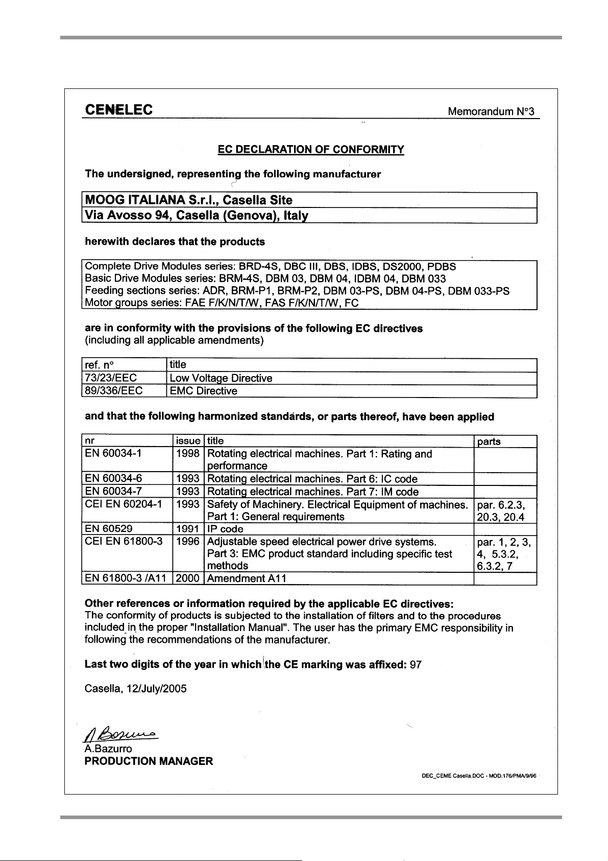
I.4 EC DECLARATION OF CONFORMITY
I.7
DS2000 USER’S MANUAL (rev.C)
Page 10

I.8
INDEX
I.5 EC REQUIREMENTS
Cautionary Marking. See previous page.
Protection against electric shock. Electronic Equipment intended for installation in
closed electrical operating areas kept locked. Where Electronic Equipment requires
manual intervention, 412.2.1 of HD 384.4.41 S2 shall be consulted.
Fixed connection for protection. The equipment may have a continuous leakage
current of more than A.C. 3.5 mA or D.C. 10 mA in normal use and a fixed ground
connection is required for protection.
RCD. When the protection in installations with regard to indirect contact is achieved by
means of an RCD, their appropriate function/combination shall be verified. In any case
only a residual-current-operated protective device (RCD) of Type B is allowed. In fact a
D.C component can occur in the fault current in the event of a fault connection to earth.
Climatic Conditions. Equipment intended to operate within its performance specification
over the range of Class 3K3, as defined in table 1 of EN 60721-3-1, EN 60721-3-2, EN
60721-3-3, EN 60721-3-4, partly modified.
Pollution Degree 2 Installation. The equipment shall be placed in a pollution degree 2
environment, where normally only non-conductive pollution occurs. Occasionally,
however, a temporary conductivity caused by condensation is to be expected, when the
electronic equipment is out of operation.
EMC Requirements. The installer of the equipment is responsible for ensuring
compliance with the EMC standards that apply where the equipment is to be used.
Product conformity is subjected to filters installation and to recommended procedures, as
from section 3 of this manual.
Second Environment (EMC). Equipment intended to be connected to an industrial low-
voltage power supply network, or public network that does not supply buildings used for
domestic purposes (second environment, according to EMC Standards). It is not intended
to be used on a low-voltage public network that supplies domestic premises (first
environment). Radio frequency interference is expected if used on such a network.
Recovery Resistor Cable. Shielding of the recovery resistor cable, provided in kit for test
purposes, is recommended for ensuring compliance with the EMC standards.
Large-Scale Stationary Industrial Tools (WEEE, RoHS). Equipment intended for
installation as part of large-scale stationary industrial tools, covered by the exception of
Annex IA, No.6, of the European Directives 2002/96/EC (WEEE) and 2002/95/EC
(RoHS).
DS2000 USER’S MANUAL (rev.C)
Page 11
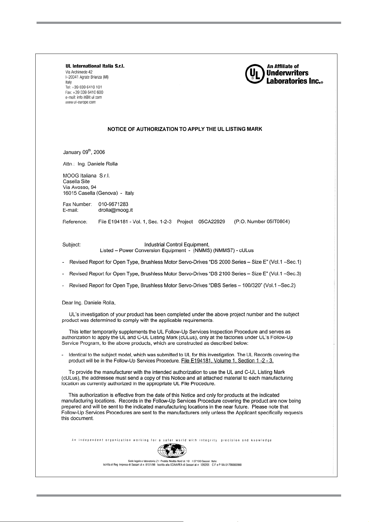
I.6 UL AUTHORIZATION (page 1)
INDEX
I.9
DS2000 USER’S MANUAL (rev.C)
Page 12
I.10
UL AUTHORIZATION (page 2)
INDEX
DS2000 USER’S MANUAL (rev.C)
Page 13

INDEX
I.11
I.7 UL REQUIREMENTS
• These Brushless Servo-Drives shall be assembled with the guidelines specified in this
Manual. Only the configurations with the components tested and described in the UL
Report, file E194181, Vol.1, Sec.1, Issue date 01-21-00 and following Revisions can bear
the Listing Mark.
• These drives shall be used within their ratings, as specified in the marking of the
equipment.
• Cautionary Marking. See Accident Protection page.
• Surrounding Air Temperature. "Maximum Surrounding Air Temperature 40°C". In the
final installation considerations shall be given for the need of repeating Temperature test if
the unit is mounted with a different Surrounding Air conditions.
• Pollution degree 2 Installation. The drive must be placed in a pollution degree 2
Environment.
• Environmental designation. “Open Type Equipment”.
• Short Circuit Ratings.
DS2000 3/9, 4/12, 6/15, 8/22, 14/42, 20/45, 25/70, 35/90, 50/140: “Equipment suitable
for use on a circuit capable of delivering not more than 5000 rms Symmetrical
Amperes, 460 Vac +10% maximum”
DS2000 60/180, 100/300: “Equipment suitable for use on a circuit capable of delivering
not more than 10000 rms Symmetrical Amperes, 460 Vac +10% maximum”
• Branch Circuit Protection. The Branch Circuit Protection for Short Circuit shall be
provided in the end-use applications by external R/C Fuses (JFHR2), manufactured by
Busman Div Cooper (UK) LTD, Semiconductor fuse type, rated 660 Vac, 200 kA A.I.C.,
Mod. No. as follows:
DS2000 3/9, 4/12, 6/15, 8/22, 14/42: Mod. No. 50 FE, rated 50 Amps
DS2000 20/45, 25/70, 35/90: Mod. No. 100 FE, rated 100 Amps
DS2000 50/140, 60/180: Mod. No. 160 FEE, rated 160 Amps
DS2000 100/300: Mod. No, 315-FM, rated 315 Amps
• Overspeed Protection. The Power Conversion Equipment is incorporating an Overspeed
Protection. See MV command in section 6.
• Overvoltage Control. In the equipment the Overvoltage is controlled by a Transient
Suppressive device, with 1500 V Clamping Voltage and min 120 J (10x1000 us or 2 ms)
Energy Handling Capability. See also “Bus not normal” protection in section 6.
• Overload Protection. The equipment does not incorporate internal overload protection
for the motor load. The drive is intended to be used with motors that must have integral
thermal protection through a PTC or NTC. The overtemperature fault of the drive will trip
when the PTC reaches 2 kW or 6.5kW for the NTC. See J4 connector in section 2 of this
manual for wiring.
DS2000 USER’S MANUAL (rev.C)
Page 14

I.12
INDEX
• Over-Current Protection. The drive is provided with a current limiting circuitry. See
ANALOG ILIMIT and I2T commands in section 6.
• Wiring. Wiring shall be made by stranded and/or solid, copper (Cu), 60/75°C (140/167°F)
conductor only, and, for terminal blocks, the tightening torque values specified in section 2
of this manual shall be applied. These requirements do not pertain to control circuit
terminals.
• Wiring of Recovery Resistor. The Dynamic Brake Unit Recovery Resistor, when
external, shall have the connection wiring made with R/C (AVLV2) or insulated with R/C
(YDPU2) or R/C (UZCW2) in the end-use installation.
• Transient Suppression Devices. Input power wiring, only for size A and B, shall be
protected by external Transient Suppression Devices, such as varistors or transient
voltage surge protections, evaluated to the component requirements in UL1449. the
following devices are recommended:
Rating
Drive
A and B
size
Ref.
Code
AS5046
Manufacturer
Littelfuse Inc
Epcos Ohg
S A BC
Components NV
TVSS
Mod. No.
V-575-LA-40-
A
S14-K-550
S20-K-550
2322 595.551
Operating
Voltage
(V
)
ac
575 V
rms
max
550 V
rms
max
550 V
rms
max
550 V
rms
max
Clamping
Voltage
(Vac)
1500
1500
1500
1500
Maximum
Energy (J)
120
(10x1000µs)
120
(2ms)
210
(2ms)
160
(10x1000µs)
Max
Op.
Temp
85°C
85°C
85°C
85°C
Qty
3
DS2000 USER’S MANUAL (rev.C)
Page 15
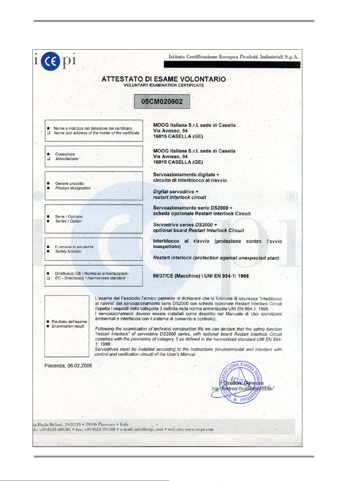
I.8 ICEPI CERTIFICATE
INDEX
I.13
DS2000 USER’S MANUAL (rev.C)
Page 16

I.14
INDEX
I.9 SAFETY REQUIREMENTS (RESTART INTERLOCK FUNCTION)
• Complete Standstill. The Restart Interlock safety function prevents motor unexpectedly
starting from standstill. This circuit can be used in the “Safe Standstill” machine function.
When the motor is rotating, the switching-on of the Restart Interlock provides an
uncontrolled stop (category 0 according to EN 60204-1:1997). When a controlled stop of
category 1, according to EN 60204-1:1997, is requested, the condition of stopped motor
must be assured. The final machine must be able to stop the motor.
WARNING: The designer must evaluate the machine stopping time during the risk
assessment even in case of failure. The machine can present a dangerous overrun
in case of failure of the drive. Other protective measure are needed to achieve a
safe condition.
• Environmental Conditions. Equipment intended to operate within the following
environmental conditions:
◊ Ambient temperature: 0 to +40°C
◊ EMC immunity: according to EN 61800-3/A11:2000 (Adjustable speed electrical power
drive systems. Part 3: EMC product standard including specific test methods). Second
environment (industrial)
◊ Vibration immunity: 2 to 12Hz, 1.5 mm amplitude (peak); 12 to 200Hz, 1 g acceleration
◊ Shock immunity: 10 g, half sine, 11 ms, according to EN 60721-3-3:1995, Class 3M4
• Enlosure. Electronic Equipment intended for installation in an enclosure providing at least
IP54 protection.
• Pollution Degree 2. The equipment shall be installed in a pollution degree 2 environment,
where normally only non-conductive pollution occurs. Occasionally, however, a temporary
conductivity caused by condensation is to be expected, when the electronic equipment is
out of operation.
WARNING: When the Restart Interlock Circuit is activated, the motor can no longer
generate a torque. Motors which are not automatically clamped when powered
down (e.g. vertical/inclined axes), must be clamped using a mechanical brake
DS2000 USER’S MANUAL (rev.C)
Page 17

INDEX
I.15
I.10 LEGAL ASPECTS
This manual can be used only by final Customers/Users of the Moog product it describes and
only for proper installation purposes.
This manual cannot be reproduced in whole or in part without the prior written consent of
Moog.
No transmission or diffusion of this manual, under electronic, mechanical, or printed form, is
allowed.
Moog issued this manual attempting to ensure a complete information; anyway, Moog shall
not be liable for errors or omissions contained herein and for incidental or consequential
damages due to the above mentioned errors and omissions.
Moog reserves the right to change and update this manual without notice.
This manual has a merely information purpose. There is no obligation for Moog as regard the
correspondence of the product features described in the manual with the features of the real
product purchased by the final Customer/User.
No statement or sentence contained in this manual implies further legal obligations different
from the ones contained in each single sale or supply contract concerning Moog products.
DS2000 USER’S MANUAL (rev.C)
Page 18

I.16
INDEX
THIS PAGE INTENTIONALLY BLANK
DS2000 USER’S MANUAL (rev.C)
Page 19

SECTION ONE – DESCRIPTION
1.1
1. DESCRIPTION
1.1 INTRODUCTION
This section describes the DS2000 drive series, providing information about the coding
system. Such data allow understanding the DS2000 characteristics and makes clear the
necessary concepts to access the following sections.
DS2000 USER’S MANUAL (rev.C)
Page 20

1.2
SECTION ONE – DESCRIPTION
1.2 PRODUCT RANGE
DS2000 is a full digital drive series for permanent magnet synchronous servomotors
(hereinafter: brushless) and for vector control asynchronous servomotors (hereinafter:
asynchronous).
The range is made up of 11 models, corresponding to 3, 4, 6, 8, 14, 20, 25, 30, 50, 60 and
100 A
nominal currents.
rms
The standard transducers provided with the motor are the incremental encoder or the
resolver (with its simulated encoder).
The recovery resistors are placed outside the drive; only the 3, 4, and 6 A models can be
equipped with built-in recovery resistor (optional).
DS2000 drive is provided together with this manual and the Application Notes in the
Appendix of DS2000 user’s manual, for a deep understanding and the best use of the
product.
1.3 GENERAL FEATURES
The DS2000 features provide the automation industry with the best response to the hardest
requirements related to motion control:
FULL DIGITAL:
• Speed and current control loops and many other functions, as the DC BUS status
monitoring, the soft-start and recovery circuit management, and the protections
thresholds detection are carried out through numeric algorithms.
• The digital mode allows a maximum stability related to the aging, the temperature and
the various application cases.
• Settings are carried out through numbers calculated by means of analytic models and
do not depend upon analog calibrations.
FLEXIBLE:
• Any brushless motor can be very well driven by entering a maximum of 8 parameters
which adjust the current loop and identify the motor electromechanical characteristics
(peak current, electromotive force, inductance, resistor, poles number, voltage rating,
speed).
• Any asynchronous motor can be very well driven by vector control, working as a
brushless servomotor; by entering the magnetization current (ID) and the slip gain
(frequency) additional parameters it is possible to use any kind of asynchronous
motor. The other parameters, the ones in connection with the hardware features in
common with brushless motors, remain active.
• The motor transducer can be both a resolver (2 to 24 poles) and an incremental
encoder (1024 to 8192 pulses).
• It is possible to program the device in 2 different languages: Italian and English. The
required language should be specified in the purchase order.
• The power supply voltage range can be from Three-phase 65 Vac to 510 Vac with no
previous setup.
• With power supply voltages lower than 120 Vac Three-phase, it is necessary to supply
a 24 Vdc auxiliary voltage.
DS2000 USER’S MANUAL (rev.C)
Page 21

SECTION ONE – DESCRIPTION
ADVANCED PERFORMANCE:
• The current loop, based on a traditional PI structure, is provided with automatic
compensation algorithms of the EMF and of the KP/KI ratio, as a function of the motor
characteristics.
• Hardware calibrations are not necessary for the current loop, but they are necessary
for parameters setting.
• Current loops are closed at 10kHz.
• The speed loop is closed at 5kHz.
• Additional phase advance is provided.
1.4 TECHNICAL DATA
1.4.1 ELECTRICAL AND MECHANICAL SPECIFICATIONS
Three-phase input voltage rating: 230V
Min/max Three-phase input voltage
- With 24 V
- Without 24 V
auxiliary input voltage: 65 / 510 Vac (DC-BUS: 80 / 720 Vdc)
dc
auxiliary input voltage: 120 / 510 Vac (DC-BUS: 150 / 720 Vdc)
dc
Auxiliary voltage: 24 V
Configurable analog references: 3.2 to 10 V
Max dynamic with encoder: 200 Hz
Switching frequency: 10 kHz
Speed adjustment: 0 to 9999 rpm
Anti-resonance low-pass filter: 20 to 800 Hz
Filter on reference: 1 to 800 Hz
Notch filter (programmable): 50 to 1500 Hz
Output current
Model
Nominal
(A
)
rms
3/9 3 6.4 9 4.5 A
4/12 4 8.5 12 4.5 A
6/15 6 10.6 15 4.5 A
8/22 8 15.6 22 4.5 A
14/42 14 29.7 42 6 B
20/45 20 31.8 45 10 C
25/70 25 49.5 70 10 C
30/90 30 63.6 90 10 C
50/140 50 99.0 140 23 D
60/180 60 127.3 180 23 D
100/300 100 212.7 300 40 E
Tab. 1.0 – Mechanical and electrical characteristics
to 460Vac ±10%, 50/60 Hz
ac
±10% , 1.5A
dc
dc
Max
(A
rms
)
Peak
(A)
Mass
(kg)
Size
1.3
DS2000 USER’S MANUAL (rev.C)
Page 22

1.4
SECTION ONE – DESCRIPTION
1.4.2 CLIMATIC CONDITIONS
1.4.2.1 AMBIENT TEMPERATURE
0°C to +40°C (exceeding EN 60204-1:1997, par.4.4.3).
1.4.2.2 AMBIENT HUMIDITY
5% to 85% with no condensation and no formation of ice (according to EN 50178:1997,
weather protected site).
1.4.2.3 ALTITUDE
The electrical equipment is able to operating correctly at altitudes up to 1000m above sea
level (according to EN 60204-1:1997, par.4.4.5)
1.4.2.4 TRANSPORTATION AND STORAGE
The electrical equipment withstands the effects of transportation and storage
temperatures within a range of –25°C to +55°C and for short periods not exceeding 24 h
at up to +70°C (according to EN 60204-1:1997, par.4.5).
1.4.2.5 POLLUTION
The equipment has been designed according to pollution degree 2, where normally only
non-conductive pollution occurs. Occasionally, however, a temporary conductivity caused
by condensation is to be expected, when the electronic equipment is out of operation.
1.4.3 OTHER MECHANICAL SPECIFICATIONS
1.4.3.1 IMMUNITY TO MECHANICAL VIBRATION
0.075mm amplitude from 10 Hz to 57 Hz, 1g acceleration from 57 Hz to 150 Hz
(according to EN 50178:1997 and to IEC 68-2-6:1995, Fc test).
DS2000 USER’S MANUAL (rev.C)
Page 23

SECTION ONE – DESCRIPTION
1.4.4 INTERFACES
• Analog
Speed (or current) reference differential input: 0 +/- 10V (adjustable scale)
Auxiliary input voltage: 24Vdc ±10%
Output Voltage: 15Vdc
Analog output (configurable)
Tachometric signal (adjustable scale)
Peak current limit (trough adjustable analog signal)
Motor temperature (trough PTC or NTC)
Resolver interface
Sine Encoder Interface (optional)
• Digital
RS485 full-duplex serial link
Encoder input (incremental)
Encoder output (incremental)
Reset
Drive OK output
Drive enable input (torque)
Reference enable input (speed)
CAN BUS (optional)
1.4.5 PROTECTIONS
• Motor over temperature
• Drive over temperature
• Input voltage out of tolerance
• Encoder or resolver signal missed
• Encoder or resolver faulty connections
• Axis short circuit (motor and recovery resistor output)
• Recovery resistor missed (overvoltage)
• Recovery resistor overload (software selectable)
• Over speed in torque mode control (if speed is 12% above max set value).
• IGBT over temperature (software selectable)
• Anti-free-wheeling (software selectable)
• Safety – Restart interlock function (optional).
1.5
DS2000 USER’S MANUAL (rev.C)
Page 24

1.6
SECTION ONE – DESCRIPTION
1.5 STANDARD VERSIONS CODES
DS2000 drives are marked by a code identifying both the current supplied by the Model and
the eventual internal recovery resistor.
Codes correspond to:
• Standard Italian software drives
• 6 poles resolver (transformation ratio:0. 29), ¼ marker configured, 1024 simulated
encoder pulses
• External recovery resistor, provided with the drive together with mating connectors.
The following table summarizes the drive codes:
Model
Code Type
CZ1000C0A 3/9 A
CZ1001C0A 4/12 A
CZ1002C0A 6/15 A
CZ1003C0A 8/22 A
CZ1008C0A 14/42 B
CZ1005C0A 20/45 C
CZ1006C0A 25/70 C
CZ1007C0A 30/90 C
CZ1009C0A 50/140 D
CZ1010C0A 60/180 D
CZ1011C0A 100/300 E
Size
Tab. 1.1 – Standard versions codes
Besides the coding in Tab. 1.1, a new coding formed by a descriptive code has been
introduced, which univocally and directly identifies a drive and its configuration.
Fig. 1.1 shows the new codifications .
DS2000 USER’S MANUAL (rev.C)
Page 25

SECTION ONE – DESCRIPTION
1.7
1.6 SPECIAL VERSIONS CODES
For a limited braking power dissipation application, special versions of 3/9, 4/12, and 6/15
Size drives have been realized with built-in recovery resistor. Their codes are different, but all
the other features and the operation remain the same.
Codes correspond to:
• Standard Italian software drives
• 6 poles resolver (transformation ratio:0. 29), ¼ marker configured, 1024 simulated
encoder pulses
• Mating connectors provided with the drive
The following table summarizes the drive codes:
Model
Code Type
CZ1100C0A 3/9 A
CZ1101C0A 4/12 A
CZ1102C0A 6/15 A
Size
Tab. 1.2 – Special versions codes
Additional informations can be found in Section 2 and Section 5.
DS2000 USER’S MANUAL (rev.C)
Page 26
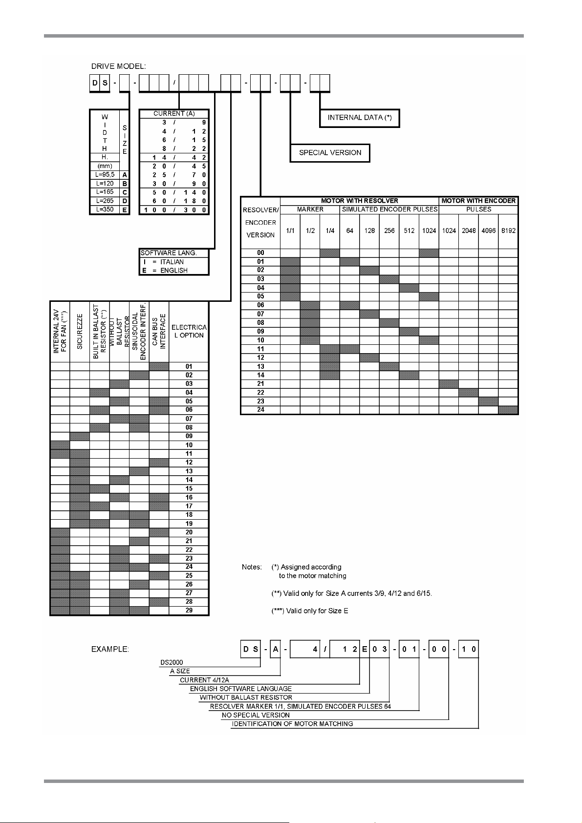
1.8
SECTION ONE – DESCRIPTION
Fig. 1.1 – Table of DS2000 codification
DS2000 USER’S MANUAL (rev.C)
Page 27
SECTION ONE – DESCRIPTION
1.9
1.7 OPTIONS
Optional devices can be built-in or separately supplied.
Built-in drive devices are:
• CAN BUS interface on speed reference (SW Release 4.X00)
• Safety – Restart interlock function
• 24V fans internal power supply (only size E)
Separately supplied devices are:
• RS232/422/485 Converter (Moog code CZ5200)
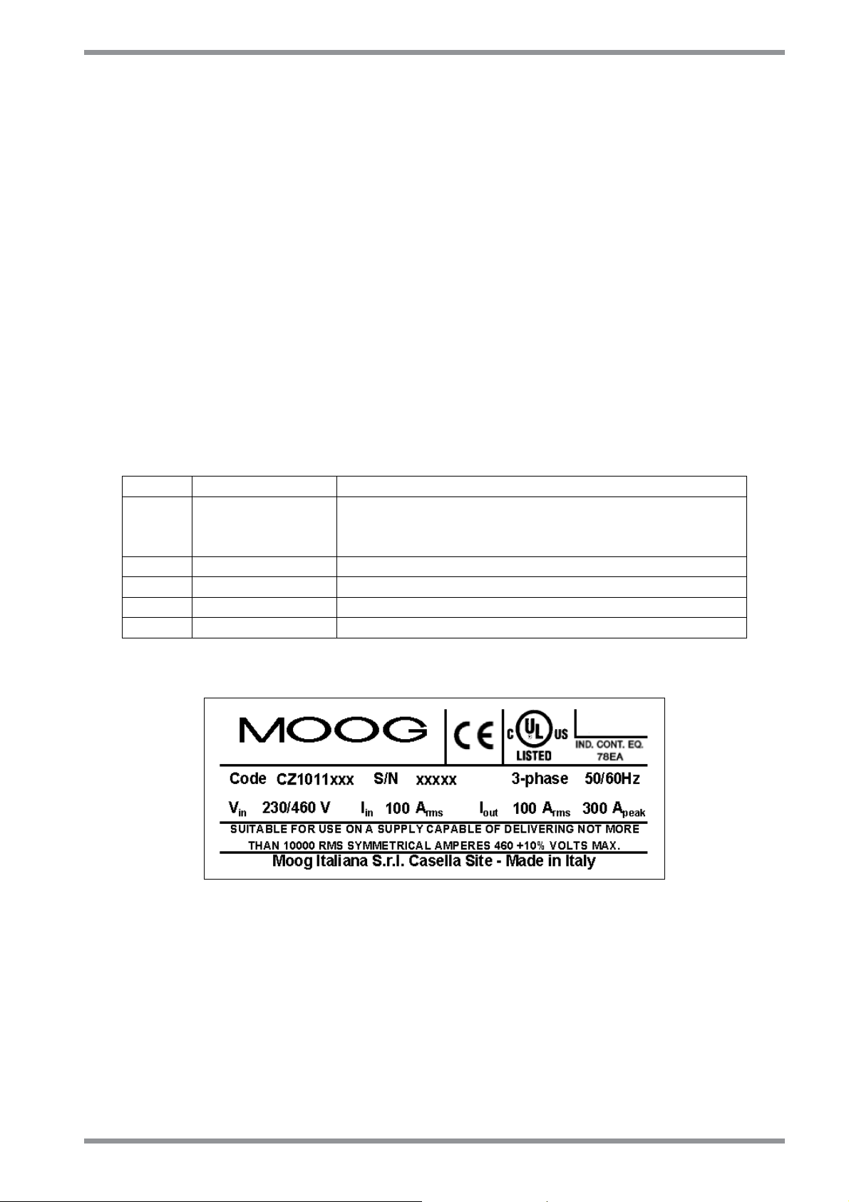
1.8 SERIAL NUMBER – NAMEPLATE
Each drive is provided with a serial number identifying the Model, any eventual option and
the manufacturing date. This number is a useful tool to verify, through the Moog Database,
the original software and firmware revision.
Using these data it is possible to carefully support the final Customers. It is recommended to
take note of the serial number, which is present on each drive, before shipment.
CODE: CZxxxxYYz Product code
S/N: AASSNNNNYYA Serial number, where
AA= year, SS= week, NNNN= progressive number,
YYA= option (C0A= standard version)
Vin: xxx V Input voltage rating
Iin: xxx Arms Nominal effective input current
Iout: xxx Arms Nominal effective output current
Iout: xxx Apeak Output peak max current
Fig. 1.2 – Nameplate
DS2000 USER’S MANUAL (rev.C)
Page 28

1.10
SECTION ONE – DESCRIPTION
THIS PAGE INTENTIONALLY BLANK
DS2000 USER’S MANUAL (rev.C)
Page 29

SECTION TWO – WIRING AND INSTALLATION
2.1
2. GENERAL INFORMATION
2.1 INTRODUCTION
This section describes the installation, wiring and cabling of the Moog DS2000 servo drive
series. Such information allows the understanding of DS2000 functionality and makes clear
the necessary concepts to access the following sections.
DS2000 USER’S MANUAL (rev.C)
Page 30
2.2
SECTION TWO – WIRING AND INSTALLATION
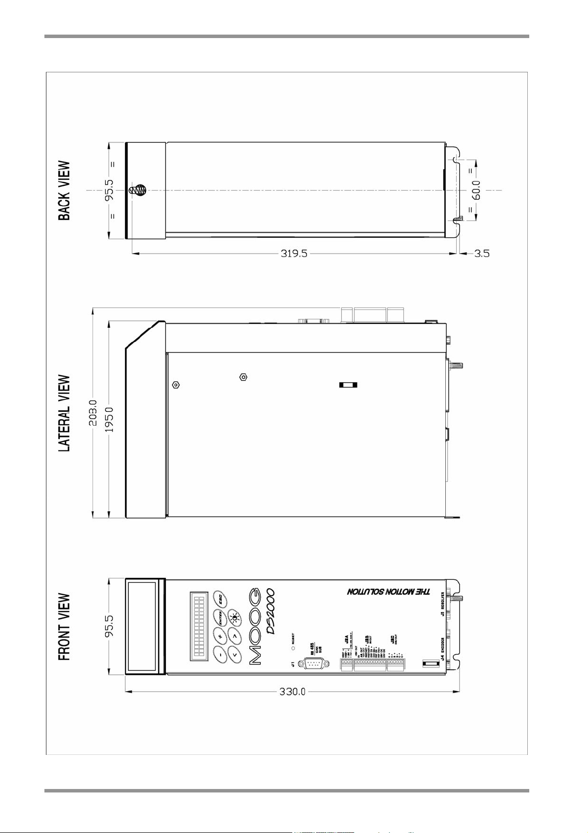
2.2 DIMENSIONS AND DRILLING JIG
Fig. 2.1 – Size A dimensions and drilling jig (mm)
DS2000 USER’S MANUAL (rev.C)
Page 31

SECTION TWO – WIRING AND INSTALLATION
2.3
Fig. 2.2 – Size B dimensions and drilling jig (mm)
DS2000 USER’S MANUAL (rev.C)
Page 32

2.4
SECTION TWO – WIRING AND INSTALLATION
Fig. 2.3 – Size C dimensions and drilling jig (mm)
DS2000 USER’S MANUAL (rev.C)
Page 33

SECTION TWO – WIRING AND INSTALLATION
2.5
Fig. 2.4 – Size D dimensions and drilling jig (mm)
DS2000 USER’S MANUAL (rev.C)
Page 34

2.6
SECTION TWO – WIRING AND INSTALLATION
Fig. 2.4.1 – Size E dimensions and drilling jig (mm)
DS2000 USER’S MANUAL (rev.C)
Page 35
SECTION TWO – WIRING AND INSTALLATION
2.7
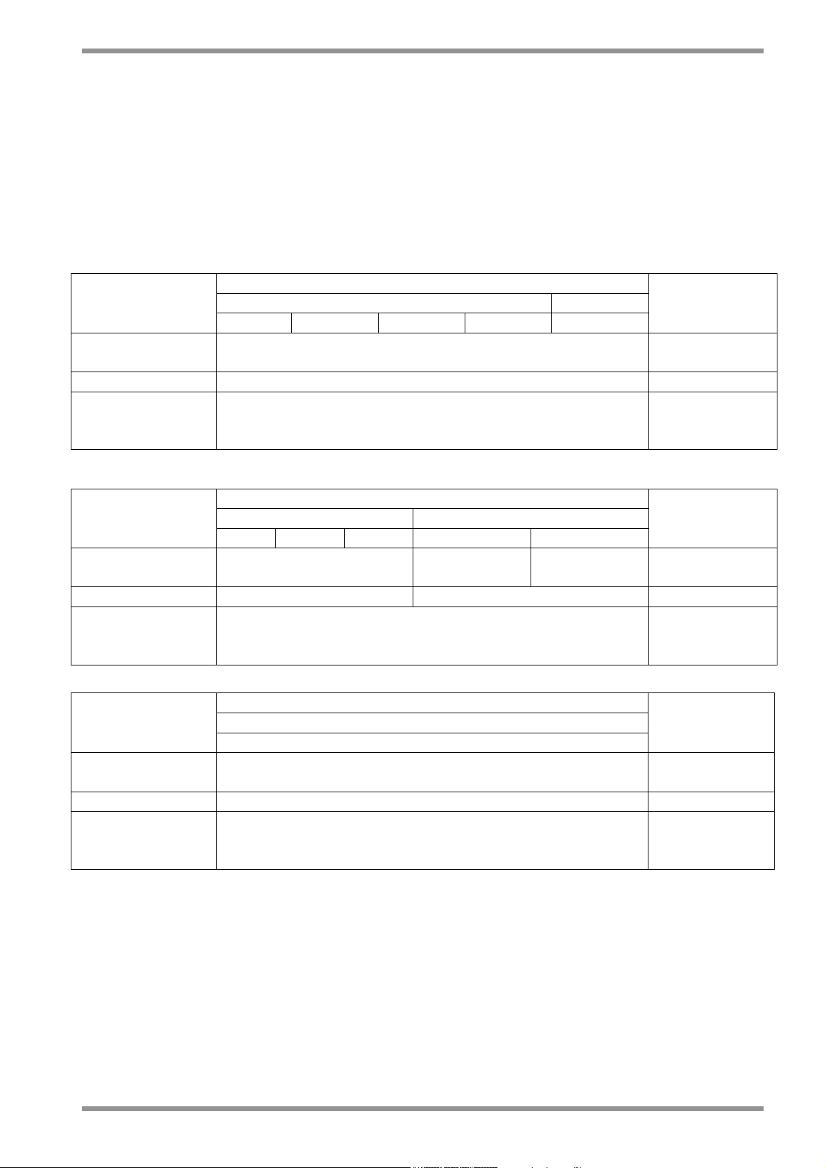
2.3 EXTERNAL FUSES
It is recommended to use the Short Circuit protection in the final application with UL certified
external fuses (cat. JFHR2), manufactured by Bussmann Div. Cooper (UK) Ltd,
semiconductor type, 660 V
As alternate fuses by different manufacturers can be used but UL approved (cat. JFHR2) with
the same data of the fuses shown in table taking care that the Peack-let-trough-current
(A.I.C) and clearing I2T are equal or lower.
3/9 4/12 6/15 8/22 14/42
Short Circuit
Rating
Power line fuse 50 – FE Semiconductor
24 Vdc auxiliary
power supply
fuse
20/45 25/70 30/90 50/140 60/180
Short Circuit
Rating
Power line fuse 100 – FE 160 – FEE Semiconductor
24 Vdc auxiliary
power supply
fuse
, 200 kA symmetrical A.I.C..
ac
DS2000 MODEL
A size B size
5000 rms Amps symmetrical
3A / 250V Delayed
DS2000 MODEL
C size D size
5000 rms Amps
symmetrical
5000 rms
Amps symm.
3A / 250V Delayed
10000 rms
Amps symm.
Notes
Notes
DS2000 MODEL
E size
Notes
100/300
Short Circuit
Rating
10000 rms Amps symmetrical
Power line fuse 315-FM Semiconductor
24 Vdc auxiliary
power supply
3A / 250V Delayed
fuse
Tab. 2.1 – Recommended fuses
DS2000 USER’S MANUAL (rev.C)
Page 36

2.8
SECTION TWO – WIRING AND INSTALLATION
2.4 POWER DISSIPATION
For the thermal sizing of the cabinet in which the drive is installed, it is necessary to refer to
the table. If the application implies continuous braking, it is necessary to add the recovery
resistor power dissipation (use the nominal power if the one required by the application is
unknown).
DS2000 Model Power
3/9 60W
4/12 75W
6/15 90W
8/22 110W
14/42 180W
20/45 250W
25/70 300W
30/90 400W
50/140 650W
60/180 800W
100/300 1200W
Tab. 2.2 – Power dissipation at nominal current
2.5 SOFT-START
The soft-start circuit (current limit at start-up) is included in the drive input stage. Additional
data about the soft-start circuit can be found in the Section 5.
DS2000 USER’S MANUAL (rev.C)
Page 37
SECTION TWO – WIRING AND INSTALLATION
2.9
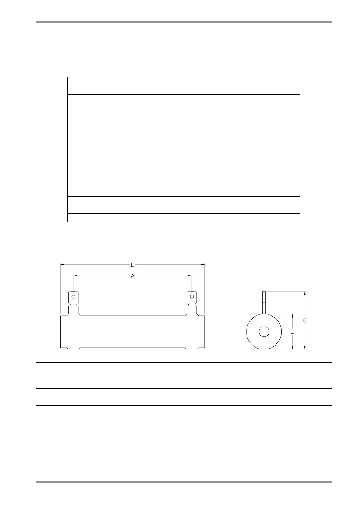
2.6 RECOVERY CIRCUIT
Standard recovery resistors are in the following table (see Section 5 for additional
informations) :
Dynamic braking unit
DS2000 Standard recovery resistor for 400/460 Vac mains voltage
Model Resistor and power Max Current Max Duty Cycle
3/9
4/12
6/15
8/22
14/42 33Ω/250W (ext.) 22.7A 1.5%
20/45
25/70
30/90
50/140
60/180
100/300 3.9Ω/1000W (ext.) 192.3A 0.7%
3/9
4/12
6/15 56Ω/150W (int.) 13.4A 0.7%
75Ω/100W (ext.) 10A 1.3%
51Ω/200W (ext.) 14.7A 1.8%
12Ω/370W (ext.) 62.5A 0.8%
10Ω/750W (ext.) 75.0A 1.3%
82Ω/150W (int.) 9.1A 1.0%
Tab. 2.3 – Recovery resistor data
Dimensions declared by the supplier are in the following table:
Model 75Ω/100W 51Ω/200W 33Ω/250W 12Ω/370W 10Ω/750W 3.9Ω/1000W
L [mm] 165 ± 2 215 ± 2.5 265 ± 3 265 ± 3 300 ± 5 400 ± 5
A [mm] 150 ± 2 200 ± 2.5 250 ± 3 241 ± 3 270 ± 5 370 ± 5
G [mm] 36 ± 2 46 ± 2 46 ± 2 53 ± 2 88 ± 2 88 ± 2
D [mm] 20.5 ± 1 30.5 ± 1 30.5 ± 1 39 ± 2 76 ± 2 76 ± 2
Tab. 2.4 – Mechanical data of recovery resistor
DS2000 USER’S MANUAL (rev.C)
Page 38

2.10
SECTION TWO – WIRING AND INSTALLATION
2.7 FANS
DS2000 ventilation is provided by one or more fans mounted over the drive and under only
for size E. The fans input power is internally supplied except for size E (option “internal 24V”)
CAUTION: A free air circulation must be ensured for a proper operation as per the following
table..
DS2000
Size
Minimum Clearence Top
(mm)
Minimum Clearence Bottom
(mm)
A 60 100
B 60 100
C 80 160
D 100 200
E 200 300
Tab. 2.5A – Minimum Clearence around DS2000 Drives
2.8 RESET OR RESTART BUTTON
The reset (restart) button is on the drive front panel. It allows the digital control card reinitialization as well as the protections reset.
DS2000 USER’S MANUAL (rev.C)
Page 39
SECTION TWO – WIRING AND INSTALLATION
2.11
2.9 CONNECTION CABLES
Connection cables must have precise electric characteristics in order to ensure a proper
operation of the servosystem. It is recommended to use copper (Cu) cables, 75°C, UL
certified, according to the cross sections indicated in the table 2.5. The following table shows
the cables specification for each single function.
DS2000 MODEL
Cable
A
Size
B
Size
C
Size
D Size
50/140 60/180
E
Size
Line power 14 AWG 12 AWG 8 AWG 6 AWG 4 AWG 1 AWG
Protective bonding 6 AWG 6 AWG 6 AWG 6 AWG 4 AWG 1 AWG
Motor power cable 14 AWG 12 AWG 8 AWG 6 AWG 4 AWG 1 AWG Shielded
DC BUS (+/-AT) 14 AWG 12 AWG 8 AWG 6 AWG 4 AWG 1 AWG Shielded
Recovery resistor 14 AWG 12 AWG 8 AWG 6 AWG 4 AWG 2 AWG Shielded
24V fans cable 14 AWG Shielded
Restart Interlock 22 AWG Shielded
24V power supply 14 AWG Shielded
Motor encoder 22/20 AWG Shielded
Motor resolver 22/20 AWG Shielded
Notes
Tab. 2.6 – Wiring size
CAUTION: To connect more than one drive through the DC BUS (+/-HV), please ask the
Service Center.
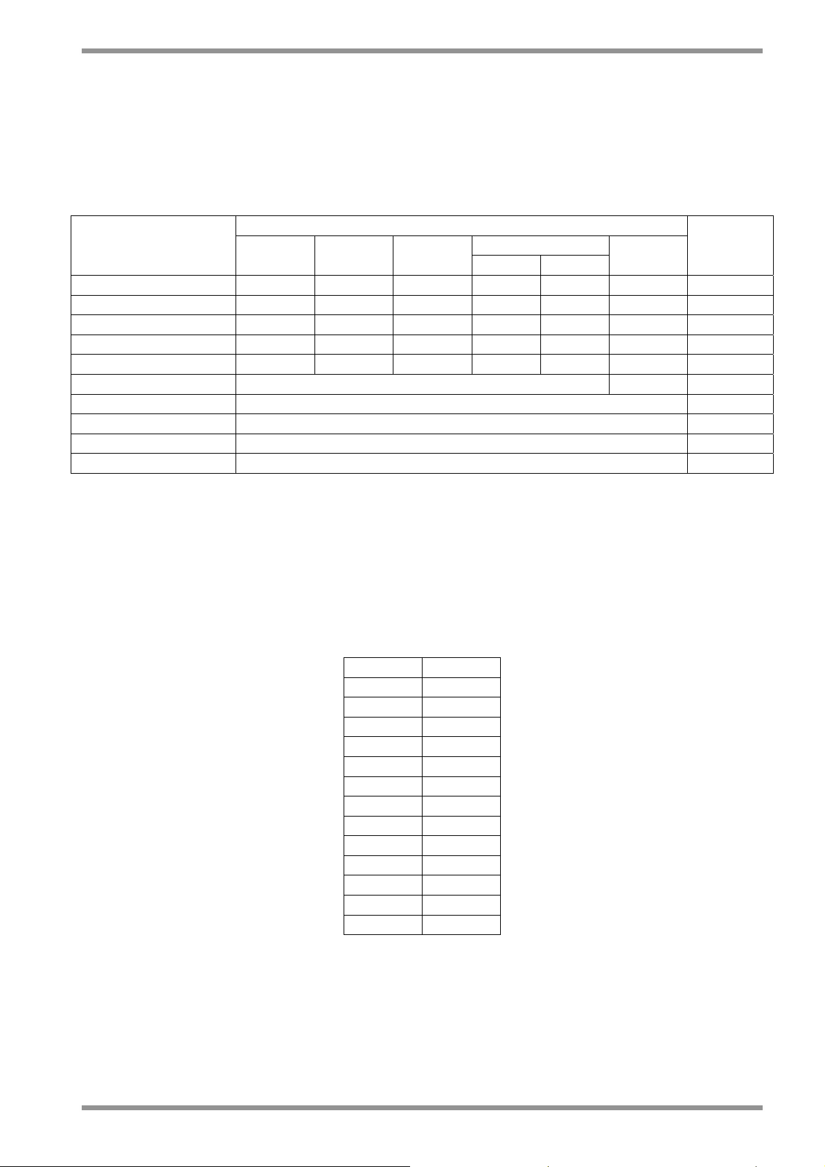
2.10 AWG/mm2 CONVERSION
AWG mm
22 0.3
20 0.5
18 0.8
16 1.3
14 2.1
12 3.3
10 5.3
8 8.4
6 13
4 21
3 27
2 34
1 42
2
Tab. 2.7 – AWG/mm2 conversion
DS2000 USER’S MANUAL (rev.C)
Page 40

2.12
SECTION TWO – WIRING AND INSTALLATION
2.11 WIRING AND CONNECTORS
NOTE: Moog DS2000 drives are equipped with all the necessary connectors for a proper
operation. It is not necessary to indicate the connectors, or the recovery resistor in the
purchase order. All of them are included in the drive code.
All the drives (except D size and E size) are equipped with plug-in connectors to ensure a
quick connection of the drive to the switchboard and for Service activities (if applicable).
2.11.1 POWER CONNECTORS
Connectors differ according to the different drive sizes: please, refer to the following
descriptions and tables to detect the corresponding pin configuration; power connectors
bear a pinout label which makes pin detection easier.
2.11.1.1 SIZE A and B POWER CONNECTOR
Note: Pin 1 is marked with the symbol “■”
Fig. 2.5 – Size A and B power connector
• J6 connector
- Mating connector: female. 12 pins, supplied with the drive, model Tyco 1-282960-2 or
1-796981-2 (Moog code AK4987).
Wire stripping: 7 mm. Tightening torque: 0.5Nm.
Pos. Name Function
1 ■ -AT - DC BUS AT
2 RR (+AT) External recovery resistor and +AT of DC BUS
3 RR External recovery resistor
4 U1 Phase "L1", three-phase voltage input 230/460Vac ±10%
5 V1 Phase "L2", three-phase voltage input 230/460Vac ±10%
6 W1 Phase "L3", three-phase voltage input 230/460Vac ±10%
7 GND Motor ground (see also Ground screw)
8 W2 Phase "W2", motor three-phase output
9 V2 Phase "V2", motor three-phase output
10 U2 Phase "U2", motor three-phase output
11 +24V
12 0V (24)
Auxiliary voltage inputs 24 Vdc ±10%, 2A
(pin 12 is connected to drive logic 0)
Tab. 2.8 – J6 connector, size A and B
DS2000 USER’S MANUAL (rev.C)
Page 41

SECTION TWO – WIRING AND INSTALLATION
• Ground screw
Use a lug for M5 screw.
Pos. Name Function
Ground screw GND Equipotential protection circuit.
Tab. 2.9 – Ground screw, size A and B
NOTE: In an especially noisy environment (from an electromagnetic point of view) it can
be useful to connect the motor ground (pin 7 of J6 connector) to the ground screw.
2.13
DS2000 USER’S MANUAL (rev.C)
Page 42

2.14
SECTION TWO – WIRING AND INSTALLATION
2.11.1.2 SIZE C POWER CONNECTOR
Note: Pin 1 is marked with the symbol “■”
Fig. 2.6 – Size C power connector
• J6 connector
- Mating connector: female, 5 pins, crimp, supplied with the drive, model Molex 42816 0512 (Moog code AK4991).
Pos. Name Function
1 ■ W1 Phase "L3", three-phase voltage input 230/460Vac ±10%
2 V1 Phase "L2", three-phase voltage input 230/460Vac ±10%
3 U1 Phase "L1", three-phase voltage input 230/460Vac ±10%
4 RR (+ATP) External recovery resistor and +HV of DC BUS
5 RR External recovery resistor
Tab. 2.10 – J6 input power connector, size C
DS2000 USER’S MANUAL (rev.C)
Page 43

SECTION TWO – WIRING AND INSTALLATION
• J7 connector
- Mating connector: female, 4 pins, crimp, supplied with the drive, model Molex 42816 0412 (Moog code AK4990).
Pos. Name Function
1 ■ U2 Phase "U2", motor three-phase output
2 V2 Phase "V2", motor three-phase output
3 W2 Phase "W2", motor three-phase output
4 GND Motor ground (see also Ground screw)
Tab. 2.11 – J7 output motor power connector, size C
• J8 connector
- Mating connector: female, 2 pins, supplied with the drive, model Wago 231-102/026 000 (Moog code AK4967).
Pos. Name Function
1 ■ +24V
2 0V (24V)
Auxiliary voltage inputs 24 V
±10%, 2A
dc
(pin 2 is connected to drive logic 0)
2.15
Tab. 2.12 – J8 auxiliary input power supply connector, size C
• J9 connector
- Mating connector: female, 2 pins, crimp, supplied with the drive, model Molex 42816 0212 (Moog code AK4989).
Pos. Name Function
1 ■ -AT
2 +AT
DC BUS (see Application Engineer for details)
Tab. 2.13 – J9 DC BUS output connector, size C
• Ground screw
Use a lug for M5 screw.
Pos. Name Function
Ground screw GND Equipotential protection circuit.
Tab. 2.14 – Ground screw, size C
NOTE: In an especially noisy environment (from an electromagnetic point of view) it can
be useful to connect the motor ground (pin 4 of J7 connector) to the ground screw.
DS2000 USER’S MANUAL (rev.C)
Page 44

2.16
SECTION TWO – WIRING AND INSTALLATION
• WIRING NOTES FOR J6, J7, J9 CONNECTORS (SIZE C)
The relevant contacts (Molex type 42815-0031) are supplied together with J6, J7, and J9
mating connectors for C size DS2000 drives. These contacts are sized for an 8 AWG (8.4
mm2) cable with a 10 mm wire stripping. It is recommended the use of a Molex crimping
tool type 63814-0000, or Molex type 63811-1500, or equivalent. The crimping does not
affect the insulating plastic tubing. As an alternative it is possible to sold the contacts,
taking care of folding the contact wings.
After the crimping (or soldering), the contact must be inserted into the Mating connector
following the proper direction and must be kept in position by the TPA (Terminal Position
Assurance) jumper, according to Fig. 2.7.
Fig. 2.7 – Fixing Molex connectors
DS2000 USER’S MANUAL (rev.C)
Page 45
SECTION TWO – WIRING AND INSTALLATION
2.11.1.3 SIZE D POWER CONNECTOR
2.17
Note: Pin 1 is marked with the symbol “■”
Fig. 2.8 – Size D power connector
• J8 connector
- Mating connector: female, 2 pins, supplied with the drive, model Wago 231-102/026 000 (Moog code AK4967).
Pos. Name Function
1 ■ +24V
2 0V (24V)
Auxiliary voltage inputs 24 V
±10%, 2A
dc
(pin 2 is connected to drive logic 0)
Tab. 2.14D – J8 auxiliary input power supply connector, size D
DS2000 USER’S MANUAL (rev.C)
Page 46
2.18
SECTION TWO – WIRING AND INSTALLATION
• J9 Terminal block
- Pos.1 to 12 Phoenix - HDFK16: Wire stripping: 16 mm. Tightening torque: 2 Nm.
Pos. Name Function
1 ■ RR External recovery resistor
2 RR (+AT) External recovery resistor and +HV of DC BUS
3 GND Housing ground
4 U1 Phase "L1", three-phase voltage input 230/460Vac ±10%
5 V1 Phase "L2", three-phase voltage input 230/460Vac ±10%
6 W1 Phase "L3", three-phase voltage input 230/460Vac ±10%
7 U2 Phase "U2", motor three-phase output
8 V2 Phase "V2", motor three-phase output
9 W2 Phase "W2", motor three-phase output
10 GND Motor ground
11 +AT
12 -AT
DC BUS (see Application Engineer for details)
Tab. 2.15D – J9 power connector, size D
• Ground screw
Use a lug for M5 screw.
Pos. Name Function
Ground screw GND Equipotential protection circuit.
Tab. 2.16D – Ground screw, size D
NOTE: In an especially noisy environment (from an electromagnetic point of view) it can
be useful to connect the motor ground (terminal 10 of J9 connector) to the ground screw.
DS2000 USER’S MANUAL (rev.C)
Page 47
SECTION TWO – WIRING AND INSTALLATION
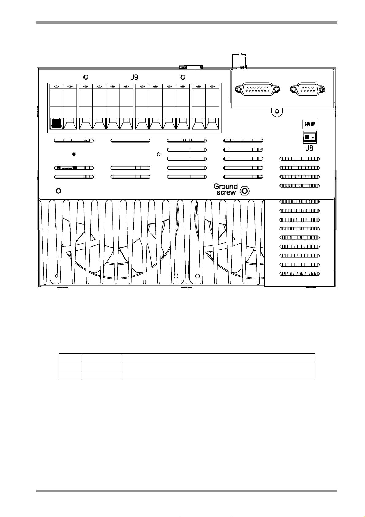
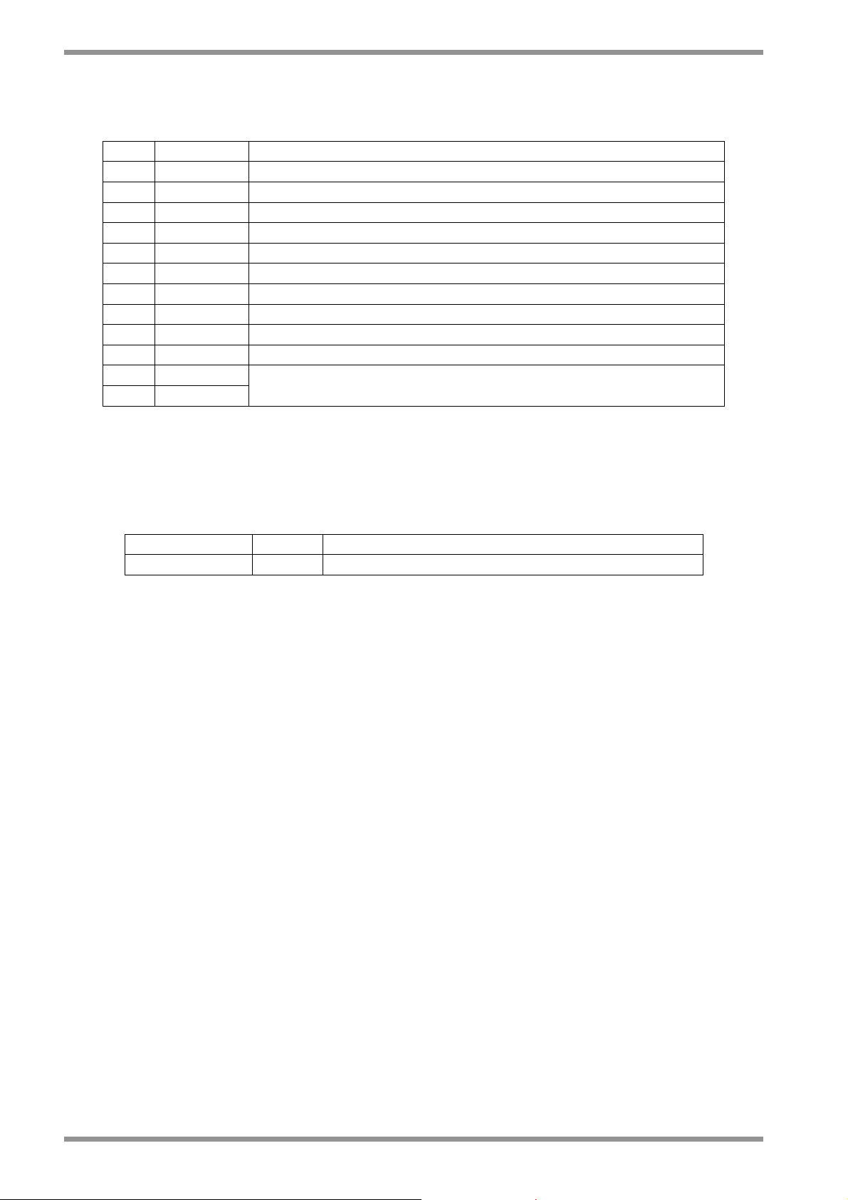
2.11.1.3.1 SIZE E POWER CONNECTOR
2.19
Note: Pin 1 is marked with the symbol “■”
Fig. 2.8.1 – Size E power connector
• J8 connector
- Mating connector: female, 2 pins, supplied with the drive, model Wago 231-102/026 000 (Moog code AK4967).
Pos. Name Function
1 ■ +24V
2 0V (24V)
Auxiliary voltage inputs 24 Vdc ±10%, 2A
(pin 2 is connected to drive logic 0)
Tab. 2.14E – J8 auxiliary input power supply connector, size E
DS2000 USER’S MANUAL (rev.C)
Page 48

2.20
SECTION TWO – WIRING AND INSTALLATION
• J9 Terminal block
- Pos. 1,2 Phoenix – HDFK4 : Wire stripping: 9 mm. Tightening torque: 0.7 Nm.
- Pos. 3,4 Phoenix – HDFK25 : Wire stripping: 19 mm. Tightening torque: 4 Nm.
- Pos. 5 to 14 Phoenix – HDFK50 : Wire stripping: 24 mm. Tightening torque: 8 Nm.
Pos. Name Function
1 ■ 24V fans
2 0V fans
Voltage inputs 24V
fans ±10%, 2A
dc
3 RR External recovery resistor
4 RR (+AT) External recovery resistor and +HV of DC BUS
5 GND Housing ground
6 U1 Phase "L1", three-phase voltage input 230/460Vac ±10%
7 V1 Phase "L2", three-phase voltage input 230/460Vac ±10%
8 W1 Phase "L3", three-phase voltage input 230/460Vac ±10%
9 GND Motor ground
10 U2 Phase "U2", motor three-phase output
11 V2 Phase "V2", motor three-phase output
12 W2 Phase "W2", motor three-phase output
13 +AT
14 -AT
DC BUS (see Application Engineer for details)
Tab. 2.15E – J9 power connector, size E
2.11.1.4 POWER WIRING NOTES
It is recommended to use motor phases wiring with low capacitance (max 500 pF/m).
CAUTION: do not parallel power connection cables to achieve requested section: this will
increase the capacitance value at levels that may irreversibly damage the drive. If the
value of capacitance of motor and cables, seen from drive output, exceeds 30 nF it is
necessary to verify with Moog technicians the need of an adequate choke in series.
DS2000 MOTOR
U
V
W
GND
Grounding of shield
via connector clamp
(or RF connection to
metallic PG gland in
case of terminal board)
Grounding of shield
via connector clamp
U2
V2
W2
GND
Fig. 2.9 – Three phase motor supply wiring
DS2000 USER’S MANUAL (rev.C)
Page 49

SECTION TWO – WIRING AND INSTALLATION
2.11.2 CONTROL CONNECTORS
The connectors are common to all drives sizes and are all located on the control card.
2.21
Drive control panel – Frontal view Drive control panel – bottom view
Note: Pin 1 is marked with the symbol “■”
Fig. 2.10 – Control card connectors
DS2000 USER’S MANUAL (rev.C)
Page 50

2.22
SECTION TWO – WIRING AND INSTALLATION
2.11.2.1 RS485 SERIAL LINK (CAN BUS OPTION) (J1)
RS485 serial interface signals are available on the J1 connector. Up to 63 drives can be
connected through the RS 485 serial link (see Section 6 for additional data).
Please contact Service Center if more than 4 (up to 63) drives must be connected.
As an alternative to the serial interface, the J1 connector can contain the CAN BUS serial
interface with the same external connector. For Can Option make reference to the
applicative Can Open manual.
• Mating connector: female, Sub-D 9 pos. (Moog code AK4751)
Pos. Name Function
1 ■ RX+ RX+ (RS485)
2 N.C. Not Connected
3 TX+ TX+ (RS485)
4 N.C. Not Connected
5 N.C. Not Connected
6 RX- RX- (RS485)
7 0V Digital 0V
8 TX- TX- (RS485)
9 N.C. Not Connected
Tab. 2.16 – J1 RS485 serial link
DS2000 USER’S MANUAL (rev.C)
Page 51

SECTION TWO – WIRING AND INSTALLATION
2.11.2.2 INPUT REFERENCES CONNECTOR (J2A)
Analog references (speed and current limit references) are available on the J2A
connector. The conductors are fastened by insertion, opening the connector using a
screwdriver.
• Mating connector: insertion type, 4 poles (Moog code AK4714).
Pos. Name Function
Differential, non-inverted input of speed or torque reference signal (0÷
1 ■
V
Ref
±10V, corresponding to 0÷ ±Max input reference). The end of scale is
+
adjustable via software from ±3.2 to ±10V in steps of 0.1V
2
V
Ref
Differential, inverted input of speed or torque reference signal
-
Differential, non-inverted input of analog current limit (0÷ ±10V,
3
I
limit
corresponding to 0÷ 100%Max set current). The end of scale is adjust-able
+
via software from ±3.2 to ±10V in steps of 0.1V
4
I
limit
Differential, inverted input of analog current limit
-
2.23
Tab. 2.17 – J2A input references connector
CNC-PLC
OUT+
OUT-
Housing
GND
DIFFERENTIAL SIGNALS
CNC-PLC
OUT+
GND_0V
GND
DS2000
1_J2A_V
2_J2A_V
Housing
2_J2B_0V
DS2000
1_J2A_V
2_J2A_V
HousingHousing
2_J2B_0V
Ref
Ref
Ref
Ref
+
-
+
-
SINGLE ENDED SIGNALS
NOTE: J2A and J2B are two different (separate) connectors.
NOTE: shields of cables must be 360° clamped to the cabinet wall
Fig. 2.11 – Example of connections
DS2000 USER’S MANUAL (rev.C)
Page 52

2.24
K
V
SECTION TWO – WIRING AND INSTALLATION
2.11.2.3 DRIVE ENABLE CONNECTOR (J2B)
Drive enable, Drive OK signals, Tacho out, Analog out, and Reference enable are
available on the J2B connector. The conductors are fastened by insertion, opening the
connector using a screwdriver.
• Mating connector: insertion type, 12 pin (Moog code AK4722).
Pos. Name Function
1 ■ +15V OUT +15Vdc output, max 100 mA
2 0V Logic Zero
3 ANL OUT Configurable output (see Analog out configuration)
Tachometric signal output
4 TCH OUT
(0 ÷ ±10V, corresponding to 0 ÷ ± Max speed rpm). The end of scale
is adjustable via software from ±5 to ±10V in steps of 0.1V
5 RESTART+
Opto-insulated Reset input (15 ÷24 Vdc/12mA)
By means of a > 20 ms duration pulse the re-initialization of the
6 RESTART-
7 DRV EN+
8 DRV EN-
9 REF EN+
digital control card and the protections reset are carried out
Opto-insulated Drive Enable input (15 ÷ 24 Vdc/12mA)
When signal is missing the drive does not supply current
Opto-insulated Reference Enable input (15 ÷ 24 V
/12mA)
dc
When signal is missing the motor is in standstill position, at zero
10 REF EN-
speed if in speed control mode, it has zero torque if in torque control
mode. This input can be used for emergency braking
11 DRV OK
Drive OK outputs. Contact closed (24Vdc relays, max 100 mA)
indicates that Drive is OK.
It is recommended to logically connect the DRIVE OK isolated output
12 DRV OK
presence to the power contactor, so that the power supply is disabled
in case of fault
CNC-PLC
+24V
DRIVE O
Tab. 2.18 – J2B drive enable connector
WITH EXTERNAL 24Vdc POWER SUPPLY
24V POWER
SUPPLY
0
DS2000
RST.+
RST.-
DRV. EN.+
DRV. EN.-
REF. EN.+
REF. EN.-
DRV OK
DRV OK
Fig. 2.12 – Example of wiring
WITH INTERNAL ALIMENTATION
DS2000
+15V
0V
RST.+
RST.-
DRV. EN.+
DRV. EN.-
REF. EN.+
REF. EN.-
DS2000 USER’S MANUAL (rev.C)
Page 53

SECTION TWO – WIRING AND INSTALLATION
2.11.2.4 ENCODER OUTPUT CONNECTOR (J2C)
Encoder simulated output are available on the J2C connector. The conductors are
fastened by insertion, opening the connector using a screwdriver.
• Mating connector: insertion type, 6 pin (Moog code AK4716).
Pos. Name Function
1 ■ A+ Encoder output: A channel
2 A- Encoder output: A channel denied
3 B+ Encoder output: B channel
4 B- Encoder output: B channel denied
5 C+ Encoder output: C channel
6 C- Encoder output: C channel denied
Tab. 2.19 – J2C encoder output connector
2.25
DS2000 USER’S MANUAL (rev.C)
Page 54

2.26
SECTION TWO – WIRING AND INSTALLATION
2.11.2.5 ENCODER INPUT CONNECTOR (J4)
NOTES: The motor control encoder is formed by two sections.
• The first one (UVW signals) only generates signals used by the drive to power the
motor phases; this section is defined by the number of motor poles.
• The second one (ABC signals) generates reference signals also available for motion
control through external CNC; the number of pulses in this section is defined according
to final the Customer needs as well as to the application requirements.
All the motor encoder channels and the PTC/NTC for the motor temperature control must
be connected to J4 connector located on the bottom side of the drive. The same
incremental encoder signals are available as output on J2C connector.
The mating encoder connector at drive side is a Sub-D 15 pos., to be soldered (Moog
code AK5221). It is recommended to use a low capacitance, multipolar cable with 22
AWG (0,30 mm2) or 20 AWG (0,50 mm2) conductors, shielded (with 85% min. coverage).
Cable length should not exceed 40 m. It is recommended that the cable and the power
connection cable must be separated through the use of independent duct and by a
distance of 30 cm. It is also recommended not to make intermediate connections on the
encoder cable.
Pos. Name Function
1 ■ +5V +5 Vdc (max 100 mA) output
2 0V Encoder ground and motor PTC/NTC
3 W- Switching signal: W phase denied
4 W+ Switching signal: W phase
5 V+ Switching signal: V phase
6 V- Switching signal: V phase denied
7 A+ A Channel
8 A- A Channel denied
9 C+ C Channel
10 C- C Channel denied
11 U+ Switching signal: U phase
12 U- Switching signal: U phase denied
13 B- B Channel denied
14 B+ B Channel
15 PTC_MOTOR Motor PTC/NTC
Tab. 2.20 – J4 encoder input connector
DS2000 USER’S MANUAL (rev.C)
Page 55
SECTION TWO – WIRING AND INSTALLATION
y
(
)
A
A
V
A
A
2.27
DS2000MOTOR
+5
PTC GND
GND
PTC
+
-
B+
B-
C+
C-
U+
U-
V+
V-
W+
W-
+5V
GND
PTC
+
-
B+
B-
C+
C-
U+
U-
V+
V-
W+
W-
PTC
Shield connected to the
housing by connector clamp
Shield connected to
the housing b
connector shell
Fig. 2.13 – Encoder connections
DS2000 USER’S MANUAL (rev.C)
Page 56

2.28
SECTION TWO – WIRING AND INSTALLATION
2.11.2.5.1 LIMIT SWITCHES CONNECTOR (J4)
When the special software 3.203 is used , the J4 connector becomes the Limit Switches
connector. An option card is needed together with this special software. The encoder cannot
be used as transducer and the ENC/OUT calibration of zero motor function is removed.
See Appendix C for other informations
Pos. Name Function
1 ■ N.C. Not Connected
2 N.C. Not Connected
3 CW LS
Input for CW Limit Switches. Normally connected to +24Vdc.
When the connection to +24Vdc is opened, the CW rotation is disabled.
4 N.C. Not Connected
5 CCW LS
Input for CCW Limit Switches. Normally connected to +24Vdc.
When the connection to +24Vdc is opened, the CCW rotation is disabled.
6 N.C. Not Connected
Input for torque/speed control.
7 Tc/Vc
When connected to +24Vdc the drive is in torque control.
When connected to 0L the drive is in speed control.
8 N.C. Not Connected
9 N.C. Not Connected
10 Common Common input for CW LS, CCW LS and Tc/Vc to be connected to 0L
11 N.C. Not Connected
12 N.C. Not Connected
13 N.C. Not Connected
14 N.C. Not Connected
15 N.C. Not Connected
Tab. 2.20A – J4 Limit Switches connector
DS2000 USER’S MANUAL (rev.C)
Page 57

SECTION TWO – WIRING AND INSTALLATION
2.29
2.11.2.6 RESOLVER CONNECTOR (J5)
All the motor resolver cable and the PTC/NTC for the motor temperature control must be
connected to J5 connector located on the bottom side of the drive.
The mating resolver connector is a male Sub-D 9 pos., to be soldered, provided together
with the drive (Moog code AK5220). It is recommended to use low capacitance, multipolar
cable with 22 AWG (0,30 mm2) or 20 AWG (0,50 mm2) conductors, each pair twisted and
shielded, with an independent overall shield (with 85% min. coverage). Cable length
should not exceed 30 m. It is recommended that the cable and the power connection
cable be separated through the use of independent duct and by a distance of 30 cm. It is
also recommended not to make intermediate connections on the resolver cable.
With the resolver interface it is possible to use the simulated encoder outputs to J2C
connector. The standard pulse of the simulated encoder is 1024 (number of 64, 128, 256
or 512 is selectable via keypad). The standard width of the marker is 90° (width of 180° or
360° is selectable via keypad).
NOTE: DS2000 can be interface with resolvers with the following transformer ratios :
0.23, 0.26, 0.29, 0.47 e 0.50.
The two calibration resistors must have the correct value (the drive is pre-set in factory
in according to the motor, see the trasformation rating in the information sheet-Casella
report- of the drive).
In case of replacement/change of the application, verify the right calibration of DS2000.
If not please ask the Moog Service Center
Pos. Name Function
1 ■ COS+
2 COS-
Differential COS signal non-inverted input amplifier proceeding
from resolver windings.
Differential COS signal inverted input amplifier proceeding from
resolver windings.
3 SHIELD Shield (internally connected to 0V)
4 SEN+
5 SEN-
Differential SEN signal non-inverted input amplifier proceeding
from resolver windings.
Differential SEN signal inverted input amplifier proceeding from
resolver windings.
6 PTC_MOTOR Motor PTC/NTC input
7 10kHz-
10 kHz, 20 V
primary resolver winding.
sinusoidal “denied” output signal for supplying
pp
8 PTC_MOTOR Motor PTC/NTC input
9 10kHz+
10 kHz, 20 V
resolver winding (carrier).
sinusoidal output signal for supplying primary
pp
Tab. 2.21 – J5 resolver connector
DS2000 USER’S MANUAL (rev.C)
Page 58

2.30
SECTION TWO – WIRING AND INSTALLATION
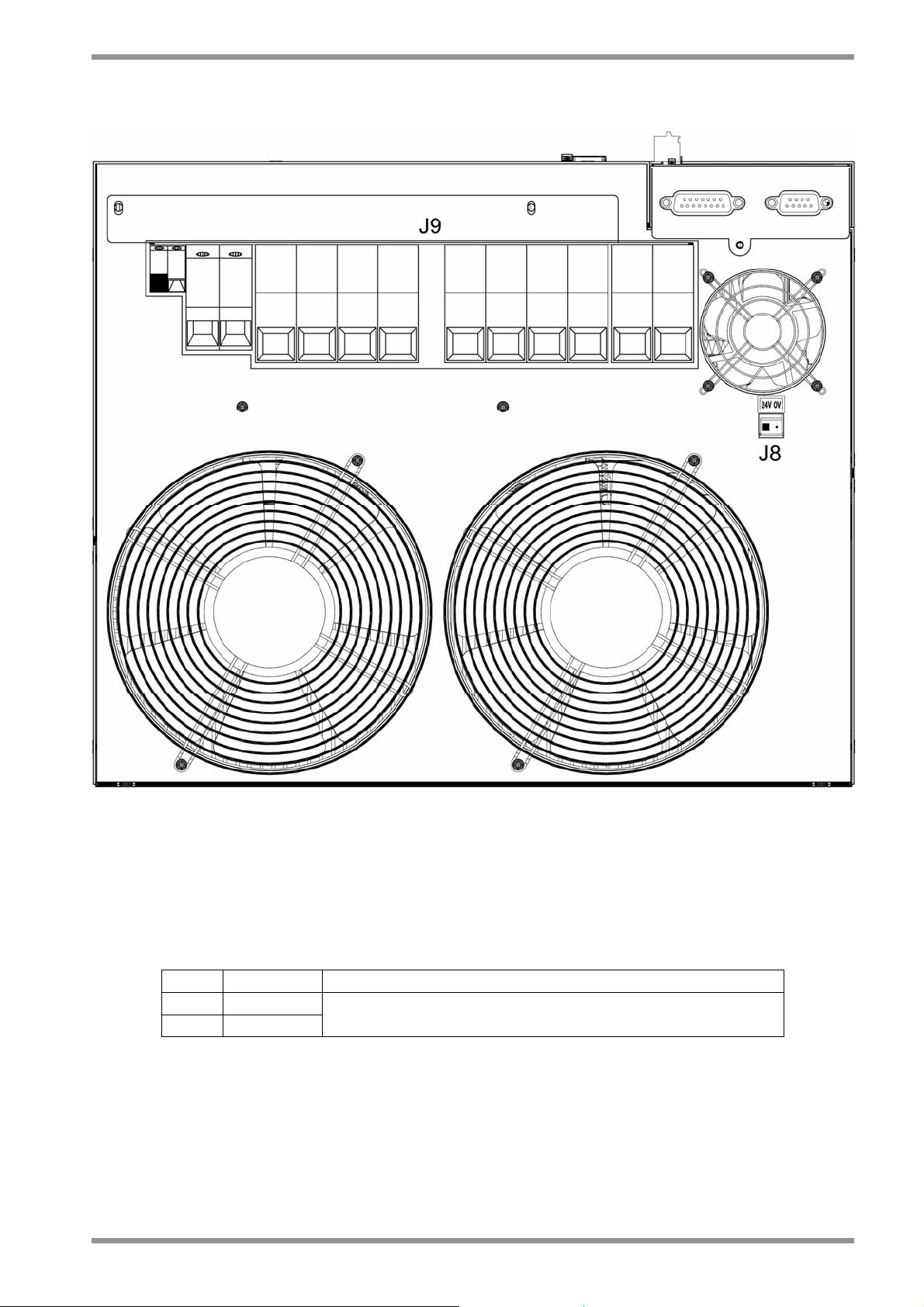
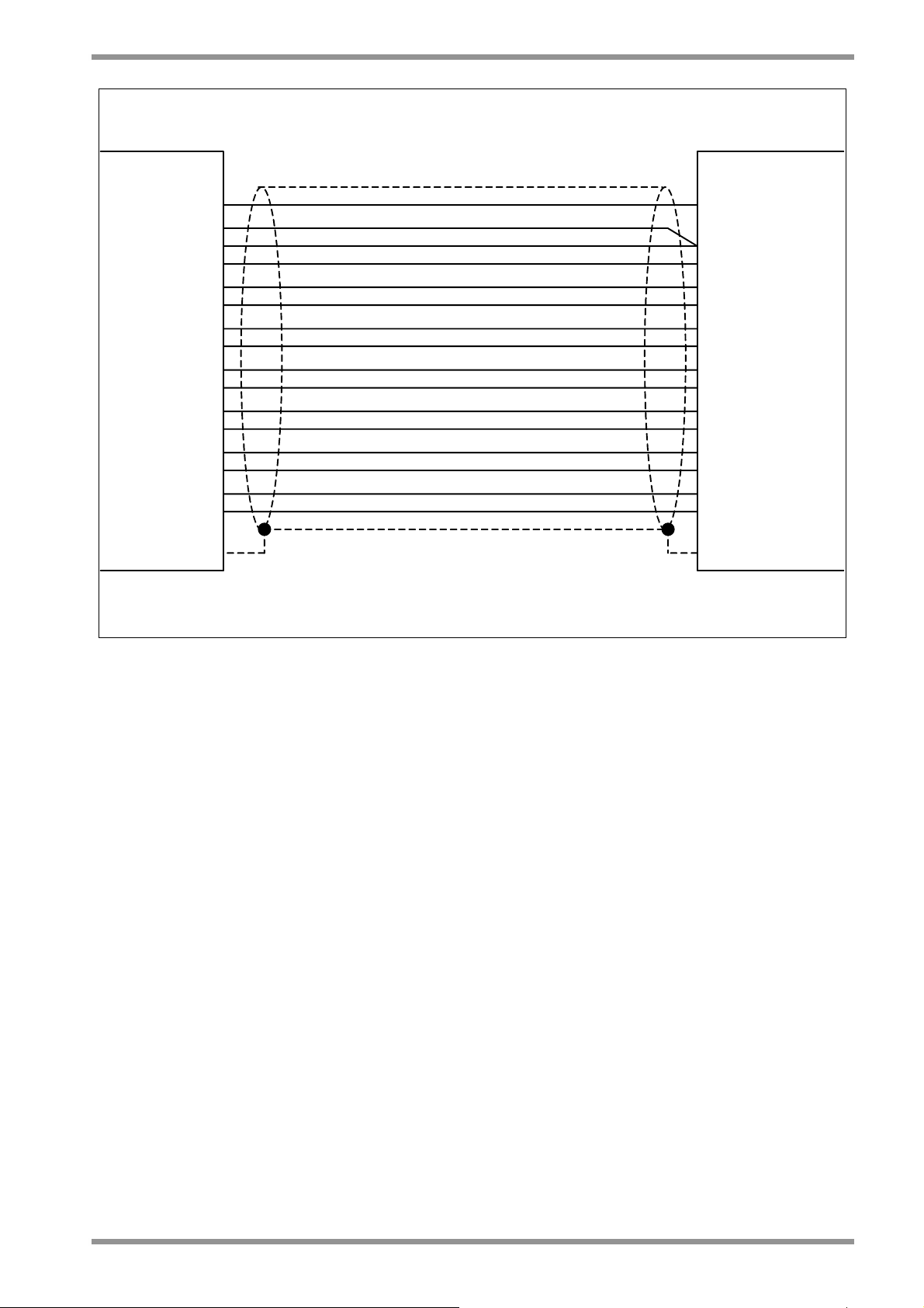
Fig. 2.14 – Resolver connections
DS2000 USER’S MANUAL (rev.C)
Page 59

SECTION TWO – WIRING AND INSTALLATION
2.11.3 MOTOR CONNECTION
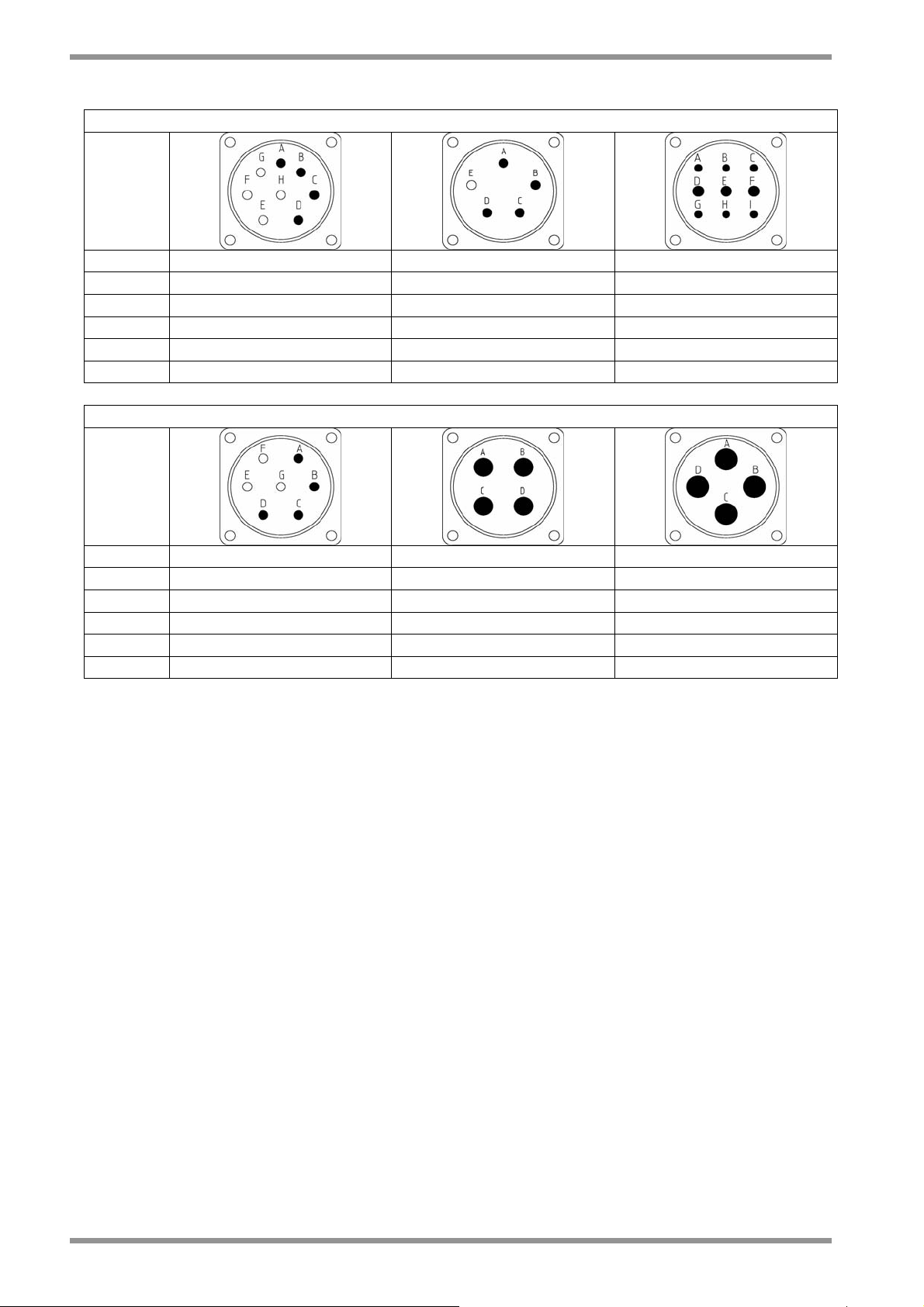
2.11.3.1 FAS T/FAS K/FAS N/FAS Y/FAE CONNECTION
MOTOR RESOLVER CONNECTOR
SIGNAL
TYPE
2.31
COS- E 2
COS+ C 1
SHIELD S 3
SEN- H 12
SEN+ G 11
PTC_MOTOR N 8
10kHz- B 7
PTC_MOTOR A 9
10kHz+ D 10
Tab. 2.22 – Resolver connectors
MOTOR ENCODER CONNECTOR
SIGNAL
TYPE
+5V A
0V B and V
W- C
W+ D
V+ E
V- F
A+ G
A- H
C+ J
C- K
U+ L
U- M
B- N
B+ P
PTC_MOTOR R
Tab. 2.23 – Encoder connector
DS2000 USER’S MANUAL (rev.C)
Page 60
2.32
SECTION TWO – WIRING AND INSTALLATION
MOTOR POWER CONNECTOR
SIGNAL
TYPE
U A A D
V B B E
W C C F
GND D D G
PTC - - H
PTC - - I
MOTOR POWER CONNECTOR
SIGNAL
TYPE
U A A A
V B B B
W C C C
GND D D D
PTC - - PTC - - -
Tab. 2.24 – Power connectors
DS2000 USER’S MANUAL (rev.C)
Page 61

SECTION TWO – WIRING AND INSTALLATION
2.33
2.11.3.2
G MOTOR CONNECTION
To standardize the resolver connection it is recommended for the new applications to use
the new resolver connection scheme of Tab.2.25A.
RESOLVER CONNECTION
Drive resolver connector
Pin No.
Name Pin name
Motor resolver connector
on G motor
Pin No.
1 ■ COS+ S2 3
2 COS- S4 4
3 SHIELD
4 SEN+ S1 1
5 SEN- S3 2
6 PTC_MOTOR THERM 1 5
7 10kHz- R2 8
8 PTC_MOTOR THERM 2 6
9 10kHz+ R1 7
Tab.2.25A – New resolver connection scheme
The old resolver connection scheme shown in the previous revisions of this Manual and
reprinted in Tab. 2.25B is still valid.
CAUTION: It is recommended not to change the old connections in case of retrofitting
motors or drives.
RESOLVER CONNECTION
Drive resolver connector
Pin No.
Name Pin Name on
Motor resolver connector
G motor
Pin No.
1 ■ COS+ S4 4
2 COS- S2 3
3 SHIELD
4 SEN+ S3 2
5 SEN- S1 1
6 PTC_MOTOR THERM 1 5
7 10kHz- R2 8
8 PTC_MOTOR THERM 2 6
9 10kHz+ R1 7
Tab.2.25B – Old resolver connection scheme
DS2000 USER’S MANUAL (rev.C)
Page 62

2.34
SECTION TWO – WIRING AND INSTALLATION
The ground (pin 3, drive side) has to be connected to the motor connector housing.
Several motor G have as standard a NTC for thermal feedback, the DS2000 can manage
PTC sensor or NTC sensor without any hardware change (see Section 6 for additional
data).
The resolver is looked mechanically: the customer has to perform the AUTOPHASING
with the drive utilities, checking that the value for the APHAPOS parameter is
–209 (±5Units) for 8 poles motor with 2 poles resolver or 45 (±5Units) for 12 poles motor
with 2 poles resolver (see Section 6 for additional informations).
MOTOR POWER CONNECTOR
DS2000
GND GND GND GND
U 2 U U
V 4 V V
W 1 W W
Tab. 2.26 – Power connector
DS2000 USER’S MANUAL (rev.C)
Page 63

SECTION TWO – WIRING AND INSTALLATION
2.35
2.12 DRIVE STARTING SEQUENCE
In order to properly power and enable DS2000 “The Motion Solution” series drives, it is
necessary to follow a start-up sequence, in which the minimum times to fall within are
indicated in order to allow the internal circuits to reach the operating voltage levels and to
make the internal devices ready for enabling.
The chart here below summarizes the start-up sequence and describes the possible reasons
for delays:
• t
Time delay required for the following operations:
1
Switching on of the 24V power supplier and input voltages stabilization
Program loading and logic circuits initialisation
Internal protections check carried out by the internal microprocessor
• t
Reset pulse to allow the reading of reference voltages, as well as the internal offsets
2
initialisation with already stabilized voltages.
Time needed by the drive to allow the program start-up after the reset.
• t
3
• t
Charge time of DC BUS capacitors determined by the soft-start circuit and DC BUS
4
voltage stabilization in order to avoid start-up self induction currents
• t
Time for DRIVE OK acquisition by the control
5
• t
Time to allow the Drive to reach the torque and to check the proper operation of power
6
stages.
The respect of the times indicated in Fig. 2.15 is important to avoid wrong FAULT indications
by the drive.
NOTE: The internal soft-start resistors are sized for a start-up occurring every 60 s. Lower
times cause an excessive stress and can cause the breakdown of such resistors.
DS2000 USER’S MANUAL (rev.C)
Page 64

2.36
SECTION TWO – WIRING AND INSTALLATION
2.13 STARTING SEQUENCE TIMES
t
≥ 3 s, t2 ≥ 100 ms., t3 ≥ 1 s, t4 = 3 s, t5 ≥ 100 ms., t6 ≥ 100 ms.
1
t
1
t
2
t
3
t
4
t
t
5
6
24Vdc
RESET
(restart)
pulse
230/460
V
ac
Three-phase
DRIVE OK
DRIVE
ENABLE
REFERENCE
ENABLE
Fig. 2.15 – Starting sequence times
NOTES:
• Reset pulse generates a complete initialization of the card with all the voltages already
stabilized; this allows a more careful reading of the voltages and a better compensation of
internal offsets.
• In case the auxiliary voltage (24V
) is missing, give the RESET pulse (for a time greater
dc
than 100 ms) after at least 3 seconds from the moment in which the drive is supplied by
three-phase voltage.
• RESET is necessary only after the first drive start-up or, in case of FAULT, to restore the
proper operation of drive.
• DRIVE OK signal depends upon the three-phase voltage presence, in order to allow a
quick and immediate enabling of motor torque.
DS2000 USER’S MANUAL (rev.C)
Page 65

SECTION TWO – WIRING AND INSTALLATION
2.37
2.14 DYNAMIC BRAKING
It is possible to execute a dynamic braking with the help of the motor torque, even in
emergency condition, if the drive is not in FAULT conditions: it is necessary to follow the
sequence times. At braking request, the REFERENCE ENABLE is removed and the motor
brakes with all the available torque.
• t
after 100 ms (this time can be increased in case load inertia is much bigger than motor
1
inertia) the DRIVE ENABLE can be removed
t
= 100 ms
1
Fig. 2.16 – Dynamic braking sequence times
DS2000 USER’S MANUAL (rev.C)
Page 66

2.38
SECTION TWO – WIRING AND INSTALLATION
2.15 POWER OFF
It is necessary to follow the power-off sequence times.
• t
after 100 ms (this time can be increased in case load inertia is much bigger than motor
1
inertia) the DRIVE ENABLE can be removed
• t
Three-phase input voltage release delayed time in order to avoid the undervoltage
2
FAULT.
• t
DC BUS discharge time
3
t
= 100 ms, t2 = 15 ms, t3 = 6 min. (to access the drive).
1
t
1
t
2
t
3
Fig. 2.17 – Power-off sequence times
REFERENCE
ENABLE
DRIVE
ENABLE
230/460
V
ac
Three-phase
DS2000 USER’S MANUAL (rev.C)
Page 67

SECTION TWO – WIRING AND INSTALLATION
2.39
2.16 MECHANICAL BRAKING
The FASTACT series motors have an optional electromagnetic brake with pressure springs
to be supplied with 24 V
CAUTION: the brake must be used only for standing (with motor at standstill). The use of this
brake for dynamic braking seriously damages the brake and reduces the braking torque.
Note 1: t
≥ 300 ms, t2 = application depending, t3 = 100 ms, t4 ≥ 200 ms
1
Note 2: For FASTACT motors, size 3 and size 4, t
t
1
nominal voltage (24 to 26 Vdc) at the motor terminal.
dc
≥ 1000 ms
1
t
t
2
t
3
4
ON
OFF
ON
OFF
RELEASE
CLAMP
0V
0 rpm
DRIVE
ENABLE
24V BRAKE
POWER SUPPLY
BRAKE
REFERENCE
ENABLE
MOTOR
SPEED
Fig. 2.18 – Mechanical braking sequence times
DS2000 USER’S MANUAL (rev.C)
Page 68

2.40
SECTION TWO – WIRING AND INSTALLATION
THIS PAGE INTENTIONALLY BLANK
DS2000 USER’S MANUAL (rev.C)
Page 69

SECTION THREE – ELECTROMAGNETIC COMPATIBILITY (EMC)
3.1
3. ELECTROMAGNETIC COMPATIBILITY (EMC)
3.1 INTRODUCTION
In this section are described the recommended drive installation procedure following EMC
standards. EMC filters are described in the 3.3 par. and the grounding and screening in the
3.4 par. and following. The installer of the drive is responsible for ensuring compliance with
the EMC regulations that apply where the drive is to be used.
3.2 EUROPEAN DIRECTIVE (89/336/EEC)
Compliance with the European Directive 89/336/EEC is required for all electric and electronic
products brought onto the European market after December 31st, 1995.
DS2000 drives meet the following EMC product standard related to the Directive:
EN 61800-3:1996 and EN 61800-3/A11:2000: "Adjustable speed electrical power drive
systems. Part 3: EMC product standard including specific test methods".
Second environment (industrial) compatibility levels.
Tests have been made in an independent test house.
3.3 FILTERS
3.3.1 FILTER TYPES
Trade-mark
Schaffner
FN2070-3-06
Schaffner
FN 258-7/07
Schaffner
FN 258-16/07
Schaffner
FN 258-30/07
Schaffner
FN 258-42/07
Schaffner
FN 258-55/07
Schaffner
FN 258-100/35
Rated current [A]
at 50°C (40°C)
(3) 250 24Vdc input
7 (8.4) 3x480
16 (19.2) 3x480 DS2000 14/42
30 (36) 3x480
42 (50.4) 3x480 DS2000 50/140
55 (66) 3x480 DS2000 60/180
100 (113) 3x480 DS2000 100/300
Max Voltage [Vac]
at 50°C
Drive type / input
DS2000 3/9
DS2000 4/12
DS2000 6/15
DS2000 8/22
DS2000 20/45
DS2000 25/70
DS2000 30/90
Tab. 3.1 – Filter types
DS2000 USER’S MANUAL (rev.C)
Page 70

3.2
SECTION THREE – ELECTROMAGNETIC COMPATIBILITY (EMC)
3.3.2 FILTER SIZING
The filter/drive coupling in the previous table is a standard application coupling. The filter
can be undersized according to the rms input current of the actual application. This should
be done not only because, as a mat-ter of fact, undersizing the filter means less money, but
because the undersized filter provides better performance to EMC.
3.3.3 FILTER DIMENSIONS
Top View
Side View
Trade-mark
Schaffner
FN2070-3-06*
Schaffner
FN 250-6/07*
Schaffner
FN 250-12/07*
Schaffner
FN 258-7/07
Schaffner
FN 258-16/07
Schaffner
FN 258-30/07
Schaffner
FN 258-42/07
Schaffner
FN 258-55/07
Schaffner
FN 258-75/34
Schaffner
FN 258-100/35
L1 L2 L3 L4 L5 L6 L7
85 75 54 0 65 40.3 faston 0.25
85 75 54 0 65 30 300 0.24
85 75 54 0 65 40 300 0.31
255 240 50 25
305 290 55 30
335 320 60 35 305 150 400 1.8
329 314 70 45 300 185 500 2.8
329 314 80 55 300 185 500 3.1
329 314 80 55 300 220
379
±1.5
364
Dimensions [mm]
90
±0.8
65
225
±0.8
275
±0.8
350
±1.2
126
±0.8
142
±0.8
220
±1.5
300 1.1
300 1.7
Terminal
block
Terminal
block
* = the FN2070-3-06 filter have faston at both sides
* = the FN250-6/07 filter have wiring leads (length=300mm) at both sides
* = the FN250-12/07 filter have wiring leads (length=300mm) at both sides
Weight
[kg]
4
5.5
Tab. 3.2 – Filter dimensions
DS2000 USER’S MANUAL (rev.C)
Page 71

SECTION THREE – ELECTROMAGNETIC COMPATIBILITY (EMC)
3.3.4 FILTER INSTALLATION
The filter must be mounted on the same drive panel.
CAUTION: leave a clear space at least 60mm around the filter for air circulation when the
cabinet does not have forced ventilation.
The filter must be connected as close as possible to the cabinet input. If the separation
between filter and drive exceeds around 30 cm (1 ft.) then a shielded cable should be used
for the RF connection between filter and drive.
NOTE: when mounting the drive and the filter to the panel, it is essential that any paint or
other covering material be removed before mounting the drive and the filter.
The maximum torque of mounting screws at terminal block is as follows:
FILTER Max torque
FN 258 - 7/07 0.8 Nm
FN 258 - 16/07 0.8 Nm
FN 258 - 30/07 1.8 Nm
FN 258 - 42/07 1.8 Nm
FN 258 - 55/07 3.0 Nm
FN 258 - 75/34 3.0 Nm
FN 258 - 100/35 4.0 Nm
3.3
Tab. 3.3 – Maximum torque of mounting screws at terminal block
WARNING: the filter can produce high leakage currents (see Filter Data Sheets)
WARNING: the filter must be connected to ground before connecting the supply
WARNING: High Voltage - Discharge time approx. 10 seconds
DS2000 USER’S MANUAL (rev.C)
Page 72

3.4
SECTION THREE – ELECTROMAGNETIC COMPATIBILITY (EMC)
3.4 WIRING AND GROUNDING
All the following cables must be shielded, with 85% minimum shielding coverage:
Power - Power motor cable
- External recovery resistor cable
- DC-BUS cable
Signal - Encoder cable (see Fig. 3.1)
- Resolver cable (see Fig. 3.1)
- RS485 / CAN BUS cable
- J2A, J2B, J2C cable
- 24V power supply cable
- Restart Interlock cable
- 24V fans cable (only size E)
Fig. 3.1 – Grounding of shield to connectors at motor side
NOTES:
If a power terminal board is used at motor side, the shield must be RF connected to a
metallic PG gland.
The shields of the cables must be connected at both ends to the proper housing via full
circumferential bond to metallic connectors or hose clamps.
In case of Sub-D connector, cable shield must be grounded to the metallic hood.
When there is not metallic connector at drive side, a kit with stand-off, screws and
metallic hose clamps is provided. The shield of the cable must be uncovered from
insulation coating and RF connected to the stand-off through the metallic hose clamp,
as in Fig.3.2.
Fig. 3.2 – Grounding of shield without metallic connector
DS2000 USER’S MANUAL (rev.C)
Page 73

SECTION THREE – ELECTROMAGNETIC COMPATIBILITY (EMC)
3.5
Fig. 3.3 – A and B size connections drive side
Cable 1 = J2A, J2B, J2C
Cable 2 = Motor power
Cable 3 = Recovery resistor and –AT
Cable 4 = Safety - Restart Interlock (optional)
NOTE:Unshielded (three-phase power supply) and Sub-D cables are not shown in the figure.
DS2000 USER’S MANUAL (rev.C)
Page 74

3.6
SECTION THREE – ELECTROMAGNETIC COMPATIBILITY (EMC)
Fig. 3.4 – C size connections drive side
Cable 1 = J2A, J2B, J2C
Cable 2 = Motor power
Cable 3 = Recovery resistor and +/-AT
Cable 4 = Safety - Restart Interlock (optional)
NOTE:Unshielded (three-phase power supply) and Sub-D cables are not shown in the figure.
DS2000 USER’S MANUAL (rev.C)
Page 75

SECTION THREE – ELECTROMAGNETIC COMPATIBILITY (EMC)
3.7
Fig. 3.5 – D size connections drive side
Cable 1 = J2A, J2B, J2C
Cable 2 = Motor power and +/-AT
Cable 3 = Recovery resistor
Cable 4 = Safety - Restart Interlock (optional)
NOTE:Unshielded (three-phase power supply) and Sub-D cables are not shown in the figure.
DS2000 USER’S MANUAL (rev.C)
Page 76

3.8
SECTION THREE – ELECTROMAGNETIC COMPATIBILITY (EMC)
Fig. 3.5.1 – E size connections drive side
Cable 1 = J2A, J2B, J2C
Cable 2 = Motor power and +/-AT
Cable 3 = Recovery resistor
Cable 4 = Safety - Restart Interlock (optional)
NOTE:Unshielded (three-phase power supply) and Sub-D cables are not shown in the figure.
DS2000 USER’S MANUAL (rev.C)
Page 77

SECTION THREE – ELECTROMAGNETIC COMPATIBILITY (EMC)
3.9
It is not necessary to shield the input power wires. A shielded cable should be used between
filter and drive if the separation exceeds 30 cm.
The shields of cables inside the cabinet must be 360° clamped to the cabinet wall
(see Fig. 3.6).
Fig. 3.6 – Backpanel connection
The power cables must be kept away from signal cables by at least 30 cm.
When the power cables cross the signal cables, this intersection must be done with angles as
near to 90° as possible.
The crossing of the cabinet should be accomplished with a low impedance (RF) connection
between cable shield and enclosure. If a connector is not involved, the shortest practical
lengths of connecting strap should be used (see Fig.3.7).
Fig. 3.7 – Partition penetration
DS2000 USER’S MANUAL (rev.C)
Page 78

3.10
SECTION THREE – ELECTROMAGNETIC COMPATIBILITY (EMC)
3.5 RECOVERY RESISTOR
To meet the EMC Directive the enclosures containing the recovery resistors must be
conductive. The recovery resistor cable must be shielded and the shield must be 360°
clamped at both sides.
NOTE: before mounting the enclosure of recovery resistor to the panel make sure that any
paint or other covering material be removed.
3.6 SCREENING
To effectively screening the system all the single screens (CNC, electronic cabinet, machine,
motor housing, cables) must be connected together to effectively form one screen.
3.7 SAFETY ASPECTS
Noise suppression of motor and drive systems involves consideration of the grounding
system, and its effective-ness at high frequencies. It should not be forgotten the safety aspect
and that the safety must take priority over EMC.
To reduce the radiated emissions, the use of capacitance to ground is very effective. In fact,
Schaffner filters have Y-type capacitors near the input power supply connector.
These capacitors leak current from phase to ground; this can be in the order of hundreds of
milliamperes.
WARNING: appropriate safety measures should be taken to ensure that this potentially
dangerous current flows to ground.
CAUTION: it is recommended to disconnect the drive and the EMC filters to carry out the AC
Voltage Tests of EN 60204-1:1997, par.19.4, in order to not damage the Y-type capacitors
between phases and ground. Moreover the DC voltage dielectric test required by
EN 50178:1997, product family standard, has been carried out in factory as a routine test.
The DC Insulation Resistance Tests of EN 60204-1:1997, par.19.3, may be carried out
without disconnecting the drive and the EMC filters.
DS2000 USER’S MANUAL (rev.C)
Page 79

SECTION FOUR – STARTING
4.1
4. STARTING
4.1 INTRODUCTION
The purpose of this section is to provide a series of suggestions to make the first start-up of a
DS2000 drive, connected to a Moog motor, easier.
All the information hereinafter are easy and descriptive, in order to be clearly understood
even by personnel not skilled in servosystems installation.
Please, refer to the previous sections to search for any eventual missing information on cable
connections.
Please, refer to Section 6 for a detailed description of motor and drive parameters.
DS2000 USER’S MANUAL (rev.C)
Page 80

4.2
SECTION FOUR – STARTING
4.2 DRIVE SETTING UP INFORMATION
To set a drive it is necessary to search for some information, unless Moog already set them
upon customer’s request. It is necessary to know:
a) Motor settings
1) Number of motor poles
2) Motor max current
3) Motor voltage rating
4) Motor nominal speed
5) Motor BEFM (at 1000 rpm)
6) Motor resistance
7) Motor inductance
8) ID magnetization current (only for vectorial control asynchronous motors)
9) SG slip (only for vectorial control asynchronous motors)
10) Motor thermal feedback (PTC or NTC)
11) Resolver or Encoder feedback
12) Starting Speed for FASG algorithm (required only for G motor at high speed)
13) Max phase angle for FASG algorithm (required only for G motor at high speed)
14) Number of encoder pulses or number of resolver poles
15) Number of pulses per electrical revolution needed by the CNC
(for resolver interface only)
16) Zero marker width (for resolver interface only)
NOTE: It is not possible to modify the number of output pulses and the zero marker width
using the Encoder feedback. Such function is available only using resolver feedback.
b) Drive settings
1) Remote control for drive enable
2) Max speed requested to motor
3) Max current supplied by the drive
4) Speed or torque control; set speed control mode when drive is used for tests
5) ACC/DEC value (only in speed control mode; function is disabled when set to 0)
6) Reference analog control
7) Digital (managed by drive) or analog (managed by control) current (torque) limit
8) VKI and VKP (integral and proportional gain) according to the applied load
9) LPF filter on error and reference, and Notch
10) Anti Free wheeling function if required (perform a velocity stop if motor is in OVT,
drive is in OVT, mains is lost)
11) Protection on RR parameters if required
12) Drive I2T protection parameters if required
13) Dead band amplitude on analog references if required
CAUTION: The installation can be carried out also without some of the above information
because it is possible to enter them later using the built-in keypad or the WinDrive GUI
program.
DS2000 USER’S MANUAL (rev.C)
Page 81

SECTION FOUR – STARTING
4.3
NOTE:
The display shows immediate information about motor and drive status by means of lighting:
• The display is lit with full light if no FAULTS are detected
• The display is lit with reduced intensity in case of FAULTS (refer to Section 6)
4.3 FIRST START-UP (ON TEST BENCH, FOR TESTING PURPOSES)
First, connect the power supply (both in case of 24 Volt and alternating voltage option).
Connect the feedback (resolver or encoder) and motor power cable, to also control the
motion.
Power the drive without giving the DRIVE ENABLE and the REFERENCE ENABLE.
The display must be lit, it is to say not in alarm condition; otherwise, check alarms in the
appropriate menu.
Hand-rotate the motor shaft in order to check the proper reading of feedback information by
the drive and eventually check the motor speed reading following the instructions contained
in the Display menu described in Section 6.
To control also motor motion, supply the three-phase alternating voltage and give the DRIVE
ENABLE and the REFERENCE ENABLE. It will be possible to move the motor with the given
settings if connections are not wrong.
If movements are missing, refer to Section 7 (Troubleshooting).
4.3.1 FEEDBACK CONNECTION (ENCODER OR RESOLVER)
Feedback connection must always be made according to the specification in section 2 even
if drive power supply is made only for testing purposes.
Inadequate connections (i.e.: unshielded cables) cause feedback and motor control errors.
4.3.2 “TEMPORARY” OR TEST POWER WIRING
In order to carry out a drive test, it is possible to supply the DS2000 with power in two ways:
• By a 24 VOLT, 1.5 A source
• By an alternating v oltage (both s ingle-phas e and three-phase) between 120 and 510 V
(if the drive is supplied with a voltage lower than 120V
it is necessary to supply a 24
ac
Vdc auxiliary voltage, as the internal power supplier cannot properly work).
The 24 Volt solution allows a safe setting and testing the signal connections without
dangerous voltages.
NOTE: it is not possible to enable the output stages when DC BUS is not supplied with
power giving a DRIVE ENABLE signal, otherwise the drive will signal a DC BUS
UNDERVOLTAGE FAULT condition.
When drive is connected for test purposes only, it is possible to use a common, unshielded
cable, both for power input and to connect the motor power.
ac
DS2000 USER’S MANUAL (rev.C)
Page 82

4.4
SECTION FOUR – STARTING
4.3.3 TEMPORARY CONNECTIONS
The cross section of the cable connecting the drive to power line and to motor can be lower
than the one recommended for drive size if drive peak current will not be supplied and the
connection is made only for setting and checking purposes, and the motor is used at low
speed and reduced torque.
Even if a soft-start circuit is always present and active on each drive, it is recommended to
protect the power input line with fuses or a circuit breaker; anyway, the current absorbed by
the drive during the soft-start is limited by a resistor.
NOTE: Remember to wait at least 60 s between two power switches in order to allow the
internal soft-start resistor to properly dissipate the accumulated energy.
4.4 CONFIGURATION FOR INSTALLATION IN ELECTRICAL CABINET
Additional settings for installation in the electrical cabinet concern the torque remote enable
setting in order to allow the CNC to control torque supply, when requested, giving the DRIVE
ENABLE hardware signal.
Remember to eliminate the settings used on test bench that eventually limit performances.
DS2000 USER’S MANUAL (rev.C)
Page 83

SECTION FIVE – COMPONENT DESCRIPTION
5. COMPONENT DESCRIPTION
5.1 INTRODUCTION
This section provides descriptions for the DS2000 Series Drives.
5.1
DS2000 USER’S MANUAL (rev.C)
Page 84

5.2
SECTION FIVE – COMPONENT DESCRIPTION
5.2 HIGH POWER INPUT SECTION
The high power supply section has the following features:
• Three Phase AC Operation
• Direct Off-Line 230 V
• Soft-start (AC Inrush Current Limiting)
• Input Varistor Transient Protection
• Drive Ready Relay (DROK)
• Provision for External Recovery Resistor
• Integral Heat Sink and Cooling Fans
• Input 24V Logic Backup
• Internal inductance only for size E
These features are described in the next sections.
WARNING: High Voltage. Bus Bar’s can have voltage ≥810V
(capacitive voltage). Discharge Time approx. 6 Minutes.
WARNING: High Voltage. The recovery resistor is connected to the Bus Bar’s and can have
voltage ≥810Vdc.
WARNING: do not touch recovery resistor during operation to avoid scalds.
5.2.1 CIRCUIT DESCRIPTION
The high power supply consists of four functional blocks:
• High voltage rectification and filtering
• Soft-start of AC mains power-on
• Low voltage control power supply
• Recovery circuit
to 460V
rms
±10% Operation
rms
even after switching off
dc
DS2000 USER’S MANUAL (rev.C)
Page 85

SECTION FIVE – COMPONENT DESCRIPTION
5.2.1.1 HIGH VOLTAGE RECTIFICATION AND FILTERING
The AC mains input is rectified by a three-phase diode bridge and filtered by a bank of
electrolytic capacitors to generate the internal DC BUS. This high power DC supply is
unregulated and will vary in direct proportion with the AC mains input voltage magnitude.
Inductance only for size E
5.3
Fig. 5.1 – Power input section
5.2.1.2 SOFT START
Soft start is used to limit the inrush current to the DC BUS capacitor bank on application of
AC mains power. This is intended to prevent blowing of line fuses on power-up.
The switch is a relay on DS2000 Series up to size B. It is an SCR on the other sizes.
The soft start switch will close when the monitoring circuit and associated control software
determines that the high-voltage DC BUS has charged up and the DC BUS is at steady
state.
If the DC BUS voltage suddenly changes at drive enable, it is possible that troubles are
present on the three-phase power line (interrupted fuse, missing connection, or
inadequate power supply) and the drive gives an error signal.
5.2.1.3 LOW VOLTAGE CONTROL POWER SUPPLY
Control power for the logic circuits is generated by a DC/DC converter, which provides
control-circuitry power that is isolated from the mains input. This control voltage also
powers the cooling fans.
DS2000 USER’S MANUAL (rev.C)
Page 86

5.4
SECTION FIVE – COMPONENT DESCRIPTION
5.2.1.4 RECOVERY CIRCUIT
Rapid motor deceleration or an overhauling load creates a situation in which energy is
returned back into the DC BUS. This recovery energy will charge up the power supply DC
BUS capacitors. To prevent capacitor overvoltage, a shunt regulator circuit senses when
the DC BUS voltage exceeds the recovery cut-in voltage and via a recovery IGBT,
switches a recovery resistor across the DC BUS to dissipate the recovery energy.
Hysteresis in the circuit keeps the recovery circuit active until the DC BUS voltage is
reduced below the recovery cutout voltage.
The drive controls the braking circuit thresholds according to the different power supply
voltages with no need for hardware calibration or setting.
WARNING: High Voltage. The recovery resistor is connected to the Bus Bar’s and can
have voltage ≥810Vdc.
WARNING: do not touch recovery resistor during operation to avoid scalds.
CAUTION: In applications where the working cycle implies decelerations with high inertial
loads, from high velocity in very short deceleration time, it is necessary to properly size
the recovery resistor. In these cases, please contact Moog Service Centers.
DS2000 USER’S MANUAL (rev.C)
Page 87

SECTION FIVE – COMPONENT DESCRIPTION
5.2.1.4.1 RECOVERY RESISTOR PROTECTION
In order to thermally protect the recovery resistor a set of parameters has been provided
in the menu. These parameters are:
• Resistor (RECOVERY RESIST. RESREC)
• Power (RECOVERY RESIST. POWER)
• And recovery coefficient (RECOVERY RESIST. COEFF)
The parameters to be set with the standard recovery resistors are shown in tab 5.1.
Drive
Size
Max
peak
Current [A]
Resistor
Value [Ω]
Resistor
Power [W]
Coeff.
Value
3/9 10.0 75 (ext.) 100 71
4/12 10.0 75 (ext.) 100 71
6/15 14.7 51 (ext.) 200 53
8/22 14.7 51 (ext.) 200 53
14/42 22.7 33 (ext.) 250 43
20/45 62.5 12 (ext.) 370 74
25/70 62.5 12 (ext.) 370 74
30/90 62.5 12 (ext.) 370 74
50/140 75.0 10 (ext.) 750 21
60/180 75.0 10 (ext.) 750 21
100/300 192.3 3.9 (ext.) 1000 17
3/9 9.1 82 (int.) 150 84
4/12 9.1 82 (int.) 150 84
6/15 13.4 56 (int.) 150 78
5.5
Tab. 5.1 – Setting protection coefficient of recovery resistor
With 230 Vac mains power supply a more efficient series of recovery resistors can be used.
These optional resistors with the appropriate parameters are shown in tab 5.2.
Drive
Size
Max
peak
Current [A]
Resistor
Value [Ω]
Resistor
Power [W]
Coeff.
Value
3/9 10.0 47 (ext.) 100 69
4/12 10.0 47 (ext.) 100 69
6/15 14.7 33 (ext.) 250 45
8/22 14.7 33 (ext.) 250 45
14/42 22.7 22 (ext.) 240 69
20/45 62.5 6.8 (ext.) 370 63
25/70 62.5 6.8 (ext.) 370 63
30/90 62.5 6.8 (ext.) 370 63
50/140 75.0 5.6 (ext.) 750 19
60/180 75.0 5.6 (ext.) 750 19
100/300 192.3 2.2 (ext.) 1000 17
3/9 9.1 47 (int.) 150 87
4/12 9.1 47 (int.) 150 87
6/15 13.4 33 (int.) 150 80
Tab. 5.2 – Setting protection coefficient of recovery resistor
DS2000 USER’S MANUAL (rev.C)
Page 88

5.6
SECTION FIVE – COMPONENT DESCRIPTION
In applications where high or continuous recovery energy is anticipated, consult your
Moog sales representative, requesting an application review. In case of different
resistors, different parameters must be set.
5.3 HIGH POWER OUTPUT SECTION
The high power supply section has the following features:
• Three-phase output bridge
• PWM technology
• 10kHz switching frequency
5.3.1 CIRCUIT DESCRIPTION
5.3.1.1 HIGH POWER OUTPUT SECTION
The direct current energy available on the DC BUS is converted into current supplied to
the motor by an output three-phase bridge formed by IGBT.
By means of PWM technology the output currents are generated with a high energy
efficiency ratio.
The word PWM (Pulse Width Modulation) identifies a way of controlling the power devices
in order to avoid any linear conduction status, and have only conduction and cut off status,
to reduce the power dissipation. This way allows a high efficiency in energy conversion
and, as a consequence, reduced energy losses.
The 10kHz switching frequency allows to limit the heating effects per current ripple inside
the motor.
Each IGBT is individually protected from short circuit and overload and its protection is
directly managed by the control card.
Fig. 5.2 – Power output section
DS2000 USER’S MANUAL (rev.C)
Page 89

SECTION FIVE – COMPONENT DESCRIPTION
5.4 CONTROL SECTION
The Control section has the following features:
• Speed loop
• Current loop
• Low-pass filters (LPF)
• Notch Filter
5.4.1 CIRCUIT DESCRIPTION
The Control Circuit consist of several functional blocks:
• Motor Feedback (size, voltage, rpm)
• Speed Feedback
• Speed loop (VKP, VKI)
• LPF Filter (frequency)
• Notch Filter ( frequency, band, gain)
• Current Feedback
• Current Loop (Rw, Lw, E1000, ID, SG)
• PWM Amplifier (limit)
• Position Feedback (APHAPOS)
5.7
Fig. 5.3 – Servosystem block diagram
5.4.1.1 HIGH POWER OUTPUT SECTION
The drive checks the current angular position in order to always keep a 90° angle
between the magnetic field generated by currents and the one generated by magnets on
the motor rotor.
The motor position is given by the feedback signals coming from the encoder or from the
resolver through an appropriate processing.
According to the information existing in the setting loop, the drive processes the
information concerning current width, frequency and angular position, and properly
commands the IGBT to supply the currents.
The current feedback is obtained by means of Hall sensors placed on U and V motor
phases.
The position feedback can be both the resolver and the encoder; inside the drive the two
signals are managed by two separate circuits in order to obtain the same final information
for the speed loop.
DS2000 USER’S MANUAL (rev.C)
Page 90

5.8
SECTION FIVE – COMPONENT DESCRIPTION
LPF filters on the reference and on the speed error allow to adapt the servosystem (drive
+ motor) pass band to the application characteristics.
The Notch filter allows to eliminate or reduce any eventual oscillation on the machine
mechanics be-cause of the limited rigidity of the motor transmission parts (mechanical
transmissions, belts, etc.), specially in presence of high inertia ratios between motor and
load (mismatching load condition).
5.4.1.1.1 LOW AND HIGH SPEED OPERATION
Current control loop has two different working conditions: Low speed and High speed.
The difference is determined by motor voltage with respect to the available output
voltage on motor phases.
At low speed, the voltage supplied by the drive is higher than the one generated by the
motor, and the field generated by current is in phase with the field generated by
magnets.
At high speed, the motor voltage can be compared to the voltage available from the
drive; the relevant phase between the magnetic fields is automatically changed in order
to keep such a voltage margin as to allow an optimal current adjustment.
This algorithm allows an optimal exploitation of motor characteristics, supplying the
same peak torque both at low and high speed, with a higher peak power available for
machinery motion.
It is also possible to wind the motors with a higher torque constant; thanks to this
feature, in many applications, it is possible to use a drive supplying a lower current to
obtain the same peak torque at motor output.
All the motors produced by Moog, are provided with this feature and give high
performances at high rotation speed.
An additional phase shift is given by the G motors Algorithm, suggested mainly for
motors having high poles number (8 or 12) and running at speed over 3000 rpm.
Standard Drive
Phase max V=1/2
Vbus
DS2000 Drive
Phase max V>1/2
Vbus
DS2000 USER’S MANUAL (rev.C)
Page 91

SECTION FIVE – COMPONENT DESCRIPTION
5.4.1.1.2 ENCODER/RESOLVER SIGNALS COHERENCE CONTROL
The drive carries out a control on the encoder high and low transition coherence and on
the resolver phases sequence.
By manually rotating the motor, with drive supplied only with 24 Vdc, it is possible to carry
out a control of the connection between feedback and drive; any eventual fault signal in
dicates feedback problems (see Section 7).
5.4.1.2 CONTROL LOOPS
5.4.1.2.1 CURRENT LOOP
• The current loop is based on a PI structure with motor electromotive force (B.E.M.F.)
compensation on speed variation.
• The implemented algorithms allow to adjust integral and proportional gains by
entering data via keyboard or Windrive GUI with no drive instruments or test bench
calibration.
• Only data concerning Electric Resistor (Rw), Motor inductance (Lw), and Motor
electromotive force (B.E.M.F.) are needed to adapt the current loop frequency
response to the motor characteristics.
• The electromotive force compensation allows the increase the peak current that can
be supplied at high speeds because the loop compensates the voltage associated to
the supplied current and to the current generated by motor, dephasing the currents
position.
• The loop structure also compensates the phase shift introduced by the current
sensors and by the interface circuits, allowing a null phase shift and a “flat” phase
response between 0 and approx. 800 Hz, independently of the controlled motor
model.
• The loop closing, at a frequency of 10 kHz, allows to dynamically compensate the
inductance, resistor, and electromotive force variation of the motor at load and motor
rotor angular position variation.
5.4.1.2.2 CURRENT LOOP OPTIMIZATION
The current loop optimization is automatically carried out by entering the motor physical
characteristics: Resistor, Inductance, and Electromotive Force.
Such data must be entered in physical units: the Resistor in Ohm, the Inductance in mH
(milliHenry) and the Electromotive Force in Volt at 1000 rpm.
The drive automatically adjusts the current loop gains and carries out the angular
correction as a function of the motor rotation speed and of the torque requested to
motor.
No other customer calibration is needed, except for entering the motor physical
parameters.
Note: If the output current at high speed (max working speed) is too high, it is possible
trying to reduce it, reducing the motor inductance value (-20 %) and reducing the motor
BEMF value; the reason is linked to the motor reluctance, that change in the motor
revolution
5.9
DS2000 USER’S MANUAL (rev.C)
Page 92

5.10
SECTION FIVE – COMPONENT DESCRIPTION
5.4.1.2.3 SPEED LOOP
• The speed loop has a simple PI structure.
• Through the KI and KP gains the servosystem response can be adapted to the
applied load.
• The control loop is closed with a frequency of 5 kHz.
• The pass band is internally limited via software at 400 Hz; the phase shift is missing
for the usable pass band.
• The loop allows the setting of the “higher frequency” of the pass band because it is
proportional to VKI (axis rigidity at low speed).
• The VKP value allows to control the oversho ot when set speed is reached
(higher gain,higher control)
• A low-pass filter of the second order is placed on the speed error to limit the
frequency response in case of device oscillation that cannot be compensated by
changing CNC or drive gains.
• System excessive gains can cause a reduction of the supplied torque due to the
excessive pass band and to the aliasing effect on the servo system main
frequencies.
5.4.1.2.4 SPEED LOOP OPTIMIZATION
The speed loop optimization is carried out adjusting VKI and VKP parameters, which
correspond, respectively, to the speed loop Integral and Proportional Gain, as well as
properly adjusting the filters, if necessary. It is possible to minimize the error acting on
VKI and VKP gains during the device operation thus obtaining the required response.
DS2000 USER’S MANUAL (rev.C)
Page 93

SECTION SIX – COMMANDS
6.1
6. COMMANDS
6.1 INTRODUCTION
The six keys on the drive front panel allow the visualization of the whole menu as well as the
relevant drive configuration. A further key allows the display contrast adjustment.
The keys can be divided according to their function:
• ENTER. This key allows to enter a menu and browse it. The variables scanning inside a
menu is recursive. In some cases, this key activates a routine function (i.e. inside the
“Utility” menu).
• < >. These keys allow the menu horizontal scrolling from right to left and vice versa.
• + -. These keys allow to increase and decrease a variable. Holding the key down approx.
5 s the fast forward starts.
• ESC. This key allows to go back inside the menu or terminate a function.
• ☼. Holding down the yellow key, it is possible to adjust the display contrast by means of
the + / - keys. In order to keep the setting, it is necessary to save the parameters before
switching off the drive.
Fig. 6.1 – DS2000 front panel
NOTES:
• First screen at drive start-up show you the DS2000 size. The DRIVE ENABLE and
REFERENCE ENABLE signals are shown in the start-up screen on the display by two
stylized letters: “D” and “R” respectively.
• The first menu level can be accessed pressing ENTER. The first level is characterized by
the two <> arrows which indicate the possibility of scrolling the menu from right to left. To
access the menu, press ENTER. To go to the following parameter, press ENTER or < and
> keys. The parameter scanning is recursive.
• To exit the menu, press ESC. Keep on pressing if the displayed parameter is not the first
item of the menu.
DS2000 USER’S MANUAL (rev.C)
Page 94

6.2
SECTION SIX – COMMANDS
• When the parameter to be modified is reached, press +/- to increase or decrease the
variables.
• At start-up, after a reset, or a saving of parameters, the drive is in “locked keyboard”
status in order to avoid parameters and system settings accidental modifications. To
modify parameters it is necessary to unlock the keyboard. To unlock the keyboard it is
necessary to activate the function “unlocked keyboard” inside the “Keyboard locked”
menu (see cap. 6.8).
• In order to save the modified parameters the function “Save Parameters” inside the “Utility
menu” should be used; the saving occurs only when drive is not enabled.
• In case of FAULT, the display light intensity is reduced.
• The main menu is not “circular”; when the bottom is reached, press ESC or < to go back.
The Enter button can be used to go forward the menu.
6.2 MOTOR PARAMETERS MENU
Fig. 6.2 – Motor parameters menu
DS2000 USER’S MANUAL (rev.C)
Page 95

SECTION SIX – COMMANDS
6.2.1 MOTOR PARAMETERS MENU DESCRIPTION
MOTOR PARAMETERS POLES=
Allowed values:
from 2 to 24 in 2 unit steps
MOTOR PARAMETERS SIZE=
Allowed values:
from 1.0 A to the peak current supplied by the drive in
100mA steps
MOTOR PARAMETERS VOLTAGE=
Allowed values:
• 230 V (for 230 V motors)
• 400 V (for 400/460 V)
MOTOR PARAMETERS SPEED=
Allowed values:
from 100 rpm to 9999 rpm in 10 rpm steps
MOTOR PARAMETERS BEMF=
Allowed values:
from 0 V to 750 V in 1 unit steps
MOTOR PARAMETERS Rw=
Allowed values:
from 0 Ω to 100 Ω in 0.1 unit steps
MOTOR PARAMETERS Lw=
Allowed values:
from 0 mH to 200 mH in 0.1 unit steps
Description: it indicates the number of motor poles
Note: set the values indicated on the nameplate of
the motor or refer to the data indicated on the motor
catalogue.
Description: it indicates the motor peak current value
Note: If this value is not available, it is possible to
obtain the peak current by means of the following
formula:
I
peak
where Tm is the max torque in Nm and Kt is the
motor torque constant in Nm/A
Description: it indicates the motor winding voltage
rating value
Note: set the values indicated on the nameplate of
the motor or refer to the data indicated on the motor
catalogue
Description: it indicates the nominal motor speed
Note: set the values indicated on the nameplate of
the motor or refer to the data indicated on the motor
catalogue
Description: it indicates the motor generated backelectromotive force value at 1000 rpm.
Note: the drive uses this information to optimize the
current loop as a function of the motor rotation
velocity. If this value is not available, it is possible to
obtain the BEMF by means of the following formula:
BEMF=K
where K
Description: it indicates the motor resistance value,
measured between phase and phase
Note: set the values indicated on the nameplate of
the motor or refer to the data indicated on the motor
catalogue. If this value is not available, it is possible
to obtain it using a multi-meter (set as an ohm-meter)
Description: it indicates the motor inductance value,
measured between phase and phase
Note: set the values indicated on the nameplate of
the motor or refer to the data indicated on the motor
catalogue. If this value is not available, it is possible
to obtain it using a multi-meter (set as an inductancemeter).
Attention: for G motors use the L
=1.41*Tm/Kt
*60.4
t
is the motor torque constant in Nm/A
t
value instead of L
q
6.3
tt
DS2000 USER’S MANUAL (rev.C)
Page 96

6.4
APHAPOS=
Allowed values:
from 0 to ±255 in 1 unit steps
MOTOR PARAMETERS ID=
Allowed values:
from 0 to the peak current supplied by the drive in
100mA steps
MOTOR PARAMETERS SG=
Allowed values:
from 0 to 100 in 0.1 unit steps
INI PHASE SHIFT=
Allowed values:
from 100 to max speed drive in 10 unit steps
MAX PHASE SHIFT=
Allowed values:
from 0 to 50 in 1 unit steps
PTC/NTC SEL.=
Allowed values:
• 0 (for PTC thermal feedback)
• 1 (for NTC thermal feedback)
ENCODER<>RESOLVER
Allowed values:
• ENCODER (for ENCODER feedback)
• RESOLVER (for RESOLVER feedback)
SECTION SIX – COMMANDS
Description: It indicates the phasing value correction
between the position feedback (resolver or encoder)
and the motor phases
Note: this value can be automatically modified by the
PHASING procedure.
Note: the APHAPOS value can be manually entered
by the keyboard without the PHASING procedure.
Note: the APHAPOS values follows:
• APHAPOS = 0 for FAS T, FAS N, FAS K motors
• APHAPOS = 125 only for FASK motor with 2
resolver poles
• APHAPOS = -209 for G 8 poles motor with 2
resolver poles
• APHAPOS = 45 for G 12 poles motor with 2
resolver poles
Description: it indicates the magnetization current
value when using an asynchronous motor in vector
control mode
Note: set the values indicated on the motor catalogue
Description: it indicates the slip frequency (gain)
value for asynchronous motors control working in
vector control mode
Note: set the values indicated on the motor
catalogue. If this value is not available, it is possible
to obtain it analyzing the response to transients
Description: it indicates the starting speed for the G
motors algorithm, to improve phase shift at high
speed mainly for motors having 8-12 poles and
rotating over 3000 rpm
Note: see related application notes for additional
details
Description: it indicates in electrical degrees the max
phase angle of the above algorithm
Note: see related application notes for additional
details
Description: Allow the selection between PTC or
NTC as thermal feedback
Note: set the thermal feedback according to motor
data
Description: it indicates the type of motor feedback
Note:
DS2000 USER’S MANUAL (rev.C)
Page 97

SECTION SIX – COMMANDS
6.2.2 RESOLVER PARAMETERS POLES
RESOLVER PARAM. POLES=
Allowed values:
from 2 to 24 in 2 unit steps
ENC.OUT.PULSES CONFIGURATION=
Allowed values:
from 64 to 1024 pulses for resolver polar couple in
power of 2n
ZERO LENGTH=
Allowed values:
• 90°
• 180°
• 360°
6.2.3 ENCODER PARAMETERS DESCRIPTION
MOTOR PARAMETERS ENCODER=
Allowed values:
from 1024 to 8192 in 512 unit steps
6.5
Description: it indicates the resolver poles number
Note: set the values indicated on the nameplate of
the motor or refer to the data indicated on the mo-tor
catalogue
Attention: available only with resolver feedback
mode
Description: it indicates the number of encoder
pulses output on J2C connector
Note: drive generates output pulses dividing the input
pulses anyway used for motor control
Attention:
- available only with resolver feedback mode
- to set a new configuration it is necessary to save
and reboot
Description: it indicates the marker width for drive
electric loop measurement output on J2C connector
Note: drive generates output pulses dividing the input
pulses anyway used for motor control
Attention:
- available only with resolver feedback mode
- to set a new configuration it is necessary to save
and reboot
Description: it indicates the number of motor
encoder pulses
Note: set the values indicated on the nameplate of
the motor or refer to the data indicated on the motor
catalogue.
Attention: available only with encoder feedback
mode
DS2000 USER’S MANUAL (rev.C)
Page 98
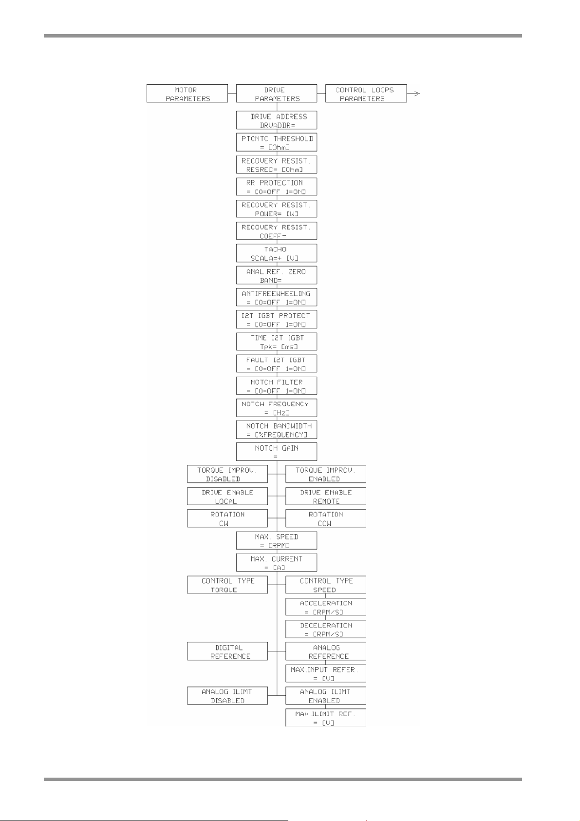
6.6
SECTION SIX – COMMANDS
6.3 DRIVE PARAMETERS MENU
Fig. 6.3 – Drive parameters menu
DS2000 USER’S MANUAL (rev.C)
Page 99

SECTION SIX – COMMANDS
6.3.1 DRIVE PARAMETERS MENU DESCRIPTION
DRIVE ADDRESS DRVADDR=
Allowed values:
from 1 to 63
PTCNTC THRESHOLD=
Allowed values:
from 100 Ω to 10000 Ω in 1 unit steps
RECOVERY RESIST. RESREC=
Allowed values:
from 3 Ω to 100 Ω in 1 unit steps
RR PROTECTION
Allowed values:
• 0 (for protection disabled)
• 1 (for protection enabled)
RECOVERY RESIST. POWER=
Allowed values:
from 10 W to 6400 W in 1 unit steps
RECOVERY RESIST. COEFF.=
Allowed values:
from 1 to 32000 in 1 unit steps
TACHO SCALE=
Allowed values:
from 5 V to 10 V in 100 mV unit steps
ANAL.REF. ZERO BAND=
Allowed values:
from 0 to 128 (128 units = 0.625 V) in 1 unit steps
Description: it indicates drive address for serial
communication
Note: set a progressive and different value per each
drive to obtain only one serial line to interrogate all
the drives existing in the machine
Description: it indicates NTC/PTC threshold value
used to protect motor from overtemperature
Note: set following value for Moog motor:
• 1200 Ω for PTC thermal feedback
• 6500 Ω for NTC thermal feedback
Description: it indicates the recovery resistor value
Note: set the value indicated on the drive label. If the
precise value is not available, set the higher one. If
the value is too high the drive will not be able to
dissipate the recovered energy
Description: protection against recovery resistor
thermal overload
Note: see section 7 for additional details on this
function setup
Description: nominal resistor power, used for
resistor thermal protection
Note: see section 7 for additional details on this
function setup
Description: special parameter, used for resistor
thermal protection
Note: see section 7 for additional details on this
function setup
Description: it indicates the max tacho signal value
obtained at max number of motor revolutions
Note: setting 10 V for the max speed value allows to
obtain a simple and direct ratio between read value
and speed
Description: set a dead band on the speed/torque
analog reference. Under this value the input is not
acquired
Note: it is useful to cut random or too big offset from
CNC. Set to 0 for normal operation
6.7
DS2000 USER’S MANUAL (rev.C)
Page 100

6.8
SECTION SIX – COMMANDS
ANTIFREEWHEELING
Allowed values:
• 0 (for disabled)
• 1 (for enabled)
I2T IGBT PROTECT
Allowed values:
• 0 (for disabled)
• 1 (for enabled)
TIME I2T IGBT=
Allowed values:
from 100 ms to 1000 ms in 10 ms unit steps
FAULT I2T IGBT
Allowed values:
• 0 (for disabled)
• 1 (for enabled)
NOTCH FILTER
Allowed values:
• 0 (for disabled)
• 1 (for enabled)
NOTCH FREQUENCY=
Allowed values:
from 50 Hz to 1500 Hz in 1 unit steps
Description: enable ANTIFREEWHEELING function
in following conditions:
• motor overtemperature
• drive overtemperature
• power lost
The drive brakes until null velocity is reached. If
recovered power is not enough the drive will shut
down without reaching null velocity. DRIVE ENABLE
signal has to be applied to activate this function
Note: ACCELERATION and DECELERATION ramps
are active for a proper operation and emergency stop
Description: enable I2T protection on IGBT if output
frequency is lower than 5kHz
Note: enabling I2T IGBT PROTECT, NOTCH FILTER
will be automatically disabled
Note: when this protection is active, the letters I2T
will appear on the main window (Moog DS2000)
menu
Description: set a time for I2T trigger
Note: default value is 500 ms for all DS2000 drives
Description: enable the fault reaction on I2T IGBT
drive condition
Note: select the “reaction” following the application
needs
• if disabled, reduce the max output current to the
rated drive current
• if enabled, fault condition (alarm and torque
disable)
Description: enable notch filter function to remove
precise critical frequency
Note: available only if I2T IGBT PROTECT is
disabled
Description: it allows to insert in the speed
adjustment loop a Notch filter which can be
programmed in frequency
Note: set directly in Hz the filter attenuation
frequency
DS2000 USER’S MANUAL (rev.C)
 Loading...