

Page 1

MRJ06301 Rev. Orig.
DigiPack
Ⅲ
Parison Wall Thickness Controller
J141-215
INSTALLATION,
MAINTENANCE
AND
USER’S MANUAL
Page 2

© MOOG 2019
This document is subject to MOOG INTELLECTUAL AND PROPRIETARY INFORMATION LEGEND . The details are on page II.
I
MRJ06301
RECORD OF CHANGES
Rev.
Page
Description
Prepared
Checked
Approved
Orig.
New Model Release(EOJ20210)
T. Kouda
15, Mar’19
T.Shimizu
15, Mar ‘19
K.Mashino
29,Mar’19
Page 3
© MOOG 2019
This document is subject to MOOG INTELLECTUAL AND PROPRIETARY INFORMATION LEGEND . The details are on page II.
II
MRJ06301
MOOG INTELLECTUAL AND PROPRIETARY INFORMATION LEGEND
This technical Document contains information that is proprietary to, and is the express property of Moog Inc., or Moog Inc. subsidiaries
except as expressly granted by contract or by operation of law and is restricted to use by only Moog employees and other persons
authorized in writing by Moog or as expressly granted by contract or by operation of law. No portion of this Data/Drawing/Document
shall be reproduced or disclosed or copied or furnished in whole or in part to others or used by others for any purpose whatsoever
except as specifically authorized in writing by Moog Inc.
NOTES TO USERS
(1) Description in this manual is subject to change without any obligation on the part of the Manufac-
turer.
(2) Notice would be appreciated if you find any question, omission or error in this manual.
(3) Disassembly, maintenance or repair, other than in accordance with the instruction herein or other
specific written instruction from MOOG will invalidate MOOG’s obligations under its warranty.
Refer to MOOG warranty for complete previsions thereof.
SAFETY INSTRUCTION
Description in this manual is essential to the safety of life and property, therefore, before operating
this equipment, you should first thoroughly read this manual, and this manual should be kept in accessible for when you have any questions.
WARNING
This symbol with the word “WARNING” is used to call attention to safety instructions
concerning a potential hazard to people. Failure to comply with these safety instructions
can result in serious damage to health and can even prove fatal in extreme cases.
CAUTION
This symbol with the word “CAUTION” is used to call attention to instructions concerning
potential damage to the equipment or to the system as a whole.
NOTE
Notes contain useful information to the operator when starting up and operating the equipment or system.
MOOG JAPAN LTD.
1-8-37 NishiShindo, Hiratsuka, Japan 254-0019
Tel:+81-463-55-7141 Fax:+81-463-54-4709
Page 4

© MOOG 2019
This document is subject to MOOG INTELLECTUAL AND PROPRIETARY INFORMATION LEGEND . The details are on page II.
III
MRJ06301
EN 61000-6-2:2005
IEC61000-4-2~6
Electromagnetic compatibility (EMC) - Part 6-2: Generic standards
- Immunity for industrial environments
EN61000-6-4:2007+A1:2011
Industrial, scientific and medical equipment - Radio-frequency disturbance characteristics - Limits and methods of measurement
About EMC Standard
1. Safety standard
Notes to certified of EC directive
J141-215 DigiPackⅢ is a device incorporated in customer's equipment (blow molding machine) and we
are conducting EMC test against EC Directive within the scope of embedded equipment, but the J141-215
DigiPackⅢ use by itself is not compatible with the EC Directive.
When customer completes the equipment with J141-215 and use it within Europe or shipment to the area
within European region as the final product, please be sure to check certified of EC Directive by customer
self.
Applicable directive and relative standard.
J141-215 is conducting the EMC test conforming to the EC directive below. It shows directives and related
standards.
EC Directive: EMC Directive 2014/30/EU
Relative Standard:
2. Measures EMC
In order to applicable EMC directive, please takes suitable measure against EMC with a customer's blow
molding machine.
And also, when include J141-215 in apparatus and it is used, please consider wire connection and grounding.
The cable used for each wire connection recommends use of a shielded cable.
A shielded cable should be connected to the terminal of J141-215, and the length of skin wire processing
should be less than 100 mm.
Page 5

© MOOG 2019
This document is subject to MOOG INTELLECTUAL AND PROPRIETARY INFORMATION LEGEND . The details are on page II.
IV
MRJ06301
TABLE OF CONTENTS
1. DigiPackⅢ Manual, Installation and Maintenance .............................................................................. 1
1-1. CHANGES FROM J141-214A ......................................................................................................... 1
1-2. INTRODUCTION .............................................................................................................................. 2
1-2-1. GENERAL DESCRIPTION.............................................................................................. 2
1-2-2. WHO CAN INSTALL THE DigiPackⅢ ............................................................................. 5
1-2-3. INSTALLATION TIME ..................................................................................................... 6
1-2-4. SOFTWARE UPDATE .................................................................................................... 6
1-2-5. BACKUP BATTERY ........................................................................................................ 7
1-2-6. SCREEN DISPLAY PROTECTION (password) ............................................................... 7
1-2-7. DATA TRANSFER FROM DigiPackⅡ ............................................................................. 7
1-3. DigiPackⅢ SPECIFICATION .......................................................................................................... 8
1-4. CHECK LIST .................................................................................................................................... 9
1-4-1. INSTALLATION CHECK LIST ......................................................................................... 9
1-5. MECHANICAL INSTALLATION ..................................................................................................... 10
1-5-1. GENERAL .....................................................................................................................10
1-5-2. TOOLING ADJUSTMENT .............................................................................................. 11
1-5-3. MOOG DIE GAP TOOLING ACTUATORS .....................................................................12
1-5-4. CYLINDER INSTALLATION ...........................................................................................12
1-5-5. CUSTOMER SUPPLIED CYLINDER REQUIREMENTS ................................................13
1-5-6. TOOLING ADJUSTMENT ..............................................................................................14
1-5-7. ACCUMULATOR POSITION MEASUREMENT .............................................................14
1-5-8. THE IMPORTANCE OF FILTRATION ............................................................................15
1-5-9. FILTER INSTALLATION .................................................................................................15
1-5-10. HYDRAULIC POWER SUPPLY ...................................................................................16
1-5-11. HYDRAULIC POWER SUPPLY START UP INSTRUCTIONS ......................................16
1-5-12. CONTAMINATION CONTROL ..................................................................................... 17
1-6. ELECTRICAL INSTALLATION ....................................................................................................... 18
1-6-1. GENERAL .....................................................................................................................18
1-6-2. REAR CONNECTOR .....................................................................................................18
1-6-3. TB-1, TB-2 WIRING .......................................................................................................19
1-6-4. COMMUNICATION AND SSI SNSOR WIRING..............................................................19
1-6-5. TB-2 I/O CIRCUITRY ................................................................................................ .....25
1-6-6. TB-3: POWER SUPPLY .................................................................................................26
1-6-7. NOISE AND GROUND ISOLATION ...............................................................................26
Page 6

© MOOG 2019
This document is subject to MOOG INTELLECTUAL AND PROPRIETARY INFORMATION LEGEND . The details are on page II.
V
MRJ06301
1-7. CALIBRATION OF TOUCH SCREEN ........................................................................................... 29
1-8. DigiPackⅢ front panel .................................................................................................................. 30
1-9. TOOLING SYSTEM SETUP .......................................................................................................... 32
1-9-1. GENERAL OF SETUP ................................................................................................ ...32
1-9-2. MACHINE SETTING ......................................................................................................32
1-9-3. SET UP PROCEDURE ..................................................................................................35
2. DigiPackⅢ Manual, User operation .................................................................................................. 43
2-1. INTRODUCTION ............................................................................................................................ 43
2-2. PARISON CONTROL..................................................................................................................... 44
2-2-1. HISTORY .......................................................................................................................44
2-2-2. PARISON PROGRAMMING BENEFITS ........................................................................44
2-2-3. CONTINUOUS EXTRUSION MACHINES .....................................................................44
2-2-4. ACCUMULATOR MACHINES ........................................................................................44
2-2-5. PARISON PROGRAMMING BENEFITS ........................................................................45
2-2-6. WITH ACCUMULATOR BLOW MOLDING MACHINES .................................................46
2-2-7. WITH CONTINUOUS BLOW MOLDING MACHINES ....................................................46
2-2-8. PARISON MOLD ALIGNMENT ......................................................................................47
2-3. MAN MACHINE INTERFACE ........................................................................................................ 48
2-3-1. OPERATOR CONTROL .................................................................................................48
2-3-2. INPUT FUNCTION .........................................................................................................48
2-3-3. FUNCTIONS ..................................................................................................................51
2-3-4. STATE MONITORING AREA .........................................................................................51
2-3-5. EDIT AREA ....................................................................................................................52
2-4. SCREENS OF EDIT AREA ............................................................................................................ 53
2-4-1. EDITING METHOD ........................................................................................................53
2-4-2. F1: Profile Mode ............................................................................................................54
2-4-3. F2: Marker Mode ...........................................................................................................59
2-4-4. F3: File Mode .................................................................................................................61
2-4-5. F4: Monitor Mode ...........................................................................................................65
2-4-6. F5: Data Display Mode ..................................................................................................66
2-4-7. SHIFT→F1: Set Up Mode ..............................................................................................67
2-4-8. SHIFT→F2: Analog monitor ...........................................................................................67
2-4-9. SHIFT→F3: File delete and Backup/Restore .................................................................68
2-4-10. SHIFT→F4: Machine Setup .........................................................................................69
2-4-11. SHIFT→F5: Communication Mode ...............................................................................70
2-5. COMMUNICATION PROTOCOL ................................................................................................... 71
2-5-1. EtherNET COMMUNICATION SPECIFICATION ............................................................71
Page 7

© MOOG 2019
This document is subject to MOOG INTELLECTUAL AND PROPRIETARY INFORMATION LEGEND . The details are on page II.
VI
MRJ06301
2-5-2. PROFILE .......................................................................................................................71
2-5-3. WAVE ............................................................................................................................73
2-5-4. MONITOR ......................................................................................................................73
2-5-5. INFORMATION DATA ....................................................................................................73
2-5-6. INTERFACE CONTROL ................................................................................................74
2-5-7. OTHER ..........................................................................................................................76
2-5-8. ERROR CODE ..............................................................................................................76
2-5-9. ADC/DAC CHANNEL ................................................................................................ .....76
2-6. PROFILE DATA LIST ..................................................................................................................... 77
2-7. SETTING UP .................................................................................................................................. 78
2-7-1. OBJECTIVE ................................ ................................................................ ...................78
2-7-2. DIE GAP TOOLING SETUP ...........................................................................................78
2-7-3. PRELIMINARY SET UP .................................................................................................79
2-7-4. INITIAL TRIALS .............................................................................................................80
Reference Drawings
CC70353 ---------- Installation
CC70355---------- Customer Wiring
Page 8

© MOOG 2019
This document is subject to MOOG INTELLECTUAL AND PROPRIETARY INFORMATION LEGEND . The details are on page II.
VII
MRJ06301
Table of Figure
Figure 1-1 DigiPackⅢ appearance - - - - - - Page 2
Figure 1-2 Basic Continuous Blow Molding Machine Control Diagram- - - Page 3
Figure 1-3 Basic Accumulator Machine Control Diagram- - - - Page 4
Figure 1-4 Start up Display - - - - - - - Page 6
Figure 1-5 Die Gap Tooling Actuator Installation - - - - Page 10
Figure 1-6 Die Gap Tooling Actuator - - - - - - Page 10
Figure 1-7 Actuator – Die Gap Tooling Mechanical Adjustment - - - Page 11
Figure 1-8 Tooling Adjustment Mechanism - - - - - Page 11
Figure 1-9 Typical Cylinder Installation - - - - - Page 12
Figure 1-10 G631-XXX Servovalve - - - - - - Page 13
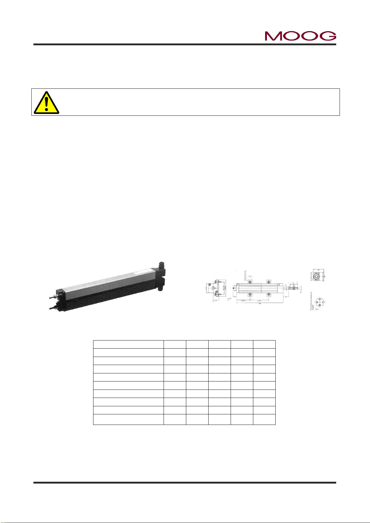
Figure 1-11 Typical Linear Potentiometer - - - - - Page 14
Figure 1-12 LWHxxx Potentiometer Installation- - - - - Page 14
Figure 1-13 High Pressure Filter - - - - - - Page 15
Figure 1-14 Hydraulic Power Supply - - - - - Page 16
Figure 1-15 Flow Pressure Filter - - - - - - Page 17
Figure 1-16 REAR CONNECTOR - - - - - - Page 18
Figure 1-17 DigiPackⅢ Installation Drawing - - - - - Page 20
Figure 1-18 ServoValve and Transducer Phasing- - - - - Page 21
Figure 1-19 TB-1 Connections - - - - - - Page 21
Figure 1-20 TB-1 Functions - - - - - - Page 22
Figure 1-21 TB-2 Connection - - - - - - Page 23
Figure 1-22 TB-2 Connection - - - - - - Page 23
Figure 1-23 TB-2 Functions - - - - - - Page 24
Figure 1-24 Input use external Power supply - - - - - Page 25
Figure 1-25 Input use internal Power supply - - - - - Page 25
Figure 1-26 Output use external Power supply - - - - Page 25
Figure 1-27 Output use internal Power supply- - - - - Page 25
Figure 1-28 Power supply Connections - - - - - Page 26
Figure 1-29 Accumulator Machine Timing chart - - - - Page 27
Figure 1-30 Continuous Machine Timing chart - - - - Page 28
Figure 1-31 Touch screen Calibration - - - - - Page 29
Figure 1-32 Touch screen calibration display - - - - - Page 29
Figure 1-33 DigiPackⅢ Flont panel - - - - - - Page 30
Figure 1-34 Machine setup display (SHIFT→F4) - - - - Page 33
Figure 1-35 Machine setting Functions - - - - - Page 33
Figure 1-36 Example of profile points change - - - - - Page 34
Figure 1-37 Setup screen - - - - - - - Page 35
Figure 1-38 Die Converge/Diverge Setup- - - - - - Page 35
Figure 1-39 Die Gap Setup - - - - - - - Page 36
Figure 1-40 DCDT Noise Filter - - - - - - Page 36
Figure 1-41 Die Gap Span Setting - - - - - - Page 37
Figure 1-42 Back - - - - - - - - Page 38
Figure 1-43 Gain select - - - - - - - Page 39
Figure 1-44 Gain setting - - - - - - - Page 39
Figure 1-45 Accumulator Setup - - - - - - Page 40
Figure 1-46 EMPTY Accumulator Set Up - - - - - Page 40
Figure 1-47 FULL Accumulator Set Up - - - - - Page 41
Figure 1-48 Extrusion Fixed- - - - - - - Page 41
Figure 1-49 Filling Fixed - - - - - - - Page 41
Figure 1-50 Accumulator setting (Back) - - - - - Page 42
Page 9

© MOOG 2019
This document is subject to MOOG INTELLECTUAL AND PROPRIETARY INFORMATION LEGEND . The details are on page II.
VIII
MRJ06301
Figure 2-1 DigiPackⅢ appearance - - - - - - Page 43
Figure 2-2 Section of an Un-programmed Parison and the Resulting Container Walls Page 45
Figure 2-3 Section of a Programmed Parison and the Resulting Container Walls - Page 45
Figure 2-4 Poor Vertical Alignment Between the Parison and the Mold - - Page 47
Figure 2-5 Good Vertical Alignment Between the Parison and the Mold. - - Page 47
Figure 2-6 DigiPackⅢ Front panel - - - - - - Page 48
Figure 2-7 Ten key on the screen (1) - - - - - Page 49
Figure 2-8 Ten key on the screen (2) - - - - - Page 49
Figure 2-9 Status indicator - - - - - - - Page 52
Figure 2-10 F1: Profile mode Screen - - - - - Page 53
Figure 2-11 Profile Mode Screen - - - - - - Page 54
Figure 2-12 0%Weight Change - - - - - - Page 56
Figure 2-13 (-)23.3% Weight Change - - - - - Page 56
Figure 2-14 0% Range H - - - - - - - Page 57
Figure 2-15 (+)25.0% Range H Change - - - - - Page 57
Figure 2-16 0% Range L - - - - - - - Page 58
Figure 2-17 (-)20.0% Range L - - - - - - Page 58
Figure 2-18 Marker Mode Screen - - - - - - Page 59
Figure 2-19 Slope Timing - - - - - - - Page 60
Figure 2-20 File Mode Selection Screen - - - - - Page 61
Figure 2-21 Select SAVE - - - - - - - Page 61
Figure 2-22 File Description Data-Page 1 - - - - - Page 62
Figure 2-23 File Description Data-Page 2 - - - - - Page 62
Figure 2-24 File Description Data-Page 3 - - - - - Page 62
Figure 2-25 Edit File name - - - - - - - Page 63
Figure 2-26 Change File Number - - - - - - Page 63
Figure 2-27 Initial Load Screen - - - - - - Page 64
Figure 2-28 File Load - - - - - - - Page 64
Figure 2-29 F4: Monito screen - - - - - - Page 65
Figure 2-30 Data Display Screen A - - - - - - Page 66
Figure 2-31 Data Display Screen B - - - - - - Page 66
Figure 2-32 Data Display Screen C - - - - - - Page 66
Figure 2-33 [SHIFT]→[F1]: Setup Screen - - - - - Page 67
Figure 2-34 [SHIFT]→[F2]: Analog Monitor Screen- - - - - Page 67
Figure 2-35 [SHIFT]→[F3]: File delete and Backup - - - - Page 68
Figure 2-36 File Delete - - - - - - - Page 69
Figure 2-37 [SHIFT]→[F4]: Machine Setup Screen - - - - Page 69
Figure 2-38 [SHIFT]→[F5]: Communication Mode Screen - - - Page 70
Page 10

© MOOG 2019
This document is subject to MOOG INTELLECTUAL AND PROPRIETARY INFORMATION LEGEND . The details are on page II.
1
MRJ06301
1. DigiPackⅢ Manual, Installation and Maintenance
1-1. CHANGES FROM J141-214A
The basic specifications of DigiPackⅢ (J141-215) are equivalent to conventional J141-214A.
There are the following major differences.
Changed from currnt VGA (480 x 640) to WXGA (1200 x 800) size
In addition, with touch screen conversion, operation by the conventional push button switch and
display by the LED are abolished, and it is changed to operation/display on the screen. (Excluding
rotary knob and power supply confirmation LED)
Considering availability, change the external storage device to USB memory. (It is not attached to
controller)
The following USB memory has been tested for operation. The operation can not be guaranteed
with USB memory other than these model numbers. We recommend that you select the same
model number as below when purchasing.
-HTU3A 16GBK
In addition, other than the above, you can refer to the list of USB memories being used without
problems by customers at the following URL:
https://www.moog.co.jp/products/controllers-software/blow-molding-controllers/digipack3.html
-tightened, and the terminal block was made detachable.
Mounting screw size is M3.5. Please use crimp terminal matching it.
Also, since the terminal block is removable, rewiring is unnecessary when replacing the controller.
Name change: DI 10 Servo OFF → Emergency. This signal is normally(under control) OFF, and
if input is ON, turns OFF the servo output. For details, refer to Figure 1-23 TB-2 Functions .
Signal addition: DI 11 temperature up completion. This signal is normally(under control) OFF, and
if input is ON, turns OFF the servo output. (Please turn ON when the resin is sufficiently warmed
up and it becomes operable.) Please refer to Figure 1-23 TB-2 Functions for details.
serial communication function
For other details, please check this manual in detail.
Page 11
© MOOG 2019
This document is subject to MOOG INTELLECTUAL AND PROPRIETARY INFORMATION LEGEND . The details are on page II.
2
MRJ06301
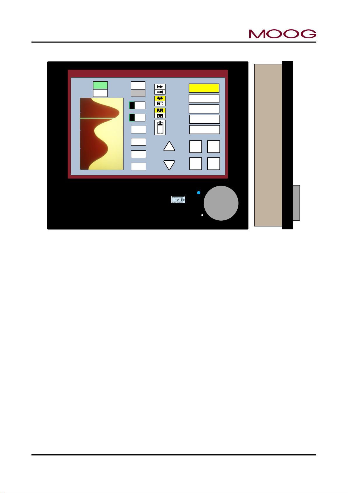
1-2. INTRODUCTION
288.00 mm
LCD Touch screen 10.1 (WVGA)
青色画面時 (RGB: 183.221.232)
DigiPackⅢ
Parison Controller
MOOG
0% 25% 50% 75% 100%
100
90
80
70
60
50
40
30
20
10
1
File Name:1234567890123456
Point No.
Die gap
Delay
Auto cycle
72
5.0
1.5
ON
%
sec
Data
Weight
Range H
Range L
* 79.0
0.0
0.0
0.0
%
%
%
%
5
6
Start
Die gap
Continuous
Accumulator
Divergent
Convergent
End of filling
Point out
End of
extrusion
F1 : Profile
F2 : Marker
F3 : File
F4 : Monitor
F5 : Data
Cursor
DEL S hift
X10 Set
2018/1/23 13:35:45
Cycle time 10.0 100% = 25.40
m
m
sec
Figure 1-1 DigiPackⅢ appearance
1-2-1. GENERAL DESCRIPTION
The J141-215 DigiPackⅢ is a user friendly, high performance 200 Point Digital Blow Molding Parison
Wall Thickness controller producing lighter, stronger containers at increased production rates.
A properly installed and intelligently used system will deliver higher operating efficiency from your blow
molding machine as a result of faster molding cycles, shorter change over times and reduced scrap.
The DigiPackⅢ adjusts the parison wall thickness by controlling the core position with the core actuator.
The core position can be finely set up to 200 points maximum.
For an accumulator type blow molding machine, set the target core position with reference to the accumulator position. For a continuous blow molding machine, set the target core position based on time.
The core position control system with the above setting consists of four main components: DigiPackⅢ
controller, servo valve, actuator for core and feedback detector for accumulator. The function of each
component is as follows.
Operator using DigiPackⅢ to set the core position (core die gap opening / closing amount) required
DigiPackⅢ also functions as a digital interface with the PLC controller of the blow molding machine
The servo valve adjusts the flow rate to the core actuator according to the flow (spool position) com-
The actuator for the core, the core is fixed to the rod, and the rod (core) moves according to the flow
to obtain a product with the desired wall thickness (usually constant wall thickness). In addition, it
outputs a flow (spool position) command to the servo valve so that the core follows the set core
position.
and provides information such as the end of the program and the point status of sequential programs.
mand from DigiPackⅢ.
rate adjusted by the servo valve. Moving the core changes the gap through which the parison passes
and controls the wall thickness of the parison.
Page 12
© MOOG 2019
This document is subject to MOOG INTELLECTUAL AND PROPRIETARY INFORMATION LEGEND . The details are on page II.
3
MRJ06301
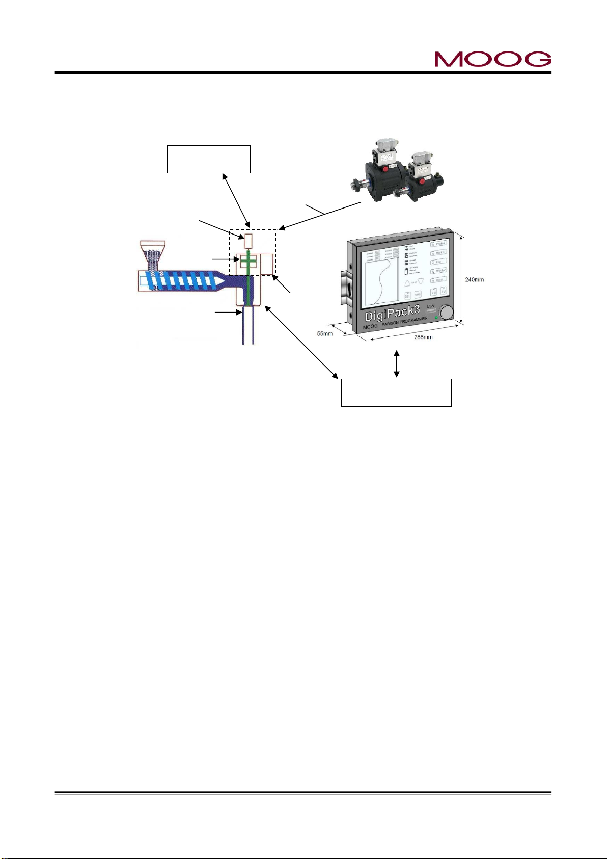
Hydraulics
Die Gap
PLC Controller
Servovalve
Actuator
DCDT
Core Position
Parison Cutoff Knife
Accumulator feedback detector is used for accumulator type blow molding machine. The DigiPackⅢ
changes the target core position while monitoring the signal from this detector.
1.2.1.1. Continuous blow molding machines
Tooling
Figure 1-2 Basic Continuous Blow Molding Machine Control Diagram
When used with continuous blow molding machines, the DigiPackⅢ controls the parison wall thickness
relative to the machine cycle time. The machine cycle starts when the start signal is input (when the parison
cutting knife disconnects the parison). The cycle time can be determined by the following.
a) Fixed cycle time set by the operator (when [Auto cycle] is OFF)
b) Automatic cycle time set by repeatedly measuring the time between start signals (when [AUTO CY-
CLE] is ON)
When using the fixed cycle time of a), it is necessary for the machine operation time to be negligible for
reasons such as multiple die interlocking, or It is a premise that it is a machine that performs machine
functions such as closing and moving molds within the cycle time
The shape of the parison wall profile is set digitally by the operator. The size of the die gap, measured by
a die gap position transducer, is compared with the operators commanded position as set on the DigiPack
Ⅲ display.
The error between the operators set position and the actual position causes the servovalve to flow oil to
the actuator to reduce the position error to a very small value. This feedback process ensures that the
actual die gap follows the commanded die gap very accurately.
With a continuous blow molding machine, DigiPackⅢ operates / processes as follows.
① The operator sets the core position (core die gap opening / closing amount) necessary to obtain the
desired wall thickness (usually constant wall thickness) product on the DigiPackⅢ controller panel.
② When the start signal switches from OFF to ON, DigiPackⅢ controls the servo valve so that the core
follows the set position according to the cycle time.
③ The servo valve adjusts the flow rate to the core actuator according to the (flow rate) command from
DigiPackⅢ.
Page 13

© MOOG 2019
This document is subject to MOOG INTELLECTUAL AND PROPRIETARY INFORMATION LEGEND . The details are on page II.
4
MRJ06301
Hydraulics
Die Gap
Actuator
PLC Controller
Servovalve
Actuator
DCDT
Position
Accumulator Push Cylinder
Accumulator
Position
④ By controlling the actuator for the core, control the thickness of the parison at the core die gap portion.
⑤ During ② to ④, DigiPackⅢ functions as a digital interface with the PLC of the blow molding machine
and provides information such as the end of the program and the point status of the program sequentially.
1.2.1.2. Accumurator type molding machines
When used with accumulator machines, the DigiPackⅢ controls the parison wall thickness relative to the
accumulator position as the plastic is being extruded.
As the total quantity or volume of plastic extruded is proportional to the accumulator position, then it follows
that the resulting parison wall thickness at any given point on the length of the container must be related
to the accumulator position. Given that the physical properties of the plastic and its temperature are constant from container to container, then each container’s weight and strength will be consistent.
Tooling
Figure 1-3 Basic Accumulator Machine Control Diagram
A potentiometer measures the accumulator position and controls the vertical axis of the program display.
The operator can also set the accumulator operating stroke, shot size, and accumulator injection comple-
tion position (cushion). In addition, DigiPackⅢ also provides interface signals to the machine's PLC for
these functions. After that, the operation of the accumulator is controlled by the PLC.
With an accumulator type blow molding machine, DigiPackⅢ operates / processes as follows.
① The operator sets the core position (core die gap opening / closing amount) necessary to obtain the
desired wall thickness (usually constant wall thickness) product on the DigiPackⅢ controller panel.
② When the start signal switches from OFF to ON, the DigiPackⅢ controls the servo valve so that the
core follows the set position according to the position of the accumulator.
③ The servo valve adjusts the flow rate to the core actuator according to the (flow rate) command from
DigiPackⅢ.
④ By controlling the actuator for the core, control the thickness of the parison at the core die gap portion.
Page 14

© MOOG 2019
This document is subject to MOOG INTELLECTUAL AND PROPRIETARY INFORMATION LEGEND . The details are on page II.
5
MRJ06301
⑤ During ② to ④, DigiPackⅢ functions as a digital interface with the PLC of the blow molding machine
and provides information such as the end of the program and the point status of the program sequentially.
Successful performance of the DigiPackⅢ depends a great deal upon how well it is installed on the
machine. By following the instructions contained idatan this manual it will be possible to easily install this
system and obtain many years of trouble free operation.
1-2-2. WHO CAN INSTALL THE DigiPackⅢ
The installation of the DigiPackⅢ control system requires the installer to be familiar with electrical wiring,
hydraulic plumbing and basic metal working. The calibration and start up of the finished system requires
some understanding of the blow molding process and use of test instruments such as a digital voltmeter.
The plumbing, wiring and bracketry should not be difficult. Most molding shop maintenance men who are
familiar with blow molding machines will have little difficulty with the help of this manual.
The system can be satisfactorily calibrated to the machine and started up without assistance or special
equipment by following the instructions in this manual.
Page 15
© MOOG 2019
This document is subject to MOOG INTELLECTUAL AND PROPRIETARY INFORMATION LEGEND . The details are on page II.
6
MRJ06301
USB memory
Save
DIGIPK3.FMW
Software version
1-2-3. INSTALLATION TIME
The time to install a DigiPackⅢ varies with the type and size of machine, mechanical constraints such
as the location of water lines and auxiliary equipment and the ability of the mechanic doing the installation.
Our experience has shown that typical maintenance men will require about 20 to 30 man hours. Smaller
machines will require less time.
Of this time, the actual machine shut down time can be held to 6 hours or less.
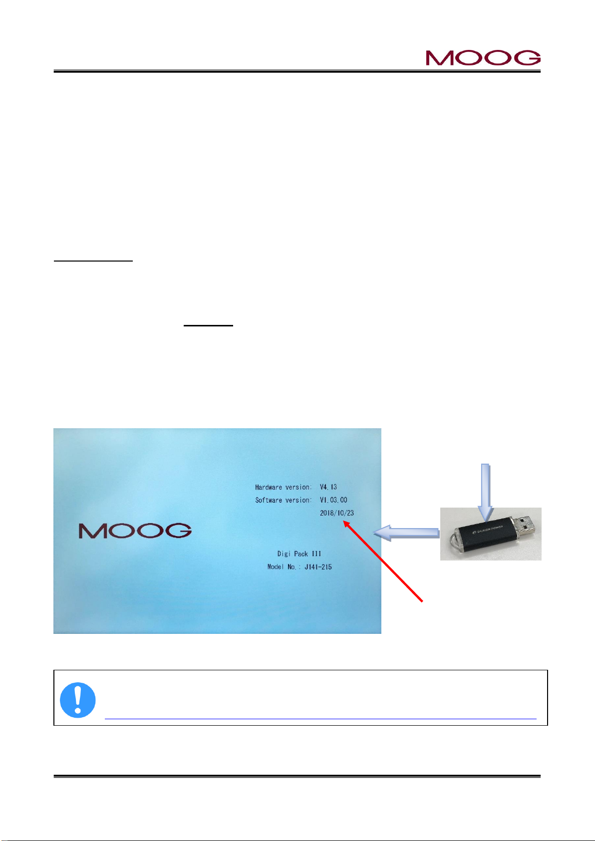
1-2-4. SOFTWARE UPDATE
The software of this controller may be updated if a bug is found or the function is improved. Please check
the software update status (latest version) from the MOOG website below. Also you can download the
update file "DIGIPK3.FMW" from the website. How to update Please refer to the following description.
Update Process
1. Prepare the USB memory and turn off the power of DigiPackⅢ.
2. Save the "DIGIPK3.FWM" file to the USB memory using the computer.
3. Insert the USB memory into the DigiPackⅢ and turn ON the DigiPackⅢ.
4. Turn the rotary knob clockwise while turning on the power.
5. When "Updating firmware ..." appears on the display, the update process is in progress.
※ It takes about 30 seconds to update. If "Failed" is displayed on the screen, or if nothing happens
and screen changed to the startup screen, the upgrade fails. Please try again from process 1. If
"Failed" is inevitably displayed and the upgrade is not successful, there is a possibility that the file
is broken. Please download "DIGIPK3.FWM" again and try update again.
6. Then check the software version in the startup display (Figure 1-4).
7. Turn off the power and remove the USB memory.
Figure 1-4 Start up Display
USB memory is not included with DigiPackⅢ. Refer to section 1-1. for recommended USB.
"DIGIPK3.FWM" can download the latest version from the MOOG website
https://www.moog.co.jp/products/controllers-software/blow-molding-controllers/digipack3.html
Page 16

© MOOG 2019
This document is subject to MOOG INTELLECTUAL AND PROPRIETARY INFORMATION LEGEND . The details are on page II.
7
MRJ06301
1-2-5. BACKUP BATTERY
Since backup of an internal clock is using the ultra capacitor, there is no necessity for exchange.
Backup time is about three weeks.
A time display may be [----.--.-- --:--] when not turning on electricity the time of the power activation after
purchase, and for a long period of time.
In such a case, please set up the right time on F2 screen. (Reference 2-4-3. )
1-2-6. SCREEN DISPLAY PROTECTION (password)
The DigiPackⅢ has two types of screen configurations that the normal operation screen (F1 to F5) and
the setting screen (SHIFT → F1 to F5) for making various settings. Each screen can be distinguished by
the color of the background. The background color of the normal operation screen is light blue " "
The background color of the setting screen is yellow " ". In this controller, the transition to the setting
screen is limited by the password. When entering the setting screen, entering a password enables you to
migrate.
* Once you enter the password, it is not necessary to enter the password until you restart the controller.
Also, if password function is unnecessary, it is possible to invalidate password from SHIFT → F4 screen.
See 1.9.2.1
Password: 6009 (Password is fixed and can not be changed)
Password input
After activating the controller, the password entry screen will be displayed when entering to the setup
screen by first pressing “SHIFT” and then pressed Fx key. Once you enter 4-digit password, you will be
able to switch to the setup screen without entering again the password. This will be retained until you
restart DigiPackⅢ.
In addition, this password can be enabled / disabled on the machine setting screen (SHIFT→ F4) . Refer
to Section 1.9.2.1 Machine Settings for details.
This level change does not indicate any notice on display. Please check the level is correctly
changes or not by press SHIFT→F1, if the level “Low” should not goes to setup display
1-2-7. DATA TRANSFER FROM DigiPackⅡ
The saving data of DigiPackⅡcan be transferred to DigiPackⅢ due to following process.
With the DIgiPackⅡsave the parameters file to SD Card and copy it to USB by using PC. Then, load
parameter file from USB to DigiPackⅢ. (Refer to 2-4-4. for save/load description)
NOTE: New parameter like PURGE/TOOLING is not include.
Page 17

© MOOG 2019
This document is subject to MOOG INTELLECTUAL AND PROPRIETARY INFORMATION LEGEND . The details are on page II.
8
MRJ06301
1-3. DigiPackⅢ SPECIFICATION
Model Number:
J141-215 DigiPackⅢ.
Function:
Max 200 points Single head blow molding Parison programmer
Application:
Accumulator Based or Continuous Extrusion Blow Molding Machines
can be selected.
Profile Points:
10 to 200,Custom points. And Straight or Spline interpolation can be
selected.
Tooling Type:
Divergent or convergent die gap tooling types can be selected.
Tooling Position Control:
Digital closed loop servo system with a 1m sec update time.
Tooling Position Monitor:
From Tooling Position Actuator’s DCDT 10 VDC.
Accumulator Position Monitor:
From Accumulator Potentiometer 0 to 10 VDC FS.
Programming Inputs:
By Rotaly knob and touch panel switches.
Display:
Color Display (LCD). 10.1 inch(WXGA) touch screen.
English/Japanese/Chinese language selected by Parameter at Setup
screen.
Memory:
100 program profile patterns can be stored in a Flash RAM. And can
be stored in USB memory.
※ Supports standard USB memory, up to 32G. (Refer to 1-1. )
※ Data format: FAT32
Point Marker:
A marker output signal can be set maximum 10 program point.
Other Functions:
Shot Size, Delay, Cushion (for accumulator machines only), die gap,
data saving, profile curve adjustment (Weight and Range H/L), adjustment of the tooling actuator stroke and the accumulator position transducer, backup for the system timer(by capacitor).
Output to Servovalve:
MFB type: ± 10, 20, 50, 100 mA or EFB type: ± 10 VDC
Servovalve Monitor:
± 100% Spool Stroke equals 4-20mA
I/O for Accumulator:
0 to 10 VDC transducer output and 10 V DC transducer excitation.
I/O for Tooling Position:
± 10 VDC DCDT output and ± 10 V DC DCDT excitation.
Common External Input:
Photo Coupler Isolated
Customer Supplied 15 to 24 Vdc @ 10 mA /Channel
24 VDC External Outputs:
Photo MOS Relay
Customer Supplied 15 to 24 Vdc @
100mA /Channel Max.
Accumulator type: End of Extrusion/Filling Relay Contacts:
250Vac @ 1 A/channel MAX.
Communication:
Data transfer with host computer by RS422 and Ethernet
Power Requirements:
24 VDC 0.5A min (MAX 3.0A depend on Servovalve Power required)
No ripple requirement : Max +-10 %
Temperature/Humidity:
0 to 45ºC within 85% relative humidity
IP rating
Front side = IP20, Rear side = IP30
Dimensions:
288 (W) x 240 (H) x 55 (D) mm (not include terminal)
Weight:
3.6 kg
Page 18

© MOOG 2019
This document is subject to MOOG INTELLECTUAL AND PROPRIETARY INFORMATION LEGEND . The details are on page II.
9
MRJ06301
1-4. CHECK LIST
*The instructions in this section are general installation procedures.
1-4-1. INSTALLATION CHECK LIST
Order parts for installation
Identify component mounting locations and procure the necessary mounting brackets
Install the DigiPackⅢ unit in the blow molding machine or optional enclosure
Mount tooling servoactuator to machine
or Mount servovalve manifold and
or Mount DCDT to tooling actuator
Mount servo actuator pressure filter
Install hydraulic power supply
Install main system filter
Make hydraulic pressure and return connections and flush the hydraulic system,
Mount accumulator position transducer, if required
Install conduit and pull cables for the tooling servoactuator, transducers, filter differential pressure switch
and interface between the DigiPackⅢ control panel and the machine PLC
Check the wiring
Calibrate transducers
Set up the control loop
Connect the actuator to the die gap tooling and adjust the die gap end points.
Page 19
© MOOG 2019
This document is subject to MOOG INTELLECTUAL AND PROPRIETARY INFORMATION LEGEND . The details are on page II.
10
MRJ06301
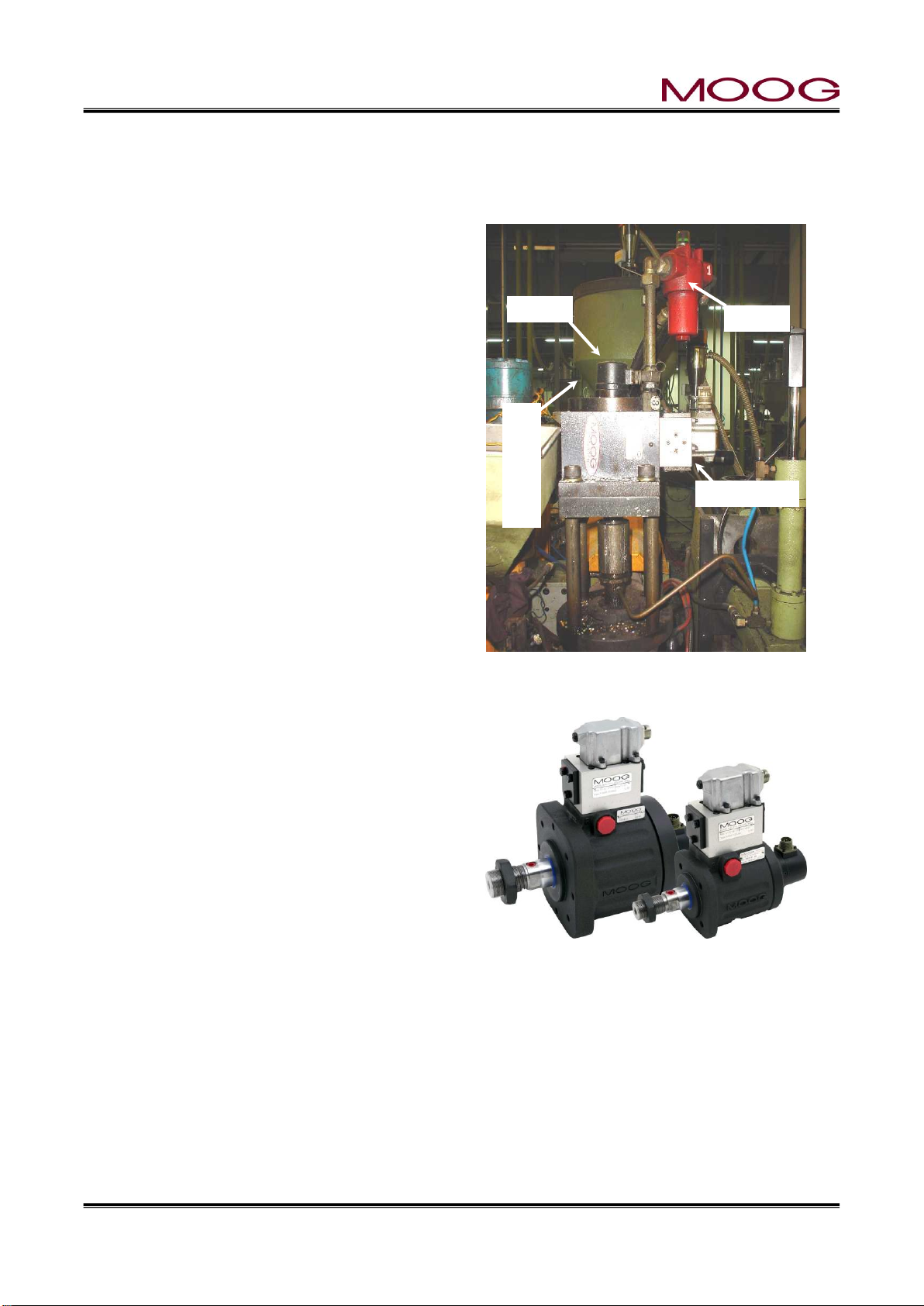
Figure 1-5 Die Gap Tooling Actuator Installa-
tion
Figure 1-6 Die Gap Tooling Actuator
Filter
Servovalve
DCDT
Tooling Actuator
1-5. MECHANICAL INSTALLATION
*The instructions in this section are general installation procedures.
1-5-1. GENERAL
Mounting provisions for the tooling servoactuator
should include a stable mounting platform for the
tooling actuator, a filter location which allows the filter
element to be readily replaced and mechanical provisions allowing simple adjustment of the mechanical
relationship between the actuator and the die gap.
Figure 1-5 shows such as a well planned installation.
A tooling servoactuator provides a long lived solution
to the problems caused by high temperatures and
force levels. Low friction seals and strong bearings
insure long term and good tooling die gap positioning
performance. A built in position transducer provides
mechanical isolation from shocks and climbing feet.
A directly manifold servovalve is tightly coupled to the
actuator. Figure 1-6 illustrates a packaged tooling actuator with provisions for pre-blow air.
Figure 1-5 shows a typical tooling actuator installation. A servovalve (upper right) is directly mounted on
a manifold, which in turn is attached to a tooling actuator. Directly below is a DCDT position transducer
measuring the actuator rod and die gap tooling motion. In addition, a high pressure filter mounted directly on the manifold provides clean oil to the servovalve. Tooling adjustment provisions are also shown.
Page 20
© MOOG 2019
This document is subject to MOOG INTELLECTUAL AND PROPRIETARY INFORMATION LEGEND . The details are on page II.
11
MRJ06301
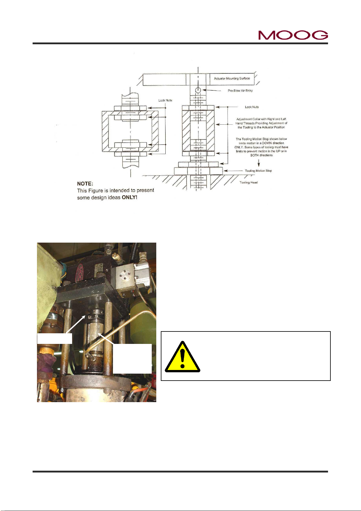
Figure 1-8 Tooling Adjustment Mechanism
Die Gap
Adjust-
ment
Lock
Figure 1-7 Actuator – Die Gap Tooling Mechanical Adjustment
1-5-2. TOOLING ADJUSTMENT
When a mold change is made, it is often necessary to
change the die gap tooling assembly. Therefore the actuator installation must provide for simple adjustment of the
die gap tooling position relative to the actuator position.
Figure 1-7 shows two possible methods of adjusting the
positional relationship between the tooling actuator and
the die gap tooling’s closed position. Tooling motion stops
may be required to limit the forces on the die gap tooling
when the die and mandrel touch. Figure 1-8 is a typical
installation.
Some actuators with an anti-rotation feature require the nut torque loads on the
anti-rotation device to be limited by absorbing the tightening torque with a
wrench on the actuator rod flats
Tooling stops are required to insure a die gap that cannot close on a continuous molding machine. An
inadvertent closure of the die gap could cause very high pressures in the extruder barrel and extrusion
head and result in their damage and/or failure.
The above comments must be considered for the proper installation of either a Moog supplied die gap
tooling actuator or a customer supplied actuator.
Page 21
© MOOG 2019
This document is subject to MOOG INTELLECTUAL AND PROPRIETARY INFORMATION LEGEND . The details are on page II.
12
MRJ06301
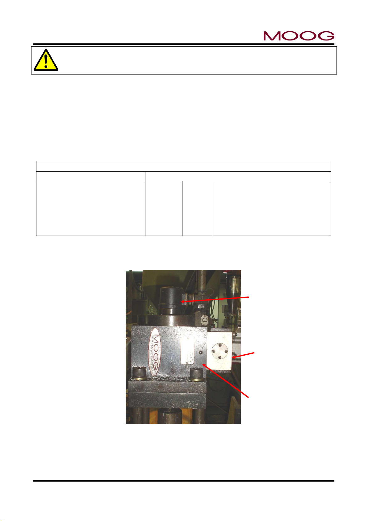
Core control Actuator (example: J085-139)
Servo Valve(G631-3004B)
DCDT Sensor
The actuator rod extends when the currents of the servo valve pins A, C are positive with respect to the currents of the pins
B, D
Pin A
Pin B
Pin C
Pin D
Pin E
+10V
-10V
+OUT
-OUT
N/A
Pin C becomes positive with respect to pin D
when retracting the actuator
Connector compatible with
MS3106-14S-5S
Servovalve
DCDT Toolong Position Transducer
Tooling Acutuator
The extruder barrel and/or screw can be severely damaged if the die gap closes when the
extruder is running. A mechanical motion stop must be installed which will not allow the die gap
to close.
1-5-3. MOOG DIE GAP TOOLING ACTUATORS
The Die Gap Tooling Actuator is designed specifically to control the die gap motion in blow molding extrusion heads. Their design specification includes: Low friction, Long life piston and rod seals. Graphite flake
cast iron rod bearings to absorb potential side loads and high temperatures. Provision for blow air through
the piston rod, and pre adjusted position feedback transducer.
The mounting provisions for a die gap tooling actuator must include: a strong mounting structure, provisions for axial and parallel alignment of the tooling actuation rod (mandrel) with the die gap actuators rod,
provisions to allow the actuator stroke center and the tooling’s effective stroke center to coincide, tooling
motion stops to protect the tooling and/or extruder. Figure 1-6 illustrates a packaged tooling actuator.
1-5-4. CYLINDER INSTALLATION
Figure 1-9 shows an installation example of Moog's die gap core control actuator.
Figure 1-9 Typical Cylinder Installation
Page 22
© MOOG 2019
This document is subject to MOOG INTELLECTUAL AND PROPRIETARY INFORMATION LEGEND . The details are on page II.
13
MRJ06301
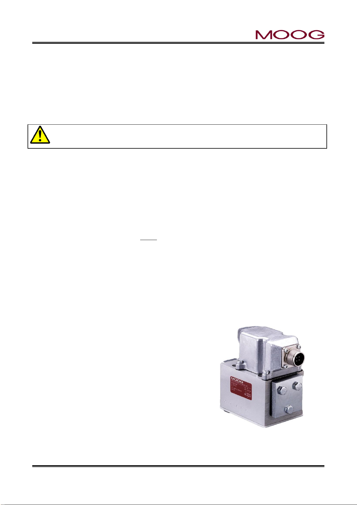
Figure 1-10 G631-XXX Servo-
1-5-5. CUSTOMER SUPPLIED CYLINDER REQUIREMENTS
The customer supplied cylinder is required to control the die gap motion in blow molding extrusion heads.
As such their purchase specification must include: Low friction, long life piston and rod seals; Robust rod
bearings capable of absorbing large potential side loads and high temperatures. A quality cylinder must
be purchased to meet these requirements.
The mounting provisions for the tooling actuator shall include: a strong mounting structure, provisions for
axial and parallel alignment of the tooling actuation rod (mandrel) with the die gap actuators rod, provisions
to allow the actuator stroke center and the tooling’s effective stroke center to coincide, tooling motion stops
to protect the tooling and/or extruder.
Some actuators with an anti-rotation feature require the nut torque loads on the anti-rotation
device to be limited by absorbing the tightening torque with a wrench on the actuator rod flats.
1.5.5.1. MANIFOLD
The manifold must be mounted using as close as possible to the cylinder. Ideal methods are to mount the
manifold directly on the cylinder, sealing the ports with “O” rings or to use tubing between the cylinder and
manifold.
The pressure and return connections should be straight thread fittings using an “O” ring as a seal. Tapered
thread fittings are not encouraged as they tend to leak and when they are torqued up to stop the leak, the
servovalve mounting surface is distorted, causing leakage at the servovalve-manifold seal. Straight thread
fittings using “O” rings do not leak or cause mounting surface distortion.
Should tapered thread fittings be used, ONLY Teflon tape can be used on the tapered threads as a sealant.
The Teflon tape must not cover the last two threads at the smaller diameter portion of the thread. Any other
material will cause eventual contamination problems.
Figure 1-7 shows two possible methods of adjusting the positional relationship between the tooling actuator and the tooling die gap closed position. Tooling motion stops may be required to limit the forces on
the die gap tooling when the die and mandrel touch. “Figure 1-9” is a typical installation.
Tooling motion stops may also be required to insure a die gap opening on a continuous molding machine.
An inadvertent closure of the die gap could cause very high pressures in the extruder barrel and extrusion
head and result in their damage and/or failure. The above comments must be considered for the proper
installation of either a Moog supplied die gap tooling actuator or a customer supplied actuator.
1.5.5.2. SERVOVALE MOUNTING
The servovalve is mounted to a manifold with four mounting
screws and using four “O” rings to seal the Pressure, Return
(Tank), and the two Cylinder hydraulic connections.
The “O” ring seal between the servovalve and manifold depends
upon the servovalve mounting manifold surface flatness to insure
that there are no oil leaks. This surface must be flat within
0.025mm and have a √32 RMS finish.
Two servovalves mounting patterns are available: a Cetop 5, NG
10 or a Ø22,2mm, Moog 76 port circle.
Page 23
© MOOG 2019
This document is subject to MOOG INTELLECTUAL AND PROPRIETARY INFORMATION LEGEND . The details are on page II.
14
MRJ06301
LWH
300
500
750
900
Electrical Data
Rated Stroke
mm
300
500
750
900
Nominal Resistance
Kohm
5 5 10
10
Independent Linearity
%
0.07
0.05
0.05
0.05
Mechanical Data
mm
Mechanical Stroke
B
312
515
769
922
Body Length
A
375
579
833
985
Mounting Feet Spacing
X
280.5
484.5
738.5
890.5
1-5-6. TOOLING ADJUSTMENT
When a mold change is made, it is often necessary to change the die gap tooling assembly. Therefore the
actuator installation must provide for simple adjustment of the die gap tooling position relative to the actuator position.
The extruder barrel and/or screw can be severely damaged if the tooling die gap closes when
the extruder is running. A mechanical motion stop must be installed which will not allow the die
gap to close.
1-5-7. ACCUMULATOR POSITION MEASUREMENT
If the DigiPackⅢ is being installed on a continuous extrusion machine please go to the next section.
Accumulator type blow molding machines require a position transducer to indicate the accumulator posi-
tion. The parison wall thickness pattern can then be programmed with direct reference to the accumulator
stroke of Shot Size.
1.5.7.1. INSTALLATION REQUIREMENTS
The position transducer is required to operate in a high temperature and vibration environment. In addition
the transducer must accommodate some mechanical miss-alignment without reduction of life and linearity.
The part of position sensor allows adjustment for interlocking the movable part of the potentiometer with
the moving of the accumulator. and also has the following functions:
1) An accumulator driven bearing guided structure for the potentiometer drive arm
2) Mounting provisions for the potentiometer on the same bearing guided structure, provisions for
adjustment to insure parallel motion of the potentiometer guide arm and potentiometer drive rod
3) And a rod end bearing between the potentiometer drive rod and the potentiometer guide arm
Figure 1-11 Typical Linear Potentiometer Figure 1-12 LWHxxx Potentiometer Installation
Installation Information
Page 24

© MOOG 2019
This document is subject to MOOG INTELLECTUAL AND PROPRIETARY INFORMATION LEGEND . The details are on page II.
15
MRJ06301
1-5-8. THE IMPORTANCE OF FILTRATION
Figure 1-13 High Pressure Fil-
ter
Adequate contamination control in any hydraulic system is the key to a
highly reliable system. Proper filter placement and selection insures
long term trouble free operation of every hydraulic system component.
There are three essentials:
1) a high pressure filter mounted directly at the tooling actuator
2) a re-circulating circuit providing continuous filtration and
heat removal
3) proper control of the tank breathing and filling operations
to prevent the ingression of contaminant
High pressure filter (β15»75, 15µ absolute) mounted directly with tubing
at the tooling actuator provides protection against particles created by
component failures.
The main contamination protection is provided by oil taken from one
corner of the tank, flowing through the low pressure re-circulating filter
back to the opposite corner of the tank. The re-circulation filter is a low
pressure filter (β3»75, 3µ absolute) with an inexpensive replacement
filter element. The re-circulation also incorporates a heat exchanger to
maintain low oil temperature and insure adequate oil life.
Protection against ingression of contaminant during oil make up and normal breathing is provided with
breather rated at 10µ.
Currently, MOOG does not sell filters. Please purchase directly from the filter manufacturer.
1-5-9. FILTER INSTALLATION
High pressure filter or equivalent, β15>75 rated, high pressure filter must be mounted as close as possible
(50mm to 300mm) to the actuator or servovalve manifold. The location of the filter must allow an easy
access to make a replacement of filter element easy and safety.
Filter Installation Information
The hydraulic connection between the filter and actuator must be tubing. Under no circumstances can
hydraulic hose be used as the hose is a contaminant generator and this contaminant will go directly into
the servovalve, eventually causing contamination problems.
The hydraulic connections used will be a straight thread “O” ring sealed boss into the servoactuator and
high pressure filter with either flared or compression fittings used to connect the tubing to the straight
thread fittings.
The use of tapered thread fittings with pipe dope will cause both contamination and leakage problems.
Teflon tape may be used, but only if applied in such a manner as to keep the edge of the Teflon tape at
least two threads away from the end of the fitting.
Page 25

© MOOG 2019
This document is subject to MOOG INTELLECTUAL AND PROPRIETARY INFORMATION LEGEND . The details are on page II.
16
MRJ06301
1-5-10. HYDRAULIC POWER SUPPLY
Figure 1-14 Hydraulic Power Supply
The Hydraulic Power Supply provides clean oil to the die gap
tooling actuator at a constant supply pressure. An accumulator
provides the peak flows that may be required. A water heat
exchanger ensures reasonable oil temperatures.
The Hydraulic Power Supply is normally used on first installations when the cleanliness condition of the blow molding machine’s hydraulic power supply is unknown or suspect.
A separate hydraulic power supply provides a reliable source
of clean oil for trouble free long term operation. A bypass filter
allows the oil to be continually cleaned and cooled.
The hydraulic power supply pressure output should be connected directly to the input port of the high pressure filter at
the die gap tooling actuator or the servovalve manifold. The
actuator or manifold return line goes to the hydraulic power
supply return port.
1-5-11. HYDRAULIC POWER SUPPLY START UP INSTRUCTIONS
1) Check for any damage to the hydraulic power supply and its parts.
2) Fill the tank through the breather filter with Shell/Tellus 68 or equivalent fluid.
3) Check the nitrogen gas pressure in the accumulator bladder. The pressure should be 35 bar or 66%
of the maximum system pressure, whichever is higher. Add nitrogen, if necessary.
4) Replace the filter elements with flushing elements. Store the original filter elements in a clean, very
clean plastic bag.
5) Connect the pressure and return lines to and from the tooling actuator assembly
6) Check the motor name plate for the correct line voltages and connect the motor to power. Start the
motor and check that it rotates in the proper direction.
7) Connect cooling water to the heat exchanger. The required water flow rate is 30 1/min at 2-3 bar.
8) Run the hydraulic power supply for at least 6 hours. Vary the flow rate and pressure to thoroughly
flush all chips and dirt into the filters. Monitor for leaks and repair.
9) Replace the flushing filter elements with the elements removed in step 4.
Page 26

© MOOG 2019
This document is subject to MOOG INTELLECTUAL AND PROPRIETARY INFORMATION LEGEND . The details are on page II.
17
MRJ06301
1-5-12. CONTAMINATION CONTROL
Figure 1-15 Flow Pressure Filter
Long term trouble free operation with a minimum of unplanned
down time and adequate oil contamination control are linked very
closely. It is very important to maintain adequate oil cleanliness.
The addition of a system contamination control filter will control
oil contamination levels at minimum expense.
The filter should be located such that the flow through the filter is
relatively constant and at a low pressure. The junction of the return lines from the tooling actuator and the system relief valve is
a suitable location.
Currently, MOOG does not sell filters. Please purchase
directly from the filter manufacturer.
Page 27
© MOOG 2019
This document is subject to MOOG INTELLECTUAL AND PROPRIETARY INFORMATION LEGEND . The details are on page II.
18
MRJ06301
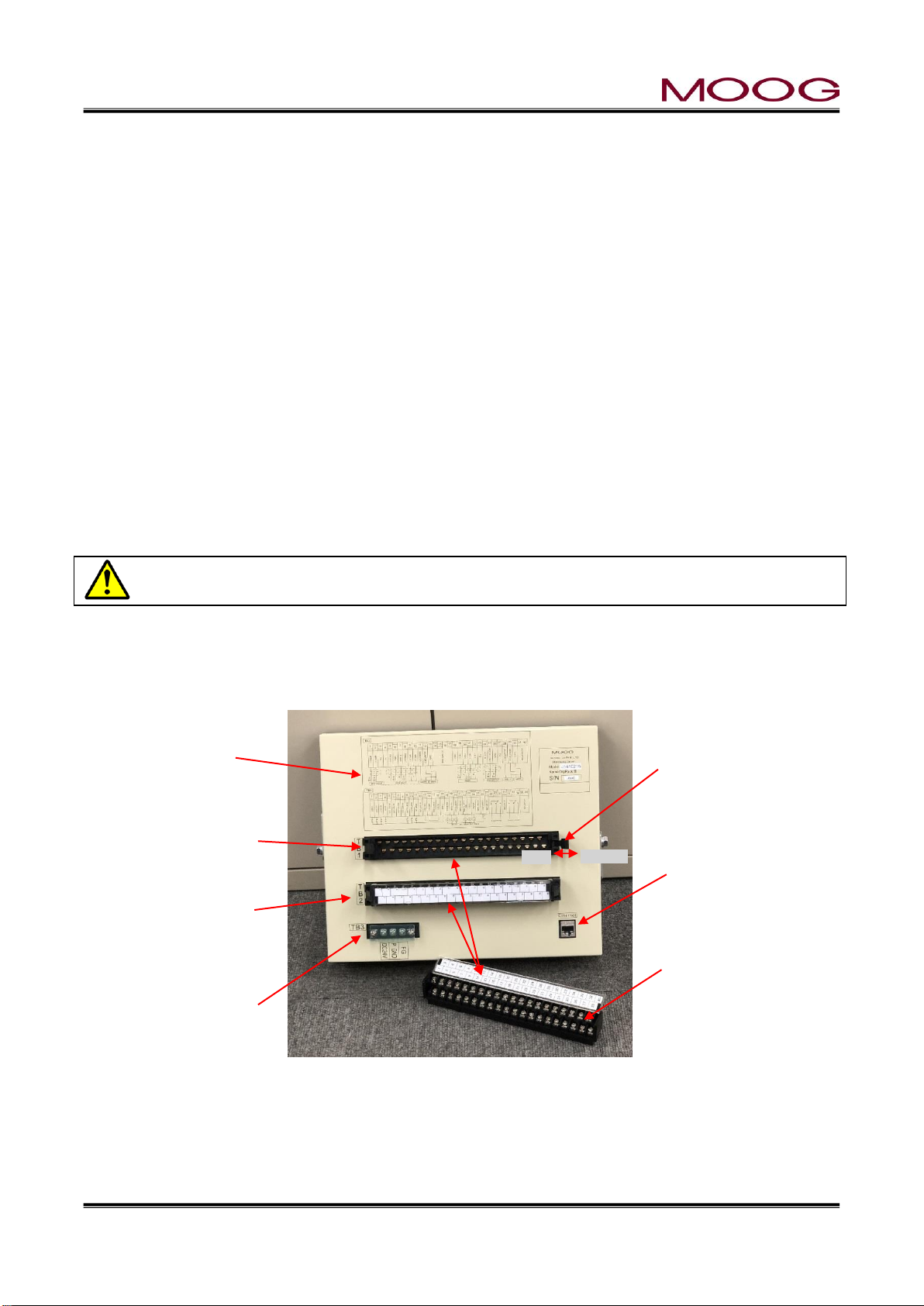
Lock lever
Please lock securely
when fixing the connector.
TB-3:Power connector
(Screw diameter 3.0 mm,
tightening torque 0.6 Nm)
Reference wiring
diagram
Ethernet Plug
TB-1:Base connector
Connector removal status
(Screw diameter 3.5 mm,
tightening torque 1.0 Nm)
Release
Lock
TB-2 : Connector
installation state
Desorption
1-6. ELECTRICAL INSTALLATION
1-6-1. GENERAL
Electrical installation includes several phases of work:
A) mounting the DigiPackⅢ in a suitable location
B) determining the correct phasing so the servovalve, tooling position transducer and, possibly,
accumulator position transducer may be connected to the DigiPackⅢ
C) determining the blow molding machine interface interaction with the DigiPackⅡand then
wiring the machine-DigiPackⅢ interface
D) connect the DigiPackⅢ to electrical power supply from the stable 24VDC
DigiPackⅢ MOUNTING
The DigiPackⅢ must be mounted in a location free of vibration, with protection from the environment and
most important, located in a position allowing the operator and setup man easy visual and physical access.
It is recommended that the mounting be on a swing out panel allowing easy access to the front and back
sides of the DigiPack3.
Mounting information is shown in “Figure 1-17”. Brackets providing simple panel mounting are included.
All wiring from the DigiPackⅢ must be shielded. The shield is to be grounded to the DigiPackⅢ
ground at the DigiPackⅢ only Any other ground paths may cause damage.
1-6-2. REAR CONNECTOR
The rear connector of DigiPackⅢ can be detached. When installing the connector, secure with the lock
lever. See Figure 1-16.
Figure 1-16 REAR CONNECTOR
Page 28

© MOOG 2019
This document is subject to MOOG INTELLECTUAL AND PROPRIETARY INFORMATION LEGEND . The details are on page II.
19
MRJ06301
Pin No.
Signal
Connection
1
TD+
2 TD-
3 RD+
4
5
6 RD-
7
8
1-6-3. TB-1, TB-2 WIRING
The wire size for TB-1 and TB-2 are able to use AWG26 - 16(Recommended AWG 19-18, 0.75 mm2),
and required using O type or Y type crimp terminal. (Screw diameter 3.5 mm, tightening torque 1.0 Nm).
TB-1 provides the interface between the DigiPackⅢ and the servovavle, die gap sensor, accumulator
position sensor. TB-1 also provides outputs to optional customer monitors MFB Valve current, EFB spool
monitor, DCDT input voltage, Accumulator voltage, Position command, these signals can be select at
setting display (See 2-4-8. ). A schematic of TB- 1 is shown as “Figure 1-19” and TB-1 functions are
outlined in the table, “Figure 1-20”.
Phasing definitions for the servovalve, die gap position and accumulator position (if used) transducers are
given in “Figure 1-18”.
Some connections to TB-1 are shown in parenthesis, (), in “Figure 1-19”. The parenthesis, (), indicate
alternate connection possibilities result from particular directions of motion or phasing determined during
the design of the mechanical installation. Phasing requires that a defined direction of motion of the tooling
actuator will result from TB-1-1 being negative with respect to TB-1-2; that the output voltage of the die
gap position transducer be positive or negative when the die gap is moving in a specific direction; and that
the accumulator position transducer output voltage direction be defined when the accumulator is ejecting
molten plastic into the die head. Terminal TB-2 is using the external power supply to isolate logic inputs,
“Figure 1-21, Figure 1-22”, TB-2 functions are outlined in “Figure 1-23”.
1-6-4. COMMUNICATION AND SSI SNSOR WIRING
The DigiPackⅢ can be communicate with host computer by Ethernet. The connector is using RJ45
socket type for Ethernet (connector name label “Ethernet”). Please refer to Figure 1-17 for connector
location. And connector pin assign see below list.
Ethernet connector RJ45 socket “Ethernet”
Page 29

© MOOG 2019
This document is subject to MOOG INTELLECTUAL AND PROPRIETARY INFORMATION LEGEND . The details are on page II.
20
MRJ06301
Figure 1-17 DigiPackⅢ Installation Drawing
Page 30

© MOOG 2019
This document is subject to MOOG INTELLECTUAL AND PROPRIETARY INFORMATION LEGEND . The details are on page II.
21
MRJ06301
57986104
Figure 1-18 ServoValve and Transducer Phasing Figure 1-19 TB-1 Connections
Page 31

© MOOG 2019
This document is subject to MOOG INTELLECTUAL AND PROPRIETARY INFORMATION LEGEND . The details are on page II.
22
MRJ06301
Name IN/OUT Function Comments
1 -MFB Signal PinA or D, B to C, MEB Servo valve (MFB) Mechanical Feedback
2 +MFB Signal PinA or D, B to C, MEB Servo valve Connection A to D or D to A allow phase reversal
3 F GND(Cable Shield) Cable Shield ground, MFB Servo valve Do not ground the shield at the servovalve
4 F GND(Cable Shield) Cable Shield ground, EFB Servo valve Do not ground the shield at the servovalve
5 24V DC OUT Pin A, EFB Servo valve (EFB )Electrical Feedback Valve Power. Max 1.5A available
6 GND OUT Pin E or D, EFB Servo valve The polarity is reversed depending on the connection of pin D / E
Connection example
7 P GND Pin B, EFB Servo valve
8 EFB Signal OUT Pin D or E, EFB Servo valve EFB Signal : ±10V OUT
MFB Servo valve
9 Valve Spool(-) Pin C, EFB Servo valve 1 A
10 Valve Spool(+) Pin F, EFB Servo valve 2 D
3 Shield
11 Monitor 1 Monitor Out 1 ±10 V DC OUT. Signal selectable
12 Monitor 2 Monitor Out 2 ±10 V DC OUT. Signal selectable
EFB Servo valve
13 GND Monitor Ground Ground for Monitor 1 and 2 5 A
14 NOT USE 7 B
15 NOT USE 9 C
16 NOT USE 8 D
17 NOT USE 6 E
10 F
18 GND 4 Shield
19 DCDT IN (+) IN Pin C or D : DCDT Feedback signal (+) (DCDT) Parison core position feed back sensor
20 +10V DC OUT Pin A : DCDT Power voltage (+10V) The level of the feedback signal changes depending on the type of DCDT (maximum: ± 10 V)
Core Position (DCDT)
21 DCDT IN (-) IN Pin D or C : DCDT Feedback signal (-) The polarity is reversed depending on the connection of pin C / D 20 A
22 -10V DC OUT Pin B : DCDT Power voltage (-10V) 22 B
23 F GND(Cable Shield) Cable Shield ground, DCDT Do not ground the shield at the Actuator or DCDT 19 C
21 D
24 ACC IN IN Pin 2, Potentiometer (ACC Pot) Accumulator position feed back sensor 23 Shield
25 ACC VLT OUT Pin 1 or 3, Potentiometer Available accumulator type: Internal resistance 1 kΩ or more
26 GND Pin 3 or 1, Potentiometer
ACC Position (POT)
27 F GND(Cable Shield) Cable Shield ground, Accumulator Do not ground the shield at the Accumulator 25 1
24 2
28 Monitor 3 Monitor Out 3 ±10 V DC OUT. Signal selectable 26 3
29 Monitor 4 Monitor Out 4 ±10 V DC OUT. Signal selectable 27 Shield
30 GND Monitor Ground Ground for Monitor 3 and 4
31~40 NOT USE
OUT
OUT
TB-1: Analog I/O Terminals (Moog Production and Transducers)
Term No.
OUT
±10, 20, 50, 100 mA
IN
Spool Signal : 4-20mA
Figure 1-20 TB-1 Functions
Page 32

© MOOG 2019
This document is subject to MOOG INTELLECTUAL AND PROPRIETARY INFORMATION LEGEND . The details are on page II.
23
MRJ06301
Figure 1-21 TB-2 Connection
with Internal Logic Supply
Figure 1-22 TB-2 Connection
with External Logic Supply
Page 33

© MOOG 2019
This document is subject to MOOG INTELLECTUAL AND PROPRIETARY INFORMATION LEGEND . The details are on page II.
24
MRJ06301
※ Minimum acceptance time of digital input is 50msec or more
Name IN/OUT Function Comments (Refer Fig1-20, 1-21)
1 IN1 START IN Command for Cycle Start Enable machine cycle start.
2 IN2 DIE GAP IN Command to keep the tooling die gap It is valid at any time by continuous mode. Cycle is stops
at the set Die Gap value until IN1 START Accepted only at injection completion state (END EXT) at ACC mode
3 IN3 REBOOT IN Reboot switch for controller. Not accepted during machine cycle
4 IN4 STOP IN Command for Stop operation Cycle stop, hold at current position
5~8 NOT USE
9 IN9 START SLOPE IN
A command to move the core from the current position to the position of the first point
Maintain position until start after moving completes.
The movement speed is set on the screen. Not accepted during machine cycle
10 IN10 EMERGENCY IN Servo OFF command. (E-Stop)
When it is High, the servo valve signal is stopped.
Because it is an emergency stop, accept at any time
ON = Emergency state
11 IN11 TEMP. OK IN Temperature rise completion confirmation.
When this signal is High, the servo valve signal is stopped.
ON = Temp not rised
12 NOT USE
13 INPUT COM.
14 INPUT COM.
15 NOT USE
16 24V DC
17 P GND
18 END FLG. OUT
ON at End of Filling.
Maintain until it falls below the position of End Filling
With this signal, the filling of the accumulation is stopped
19 END EXT. OUT ON at End of Extrusion. With this signal, the injection of the accumulation is stopped
In Continuous mode: ON until the next start.
※ In the case of Accum mode 1% hysteresis (injection & filling)
In Accumulator mode: ON while the accumulation position is smaller than
the injection completion position
20 MARKER OUT OUT Marker output signal. Output at the specified marker point Pulse width 200 msec
21 NOT USE
22 END ST SLOPE OUT At start slope input, ON at movement completion, maintain until IN1 start input
23 READY OUT Turn on when the start condition is set When this signal is ON, controller can receive the start signal.
※ This is not an interlock. Just inform to the host controller
24 ALARM OUT When both IN10 and IN11 are High and output (OFF=alarm state)
25 NOT USE
26 OUTPUT COM. Common for Digital Output Both Sink/Source support. For details see manual page 25
27 NOT USE
28 EOF Relay COM END OF FILLING Relay Common
29 EOF Relay B END Relay Contact B (NC)
30 EOF Relay A END Relay Contact A (NO)
31 NOT USED
32 EOE Relay COM END OF EXTRUSION Relay Common
33 EOE Relay B END Relay Contact B (NC)
34 EOE Relay A END Relay Contact A (NO)
35~40 NOT USE
Common for Digital Input (Isolation)
Pin 13-14 is internally connected.
Both Sink/Source support. For details see manual page 25
Digital signal power supply for both IN/OUT
Maximum current out : 3.0A
Relay
Relay output、AC250V、Maximum 1A
Relay
Relay output、AC250V、Maximum 1A
TB-2: General I/O Terminals
Term No.
Figure 1-23 TB-2 Functions
Page 34

© MOOG 2019
This document is subject to MOOG INTELLECTUAL AND PROPRIETARY INFORMATION LEGEND . The details are on page II.
25
MRJ06301
1-6-5. TB-2 I/O CIRCUITRY
Input _________________
Figure 1-24 Input use external Power supply Figure 1-25 Input use internal Power supply
All DigiPackⅢ I/O can be uses both POSITIVE/NEGATVIE LOGIC
DigiPackⅢ can be used external and internal power supply. And provide isolated inputs.
The external power supply has an output 24VDC.
The contacts used must have very low contact resistance over a long life time.
Extreme care is required when wiring to insure that ground loops do not exist. Ground loops can cause
damage to the DigiPackⅢ and other electronic equipment. Ground loops can also cause erratic operation
of the entire blow molding machine.
Output ___________________
Figure 1-26 Output use external Power supply Figure 1-27 Output use internal Power supply
DigiPackⅢ’s output circuits use Photo MOS Relay to provide isolation from the external circuitry.
The maximum voltage and current output to each load terminal (TB-2, 18, 19, 20, 22, 23 and 24) is 24VDC
and 100 mA MAX/each.
Page 35

© MOOG 2019
This document is subject to MOOG INTELLECTUAL AND PROPRIETARY INFORMATION LEGEND . The details are on page II.
26
MRJ06301
Term No.
Name
Specification
DC24V
Power Supply 24V
24V DC Input 0.5A min – 3.0A max
* Required install Fast blow Fuse.
* No ripple required, Max +-10 %
P GND
Power Supply 0V
0V (for DC 24V)
F GND
Earth
1-6-6. TB-3: POWER SUPPLY
The wire size for TB-3 is able to use AWG17 – 16, 1.75 mm2, and required using O type or Y type crimp
terminal. (Screw diameter 3.0 mm, tightening torque 0.6 Nm).
There is protection that does not break down with reverse wiring, but please be careful because
input of high voltage will damage the circuit.
Figure 1-28 Power supply Connections
1-6-7. NOISE AND GROUND ISOLATION
In any location there is always the potential for electrical noise interference and multiple ground paths.
Electrical noise can cause erratic system operation and is very difficult to find and isolate, ground
loops also cause unexpected operation as well as burn out components. In addition, mains voltage
stability can sometimes be questionable.
An isolation transformer between the mains and DigiPackⅢ can provide some relief from noise,
ground loops and wandering mains.
Page 36

© MOOG 2019
This document is subject to MOOG INTELLECTUAL AND PROPRIETARY INFORMATION LEGEND . The details are on page II.
27
MRJ06301
Figure 1-29 Accumulator Machine Timing chart
Page 37

© MOOG 2019
This document is subject to MOOG INTELLECTUAL AND PROPRIETARY INFORMATION LEGEND . The details are on page II.
28
MRJ06301
Figure 1-30 Continuous Machine Timing chart
Page 38

© MOOG 2019
This document is subject to MOOG INTELLECTUAL AND PROPRIETARY INFORMATION LEGEND . The details are on page II.
29
MRJ06301
1-7. CALIBRATION OF TOUCH SCREEN
Calibration of the touch screen has already been completed at the time of product shipment, so basically
no user setting is necessary. Here is explain that the readjustment method when there is an error in the
calibration of the touch screen by some reasons. (If there is an error in the calibration of the touch screen,
the touch area corresponding to the display button will shift, so it will not react even if you touch the display
button.)
If the readjustment becomes frequently necessary, it seems that some trouble has occurred on
the touch screen. In that case we recommend that you submit it for repair.
Step 1: While DigiPackⅢ powered on, digital signal is continuously input for 3 seconds or longer to TB-
2-8 (this channel displayed as Do not use).
Step 2: DigiPackⅢ will be automatically restarted and the calibration screen as shown in Figure 1-31 will
be displayed. Touch the "Calibration" button. (At this time, since the calibration information is reset,
"Calibration" button can be pressed)
Step 3: Since Figure 1-32 is displayed, touch all the "+" signs surrounded by the red frame square in the
corner. If you press the wrong place to push, the calibration will fail and the screen will stop responding. In that case, please turn on the power again, return to step 1 and try again.
Step 4: If the calibration is successful, display will return to Figure 1-31, Restart the controller and finish.
Figure 1-31 Touch screen Calibration
Figure 1-32 Touch screen calibration display
Page 39

© MOOG 2019
This document is subject to MOOG INTELLECTUAL AND PROPRIETARY INFORMATION LEGEND . The details are on page II.
30
MRJ06301
1-8. DigiPackⅢ front panel
288.00 mm
LCD Touch screen 10.1 (WVGA)
青色画面時 (RGB: 183.221.232)
DigiPackⅢ
Parison Controller
MOOG
0% 25% 50% 75% 100%
100
90
80
70
60
50
40
30
20
10
1
File Name:1234567890123456
Point No.
Die gap
Delay
Auto cycle
72
5.0
1.5
ON
%
sec
Data
Weight
Range H
Range L
* 79.0
0.0
0.0
0.0
%
%
%
%
5
6
Start
Die gap
Continuous
Accumulator
Divergent
Convergent
End of filling
Point out
End of
extrusion
F1 : Profile
F2 : Marker
F3 : File
F4 : Monitor
F5 : Data
Cursor
DEL Shift
X10 Set
2018/1/23 13:35:45
Cycle time 10.0 100% = 25.40
m
m
sec
Rotaly Knob
Used to enter the value of various functions. Rotation in a clockwise
X10
Increases the sensitivity of the Rotaly Knob by a factor of 10
SET
Push to set value
DEL
Invalidates the set profile data and changes it to interpolation data.
Rotaly Knob
USB slot
Beep sound speaker
Edit area
Switched by
F1 to F5
Other
Switch
Power LED
State monitoring area
Figure 1-33 DigiPackⅢ Flont panel
OPERATIONS CONTROLS
The operator will setup and monitor the parison wall thickness program using the display switches and
Rotaly knob on the DigiPackⅢ’s front panel, shown in “Figure 1-33”
Beep sound
A beep sounds when parameters and keys in the screen are selected. Also, if an error occurs at startup
and normal startup can not be performed, A beep sounds ON/OFF is repeated continuously.
Power LED
It lights up with 24 VDC being supplied. Also, if an error occurs at startup and normal startup can not be
performed, ON/OFF is repeated continuously.
All of the functions normally required to program the parison and machine are available on the front panel.
|INPUT FUNCTION SELECTION AND VALUE
Page 40

© MOOG 2019
This document is subject to MOOG INTELLECTUAL AND PROPRIETARY INFORMATION LEGEND . The details are on page II.
31
MRJ06301
SHIFT
While pressing "SHIFT" is active, the screen called by the F1 to F5 switches becomes
the setting screen. If you push this switch again or select one of F1 to F5 setting screen,
"SHIFT" becomes inactive. *Refer to 1-2-6. for protection of setting screen transition
Cursor △▽
Used to scroll the items on the LCD in the direction indicated by the triangular shape
Start
Lights when the cycle Start signal is received.
Die Gap
Lights when the Die Gap signal is received and “DIE GAP” on the LCD is lit
Continuous
Lit when the “Continuous Extrusion” machine type is selected
Accumulator*
Lit when “Accumulator” machine type is selected
Divergent
Lit when “Divergent” die gap tooling is selected
Convergent
Lit when “Convergent” die gap tooling is selected
End of Filling
Lights at the end of the accumulator filling stroke
Point Out
Lights when each Marker point is reached
End of Extrusion*
Lights at the end of the accumulator extrusion stroke (Cushion)
F1 Profile
Controls the parison wall profile and other related functions. (When start up the controller, move to this screen first)
F2 Marker
Set the program point markers. And set the slope(Speed) that do to Die gap and start
position. Internal clock time setting. PURGE/TOOLING core opening setting
F3 File
Controls the container wall thickness storage functions
F4 Monitor
Indicate the digital I/O, current value of servovalve input current and core position. Manual operation is also done on this screen.
F5 Data
Displays the profile point and related function data
SHIFT→F1
SET UP Mode - Provides die gap tooling and other machine related set up functions
SHIFT→F2
Signal assign to Monitor Analog output
SHIFT→F3
Delete and Backup/Restore the storage data.(Backup/Restore for data in USB
memory)
SHIFT→F4
Machine setting setup
SHIFT→F5
Communication parameter setting of Ethernet.
Highlights are used to indicate the action function or its value to the operator. You can change
the value of the highlighted parameter by turning the rotary knob or inputting from the numeric
keypad. *The numeric keypad is displayed on the screen after touching the same parameter
again or turning the rotary knob after specifying the parameter. For details, refer to section 23-2.
STATE MONITORING AREA
In the status monitoring area shown in Figure 1-33, it is used to indicate the status of the following functions.
SWITCH OF F1 TO F5
It is used to select the function screen displayed in the editing area shown in Figure 1-33. The contents of
the function are as follows.
Page 41

© MOOG 2019
This document is subject to MOOG INTELLECTUAL AND PROPRIETARY INFORMATION LEGEND . The details are on page II.
32
MRJ06301
1-9. TOOLING SYSTEM SETUP
1-9-1. GENERAL OF SETUP
The Mechanical and Electrical installation must be finished before the Dig Gap Tooling position
control system can be set up. In addition the, hydraulic system must have been flushed for at
least 24 hours.
The Die Gap Tooling position control system setup involves several steps:
1) The Machine setup in the DigiPackⅢ display (SHIFT→F4) must be set to match various
options determined by the blow molding machine and tooling head type.
2) The correct tooling type selection, Convergent or Divergent, must be determined. This
will be determined by which portion of the tooling moves, the die or mandrel, as well as
its internal shape.
3) The DigiPackⅢ must know if the blow molding machine is a Accumulator or a Continuous molding machine.
4) The working Die Gap end positions, closed and maximum open, must be set.
5) The responsiveness of the Die Gap Tooling position control system is measured and
optimized.
When finished with the Die Gap Tooling system setup, the blow molding machine will be ready to be
programmed for production containers.
The hydraulic pressure must be lowered during the setup procedure or the die gap tooling
may be damaged.
1-9-2. MACHINE SETTING
After confirming the mechanical and electrical connection completely, turn on the DigiPackⅢ. However,
please do not apply hydraulic pressure yet here.
The LCD of DigiPackⅢ gets brighter and [F1 Profile] is displayed via the startup screen. Next, press the
[SHIFT] → [F4] key in that order to reflect the machine settings such as language, servo valve type, con-
tinuous type machine or accumulator type machine.
1.9.2.1. MACHINE SETTINGS (SHIFT→F4)
At the DigiPackⅢ display “SHIFT -> F4” (“Figure 1-34”) is Setting for Machine setting. Set these parameters according to Machine type, these parameters should setting before start setting any parameter of
tooling and accumulator. (Accumulator setting only accumulator machine)
The settings required now are:
1) Machine type - Either Continuous or Accumulator
2) Servovalve type - Either mechanical feedback, MFB, or electrical feedback, EFB
3) Valve current - If selected MFB type, this parameter can be selected current level
10, 20, 50 or 100 mA
Depending on the setting of MFB and EFB, the output terminal changes. (The output terminals of
MFB/EFB are located in TB-1.) The Servovalve type that not set is fixed to "0" mA or "0" V, if no
output signal and the actuator does not operate, Please review the machine setting.
Page 42

© MOOG 2019
This document is subject to MOOG INTELLECTUAL AND PROPRIETARY INFORMATION LEGEND . The details are on page II.
33
MRJ06301
Function name
Setting
Profile points
10/20/30/50/100/200
Custom
Any value between 10-200
Profile interpolation
Straight
Spline
Language
English
Chinese
Japanese
Back light (min)
5
10
30
-- (no screen saver)
LCD
Contrast. Knob CCW : dark, Knob CW : bright
Memory
ON
OFF
Password
ON
OFF
Above 7 parameters are updated always
Machine Type
Continuous
Accumulator
Servovalve type
MFB
EFB
Valve current (mA)
10
20
50
100
-- (*Note)
Open command
Disable
Enable
The above 4 parameters are updated by pressing the switch in the order of [Reboot]->[SET], by being
restarted
*Note) When [Servovalve type] is set to [EFB], it automatically becomes ± 10 V output.
Figure 1-34 Machine setup display (SHIFT→F4)
“Figure 1-35” defines all of the settings.
Figure 1-35 Machine setting Functions
It is necessary to execute Reboot whenever you change the setting. When moving to another
screen without Reboot, the parameter returns to its original value. When you press [Reboot] →
[SET], DigiPackⅢ will be restarted. Do not apply hydraulic pressure when executing [Reboot].
Page 43

© MOOG 2019
This document is subject to MOOG INTELLECTUAL AND PROPRIETARY INFORMATION LEGEND . The details are on page II.
34
MRJ06301
1.9.2.2. MACHINE SETTING (SHIFT → F4) FUNCTION
Profile points
It is possible to specify the number of set points in the profile display (F1) from
[10/25/30/50/(*)100/200 / Custom]. When [Custom] is specified, it is possible
to specify the number of profile points freely between 10 and 200 points.
Profile interpolation
Sets a interpolation (*)Straight or Spline on the profile display (F1)
Language
Language – ((*)English/ Chinese / Japanese) Sets the language used on the
LCD Display
Back light (min)
Sets the timer of screen saver. 5, 10, (*)30 min or non screen saver.
LCD
Adjust the screen brightness. Knob CCW : dark, Knob CW : bright
Memory
Select actual feedback line indicated on profile display. (*)ON : Show, OFF :
Not Show
Password
Sets to enable or disable of password protection at the migration of setting
screen.
(*) ON: Enabled, OFF: Disable * When disabled, there is no protection for
setting screen transition.
Machine Type
Machine type – Accumulator or (*)Continuous
Servovalve type
Servovalve type – EFB or (*)MFB
Valve current
Valve current of MFB type – 10, 20, 50 or (*)100 mA
Open command
Cursor move admission to Open command on Monitor display (F4) Enable or
(*)Disable
Marked as (*) is initial setting with new DigiPackⅢ shipped.
When “Profile Points” is changed, if the value is not specified in the original profile at the final
point of the new profile (for example, 25th points of when specified 25 points) If it was interpolated value, the new 25th point in the profile is specified as the height "0". Also, when the
number of profile points is increased (Example 100 to 200), the profile of the newly added part
is specified as the height "0". See Figure 1-36
Figure 1-36 Example of profile points change
Page 44

© MOOG 2019
This document is subject to MOOG INTELLECTUAL AND PROPRIETARY INFORMATION LEGEND . The details are on page II.
35
MRJ06301
1-9-3. SET UP PROCEDURE
To go to Set Up mode press “SHIFT” then press “F1”. The
Set Up mode screen appears as shown in “Figure 1-37”.
Three words [DCDT], [Accumulator], and [Gain] are displayed on the left side of the screen. By selecting them, you
can set DCDT, accumulator and gain value respectively.
The highlighted word (in this case [DCDT]) indicates the
setup screen that will transition when you press [SET]. However, [Accumulator] is displayed only when it is set to accumulator type mode at [Machine] setting ([SHIFT]→[F4]).
Note that the [DCDT], [Accumulator], and [Gain] screens
have a button as "Back" under the setup parameters of the
screen. If [Back] is highlighted and you press [SET] or directly touch [Back] on the screen, the display returns to the
setup screen (Figure 1-37).
1.9.3.1. DCDT SETUP
To go to the [DCDT setupup] screen, press [SET] when
[DCDT] is highlighted in Figure 1-37 or directly touch
[DCDT] on the screen.
The screen shown in Figure 1-38 is displayed.
CONVERGE/DIVERGE SETTING
The selection between Converge and Diverge tooling designs implies that the selection between Converge and Diverge is a simple one. This is not necessarily true.
If the Converge or Diverge tooling uses a moving mandrel
(inner part), then simply set Converge or Diverge as dictated
by the tooling design.
However, if the Converge or Diverge tooling uses a moving
die (outer part), then the other tooling type name must be
used. For example, if the tooling design is Converge and the
die is the moving part, the proper tooling selection for the
DigiPackⅢ is Diverge. Example below.
Figure 1-37 Setup screen
Figure 1-38 Die Converge/Diverge Setup
Diverge Converge
Page 45

© MOOG 2019
This document is subject to MOOG INTELLECTUAL AND PROPRIETARY INFORMATION LEGEND . The details are on page II.
36
MRJ06301
An alternate: if the tooling actuator moves in a downward
20
22
19
21
A
B
C or D
D or C
23
DCDT
R
C
RED
TB1
BLK
BLU
GRN
+10V
-10V
+INPUT
-INPUT
FG
direction to make thicker parison walls, then select Diverge.
If the tooling actuator moves in an upward direction to make
thicker parison walls, select Converge as the tooling type
selection.
CONVERGE/DIVERGE SELECT
At the [DCDT setup] screen with Converge highlighted. (Figure 1-38) Select DIVERGE or CONVERGE by rotating the
ROTALY KNOB in a cw or ccw direction. When the selection
is made, push Set.
Figure 1-39 Die Gap Setup
The currently set values and file values (Reference) for Figure 1-39 and Figure 1-38
are displayed. The value (Reference) of the file shows the setup value saved in DigiPackⅢ memory using [F3:File]. For machine protection, these data are not rewritten
directly from the file as production data and are displayed as reference values (Reference).
CORE
In this screen, “Figure 1-39”, under the heading Zero/Span, Zero is highlighted. Zero is the Die Gap
closed position. If the tooling installation includes a Tooling Motion Stop then it must be temporarily
positioned so the stop does not interfere with the tooling motion.
Note that the Valve current (or spool monitor) indicator may show a Valve current (spool position)
indication that is continuously and rapidly moving back and forth over a band of as much as 25% of
the indicated range. If there is a continuously moving indication of more than 5% then the Die Gap
transducer connection to TB-1 should be changed to conform to the schematic show in “Figure 1-40”.
Rotate the ROTALY knob to make the tooling move in the Die Gap closed direction (CCW). When the
ROTALY Knob is turned, the Valve current indicator will move slightly and then return to zero or nearly
zero when the ROTALY KNOB is stopped. The DCDT voltage indicator will indicate the changed Die
Gap position.
Figure 1-40 DCDT Noise Filter
Page 46

© MOOG 2019
This document is subject to MOOG INTELLECTUAL AND PROPRIETARY INFORMATION LEGEND . The details are on page II.
37
MRJ06301
ZERO
Continue to move the Die Gap towards its closed position
(Rotaly knob CCW) while watching the Valve current indicator. At some point the Valve current indication will not return
to zero, but will increase with further rotation of the ROTALY
knob, while the Die Gap does not change position. Increasing Valve current without Die Gap motion indicates that the
Die Gap has closed (or has run into a motion stop).
Then slowly rotate the ROTALY knob in the reverse (CW)
direction while watching the Valve current indicator until the
Valve current reaches Zero or the Die Gap indicator moves
slightly.
Now turn the ROTALY knob in the original direction until the
motion just stops and the Valve current indicator shows
slightly increasing current. The Die Gap has just reached its
closed position.
Push SET. The value of the current DCDT voltage is reflected as the position of [Zero] (0% position), and the highlight moves to [Span]. (Figure 1-41)
Figure 1-41 Die Gap Span Setting
Page 47

© MOOG 2019
This document is subject to MOOG INTELLECTUAL AND PROPRIETARY INFORMATION LEGEND . The details are on page II.
38
MRJ06301
SPAN
When zero setting is completed, the highlight will indicate [Span] (Figure 1-41). [Span] is the maximum
value of the die gap opening (100% on the profile). The die gap core designer checks the [DCDT voltage]
indicator and turns the rotary knob clockwise (CW) to the value of the opening to be specified and set it.
At this time, when the servo valve current starts to move greatly, it means that it has reached mechanical
stop position. In that case, rotate the rotary knob in the opposite direction again and look for where the
servo valve current returns to near the center.
When the required die gap maximum opening has been reached, press [SET] and finish setting the span.
The highlight moves to [Unit].
If you do not do zero and span on the DCDT setting screen, do not move the cursor by touching
the [SET] key. If [SET] is pressed while [Zero], [Span] is highlighted, the current DCDT position
will be reflected to zero and span. To move highlighted parameter, please use the up / down
(△▽) key or directly touch the desired parameter.
Unit and Stroke
When [Span] is highlighted, touch [SET] or the cursor down
key, the cursor will move to [Unit] (% or mm). “%” Is set to
100% as the distance indicated in [Stroke] and displayed on
the profile screen as reference. “mm”, set the profile directly
in mm based on Span setting. Select the desired unit with
the rotaly knob and press [SET]. The value of [Stroke] sets
0 to 100% stroke length of DCDT. Measure 0-100% movement amount with a ruler and input it. The value set here,
100% = Stroke (mm) is displayed on the profile screen as a
reference for the die gap opening.
After completing the setting, move the cursor to [Back] as
shown in Figure 1-42 and press [SET] or directly touch
[Back] on the screen to move up one screen.
Figure 1-42 Back
Page 48

© MOOG 2019
This document is subject to MOOG INTELLECTUAL AND PROPRIETARY INFORMATION LEGEND . The details are on page II.
39
MRJ06301
1.9.3.2. GAIN SETUP
Use Up / Down cursor to move to [Gain] (Figure 1-43) and
press [SET] or touch [Gain] on the screen directly, the
screen will shift to Figure 1-44 screen. In [Gain], adjust the
speed and stability of die gap core control actuator. At this
point, it is necessary to increase the hydraulic pressure to
the correct value.
At Figure 1-44 use the up and down cursor on the screen to
move to [Move] or touch [Move] on screen directly to select.
Turn the rotaly knob left or right and observe the DCDT voltage indicator. If it is normal, the indicator will move right and
left smoothly according to the movement of the rotaly knob.
If the movement is awkward (poor tracking), return to the
setting of the gain, increase [Gain] by about 25% and check
the operation again by [Move]. If noise behavior is seen,
move to [Gain], reduce it by about 25%, and confirm the operation with [Move] again. Repeat this until the response becomes good, move the cursor to [Back], press [SET] or directly touch [Back] on the screen to move to the previous
screen.
Figure 1-43 Gain select
* The [Gain] parameter reflects the value in real time according to the rotation of the rotary knob. Therefore,
the numeric keypad is not displayed. Also, [SET] for confirmation is unnecessary.
* When an oscilloscope is available, monitor the movement of the core with [MOVE] while monitoring
between 19 of TB-1 and 21 of TB-1.
This completes the setup of the continuous blow molding machine.
A NOTE REGARDING CORE STROKE AND ZERO
The value displayed in [Reference] is the value saved on
the F3 screen. Because the reference numerical value directly affects the specification of the machine, it does not
reflect as it is at the time of file loading (there is a possibility
that the machine may break down). These numbers are displayed as Reference in order to see how they were set in
the loaded configuration file. This will be displayed to allow
customers to switch products quickly while minimizing the
switching time from the end of production to the start of the
next new production
Figure 1-44 Gain setting
Page 49

© MOOG 2019
This document is subject to MOOG INTELLECTUAL AND PROPRIETARY INFORMATION LEGEND . The details are on page II.
40
MRJ06301
1.9.3.3. ACCUMULATOR MACHINE SETUP
The setup of the accumulator type blow machine is almost
same as the setup procedure of the continuous blow machine. The difference is where there is a calibration of the
accumulator position detector.
To shift to accumulator setup screen Move to [Accumulator]
with up/down key and press [SET] or directly touch [Accumulator] on the screen. The setup screen as shown in Figure 1-46 is displayed.
* When selected continuous type machine, this parameter
is not displayed.
When starting accumulator setup, it is necessary to complete setting of DCDT zero/span position, gain, and so on.
When shifting to Figure 1-46, some of the function switches
on the right side of the screen will change as follows. (Red
frame part)
DEL → PURGE
SHIFT → TOOLING
This is a function to smoothly set up the accumulator.
Please check the setting of EMPTY/SPAN for details.
Figure 1-45 Accumulator Setup
Empty
Push the “PURGE” switch located at the lower right of the screen (Figure 1-46) to set the core to the open
state (purge position) so that the resin can be easily discharged. The core opening position by PURGE is
set on the F2 marker screen. (*When the core reaches the purge position, the PURGE key will return from
yellow to white.If you press the PURGE key again while moving to the purge position, the PURGE key will
return to white and the core will stop) Next, move the accumulator to the empty position using the host
controller. When Empty is highlighted, press the [SET] key when the accumulator is in the extrusion position (empty position). The empty position is saved, and the [End of Extrusion] of the status monitoring area
lights up. The highlight moves to Full (Figure 1-47).
Figure 1-46 EMPTY Accumulator Set Up
Page 50

© MOOG 2019
This document is subject to MOOG INTELLECTUAL AND PROPRIETARY INFORMATION LEGEND . The details are on page II.
41
MRJ06301
Full
Next, press “TOOLONG” located at the lower right of the screen to set the core to the closed state (Tooling
position). Set the core position by TOOLING on the F2 screen. (*When the core reaches the tooling position, the TOOLING key will return from yellow to white.If you
press the TOOLING key again while moving to the tooling
position, the TOOLING key will return to white and the core
stops) Fill the accumulator using the host controller. Move
the accumulator to the fully filled position (the state where
the molten plastic is stored in the maximum amount). This
is the [Full] position. While Full is highlighted, press the
[SET] key when the accumulator is in the full fill position.
The filling position is saved and [End of Filling] in the status
monitoring area lights up. Highlight moves to [Filling Type].
Figure 1-47 FULL Accumulator Set Up
The Empty and Full value cannot set same value, it is automatically set 0.2V space, if set
same value e.g, Empty=5V and Full=5V, then automatically Empty set 4.8V.
And these two values can set only 0 to 10V. If set both 0V, value of “Full” change to 0.2V.
And, if set both 10V, value of “Empty” change to 9.8V automatically.
Filling type
Next, decide Filling Type. Filling Type is the relationship between "Empty" and "Full" positions when the
vertical axis (Profile Points number) on the profile data is set to "shot size" (refer to 2-4-2. F1: Profile
mode) .
Extrusion
Plastic extrusion to the container mold
starts at the filled Accumulator position determined by the sum of Cushion, Shot size and Delay when Filling
type - Extrusion is selected. End of
extrusion is the Cushion position. “Fig-
ure 1-48” End of filling position is the
Shot size stroke plus Delay stroke
plus the Cushion strok
Figure 1-48 Extrusion Fixed
Filling
Plastic extrusion to the container
mold starts at the Accumulator
filled position (End of Filling) when
FILLING FIXED is selected. The
length of stroke is determined by
the sum of SHOT SIZE plus DELAY. (Figure 1-49)
Select either EXTRUSION FIXED
or FILLING FIXED and press SET
Figure 1-49 Filling Fixed
Page 51

© MOOG 2019
This document is subject to MOOG INTELLECTUAL AND PROPRIETARY INFORMATION LEGEND . The details are on page II.
42
MRJ06301
Unit
Two UNITs are available, % or MM. The Unit selected will
be applied to the following parameters: on the F1 screen:
SHOT SIZE
DIE GAP
DELAY
CUSHION
Select either % or MM and press SET
Full Stroke
Use the Rotaly Knob or Ten Key to indicate the length of
accumulator Linearpot.
Full Stroke is set as Linearpot full stroke length. (ex, 010V=500 mm, Full stroke set to 500.0). The Stroke will automatically calculate from Empty/Full setting. Which mean
100%=Stroke(mm) showing Accumulator position reference
on display.
Move the cursor to [Back] and press [SET] or directly touch
[Back] on the screen to go to the setup screen.
The Accumulator blow molding machine set up process is
now complete.
Figure 1-50 Accumulator setting (Back)
Page 52

© MOOG 2019
This document is subject to MOOG INTELLECTUAL AND PROPRIETARY INFORMATION LEGEND . The details are on page II.
43
MRJ06301
2. DigiPackⅢ Manual, User operation
288.00 mm
LCD Touch screen 10.1 (WVGA)
青色画面時 (RGB: 183.221.232)
DigiPackⅢ
Parison Controller
MOOG
0% 25% 50% 75% 100%
100
90
80
70
60
50
40
30
20
10
1
File Name:1234567890123456
Point No.
Die gap
Delay
Auto cycle
72
5.0
1.5
ON
%
sec
Data
Weight
Range H
Range L
* 79.0
0.0
0.0
0.0
%
%
%
%
5
6
Start
Die gap
Continuous
Accumulator
Divergent
Convergent
End of filling
Point out
End of
extrusion
F1 : Profile
F2 : Marker
F3 : File
F4 : Monitor
F5 : Data
Cursor
DEL Shift
X10 Set
2018/1/23 13:35:45
Cycle time 10.0 100% = 25.40
m
m
sec
2-1. INTRODUCTION
How do you program the DigiPackⅢ Parison Programmer? Its job is to allow you to easily program a
plastic container that will meet your customer specifications for weight and strength.
This manual will provide information about the DigiPackⅢ’s container wall thickness program setup procedure, its controls and information provided available on the front panel.
After a short learning period, you will be able to readily setup your blow molding machine to mold containers to their required specification.
Figure 2-1 DigiPackⅢ appearance
Page 53

© MOOG 2019
This document is subject to MOOG INTELLECTUAL AND PROPRIETARY INFORMATION LEGEND . The details are on page II.
44
MRJ06301
Un-programmed
parison
2-2. PARISON CONTROL
2-2-1. HISTORY
Many different products are produced by the Blow Molding process. Any food, drug or toy store is filled
with items using blow molded products. Many automobiles use blow molded windshield cleaning fluid.
From a small beginning many years ago, the blow molding process has grown to a major industry.
The value of parison wall thickness control was recognized when the industry was young. Some of the
early machines used two position hydraulic control of the die-mandrel gap. Others used heavy cams in
strong structures to withstand the large forces involved. The first electro-hydraulic blow molding system
replaced the heavy cams with light cams that were easy to modify. This was quickly followed by a readily
adjustable electronic master cam used to determine the correct cam shape. Electronic interpolation then
eliminated the cam. Today’s parison programming systems provide reliable programming of parison wall
thickness and in addition, may provide control of mold motion; screw speed; injection barrel heater temperatures, etc. or the capability to control all machine functions.
2-2-2. PARISON PROGRAMMING BENEFITS
Parison programming provides improved container quality, higher production rates and increased profits.
Control of parison wall thickness as a function of parison length results in constant container wall thickness
after the parison is blown to conform to the mold.
Quality tests determine the ability of a container to withstand drop tests without bursting or leakage of its
contents. Parison programming provides constant wall thickness throughout the container, insuring improved mechanical endurance at minimum weight.
Container wall thickness control reduces the container weight, eliminates the hot spots, resulting in de-
creased parison cooling time. The parison programmed blow molding machine’s shorter cycle time results
in increased production rates, combining with the decrease in material cost to ensure higher profits.
2-2-3. CONTINUOUS EXTRUSION MACHINES
A continuously rotating extruder screw pressurizes the granular plastic material, driving it through a heated
tubular barrel. The resulting molten plastic is then extruded through the mandrel die gap, forming a continuous tubular parison.
As the parison never stops being formed, multiple molds are required to receive the parison in turn. One
mold is in the cooling position, where the plastic cools until the container can stand alone when the mold
is opened. The open mold has been moved to a position surrounding the parison, and when the parison
is long enough, the mold is closed. The parison is then pressurized with air through the blow pin, causing
it to expand and take the shape of the mold walls, after which the mold is moved to its cooling position.
The other mold is now open and is moved to the position where it surrounds the parison and the cycle
repeats.
The machine and parison program cycle is started by the knife cutting the parison. Program start Delay
time may be used to properly position the programmed parison profile relative to the mold profile to insure
constant wall thickness.
2-2-4. ACCUMULATOR MACHINES
Accumulator blow molding machines are normally used to make large containers. Plastic is extruded into
an accumulator until the amount required (Shot Size) to make the container is available. When the mold
is positioned to receive the parison the accumulator piston moves, extruding the plastic through the programmable die gap to form the parison.
A position transducer measures the accumulator piston motion and causes the parison profile to be controlled as a function of the volume of plastic extruded through the die gap. During filling, the transducer
also causes the accumulator to stop filling when Shot Size is achieved.
Page 54

© MOOG 2019
This document is subject to MOOG INTELLECTUAL AND PROPRIETARY INFORMATION LEGEND . The details are on page II.
45
MRJ06301
2-2-5. PARISON PROGRAMMING BENEFITS
Container
Wall Profile
Container
Wall Profile
Programmed
parison
If the die mandrel gap is constant, the extruded parison wall thickness is constant. When the parison is expanded by air pressure, it is stretched and made
thinner. The resulting container walls contain thick and thin portions depending
upon the amount of parison stretching occurring during the inflation of the container.(Figure 2-2)
When this container is filled with a test fluid and dropped, it is likely to split in the
heavy wall areas upon impact, due to reduced material strength resulting from
uneven cooling stress. The entire container must be made thicker or more uniform to provide even cooling and improved strength.
Figure 2-2 Section of an Unprogrammed Parison and the
Resulting Container Walls
As a result the container walls will be heavier throughout the container, require
a long cooling time, material cost will increase and container production rates
will decrease.
If the parison container thickness can be programmed as it is extruded by varying the die mandrel gap width, the resulting container will have constant thickness walls.(Figure 2-3)
Figure 2-3 Section of a Programmed Parison and the
Resulting Container Walls
This container will pass the drop test with less material as there are no heavy spots.
On average, the wall thickness will be less requiring shorter time to cool the container.
The container will have constant thickness walls.
Programmed parison wall thickness control therefore results in higher container production rates using
less material per container and higher profits.
Page 55

© MOOG 2019
This document is subject to MOOG INTELLECTUAL AND PROPRIETARY INFORMATION LEGEND . The details are on page II.
46
MRJ06301
2-2-6. WITH ACCUMULATOR BLOW MOLDING MACHINES
When used with accumulator machines, the DigiPackⅢ controls the parison wall thickness relative to the
accumulator position as the plastic is being extruded. In this case the displays (LCD) vertical axis is accumulator position and the horizontal axis is die gap opening.
The total quantity or volume of plastic extruded is proportional to the accumulator position, then the resulting parison wall thickness at any given point on the length f the container is related to the accumulator
position when that point on the parison was extruded through the die gap.
A potentiometer measures the accumulator position and controls the vertical axis of the program display.
The desired shape of the parison wall profile is commanded digitally by the operator using the display. The
size of the tooling opening or die gap, as measured by a die gap position transducer, is compared with the
operators commanded die gap opening as set on the DigiPackⅢ display.
The error between the operators commanded die gap opening and the actual position causes the servovalve to control the oil flow to the actuator and reduce the difference between the commanded and the
actual die gap opening (position error) to a very small value. This feedback process ensures that the actual
die gap opening follows the commanded die gap opening very accurately.
The operator can also set the accumulator working stroke, Shot Size, and the desired position at the end
of the accumulator push out, Cushion, the DigiPackⅢ also provides interfacing signals for these functions
with the machines PLC, which then controls the motions of the accumulator.
2-2-7. WITH CONTINUOUS BLOW MOLDING MACHINES
When used in a continuous blow molding machine, DigiPackⅢ controls parison wall thickness by relative
value to the time required for one machine cycle. The vertical axis of the LCD display is time and the
horizontal axis is the die gap opening amount. The cycle begins, for example, when the parison cutting
knife cuts the parison (actually when the start signal is input). The end of the cycle can be determined by
one of the following:
a) Fixed cycle time set by operator
b) Automatic cycle time (cycle time is controlled by the blow molding machine) set by repeatedly meas-
uring the time between cuts by the parison cutting knife (the time until the next start is input)
c) Detect a fixed time cycle and activate machine functions such as closing the core (cycle time is con-
trolled by DigiPackⅢ)
The desired shape of the parison wall profile is commanded digitally by the operator using the display. The
size of the tooling opening or die gap, as measured by a die gap position transducer, is compared with the
operators commanded position as set on the DigiPackⅢ display.
The error between the operator commanded position and the actual position caused the servovalve to
control the oil flow to the actuator and reduce the difference between the commanded and actual die gap
opening (position error) to a very small value. This feedback process ensures that the actual die gap
opening follows the commanded die gap opening very accurately.
Page 56

© MOOG 2019
This document is subject to MOOG INTELLECTUAL AND PROPRIETARY INFORMATION LEGEND . The details are on page II.
47
MRJ06301
Figure 2-4 Poor Vertical Alignment Between the
Parison and the Mold
Figure 2-5 Good Vertical Alignment Between the
Parison and the Mold.
2-2-8. PARISON MOLD ALIGNMENT
Alignment lines are reference lines that are displayed when cross-sectioning the positional relationship
between the parison wall thickness and the product wall thickness generated after molding by blow molding.
On the alignment line shown above in Figure 2-5, the parison wall thickness is relatively thick and the core
gap is large. Once the parison has been blown and molded, the wall thickness of the molded product
measured on the alignment line will be nearly constant with respect to the wall thickness measured in
other parts of the product.
However, if the vertical alignment relative to the mold of the parison is not accurate, the wall thickness will
not be constant throughout the product and the product will have to be discarded. (Figure 2-4)
Figure 2-4 and Figure 2-5 show the parison wall thickness and the relative vertical position of the mold.
When parison wall thickness is stretched by blow air pressure, the amount of drawing will change depending on the size of the inner circumference of the core. By programming the parison it is possible to produce
a product with the desired constant wall thickness by aligning the thick part and the largest part of the mold
inner part.
In the state shown in Figure 2-4, the parison position is higher against the position of the mold.
The wall thickness profile of the parison is the same as in Figure 2-5, but there is no alignment line position
for the mold. The product wall thickness on the top and bottom alignment lines is too large and the middle
alignment line thickness is too small.
Lowering the position of the parison against the mold, improves the consistency of the wall thickness of
the entire blow molded product and ultimately produces the correct result. However, if the parison wall
thickness is further changed here, the wall thickness control will become defective again.
Please note that the horizontal alignment line is displayed as a tool showing the vertical alignment requirements of the parison and the mold. The actual movement accompanying plastic blow molding and drawing
is more complicated.
Page 57

© MOOG 2019
This document is subject to MOOG INTELLECTUAL AND PROPRIETARY INFORMATION LEGEND . The details are on page II.
48
MRJ06301
2-3. MAN MACHINE INTERFACE
288.00 mm
LCD Touch screen 10.1 (WVGA)
青色画面時 (RGB: 183.221.232)
DigiPackⅢ
Parison Controller
MOOG
0% 25% 50% 75% 100%
100
90
80
70
60
50
40
30
20
10
1
File Name:1234567890123456
Point No.
Die gap
Delay
Auto cycle
72
5.0
1.5
ON
%
sec
Data
Weight
Range H
Range L
* 79.0
0.0
0.0
0.0
%
%
%
%
5
6
Start
Die gap
Continuous
Accumulator
Divergent
Convergent
End of filling
Point out
End of
extrusion
F1 : Profile
F2 : Marker
F3 : File
F4 : Monitor
F5 : Data
Cursor
DEL Shift
X10 Set
2018/1/23 13:35:45
Cycle time 10.0 100% = 25.40
m
m
sec
Rotaly Knob
USB slot
Beep sound speaker
Edit area
Switched by
F1 to F5
Other
Switches
Power LED
State monitoring area
Function
Switches
Figure 2-6 DigiPackⅢ Front panel
2-3-1. OPERATOR CONTROL
The operator sets and monitors the parison thickness program using the display (editing area, status monitoring area, function switch, other switches) and rotaly knobs on the DigiPackⅢ front panel shown in
Figure 2-6.
All functions normally required for parison and machine programming can be used on the front panel.
2-3-2. INPUT FUNCTION
Rotaly knob (numerical input) :
It is used to input values of various functions, turning clockwise increases the value of the function, turning
counterclockwise decreases the value. When the "X10" key on the screen is active (inverted to yellow),
the sensitivity when the input knob is rotated is multiplied by 10.
Setting value by ten key (10 key) :
In addition to the method by pressing [SET] after increasing / decreasing the value by the rotaly knob, you
can input with the numeric keypad displayed on the screen to set the value. If you select a parameter and
rotate the rotaly knob, the selected parameter value will be enlarged as shown in Figure 2-7. This value
increases or decreases following the rotation of the rotary knob. Also, if you touch the selected parameter
again, the numeric keypad will be displayed. In this case, the numeric keypad becomes active from the
beginning as shown in Figure 2-8.
If you press "ESC" or touch anything other than the numeric keypad area, the screen returns to Figure 2-6
without changing the value. Press the "SET" key to update the value and return to Figure 2-6.
Page 58

© MOOG 2019
This document is subject to MOOG INTELLECTUAL AND PROPRIETARY INFORMATION LEGEND . The details are on page II.
49
MRJ06301
Selected value zoomed
At this stage
the numeric
keypad is still
translucent
and can not
be entered
Active numeric
keypad
10 key switch
Figure 2-7 Ten key on the screen (1)
Figure 2-8 Ten key on the screen (2)
If you press the "10 Keys" switch from the state shown in Figure 2-7, or touch the selected parameter
again from the state of Figure 2-6, the numeric keypad becomes active as shown in Figure 2-8. You can
enter a value with the numeric keypad. When you use the numeric keypad, the original value is cleared.
For example, pressing "1" changes the value to 1. After that, when you use the rotary knob, the value
increases or decreases based on that value.
If you press "ESC" or touch anything other than the numeric keypad area, the screen will return to Figure
2-6 without changing the value. Press the "SET" key to update the value and return to Figure 2-6. Also,
when the numeric keypad is active, pressing the [C] key clears the input contents and can re-enter. I will
explain the rules for entering 10 keys on the next page.
Page 59

© MOOG 2019
This document is subject to MOOG INTELLECTUAL AND PROPRIETARY INFORMATION LEGEND . The details are on page II.
50
MRJ06301
1) Numeric keys
(1) In the case of a parameter having a decimal point unit: The input value is shifted from the right
and input.
Example) 0.0 → "1 input" → 0.1 → "2 input" → 1.2 → "3 input" → 12.3
(2) In the case of integer parameter: The input value is input shifted from the right.
Example) 0 → "1 input" → 1 → "2 input" → 12 → "3 input" → 123
2) minus key (-)
(1) When the parameter input range is minus: +/- toggles. The key is always valid.
Example) -16.5 → "- input" → 16.5 → "- input" → -16.5
(2) When the parameter input range does not reach minus: minus key is invalid (no minus display)
Example) 3.2 → "Input" → 3.2 → "- input" → 3.2
3) ESC key
Returns the input value before change and returns to the normal screen.
4) C key
Clear to 0 which is currently input.
5) SET key
It reflects the input value and returns to the normal screen.
6) MAX / MIN indication
Displayable range of the specified parameter is displayed.
[X10] :
Increase the sensitivity of the rotaly knob by 10 times. The color of the switch changes from white to yellow
while active. Press again to deactivate and switch to white.
[SET] :
If you press the [SET] key while it is shown in green, the setting item value is confirmed. When the value
is changed with the rotaly knob or the numeric keypad, the color of the [SET] key changes from white to
green. At that time, press the [SET] key to confirm the set value. [ESC] or cancels the change with touch
other than the numeric keypad, without pressing [SET], the selection parameters are changed back to
original valueand and the [SET] switch returns to white.
Cursor(△▽):
Move the selection parameter on the LCD in the direction indicated by triangle.
[DEL] :
In the [F1] profile edit screen, invalidate the set thickness point. When you tap [DEL] on the set point, the
[DEL] switch turns green. If you tap again the [DEL] switch, [DEL] is executed to invalidate the thickness
point and it becomes interpolation data between specified points before and after.
* When setting the accumulator, this switch changes to the [PURGE] function.
[SHIFT] :
While this switch is pressed and "SHIFT" is in the active state (switch is yellow), the screen called by the
F1 to F5 switches becomes the setting screen. If you press this switch again or select one of the setting
screens of F1 to F5, "SHIFT" becomes inactive (switch is white). * Please refer to 1-2-6 for the protection
of setting screen transition
* When setting the accumulator, this switch changes to the [TOOLING] function.
Page 60

© MOOG 2019
This document is subject to MOOG INTELLECTUAL AND PROPRIETARY INFORMATION LEGEND . The details are on page II.
51
MRJ06301
F1 Profile
Controls the parison wall profile and other related functions (When start up the controller, first move to this screen)
F2 Marker
Set program point marker.
Slope setting for die gap and start slope.
Time setting of internal clock.
PURGE / TOOLING target position setting
F3 File
Allows storage and retrieval of 100 container wall thickness programs and related functions
F4 Monitor
Display status of digital signal and current value of servo valve current and die gap
position. Manual operation is also done on this screen.
F5 Data
Displays the profile point and related function data
SHIFT→F1
Set Up Mode – Provides die gap tooling and other machine related set up functions
SHIFT→F2
Analog monitor assignment to monitor channels.
SHIFT→F3
Delete and Backup/Restore the storage data. (Backup/Restore for data in USB)
SHIFT→F4
Machine primary setting setup
SHIFT→F5
Communication parameter setting RS422 and Ethernet. And Inter clock time setting
Start
Lights when the cycle Start signal is received
Die Gap
Lights when the Die Gap signal is received and “DIE GAP” on the LCD is
back lit
Continuous
Lit when the “Continuous Extrusion” machine type is selected
Accumulator
Lit when “Accumulator” machine type is selected
Divergent
Lit when “Divergent” die gap tooling is selected
Convergent
Lit when “Convergent” die gap tooling is selected
End of filling
Lights when the accumulator completes its charging stroke
Point Out
Lights when each Marker point is reached
End of extrusion
Lights when the accumulator completes its empty stroke
2-3-3. FUNCTIONS
It is used to select the function screen displayed in the editing area shown in Figure 2-6. The contents of
the function are as follows.
2-3-4. STATE MONITORING AREA
In the status monitoring area shown in Figure 2-6, it is used to indicate the state of the function as shown
below.
Page 61

© MOOG 2019
This document is subject to MOOG INTELLECTUAL AND PROPRIETARY INFORMATION LEGEND . The details are on page II.
52
MRJ06301
Running or Ready
Die gap and Delay are not highlighted
Die gap
Die gap is highlighted
Delay
Delay is highlighted
Status indicator
STATUS INDICATORS
There are two status indicators on the [F1] profile page (Figure 2-9). The status can be checked as follows
depending on the status of the indicator.
Status Condition
Running or Ready:
1) When the mode is changed from MANUAL to
AUTO
2) When the power is turned on or the DigPackⅢ is
reboot
3) When the STOP signal is input
4) End of movement of the Delay to until Diegap signal ON.
Die gap:
From DieGap signal and while core on the Die gap position
Delay:
From Start signal and while Delay running
Figure 2-9 Status indicator
2-3-5. EDIT AREA
In the edit area shown in Figure 2-6, the detail screen when the specific function key [F1-F5] selected is
displayed.
Selection of the individual Function Items is done by the Cursor or touch directly. In Figure 2-9, the value
of the Item Cycle time, 10.0 sec, is highlighted and therefore Cycle time is selected. Turning the Rotaly
Knob will increase (CW) or decrease (CCW) the Cycle time value. To make this Cycle time change
permanent, SET must be pressed. If do not press SET and press ESC or move the cursor here, the value
of Cycle time will be restored. * For details of value input method, please refer to section 2-3-2.
Selection of other Function Items is done by repeatedly pressing the Up or Down Cursor until the desired
Item is reached or touch the item directly. In this manner, all of the individual Function Items may be
selected. The value of any Function Item will not be changed when moving between Function Items unless
SET is pressed.
This input procedure applies to all Function screens.
Page 62

© MOOG 2019
This document is subject to MOOG INTELLECTUAL AND PROPRIETARY INFORMATION LEGEND . The details are on page II.
53
MRJ06301
2-4. SCREENS OF EDIT AREA
Container Identification
100 Program Point
= Parison Top
First Program Point
= Parison Bottom
Programmed Parison
Wall Thickness or Die
Gap Opening
Indicate actual line from
DCDT feed Back. And Indicate process of running.
Selectable indication ON or
OFF at setup display
(SHIFT→F4). See 1.9.2.1
Program setting Point
Indicator
Explanation here is given (profile point = 100 points).
Figure 2-10 F1: Profile mode Screen
2-4-1. EDITING METHOD
The Cursor key (up/down) is used to move the cursor to each displayed parameter item. And also select
items by touching directly.The Cursor will indicate its location by light green on LCD display. If the cursor
put on to Point No. the cursor in Profile graph will move by rotating the Rotaly Knob (Clockwise to up,
Counterclockwise to down; X10 key makes the Rotaly Knob faster) to obtain the desired value, then
confirm the value by pressing the SET key. And, If the cursor put on to Data, the cursor in Profile graph
will move by rotating the Rotaly Knob (Clockwise to increase, Counterclockwise to decrease; X10 key
makes the Rotaly Knob faster) to obtain the desired value, then confirm the value by pressing the SET
key.
If change the item value but press ESC without confirmation with the SET key, that value returns.
(Some parameters are excluded)
If set values are modified, changes take effect during the next machine cycle.
Page 63

© MOOG 2019
This document is subject to MOOG INTELLECTUAL AND PROPRIETARY INFORMATION LEGEND . The details are on page II.
54
MRJ06301
2-4-2. F1: Profile Mode
Mode obtained by pressing the F1 Key.
Display condition:
Normally displayed when manufacturing containers.
Profile Mode Function Items
Please refer to Figure 2-11 and description below for further definition information.
Die Gap Opening Profile
The profile uses 10 to 200 separate points to define the desired parison wall thickness profile. The horizontal axis of
the LCD display is the programmed tooling die gap or parison wall thickness. The points along the vertical axis of the
LCD display are Shot Size, either cycle time or accumulator
stroke.
Linear or Spline interpolation can be set at machine setup
display (SHIFT→F4) is used to define the profile between
the operator set points. *Figure 2-11 showing Spline type.
Figure 2-11 Profile Mode Screen
Each profile point may be set to a value between 0% to 100% of the maximum tooling die gap opening by
rotating the Rotaly Knob and pressing SET. (For definition of 0-100% see 1.9.3.1)
As shown in Figure 2-11 Profile Mode Screen, the active profile point on the display is indicated by a
inverse video bar. Its value is shown on the upper right hand corner of the LCD display as “Data %”(77.1%
on Figure 2-11). Points displayed as “*” are interpolated values. If the value not displayed “*” its settled
program point, you can also see setting point with purple color line mark on profile left side as shown
Figure 2-11.
If “-“ is being displayed as a point value of left side of profile, that value has been set using F2: Marker
Mode.
To cancel entered profile points, turn the Rotaly Knob counterclockwise until the display in the
upper right hand corner of the LCD display indicates “Data: ---.-“ and press the SET Key or move
to the point where you want to cancel the green bar and delete the setting with the [DEL] key.
After deletion, it will be changed to interpolation value.
The scale of the profile display will automatically change between 25%, 50%, 75% and 100% as required.
The following Function Items are found in the area of the LCD display arround the parison profile.
Point No.
If the cursor placed on this value, the profile bar in the graph can be moved up and down by turn the
Rotaly Knob, CW to move up and CCW to move down. Once decided cursor point on profile graph press
SET key, and cursor move to Data value.
Data
If the cursor placed on this value, the profile thickness can be adjust increase and decrease by turn the
Rotaly Knob, CW to increase and CCW to decrease. Once decided profile thickness on this profile point,
press SET key, and cursor move back to Point No. value.
* The profile adjustment affected to next start cycle.
Page 64

© MOOG 2019
This document is subject to MOOG INTELLECTUAL AND PROPRIETARY INFORMATION LEGEND . The details are on page II.
55
MRJ06301
Shot Size
Shot Size sets the quantity of plastic used during one machine cycle to produce a container. The setting
type is different depending on the accumulator or continuous machine type.
Accumulator Machines – the amount of plastic extruded by the accumulator or accumulator stroke. Shot
Size is shown as a percentage (or mm) of the accumulator stroke and its value may only be set between
1% and 100%.
Continuous Extrusion Machines – the length of time for one machine cycle in seconds. Cycle Time may
only be set between 0.1 and 999.9 seconds. This time is started by machine event, such as the motion of
the knife cutting the parison.
An additional feature is Auto Shot which automatically sets Shot Size to be equal to the time interval
between sequential knife cuts. If Auto Shot is ON then Shot Size automatically update each cycle interval,
and Shot Size is no effect on the cycle time.
Die Gap
This parameter is the core gap target position when the die gap digital signal (TB-2-2) is input. Set the
core die gap opening amount on the cycle between the end of the program profile (point 200) and the start
of the next cycle. The setting range can be set between 0 and 100% with respect to the maximum value
of the core die gap opening amount. Also, if this parameter is changed while the [Die gap] status ([Die
gap] status indicator is green), the core gap changes at the speed of [Die gap slope] setting when pressing
the [SET] key Move to a setting position.
In general, [die gap] is used to control the thickness of the parison in a continuous blow molding machine
(for example, resin cutting etc.), in the accumulator molding machine to close the core gap and prevent
resin drooping during filling.
Delay
Delay delays the start of the programmed profile after the machine cycle is started. During this Delay the
tooling die gap is maintained at the gap programmed by profile point 1. Delay may be set from 0% to
999.9% of the Shot Size in ACC mode. If Continuous Extrusion mode, Delay may be set from 0sec to
999.9sec
Delay is often used to synchronize the position of the initial programmed portion (bottom) of the parison
with the bottom of the container mold.
Cushion
Cushion applies to Accumulator Machines and when filling type selected to Extrusion only.
Cushion is the point where the accumulator stopped with pushed out. Cushion is often set to leave a
small amount of material in the accumulator at the end of the push out to insure that the accumulator does
not bottom out before all of the plastic required for programmed portion of the parison is extruded.
As the total accumulator stroke has been made equal to a Shot Size setting of 100%, the total of the
equation
Shot Size + Shot Size x Delay
+ Shot Size x Cushion
must be equal to or less than 100% of the actual maximum accumulator stroke.
Auto Cycle
Applicable only with continuous extrusion machines. It is not displayed on the accumulator type machine.
This parameter automatically sets [cycle time] to a value equal to the time interval between successive
start signals (TB-2-1). When [Auto cycle] is set to ON, [Cycle time] is automatically updated every interval
of each cycle.
Page 65

© MOOG 2019
This document is subject to MOOG INTELLECTUAL AND PROPRIETARY INFORMATION LEGEND . The details are on page II.
56
MRJ06301
Weight
Weight is a constant value added to each profile point
and when varied, has the effect of changing container
weight roughly in proportion to the amount of weight
change.
As used on the DigiPackⅢ, Weight produces a change
proportional to the average thickness of the parison.
For a given Weight change, the amount of change at
each program point is related to the initial value of that
point. The effect is to provide a container weight
change with a minimal effect on the container wall
thickness distribution.
Weight is expressed as a percentage of the thickest
point on the profile. Weight can vary from minus 100%
to pluse 100%. Weight reduction can occur until the
value of one of the 200 profile points reaches zero.
* If the profile over 100%, Weight still can be increase
continuously up to 100%, however actual profile command is 100% maximum.
Figure 2-12 0%Weight Change
Figure 2-13 (-)23.3% Weight Change
Use the Rotaly Knob and Set to change the Weight
setting. The percentage Weight change will remain
displayed after being Set. When the Rotaly Knob is
turned again the new Weight entry will start at zero us-
ing the current display as reference. If the Rotaly Knob
is accidentally moved and the displayed Weight value
changed, it will revert to its former value if SET is not
pressed and the Cursor used.
When you start to generate the profile for a container
for the first time, the Weight displayed will equal zero.
After a Weight change has occurred, the Weight displayed will indicate the percentage Weight change.
Figure 2-13 shows the effect of a Weight reduction of
-23.3% from the Weight value of 0% in Figure 2-12. To
make the change easier to visualize, reference lines
drawn between the figures starting at four different parison wall thickness program points have been included.
The Weight change will be same from minimum to
maximum parison wall thickness program point.
Page 66

© MOOG 2019
This document is subject to MOOG INTELLECTUAL AND PROPRIETARY INFORMATION LEGEND . The details are on page II.
57
MRJ06301
Range H
The lowest
thickness will
be fix
Range H changes the value of all profile points by a
percentage of the difference between the thickness
and thinnest points. The value of the thinnest profile
point remains constant during a Range H change.
Range H can vary between –100% and non limit + side
(3276.7%).
* If the profile over 100%, Range H still can be increase
continuously, however actual profile command is 100%
maximum.
Use the Rotaly Knob and SET to change the Range
H setting. The percentage Range H change will remain
displayed after being Set. When the Rotaly Knob is
turned again the new Range H entry will start at zero
using the current display as a reference. If the Rotaly
Knob is accidentally moved and the displayed Range
H value changed, it will revert to its former value if SET
is not pressed and the Cursor used.
Figure 2-14 0% Range H
Figure 2-15 (+)25.0% Range H Change
Range H has the effect of allowing container weight
changes while retaining the containers minimum wall
thickness distribution pattern.
Figure 2-15 shows the effect of a Range H increase of
+25.0% from the Range H value of 0% in Figure 2-14.
To make the change easier to visualize, reference lines
drawn between the figures starting at four different parison wall thickness program points have been included.
Range H will use the thinnest parison wall thickness
program point as a reference and will not change its
thickness. The Range H change will be largest at the
maximum parison wall thickness point, and proportionately less at the intermediate parison wall thickness
poins.
Page 67

© MOOG 2019
This document is subject to MOOG INTELLECTUAL AND PROPRIETARY INFORMATION LEGEND . The details are on page II.
58
MRJ06301
Range L
The highest thickness will be fix
Range L changes the value of all profile points by a
percentage of the difference between the thickest and
thinnest points. The value of the thickest profile point
remains constant during a Range L change. Range L
can vary between –3276.7% and +100%. Range L
may be changed until the thinnest profile point reaches
zero. Use the Rotaly Knob and SET to change the
Range L setting. The percentage Range L change will
remain displayed after being Set. When the Entry
Knob is turned again the new Range L entry will start
at zero using the current display as a reference. If the
Rotaly Knob is accidentally moved and the displayed
Range L value changed, it will revert to its former value
if SET is not pressed and the Cursor used.
Range L has the effect of allowing container weight
changes while retaining the containers maximum wall
thickness distribution pattern.
Figure 2-16 0% Range L
Figure 2-17 (-)20.0% Range L
Figure 2-17 shows the effect of a Range L decrease of
–20.0% from the Range L value of 0% in Figure 2-16.
To make the change easier to visualize, reference lines
drawn between the figures starting at four different parison wall thickness program points have been included.
Range L will use the thickness parison wall thickness
program point as a reference and will not change its
thickness. The Range L change will be largest at the
minimum parison wall thickness point, and proportionately less at the intermediate parison wall thickness
points.
Page 68

© MOOG 2019
This document is subject to MOOG INTELLECTUAL AND PROPRIETARY INFORMATION LEGEND . The details are on page II.
59
MRJ06301
2-4-3. F2: Marker Mode
File Name
Current
CursorPosition
Year : Month : Day
Die Gap Slope
Start Slope
Time: Minute
Purge/Tooling
Setting position
Figure 2-18 Marker Mode Screen
Mode is obtained by pushing the F2 Key.
Display
Available when manufacturing containers.
Point No.
Set the profile point marker up to 10 points on the profile. To set these conditions, move from point to point
using the Cursor Key and set point number with the Rotaly Knob or Ten key and press SET Key to confirm.
The value can be set from 0 to 200, and If set point number to “0”, this mean not set this marker point.
Use
May be used to provide a pulse output (200msec)(TB-2-20) occurring at a selectable point in the DigiPackⅢ cycle to control and/or synchronize machine functions or for other uses.
Die gap slope
The slope or velocity of the motion to the “Die Gap” setting position, when the Die Gap signal is given.
Setting range is 0.1 to 999.9%/sec. Please refer to Figure 2-19 for the timing.
Start slope
The slope or velocity of motion to Point 1 position, when the Start Slope signal is given. Setting range is
0.1 to 999.9%/sec. Valid only when the “Filling” status is indicated. When the start position is reached by
the start slope, the start slope end signal (TB-2-22) is output. Please refer to Figure 2-19 for the timing.
Page 69

© MOOG 2019
This document is subject to MOOG INTELLECTUAL AND PROPRIETARY INFORMATION LEGEND . The details are on page II.
60
MRJ06301
Figure 2-19 Slope Timing
PURGE GAP
With this parameter, set the core movement target position (PURGE opening) by the [PURGE] switch
located at the following two places. Setting range 0 to 100% (Initial value 100%) (For definition of 0 to
100% see 1.9.3.1)
· F4: Monitor screen: PURGE switch can be pushed in the manual mode.
· Accumulator setting screen: The PURGE key is displayed when accumulator initial setting page is indicating. (DEL key changes to PURGE key)
TOOLING GAP
With this parameter, set the core movement target position (TOOLING closing) by the [TOOLING] switch
located in the following two places. Setting range 0 to 100% (Initial value 0%) (For definition of 0 to 100%
see 1.9.3.1)
· F4: Monitor screen: TOOLING switch can be pushed in the manual mode..
· Accumulator setting screen: The TOOLING key is displayed when accumulator initial setting page is
indicating.. (SHIFT key changes to TOOLING key)
* PURGE / TOOLING is the core forced opening and closing function. This function is effective when
replacing resin or when performing initial setting (zero-span) of the accumulator.
* The speed of the core moved by the PURGE / TOOLING switch is the speed set by “Die gap slope”.
* Refer to Section 1.9.3.3 Accumulator setup for the purge / tooling function during accumulator setting.
Time set
A time setup of an internal timer is performed.
When there is no time correctly by an initial state or no long-term turning on electricity, time is set up on
this screen.
Date
A date is inputted.
Time
Time is set up.
SET
After inputting a date and time, a timer is set up by SET and a count is started.
Page 70

© MOOG 2019
This document is subject to MOOG INTELLECTUAL AND PROPRIETARY INFORMATION LEGEND . The details are on page II.
61
MRJ06301
2-4-4. F3: File Mode
Mode is obtained by pressing the F3 Key.
Display
Available when manufacturing containers.
Function
This mode combines the profile, marker data and setup files
and stores them in a Flash RAM or USB Memory for future
use. To Flash RAM 100 files can be stored, and SD card can
be saved data depend on the size of USB Memory. The data
stored with identifying name of up to 32 characters, date and
time.
Commands
When F3: File Mode is selected a choice Load, Load USB,
Save or Save USB, is displayed (Figure 2-20). Load, Load
USB, Save or Save USB can be selected, using the Cursor
and Set or directly touch the applicable item.
Figure 2-20 File Mode Selection Screen
For USB memory writing or reading, USB memory must be inserted in the slot. If it is not
inserted, the following message will be displayed and file management can not be continued.
“USB is not insert or format is not correct”
※ The maximum usable USB size is 32GB, the data format format is FAT32.
Please note that if you select [Load] or [Load USB], the current product data will be automatically over-
written. Please save the current product data, before load the data.
Save or Save USB
Save or Save USB combines the profile data, function item
data and point markers in one file and stores this file in the
Flash RAM or USB Memory.
Use the Up/Down cursor to select Save or Save USB and
press the SET Key or directly touch them. (Figure 2-20)
The prompt ‘Please edit file name Yes/No” is displayed.
(Figure 1-21)
If you select “YES”: then go to Page 63.
If you select “NO” then go to Page 62.
Figure 2-21 Select SAVE
Page 71

© MOOG 2019
This document is subject to MOOG INTELLECTUAL AND PROPRIETARY INFORMATION LEGEND . The details are on page II.
62
MRJ06301
“Please edit file name Yes/No”
If you select “No” then follow the instructions below..
The LCD display (Figure 2-22,Figure 2-23,Figure 2-24) shows the description of the file data, press SET
at “Next” to see each display one by one.
To save the file, move cursor to “Save” with Rotaly Knob and press SET Key or directly touch “Save”.
If you select “Save”, the DigiPackⅢ saves the data in the Flash RAM (or to the USB Memory if you
selected Save USB) and displays the save data in the Profile mode. (F1: Profile).
If you select “Quit” the first screen of the F3 File mode is displayed and no data is saved.
The data will automatically be saved in the same “FILE Number” file shown in the LCD display
even if data is already stored there. In this case, the previously stored data will be lost.
Figure 2-22 File Description
Data-Page 1
Figure 2-23 File Description
Data-Page 2
Figure 2-24 File Description
Data-Page 3
Page 72

© MOOG 2019
This document is subject to MOOG INTELLECTUAL AND PROPRIETARY INFORMATION LEGEND . The details are on page II.
63
MRJ06301
“Please edit file name Yes/No”
If you select “Yes” follow the instructions below….
The LCD display changes to the Edit screen (Figure 2-25)
and prompts ‘File name”. Use the Rotaly Knob or directly
touch to input the name of file (32 characters maximum).
The Rotaly Knob moves the display cursor from character
to character. The SET Key enters the individual characters
of the file name.
Special Characters
The “←” and “→” symbols are used to move the display cur-
sor within the file name.
The last character in the list inserts a blank space in the
name.
The “END” character is necessary for entry completion.
“END” must be inserted at the end of editing or the new file
will not be renamed. (If not change the name, skip to Figure
2-22)
Figure 2-25 Edit File name
The LCD display changes to the File No. select screen (Figure 2-26) and prompts ‘File No.” Move to the desired file
number by using the Rotaly Knob (selects in increments of
1) and the Cursor Key (selects in increments of 20). Press
SET to enter. Or touch specified number frame, specify the
desired file number, and press [SET].
After select file number, the LCD display changes to a description of the entry data (Figure 2-22,Figure 2-23,Figure
2-24) with the “Quit or Save or Next” prompt displayed. If
you select “Save”, the DigiPackⅢ saves the data and dis-
plays file name in F1 Profile Mode. If you select “Quit”, you
are returned to the first screen of the F3 File Mode and no
data is saved.
If another data is already stored in the location of
the specified file number, the data is saved in that
location. In that case, previously saved data will
be lost.
Figure 2-26 Change File Number
Page 73

© MOOG 2019
This document is subject to MOOG INTELLECTUAL AND PROPRIETARY INFORMATION LEGEND . The details are on page II.
64
MRJ06301
Load or Load SD
If you select “Load or Load USB” (Figure 2-20). The file list
is displayed, starting at “No. 0 Initial file” (Figure 2-27). In
this mode, files 0 to 100 are displayed in blocks of 5. You
can find the required file by using the Rotaly Knob (the dis-
play cursor moves through the files in order) and the Cursor
(jumps files in blocks of 20) to find the desired file. Then
press the SET Key. or Touch the file you need directly and
press the [SET] key.
Figure 2-28 is displayed at the bottom of the LCD display.
Select “Quit” or “Load” or “Next” with the Rotaly Knob and
SET Key or touch the item directly.
If “Load” is selected the file loads and is displayed in F1
Profile Mode. If you select “Quit”, the initial F3 File Mode,
Figure 2-20, screen is displayed and no file is loaded.
If “Next” is selected, described other parameters.
Figure 2-27 Initial Load Screen
Setup data (for example GAIN, DCDT Zero/Span,
etc.) will be loaded only for reference because of
the machine safety.
Initialize data
For the initialization method, select "0. INITIAL FILE" and
execute [Load]. As a result, all parameters return to their
initial values (factory-set values).
※ Machine setting parameters are not changed.
Figure 2-28 File Load
Page 74

© MOOG 2019
This document is subject to MOOG INTELLECTUAL AND PROPRIETARY INFORMATION LEGEND . The details are on page II.
65
MRJ06301
2-4-5. F4: Monitor Mode
Mode obtained by pressing the F4 key.
Display
Available at all times. But not available to change manual
mode when profile is running.
Manual Mode is used to display and/or control the positions
of the tooling actuator (DCDT) and the value of the servovalve input current as well as the Output ON/OFF functions.
Auto Mode ONLY displays the above information.
Commands
The Cursor is used (or directly touch) to move to the various
commands only in MANUAL mode. The SET Key is inactive.
The displayed values reflect the actual positions or servovalve current. (or Spool position in EFB mode)
Output
There are 6 output commands which may be changed with
the Rotaly Knob. Counter-clockwise rotation produces a 0
(OFF) and Clockwise rotation a 1 (ON).
Figure 2-29 F4: Monito screen
The functions controlled are: (1) End of Filling; (2) End of Extrusion; (3) Point out; (4) End of Start slope;
(5) Ready; (6) Alarm.
Input
There are 7 input commands to monitoring the following functions: (1) Start, (2) Die gap; (3) Reset; (4)
Stop; (9) Start Slope, (10) Emergency, (11) Temp OK. (not use 5 to 8)
Core check
When the display Cursor points to “Core check”, it is possible to control the tooling position in closed loop
using the Rotaly Knob between 0 to over 3276.7%. (100% = Span position) *This parameter can not be
changed with 10 key.
Open command
When the display Cursor points to “Open command”, it is possible to control the value of the servovalve
input current with the Rotaly Knob. *This parameter can not be changed with 10 key.
USE OF “Open command” MAY RESULT IN DAMAGE TO THE TOOLING.
When the servovalve input is equal to any value other than those in the Zero range, servovalve oil flow
will cause the tooling cylinder to move. The tooling actuator will stop only when the servovalve input current
is within a very narrow band in the Zero current range. If the tooling actuator stops due to contact with the
die and mandrel, very high forces may be exerted on the tooling, possibly causing damage. It is highly
recommended that the hydraulic pressure be reduced to a low value to prevent possible damage.
To prevent inadvertent damage, setting the Open command to “Disable” in Machine setup display
([SHIFT]→[F4]) will disable this function.
Page 75

© MOOG 2019
This document is subject to MOOG INTELLECTUAL AND PROPRIETARY INFORMATION LEGEND . The details are on page II.
66
MRJ06301
PURGE
With this switch, the core moves to the position set by the movement target position "PURGE GAP (F2
screen)".
By switching to the manual mode, the PURGE switch becomes effective (background white). When it is
disabled, it becomes a gray background. In addition, the switch turns yellow while moving to the purge
position.
TOOLING
With this switch, the core moves to the position set by the movement target position "TOOLING GAP (F2
screen)".
By switching to the manual mode, the TOOLING switch becomes effective (background white). When it is
disabled, it becomes a gray background. In addition, the switch turns yellow while moving to the tooling
position.
* PURGE / TOOLING is the core forced opening and closing function. This function is effective when
replacing resin or when performing initial setting (zero-span) of the accumulator.
* The speed of the core moved by the PURGE / TOOLING switch is the speed set by “Die gap slope”.
* Refer to Section 1.9.3.3 Accumulator setup for the purge / tooling function during accumulator setting.
2-4-6. F5: Data Display Mode
Figure 2-30 Data Display
Screen A
Figure 2-31 Data Display
Screen B
Figure 2-32 Data Display
Screen C
Mode is displayed by pushing the F5 Key
Display
Available when manufacturing containers.
Function
To display the conditions, parameters and profile data for the container currently being made. Select to
“Next” see other page one by one. This screen mode is display only, parameter editing is not possible.
Page 76

© MOOG 2019
This document is subject to MOOG INTELLECTUAL AND PROPRIETARY INFORMATION LEGEND . The details are on page II.
67
MRJ06301
2-4-7. SHIFT→F1: Set Up Mode
The mode to shift by pressing [SHIFT] and pressing the [F1]
key with the [SHIFT] key active.
Display
Not available when manufacturing containers. And Production can not be started while this screen is displayed.
Function
Set Up is used to set up the conditions and parameters required for proper operation when the container and/or die
gap tooling are changed.
Commands
Set Up Mode is covered in detail in the DigiPackⅢ Installation manual at 1-9-3. SET UP PROCEDURE.
Figure 2-33 [SHIFT]→[F1]: Setup
Screen
2-4-8. SHIFT→F2: Analog monitor
The mode to shift by pressing [SHIFT] and pressing the [F2]
key with the [SHIFT] key active.
Display
Not Available while manufacturing containers. And Production can not be started while this screen is displayed.
Function
Internal signal assign to analog monitor channels 1 to 4.
(TB1, 11, 12, 28 and 29). See 1-6-3. for details.
Commands
Change the displayed parameter using the SET Key or directly touch the parameter, revise the value with the Entry
Knob (or ten key) and confirm with the SET Key.
Figure 2-34 [SHIFT]→[F2]: Analog Monitor Screen
Signal
The following signals can be set in “signal”. After that, each channel is monitored by the monitoring channel
on TB1.
00h : MFB valve current -> Monitored MFB Servovalve Current (Set at SHIT→F4) with +-10V.
01h : EFB spool monitor -> Monitored Spool position (4-20mA) with +-10V if EFB mode.
02h : DCDT input voltage -> Monitored DCDT Position (0-100%) with 0-10V.
Page 77

© MOOG 2019
This document is subject to MOOG INTELLECTUAL AND PROPRIETARY INFORMATION LEGEND . The details are on page II.
68
MRJ06301
03h : Accumulator voltage -> Monitored Accumulator Position (0-100%) with 0-10V.
04h : Position command -> Monitored Parison command signal with 0-10V.
Offset
Add this value to output signal of monitor channel.
Gain
Set gain function for output signal. Ex) if Gain=2.00 then 50% is 10V output.
2-4-9. SHIFT→F3: File delete and Backup/Restore
The mode to shift by pressing [SHIFT] and pressing the [F3]
key with the [SHIFT] key active.
Display
Not Available while manufacturing containers. And Production can not be started while this screen is displayed.
Function
Data file delete and all data backup to USB Memory and
Restore from USB Memory
Commands
Select the required function “Delete”, ”Backup” or “Re-
store” using the Entry Knob and confirm with the SET Key
or directly touch to the desired command.
Delete
Delete the existing file which saved in Flash RAM. (F3: File
mode). If select the “Delete”, Display indicate as Figure
2-36. And select file name using Rotaly Knob or touch
then press SET. It will be delete the selected file.
Figure 2-35 [SHIFT]→[F3]: File delete and
Backup
Backup
If Select “Backup”, all Flash RAM data in DigiPackⅢ is copied in to USB Memory.
Restore
If Select “Restore”, all backup file in USB Memory restore to Flash RAM of DigiPackⅢ.
NOTE: [Backup] / [Restore] does not include executing files. Only files saved in F3 are covered.
When execute the Restore, all Flash RAM data in DigiPackⅢ are erased and write again
data from USB Memory. If the save data in Flash RAM is different from USB Memory, all
data in Flash RAM will lost.
And When the Backup or Restore executed, USB Memory needs to insert USB slot. If USB
Memory is not in slot, below message occurred and can not continue Backup/Restore.
“ USB is not insert or format is not correct ”
Page 78

© MOOG 2019
This document is subject to MOOG INTELLECTUAL AND PROPRIETARY INFORMATION LEGEND . The details are on page II.
69
MRJ06301
Figure 2-36 File Delete
2-4-10. SHIFT→F4: Machine Setup
The mode to shift by pressing [SHIFT] and pressing the [F4]
key with the [SHIFT] key active.
Display
Not available when manufacturing containers. And Production can not be started while this screen is displayed.
Function
Machine setup is used to set up the conditions and parameters required for proper operation when install the most
beginning to machine or change machine mode.
Commands
Machine setup is covered in detail in the DigiPackⅢ Installation manual at 1.9.2.1 Machine settings.
Figure 2-37 [SHIFT]→[F4]: Machine Setup
Screen
Page 79

© MOOG 2019
This document is subject to MOOG INTELLECTUAL AND PROPRIETARY INFORMATION LEGEND . The details are on page II.
70
MRJ06301
2-4-11. SHIFT→F5: Communication Mode
DHCP
ON or OFF
IP address
If DHCP is ON, automatically set this
parameter.
Net mask
If DHCP is ON, automatically set this
parameter.
Gate way
If DHCP is ON, automatically set this
parameter.
Port No.
0 – 65535
The mode to shift by pressing [SHIFT] and pressing the [F4]
key with the [SHIFT] key active.
Display
Not available when manufacturing containers.
Function
Provides RS422 and Ethernet communication with a host
computer, using the parameters shown on the LCD display.
And also can be set internal clock in this display.
Ethernet Communication Setup
Figure 2-38 [SHIFT]→[F5]: Communica-
tion Mode Screen
Page 80

© MOOG 2019
This document is subject to MOOG INTELLECTUAL AND PROPRIETARY INFORMATION LEGEND . The details are on page II.
71
MRJ06301
Type
TCP/IP (EtherNET)
Communication character
ASCII code 20h~7Fh (Capital letter and control code)
[STX](02h)、[ETX](03h)
Numerical data is 2 and 4 ,8 characters of hexadecimal number
Capital letter (A,B,C,D,E,F)
Maximum packet length
Data:1024[Byte] + control:2[Byte]
Endianness
Big endian
[STX]
[Data]
[ETX]
Command:[Command Code][Command Data] / Response:[Command Code][Error Code][Response Data]
0 1 2 3 4 5 6 7 8 9 10 11 12 13 14 15 … … … … 796 797 798 799 800 801 802 803
P 0
0 1 2 3
P 0
Profile point 199
DigiPackⅢ→PC
Error
file No 0 = F1 Screen profile data
Nothing Profile data "FFFF”
PC→DigiPackⅢ
file No
Profile point 1
Profile point 2
Profile point 3
…
Profile point 200
file No 1~100 = F3 file (internal profile data)
0 1 2 3
P 1
0 1 2 3 4 5 6 7 8 9 10 11 12 13 14 15 … … … … 796 797 798 799 800 801 802 803
P 1
PC→DigiPackⅢ
file No
DigiPackⅢ→PC
Error
Profile point 1
Profile point 2
Profile point 3
Profile point 200
…
Profile point 199
Nothing Profile data "FFFF”
0 1 2 3 4 5 6 7 8 9 10 11 12 13 14 15
P 2
0 1 2 3
P 2
PC→DigiPackⅢ
file No
P-addr
Data
…
P-addr : Refer to Section 2-6
DigiPackⅢ→PC
Error
0 1 2 3 4 5 6 7 8 9
P 3 "n" can be omitted, in that case 1
0 1 2 3 4 5 6 7 8 9 10 11
P 3
PC→DigiPackⅢ
file No
P-addr
n
DigiPackⅢ→PC
Error
Data
…
2-5. COMMUNICATION PROTOCOL
2-5-1. EtherNET COMMUNICATION SPECIFICATION
Packet
[STX] --- Single-byte character of ASCII code 02h. Represents the start of a packet.
[ETX] --- Single-byte character of ASCII code 03h. Represents the end of a packet.
[Command Code] --- 2-byte character string from the head of [data] used for command classification.
For details [Command data][Error code][response data], see the next section.
2-5-2. PROFILE
Please refer to the 2-6. profile data list.
2.5.2.1. WRITE PROFILE DATA (ALL PROFILE POINT)
2.5.2.2. READ PROFILE DATA (ALL PROFILE POINT)
2.5.2.3. WRITE PROFILE DATA (EACH DATA OR BLOCK DATA)
2.5.2.4. READ PROFILE DATA (EACH DATA OR BLOCK DATA)
Page 81

© MOOG 2019
This document is subject to MOOG INTELLECTUAL AND PROPRIETARY INFORMATION LEGEND . The details are on page II.
72
MRJ06301
2.5.2.5. WRITE ALL PROFILE DATA (INCLUDE PARAMETER)
0 1 2 3 4 5 6 7 8 9 10 11 12 13 14 15 16 17 … 35 File name length is fixed at 32 characters
P 4
36 37 38 39 40 41 42 43 44 45 46 47 48 49 50 51 52
y y / m m / d d h h : m m : s s
53 54 55 56 … … … … 849 850 851 852 853 854 855 856 … … … … 889 890 891 892
893 894 895 896 897 898 899 900 901 902 903 904 905 906 907 908 909 910 911 912 913 914 915 916
917 918 919 920 921 922 923 924 925 926 927 928 929 930 931 932 933 934 935 936 937 938 939 940
941 942 943 944 945 946 947 948 949 950 951 952 953 954 955 956 957 958 959 960
0 1 2 3 Nothing Profile data "FFFF”
P 4 An error occurs if there is a file with the same name as another file number
Profile point 1
Profile point xx
Profile point 200
Marker point 1
Marker point x
Marker point 10
PC→DigiPackⅢ
file No
File name
Fill in margins with spaces
Space = 20h
Spline
Core stroke
Accum. stroke
DCDT Zero
DCDT Span
Accum. Empty
Shot size
Die gap
Delay
Cushion
Die gap slope
Start slope
DigiPackⅢ→PC
Error
Accum. Full
Type set
Gain
PURGE gap
TOOLING gap
0 1 2 3
P 5
0 1 2 3 4 5 6 7 8 9 10 11 12 13 14 15 16 17 … 35 File name length is fixed at 32 characters
P 5
36 37 38 39 40 41 42 43 44 45 46 47 48 49 50 51 52
y y / m m / d d h h : m m : s s
53 54 55 56 … … … … 849 850 851 852 853 854 855 856 … … … … 889 890 891 892
893 894 895 896 897 898 899 900 901 902 903 904 905 906 907 908 909 910 911 912 913 914 915 916
917 918 919 920 921 922 923 924 925 926 927 928 929 930 931 932 933 934 935 936 937 938 939 940
941 942 943 944 945 946 947 948 949 950 951 952 953 954 955 956
PC→DigiPackⅢ
file No
Profile point 1
Profile point xx
Profile point 200
Marker point 1
Marker point x
DigiPackⅢ→PC
Error
File name
Fill in margins with spaces
Spline
Core stroke
Accum. stroke
DCDT Zero
DCDT Span
Accum. Empty
Marker point 10
Shot size
Die gap
Delay
Cushion
Die gap slope
Start slope
Accum. Full
Type set
Gain
PURGE gap
TOOLING gap
Nothing Profile data "FFFF”
Space = 20h
0 1 2 3 4 5 6 7 8 9 10 11 12 13 14 15 16 17 … 35 File name length is fixed at 32 characters
P 6
0 1 2 3
P 6
An error occurs if there is a file with the same name as another file number
PC→DigiPackⅢ
file No
File name
Fill in margins with spaces
DigiPackⅢ→PC
Error
Error, accessing unregistered file
Space = 20h
0 1 2 3 File name length is fixed at 32 characters
P 7
0 1 2 3 4 5 6 7 8 9 10 11 12 13 14 15 16 17 … 35
P 7
DigiPackⅢ→PC
Error
File name
PC→DigiPackⅢ
file No
Fill in margins with spaces
Space = 20h
Error, accessing unregistered file
0 1 2 3 4 5 6 7 8 9 10 11 12 13 14 15 16 17 18 19 20 Date and time data are handled in
P 8 y y / m m / d d h h
:
m m
:
s s decimal character string
Error, accessing unregistered file
0 1 2 3
P 8
PC→DigiPackⅢ
file No
DigiPackⅢ→PC
Error
Month
Day
Hour
Minits
Sec
Year
0 1 2 3
P 9
0 1 2 3 4 5 6 7 8 9 10 11 12 13 14 15 16 17 18 19 20 Date and time data are handled in
P 9 y y / m m / d d h h : m m : s s decimal character string
Error, accessing unregistered file
PC→DigiPackⅢ
file No
DigiPackⅢ→PC
Error
2.5.2.6. READ ALL PROFILE DATA (INCLUDE PARAMETER)
2.5.2.7. WRITE FILE NAME
2.5.2.8. READ FILE NAME
2.5.2.9. WRITE TIME
2.5.2.10. READ TIME
Page 82

© MOOG 2019
This document is subject to MOOG INTELLECTUAL AND PROPRIETARY INFORMATION LEGEND . The details are on page II.
73
MRJ06301
2-5-3. WAVE
0 1 2 3 4 5 6 7
T 0
"n" : max 255
0 1 2 3 4 5 6 7 8 9 10 11 12 13 14 15
T 0
DigiPackⅢ→PC
Error
Data1
Data2
…
The memory unset point is set to "FFFF"
PC→DigiPackⅢ
Address
n
Address : 0~495
"n" can be omitted, in that case 1
0 1 2 3 4 5
M 0 "n" can be omitted, in that case 1
0 1 2 3 4 5 6 7 8 9 10 11 12 13 14 15
M 0
ch : the ADC channel number
PC→DigiPackⅢ
ch
n
DigiPackⅢ→PC
Error
Data1
Data2
…
0 1 2 3 4 5
M 1 "n" can be omitted, in that case 1
0 1 2 3 4 5 6 7 8 9 10 11 12 13 14 15
M 1
ch : the DAC channel number
PC→DigiPackⅢ
ch
n
DigiPackⅢ→PC
Error
Data1
Data2
…
0 1 2 3 4 5
M 2 0 0 "n" can be omitted, in that case 1
0 1 2 3 4 5 6 7
M 2
DigiPackⅢ→PC
Error
Data1
PC→DigiPackⅢ
n
0 1 2 3 4 5
M 3 0 0 "n" can be omitted, in that case 1
0 1 2 3 4 5 6 7
M 3
PC→DigiPackⅢ
n
DigiPackⅢ→PC
Error
Data1
0 1 2 3
L S 0 0
0 1 2 3 4 5 6 7 8 9 10 11 12 13 14
L S D I G I P A C K 3 Variable length character data
PC→DigiPackⅢ
DigiPackⅢ→PC
Error
0 1 2 3
L S 0 1
0 1 2 3 4 5 6
L S 1 2 3 Variable length character data
PC→DigiPackⅢ
DigiPackⅢ→PC
Error
For channels from "ch" to "n"
"ch" see 2-5-9. AD / DA list
"n" is the number
For the configuration of
Data1, see 2.5.6 Interface
Control Reference
For channels from "ch" to "n"
"ch" see 2-5-9. AD / DA list
"n" is the number
For the configuration of
Data1, see 2.5.6 Interface
Control Reference
2.5.3.1. READ WAVE. WAVE MEMORY OF REAL OPERATION
2-5-4. MONITOR
2.5.4.1. A/D CONVERT CHANNEL
2.5.4.2. D/A CONVERT CHANNEL
2.5.4.3. DIGITAL INPUT
2.5.4.4. DIGITAL OUTPUT
2-5-5. INFORMATION DATA
2.5.5.1. DEVICE NAME
2.5.5.2. SERIAL NUMBER
Page 83

© MOOG 2019
This document is subject to MOOG INTELLECTUAL AND PROPRIETARY INFORMATION LEGEND . The details are on page II.
74
MRJ06301
2.5.5.3. PRODUCTION DATA
0 1 2 3
L S 0 2
0 1 2 3 4 5 6 7 8 9 10 11
L S 2 0 1 0 / 4 / 1 Variable length character data
PC→DigiPackⅢ
DigiPackⅢ→PC
Error
0 1 2 3
L S 0 3
0 1 2 3 4 5 6 7
L S V 1
.
0 Variable length character data
PC→DigiPackⅢ
DigiPackⅢ→PC
Error
0 1 2 3
L S 0 4
0 1 2 3 4 5 6 7
L S V 1
.
0 Variable length character data
PC→DigiPackⅢ
DigiPackⅢ→PC
Error
0 1 2 3
L S 1 0
0 1 2 3 4 5 6 7 8 9 10 11 12 13 14 15 16 17 18 19 20
L S 0 0
:
0 9 : C C : 1 0
:
x x : x x Character data
PC→DigiPackⅢ
DigiPackⅢ→PC
Error
0 1
I G
※Interface data: 32 bit hexadecimal number
※Refer to Section 2.5.6.3 for the composition of interface data
0 1 2 3 4 5 6 7 8 9 10 11
I G
PC→DigiPackⅢ
DigiPackⅢ→PC
Error
Data
0 1 2 3 4 5 6 7 8 9
I S
0 1 2 3
※Interface data: 32 bit hexadecimal number
I S
※Refer to Section 2.5.6.3 for the composition of interface data
PC→DigiPackⅢ
Data
DigiPackⅢ→PC
Error
2.5.5.4. HARDWARE VERSION
2.5.5.5. SOFTWARE VERSION
2.5.5.6. MAC ADDRESS
2-5-6. INTERFACE CONTROL
2.5.6.1. ACQUIRING INTERFACE DATA
2.5.6.2. INTERFACE DATA SETTING
Page 84

© MOOG 2019
This document is subject to MOOG INTELLECTUAL AND PROPRIETARY INFORMATION LEGEND . The details are on page II.
75
MRJ06301
2.5.6.3. INTERFACE DATA STRUCTURE (32 bits)
31 30 29 28 27 26 25 24 23 22 21 20
↑ ↑
↑
※Writing to bits that can only be acquired is ignored.
171615141
0
Communication virtual input pattern (10bits)
Actual digital Input pattern (10bits, only acquisition possible)
Actual digital Output pattern (10bits, only acquisition possible)
Communication virtual input function 0 ... invalid / 1 ... Valid
765432131211109819
18
Digital output mode 0 ... AUTO / 1 ... MANUAL ※ Setting on the F4 Monitor screen (Acquisition only possible)
Communication virtual & actual digital input pattern 0 ... open / 1 ... Close
Actual digital output pattern 0 ... open / 1 ... Close
bit 9
E-Stop Signal input
bit 9
End of extrusion Relay status
bit 7
(No assignment)
bit 7
End of extrusion Signal output
bit 8
Start slope Signal input
bit 8
End of filling Relay status
bit 5
(No assignment)
bit 5
(No assignment)
bit 6
(No assignment)
bit 6
End of filling 信号出力
bit 3
Stop Signal input
bit 3
Ready Signal output
bit 4
Temp-OK Signal input
bit 4
Alarm Signal output
bit 1
Die gap Signal input
bit 1
(No assignment)
bit 2
Reset Signal input (Do not reset by communication setting)
bit 2
End of Start slope Signal output
bit 0
Start Signal input
bit 0
Maker out Signal output
0 1 2 3
I X
0 1 2 3
I X
PC→DigiPackⅢ
bit
DigiPackⅢ→PC
Error
0 1 2 3 4 5
I X
0 1 2 3
I X
PC→DigiPackⅢ
bit
DigiPackⅢ→PC
Error
Level
Actual digital I/O is the state of the rear terminal block. When the communication virtual input
function is invalid, the communication virtual input pattern is ignored and it operates only with
the actual digital input. When the communication virtual input function is enabled, it is the
logical sum (OR) of the close state between the communication virtual input and the actual
digital input. Please note that it will be recognized as closed if either one is closed.
2.5.6.4. INTERFACE DATA SETTING (Edge setting)
bit ... 2 Hexadecimal digits. Specify the operation target bit with 00 to 09. Bits other than the operation
target bit do not change. The number is as shown in the table of input in 2.5.6.3.
This “IX” command enables the communication virtual input function and indirectly manipulates the bit.
After edge operation, the bit for communication virtual input is set to 0.
※The operation when an “IS” command or “IX” command is executed on the same bit within 2 [ms] after
edge setting with the “IX” command is undefined.
To set them consecutively, leave at least 2 [msec] interval. (It is not necessary when manipulating another
bit with the “IX” command.)
2.5.6.5. INTERFACE DATA SETTING (Level setting)
bit ... 2 Hexadecimal digits. Specify the operation target bit with 00 to 09. Bits other than the operation
target bit do not change. The number is as shown in the table of input in 2.5.6.3.
Level ... 2 hexadecimal digits. 00 = Open, Other than 00 = Closed.
Page 85

© MOOG 2019
This document is subject to MOOG INTELLECTUAL AND PROPRIETARY INFORMATION LEGEND . The details are on page II.
76
MRJ06301
2-5-7. OTHER
USE
AD/DA channel
IN/OUT Specification
Reso-
lution
Core position voltage(DCDT)
ADC#0
-10V~10V
30802
EFB spool current
ADC#1
4~20mA、Center:12mA
26214
(Unimplemented)
ADC#2 ― ―
Accumulator position voltage
ADC#3
0~10V
30802
(Unimplemented)
ADC#4 ― ―
MFB current
ADC#5
-100~100mA
28836
2.5V A Internal voltage
ADC#6
Unused
―
2.5V B Internal voltage
ADC#7
Unused
―
0.0V A Internal voltage
ADC#8
Unused
―
0.0V B Internal voltage
ADC#9
Unused
―
Monitor 0~3 voltage
DAC#0~#3
-10V~10V
32767
EFB voltage
DAC#4-EFB Selected
-10V~10V
32767
MFB current
DAC#4-MFB 10mA Selected
-10mA~+10mA
32767
DAC#4-MFB 20mA Selected
-20mA~+20mA
32767
DAC#4-MFB 50mA Selected
-50mA~+50mA
32767
DAC#4-MFB100mA Selected
-100mA~+100mA
32767
0 1 2 3
R S 0 0
0 1 2 3
R S
PC→DigiPackⅢ
DigiPackⅢ→PC
Error
0 1 2 3 4 5 6 7 8 9 10 11 12 13 14 15 16 17 18 19 20
R T 0 0 y y / m m / d d h h : m m : s s
Set RTC.
0 1 2 3 It is reflected at the time of transmission.
R T
PC→DigiPackⅢ
DigiPackⅢ→PC
Error
Error of time format error becomes "data value range error".
0 1 2 3
R T 0 1
0 1 2 3 4 5 6 7 8 9 10 11 12 13 14 15 16 17 18 19 20
R T y y / m m / d d h h
:
m m
:
s s
DigiPackⅢ→PC
Error
PC→DigiPackⅢ
0
1
Command part of ※ 1
2
3
Number and Data part of ※ 1
4
5
6
10
P 2
↑ ↑ ↑ ↑ ↑ ↑ ↑ ↑ ↑ ↑ ↑ ↑ ↑ ↑
| | | | | |
Data: write value, read value
| |
Number: other than command and data (address, file number, command extension number)
Command: the first two characters
No Error
Successful completion
Command Code Error
Corresponding command code does not exist
※1
Define area of command string
Number specification error
Value other than specified value for number specification
Number part of ※ 1
Data value range error
Data value is outside the specified range
Data part of ※ 1
Command Length Error
The command is not in the specified format
Overall length of ※ 1
Numeric string error
Number specification or data value is not a correct numeric string (hexadecimal / decimal)
file No
P-addr
Data
…
No File Error
Accessed an unregistered file
Flash memory Error
Failed to write to Flash memory
2.5.7.1. RESET COMMAND
2.5.7.2. SET RTC
2.5.7.3. GET RTC
2-5-8. ERROR CODE
2-5-9. ADC/DAC CHANNEL
Page 86

© MOOG 2019
This document is subject to MOOG INTELLECTUAL AND PROPRIETARY INFORMATION LEGEND . The details are on page II.
77
MRJ06301
2-6. PROFILE DATA LIST
Prpfile Data address and data
form
address
name
range
screen
content
1
File no
1~100
F3
"0" is F1 screen profile data
2
File name
F1,F2,F3,F5
max 32 characters
3
Date
F3
yy/mm/dd hh:mm:ss 17 characters
4
00
Shot size/Cycle
time
1 ~ 9999
F1
Shot size[0.1%]/Cycle time[0.1sec]
5
01
Die gap
0 ~ 1000
F1
[0.1%]
6
02
Delay
0 ~ 9999
F1
[0.1%] 7 03
Cushion
0 ~ 9999
F1
[0.1%] 8 04
Die gap slope
1 ~ 9999
F2
[0.1%/sec]
9
05
Start slope
1 ~ 9999
F2
[0.1%/sec]
10
06
Spline
0=invalid
SHIFT→F4
1=valid
11
07
Core stroke
1 ~ 9999
SHIFT→F1
unit 0.01mm Tooling length
12
08
Accum. stroke
1 ~ 9999
SHIFT→F1
unit 0.1mm
13
09
DCDT zero
-1000 ~ 1000
SHIFT→F1
set voltage : unit [0.01V]
14
0A
DCDT span
-1000 ~ 1000
SHIFT→F1
set voltage : unit [0.01V]
15
0B
Accum. Empty
0 ~ 1000
SHIFT→F1
set voltage : unit [0.01V]
16
0C
Accum. Full
0 ~ 1000
SHIFT→F1
set voltage : unit [0.01V]
17
0D
Type set
bit0: 0 = Divergent, 1=
Convergent
SHIFT→F1
(Core type)
bit1: 0 = %, 1 = mm
(Core stroke unit)
bit2: 0 = %, 1 = mm
(Accumulator stroke unit)
bit3: 0 = Extrusion fixed, 1 =
Filling fixed
(Accumulator type only)
bit4: 0 = OFF, 1 = ON
(Auto cycle)
18
0E
Gain
1~32767
SHIFT→F1
[0.01]
19
70
Marker point 1
0~200
F2
Profile point 1~200 ("0" is not output)
20
71
Marker point 2
0~200
F2
21
72
Marker point 3
0~200
F2
22
73
Marker point 4
0~200
F2
23
74
Marker point 5
0~200
F2
24
75
Marker point 6
0~200
F2
25
76
Marker point 7
0~200
F2
26
77
Marker point 8
0~200
F2
27
78
Marker point 9
0~200
F2
28
79
Marker point 10
0~200
F2
29
80
Profile point 1
-1 ~ 1000
F1
[0.1%]
30
81
Profile point 2
-1 ~ 1000
F1
[0.1%]
~
~
~ ~ ~
~
228
147
Profile point 200
-1 ~ 1000
F1
[0.1%]
229
148
PURGE gap
0~1000
[F2]
[0.1%]
230
149
TOOLING gap
0~1000
[F2]
[0.1%]
Page 87

© MOOG 2019
This document is subject to MOOG INTELLECTUAL AND PROPRIETARY INFORMATION LEGEND . The details are on page II.
78
MRJ06301
2-7. SETTING UP
2-7-1. OBJECTIVE
The container produced by the blow molding process must meet the customer’s specification. Customer’s
specifications normally involve standards for appearance, weight and physical characteristics such as
strength, endurance and dimensional accuracy.
The container design process will determine the material to be used, the shape of the mold and required
special features as well as the size and shape of the die gap tooling.
The task of the set up man is to use the above information with the DigiPackⅢ to control the parison wall
thickness and placement in the mold to produce the container to its design specification.
The setup man must become familiar with the contents and definitions contained in Section 1-5.
2-7-2. DIE GAP TOOLING SETUP
A feature of the DigiPackⅢ is its ability to store the programmed parison wall thickness profile and other
settings required to produce a particular container. Up to 100 container files may be stored. The stored
container files in the DigiPackⅢ easily allow the change from one container to another. ※ USB memory
is used for external data storage.
The stored information for a particular container contains the closed tooling die gap position and the relationship between the programmed wall thickness or die gap opening and the actual tooling die gap opening
produced by the desired wall thickness. In other words, the relationship between the programmed die gap
opening and the actual die gap opening has been calibrated. For example, a commanded die gap opening
of 37% could be calibrated to cause an actual die gap opening of 6.7mm. The tooling die gap calibration
information is contained in the container file.
In order to quickly change the blow molding machine production from one container to another with minimum change over time, the tooling die gap calibration must be accurately established.
The DigiPackⅢ Installation and Maintenance Manual contains a tooling die gap calibration procedure in
Section 1-9-3. , DIE GAP TOOLING SETUP. To achieve the minimum change over time it is essential that
this procedure be followed and the requested information recorded.
Page 88

© MOOG 2019
This document is subject to MOOG INTELLECTUAL AND PROPRIETARY INFORMATION LEGEND . The details are on page II.
79
MRJ06301
2-7-3. PRELIMINARY SET UP
SHOT SIZE
Shot Size basically determines the amount of plastic to be extruded through the die gap to make the
container. In an accumulator machine it is the extrusion stroke of the accumulator, in a continuous machine
it is determined by the time required to extrude the plastic volume or weight required by the container and
tail, and also by the cooling capacity of the mold. This time or stroke was probably determined when the
particular blow molding machine was selected to produce the container.
DIE GAP
Die Gap will probably be set to 0% for an accumulator machine to eliminate drool. In a continuous extrusion
machine, the Die Gap must be used to set a minimum die gap opening (may also have mechanically set
minimum opening) to prevent damage to the extruder and/or tooling due to excessive pressure or to a
larger opening consistent with the parison tail requirements at the top of the container.
DELAY
Delay will initially be determined by the required tail length at the bottom of the container. Delay would be
equal to the tail length divided by the length of the mold.
AUTO SHOT
Auto Shot does not apply to accumulator machines,.
Auto Shot would be ON if the DigiPackⅢ is only controlling the parison wall thickness and its cycle time
is determined only by the interval between the machine controlled knife cuts.
Auto Shot would be OFF if the machine timing is partially or totally controlled by the DigiPackⅢ. For
example, if the mold closure timing is controlled by a DigiPackⅢ marker pulse, then the time from the
knife cut to mold closure is set by the DigiPackⅢ’s Shot Size; the time from the marker pulse to the knife
cut is controlled by the machine’s controller.
WEIGHT, RANGE H and RANGE L
Weight, Range H and Range L are set by default to zero at the beginning of setup.
DIE GAP OPENING
Die Gap Opening is determined by the Die Gap Opening required to extrude the required parison weight
for the container and is part of the initial selection of extruder speed and the specific tooling used. This
average opening is set at program point 1 and program point 200 and the resulting die gap program will
be a constant die gap opening between points 1 and 200.
Page 89

© MOOG 2019
This document is subject to MOOG INTELLECTUAL AND PROPRIETARY INFORMATION LEGEND . The details are on page II.
80
MRJ06301
2-7-4. INITIAL TRIALS
After the heater bands have brought the extruder barrel and extrusion head to the desired temperature,
some trial containers are blown. The blow molding machine timing and motions are adjusted to obtain a
sealed container. Adjustments to the constant die gap program, Shot Size, Die Gap and Delay may have
to be made before a sealed container is obtained. At this time, the die gap tooling opening is fixed and the
operator would follow the same logic he would use if the tooling was mechanically fixed in position to
obtain a sealed container.
Once a sealed container is obtained, it should be sliced open along the axis parallel to the parison length.
If the containers plastic material is translucent, then thick and thin areas can be found by visual observation
In any case, container wall thickness measurements should be made along the cut edge and compared
with the target wall thickness. The wall thickness or die gap opening program is then changed based upon
the differences with the target thickness.
More containers are then blown, cut open and the die gap opening changed as required. After two or three
trials it would be helpful to know the location of the programmed portion of the parison in the mold.
One method is to reduce the programmed thickness at one point and determine where that reduced wall
thickness ring is located in the container wall. Often, the reduced thickness point can be clearly seen.
Further trials with a single reduced thickness point at different locations along the container will help to
determine the position of the programmed points along the length of the actual container.
Do not run tests with more than one reduced thickness point. Reducing the wall thickness at a point will
change the distribution of plastic along the parison length and the use of more than one reduced thickness
point will lead to improper assessment of the results.
A second method to determine the program point distribution on the container is to mark the parison wall
at or as near as possible to the place where the parison leaves the die gap tooling. The marks may be
applied manually or it may be possible to use marker pulses to operate an ink jet. This method marks the
program points on the parison without distorting the parison or container.
When program points 1 and 200 are marked, the position of the programmed portion of the parison in the
mold may be determined and adjusted.
A constant thickness container wall will be probably obtained before the correct weight. Adjustment of
Weight, Range H or Range L will then allow both the correct container weight and wall thickness to be
obtained with minimum requirement for the operator to change the value of any individual programmed
die gap opening points.
++
 Loading...