

Page 1

Installation and Operation Instructions
Before attempting to connect or operate this product, please
read these instructions completely.
CVDC2-S25 and CVPC2-S25T
VDS (Pressurized Vehicle Detection Camera System)
CVDC2-S25............... Tubular Dust Proof Camera System, 120Vac input, adjustable sunshield, internal surge suppression, 128x wide dynamic range, 25x
zoom, co-ax, RS485
CVPC2-S25T..............Tubular Pressurized Camera System, 115Vac input, adjustable sunshield, internal surge suppression, 128x wide dynamic range, 25x
zoom, co-ax, RS485
© 2013, Moog Inc. All Rights Reserved
Moog Inc.
Sensor and Surveillance Systems
3650 Woodhead Drive Northbrook, IL. USA 60062
+1.847.498.0700 Fax: +1.847.498.1258 www.moogS3.com
81-IN5498 051614
Page 2

IMPORTANT SAFEGUARDS SAFETY PRECAUTIONS
avvertire l’utente alla presenza delle istruzioni importanti nella
1 Read these instructions.
2 Keep these instructions.
3 Heed all warnings
4 Follow all instructions.
5 Do not use this apparatus near water.
6 Clean only with damp cloth.
7 Do not block any of the ventilation openings. Install in accordance with the
manufacturers instructions.
8 Cable Runs- All cable runs must be within permissible distance.
9 Mounting - This unit must be properly and securely mounted to a supporting
structure capable of sustaining the weight of the unit.
Accordingly:
a. The installation should be made by a qualied installer.
b. The installation should be in compliance with local codes.
c. Care should be exercised to select suitable hardware to install the unit, taking into
account both the composition of the mounting surface and the weight of the unit.
10 Do not install near any heat sources such as radiators, heat registers, stoves, or other
apparatus ( including ampliers) that produce heat.
11 Do not defeat the safety purpose of the polarized or grounding-type plug. A
polarized plug has two blades with one wider than the other. A grounding type
plug has two blades and a third grounding prong. The wide blade or the third
prong are provided for your safety. When the provided plug does not t into your
outlet, consult an electrician for replacement of the obsolete outlet.
12 Protect the power cord from being walked on or pinched particularly at plugs,
convenience receptacles, and the point where they exit from the apparatus.
13 Only use attachment/ accessories specied by the manufacturer.
14 Use only with a cart, stand, tripod, bracket, or table specied by the manufacturer,
or sold with the apparatus. When a cart is used, use caution when moving the cart/
apparatus combination to avoid injury from tip-over.
15 Unplug this apparatus during lighting storms or when unused for long periods of time.
16 Refer all servicing to qualied service personnel. Servicing is required when the
apparatus has been damaged in any way, such as power-supply cord or plug is
damaged, liquid has been spilled of objects have fallen into the apparatus, the
apparatus has been exposed to rain or moisture, does not operate normally, or
has been dropped.
Be sure to periodically examine the unit and the supporting structure to make sure that the integrity
of the installation is intact. Failure to comply with the foregoing could result in the unit separating
from the support structure and falling, with resultant damages or injury to anyone or anything struck
by the falling unit.
CAUTION: TO REDUCE THE RISK OF
ELECTRIC SHOCK, DO NOT REMOVE
COVER ( OR BACK). NO USER- SERVICE-
ABLE PARTS INSIDE. REFER SEVICING
TO QUALIFIED SERVICE PERSONNEL.
The lightning ash with an arrowhead symbol,
within an equilateral triangle, is intended to
alert the user to the presence of non-insulated
“dangerous voltage” within the product’s
enclosure that may be of sufcient magnitude
to constitute a risk to persons.
Este símbolo se piensa para alertar al usuario a la presencia
del “voltaje peligroso no-aisIado” dentro del recinto de los
productos que puede ser un riesgo de choque eléctrico.
Ce symbole est prévu pour alerter I’utilisateur à la presence
“de la tension dangereuse” non-isolée dans la clôture de
produits qui peut être un risque de choc électrique.
Dieses Symbol soll den Benutzer zum Vorhandensein der
nicht-lsolier “Gefährdungsspannung” innerhalb der
Produkteinschließung alarmieren die eine Gefahr des
elektrischen Schlages sein kann.
Este símbolo é pretendido alertar o usuário à presença “di
tensão perigosa non-isolada” dentro do cerco dos produtos
que pode ser um risco de choque elétrico.
Questo simbolo è inteso per avvertire I’utente alla presenza
“di tensione pericolosa” non-isolata all’interno della
recinzione dei prodotti che può essere un rischio di scossa
elettrica
.
The exclamation point within an equilateral
triangle is intended to alert the user to
presence of important operating and
maintenance (servicing) instructions in the
literature accompanying the appliance.
UNPACKING
Unpack carefully. Electronic components can be
damaged if improperly handled or dropped. If an item
appears to have been damaged in shipment, replace
it properly in its carton and notify the shipper.
Be sure to save:
1 The shipping carton and packaging material.
They are the safest material in which to make future
shipments of the equipment.
2 These Installation and Operating Instructions.
Este símbolo del punto del exclamation se piensa para
alertar al usuario a la presencia de instrucciones importantes
en la literatura que acompaña la aplicación.
Ce symbole de point d’exclamation est prévu pour alerter
l’utilisateur à la presence des instructions importantes dans
la littérature accompagnant l’appareil.
Dieses Ausruf Punktsymbol soll den Benutzer zum
Vorhandensein de wichtigen Anweisungen in der Literatur
alarmieren, die das Gerät begleitet.
Este símbolo do ponto do exclamation é pretendido alertar o
usuário à presença de instruções importantes na literatura
que acompanha o dispositivo.
Questo simbolo del punto del exclamaton è inteso per
letteratura che accompagna l'apparecchio.
SERVICE
If technical support or service is needed, contact us at
the following number:
CAUTION
RISK OF ELECTRIC SHOCK
DO NOT OPEN
TECHNICAL SUPPORT
AVAILABLE 24 HOURS
1- 800-554 -1124
Page 3

Page 4

Page 5
VDS
Value Features
Optional Accessory
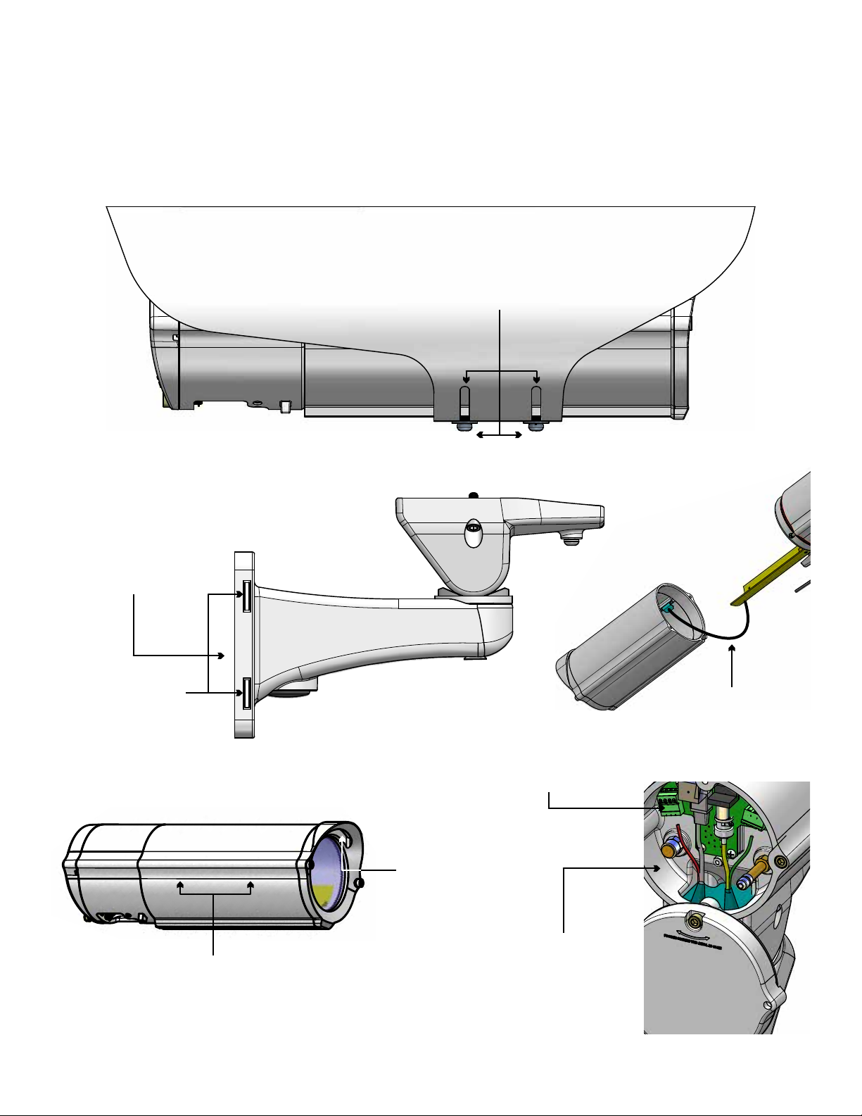
Multi-Plane
Adjustable SunShield
position to protect
against glare on lens
Cable Feed Through
hides and protects cables
Pop Out Tabs
allows for
pole mounting
Durable and Attractive
“grite” color powder coated
nish. (increased corrosion
protection nish available)
Lanyard Cable
safely retains housing
during installation
Installers Connection Board
allows for easy hook-ups
Hand Hold
underlaid grip point
Rear Access Panel
acts as internal J-Box
Page 6

Electrical Specifications
!!
Power 120Vac
Class 2 Only
120Vac: 17 watts Heater (16 watts), Blower (1 watt)
VDS UNITS
Contents of Box
English
Español
Français
Deutsch
Tools Required: Phillips head screwdriver
120Vac: 17 vatios Calentador (16 vatios), soplador (1 vatio)
Herramientas requeridas: Destornillador principal Phillips
120Vac: 17 watts Réchauffeur (16 watts), ventilateur (1 watt)
Outils requis : Tournevis phillips
120Vac: 17 Watt Heizung (16 Watt), Gebläse (1 Watt)
Werkzeuge erfordert: Kreuzkopfschraubenzieher
120Vac: 17 watts Calefator (16 watts), ventilador (1 watt)
Ferramentas exigidas: Chave de fenda principal de Phillips
Midspan
for
Some Models
Hardware Packet
Portuguese
120Vac: 17 watt Riscaldatore (16 watt), ventilatore (1 watt)
Gli attrezzi hanno richiesto: Cacciavite phillips
Italiano
PRESSURIZED MODELS:
115Vac: 17 watts Heater (16 watts), Blower (1 watt)
Tools Required: Phillips head screwdriver
ADDITIONAL DETAIL TO BE UPDATED IN FUTURE REVISIONS
Page 7

Proper Assembly of Mounting Bracket
!!
Wiring Access Holes:
Must be rear facing
CAUTION: When assembling the mounting bracket, make sure
all the wiring access holes are facing towards the rear of the
base mounts access portal.
• PRECAUCIÓN: Al montar la consola de montaje, cerciórese de que todos los agujeros
de acceso del cableado son revestimiento hacia la parte posterior del portal bajo del
acceso de los montajes.
• ATTENTION : En assemblant le support, assurez-vous que toutes les ouvertures
d'accès de câblage sont revêtement vers l'arrière du portail bas d'accès de bâtis.
• VORSICHT: Wenn Sie die Schienenplatte zusammenbauen, stellen Sie sicher, dass alle
VerdrahtungsZugangslöcher Einfassung in Richtung zur Rückseite des niedrigen
Einfassungszugangsportals sind.
• CUIDADO: Ao montar o suporte, certique-se que todos os furos de acesso da ação
são revestimento para a parte traseira do portal baixo do acesso das montagens.
• ATTENZIONE: Nel montare il montaggio - la staffa, si assicura che tutti i fori di
accesso dei collegamenti siano rivestimento verso la parte posteriore del portale
basso di accesso dei supporti.
Recommended Hardware for the Mounting Holes:
• 5/16” - 18 (or M8 for metric) x minimum 1 ¼” Hex Head Bolt
• 5/16” Flat Washer
• 5/16” Lock Washer
Page 8

Attach mount to wall with suitable hardware (not provided).
• Ate el montaje a la pared con el hardware conveniente (no proporcionado).
• Attachez le bâti au mur avec le matériel approprié (non fourni).
• Bringen Sie Einfassung zur Wand mit der verwendbaren Hardware an (nicht bereitgestellt).
• Una a montagem à parede com a ferragem apropriada (não fornecida).
• Attacchi il supporto alla parete con ssaggi adatti (non forniti).
WALL MOUNTING
If attaching to pole, rst break away tabs with pliers and remove
(4) strap plugs.
• Si atan al poste, el primeros rompen lejos lengüetas con los alicates y quitan (4) los enchufes
de la correa.
• Si attachant au poteau, les premiers cassent loin des étiquettes avec des pinces et enlèvent
(4) des prises de courroie.
• Bei der Befestigung zum Pfosten, brechen erste weg Vorsprünge mit Zangen und entfernen
(4) Bügelstecker.
• Se unindo ao pólo, o primeiros quebram afastado abas com alicates e removem (4) plugues
da cinta.
• Se attaccando al palo, i primi rompono via le linguette con le pinze e rimuovono (4) la cinghia
tappa.
TAB
1
If running wire through a conduit to the housing mount, rst install
appropriate ttings to the mount base.
• Si se ejecuta a través de un cable de conducto a la carcasa de montaje, primero instale los
accesorios adecuados para la base de montaje.
• Si vous utilisez le câble dans un conduit à la monture logement, installez d'abord raccords
appropriés à la base de monture.
• Wenn Laufen Draht über eine Leitung mit dem Gehäuse montieren, installieren Sie zuerst
geeignete Armaturen an der Halterung Basis.
• Se você estiver executando o através de um canal para a montagem de habitação, primeiro
instale acessórios apropriados à base de montagem.
• Se l'esecuzione del lo attraverso un condotto al monte degli alloggi, prima installare raccordi
appropriati per la base di montaggio.
2
POLE MOUNTING
3
Mounting Straps Sold Separately
4
Thread straps (not provided) through the mount as shown.
• Pase las correas (no incluidos) a través del soporte como se muestra.
• Sangles de la discussion (non fournies) dans le support comme indiqué.
• Themen-Riemen (nicht mitgeliefert) durch die Halterung wie gezeigt.
• Correias do Tópico (não fornecidos) através da montagem imediata.
• Cinghie di discussione (non in dotazione) attraverso il supporto come illustrato.
Page 9

Pole Mount Option (Use Steel Straps to Mount)
5
Gasket Nipples
6
Crimp
Cable Ties
Cable
Feed cable through bracket, pierce the gasket nipples
(as needed). Place the gasket as shown.
• Alimente el cable a través del soporte, perfore las entrerroscas de la junta (según lo necesitado).
Coloque la junta como se muestra.
• Alimentez le câble par la parenthèse, percez les mamelons de garniture (comme nécessaire).
Placez la garniture comme montrée.
• Ziehen Sie Kabel durch Haltewinkel ein, durchbohren Sie die Dichtungsnippel (wie gebraucht).
Setzen Sie die Dichtung wie gezeigt.
• Alimente o cabo através do suporte, perfure os bocais da gaxeta (como necessário). Coloc a
gaxeta como mostrada.
• Alimenti il cavo tramite la staffa, perfori gli ugelli della guarnizione (come stato necessario).
Disponga la guarnizione come indicata.
Wall Mount Option
7
Crimp
Cable
Crimp the connectors as needed. Then use cable ties
on the nipples to secure device, leave extra cable.
• Prense los conectadores según lo necesitado. Entonces utilice las ataduras de cables en las
entrerroscas para asegurar el dispositivo, dejan el cable adicional.
• Sertissez par replis les connecteurs comme nécessaires. Utilisez alors les serres-câble sur les
mamelons pour xer le dispositif, laissent le câble supplémentaire.
• Quetschverbinden Sie die Verbindungsstücke, wie gebraucht. Benutzen Sie dann Kabelbinder
auf den Nippeln, um Vorrichtung zu sichern, lassen Extrakabel.
• Frise os conectores como necessários. Use então cintas plásticas nos bocais para xar o
dispositivo, deixam o cabo extra.
• Unisca i connettori come stati necessari. Allora utilizzi le fascette ferma-cavo sugli ugelli per
assicurare il dispositivo, lasciano il cavo supplementare.
8
FRONT
HOUSING
Cable
Entry
Cable
Entry
OR
Feed cable through back of bracket or bottom access point.
Then follow instructions from previous block.
• Alimente el cable a través detrás del soporte o del punto de acceso inferior. Entonces siga las
instrucciones del bloque anterior.
• Alimentez le câble à travers en arrière de la parenthèse ou du point d'accès inférieur. Suivez
alors les instructions du bloc précédent .
• Ziehen Sie Kabel durch zurück des Haltewinkels oder des unteren Zugangspunktes ein.
Befolgen Sie dann Anweisungen vom vorhergehenden Block .
• Seja o cabo completamente do suporte ou do ponto de acesso inferior. Siga então instruções
do bloco precedente.
• Alimenti il cavo attraverso indietro della staffa o del punto di accesso inferiore. Allora segua le
istruzioni dal blocco precedente .
(A-Tighten)
(B- If you plan to separate the front
housing keep this screw loose)
Place the housing on the bracket, use the provided captive
screws and the key to mount.
• Coloque la cubierta en el soporte, utilice los tornillos prisioneros proporcionados y la llave
al montaje.
• Placez le logement sur la parenthèse, employez les vis captives fournies et la clef au bâti.
• Setzen Sie das Gehäuse am Haltewinkel, verwenden Sie die zur Verfügung gestellten
Sicherheitsschrauben und den Schlüssel zur Einfassung.
• Coloc a carcaça no suporte, use os parafusos prisioneiros fornecidos e a chave à montagem.
• Disponga l'alloggiamento sulla staffa, usi le viti prigioniere fornite e la chiave al supporto.
Page 10
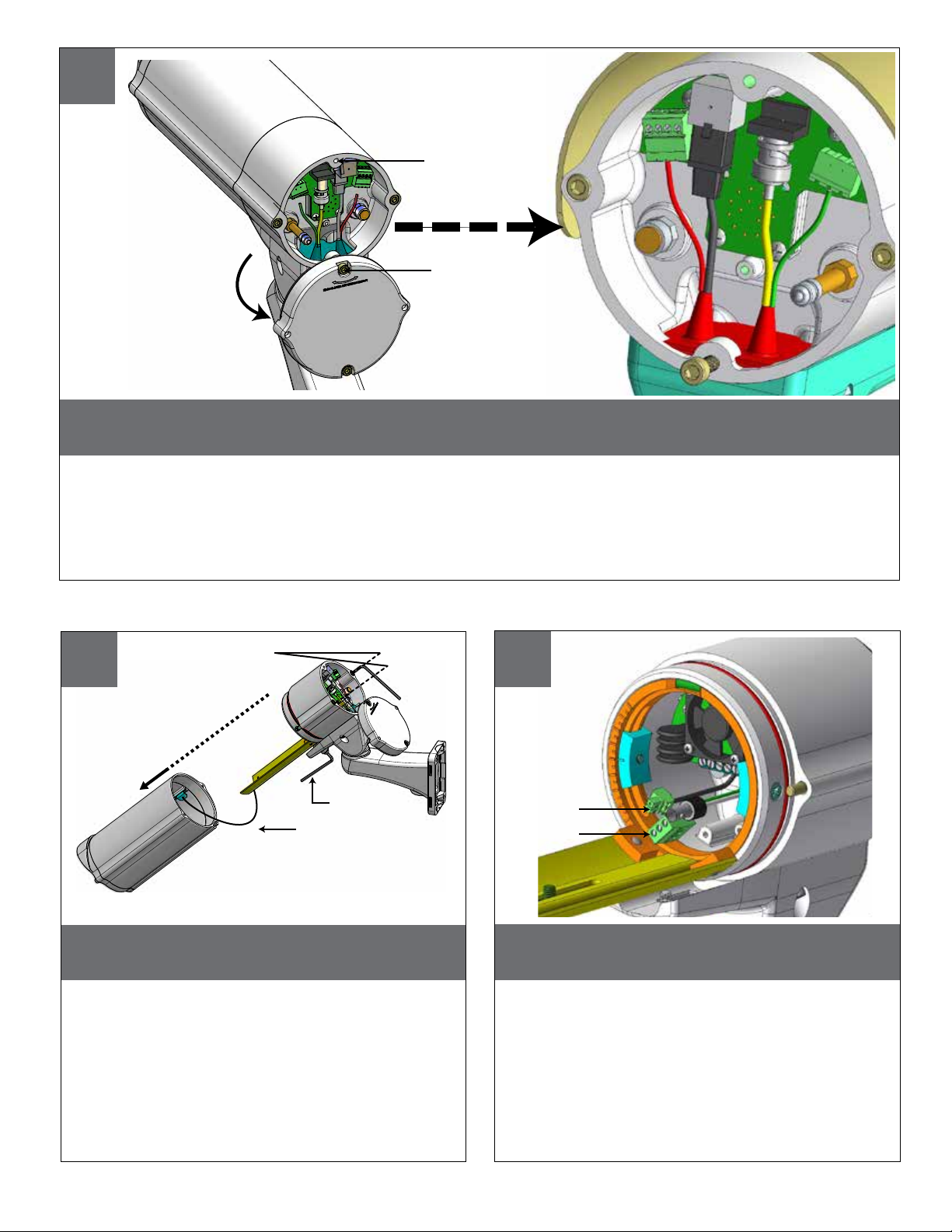
9
(B- Completely loosen)
(A- Slightly loosen)
In order to rotate the rear cover, slightly loosen the screw marked (A) and completely loosen the screw marked (B).
Then make all of the nessecary wiring connections.
• Conecte la tierra entrante con el poste de tierra según lo demostrado.
• Reliez la terre entrante au poteau au sol comme montré.
• Schließen Sie ankommenden Boden an Grundpfosten an, wie gezeigt.
• Conecte a terra entrante ao borne à terra como mostrado.
• Colleghi la terra ricevuta all'alberino al suolo come indicato.
(A) 2 long screws
10
Use Force to Separate the Housing
Key (B) 1 lower screw
Lanyard Cable
Use provided Key to remove the front part of the housing.
• El uso proporcionó llave para quitar la parte delantera de la cubierta.
• L'utilisation a fourni la clef pour enlever la partie avant du logement.
• Gebrauch lieferte Schlüssel, um das Vorderteil des Gehäuses zu entfernen.
• O uso forneceu a chave para remover a parte dianteira da carcaça.
• L'uso ha fornito la chiave per rimuovere la parte anteriore dell'alloggiamento.
(A)
(A)
11
Connectors
Cable
Reference inside view for showing board, ying cables and
attached connectors.
• Reérase dentro de la visión para demostrar el tablero, los cables que vuelan y los
conectadores atados.
• Mettez en référence à l'intérieur de la vue pour montrer le conseil, les câbles volants et
les connecteurs attachés.
• Beziehen Sie innerhalb der Ansicht für das Zeigen des Brettes, der iegenden Kabel und
der angebrachten Verbindungsstücke.
• Proveja dentro da vista para mostrar a placa, cabos de voo e conectores unidos.
• Riferimento all'interno della vista per la mostra bordo, i cavi volanti e dei connettori allegati.
Page 11
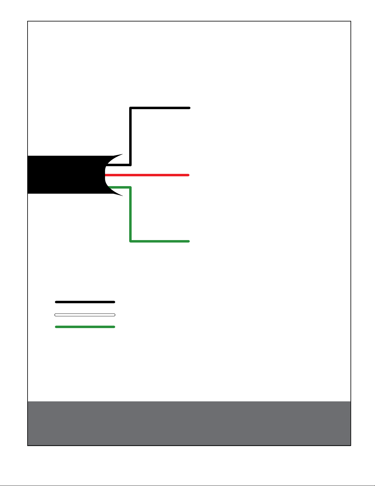
Black - focus
Red - common
Green - zoom
black - line
white - neutral
green - ground
NOTE: (must be connected to
ground for surge protection).
Wiring Diagram
CAUTION: Be sure to securely tighten all ttings to ensure a liquid tight seal. Failure to do so could allow water to enter the housing and damage the camera and lens.
Page 12

12
Camera Sled Ring
13
Screw
Camera Sled
Install the camera using provided screws and rubber spacer, to
center lens (if needed).
• Instale la cámara usando los tornillos proporcionados y el espaciador de goma, a la lente de
centro (si es necesario).
• Installez l'appareil-photo utilisant les vis fournies et l'entretoise en caoutchouc, sur l'objectif
central (si nécessaire).
• Bringen Sie die Kamera unter Verwendung der zur Verfügung gestellten Schrauben und der
Gummidistanzscheibe, zum Mittelobjektiv an (wenn erforderlich).
• Instale a câmera usando os parafusos fornecidos e o espaçador de borracha, à lente center
(se necessário).
• stalli la macchina fotograca usando le viti fornite ed il distanziatore di gomma, all'obiettivo
concentrare (se necessario).
Loosen the screws shown on the picture and turn the camera
sled ring to the desired angle and re-tighten.
• Aoje los tornillos demostrados en el cuadro y dé vuelta al anillo del trineo de la cámara
al ángulo deseado y vuélvalo a apretar.
• Desserrez les vis montrées sur l'image et tournez l'anneau de traîneau d'appareil-photo
à l'angle désiré et le resserrez.
• Lösen Sie die Schrauben, die auf der Abbildung gezeigt werden und drehen Sie den
Kameraschlittenring zum gewünschten Winkel und ziehen Sie wieder an.
• Afrouxe os parafusos mostrados no retrato e gire o anel do trenó da câmera para o ângulo
desejado e reaperte-o.
• Allenti le viti indicate sull'immagine e giri l'anello della slitta della macchina fotograca
nell'angolo voluto e riserri.
Future Maintenance Pressurize the Unit (NOT required for the Dust Tight Unit)
150
200
14 15
580
Fitting
100
50
250
PSI
300
0
Hose
Regulator
Air Chuck
HAND HOLD
The front window can be removed in case the lens
requires adjustment.
• La ventana delantera puede ser quitada en caso de que la lente requiera el ajuste.
• La fenêtre avant peut être enlevée au cas où l'objectif exigerait l'ajustement.
• Das vordere Fenster kann entfernt werden, falls das Objektiv Justage erfordert.
• A janela dianteira pode ser removida caso que a lente exige o ajuste.
• La nestra anteriore può essere rimossa nel caso l'obiettivo richieda la registrazione.
Nitrogen
Tank
When pressurizing unit be sure to set the gauge or regulator
slightly above the housing pressure target of 5-7psi (0.35-0.5bar).
• Al presurizar la unidad esté seguro de jar el calibrador o el regulador levemente
sobre la blanco de la presión de la cubierta de 5-7psi (0.35-0.5bar).
• En pressurisant l'unité soyez sûr de placer la mesure ou le régulateur légèrement
au-dessus de la cible de pression de logement de 5-7psi (0.35-0.5bar).
• Wenn Sie Maßeinheit unter Druck setzen, seien Sie sicher, die Lehre oder den
Regler über das Gehäusedruckziel von 5-7psi (0.35-0.5bar) etwas einzustellen.
• Ao pressurizar a unidade seja certo ajustar ligeiramente o calibre ou o regulador
acima do alvo da pressão da carcaça de 5-7psi (0.35-0.5bar).
• Nel pressurizzare l'unità sia sicuro regolare un po'il calibro o il regolatore sopra
l'obiettivo di pressione dell'alloggiamento di 5-7psi (0.35-0.5bar).
Page 13

Pressurize the Unit Cont.
16
Place the air chuck on the ll valve
and begin lling until pressure relief
valve opens.
• Coloque la tirada del aire en la válvula del tanque y
comience a llenar hasta que la válvula de descarga
de presión se abra.
• Placez le mandrin d'air sur la valve de réservoir et
commencez à remplir jusqu'à ce que la valve de
décompression s'ouvre.
• Setzen Sie die Luftklemme auf das Behälterventil
und fangen Sie an zu füllen, bis Druckablassventil
sich öffnet.
• Coloc o mandril do ar na válvula do tanque e
comece a encher-se até que a válvula de escape de
pressão abra.
• Disponga il mandrino dell'aria sulla valvola del carro
armato e cominci a riempire no a che la valvola
limitatrice della pressione non si apra.
(5-7psi)
Over Relief Valve
17
Pressure Fill Schraeder Valve
Air Chuck
Depress the ll valve. Drain all air
from the housing and repeat 3 times
to remove all moisture.
• Presione la válvula del terraplén. Salga todo el aire
de la cubierta y de la repetición 3 veces de quitar
toda la humedad.
• Enfoncez la valve de sufsance. Évacuez tout l'air le
logement et la répétition 3 fois d'enlever toute
l'humidité.
• Drücken Sie das Fülleventil nieder. Lassen Sie alle
Luft aus dem Gehäuse und der Wiederholung 3mal,
alle Feuchtigkeit zu entfernen ab.
• Comprima a válvula da suciência. Saia todo o ar da
carcaça e da repetição 3 vezes remover toda a
umidade.
• Deprima la valvola del materiale di riempimento.
Tolga tutta l'aria dall'alloggiamento e dalla
ripetizione 3 volte rimuovere tutta l'umidità.
Depress to Purge
Pressure Fill Schraeder Valve
Page 14

18
Connectors
After purging and relling, check
the housings pressure. It should be
around 5-7psi (0.35-0.5bar).
• Después de purgar y de rellenar, compruebe la
presión de las cubiertas. Debe estar alrededor de
5-7psi (0.35-0.5bar).
• Après la purge et le remplissage, vériez la pression
de logements. Elle devrait être autour de 5-7psi
(0.35-0.5bar).
• Nachdem Sie bereinigt haben und wieder gefüllt
haben überprüfen Sie den Gehäusedruck. Er sollte
um 5-7psi (0.35-0.5bar) sein.
• Após a remoção e o reenchimento, veric a pressão
das carcaças. Deve ser em torno de 5-7psi
(0.35-0.5bar).
• Dopo l'eliminazione dell'inceppo ed il riempimento,
controlli la pressione degli alloggiamenti. Dovrebbe
essere intorno a 5-7psi (0.35-0.5bar).
Over - Pressure Relief Valve
Replacement Parts List
3
2
1
5
6
PFH10
4
15
20
10
25
5
PSI
30
0
Fill Valve
Air Chuck
12
7
11
8
13
14
Pressure Gauge
NOT INCLUDED
15
16
17
11
DESCRIPTION PART #
9
1 RPVL3857 BACK COVER
2
RPVL3863
3
RPVALV12
BACK COVER GASKET
TANK VALVE
4 RPCA3682 CONNECTION BOARD
5 RPPFHPCK HARDWARE PACKET
6 RPVALV08 PRESSURE RELIEF VALVE
7 RPVL2968 HOUSING BODY
8 RPGK3880 WALL MOUNT GASKET
9 RPVL3858 HOUSING BRACKET
10 RPFTM2425G WALL MOUNT BRACKET
10
11 RPRSORG24 HOUSING ORING
12 RPVL3860 HOUSING NUT
13 RP76VL2015 PC BOARD
14 RPVL2969 CAMERA SLED ASSEMBLY
15 RPVL2965 HOUSING ASSEMBLY
16 RPVL3888 LANYARD SLED
17 RPVL2972 FRONT WINDOW ASSEMBLY
 Loading...