

Page 1
For the mobile version of this guide, see:
animatics.com/docs/guides-html/c5_dmx/
Page 2

Copyright Notice
©2014-2019, Moog Inc., Animatics.
Moog Animatics Class 5 SmartMotor™ DMX Guide, Rev. C, PN: SC80100004-001.
This manual, as well as the software described in it, is furnished under license and may be
used or copied only in accordance with the terms of such license. The content of this manual is
furnished for informational use only, is subject to change without notice and should not be
construed as a commitment by Moog Inc., Animatics. Moog Inc., Animatics assumes no
responsibility or liability for any errors or inaccuracies that may appear herein.
Except as permitted by such license, no part of this publication may be reproduced, stored in a
retrieval system or transmitted, in any form or by any means, electronic, mechanical,
recording, or otherwise, without the prior written permission of Moog Inc., Animatics.
The programs and code samples in this manual are provided for example purposes only. It is
the user's responsibility to decide if a particular code sample or program applies to the
application being developed and to adjust the values to fit that application.
Moog Animatics and the Moog Animatics logo, SmartMotor and the SmartMotor logo,
Combitronic and the Combitronic logo are all trademarks of Moog Inc., Animatics.
Please let us know if you find any errors or omissions in this manual so that we can improve it
for future readers. Such notifications should contain the words "DMX Guide" in the subject line
and be sent by e-mail to: animatics_marcom@moog.com. Thank you in advance for your
contribution.
Contact Us:
Americas - West
Moog Animatics
2581 Leghorn Street
Mountain View, CA 94043
USA
Tel: 1 650-960-4215 Tel: 1 610-328-4000 x3999
Support: 1 (888) 356-0357
Website: www.animatics.com
Email: animatics_sales@moog.com
Americas - East
Moog Animatics
750 West Sproul Road
Springfield, PA 19064
USA
Fax: 1 610-605-6216
Page 3

Table Of Contents
Introduction 5
Purpose 6
Combitronic Technology 6
DMX Overview 8
Safety Information 9
Safety Symbols 9
Other Safety Considerations 9
Motor Sizing 9
Environmental Considerations 9
Machine Safety 10
Documentation and Training 11
Additional Equipment and Considerations 11
Safety Information Resources 11
Additional Documents 13
Related Guides 13
Other Documents 13
Additional Resources 14
DMX Resources 14
Connections, Wiring and Status LEDs 15
Connectors and Pinouts 16
D-Style Motors: Connectors and Pinouts 16
M-Style Motors: Connectors and Pinouts 17
DMX NetworkTopology 17
System Cable Diagram 18
D-Style Multidrop Signal Cable Diagram 19
M-Style Multidrop Signal Cable Diagram 20
Understanding the Status LEDs 21
DMX on the SmartMotor 22
DMXImplementation 23
Data Storage and Usage 23
Example 24
Status Bits 25
End of Packet 25
DMXCommands 27
Moog Animatics Class 5 SmartMotor™ DMX Guide,Rev. C
Page 3 of 46
Page 4

Select DMX Channels 27
Special Range Checking 28
Open DMX Channel 28
Close DMX Channel 28
Example Programs 29
Home Against a Hard Stop Example 30
Position Mode Control Example 32
DMX Five Channel Example 35
DMX Packet Test Example 38
Reverse DMXChannel Byte Order Example 40
Troubleshooting 43
Moog Animatics Class 5 SmartMotor™ DMX Guide,Rev. C
Page 4 of 46
Page 5

Introduction
Introduction
This chapter provides an overview of the DMX features provided by the Moog Animatics
SmartMotor. It also provides information on safety, and where to find related documents and
additional resources.
Purpose 6
Combitronic Technology 6
DMX Overview 8
Safety Information 9
Safety Symbols 9
Other Safety Considerations 9
Motor Sizing 9
Environmental Considerations 9
Machine Safety 10
Documentation and Training 11
Additional Equipment and Considerations 11
Safety Information Resources 11
Additional Documents 13
Related Guides 13
Other Documents 13
Additional Resources 14
DMX Resources 14
Moog Animatics Class 5 SmartMotor™ DMX Guide,Rev. C
Page 5 of 46
Page 6

Purpose
Purpose
This manual explains the Moog Animatics Class 5 SmartMotor™ support for the Digital
MultipleX (DMX) communications protocol. It describes the major concepts that must be
understood to integrate a SmartMotor as a DMX slave device. However, it only minimally
covers the low-level details of the DMX protocol.
NOTE: The Remote Device Management (RDM) bidirectional communication
extension of the DMX protocol is not supported.
The feature set described in this version of the manual refers to firmware in the 5.x.4.y
series, where x = 0, 16, 32, 97 or 98, and y=3 or greater. Versions 5.0.4, 5.16.4, and 5.32.4
are specific to D-style motors, and versions 5.97.4 and 5.98.4 are specific to M-style motors.
Refer to the following lists.
NOTE: The SmartMotor firmware must be one of the listed versions.
For D-style motors:
l
5.0.4.y (where y is 3 or greater)
l
5.16.4.y (where y is 3 or greater)
l
5.32.4.y (where y is 3 or greater)
For M-style motors:
l
5.97.4.y (where y is 3 or greater)
l
5.98.4.y (where y is 3 or greater)
This manual is intended for programmers or system developers who have read and
understand the Engineering Commission of United States Institute for Theatre Technology
(USITT) DMX512-A standard. Therefore, this manual is not a tutorial on that standard or the
DMX protocol. Instead, it should be used to understand the specific implementation details for
the Moog Animatics Class 5 SmartMotor. Additionally, code examples are provided to assist
the programmer with the SmartMotor integration.
The Command Reference section of this manual includes details about the specific DMX
commands available in the SmartMotor through the DMX firmware. For details, see
DMXCommands on page 27.
Combitronic Technology
The most unique feature of the SmartMotor is its ability to communicate with other
SmartMotors and share resources using Moog Animatics’ Combitronic™ technology.
Combitronic is a protocol that operates over a standard CAN interface. It may coexist with
CANopen and other protocols. It requires no single dedicated master to operate. Each
SmartMotor connected to the same network communicates on an equal footing, sharing all
information, and therefore, sharing all processing resources.
While the Combitronic protocol can be used in parallel with a DMX network, there are certain
restrictions:
l
The DMX wiring does not carry the Combitronic signal. Therefore, additional cabling
(available from Moog Animatics) must be used to build the Combitronic network.
Moog Animatics Class 5 SmartMotor™ DMX Guide,Rev. C
Page 6 of 46
Page 7

Combitronic Technology
l
There is bidirectional, end-to-end connectivity only within the same Combitronic
network of motors. Therefore, one Combitronic network cannot communicate with
another.
When a Combitronic network is used in parallel with a DMXnetwork, you can:
l
Avoid the cost of repeaters.
l
Gain bidirectional, end-to-end connectivity within the Combitronic network of motors.
There are no other motors on the market that can talk to each other on a side bus while
being a slave to the DMX host controller.
l
Compute or synchronize motion between motors within the same Combitronic network.
For example, DMX values (from the host controller) could be used to adjust amplitude
and frequency of SmartMotor Cam tables for an electronic camming or gearing
application that controls the motion pattern of a bank of stage lights.
In short, DMX-equipped SmartMotors retain all the features and benefits of the standard Class
5 SmartMotor, including features like electronic camming, gearing, and Combitronic support.
For additional details, see the Class 5 SmartMotor™ Installation & Startup Guide.
Moog Animatics Class 5 SmartMotor™ DMX Guide,Rev. C
Page 7 of 46
Page 8
DMX Overview
0 1 2 3 4 5 6 7 1 2
Start code and data channels
(11 bits, 4 μs each )
DATA BITS
STOP
BITS
START
BIT
IDLE
START
BREAK
100 μs
(could be as
low as 92 μs)
12
μs
MAB
Start Code in Slot 0
(followed by up to 512 data channels)
SLOT 0
44 μs
SLOT 1
44 μs
SLOT 2
44 μs
SLOT 3
44 μs
SLOT 4
44 μs
SLOT 5
44 μs
SLOT 6
44 μs
DMX Overview
DMX is a standard for digital communications networks that are used to control lighting, stage
effects, dimmers, fog machines and related applications. This control may include positioning
and/or focusing of lights or other objects to aid in visual effects of stage productions or other
live events. As a result, its use is often expanded to the movement or control of curtains,
stage props or other objects that require motion.
DMX, or further expanded as DMX512, is an EIA-485 (RS-485) hardware-based protocol that is
unidirectional in nature — the controller only sends data; it does not receive data. Further, it
has no error checking or checksums that are required for use in hazardous applications.
Therefore, its use must be limited to safe operating environments where failure due to
transmission errors would not cause harm to personnel or equipment.
WARNING: DMX networks must not be used in applications where failure due
to transmission errors would cause harm to personnel or equipment.
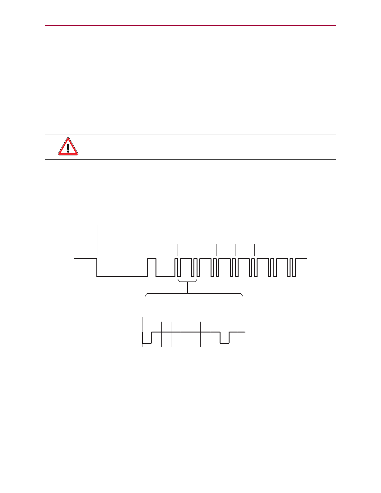
DMX512 controllers transmit asynchronous serial data at 250 kilobaud (kBd). The data format
is fixed and begins with a single start bit, eight data bits, and two stop bits with no parity. Up
to 512 8-bit data bytes or "channels" of data may be transmitted to all nodes at once. The data
is ordered serially and typically runs continuously from a DMX master controller. The full data
packet begins with a break, followed by a Mark after Break (MAB), then Slot 0 beginning with
a one-byte Start Code, and that is followed by up to 512 data slots. Refer to the following
figure.
Moog Animatics Class 5 SmartMotor™ DMX Guide,Rev. C
DMX Data Transmission
Page 8 of 46
Page 9
Safety Information
Safety Information
This section describes the safety symbols and other safety information.
Safety Symbols
The manual may use one or more of the following safety symbols:
WARNING: This symbol indicates a potentially nonlethal mechanical hazard,
where failure to follow the instructions could result in serious injury to the
operator or major damage to the equipment.
CAUTION: This symbol indicates a potentially minor hazard, where failure to
follow the instructions could result in slight injury to the operator or minor
damage to the equipment.
NOTE: Notes are used to emphasize non-safety concepts or related information.
Other Safety Considerations
The Moog Animatics SmartMotors are supplied as components that are intended for use in an
automated machine or system. As such, it is beyond the scope of this manual to attempt to
cover all the safety standards and considerations that are part of the overall machine/system
design and manufacturing safety. Therefore, the following information is intended to be used
only as a general guideline for the machine/system designer.
It is the responsibility of the machine/system designer to perform a thorough "Risk
Assessment" and to ensure that the machine/system and its safeguards comply with the
safety standards specified by the governing authority (for example, ISO, OSHA, UL, etc.) for
the locale where the machine is being installed and operated. For more details, see Machine
Safety on page 10.
Motor Sizing
It is the responsibility of the machine/system designer to select SmartMotors that are
properly sized for the specific application. Undersized motors may: perform poorly, cause
excessive downtime or cause unsafe operating conditions by not being able to handle the
loads placed on them. The System Best Practices document, which is available on the Moog
Animatics website, contains information and equations that can be used for selecting the
appropriate motor for the application.
Replacement motors must have the same specifications and firmware version used in the
approved and validated system. Specification changes or firmware upgrades require the
approval of the system designer and may require another Risk Assessment.
Environmental Considerations
It is the responsibility of the machine/system designer to evaluate the intended operating
environment for dust, high-humidity or presence of water (for example, a food-processing
environment that requires water or steam wash down of equipment), corrosives or chemicals
that may come in contact with the machine, etc. Moog Animatics manufactures specialized
Moog Animatics Class 5 SmartMotor™ DMX Guide,Rev. C
Page 9 of 46
Page 10

Machine Safety
IP-rated motors for operating in extreme conditions. For details, see the Moog Animatics
Product Catalog.
Machine Safety
In order to protect personnel from any safety hazards in the machine or system, the
machine/system builder must perform a "Risk Assessment", which is often based on the ISO
13849 standard. The design/implementation of barriers, emergency stop (E-stop)
mechanisms and other safeguards will be driven by the Risk Assessment and the safety
standards specified by the governing authority (for example, ISO, OSHA, UL, etc.) for the
locale where the machine is being installed and operated. The methodology and details of
such an assessment are beyond the scope of this manual. However, there are various sources
of Risk Assessment information available in print and on the internet.
NOTE: The following list is an example of items that would be evaluated when
performing the Risk Assessment. Additional items may be required. The safeguards
must ensure the safety of all personnel who may come in contact with or be in the
vicinity of the machine.
In general, the machine/system safeguards must:
l
Provide a barrier to prevent unauthorized entry or access to the machine or system. The
barrier must be designed so that personnel cannot reach into any identified danger
zones.
l
Position the control panel so that it is outside the barrier area but located for an
unrestricted view of the moving mechanism. The control panel must include an E-stop
mechanism. Buttons that start the machine must be protected from accidental
activation.
l
Provide E-stop mechanisms located at the control panel and at other points around the
perimeter of the barrier that will stop all machine movement when tripped.
l
Provide appropriate sensors and interlocks on gates or other points of entry into the
protected zone that will stop all machine movement when tripped.
l
Ensure that if a portable control/programming device is supplied (for example, a handheld operator/programmer pendant), the device is equipped with an E-stop mechanism.
NOTE: A portable operation/programming device requires many additional
system design considerations and safeguards beyond those listed in this
section. For details, see the safety standards specified by the governing
authority (for example, ISO, OSHA, UL, etc.) for the locale where the
machine is being installed and operated.
l
Prevent contact with moving mechanisms (for example, arms, gears, belts, pulleys,
tooling, etc.).
l
Prevent contact with a part that is thrown from the machine tooling or other parthandling equipment.
l
Prevent contact with any electrical, hydraulic, pneumatic, thermal, chemical or other
hazards that may be present at the machine.
l
Prevent unauthorized access to wiring and power-supply cabinets, electrical boxes, etc.
Moog Animatics Class 5 SmartMotor™ DMX Guide,Rev. C
Page 10 of 46
Page 11

Documentation and Training
l
Provide a proper control system, program logic and error checking to ensure the safety
of all personnel and equipment (for example, to prevent a run-away condition). The
control system must be designed so that it does not automatically restart the
machine/system after a power failure.
l
Prevent unauthorized access or changes to the control system or software.
Documentation and Training
It is the responsibility of the machine/system designer to provide documentation on safety,
operation, maintenance and programming, along with training for all machine operators,
maintenance technicians, programmers, and other personnel who may have access to the
machine. This documentation must include proper lockout/tagout procedures for maintenance
and programming operations.
It is the responsibility of the operating company to ensure that:
l
All operators, maintenance technicians, programmers and other personnel are tested
and qualified before acquiring access to the machine or system.
l
The above personnel perform their assigned functions in a responsible and safe manner
to comply with the procedures in the supplied documentation and the company safety
practices.
l
The equipment is maintained as described in the documentation and training supplied by
the machine/system designer.
Additional Equipment and Considerations
The Risk Assessment and the operating company's standard safety policies will dictate the
need for additional equipment. In general, it is the responsibility of the operating company to
ensure that:
l
Unauthorized access to the machine is prevented at all times.
l
The personnel are supplied with the proper equipment for the environment and their job
functions, which may include: safety glasses, hearing protection, safety footwear,
smocks or aprons, gloves, hard hats and other protective gear.
l
The work area is equipped with proper safety equipment such as first aid equipment,
fire suppression equipment, emergency eye wash and full-body wash stations, etc.
l
There are no modifications made to the machine or system without proper engineering
evaluation for design, safety, reliability, etc., and a Risk Assessment.
Safety Information Resources
Additional SmartMotor safety information can be found on the Moog Animatics website; open
the file "109_Controls, Warnings and Cautions.pdf" located at:
http://www.animatics.com/support/moog-animatics-catalog.html
OSHA standards information can be found at:
https://www.osha.gov/law-regs.html
ANSI-RIA robotic safety information can be found at:
http://www.robotics.org/robotic-content.cfm/Robotics/Safety-Compliance/id/23
Moog Animatics Class 5 SmartMotor™ DMX Guide,Rev. C
Page 11 of 46
Page 12

Safety Information Resources
UL standards information can be found at:
http://ulstandards.ul.com/standards-catalog/
ISOstandards information can be found at:
http://www.iso.org/iso/home/standards.htm
EUstandards information can be found at:
http://ec.europa.eu/growth/single-market/european-standards/harmonisedstandards/index_en.htm
Moog Animatics Class 5 SmartMotor™ DMX Guide,Rev. C
Page 12 of 46
Page 13

Additional Documents
Additional Documents
The Moog Animatics website contains additional documents that are related to the information
in this manual. Please refer to the following list.
Related Guides
l
Class 5 SmartMotor™ Installation & Startup Guide
http://www.animatics.com/cl-5-install-startup-guide
l
SmartMotor™ Developer's Guide
http://www.animatics.com/smartmotor-developers-guide
Other Documents
l
SmartMotor™ System Best Practices
http://www.animatics.com/system-best-practices-application-note
l
SmartMotor™ Product Certificate of Conformance
http://www.animatics.com/download/Declaration of Conformity.pdf
l
SmartMotor™ ULCertification
http://www.animatics.com/download/MA_UL_online_listing.pdf
l
SmartMotor Developer's Worksheet
(interactive tools to assist developer: Scale Factor Calculator, Status Words, CAN Port
Status, Serial Port Status, RMODE Decoder and Syntax Error Codes)
http://www.animatics.com/tools
l
Moog Animatics Product Catalog
http://www.animatics.com/support/moog-animatics-catalog.html
Moog Animatics Class 5 SmartMotor™ DMX Guide,Rev. C
Page 13 of 46
Page 14

Additional Resources
Additional Resources
The Moog Animatics website contains useful resources such as product information,
documentation, product support and more. Please refer to the following addresses:
l
General company information:
http://www.animatics.com
l
Product information:
http://www.animatics.com/products.html
l
Product support (Downloads, How To videos, Forums, Knowledge Base, and FAQs):
http://www.animatics.com/support.html
l
Sales and distributor information:
http://www.animatics.com/sales-offices.html
l
Application ideas (including videos and sample programs):
http://www.animatics.com/applications.html
DMX Resources
The following equipment and software can be used to test your DMX system:
l
DMX512 Standard:
http://old.usitt.org/DMX512.aspx
l
Lights Up software (open source, GNUlicense):
http://lightsup.sourceforge.net/
l
Enttec Open DMX USB interface:
http://www.enttec.com/?main_menu=Products&pn=70303
Moog Animatics Class 5 SmartMotor™ DMX Guide,Rev. C
Page 14 of 46
Page 15

Connections, Wiring and Status LEDs
Connections, Wiring and Status LEDs
This chapter provides information on the SmartMotor connectors, a multidrop cable diagram,
and a description of the SmartMotor status LEDs.
Connectors and Pinouts 16
D-Style Motors: Connectors and Pinouts 16
M-Style Motors: Connectors and Pinouts 17
DMX NetworkTopology 17
System Cable Diagram 18
D-Style Multidrop Signal Cable Diagram 19
M-Style Multidrop Signal Cable Diagram 20
Understanding the Status LEDs 21
Moog Animatics Class 5 SmartMotor™ DMX Guide,Rev. C
Page 15 of 46
Page 16

Connectors and Pinouts
PIN
1
2
3
4
5
NC
+V (NC except DeviceNet)
-V (Isolated GND )
CAN-H
CAN-L
DESCRIPTION
5-Pin CAN (female)
1
2
3
4
5
6
7
8
9
10
11
12
I/O-16 GP
I/O-17 GP
I/O-18 GP
I/O-19 GP
I/O-20 GP
I/O-21 GP
I/O-22 GP
I/O-23 GP
I/O-24 GP
I/O-25 GP
+24VDC Input
GND I/O
PIN DESCRIPTION
12-Pin Expanded I/O Connector
1
2
3
4
5
6
7
8
9
10
11
12
13
14
15
I/O-0
I/O-1
I/O-2
I/O-3
I/O-4
I/O-5
I/O-6
Encoder A Out
Encoder B Out
RS-232 Transmit
RS-232 Receive
+5VDC Out
Ground
Power Ground
Power
PIN DESCRIPTION
7-Pin Combo D-Sub Power & I/O
A1 A2
1 2
3 4 5
A1
A2
1
2
3
4
5
+20V to +48V DC
Power Ground
I/O-6
+5VDC Out
RS-232 Transmit
RS-232 Receive
RS-232 Ground
PIN DESCRIPTION
15-Pin D-Sub I/O
Trajectory LED
PWR/Servo LED
CAN Fault LED
CAN Status LED
15 14 13 12 11 10 9
8 7 6 5 4 3 2 1
Connectors and Pinouts
D-Style Motors: Connectors and Pinouts
NOTE: DMX support is on RS-485 "COM1"; it uses pins 5 and 6 of the 15-pin D-Sub
I/O connector (see the following figure). Also, see D-Style Multidrop Signal Cable
Diagram on page 19.
The following figure provides a brief overview of the connectors and pinouts available on the
D-style SmartMotors. For details, see the Class 5 SmartMotor™ Installation & Startup Guide.
NOTE: On the SmartMotor, the RS-485 line labeled "A" is the non-inverting line
(D+). This may be different than other systems where "B" is the non-inverting line.
NOTE: The DE power option is recommended. For details, see the Class 5
SmartMotor™ Installation & Startup Guide.
Moog Animatics Class 5 SmartMotor™ DMX Guide,Rev. C
Page 16 of 46
Page 17

M-Style Motors: Connectors and Pinouts
PIN
1
2
3
4
5
+24VDC Out
I/O-3 or -Limit
GND-Common
I/O-2 or +Limit
I/O-10
DESCRIPTION
LIMIT INPUTS
PIN
1
2
3
4
5
NC
+V (NC except DeviceNet)
-V (Unisolated Ground)
CAN-H
CAN-L
DESCRIPTION
CANOPEN
1
2
3
4
5
6
7
8
9
10
11
12
I/O-0
I/O-1
I/O-4
I/O-5
I/O-6
I/O-7
I/O-8
I/O-9
Not Fault Out
Drive Enable In
+24VDC Out
GND-Common
PIN
I/Os
1
2
3
4
5
6
7
8
GND-Common
RS-485B CH0
RS-485A CH0
ENC A+ (In/Out)
ENC B- (In/Out)
ENC A- (In/Out)
+5VDC Out
ENC B+ (In/Out)
PIN
DESCRIPTION
COMMUNICATION
1
2
3
4
Control Power In 24Vmax
Chassis GND/Earth
GND-Common
Amplifier Power 48Vmax
PIN DESCRIPTION
POWER INPUT
RS-485 serial communication uses a
voltage dierential signal. Appropriate
terminating resistors should be included
on the RS-485 network to ensure reliable
performance.
DESCRIPTION
CANOPEN
RUN LED
12-Pin I/O
4-Pin Power Input
8-Pin
COM Encoder Bus
5-Pin CANopen
(female is standard)
5-Pin
Limit Inputs
CANOPEN
ERROR LED
TRAJECTORY
LED
SERVO-AMPLIFIER
LED
M-Style Motors: Connectors and Pinouts
NOTE: DMX support is on RS-485 "COM0"; it uses pins 2 and 3 of the 8-Pin
COMEncoder Bus connector (see the following figure). Also, see M-Style Multidrop
Signal Cable Diagram on page 20.
The following figure provides a brief overview of the connectors and pinouts available on the
M-style SmartMotors. For details, see the Class 5 SmartMotor™ Installation & Startup Guide.
NOTE: On the SmartMotor, the RS-485 line labeled "A" is the non-inverting line
(D+). This may be different than other systems where "B" is the non-inverting line.
DMX NetworkTopology
As mentioned previously, DMX512 is based on the EIA-485 standard. It comes with all the
limits and requirements of a system based on an RS-485 multi-drop bus. Further, there must
be proper bus termination, as required by the EIA-485 standard. Refer to the following figure.
The EIA-485-A standard for the physical connection allows a length of 1000 feet at 250 kBd.
However, Moog Animatics does not guarantee this distance under all conditions. The user is
responsible for testing and verifying operation in the application environment, including: wire
length, DMX host device, and number of DMX nodes.
At the opposite end from the DMX controller, a 120 Ohm bus terminator must be used (see the
following figure) — this prevents reflected impedance and noise issues that would otherwise
occur.
CAUTION: The 120 Ohm terminator is required at the end of the bus opposite
the DMX controller.
Moog Animatics Class 5 SmartMotor™ DMX Guide,Rev. C
Page 17 of 46
Page 18

System Cable Diagram
DMX512
Controller
(Master)
OUT
Serial IN/OUT
SmartMotor
(Slave)
120 Ohm
Terminator
Serial IN/OUT
SmartMotor
(Slave)
Serial IN/OUT
SmartMotor
(Slave)
DMX Light Console
SmartMotor
Address: 001
120 Ohm
Terminator
SmartMotor
Address: 002
SmartMotor
Address: 003
SmartMotor
Address: 004
One or more stage props are raised/lowered based on inputs from DMX console
DMX Network Topology
NOTE: Any drops from the main bus should be kept as short as possible, so the
system looks like an "in line" network, as shown in the previous figure.
Each DMX network is called a "universe" and can consist of up to 512 data bytes. If more than
512 data bytes are required, then another universe will be required.
NOTE: Some large DMX controllers (such as an operator console) have multiple
outputs, which allow them to control multiple universes.
For example, the following figure shows a DMX network of SmartMotors being used to
raise/lower one or more stage props based on inputs from the DMX controller. Each motor is
assigned a unique DMX address, so it can be operated from the DMX control console. Also,
note the 120 Ohm terminator, which is required at the end of the bus.
DMXand SmartMotors Controlling Stage Props
System Cable Diagram
As shown in the previous section, DMX networks are most reliable when a straight bus is used.
Common problems with DMX bus wiring are often traced to branches or other configurations.
These often create multipath signal reflections that cause communication errors. Adhere to
the following cabling requirements:
l
The maximum cable length should not exceed 1000 feet at 250 kBd.
Moog Animatics Class 5 SmartMotor™ DMX Guide,Rev. C
Page 18 of 46
Page 19

D-Style Multidrop Signal Cable Diagram
Motor as Terminating Node
NOTE: A terminating resistor is required at the downstream end of the bus!
I/O Connector
Pin Numbers
Trajectory
LED (Bt)
Power/Servo
LED
120 Ohm Shunt
Shield Drain (optional)
15 14 13 12 11 10 9
8 7 6 5 4 3 2 1
Shield Drain (optional)
Pin 5 “A” (D+)
Pin 6 “B” (D-)
120 Ohm Shunt
15-pin D-sub Male
Terminating Node
15-pin D-sub Male 15-pin D-sub Male 15-pin D-sub Male
1
2
3
4
5
6
7
8
9
10
11
12
13
14
15
1
23456
789
10
11
12
131415
1
23456
789
10
11
12
131415
1
2
3
4
5
6
7
8
9
10
11
12
13
14
15
Pin 5 “A” (D+)
Pin 6 “B” (D-)
CAUTION: The EIA-485-A standard for the physical connection allows a length
of 1000 feet at 250 kBd. However, Moog Animatics does not guarantee this
distance under all conditions. The user is responsible for testing and verifying
operation in the application environment, including: wire length, DMX host
device, and number of DMX nodes.
l
Each slave must be inline or a short drop from the main bus; do not use branches.
l
Use a 120 Ohm terminator at the downstream end of the bus, which is the end opposite
the DMX512 controller.
CAUTION: The 120 Ohm terminator is required at the downstream end of the
bus.
D-Style Multidrop Signal Cable Diagram
The following figure shows a multidrop signal cable configuration for D-style motors. To
supply power, it is recommended that you use the DE power option. For details, see the Class
5 SmartMotor™ Installation & Startup Guide.
NOTE: DMX support is on RS-485 "COM1"; it uses pins 5 and 6 of the 15-pin D-Sub
I/O connector.
NOTE: On the SmartMotor, the RS-485 line labeled "A" is the non-inverting line
(D+). This may be different than other systems where "B" is the non-inverting line.
D-Style Multidrop Cable Diagram
Moog Animatics Class 5 SmartMotor™ DMX Guide,Rev. C
Page 19 of 46
Page 20

M-Style Multidrop Signal Cable Diagram
Motor as Terminating Node
NOTE: A terminating resistor is required at the downstream end of the bus!
120 Ohm Shunt
Shield Drain (optional)
Shield Drain (optional)
Pin 3 “A” (D+)
Pin 2 “B” (D-)
120 Ohm Shunt
Terminating Node
Pin 3 “A” (D+)
Pin 2 “B” (D-)
CANOPEN
RUN LED
4-Pin Power Input
8-Pin
COM Encoder Bus
CANOPEN
ERROR LED
TRAJECTORY
LED
SERVO-AMPLIFIER
LED
M-Style Multidrop Signal Cable Diagram
The following figure shows a multidrop signal cable configuration for M-style motors. Power is
supplied through the separate 4-Pin Power Input connector. For details, see the Class 5
SmartMotor™ Installation & Startup Guide.
NOTE: DMX support is on RS-485 "COM0"; it uses pins 2 and 3 of the 8-Pin
COMEncoder Bus connector.
NOTE: On the SmartMotor, the RS-485 line labeled "A" is the non-inverting line
(D+). This may be different than other systems where "B" is the non-inverting line.
M-Style Multidrop Signal Cable Diagram
Moog Animatics Class 5 SmartMotor™ DMX Guide,Rev. C
Page 20 of 46
Page 21

Understanding the Status LEDs
P3 (CANopen option)
LED Status on Power-Up:
• With no program and the travel limits are low:
LED 0 will be solid red indicating the motor is in a fault state due to travel limit fault.
LED 1 will be off.
• With no program and the travel limits are high:
LED 0 will be solid red for 500 milliseconds and then begin flashing green.
LED 1 will be off.
• With a program that only disables travel limits and nothing else:
LED 0 will be solid red for 500 milliseconds and then begin flashing green.
LED 1 will be off.
P1 (Power Input)
LED 0
LED 1
P2 (COM
Encoder Bus)
P3
(I/O Connector)
P4
(Limit Inputs)
P5
(CANopen)
LED 3
LED 2
LED 0: Drive Status Indicator
Off No Power
Solid green Drive On
Flashing green Drive Off
Flashing red Watchdog Fault
Solid red Major Fault
Alt. red/green In Boot Load, Needs Firmware
LED 1: Trajectory Status Indicator
Off Not Busy
Solid green Drive On, Trajectory In Progress
LED 2: CAN Bus Network Fault (Red LED)
Off No Error
Single flash At Least One Error
Exceeded Limit
Double flash Heartbeat or Guard Error
Solid Busy Off State
LED 3: CAN Bus Network Status (Green LED)
Blinking Pre-Operational State
(during boot-up)
Solid Normal Operation
Single Device is in Stopped State
Understanding the Status LEDs
The Status LEDs provide the same functionality for the D-style and M-style (including IPsealed) SmartMotors.
Moog Animatics Class 5 SmartMotor™ DMX Guide,Rev. C
Page 21 of 46
Page 22

DMX on the SmartMotor
DMX on the SmartMotor
This chapter provides information about DMX operation on the SmartMotor.
DMXImplementation 23
Data Storage and Usage 23
Example 24
Status Bits 25
End of Packet 25
DMXCommands 27
Select DMX Channels 27
Special Range Checking 28
Open DMX Channel 28
Close DMX Channel 28
Moog Animatics Class 5 SmartMotor™ DMX Guide,Rev. C
Page 22 of 46
Page 23

DMXImplementation
DMXImplementation
The SmartMotor has the ability to accept DMX512 protocol through the RS-485 port. Flexibility
is maintained by allowing the user to assign and accept multiple slots of incoming DMX
protocol — the starting slot and number of slots may be defined by the user.
DMX data packets are unsigned 8-bit integer data. As a result, and to conform to only positive
integer values, incoming slots of 8-bit data are stored into 16-bit signed array variables in
SmartMotor memory.
SmartMotors have predefined 16-bit array data variables consisting of aw[0] through aw
[101]. Therefore, the SmartMotor is limited to 102 DMX channels. The "aw" stands for "array
word" and is an indexed 16-bit signed integer value. If a slot is assigned to an aw[] array
variable, the value returned will be between 0 and 255. This assures proper sign convention
for all values. It also allows for easier addition and bit shifting to optimize incoming data.
NOTE: The SmartMotor is limited to 102 DMX channels.
The user program must read incoming DMX data in the aw[] registers and perform all actions
from that data, including motion and/or digital outputs.
For example, if you want to control the position of a theater light, you would:
1.
Select an unused DMX controller channel,
2.
Program the base address in the SmartMotor aligned with that particular channel,
3.
Write a program that reads the corresponding array variable in the SmartMotor,
4.
Assign corresponding parameters in the motor, including position, velocity, acceleration
and torque, call out a specific subroutine, and more.
By using the SmartMotor, the entire motion control system requires less cabling and becomes
more compact because no control cabinet is needed. Further, additional axes can be added as
needed.
Data Storage and Usage
Address information for the DMX protocol can be stored in one of the following ways:
l
It can be "hard coded" into the program, or
l
The VST/VLD commands can be used to store/retrieve this information
to/from the desired SmartMotor memory location.
It is up to the system programmer to select the method that works best for the application.
NOTE: Technically, there is no "address" for a DMX slave device. The slave device
sees all (possibly 512 bytes) of the data and decides which part it wants to use.
Moog Animatics Class 5 SmartMotor™ DMX Guide,Rev. C
Page 23 of 46
Page 24

Example
1 2 3 4 5 ... ... ... ... ... ...
512
1 2 3 4 5 6 ... ... ... ... ...
101
0
DMX network packet
rst
COMCTL(1,3)
COMCTL(4,4)
COMCTL(2,3)
Time
aw[ ] registers
last
Data Transfer from DMX to SmartMotor Array
Data from the DMX packet is stored into the SmartMotor user-variable word array. Even
though the channels are 8-bit data, the 16-bit word locations are used for storage in order to
represent the data as unsigned numbers. When stored as words, the values 0 through 255
appear unsigned. (If the values were presented as bytes, they would appear negative to user
programs when larger than half of the scale.)
Typically, most DMX devices (including the SmartMotor) use a "base channel". The
SmartMotor does that using COMCTL(1,x), where x is the base channel: 1-512.
Example
Settings:
l
Base DMX channel = 5
l
Number of DMX channels = 2
DMX
Channel
1
2
3
4
5 aw[0]
6 aw[1]
7
...
SmartMotor
Variable
Moog Animatics Class 5 SmartMotor™ DMX Guide,Rev. C
Page 24 of 46
Page 25

Status Bits
Status Bits
To allow a user program to respond to the conditions of the DMX data stream, several user
bits were implemented in the first user status word. This is accessible for reading as Status
Word 12. See the next table for a description of the bits in Status Word 12.
Note the following:
l
These bits cannot be cleared using ZS or Z(word,bit) commands. See notes in table for
specific usage.
l
All bits in Status Word 12 are cleared when opening the DMX channel. Do not use any of
user status bits 0-15 as a general-purpose user status bits. Use user status bits 16-31
(Status Word 13) if general-purpose user status bits are required.
End of Packet
User bit 2 reports when the end of a packet is received. This allows for better synchronization
among slave devices. Previously, a device reading channel 1 versus a device reading channel
512 could have up to 22 milliseconds of skew if they were depending on user bit 1. User bit 2
would minimize or eliminate this skew.
To use this feature, see the COMCTL(3,value) command. Note that:
l
Bit 2 must be cleared to acknowledge receipt.
l
The system programmer may choose a lower channel for value if the upper channels
are not used or if the DMX master does not send all 512 channels.
Moog Animatics Class 5 SmartMotor™ DMX Guide,Rev. C
Page 25 of 46
Page 26

End of Packet
The following table provides bit descriptions for Status Word 12:
Status
Word
Bit Description Set By Cleared By
12 0 DMX packets seen within the last second.
Packets may have any start code. They
may or may not be relevant data.
12 1 DMX data received. Set when the last
expected motor channel arrives, not when
the whole packet arrives. For example, if
the channel quantity is set to expect 2
channels, then the flag is set when the
second byte is saved to aw[1].
12 2 COMCTL(3,value) sync on channel
"value", where value is the channel number 1-512; value=512 by default. User bit
2 is set when that channel is received.
Therefore, a full 512 channel packet will
set this bit at the end of the packet.
12 3 - 15 Reserved.
The following diagram shows when each bit is set.
Arrival of any
start code.
Arrival of last
expected
channel.
Set on arrival
of last expected host-capable channel.
Timeout after
1 second of
no valid packets.
User: use
command UR
(1).
User: use
command UR
(2).
DMX Network Packet
Start
code
First
data
Byte: 0 1 2 3 4 5 6 7 … 256 … 511 512
Data configuration:
Selected data
COMCTL(1,3),
COMCTL(2,4)
Status bit B(12,0) Bit set
Status bit B(12,1) Bit
set
Status bit B(12,2),
e.g., when
COMCTL(3,256)
a) Bit set when this byte is complete
Last
data
a
Bit
a
set
Moog Animatics Class 5 SmartMotor™ DMX Guide,Rev. C
Page 26 of 46
Page 27

DMXCommands
The following diagram shows how COMCTL(3,value) is useful in applications with multiple
motors.
DMX Network Packet
Start
code
First
data
Byte: 0 1 2 3 4 … 512
Data configuration motor 1:
COMCTL(1,1), COMCTL(2,1)
Data configuration motor 1:
COMCTL(1,2), COMCTL(2,1)
Data configuration motor 1:
COMCTL(1,3), COMCTL(2,1)
Selected
data
Selected
data
Selected
data
Last
data
Data configuration motor 1:
COMCTL(1,4), COMCTL(2,1)
Status bit B(12,2), e.g., when
COMCTL(3,4) in all motors
Selected
data
Bit
a,b,c
set
a) Bit set when this byte is complete.
b) All motors see the bit at the same time.
c) All motors have received their data at this point.
DMXCommands
The following sections describe the DMX-specific commands that are available on the
SmartMotor. The commands are organized by function.
Select DMX Channels
The following commands are used to select the DMX channels:
NOTE: If the input is out of range, these commands will be ignored and issue a
command error. They do not retain any settings between power cycles.
l
COMCTL(1,value) Set base channel [value] (1 through 512); default is 1 at power-up.
l
COMCTL(2,value) Set number of channels [value] to read starting with base channel
(1 through 102); default is 1 at power-up.
l
COMCTL(3,value) Sync on channel, where value is the channel number 1-512; default
is 512 at power-up. User bit 2 is set when that channel is received. Therefore, a full 512
channel packet will set this bit at the end of the packet.
l
COMCTL(4,value) Allows for the selection of the aw[] register where the DMX data
begins loading; default is 0 at power-up. For example, COMCTL(4,10) will start loading
DMX data at aw[10].
Moog Animatics Class 5 SmartMotor™ DMX Guide,Rev. C
Page 27 of 46
Page 28

Special Range Checking
Special Range Checking
The following range checks would apply due to a combination of the previously listed
commands:
l
If the value of the base channel + number of channels exceeds 512, then the additional
channels will be ignored.
l
If the value of the aw[] starting channel + number of channels exceeds 102, then the
additional channels will be ignored.
These checks are performed after commands COMCTL(1,value), COMCTL(2,value) and
COMCTL(4,value).
Open DMX Channel
The following commands are used to open a DMX channel:
l
OCHN(DMX,1,N,250000,2,8,D) uses COM1 for D-style motors; by default, DMX on
COM1 is disabled (port closed).
l
OCHN(DMX,0,N,250000,2,8,D) uses COM0 for M-style motors.
Data begins writing into the aw[x] registers as soon as the port is open and valid DMX packets
arrive.
Any other parameters will result in command error, and the state of the port remains
unchanged. DMX specifies these settings: 250 kBd, 8 data bits, 2 stop bits, no parity check.
Close DMX Channel
The following commands are used to close a DMX channel:
l
CCHN(DMX,1) for D-style motors
l
CCHN(DMX,0) for M-style motors
These commands:
l
Stop listening for DMX data
l
Clear flags in Status Word 12
l
Values in the aw[] array are left as is
NOTE: Data in the aw[] array may be only partially updated if the channel closes
at the moment the DMX data is being loaded.
Moog Animatics Class 5 SmartMotor™ DMX Guide,Rev. C
Page 28 of 46
Page 29

Example Programs
Example Programs
This chapter contains example programs that you can use as a guide for developing your
SmartMotor applications. For more details on SmartMotor programming, see the Class 5
SmartMotor™ Installation & Startup Guide.
NOTE: The programs and code samples in this manual are provided for example
purposes only. It is the user's responsibility to decide if a particular code sample or
program applies to the application being developed and to adjust the values to fit
that application.
Home Against a Hard Stop Example 30
Position Mode Control Example 32
DMX Five Channel Example 35
DMX Packet Test Example 38
Reverse DMXChannel Byte Order Example 40
Moog Animatics Class 5 SmartMotor™ DMX Guide,Rev. C
Page 29 of 46
Page 30

Home Against a Hard Stop Example
Home Against a Hard Stop Example
Because the SmartMotor has the capability of lowering its own power level and reading its
position error, it can be programmed to gently feel for the end of travel. This provides a
means to develop a consistent home position subsequent to each power-up.
Machine reliability requires the elimination of potential failure sources. Eliminating a home
switch and its associated cable leverages SmartMotor benefits and improves machine
reliability.
The following program lowers the current limit, moves against a limit, looks for resistance
and then declares and moves to a home position located 100 counts from the hard stop. The
figure following the program illustrates these steps.
MDS 'Using Sine mode commutation
KP=3200 'Increase stiffness from default
KD=10200 'Increase damping from default
F 'Activate new tuning parameters
AMPS=100 'Lower current limit to 10%
VT=-10000 'Set maximum velocity
ADT=100 'Set maximum acceleration
MV 'Set Velocity mode
G 'Start motion
WHILE EA>-100 'Loop while position error is small
LOOP 'Loop back to WHILE
O=-100 'While pressed, declare home offset
S 'Abruptly stop trajectory
MP 'Switch to Position mode
VT=20000 'Set higher maximum velocity
PT=0 'Set target position to be home
G 'Start motion
TWAIT 'Wait for motion to complete
AMPS=1000 'Restore current limit to maximum
END 'End Program
Moog Animatics Class 5 SmartMotor™ DMX Guide,Rev. C
Page 30 of 46
Page 31

Home Against a Hard Stop Example
Starng posion
Find home using hard stop
Physical stop -
Posion aer homing
Home oset
Move toward hard stop
1
Bump hard stop
2
Move out to specified count (home value)
3
Set motor posion to zero
4
Homing Against a Hard Stop
Moog Animatics Class 5 SmartMotor™ DMX Guide,Rev. C
Page 31 of 46
Page 32

Position Mode Control Example
Position Mode Control Example
The following example is provided to help you understand position mode control through DMX
code. It is recommended to use three DMX channels for maximum position resolution.
However, just one channel may be used.
Also, note that there is a home to hard stop subroutine embedded in this program. It is
important to always home the motor before executing the main DMX code. For more homing
details, see Home Against a Hard Stop Example on page 30.
'==================================================================
'Position Mode Example Code
'==================================================================
ADDR=1 'Set motor serial address as needed.
'This does not affect DMX address.
ECHO 'Set ECHO on, not required for DMX.
EIGN(W,0) 'Disable hardware limit switch checking
'(for demo purposes).
ZS 'Clear any startup errors.
'Variables for DMX control:
b=1 'Set DMX base address (valid address: 1 through 512).
n=3 'Set number of DMX channels to use.
'NOTE:Max that may be summed is 3 or 24-bit position unsigned int.
s=0 'First motor array variable index to use starting with aw[s].
'NOTE: aw[0 thru 101] are available
'NOTE: Data ranges for the value of "n" for number of channels are:
'n=1 0 to 255
'n=2 0 to 65535
'n=3 0 to 16777215
m=1 'Scale factor multiplied by data to give target position.
'NOTE: For 2 or 3 channels (16 or 24-bit position), this should be 1.
'For a single channel with 8 bit positioning, you may need to
'increase "m". Jerky motion may result by using just a single channel
'with only 8-bit resolution
'Configure DMX data usage and motor variable storage:
IF n>3 PRINT("n too large.",#13) END ENDIF
'Limit "n" based on a max of 3 bytes.
IF b>(513-n) PRINT("b too large.",#13) END ENDIF
'Limit "b" based on max data slot.
IF s>(102-n) PRINT("s too large.",#13) END ENDIF
'Limit "s" to max array value.
q=b+n-1 'Last data channel used (will be trigger when data received).
COMCTL(1,b) 'Set base DMX channel to value from CADDR.
COMCTL(2,n) 'Accept one DMX channel of data.
COMCTL(3,q) 'Status word 12 bit 2 will be set to the value 1
'when channel "q" arrives.
COMCTL(4,s) 'Set start of array index storage (good for
'bypassing cam mode dynamic array).
Moog Animatics Class 5 SmartMotor™ DMX Guide,Rev. C
Page 32 of 46
Page 33

Position Mode Control Example
OCHN(DMX,1,N,250000,2,8,D) 'Open DMX channel: COM1, no parity,
'250 kBd, 2 stop, 8 data, datamode
GOSUB(100) 'Always run a homing routine before DMX.
'==================================================================
' Set Initial Values
UR(2) 'Clear flag so we know when the end of the next
'data packet arrives.
MP 'Set to Position mode.
ADT=800 'Accel/decel value (adjust as needed).
VT=1500000 'Velocity (adjust as needed).
'===================================================================
' Set up interrupts to linger at higher values:
ITR(0,0,0,0,0) 'Interrupt to catch all motor drive faults.
EITR(0) 'Enable fault interrupt.
ITRE 'Enable global interrupts.
'===================================================================
' Main Program Loop
WHILE 1 'NOTE: This loop constantly polls DMX data and scales.
'it directly to target position.
IF B(12,2)==1 'Check for next data packet.
UR(2) 'Clear flag so we will know when next packet arrives.
nn=n-1
p=0 'Zero data value.
WHILE nn>=0
p=p*256+aw[nn+s] 'Set p variable for next data value.
nn=nn-1
LOOP 'Loop takes 4 milliseconds when using three
'channels (24 bit).
PT=p*m 'Calculate target position.
G 'Start moving to latest trajectory.
ENDIF
LOOP
END 'End of the main program.
'===================================================================
' Fault Routine Code (place here)
C0
END
RETURNI
'===================================================================
' Home Motor
C100 'Set up parameters (edit as required)
rr=-1 'Home direction
vv=10000 'Home speed
aa=1000 'Home accel
ee=100 'Home error limit
tt=3000 'Home torque limit
hh=4000 'Home offset
Moog Animatics Class 5 SmartMotor™ DMX Guide,Rev. C
Page 33 of 46
Page 34

Position Mode Control Example
' Home Routine (home to hard stop)
AMPS=512 'Reduce power.
VT=vv*rr 'Set home velocity.
ADT=aa 'Set home accel.
MV 'Set to velocity mode.
ZS 'Clear previous errors.
T=tt*rr 'Preset torque values.
G 'Begin move toward hard stop.
WHILE ABS(EA)<ee LOOP 'Loop while position error is within limit.
MTB 'Mode Torque Break to stop.
MT 'Switch to Torque mode in case bounce off hard stop.
G 'Start motion.
WAIT=50 'Wait 50 milliseconds.
O=hh*rr 'Set origin to home offset.
AMPS=1023 'Set power back to max.
MP PT=0 G TWAIT 'Set motor to zero.
RETURN
Moog Animatics Class 5 SmartMotor™ DMX Guide,Rev. C
Page 34 of 46
Page 35

DMX Five Channel Example
DMX Five Channel Example
The following example allows you to use up to five channels. The function of each is shown in
the following table.
Channel Purpose
1st Velocity
2nd Accel/Decel
3rd 8-bit position control
4th + 8 for 16-bit optional position control
5th + 8 more for 24-bit optional position control
In the example code (see below):
"b" sets base DMX channel
"n" sets number of position channels to use (0 through 3)
Also, note that there is a home to hard stop subroutine embedded in this program. It is
important to always home the motor before executing the main DMX code. For more homing
details, see Home Against a Hard Stop Example on page 30.
'==================================================================
'DMXFive Channel Example
'==================================================================
ADDR=1'Set Motor serial address as needed.
'This does not affect DMX address.
ECHO 'Set ECHO on, not required for DMX
EIGN(W,0)'Disable hardware limit switch check (for demo purposes).
ZS 'Clear any startup errors.
'Variables for DMX control
b=1 'Set DMX base address Valid Address: 1 thru 512
n=3 'Set number of DMX channels to use for Position control
'NOTE: Max that may be summed is 3 or 24 bit position unsigned int.
s=0 'First motor array variable index to use starting with aw[s].
'NOTE: aw[0 thru 101] are available
'The main WHILE loop will calculate the binary total value of incoming data.
'NOTE: Data ranges for the value of "n" for number of channels are:
'n=10 to 255
'n=20 to 65535
'n=30 to 16777215
m=1'Scale Factor multiplied by data to give target position.
'NOTE: For 2 or 3 channels (16 or 24-bit position), this should be 1.
'For a single channel with 8-bit positioning, you may need to
'increase "m". Jerky motion may result by using just a single
'channel with only 8-bit resolution.
vvv=2000'Scale factor for velocity target times max of 255
aaa=10'Scale factor for Accel/Decel times max of 255
Moog Animatics Class 5 SmartMotor™ DMX Guide,Rev. C
Page 35 of 46
Page 36

DMX Five Channel Example
'Configure DMX data usage and motor variable storage:
IF n>3 PRINT("n too large.",#13) END ENDIF
'Limit "n" based on a max of 3 bytes.
IF b>(513-n) PRINT("b too large.",#13) END ENDIF
'Limit "b" based on max data slot.
IF s>(102-n) PRINT("s too large.",#13) END ENDIF
'Limit "s" to max array value.
q=b+n-1 'Last data channel used (will be trigger when data received).
nnn=n+2
COMCTL(1,b) 'Set base DMX channel to value from CADDR.
COMCTL(2,nnn) 'Accept "n" DMX channels of data.
COMCTL(3,q) 'Status word 12 bit 2 is set to 1 when channel "q"
'arrives.
COMCTL(4,s)'Set start of array index storage (r bypass cam mode
'dynamic array).
OCHN(DMX,1,N,250000,2,8,D)'Open DMX channel: COM1, no parity,
'250 kBd, 2 stop, 8 data, datamode
GOSUB(100) 'Always run a homing routine before DMX.
'===================================================================
'Set Initial Values
UR(2) 'Clear flag so that we know when the end of the next
'data packet arrives.
MP 'Set to Position mode.
ADT=800 'Accel/Decel Value (adjust as needed).
VT=1500000 'Velocity (adjust as needed).
'===================================================================
'Set up interrupts to linger at higher values.
ITR(0,0,0,0,0)'Interrupt to catch all motor drive faults
EITR(0) 'Enable Fault Interrupt
ITRE 'Enable Global interrupts
ss=s+2
'====================================================================
'Main Program Loop
WHILE1'NOTE: This loop constantly polls DMX data and scales it
'directly to target position.
IF B(12,2)==1'Check for next data packet.
UR(2) 'Clear flag so we know when next packet arrives.
nn=n-1
p=0 'Zero data value.
WHILE nn>=0'Byte shifting and summing data.
p=p*256+aw[nn+ss]
nn=nn-1
LOOP 'Loop takes 4 msec when using three
'channels (24 bit).
VT=aw[s]*vvv'Set velocity target off of first channel
'x multiplier.
Moog Animatics Class 5 SmartMotor™ DMX Guide,Rev. C
Page 36 of 46
Page 37

DMX Five Channel Example
ADT=aw[s+1]*aaa'Set Accel/Decel target off of second channel
'x multiplier.
PT=p*m 'Position target is total for data collected.
G 'Start moving.
ENDIF
LOOP
END ' End of the main program.
'===================================================================
'Fault Routine Code (place here)
C0
END
RETURNI
'====================================================================
' Home Motor
C100 'Set up parameters (edit as required)
rr=-1 'Home direction
vv=10000 'Home speed
aa=1000 'Home accel
ee=100 'Home error limit
tt=3000 'Home torque limit
hh=4000 'Home offset
' Home Routine (home to hard stop)
AMPS=512 'Reduce power.
VT=vv*rr 'Set home velocity.
ADT=aa 'Set home accel.
MV 'Set to velocity mode.
ZS 'Clear previous errors.
T=tt*rr 'Preset torque values.
G 'Begin move toward hard stop.
WHILE ABS(EA)<ee LOOP 'Loop while position error is within limit.
MTB 'Mode Torque Break to stop.
MT 'Switch to Torque mode in case bounce off hard stop.
G 'Start motion.
WAIT=50 'Wait 50 milliseconds.
O=hh*rr 'Set origin to home offset.
AMPS=1023 'Set power back to max.
MP PT=0 G TWAIT 'Set motor to zero.
RETURN
Moog Animatics Class 5 SmartMotor™ DMX Guide,Rev. C
Page 37 of 46
Page 38

DMX Packet Test Example
DMX Packet Test Example
The following example will test up to two channels summed together as a single 24-bit data
block. It will provide the time between data packets and the data itself. It is recommended to
use three DMX channels for maximum position resolution.
Also, note that there is a home to hard stop subroutine embedded in this program. It is
important to always home the motor before executing the main DMX code. For more homing
details, see Home Against a Hard Stop Example on page 30.
'==================================================================
'DMXPacket Test Code
'==================================================================
ADDR=1 'Set Motor serial address as needed.
'This does not affect DMX address.
ECHO 'Set ECHO on, not required for DMX.
EIGN(W,0) 'Disable hardware limit switch checking
'(for demo purposes).
ZS 'Clear any startup errors.
'Variables for DMX control
b=1'Set DMX base address Valid Address: 1 thru 512
n=3'Set number of DMX channels to use
'NOTE: max that may be summed is 3 or 24 bit position unsigned int.
s=0'First motor array variable index to use starting with aw[s].
'NOTE: aw[0 thru 101] are available.
'The main WHILE loop calculates binary total value of incoming data.
'NOTE: Data ranges for value of "n" for number of channels are:
'n=10 to 255
'n=20 to 65535
'n=30 to 16777215
'Configure DMX data usage and motor variable storage:
IF n>3 PRINT("n too large.",#13) END ENDIF
'Limit "n" based on a max of 3 bytes.
IF b>(513-n) PRINT("b too large.",#13) END ENDIF
'Limit "b" based on max data slot.
IF s>(102-n) PRINT("s too large.",#13) END ENDIF
'Limit "s" to max array value.
q=b+n-1 'Last data channel used (will be trigger when data received).
COMCTL(1,b)'Set base DMX channel to value from CADDR.
COMCTL(2,n)'Accept 1 DMX channel of data.
COMCTL(3,q)'Status word 12 bit 2 will be set to 1 when
'channel "q" arrives.
COMCTL(4,s)'Set start of array index storage (good for
'bypassing cam mode dynamic array).
OCHN(DMX,1,N,250000,2,8,D)'Open DMX channel: COM1, no parity,
'250 kBd, 2 stop, 8 data, datamode.
'GOSUB(100) 'Always run a homing routine before DMX
'(see other examples)
Moog Animatics Class 5 SmartMotor™ DMX Guide,Rev. C
Page 38 of 46
Page 39

DMX Packet Test Example
'===================================================================
'Set Initial Values
UR(2) 'Clear flag so that we know when the end of the next
'data packet arrives.
'===================================================================
'===================================================================
'Main Program Loop
WHILE 1'NOTE: This loop constantly polls DMX data and scales
'it directly to target position.
IF B(12,2)==1'Check for next data packet.
t=CLK-tt't=time in msec since last data packet received.
tt=CLK
UR(2)'Clear flag so we know when next packet arrives.
nn=n-1
p=0 'Zero data value
WHILE nn>=0'Byte-shifting and summing data
p=p*256+aw[nn+s]
nn=nn-1
LOOP 'Loop takes 4 milliseconds when using three
'channels (24 bit).
pp=p'Total for data collected.
ENDIF
LOOP
END 'End of the main program.
'===================================================================
'Fault Routine Code (place here)
C0
END
RETURNI
'===================================================================
Moog Animatics Class 5 SmartMotor™ DMX Guide,Rev. C
Page 39 of 46
Page 40

Reverse DMXChannel Byte Order Example
Reverse DMXChannel Byte Order Example
This example reverses the DMX channel byte order, so that the lower DMX channel number is
loaded to a higher byte in the SmartMotor, and vice versa. See the program comments for
more details.
Also, note that there is a home to hard stop subroutine embedded in this program. It is
important to always home the motor before executing the main DMX code. For more homing
details, see Home Against a Hard Stop Example on page 30.
'==================================================================
'Reverse DMX Channel Byte Order Example
'NOTE:
'Normally, for value of "n" (for number of channels), the order is:
'DMX channel 1 (8 bit): n=1, 0 to 255
'DMX channel 2 (8 bit): n=2, 0 to 65535
'DMX channel 3 (8 bit): n=3, 0 to 16777215
'However, this program will reverse the byte order to give:
'DMX channel 1 (8 bit): n=1, 0 to 16777215
'DMX channel 2 (8 bit): n=2, 0 to 65535
'DMX channel 3 (8 bit): n=3, 0 to 255
'==================================================================
ADDR=1 'Set the serial address.
EIGN(W, 0) 'Disable hardware limit switch checking
'(for demo purposes).
ZS 'Clear any startup errors.
'==================================================================
'DMX control for variable settings:
b=1 'Set DMX base address - valid address: 1 thru 512
n=2 'Set the number of DMX channels to use.
'NOTE: max that may be summed is 3 or 24 bit position unsigned int.
s=10 'First motor array variable index to use starting with aw[s].
'NOTE: aw[0 thru 101] are available.
'The main WHILE loop calculates binary total value of incoming data.
m=1 'Scale Factor multiplied by data to give target position.
'NOTE: For 2 or 3 channels (16 or 24-bit position), this should be 1.
'For a single channel with 8-bit positioning, you may need to
'increase "m". Jerky motion may result by using just a single
'channel with only 8-bit resolution.
'==================================================================
'Configure DMX data usage and motor variable storage:
IF n>3 PRINT("n too large.",#13) END ENDIF
'Limit "n" based on a max of 3 bytes.
IF b>(513-n) PRINT("b too large.",#13) END ENDIF
'Limit "b" based on max data slot.
IF s>(102-n) PRINT("s too large.",#13) END ENDIF
'Limit "s" to max array value.
Moog Animatics Class 5 SmartMotor™ DMX Guide,Rev. C
Page 40 of 46
Page 41

Reverse DMXChannel Byte Order Example
q=b+n-1 'Last data channel used (will be trigger when data received).
COMCTL(1,b) 'Set base DMX channel to value from CADDR.
COMCTL(2,n) 'Accept "n" DMX channels of data.
COMCTL(3,q) 'Status word 12 bit 2 will be set to the value 1
'when channel "q" arrives.
COMCTL(4,s) 'Set start of array index storage (good for bypassing
'cam mode dynamic array).
'==================================================================
' Open DMX ports for communication:
' Note that the command is different in D-STYLE and M-STYLE motors.
OCHN(DMX,1,N,250000,2,8,D) '(D-STYLE motor) Open DMX channel.
'D-STYLE: 250 kBd, 2 stop, 8 data, datamode
'OCHN (DMX, 0, N, 250000,2,8,D) '(M-STYLE motor) Open DMX channel.
'M-STYLE: 250 kBd, 2 stop, 8 data, datamode
'==================================================================
'Home to hard stop:
GOSUB(100) 'C100 = home to hard stop program
'Always run a homing routine before DMX.
'It can be commented out if necessary.
'==================================================================
'Set initial values:
UR(2) 'Clear flag so that we know when the end of the next
'data packet arrives.
MP 'Set to Position mode.
ADT=100 'Accel/Decel value (adjust as needed).
VT=150000 'Velocity (adjust as needed).
'===================================================================
'Set up interrupts:
ITR(0,0,0,0,0) 'Interrupt to catch all motor drive faults.
EITR(0) 'Enable fault interrupt.
ITRE 'Enable global interrupts.
'===================================================================
'Main program loop.
al[10]=0 'Clear any garbage in this temp variable used below.
WHILE 1 'NOTE: This loop constantly polls DMX data and scales it
'directly to target position.
IF B(12,2) == 1 'Check for next data packet.
UR(2) 'Clear flag so we know when next packet arrives.
p=0 'Zero data value.
'=== Reverse Byte Order for DMX Channels (see program header) ====
IF n==2
' 16-bit (unsigned) reverse order:
ab[40]=aw[11]
ab[41]=aw[10]
' (ab[42]=0)
Moog Animatics Class 5 SmartMotor™ DMX Guide,Rev. C
Page 41 of 46
Page 42

Reverse DMXChannel Byte Order Example
' (ab[43]=0)
ELSEIF n==3
' 24-bit (unsigned) reverse order:
ab[40]=aw[12]
ab[41]=aw[11]
ab[42]=aw[10]
' (ab[43]=0)
ELSEIF n==4
' 32-bit reverse order:
ab[40]=aw[13]
ab[41]=aw[12]
ab[42]=aw[11]
ab[43]=aw[10]
ENDIF
p=al[10] 'Set p equal to al[10], which covers ab[40]-ab[43]
PT=p*m 'Position target is total for data collected.
G 'Start moving.
ENDIF
LOOP
END 'End main program.
'===================================================================
'Error routine code (place here):
C0
END
RETURNI
'===================================================================
'Home to hard stop:
C100 'Parameter settings (edit as required)
rr=-1 'Homing direction
vv=10000 'Homing speed
aa=1000 'Homing acceleration
ee=100 'Homing error limit
tt=3000 'Homing torque limit
hh=4000 'Homing offset
AMPS=512 'Reduce the motor power. MAX = 1023 (default)
VT=vv*rr 'Set home velocity
ADT=aa 'Set home accel.
MV 'Set to Velocity mode.
ZS 'Clear previous errors.
T=tt*rr 'Preset torque values.
G 'Begin move toward hard stop.
WHILE ABS(EA)<ee LOOP 'Loop while position error is within limit.
MTB 'Mode Torque Break to stop.
MT 'Switch to Torque mode in case of bounce off hard stop.
G 'Start motion.
WAIT=50 'Wait 50 milliseconds.
O=hh*rr 'Set origin to home offset.
AMPS=1023 'Set power back to max.
MP PT=0 G TWAIT 'Set motor to zero.
RETURN
Moog Animatics Class 5 SmartMotor™ DMX Guide,Rev. C
Page 42 of 46
Page 43

Troubleshooting
Troubleshooting
The following table provides troubleshooting information for solving common problems. For
additional support resources, see the Moog Animatics Support page at:
http://www.animatics.com/support.html
Issue Cause Solution
Communication and Control Issues
Motor control power
light does not
illuminate.
Motor does not
communicate with
SMI.
Motor disconnects
from SMI
sporadically.
Motor stops
communicating after
power reset, requires
re-detection.
Red PWR SERVO light
illuminated.
Motor is equipped with
the DE option.
Motor has drive power
routed through driveenable pins.
Transmit, receive or
ground pins are not
connected correctly.
Motor program is stuck
in a continuous loop or
is disabling
communications.
COM port buffer settings
are too high.
Poor connection on
serial cable.
Power supply unit (PSU)
brownout.
Motor does not have its
address set in the user
program. NOTE:Serial
addresses are lost when
motor power is off or
reset.
Critical fault. To discover the source of the fault, use
To energize control power, apply 24-48
VDC to pin 15 and ground to pin 14.
Ensure cabling is correct and drive power
is not being delivered through the 15-pin
connector.
Ensure that transmit, receive and ground
are all connected properly to the host PC.
To prevent the program from running on
power up, use the Communications
Lockup Wizard located on theSMI
software Communications menu.
Adjust the COM port buffer settings to
their lowest values.
Check the serial cable connections and/or
replace it.
PSU may be too high-precision and/or
undersized for the application, which
causes it to brown-out during motion.
Make moves less aggressive, increase
PSU size or change to a linear
unregulated power supply.
Use the SADDR or ADDR= command
within the program to set the motor
address.
the Motor View tool located on the SMI
software Tools menu.
Moog Animatics Class 5 SmartMotor™ DMX Guide,Rev. C
Page 43 of 46
Page 44

Troubleshooting
Issue Cause Solution
Erratic/no
communication over
RS-485 biasing is
incorrect.
RS-485.
Incorrect signal cable
wiring.
Cable lengths are too
long or incorrect
topology.
Common Faults
Bus voltage fault. Bus voltage is either too
high or too low for
operation.
Overcurrent
occurred.
Motor intermittently
drew more than its
rated level of current.
Does not cease motion.
Excessive
temperature fault.
Motor has exceeded
temperature limit of
85°C. Motor will remain
unresponsive until it
cools down below 80°C.
Excessive position
error.
The motor's
commanded position
and actual position
differ by more than the
user-supplied error
limit.
Historical
positive/negative
hardware limit faults.
A limit switch was
tripped in the past.
Motor does not have
limit switches attached.
Programming and SMI Issues
Several commands
not recognized during
compiling.
SmartMotor not
positioning object at
Compiler default
firmware version set
incorrectly.
Motor not homed before
executing DMX code.
expected location.
SmartMotor not
Varies. Check status bits (see Status Bits on page
responding to DMX
commands.
See EIA-485-A standards. Verify that
shunt is used (see System Cable Diagram
on page 18).
See System Cable Diagram on page 18.
See EIA-485-A standards. See DMX
NetworkTopology on page 17.
Check servo bus voltage. If motor uses
the DE power option, ensure that both
drive and control power are connected.
Consider making motion less abrupt with
softer tuning parameters or acceleration
profiles.
Motor may be undersized or ambient
temperature is too high. Consider adding
heat sinks or forced air cooling to the
system.
Increase error limit, decrease load or
make movement less aggressive.
Clear errors with the ZS command.
Configure the motor to be used without
limit switches by setting their inputs as
general use.
Use the Compiler default firmware
version option in the SMI software
Compile menu to select a default
firmware version closest to the motor's
firmware version. In the SMI software,
view the motor's firmware version by
right-clicking the motor and selecting
Properties.
See Home Against a Hard Stop Example
on page 30.
25). Use Packet Test program (see DMX
Packet Test Example on page 38).
Moog Animatics Class 5 SmartMotor™ DMX Guide,Rev. C
Page 44 of 46
Page 45

Page 46

PN: SC80100004-001
Rev. C
 Loading...