

Page 1
© 2009, Videolarm, Inc. All Rights Reserved
CAEH13 and CDAH13
Aluminum Indoor/Outdoor Environmental Camera Housings
Standard Environmental Housing
CAEH13 Outdoor Environmental housing with standard aluminum body, steel
pole, wall mount, clear window, and featuring a hinged, ip-top
opeining for use with the Cisco 2500 Series and 4000 Series Video
Surveillance IP cameras.
CDAH13 (Same as the CAEH13 and includes a dual triband omni-directional
antennas for use with the wireless Cisco 2500 Series and 4000 Series
Video Surveillance IP cameras.
Before attempting to connect or operate this product,
please read these instructions completely.
www.videolarm.com
CERTIFIED
81-IN7000
02-18-2009
Page 2

IMPORTANT SAFEGUARDS SAFETY PRECAUTIONS
1- 800 - 554 -1124
1 Read these instructions.
2 Keep these instructions.
3 Heed all warnings
4 Follow all instructions.
5 Do not use this apparatus near water.
6 Clean only with damp cloth.
7 Do not block any of the ventilation openings. Install in accordance with the
manufacturers instructions.
8 Cable Runs- All cable runs must be within permissible distance.
9 Mounting - This unit must be properly and securely mounted to a supporting
structure capable of sustaining the weight of the unit.
Accordingly:
a. The installation should be made by a qualified installer.
b. The installation should be in compliance with local codes.
c. Care should be exercised to select suitable hardware to install the unit, taking into
account both the composition of the mounting surface and the weight of the
unit.
d. Excessive rotational adjustment of the antenna can compromise its seal with the
housing. Tightening the associated hardware after its orientation is set will assure
the appropriate seal.
10 Do not install near any heat sources such as radiators, heat registers, stoves, or other
apparatus ( including amplifiers) that produce heat.
11 Do not defeat the safety purpose of the polarized or grounding-type plug. A
polarized plug has two blades with one wider than the other. A grounding type
plug has two blades and a third grounding prong. The wide blade or the third
prong are provided for your safety. When the provided plug does not fit into your
outlet, consult an electrician for replacement of the obsolete outlet.
12 Protect the power cord from being walked on or pinched particularly at plugs,
convenience receptacles, and the point where they exit from the apparatus.
13 Only use attachment/ accessories specified by the manufacturer.
14 Use only with a cart, stand, tripod, bracket, or table specified by the manufacturer,
or sold with the apparatus. When a cart is used, use caution when moving the cart/
apparatus combination to avoid injury from tip-over.
15 Unplug this apparatus during lighting storms or when unused for long periods of time.
16 Refer all servicing to qualified service personnel. Servicing is required when the
apparatus has been damaged in any way, such as power-supply cord or plug is
damaged, liquid has been spilled of objects have fallen into the apparatus, the
apparatus has been exposed to rain or moisture, does not operate normally, or
has been dropped.
Be sure to periodically examine the unit and the supporting structure to make sure that the
integrity of the installation is intact. Failure to comply with the foregoing could result in the
unit separating from the support structure and falling, with resultant damages or injury to
anyone or anything struck by the falling unit.
UNPACKING
Unpack carefully. Electronic components can be
damaged if improperly handled or dropped. If an item
appears to have been damaged in shipment, replace
it properly in its carton and notify the shipper.
Be sure to save:
1 The shipping carton and packaging material.
They are the safest material in which to make
future shipments of the equipment.
2 These Installation and Operating Instructions.
SERVICE
If technical support or service is needed, contact us
at the following number:
CAUTION: TO REDUCE THE RISK OF
ELECTRIC SHOCK, DO NOT REMOVE
COVER ( OR BACK). NO USER- SERVICE-
ABLE PARTS INSIDE. REFER SEVICING TO
QUALIFIED SERVICE PERSONNEL.
The lightning flash with an arrowhead
symbol, within an equilateral triangle, is
intended to alert the user to the presence
of non-insulated “dangerous voltage”
within the product’s enclosure that may be
of sufficient magnitude to constitute a risk
to persons.
Este símbolo se piensa para alertar al usuario a la
presencia del “voltaje peligroso no-aisIado” dentro del
recinto de los productos que puede ser un riesgo de
choque eléctrico.
Ce symbole est prévu pour alerter I’utilisateur à la
presence “de la tension dangereuse” non-isolée dans la
clôture de produits qui peut être un risque de choc
électrique.
Dieses Symbol soll den Benutzer zum Vorhandensein der
nicht-lsolier “Gefährdungsspannung” innerhalb der
Produkteinschließung alarmieren die eine Gefahr des
elektrischen Schlages sein kann.
Este símbolo é pretendido alertar o usuário à presença
“di tensão perigosa non-isolada” dentro do cerco dos
produtos que pode ser um risco de choque elétrico.
Questo simbolo è inteso per avvertire I’utente alla
presenza “di tensione pericolosa” non-isolata all’interno
della recinzione dei prodotti che può essere un rischio di
scossa elettrica
The exclamation point within an equilateral
triangle is intended to alert the user to
presence of important operating and
maintenance (servicing) instructions in the
literature accompanying the appliance.
Este símbolo del punto del exclamation se piensa para
alertar al usuario a la presencia de instrucciones
importantes en la literatura que acompaña la
aplicación.
Ce symbole de point d’exclamation est prévu pour
alerter l’utilisateur à la presence des instructions
importantes dans la littérature accompagnant
l’appareil.
Dieses Ausruf Punktsymbol soll den Benutzer zum
Vorhandensein de wichtigen Anweisungen in der
Literatur alarmieren, die das Gerät begleitet.
Este símbolo do ponto do exclamation é pretendido
alertar o usuário à presença de instruções importantes
na literatura que acompanha o dispositivo.
Questo simbolo del punto del exclamaton è inteso per
avvertire l’utente alla presenza delle istruzioni importanti
nella letteratura che accompagna l'apparecchio.
CAUTION
RISK OF ELECTRIC SHOCK
DO NOT OPEN
.
TECHNICAL SUPPORT
AVAILABLE 24 HOURS
Page 3

LIMITED WARRANTY
FOR VIDEOLARM INC. PRODUCTS
VIDEOLARM INC. warrants this Product to be free from defects in material or workmanship,as follows:
PRODUCTCATEGORY PARTS LABOR
All Enclosures and Electronics Five (5) Years Five (5) Years
Pan/Tilts Three (3) Years **6 months if used in autoscan Three (3) Years **6 months if used in autoscan
Poles/PoleEvators Three (3) Years Three (3) Years
Warrior/Q-View/I.R. Illuminators Five (5) Years Five (5) Years
Controllers Five (5) Years Five (5) Years
Power Supplies Five (5) Years Five (5) Years
Accessory Brackets Five (5) Years Five (5) Years
During the labor warranty period, to repair the Product, Purchaser will either return the defective product, freight prepaid, or deliver it to Videolarm Inc.
Decatur GA. The Product to be repaired is to be returned in either its original carton or a similar package
an equal degree of protection with a
RMA # (Return Materials Authorization number) displayed on the outer box or packing slip. To obtain a RMA# you must contact our Technical Support
Team at 800.554.1124, extension 101.Videolarm will return the repaired Product freight prepaid to Purchaser. Videolarm is not obligated to provide
Purchaser with a substitute unit during the warranty period or at any time. After the applicable warranty period, Purchaser must pay all labor and/or
parts charges.
1.NOTIFICATIONOFCLAIMS: WARRANTYSERVICE: If Purchaser believes that the Product is defective in material or workmanship, then written notice
with an explanation of the claim shall be given promptly by Purchaser toVideolarm but all claims for warranty service must be made within the
warranty period. If after investigation Videolarm determines that the reported problem was not covered by the warranty, P
urchaser shall pay Videolarm
for the cost of investigating the problem at its then prevailing per incident billable rate. No repair or replacement of any Product or part thereof shall
extend the warranty period as to the entire Product. The
warranty on the repaired part only shall be in for a period of ninety (90) days
following the repair or replacement of that part or the remaining period of the Product parts warranty, whichever is greater.
2.EXCLUSIVE REMEDY: ACCEPTANCE:Purchaser’s exclusive remedy and Videolarm’s sole obligation is to supply (or pay for) all labor necessary to repair
any Product found to be defective within the warranty period and to supply, at no extra charge, new or rebuilt replacements for defective parts.
3.EXCEPTIONS TO LIMITED WARRANTY: Videolarm shall have no liability or obligation to Purchaser with respect to any Product requiring service
during the warranty period which is subjected to any of the following: abuse, improper use: negligence, accident, lightning damage or other acts
of God (i.e., hurricanes, earthquakes),
failure of the end-user to follow the directions outlined in the product instructions, failure of the
end-user to follow the maintenance procedures recommended by the International Security Industry Organization, written in product instructions,
or recommended in the service manual for the Product. Furthermore, Videolarm shall have no liability where a schedule is
for regular
replacement or maintenance or cleaning of certain parts (based on usage) and the end-user has failed to follow such schedule; attempted repair by
personnel; operation of the Product outside of the published environmental and electrical parameters, or if such Product’s original
(trademark, serial number) markings have been defaced, altered, or removed. Videolarm excludes from warranty coverage Products sold
AS IS and/or WITH ALL FAULTS and excludes used Products which have not been sold byVideolarm to the Purchaser. All software and accompanying
documentation furnished with, or as part of the Product is furnished “AS IS” (i.e., without any warranty of any kind), except where expressly provided
otherwise in any documentation or license agreement furnished with the Product.
4.PROOF OF PURCHASE: The Purchaser’s dated bill of sale must be retained as evidence of the date of purchase and to establish warranty eligibility.
DISCLAIMEROF WARRANTY
EXCEPT FOR THE FOREGOINGWARRANTIES, VIDEOLARM HEREBY DISCLAIMS AND EXCLUDES ALL OTHERWARRANTIES, EXPRESS OR IMPLIED,
INCLUDING, BUT NOT LIMITEDTO ANY AND/OR ALL IMPLIED WARRANTIES OF MERCHANTABILITY, FITNESS FOR A PARTICULAR PURPOSE AND/OR ANY WARRANTY WITH
REGARD TO ANY CLAIM OF INFRINGEMENTTHAT MAY BE PROVIDED IN SECTION 2-312(3) OF
THE UNIFORM COMMERCIAL CODE AND/OR IN ANY OTHER COMPARABLE
STATE STATUTE.VIDEOLARM HEREBY DISCLAIMS ANY REPRESENTATIONS OR WARRANT YTHAT THE PRODUCT IS COMPATIBLEWITH ANY COMBINATION OF NON-VIDEOLARM
PRODUCTS OR NON-VIDEOLARM RECOMMENDED PRODUCTS PURCHASER CHOOSES TO CONNECT TO PRODUCT.
LIMITATION OF LIABILITY
THE LIABILITY OF VIDEOLARM, IF ANY, AND PURCHASER’S SOLE AND EXCLUSIVE REMEDY FOR DAMAGES FOR ANY CLAIM OF ANY KIND
WHATSOEVER, REGARDLESS OFTHE LEGAL THEORY ANDWHETHER ARISING IN TORT OR CONTRACT, SHALL NOT BE GREATERTHAN THE ACTUAL PURCHASE PRICE OF THE
PRODUCT WITH RESPECT TO WHICH SUCH CLAIM IS MADE. IN NO EVENT SHALL VIDEOLARM BE LIABLE TO PURCHASER FOR ANY SPECIAL, INDIRECT, INCIDENTAL, OR
CONSEQUENTIAL DAMAGES OF ANY KIND INCLUDING, BUT NOT LIMITED TO, COMPENSATION, REIMBURSEMENT OR DAMAGES ON ACCOUNT OF THE LOSS OF PRESENT
OR PROSPECTIVE PROFITS OR FOR ANY OTHER REASON WHATSOEVER.
/tour operation
/tour operation
**6 months if used in autoscan
/tour operation
**6 months if used in autoscan
/tour operation
SView Series Five (5) Years
Five (5) Years
The limited warranty stated in these product instructions is subject to all of the following terms and conditions:
TERMS AND CONDITIONS
Page 4

CAEH13 & CDAH13
Input Power: 24 VAC
Power Output: 40 Watts Heater/Blower
Tools Required: Phillips Screwdriver
7/16 Wrench or Socket
Energía De Entrada: 24 VAC
De Salida De Energía: 40 Vatios De Heater/Blower
Herramientas Requeridas: Destornillador Phillips
7/16 llave o zócalo
Puissance D'entrée : 24 VCA
De Rendement De Puissance : 40 Watts De Heater/Blower
D'Appareil-photo Les Outils Ont exigé : Tournevis Phillips
7/16 clé ou douille
Zugeführte Energie: 24 VAC
Abgabeleistung: 40 Watt Heater/Blower
Werkzeuge Erforderten: Kreuzkopfschraubenzieher
7/16 Schlüssel oder Einfaßung
Poder De Entrada: 24 VAC
De Saída De Poder: 40 Watts De Heater/Blower
As Ferramentas Requereram: Chave de fenda Phillips
7/16 de chave ou de soquete
Alimentazione in ingresso Di Entrata: 24 VCA
Di Uscita Di Alimentazione: 40 Watt Di Heater/Blower
Attrezzi Richiesti: Cacciavite "phillips"
7/16 chiave o di zoccolo
Français
Deutsch
Italiano
Portuguese
Español
English
Electrical Specifications
!!
Page 5

Remove the tilt mechanism from the bracket.
• Quite el mecanismo de la inclinación del
soporte.
• Enlevez le mécanisme d'inclinaison de la
parenthèse.
• Entfernen Sie die Neigungeinheit vom
Haltewinkel.
• Remova o mecanismo da inclinação do suporte.
• Rimuova il meccanismo di inclinazione dalla
staffa.
Attach the bracket to the wall and secure
appropriately.
• Una el soporte a la pared y asegúrelo apropia-
damente.
• Attachez la parenthèse au mur et la fixez conve-
nablement.
• Bringen Sie den Haltewinkel zur Wand an und
sichern Sie passend.
• Una o suporte à parede e fixe-o apropriada-
mente.
• Fissi la staffa alla parete e fissi giustamente.
Unpacking the Product
*CDAH13 includes dual antennas.
1
2
Page 6

Feed the wiring through the conduit plugs and make all
connections to the camera and lens. For wireless camera
models, connect the antenna leads to the camera.
• El cableado de alimentación a través de los conductos y hacer que todos los
enchufes conexiones a la cámara y lente. Para la conexión inalámbrica a
modelos de cámara, conecte la antena lleva a la cámara.
• Le câblage d'alimentation par le biais de la conduite des prises et de faire toutes
les connexions à l'appareil photo et l'objectif. Pour les modèles de caméras sans
fil, connectez l'antenne permet à l'appareil photo.
• Feed der Verkabelung durch die Leitung und Stecker, alle Verbindungen zu der
Kamera und Objektiv. Für drahtlose Kamera-Modelle, schließen Sie die Antenne
auf der Kamera.
• Feed a fiação através do conduíte plugues e fazer todas as conexões para a
câmera ea lente. Para os modelos sem fios câmera, ligue a antena leva para a
câmara.
• Il cablaggio di alimentazione attraverso i tubi di spine e tutte le connessioni per la
fotocamera e l'obiettivo. Per i modelli di telecamere senza fili, collegare l'antenna
alla porta della fotocamera.
Install the (2) cable strain relief plugs on the bottom
of the housing and tighten with the locknuts.
• Instale (2) los enchufes del retenedor de cable del cable en el
fondo de la cubierta y apriete con las tuercas de fijación.
• Installez (2) les prises de passe-fils de câble sur le fond du logement
et serrez avec les contre-écrous.
• Bringen Sie die (2) Kabelgummidurchführungsringstecker auf
die Unterseite des Gehäuses an und ziehen Sie mit den
Kontermuttern fest.
• Instale (2) os plugues do protetor da fiação do cabo no fundo da
carcaça e aperte-os com as contraporcas.
• Installi (2) le spine di gommino di protezione del cavo sulla
parte inferiore dell'alloggiamento e stringa con i contro
dadi.
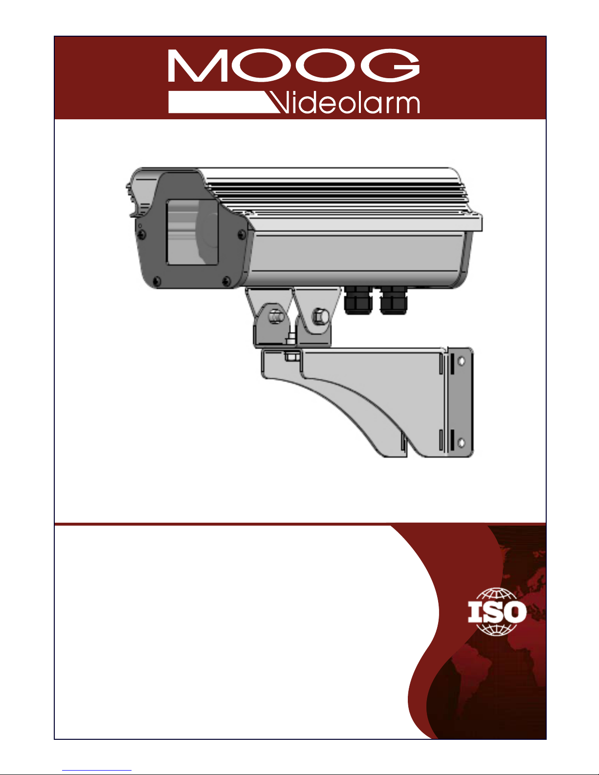
Remove the (2) screws on top of the
housing and lift it open.
• Quite (2) los tornillos encima de la cubierta y levántelos
abiertos.
• Enlevez (2) les vis sur le logement et soulevez-les ouvertes.
• Entfernen Sie die (2) Schrauben auf das Gehäuse und heben
Sie sie geöffnet an.
• Remova (2) os parafusos no alto da carcaça e levante-os
abertos.
• Rimuova (2) le viti in cima all'alloggiamento ed alzile aperte.
3
Place camera on sled and align mounting holes on
each. Adjust camera parallel to sled and tighten the
bolt on the bottom.
• Coloque la cámara fotográfica en el trineo y alinee los agujeros de
montaje en cada uno. Ajuste la cámara fotográfica paralela al trineo y
apriete el perno en el fondo.
• Placez l'appareil-photo sur le traîneau et alignez les trous de support sur
chacun. Ajustez l'appareil-photo parallèle au traîneau et serrez le
boulon sur le fond.
• Setzen Sie Kamera auf Schlitten und richten Sie Entlüftungslöcher auf
jedem aus. Justieren Sie die Kamera, die zum Schlitten parallel ist und
ziehen Sie den Schraubbolzen auf der Unterseite fest.
• Coloque a câmera no trenó e alinhe furos de montagem em cada um.
Ajuste a câmera paralela ao trenó e aperte o parafuso no fundo.
• Disponga la macchina fotografica sulla slitta ed allinei i fori di montaggio su ciascuno. Registri la macchina fotografica parallela alla slitta e
stringa il bullone sulla parte inferiore.
Sled
Screw
Camera Sled
4
5
6
Page 7

MM
2
AWG
,5 ,75 1,0 1,5 2,5 4 6
22 20 18 16 14 12 10
The beam angle may be adjusted on the
bottom of the unit.
• Éstos se recomiendan las distancias máximas para
24VAC con una gota del voltage del 10%.
• Ceux-ci sont recommandés des distances maximum
pour 24VAC avec une chute de tension de 10%.
• Diese werden maximale Abstände für 24VAC mit
einem 10% Spannungsabfall empfohlen.
• Estes são recomendados distâncias máximas para
24VAC com uma queda de tensão de 10%.
• Questi sono suggeriti distanze massime per 24VAC
con una differenza de potenziale di 10%.
12
These are recommended maximum distances
for 24VAC with a 10% voltage drop.
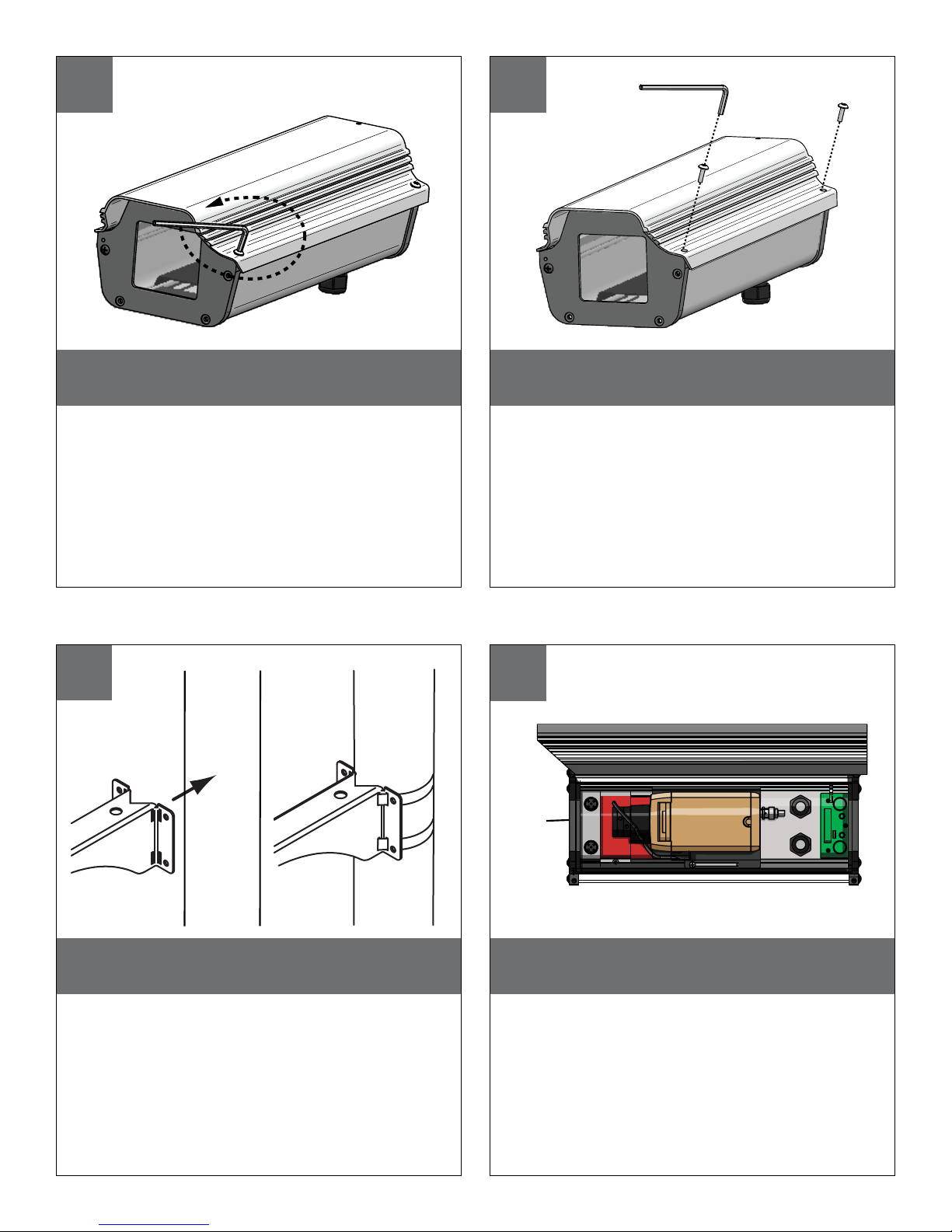
Run 24VAC power through a conduit plug, and place the
stripped power wire ends into the 24AC power board.
•
Funcione la energía 24VAC a través de un enchufe del conducto, y ponga los
extremos pelados del alambre de la energía en el tablero de energía 24AC.
• Courez la puissance 24VAC par une prise de conduit, et placez les extrémités
dépouillées de fil de puissance dans carte d'alimentation 24AC.
• Lassen Sie Energie 24VAC durch einen Rohrstecker, laufen und setzen Sie die
abgestreiften Energie Leitung Enden in das Energie 24AC Brett.
• Funcione o poder 24VAC através de um plugue da canalização, e coloque as
extremidades descascadas do fio do poder na placa de poder 24AC.
• Faccia funzionare l'alimentazione 24VAC tramite una spina del condotto e
disponga le estremità messe a nudo del legare di alimentazione nel bordo di
alimentazione 24AC.
INPUT
24Vac
7
Connection for wiring 24VAC network unit. Power consumption for heater, blower camera (max) 40VA.
Power output for camera 12VDC Maximum 1Amp (12 watts).
• Conexión para la unidad de la red del cableado 24VAC. Consumo de energía para el calentador, cámara fotográfica del soplador
(máximo) 40VA. Salida de energía para el 1Amp máximo de la cámara fotográfica 12VDC (12 vatios).
• Raccordement pour l'unité de réseau du câblage 24VAC. Puissance d'énergie pour le réchauffeur, appareil-photo de ventilateur
(maximum) 40VA. Rendement de puissance pour le 1Amp maximum de l'appareil-photo 12VDC (12 watts).
• Anschluß für Verdrahtung 24VAC Netzmaßeinheit. Leistungsaufnahme für Heizung, Gebläsekamera (Maximum) 40VA. Abgabeleistung
für Kamera 12VDC maximales 1Amp (12 Watt).
• Conexão para a unidade da rede da fiação 24VAC. Consumo de potência para o calefator, câmera do ventilador (máximo) 40VA.
Saída de poder para o 1Amp máximo da câmera 12VDC (12 watts).
• Collegamento per l'unità della rete dei collegamenti 24VAC. Assorbimento di corrente di energia per il riscaldatore, macchina
fotografica del ventilatore (massimo) 40VA. Uscita di alimentazione per il 1Amp massimo della macchina fotografica 12VDC (12 watt).
HEATER
24 VAC (IN)
BLOWER
- (Black)
BLOWER - (Red)
ACH13PCB
J1
THERM 2
THERM 1
(+)
(-)
YELLOW
PURPLE
12VDC
8
9
Page 8
Adjust the focus and focal length until the
desired field of view and focus is obtained.
• Ajuste el foco y la longitud focal hasta que el campo visual
deseado y el foco se obtiene.
• Ajustez le foyer et la longueur focale jusqu'à ce que le champ
visuel désiré et le foyer soit obtenu.
• Justieren Sie den Fokus und die fokale Länge, bis gewünscht
von der Ansicht auffangen und Fokus erhalten wird.
• Ajuste o foco e o comprimento focal até que o campo de
vista desejado e de foco esteja obtido.
• Registri il fuoco e la lunghezza focale fino ad ottenere il
campo voluto di visibilità ed il fuoco.
Adjust
Lens
Here
Close the top cover and tighten to the base with the
hex screws.
• Cierre la cubierta superior y apriete a la base con los tornillos
de la tuerca hexagonal.
• Fermez la couverture supérieure et serrez à la base avec les
vis de sortilège.
• Schließen Sie die obere Abdeckung und ziehen Sie zur
Unterseite mit den Hexagonschrauben fest.
• Feche a tampa superior e aperte-a à base com os parafusos
do hex.
• Chiuda la copertura superiore e stringa alla base con le viti
del hex.
If desired, use the security screws in place of hex
screws.
• Si está deseado, utilice los tornillos de la seguridad en lugar de
los tornillos de la tuerca hexagonal.
• Si désiré, utilisez les vis de sécurité au lieu des vis de sortilège.
• Wenn Sie gewünscht werden, benutzen Sie die Sicherheit
Schrauben anstatt der Hexagonschrauben.
• Se desejado, use os parafusos da segurança no lugar dos
parafusos do hex.
• Se voluto, utilizzi le viti di sicurezza al posto delle viti del hex.
If mounting to pole, attach assembly using 3/4” mounting straps (not provided).
• Si monta al poste, una a asamblea usando las correas que montan del
3/4"(no proporcionadas).
• Si montant au poteau, attachez l'assemblée en utilisant les courroies de
montage de 3/4"(non fournies).
• Bei der Befestigung zum Pfosten, bringen Sie Versammlung mit 3/4"den
Befestigungsbügeln an (nicht bereitgestellt).
• Se montando ao pólo, una o conjunto usando as cintas de montagem
de 3/4"(não fornecidas).
• Se montando al palo, fissi il complessivo usando le cinghie di montag-
gio di 3/4"(non fornite).
10
11
12
13
Page 9

Replacement Parts List
13
12
8
11
10
9
8
7
6
532
1
#
Part Number Description
1 RPACH010 Front Endcap Assembly
2 RPACH020 Lid Screws
3 H24ACH13 24V Heater
5 RPACH050 Camera Sled
6A
RPACH060 Top Extrusion
7 RPACH070 Bottom Extrusion
8 RPACHPK Packet Assembly
9 ACB2 24V Blower
10
11 RPACH110 Rear Endcap Assembly
12
WM800 Medium Duty W all Mount Bracket
13 RPACH130 Vent Hole Plugs
14
N/S RPTRANS03 24VAC to 12VDC AMP POWER SUPPLY
CAEH13
CDAH13
6B
Pcboard
Top Extrusion Wireless
RP71BCEH/HV
Page 10

Product Registration/Warranty
Thank you for choosing Videolarm. We value your patronage and are solely committed to
providing you with only the highest quality products available with unmatched customer service
levels that are second-to-none in the security industry.
Should a problem arise, rest assure that Videolarm stands behind its products
by offering some of the most impressive warranty plans available: 3 Years
on all Housings, Poles, Power Supplies, and Accessories and 5 Years on
all camera systems (SView, QView, Warriors), and InfraRed Illuminators.
Register Your Products
Option 1: Online Option 2: Mail-In
Take a few moments and validate your purchase with our Online Product Registration Form
at
www.videolarm.com/productregistration.jsp
or complete and mail-in the bottom portion of this flyer.
Register your recent Videolarm purchases and benefit from the following:
Simple and Trouble-Free RMA process•
Added into customer database to receive product updates / news•
Eliminate the need to archive original purchase documents: •
Receipts, Purchase Orders, etc…
Cut at the dotted Line
Place in envelope, affix stamp and mail to:
Main Contact Info
First Name: Last Name:
Professional Title: Company:
Address 1: Address 2:
City: State / Province/Country:
Zip / Postal Code: Phone Number: E-mail Address:
Please Circle One: Business Personal
Videolarm ATTN: Warranty
2525 Park Central Ave.
Decatur, GA 30035
Product Information
Name & Location of Company / Store where Purchased:
(City, State, Country)
Videolarm Product ID Product Description
Serial #
(Available only for Camera Systems, IR Illuminators, Wireless Devices)
PO#
 Loading...