

Page 1
For the mobile version of this guide, see:
animatics.com/docs/guides-html/c6_pnet/
Class 6 SmartMotor
Technology
Page 2

Copyright Notice
©2012-2019, Moog Inc., Animatics.
Moog Animatics Class 6 SmartMotor™ PROFINET Guide, Rev. D, PN: SC80100007-001.
This manual, as well as the software described in it, is furnished under license and may be
used or copied only in accordance with the terms of such license. The content of this manual is
furnished for informational use only, is subject to change without notice and should not be
construed as a commitment by Moog Inc., Animatics. Moog Inc., Animatics assumes no
responsibility or liability for any errors or inaccuracies that may appear herein.
Except as permitted by such license, no part of this publication may be reproduced, stored in a
retrieval system or transmitted, in any form or by any means, electronic, mechanical,
recording, or otherwise, without the prior written permission of Moog Inc., Animatics.
The programs and code samples in this manual are provided for example purposes only. It is
the user's responsibility to decide if a particular code sample or program applies to the
application being developed and to adjust the values to fit that application.
Moog Animatics and the Moog Animatics logo, SmartMotor and the SmartMotor logo,
Combitronic and the Combitronic logo are all trademarks of Moog Inc., Animatics. PROFINET
is a registered trademark of PROFIBUS Nutzerorganisation e.V. Other trademarks are the
property of their respective owners.
Please let us know if you find any errors or omissions in this manual so that we can improve it
for future readers. Such notifications should contain the words "PROFINET Guide" in the
subject line and be sent by e-mail to: animatics_marcom@moog.com. Thank you in advance
for your contribution.
Contact Us:
Americas - West
Moog Animatics
2581 Leghorn Street
Mountain View, CA 94043
USA
Tel: 1 650-960-4215 Tel: 1 610-328-4000 x3999
Support: 1 (888) 356-0357
Website: www.animatics.com
Email: animatics_sales@moog.com
Americas - East
Moog Animatics
750 West Sproul Road
Springfield, PA 19064
USA
Fax: 1 610-605-6216
Page 3

Table of Contents
Introduction 6
Purpose 7
PROFINET Overview 7
Equipment Required 9
Hardware 9
Software 9
Safety Information 10
Safety Symbols 10
Other Safety Considerations 10
Motor Sizing 10
Environmental Considerations 10
Machine Safety 11
Documentation and Training 12
Additional Equipment and Considerations 12
Safety Information Resources 12
Additional Documents 13
Related Guides 13
Other Documents 13
Additional Resources 14
PROFINET and PROFIBUS Resources 14
PROFINET Motor Pinouts, Connections and Status LEDs 15
PROFINET Motor Connectors and Pinouts 16
Cables and Diagram 17
Moog Animatics Industrial Ethernet Cables 17
M-style to M-style Ethernet Cable 17
M-style to RJ45 Ethernet Cable 17
Ethernet Cable Schematic 17
PROFINET Cable Diagram 18
Maximum Cable Length 18
PROFINET Status LEDs 19
PROFINET Configuration 20
Configure Motor with PC 21
User Program Requirements 21
Required Nonvolatile EEPROM Values 21
Moog Animatics Class 6 PROFINET Guide Rev. D
Page 3 of 76
Page 4

Configure PLC with PC 21
Configure SmartMotor to PROFINET 22
PLC Sends Commands to Motor 22
Network Data Format Example 22
PLCMemory 23
Sequence to Set Report Data to Motor Clock 24
PROFINET Communication Example 25
Sample Command Sequences 29
Overview 30
Command and Response Codes 30
Handshaking of Messages 30
Disabling Limits from Preventing Motion 30
Turning the Motor Shaft 30
Disable Limits and Clear Fault Status 31
Commands 31
PLCMemory 31
Disable positive limit, command EIGN(2) 31
Disable negative limit, command EIGN(3) 32
Clear fault status, command ZS 32
Initiate Mode Torque 33
Commands 33
PLCMemory 33
Set torque value, specify the response data 33
Initiate torque mode, command MT 33
Initiate Relative PositionMove 35
Commands 35
PLCMemory 35
Set acceleration value, command ADT=255 35
Set maximum velocity value, command VT=100000 35
Make a relative position move 36
User Program Commands 38
SNAME("string") 39
IPCTL(function,"string") 39
=ETH, RETH 39
ETHCTL(function, value) 42
Program Example 43
Moog Animatics Class 6 PROFINET Guide Rev. D
Page 4 of 76
Page 5

Output and Input Packets 44
Output and Input Packet Format 45
Command (Output) Packet Notes 50
Response (Input) Packet Notes 51
Alternate Communications Channel 52
Reserved Motor Variables 52
Command and Response Codes 53
Command Packet Codes to Motor Commands 54
Extended 16-bit command codes 61
Response Packet Codes to Motor Commands 64
Extended 16-bit response codes 69
Troubleshooting 72
Moog Animatics Class 6 PROFINET Guide Rev. D
Page 5 of 76
Page 6

Introduction
Introduction
This chapter provides information on the purpose and scope of this manual. It also provides
information on safety notation, related documents and additional resources.
Purpose 7
PROFINET Overview 7
Equipment Required 9
Hardware 9
Software 9
Safety Information 10
Safety Symbols 10
Other Safety Considerations 10
Motor Sizing 10
Environmental Considerations 10
Machine Safety 11
Documentation and Training 12
Additional Equipment and Considerations 12
Safety Information Resources 12
Additional Documents 13
Related Guides 13
Other Documents 13
Additional Resources 14
PROFINET and PROFIBUS Resources 14
Moog Animatics Class 6 PROFINET Guide Rev. D
Page 6 of 76
Page 7

Purpose
Purpose
This manual explains the Moog Animatics Class 6 SmartMotor™ support for the PROFINET®
protocol. It describes the major concepts that must be understood to integrate a SmartMotor
slave with a PLC or other PROFINET master. However, it does not cover all the low-level
details of the PROFINET protocol.
NOTE: The feature set described in this version of the manual refers to motor
firmware 6.0.2.25 or later.
This manual is intended for programmers or system developers who understand the use of
PROFINET. (The PROFINET v2.2 specifications are detailed in the following IECpublications:
IEC61158-6-10 Ed2.0, IEC61158-5-10 Ed2.0 and IEC61784-2 Ed2.0.) Therefore, this manual is
not a tutorial on those specifications or the PROFINET protocol. Instead, it should be used to
understand the specific implementation details for the Moog Animatics SmartMotor.
Additionally, examples are provided for the various modes of motion and accessing those
modes through PROFINET to operate the SmartMotor.
The Command and Response Code chapter of this manual includes details about the specific
commands available in the SmartMotor through the PROFINET protocol. The commands
include those required by the specification and those added by Moog Animatics. For details,
see Command and Response Codes on page 53. Also, see User Program Commands on page
38.
In addition to this manual, it is recommended that you visit the PROFINET/PROFIBUS website
(at http://www.profibus.com), where you will find documentation, tutorials, and other useful
resources.
PROFINET Overview
PROFINET is an independent, open fieldbus standard that allows different manufacturers of
automation products to communicate without special interface adjustments. Specifically,
PROFINET, which is optimized for high speed, is designed to communicate between control
systems and distributed I/O at the device level.
Moog Animatics has defined a set of 8-bit command and response codes to be transmitted and
received over PROFINET. For details, see Command Packet Codes to Motor Commands on
page 54. These codes generally correspond to Class 5 and Class 6 SmartMotor™ commands.
To set target position, for example, the "set target position" command code is transmitted
together with the data consisting of the target position value.
The PROFINET SmartMotor is a SmartMotor with the addition of the PROFINET connectors and
interface board, which then accepts commands as a slave over a PROFINET network. In
addition to communicating over PROFINET, SmartMotor commands may be sent through other
communication interfaces of the SmartMotor. Depending on the SmartMotor model, it may
also communicate over RS-232, RS-485 and/or USB.
The Moog Animatics communications profile over PROFINET is intended to integrate well with
a PLC that continuously transmits and receives cyclic data. The command and response codes
achieve this through a handshaking mechanism.
Certain configuration data is held in nonvolatile storage in the SmartMotor. Therefore, the
motor data EEPROM must be correctly initialized before PROFINET operation.
A PROFINET Generic Station Description (GSD) configuration file, which is an XML file (also
referred to as a "GSDML" file), is necessary for the host to configure the PROFINET master
Moog Animatics Class 6 PROFINET Guide Rev. D
Page 7 of 76
Page 8

PROFINET Overview
and to connect to the slave motor. Make sure you obtain the latest version of the file, which is
available from the Moog Animatics website Download Center. For more details, see Software
on page 9.
Document sections include Output and Input data formats (PROFINET cargo), a list of the
Moog Animatics PROFINET command codes explained in terms of the equivalent SmartMotor
commands, and a list of Moog Animatics PROFINET response codes explained in terms of the
equivalent SmartMotor commands.
Moog Animatics Class 6 PROFINET Guide Rev. D
Page 8 of 76
Page 9

Equipment Required
Equipment Required
The section describes the required PROFINET hardware and software.
Hardware
The following hardware is required:
l
Moog Animatics PROFINET SmartMotor™
l
Moog Animatics power supply or user-supplied equivalent
l
Moog Animatics RS-485 or USB communications cable that is compatible with the
SmartMotor
l
User-supplied PC with the Microsoft Windows operating system
l
User-supplied PLC with PROFINET master or other PROFINET master
l
Moog Animatics PROFINET cable, or equivalent, to connect the PLC to the SmartMotor's
industrial Ethernet port (for details, see PROFINET Motor Connectors and Pinouts on
page 16)
Software
The following software is required:
l
User-supplied PLC configuration software
l
Moog Animatics SMI software (latest version), which is available on the Moog Animatics
website at:
http://www.animatics.com/support/download-center.html
l
Moog Animatics PROFINET GSDML file, which is available on the Moog Animatics
website at:
http://www.animatics.com/support/download-center.html
NOTE: The PROFINET GSD configuration file name will have the form
"GSDML-Vx.x-MOOG ANIMATICS-SMC06DEV01-date.XML", where 'x.x' is the
version and 'date' is the release date. Make sure you obtain the latest version
of the file.
Moog Animatics Class 6 PROFINET Guide Rev. D
Page 9 of 76
Page 10
Safety Information
Safety Information
This section describes the safety symbols and other safety information.
Safety Symbols
The manual may use one or more of the following safety symbols:
WARNING: This symbol indicates a potentially nonlethal mechanical hazard,
where failure to follow the instructions could result in serious injury to the
operator or major damage to the equipment.
CAUTION: This symbol indicates a potentially minor hazard, where failure to
follow the instructions could result in slight injury to the operator or minor
damage to the equipment.
NOTE: Notes are used to emphasize non-safety concepts or related information.
Other Safety Considerations
The Moog Animatics SmartMotors are supplied as components that are intended for use in an
automated machine or system. As such, it is beyond the scope of this manual to attempt to
cover all the safety standards and considerations that are part of the overall machine/system
design and manufacturing safety. Therefore, the following information is intended to be used
only as a general guideline for the machine/system designer.
It is the responsibility of the machine/system designer to perform a thorough "Risk
Assessment" and to ensure that the machine/system and its safeguards comply with the
safety standards specified by the governing authority (for example, ISO, OSHA, UL, etc.) for
the locale where the machine is being installed and operated. For more details, see Machine
Safety on page 11.
Motor Sizing
It is the responsibility of the machine/system designer to select SmartMotors that are
properly sized for the specific application. Undersized motors may: perform poorly, cause
excessive downtime or cause unsafe operating conditions by not being able to handle the
loads placed on them. The System Best Practices document, which is available on the Moog
Animatics website, contains information and equations that can be used for selecting the
appropriate motor for the application.
Replacement motors must have the same specifications and firmware version used in the
approved and validated system. Specification changes or firmware upgrades require the
approval of the system designer and may require another Risk Assessment.
Environmental Considerations
It is the responsibility of the machine/system designer to evaluate the intended operating
environment for dust, high-humidity or presence of water (for example, a food-processing
environment that requires water or steam wash down of equipment), corrosives or chemicals
that may come in contact with the machine, etc. Moog Animatics manufactures specialized
Moog Animatics Class 6 PROFINET Guide Rev. D
Page 10 of 76
Page 11

Machine Safety
IP-rated motors for operating in extreme conditions. For details, see the Moog Animatics
Product Catalog, which is available on the Moog Animatics website.
Machine Safety
In order to protect personnel from any safety hazards in the machine or system, the
machine/system builder must perform a "Risk Assessment", which is often based on the ISO
13849 standard. The design/implementation of barriers, emergency stop (E-stop)
mechanisms and other safeguards will be driven by the Risk Assessment and the safety
standards specified by the governing authority (for example, ISO, OSHA, UL, etc.) for the
locale where the machine is being installed and operated. The methodology and details of
such an assessment are beyond the scope of this manual. However, there are various sources
of Risk Assessment information available in print and on the internet.
NOTE: The following list is an example of items that would be evaluated when
performing the Risk Assessment. Additional items may be required. The safeguards
must ensure the safety of all personnel who may come in contact with or be in the
vicinity of the machine.
In general, the machine/system safeguards must:
l
Provide a barrier to prevent unauthorized entry or access to the machine or system. The
barrier must be designed so that personnel cannot reach into any identified danger
zones.
l
Position the control panel so that it is outside the barrier area but located for an
unrestricted view of the moving mechanism. The control panel must include an E-stop
mechanism. Buttons that start the machine must be protected from accidental
activation.
l
Provide E-stop mechanisms located at the control panel and at other points around the
perimeter of the barrier that will stop all machine movement when tripped.
l
Provide appropriate sensors and interlocks on gates or other points of entry into the
protected zone that will stop all machine movement when tripped.
l
Ensure that if a portable control/programming device is supplied (for example, a handheld operator/programmer pendant), the device is equipped with an E-stop mechanism.
NOTE: A portable operation/programming device requires many additional
system design considerations and safeguards beyond those listed in this
section. For details, see the safety standards specified by the governing
authority (for example, ISO, OSHA, UL, etc.) for the locale where the
machine is being installed and operated.
l
Prevent contact with moving mechanisms (for example, arms, gears, belts, pulleys,
tooling, etc.).
l
Prevent contact with a part that is thrown from the machine tooling or other parthandling equipment.
l
Prevent contact with any electrical, hydraulic, pneumatic, thermal, chemical or other
hazards that may be present at the machine.
l
Prevent unauthorized access to wiring and power-supply cabinets, electrical boxes, etc.
Moog Animatics Class 6 PROFINET Guide Rev. D
Page 11 of 76
Page 12

Documentation and Training
l
Provide a proper control system, program logic and error checking to ensure the safety
of all personnel and equipment (for example, to prevent a run-away condition). The
control system must be designed so that it does not automatically restart the
machine/system after a power failure.
l
Prevent unauthorized access or changes to the control system or software.
Documentation and Training
It is the responsibility of the machine/system designer to provide documentation on safety,
operation, maintenance and programming, along with training for all machine operators,
maintenance technicians, programmers, and other personnel who may have access to the
machine. This documentation must include proper lockout/tagout procedures for maintenance
and programming operations.
It is the responsibility of the operating company to ensure that:
l
All operators, maintenance technicians, programmers and other personnel are tested
and qualified before acquiring access to the machine or system.
l
The above personnel perform their assigned functions in a responsible and safe manner
to comply with the procedures in the supplied documentation and the company safety
practices.
l
The equipment is maintained as described in the documentation and training supplied by
the machine/system designer.
Additional Equipment and Considerations
The Risk Assessment and the operating company's standard safety policies will dictate the
need for additional equipment. In general, it is the responsibility of the operating company to
ensure that:
l
Unauthorized access to the machine is prevented at all times.
l
The personnel are supplied with the proper equipment for the environment and their job
functions, which may include: safety glasses, hearing protection, safety footwear,
smocks or aprons, gloves, hard hats and other protective gear.
l
The work area is equipped with proper safety equipment such as first aid equipment,
fire suppression equipment, emergency eye wash and full-body wash stations, etc.
l
There are no modifications made to the machine or system without proper engineering
evaluation for design, safety, reliability, etc., and a Risk Assessment.
Safety Information Resources
Additional SmartMotor safety information can be found on the Moog Animatics website; open
the file "109_Controls, Warnings and Cautions.pdf" located at:
http://www.animatics.com/support/moog-animatics-catalog.html
OSHA standards information can be found at:
https://www.osha.gov/law-regs.html
ANSI-RIA robotic safety information can be found at:
http://www.robotics.org/robotic-content.cfm/Robotics/Safety-Compliance/id/23
Moog Animatics Class 6 PROFINET Guide Rev. D
Page 12 of 76
Page 13

Additional Documents
UL standards information can be found at:
http://ulstandards.ul.com/standards-catalog/
ISOstandards information can be found at:
http://www.iso.org/iso/home/standards.htm
EUstandards information can be found at:
http://ec.europa.eu/growth/single-market/european-standards/harmonisedstandards/index_en.htm
Additional Documents
The Moog Animatics website contains additional documents that are related to the information
in this manual. Please refer to the following list.
Related Guides
l
Class 6 SmartMotor™ Installation & Startup Guide
http://www.animatics.com/cl-6-install-startup-guide
l
Moog Animatics SmartMotor™ Developer's Guide
http://www.animatics.com/smartmotor-developers-guide
Other Documents
l
SmartMotor™ System Best Practices
http://www.animatics.com/system-best-practices-application-note
l
SmartMotor™ Product Certificate of Conformance
http://www.animatics.com/download/Declaration of Conformity.pdf
l
SmartMotor™ ULCertification
http://www.animatics.com/download/MA_UL_online_listing.pdf
l
SmartMotor Developer's Worksheet
(interactive tools to assist developer: Scale Factor Calculator, Status Words, CAN Port
Status, Serial Port Status, RMODE Decoder and Syntax Error Codes)
http://www.animatics.com/tools
l
Moog Animatics Product Catalog, which is available on the Moog Animatics website
http://www.animatics.com/support/moog-animatics-catalog.html
Moog Animatics Class 6 PROFINET Guide Rev. D
Page 13 of 76
Page 14

Additional Resources
Additional Resources
The Moog Animatics website contains useful resources such as product information,
documentation, product support and more. Please refer to the following addresses:
l
General company information:
http://www.animatics.com
l
Product information:
http://www.animatics.com/products.html
l
Product support (Downloads, How To videos, Forums, Knowledge Base, and FAQs):
http://www.animatics.com/support.html
l
Sales and distributor information:
http://www.animatics.com/sales-offices.html
l
Application ideas (including videos and sample programs):
http://www.animatics.com/applications.html
PROFINET and PROFIBUS Resources
PROFINET and PROFIBUS are common standard maintained by PROFIBUS and PROFINET
International (PI):
l PROFIBUS and PROFINET International (PI) website:
http://www.profibus.com/
Moog Animatics Class 6 PROFINET Guide Rev. D
Page 14 of 76
Page 15

PROFINET Motor Pinouts, Connections and Status LEDs
PROFINET Motor Pinouts,
Connections and Status LEDs
The following sections describe the motor pinouts, system connections and the status LEDs.
PROFINET Motor Connectors and Pinouts 16
Cables and Diagram 17
Moog Animatics Industrial Ethernet Cables 17
M-style to M-style Ethernet Cable 17
M-style to RJ45 Ethernet Cable 17
Ethernet Cable Schematic 17
PROFINET Cable Diagram 18
Maximum Cable Length 18
PROFINET Status LEDs 19
Moog Animatics Class 6 PROFINET Guide Rev. D
Page 15 of 76
Page 16
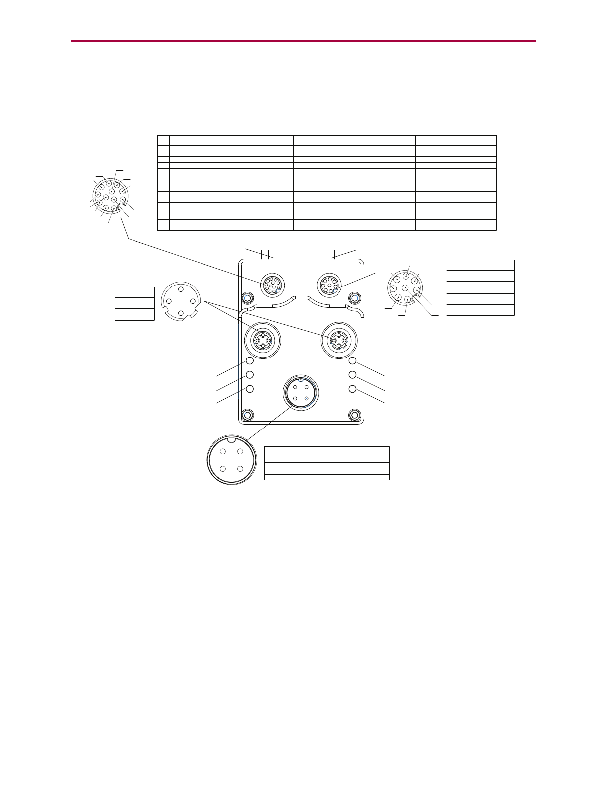
PROFINET Motor Connectors and Pinouts
1
2 3
4
POWER INPUT
PIN
FUNCTION
DESCRIPTION
1
24 VDC
CONTROL I/O POWER
2
EARTH
CHASSIS GROUND
3
GND
MOTOR COMMON GROUND
4
48 VDC
MOTOR POWER
COMMUNICATION
PIN
FUNCTION
1
GND-COMMON
2
RS-485B CH0
3
RS-485A CH0
4
ENC A+ (IN/OUT)
5
ENC B- (IN/OUT)
6
ENC A- (IN/OUT)
7
5 VDC OUT
8
ENC B+
(IN/OUT)
1
2
3
4
5
6
7
8
1
2
3
4
5
6
7
8
9
10
11
12
I/Os
PIN
FUNCTION
DEFAULT
1
IN0
GENERAL PURPOSE
2
IN1
GENERAL PURPOSE
3
IN2/POSLIMIT
POSITIVE LIMIT
4
IN3/NEGLIMIT
NEGATIVE LIMIT
5
IN/OUT4
GENERAL PURPOSE
6
IN
/OUT
5
GENERAL PURPOSE
7
IN6
GENERAL PURPOSE
8
IN7-DRVEN
DRIVE ENABLE
9
OUT8/BRAKE
BRAKE OUTPUT
10
OUT9-NOFAULT
NOT FAULT
11
24 VDC OUT*
CONTROL I/O POWER
12
GND
MOTOR COMMON GROUND
INPUT OR OUTPUT
INPUT, DISCRETE OR ANALOG
POSSIBLE (SELECTABLE) FUNCTIONS
INPUT, DISCRETE OR ANALOG
INPUT
INPUT
INPUT/OUTPUT
INPUT/OUTPUT
INPUT
INPUT
OUTPUT
OUTPUT
POWER OUTPUT**
N/A
GENERAL PURPOSE
GENERAL PURPOSE
POSITIVE LIMIT OR GENERAL PURPOSE
NEGATIVE LIMIT OR GENERAL PURPOSE
GENERAL PURPOSE, OR EXTERNAL ENCODER
INDEX CAPTURE
GENERAL PURPOSE, OR INTERNAL ENCODER
INDEX CAPTURE
GENERAL PURPOSE, G COMMAND, OR
HOMING INPUT (ETHERCAT ONLY)
N/A
NOT FAULT
BRAKE OUTPUT OR GENERAL-PURPOSE OUTPUT
DRIVE ENABLE
*NOTE: 2 AMPS MAX **SUPPLIED FROM POWER INPUT PIN 1
CONTROL I/O POWER
RS-485 serial communication uses a
voltage differential signal. Appropriate
terminating resistors should be included
on the RS-485 network to ensure reliable
performance. For details, see the section
Power and RS-485 Com Multidrop.
1
2
3
4
Shield tied to motor
housing
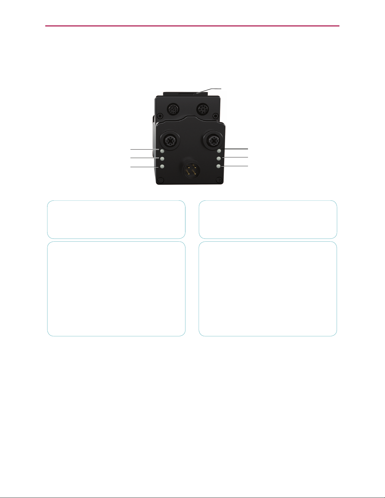
LED 4: PROFINET Link 1 Port LED
LED 2: PROFINET System Fail LED
LED 0: Motor Drive LED
LED 5: PROFINET Link 2 Port LED
LED 3: PROFINET Bus Fail LED
LED 1: Motor Busy LED
USB Port LED
SD Card LED
PIN
FUNCTION
1
+TD
2
+RD
3
-TD
4
-RD
PROFINET
PROFINET Motor Connectors and Pinouts
The following figure provides an overview of the PROFINET connectors and pinouts available
on the Class 6 SmartMotors.
Moog Animatics Class 6 PROFINET Guide Rev. D
Page 16 of 76
Page 17
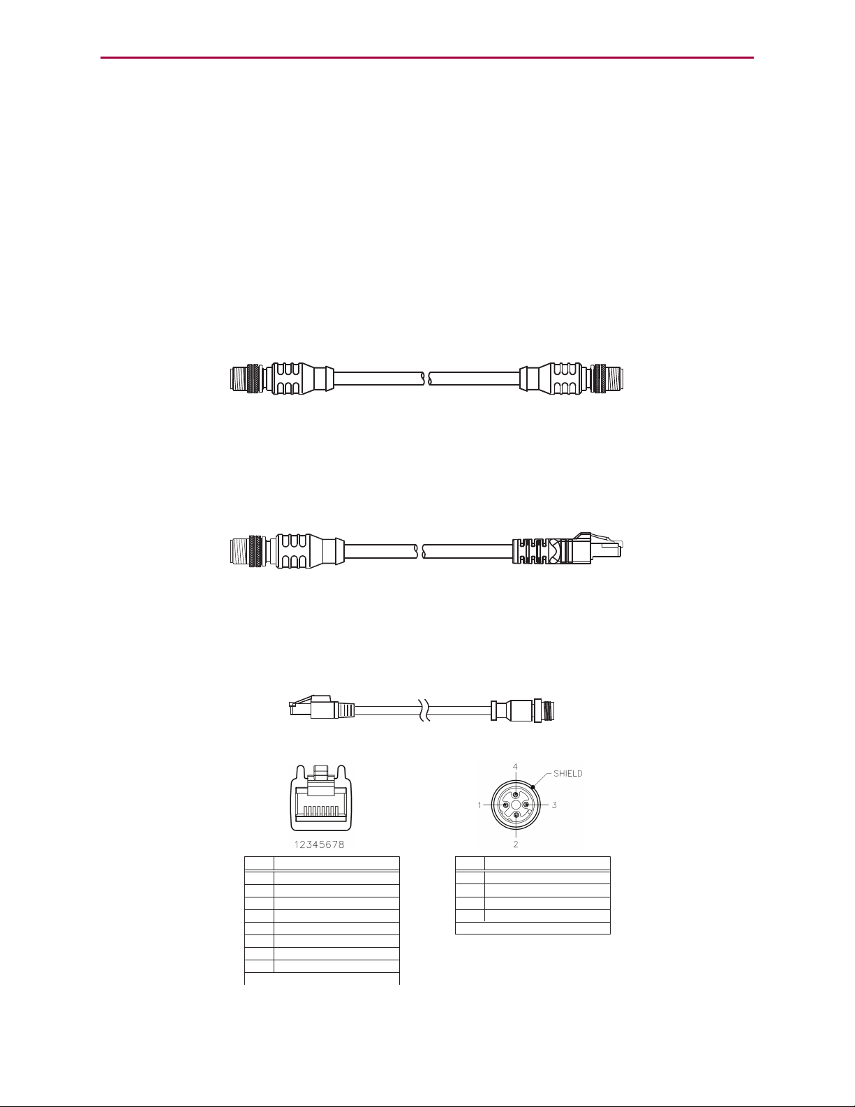
Cables and Diagram
Industrial Ethernet Connector
(Motor end of cable)
PIN
1
2
3
4
+TX
+RX
-TX
-RX
DESCRIPTION
Shield tied to motor housing
RJ45 Connector
(EtherCAT master end of cable)
1
2
3
4
5
6
7
8
+TX
-TX
+RX
No Connection
No Connection
-RX
No Connection
No Connection
PIN
DESCRIPTION
Shield tied to RJ45 connector
Cables and Diagram
This section provides information on Moog Animatics industrial Ethernet cables and a
PROFINET system cable diagram.
Moog Animatics Industrial Ethernet Cables
The following cables are available from Moog Animatics.
M-style to M-style Ethernet Cable
This cable has M12 male threaded connectors at both ends. It is available in 1, 3, 5 and 10
meter lengths. For the standard cable, use part number CBLIP-ETH-MM-xM, where "x"
denotes the cable length. A right-angle version is also available; use part number
CBLIP-ETH-MM-xMRA.
M-style to RJ45 Ethernet Cable
This cable has an M12 male threaded connector at one end, and an RJ45 male connector at the
opposite end. It is available in 1, 3, 5 and 10 meter lengths. For the standard cable, use part
number CBLIP-ETH-MR-xM, where "x" denotes the cable length. A right-angle version is also
available; use part number CBLIP-ETH-MR-xMRA.
Ethernet Cable Schematic
The following figure provides details for creating a custom industrial Ethernet shielded cable.
NOTE: The motor end of the cable requires an industrial Ethernet connector.
Moog Animatics Class 6 PROFINET Guide Rev. D
Page 17 of 76
Page 18
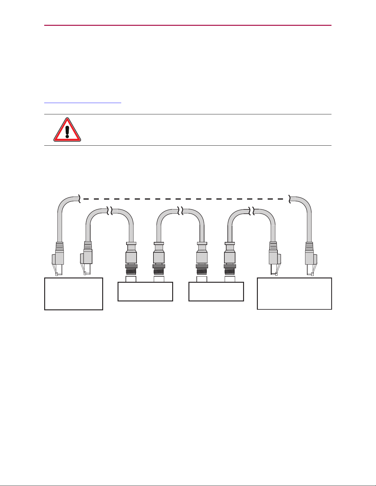
PROFINET Cable Diagram
PROFINET Bus
Other PROFINET device:
- I/O block,
- Servo drive,
- etc.
PROFINET Master
- PC,
- PLC,
- etc.
Moog Animatics
SmartMotor
Moog Animatics
SmartMotor
Optional ring for cable redundancy*
*Ring conguration requires specic PROFINET modes and supporting devices
PROFINET Cable Diagram
PROFINET can support line, tree or star device-connection topology. The supported network
topology and maximum number of devices depends on the selected PROFINET mode and
network class. For example, higher performing modes, like PROFINET IRT, require
specialized equipment. For PROFINET network design and installation details, see the
information available at:
http://www.profinet.com
CAUTION: To minimize the possibility of electromagnetic interference (EMI),
all connections should use shielded Ethernet Category 5 (Cat 5), or better,
cables.
The following diagram shows an example PROFINET network with the SmartMotors daisy
chained to the master device. An optional "ring" configuration can be created if it is supported
by the selected PROFINET mode and network devices.
Maximum Cable Length
For transmission speeds of 100 Megabits/second on shielded Ethernet Cat 5 cable, EtherCAT
and PROFINET allow cable lengths up to 100 meters between network nodes.
NOTE: Unlike other fieldbus protocols, PROFINET does not require terminators at
each end of the network bus.
Moog Animatics Class 6 PROFINET Guide Rev. D
Page 18 of 76
Page 19
PROFINET Status LEDs
Off No power
Solid green Drive on
Blinking green Drive off, no faults
Triple red flash Watchdog fault
Solid red Faulted or no drive enable input
Off Not busy
Solid green Drive on, trajectory in progress
Flashing # red Flashes fault code* (see below)
when Drive LED is solid red
Refer to the corresponding SmartMotor
fieldbus guide
Refer to the corresponding SmartMotor
fieldbus guide
Refer to the corresponding SmartMotor
fieldbus guide
Refer to the corresponding SmartMotor
fieldbus guide
Under cover:
USB Active LED
SD Card LED (for SD
Card-equipped motors)
LED 4: PROFINET Link 1 Input LED
LED 2: PROFINET System Fail LED
LED 0: Motor Drive LED
LED 5: PROFINET Link 2 Output LED
LED 3: PROFINET Bus Fail LED
LED 1: Motor Busy LED
LED 0: Motor Drive LED LED 1: Motor Busy LED
LED 3: (Network specific) LED
LED 5: Link LED
LED 2: (Network specific) LED
LED 4: Link LED
LED Status on Power-up:
• With no program and the travel limit inputs are low:
LED 0 solid red; motor is in fault state due to travel limit fault
LED 1 off
• With no program and the travel limits are high:
LED 0 solid red for 500 milliseconds then flashing green
LED 1 off
• With a program that only disables travel limits:
LED 0 red for 500 milliseconds then flashing green
LED 1 off
Flash
1
2
3
4
5
6
7
8
9
10
11
Description
NOT Used
Bus Voltage
Over Current
Excessive Temperature
Excessive Position
Velocity Limit
dE/Dt - First derivative of position error is excessive
Hardware Positive Limit Reached
Hardware Negative Limit Reached
Software Positive Travel Limit Reached
Software Negative Travel Limit Reached
LED 1 Fault Codes:
*Busy LED pauses for 2 seconds before flashing the code
Flickering = On/Off in 0.1 sec; Blinking = On/Off in 0.5 sec; Flashing = separated by 1 sec for PROFINET LEDs and 2 sec for Fault Codes
Flashing green Active
Flashing red Suspended
Solid red USB power detected, no
configuration
USB Active LED
Blinking green Busy, do not remove card
Solid green
Card detected
Solid red
Card with no SmartMotor data
SD Card LED (for SD Card-equipped motors)
No card, bad or damaged cardO
PROFINET Status LEDs
This following figure and tables describe the functionality of the PROFINET Status LEDs on the
SmartMotor.
Moog Animatics Class 6 PROFINET Guide Rev. D
Page 19 of 76
Page 20

PROFINET Configuration
PROFINET Configuration
The following sections describe how to configure your SmartMotor to communicate over
PROFINET.
Configure Motor with PC 21
User Program Requirements 21
Required Nonvolatile EEPROM Values 21
Configure PLC with PC 21
Configure SmartMotor to PROFINET 22
PLC Sends Commands to Motor 22
Network Data Format Example 22
PLCMemory 23
Sequence to Set Report Data to Motor Clock 24
PROFINET Communication Example 25
Moog Animatics Class 6 PROFINET Guide Rev. D
Page 20 of 76
Page 21

Configure Motor with PC
Configure Motor with PC
Use the following procedure to configure the SmartMotor for communication with the PC.
Refer to the figures in PROFINET Communication Example on page 25.
1.
Connect the SmartMotor to the power supply.
2.
If the motor is already configured, you may skip the balance of this procedure.
3.
Connect the motor to the PC.
4.
Launch the SmartMotor™ Interface (SMI) software, version 2.4.3.6 or later.
User Program Requirements
No user program is specifically required by the Class 6 PROFINET SmartMotor.
Required Nonvolatile EEPROM Values
The nonvolatile settings can be entered using the SMI software’s Terminal window. For details
on using the Terminal window, see the SMI software online help.
After the configuration settings have been entered, cycle the SmartMotor’s power for the new
configuration to take effect.
To change the nonvolatile station name for PROFINET within a user program, see the following
code example:
...
SNAME("mymotor1")
a=ETH(0)
IF(a&2)
Z 'Execute reset if Station Name changed
ENDIF
...
Configure PLC with PC
Use the following procedure to configure the PLC for communication with the PC. Refer to the
figures in PROFINET Communication Example on page 25.
NOTE: You may skip this section if the PLC is already configured.
1.
Using the PLC configuration software running in a PC, load the SmartMotor’s GSDML
(XML) file, set it up as a PROFINET device from the catalog, and define the correct
Station Name. For more details on the GSDML file, seeSoftware on page 9.
2.
Determine the location of the PLC memory to exchange three words (six bytes) of
PROFINET output to the motor and the seven words (fourteen bytes) of input from the
SmartMotor. The GSDML file defines the three output words and seven input words, but
it does not specify where this is located in the PLC memory. That location is determined
by the configuration tools supplied by the PLC manufacturer.
Moog Animatics Class 6 PROFINET Guide Rev. D
Page 21 of 76
Page 22
Configure SmartMotor to PROFINET
Configure SmartMotor to PROFINET
Use the following procedure to configure the SmartMotor to PROFINET. Refer to the PROFINET
Status LEDs on page 19.
1.
Verify the corresponding Link LED is ON (green) with possible occasional flashing, which
indicates there is communication traffic.
2.
After connecting the motor, the System Fail LED should go from solid red to flashing
red, which indicates it is waiting for an I/O controller.
3.
After the I/O controller makes a connection, the System Fail LED turns off.
PLC Sends Commands to Motor
Program the PLC or modify by hand the PLC memory areas, as described below, to send the
desired commands over PROFINET and communicate with the motor.
The following are sequences of commands sent, which show all the intermediary PROFINET
packet output data states.
NOTE: Bold characters indicate changes in the PLC memory output buffer and input
buffer values.
Network Data Format Example
Each byte below is represented as two hexadecimal characters. For example, 7A represents
hex 7A or decimal 122.
COMMAND FROM
I/O CONTROLLER
Cmd
Code
00 7A 0000 0000 .......... 00 00 0000 0000 0680 0000 0000 0000
Resp
Code
Data
Cmd
Code
Ack
Resp
Code
Ack
Resp
Data
The following are the SmartMotor’s Status Word response bit definitions (the response shown
above is 0680).
RESPONSE FROM
SMART MOTOR
Status
Word
Measured
Position
Pos
Error
Moog Animatics Class 6 PROFINET Guide Rev. D
Page 22 of 76
Page 23

PLCMemory
Bit Description
0 Busy Trajectory
1 Historical + limit (hardware and software limit)
2 Historical - limit (hardware and software limit)
3 Index report available for the rising edge of internal encoder
4 Position wraparound occurred
5 Position error fault
6 Temperature limit fault
7 Drive off
8 Index input active
9 + limit active (hardware and software limit)
10 - limit active (hardware and software limit)
11 Communication error of any type
12 Network user bit, defined by ETHCTL(12,x) command, see User Program
Commands on page 38
13 Command error (includes math and array errors)
14 Peak overcurrent occurred
15 Drive ready
PLCMemory
Each byte below is represented as two hexadecimal characters. For example, 0680 represents
hex 680 or decimal 134.
Output to slave motor: Input from slave motor:
3 two-byte words out 7 two-byte words in
0000 0000 0000 0000 0000 0000 0086 0000 0000 0000
A status word of 0x0680 (which breaks down to the bits 0000 0110 1000 0000) indicates the
servo is off, the left and right limits have been activated, and the drive is not ready.
Moog Animatics Class 6 PROFINET Guide Rev. D
Page 23 of 76
Page 24

Sequence to Set Report Data to Motor Clock
Sequence to Set Report Data to Motor Clock
Command
Code
Insert response code 0x7A in the output buffer, which is being transmitted continuously (i.e.,
cyclically) by the master to the slave motor. See Command Packet Codes to Motor Commands
on page 54 to find response code RCLK and its value, hex 7A.
007A 0000 0000 0000 0000 0000 0680 0000 0000 0000
Wait for response code acknowledge in the input buffer, which is being received continuously
(i.e., cyclically) by the master as a response from the slave motor. The clock data begins
being cyclic updates.
007A 0000 0000 007A 0000 03A1 0680 0000 0000 0000
As time goes on, the clock data is updated.
007A 0000 0000 007A 0001 B01A 0680 0000 0000 0000
Response
Code
0x7A RCLK
Data
Command
Motor
Moog Animatics Class 6 PROFINET Guide Rev. D
Page 24 of 76
Page 25

PROFINET Communication Example
PROFINET Communication Example
The following example illustrates PROFINET communications. It sends commands from a PLC
over PROFINET to cause the SmartMotor to continually report its changing clock value to the
PLC. The value is displayed by the PLC registers containing the PROFINET data received from
the motor. It changes as the updated clock value is received.
To create a PROFINET connection to the SmartMotor:
1.
Install the SMI software. For more details, see the Moog Animatics Class 6
SmartMotor™ Installation & Startup Guide.
2.
Connect control power to the 12-pin connector.
a.
Pin 11 is 24 Volt control power.
b.
Pin 12 is Ground or 24 Volt low.
3.
Connect a USBcable from the PC to the USB connector on the SmartMotor. Refer to the
following figure.
USBConnection from PCto SmartMotor
Moog Animatics Class 6 PROFINET Guide Rev. D
Page 25 of 76
Page 26

PROFINET Communication Example
4.
In the SMI software Configuration window, right-click the USB category and select
Detect Motors on USB from the menu.
When detection has completed, Motor 1 will be shown under the USB network.
5.
Double click Motor1 to open the Motor View tool. Click Poll to update the Status.
Moog Animatics Class 6 PROFINET Guide Rev. D
Page 26 of 76
Page 27

PROFINET Communication Example
6.
Select the Network tab and then Poll again. Note the default PROFINET name.
7.
Set the station name. Refer to the Terminal window in the following figure.
a.
Execute RETH(0) to get the current Ethernet interface status bit (352 decimal =
160 hex).
b.
Type SNAME("mymotor1") into the Terminal window.
Use the following PROFINET name conventions:
l Characters a-z (lowercase only, uppercase is not permitted)
l Numbers 0-9, but cannot start with a number
l No underscores or other special characters; the hyphen and period are per-
mitted, but not as the first or last character
l No more than 127 characters total or 63 characters as a name component
within the device name (e.g., a character string between two periods); may
be further limited by your configuration software
l Cannot be formatted as an IP address (dotted-decimal notation)
l Cannot begin with the characters "port-nnn-", where "nnn" are three
numeric characters 0-9 (e.g., port-735-)
c.
Execute RETH(0) to get the updated Ethernet interface status bit (354 decimal =
162 hex). After the station name has changed, the status for the report from
RETH(0) should indicate a PROFINET status configuration change on Bit 1 (zero
based). Refer to User Program Commands on page 38.
NOTE: The new station name in the following figure (in the red box)
won't be shown until power is cycled and the motor is redetected. Refer
to the next step.
Moog Animatics Class 6 PROFINET Guide Rev. D
Page 27 of 76
Page 28

PROFINET Communication Example
Entering and Verifying the Station Name
8. Cycle motor power to use the new configuration and station name. Refer to the red box
in the previous figure.
9.
Configure your PLC through its serial port using a PC that is running your PLC
configuration software.
a.
Load the motor’s PROFINET GSDML file.
b.
Assign and display the PLC registers associated with the motor’s PROFINET input
and output data.
10.
Connect the PROFINET cable to the PLC and the SmartMotor.
11.
Power cycle the SmartMotor to initialize it with the configured values.
12.
Enter the PROFINET motor response code to report the motor clock in the PLC PROFINET
data registers (i.e., in the "3 words out", the second byte is the motor response code).
a. Using a PC that is running your PLC software, and with your PLC online, enter the
PROFINET response code 122 decimal, x7A hex into the "response code" field.
b.
Watch the clock value being updated in your PLC PROFINET input registers "7
words in", bytes 2-5.
For examples of sending command sequences and communication handshaking, refer to
Sample Command Sequences on page 29.
Moog Animatics Class 6 PROFINET Guide Rev. D
Page 28 of 76
Page 29

Sample Command Sequences
Sample Command Sequences
This chapter contains sample PROFINET command sequences.
Overview 30
Command and Response Codes 30
Handshaking of Messages 30
Disabling Limits from Preventing Motion 30
Turning the Motor Shaft 30
Disable Limits and Clear Fault Status 31
Commands 31
PLCMemory 31
Disable positive limit, command EIGN(2) 31
Disable negative limit, command EIGN(3) 32
Clear fault status, command ZS 32
Initiate Mode Torque 33
Commands 33
PLCMemory 33
Set torque value, specify the response data 33
Initiate torque mode, command MT 33
Initiate Relative PositionMove 35
Commands 35
PLCMemory 35
Set acceleration value, command ADT=255 35
Set maximum velocity value, command VT=100000 35
Make a relative position move 36
Moog Animatics Class 6 PROFINET Guide Rev. D
Page 29 of 76
Page 30

Overview
Overview
These sequences illustrate:
l
Disabling limits from preventing motion
l
Turning the shaft in torque mode
l
Moving a relative distance
l
Command and response codes
l
Handshaking of messages
Command and Response Codes
The command and response codes are described in Command Packet Codes to Motor
Commands on page 54 The symbolic command and response codes are listed, along with their
values and the related SmartMotor™ command. See Output and Input Packets on page 44 for
further explanation of how to use the command and response codes.
Handshaking of Messages
Handshaking of output message changes is included in the protocol to ensure coherence in the
packet. See Output and Input Packets on page 44 for an explanation of handshaking.
Disabling Limits from Preventing Motion
At power up, if limit switches are not connected to the motor, the electrical state of the limit
pins will default to indicate that the motor is at the limits. This will prevent motion unless the
limits are disabled and any limit faults are cleared.
These commands may be included in the user program that is downloaded to the motor and
runs at power up. If the user program does not include these commands or the limits are not
held inactive at power-up, before attempting to turn the motor shaft, you must perform the
command sequence described in Disable Limits and Clear Fault Status on page 31.
Turning the Motor Shaft
After disabling the limits and clearing any faults, the shaft may be turned using the following
command sequences:
l
Initiate Mode Torque on page 33
l
Initiate Relative PositionMove on page 35
These sequences are described in following sections.
Moog Animatics Class 6 PROFINET Guide Rev. D
Page 30 of 76
Page 31

Disable Limits and Clear Fault Status
Disable Limits and Clear Fault Status
Commands
Command
Code
Response
Code
Data
Resulting
SmartMotor
Command
0x01 0x30 EIGN(2)
0x01 0x33 EIGN(3)
0x01 0x44 ZS
PLCMemory
Output to slave motor: Input from slave motor:
3 words out 7 words in
0000 0000 0000 0000 0000 0000 0680 0000 0000 0000
Cmd
Code
00 7A 0000 0000 .......... 00 00 0000 0000 0680 0000 0000 0000
Resp
Code
Data
Cmd
Code
Ack
Resp
Code
Ack
Resp
Data
Status
Word
Measured
Position
Disable positive limit, command EIGN(2)
Insert command EIGN(2) data = 0x30 in the output buffer, which is being transmitted
continuously (i.e., cyclically) by the master to the slave motor.
Pos
Error
0000 0000 0030 0000 0000 0000 0680 0000 0000 0000
Set command code 0x01 in the output buffer.
0100 0000 0030 0000 0000 0000 0680 0000 0000 0000
Wait for a command code acknowledge in the input buffer, which is being received
continuously (i.e., cyclically) by the master as a response from the slave motor.
0100 0000 0030 0100 0000 0000 0480 0000 0000 0000
The command code acknowledges the motor has received the command.
Clear the command code in the output buffer (handshake) to prepare for the next command.
0000 0000 0030 0100 0000 0000 0480 0000 0000 0000
Wait for acknowledgment of the cleared command code.
0000 0000 0030 0000 0000 0000 0480 0000 0000 0000
Moog Animatics Class 6 PROFINET Guide Rev. D
Page 31 of 76
Page 32

Disable negative limit, command EIGN(3)
Disable negative limit, command EIGN(3)
Insert command EIGN(3) data = 0x33 in the output buffer, which is being transmitted
continuously (i.e., cyclically) by the master to the slave motor.
0000 0000 0033 0000 0000 0000 0480 0000 0000 0000
Set command code 0x01in the output buffer.
0100 0000 0033 0000 0000 0000 0480 0000 0000 0000
Wait for command code acknowledge in the input buffer, which is being received continuously
(i.e., cyclically) by the master as a response from the slave motor.
0100 0000 0033 0100 0000 0000 0080 0000 0000 0000
The command code acknowledges the motor has received the command.
Clear the command code in the output buffer (handshake) to prepare for the next command:
0000 0000 0033 0100 0000 0000 0080 0000 0000 0000
Wait for acknowledgment of the cleared command code.
0000 0000 0033 0000 0000 0000 0080 0000 0000 0000
Clear fault status, command ZS
Insert command ZS data = 0x44 in output buffer, which is being transmitted continuously
(i.e., cyclically) by the master to the slave motor.
0000 0000 0044 0000 0000 0000 0086 0000 0000 0000
Set command code 0x01in the output buffer.
0100 0000 0044 0000 0000 0000 0086 0000 0000 0000
Wait for command code acknowledge in the input buffer, which is being received continuously
(i.e., cyclically) by the master as a response from the slave motor. Fault status is reported
cleared to 0x0080.
0100 0000 0044 0100 0000 0000 0080 0000 0000 0000
The command code acknowledges the motor has received the command.
Clear command code in output buffer (handshake) to prepare for the next command.
0000 0000 0044 0100 0000 0000 0080 0000 0000 0000
Wait for acknowledgment of the cleared command code.
0000 0000 0044 0000 0000 0000 0080 0000 0000 0000
Moog Animatics Class 6 PROFINET Guide Rev. D
Page 32 of 76
Page 33

Initiate Mode Torque
Initiate Mode Torque
Commands
Command
Code
0x94 0xA2 3072 (0x0c00) T=3072
0x01 0xA2 0x21 MT
0x01 0x0C G (begin motion)
Response
Code
Data
RVA (polled motor response)
RVA (polled motor response)
Resulting
SmartMotor
Command
PLCMemory
Output to slave motor: Input from slave motor:
3 words out 7 words in
0000 0000 0000 0000 0000 0000 0080 0000 0000 0000
Set torque value, specify the response data
This will command T=3072 and specify the response data to be the current velocity.
Begin to set torque T=3072 by putting x 00 00 0C 00 in output data.
0000 0000 0C00 0000 0000 0000 0080 0000 0000 0000
Insert command code 0x94 and response code 0xA2.
94A2 0000 0C00 0000 0000 0000 0080 0000 0000 0000
Wait for acknowledge in input buffer:
94A2 0000 0C00 94A2 0000 0000 0080 0000 0000 0000
Now, T=3072 (0x0c00), and the response data value will be velocity. Clear the command code
output buffer (handshake) to prepare for the next command.
00A2 0000 0C00 94A2 0000 0000 0080 0000 0000 0000
Wait for acknowledgment of command code clear in input buffer.
00A2 0000 0C00 00A2 0000 0000 0080 0000 0000 0000
Initiate torque mode, command MT
Insert command 0x21 data to begin torque mode.
00A2 0000 0021 00A2 0000 0000 0080 0000 0000 0000
Moog Animatics Class 6 PROFINET Guide Rev. D
Page 33 of 76
Page 34

Initiate torque mode, command MT
Insert command code 0x01.
01A2 0000 0021 00A2 0000 0000 0080 0000 0000 0000
Wait for command code 1 acknowledgment.
01A2 0000 0021 01A2 0000 0000 0080 0000 0000 0000
Insert command code 0x00.
00A2 0000 0021 01A2 0000 0000 0080 0000 0000 0000
Wait for command code 0 acknowledgment.
00A2 0000 0021 00A2 0000 0000 0080 0000 0000 0000
Insert command 0x0C data to initiate open-loop motion.
00A2 0000 000C 00A2 0000 0000 0080 0000 0000 0000
Insert command code 0x01.
01A2 0000 000C 00A2 0000 0000 0080 0000 0000 0000
When the command is received by the motor, the motor shaft will begin turning if it is not in a
fault state.
Wait for command code acknowledgment in the input buffer.
01A2 0000 000C 01A2 0000 0000 0080 0000 0000 0000
Velocity becomes nonzero, and it is reported as 0x00 14 00 00 in this example. Status
changes are reported as 0x0009 in this example. Position becomes nonzero, and it is reported
as 0x00 00 00 A2 in this example.
01A2 0000 000C 01A2 0014 0000 0009 0000 00A2 0000
Insert command code 0x00 to clear the command code output buffer (handshake) to prepare
for the next command. The position is continually updated. Velocity is a filtered value
measured in:
encoder counts per sample period x 65,536
00A2 0000 000C 01A2 0014 0000 0009 0000 02EE 0000
Wait for the command code clear acknowledge in the input buffer.
00A2 0000 0000 00A2 0014 0000 0009 0000 05DC 0000
Set data to 0.
0000 0000 0000 00A2 0014 0000 0009 0000 05DC 0000
Moog Animatics Class 6 PROFINET Guide Rev. D
Page 34 of 76
Page 35

Initiate Relative PositionMove
Initiate Relative PositionMove
Commands
Command
Code
0x64 255 (0xff) ADT=255
0xA3 100000 VT=100000
0x01 0x1D Change to Mode Position (MP)
0x03 10000 PRT=10000 G
Response
Code
0xA2 RVA (polled motor response)
Data
Resulting
SmartMotor
Command
PLCMemory
Output to slave motor: Input from slave motor:
3 words out 7 words in
0000 0000 0000 0000 0000 0000 0080 0000 0000 0000
Set acceleration value, command ADT=255
Begin to set ADT=255 by putting x00 00 00 FF in output data.
0000 0000 00FF 0000 0000 0000 0080 0000 0000 0000
Insert command code 0x64 and response code 0xA2.
64A2 0000 00FF 0000 0000 0000 0080 0000 0000 0000
Wait for acknowledge in input buffer.
64A2 0000 00FF 64A2 0000 0000 0080 0000 0000 0000
Now, ADT=255, and the response data value will be velocity. Clear the command code output
buffer (handshake) to prepare for the next command.
00A2 0000 00FF 64A2 0000 0000 0080 0000 0000 0000
Wait for acknowledge of command code clear in input buffer.
00A2 0000 00FF 00A2 0000 0000 0080 0000 0000 0000
Set maximum velocity value, command VT=100000
Insert code commanded velocity of VT=100000 = 0x0001 86A0.
00A2 0001 86A0 00A2 0000 0000 0080 0000 0000 0000
Moog Animatics Class 6 PROFINET Guide Rev. D
Page 35 of 76
Page 36

Make a relative position move
Insert command code 0xA3 to set VT=100000.
A3A2 0001 86A0 00A2 0000 0000 0080 0000 0000 0000
Wait for command code acknowledge in the input buffer.
A3A2 0001 86A0 A3A2 0000 0000 0080 0000 0000 0000
Insert command code 0x00.
00A2 0001 86A0 A3A2 0000 0000 0080 0000 0000 0000
Wait for command code acknowledge in the input buffer.
00A2 0001 86A0 00A2 0000 0000 0080 0000 0000 0000
Insert data 0x0000 001D for MP when command is 1.
00A2 0000 001D 00A2 0000 0000 0080 0000 0000 0000
Insert command code 0x01.
01A2 0001 86A0 00A2 0000 0000 0080 0000 0000 0000
Wait for command code acknowledge in the input buffer.
01A2 0001 86A0 01A2 0000 0000 0080 0000 0000 0000
Insert command code 0x00.
00A2 0001 86A0 01A2 0000 0000 0080 0000 0000 0000
Make a relative position move
Insert data for a relative move of 10,000 counts = 0x0000 2710.
00A2 0000 2710 00A2 0000 0000 0080 0000 0000 0000
Insert command code value 0x03.
03A2 0000 2710 00A2 0000 0000 0080 0000 0000 0000
Wait for command code acknowledge in the input buffer.
03A2 0000 2710 03A2 0000 0000 0080 0000 0000 0000
The motor performs its move. While the trajectory is in the slew phase, you will see
something like:
03A2 0000 2710 03A2 0001 86AD 0009 0000 CA23 0011
Moog Animatics Class 6 PROFINET Guide Rev. D
Page 36 of 76
Page 37

which is the following input data:
command code acknowledge 03
response code acknowledge A2
response data current 0001 86AD
velocity (100,000 in slew)
status 0009
Bt = 1
Bi = 1
measured current position 0000 CA23
measured current position error 0011
Make a relative position move
Moog Animatics Class 6 PROFINET Guide Rev. D
Page 37 of 76
Page 38

User Program Commands
User Program Commands
The SmartMotor's EEPROM can store nonvolatile PROFINET information about the network.
For proper PROFINET operation, each SmartMotor must have a unique station name set with
the SNAME instruction. This is can be accomplished: at the PLC over PROFINET; with SMI and
a USB connection over channel 8, or RS-485 on channel 0; with a SmartMotor user program.
NOTE: Nonvolatile memory will be read at power-up or after the Z (reset)
command has been executed.
The following sections list the commands used to operate the motor on a PROFINET network.
SNAME("string") 39
IPCTL(function,"string") 39
=ETH, RETH 39
ETHCTL(function, value) 42
Program Example 43
Moog Animatics Class 6 PROFINET Guide Rev. D
Page 38 of 76
Page 39

SNAME("string")
SNAME("string")
Set PROFINET Station Name
The SNAMEcommand is used to set a unique PROFINET station name. The setting is
nonvolatile. It can use up to 54 characters; the factory default is smc6dev01. It will set the
configuration change bit (Bit 1) returned by the ETH/RETH command (see below) if the Station
Name has changed from the previous value in EEPROM.
Use the following PROFINET name conventions:
l Characters a-z (lowercase only, uppercase is not permitted)
l Numbers 0-9, but cannot start with a number
l No underscores or other special characters; the hyphen and period are permitted, but
not as the first or last character
l No more than 127 characters total or 63 characters as a name component within the
device name (e.g., a character string between two periods); may be further limited by
your configuration software
l Cannot be formatted as an IP address (dotted-decimal notation)
l Cannot begin with the characters "port-nnn-", where "nnn" are three numeric characters
0-9 (e.g., port-735-)
IPCTL(function,"string")
Sets IP address, Mask, or Gateway
The IPCTLcommand is used to set the IPaddress, subnet mask or gateway. The setting is
nonvolatile. This command is not usually needed. Typically, the PLC will handle these settings
during PROFINET network initialization.
The possible function values are:
0: set IP address
1: set Mask
2: set Gateway
The "string" is formatted as an IP address, e.g., IPCTL(0,"192.168.0.10"). By default, these
values are set to 0 (i.e., "0.0.0.0").
=ETH, RETH
Get PROFINET error
The =ETH and RETH commands are used to assign/report errors and certain status
information for the PROFINET bus.
l
Assigned to a program variable: x=ETH(y)
l
As a report: RETH(y)
Refer to the following table for details.
Moog Animatics Class 6 PROFINET Guide Rev. D
Page 39 of 76
Page 40

=ETH, RETH
Assignment Report Description
=ETH(0) RETH(0) Gets the PROFINET status bits:
0 Initialization incomplete
Read specific error code from ETH(54);
Contact Moog Animatics
(Confirm SNAME setting if encountering a problem)
1 Configuration change
2 Reserved
3 Network processor failure
Likely due to excessive control power supply noise or ESD
event
4 Reserved
5 Reserved
6 I/O Controller is STOP
7 I/O Controller is RUN
8 I/O Controller aborted cyclic communications
9 Network commanded configuration change
=ETH(5) RETH(5) LFW firmware version as 32-bit integer; e.g., 3.1.0.1 would be a
value 50397185 (0x03010001).
=ETH(6) RETH(6) The current Network Lost program label number. For details, see
ETHCTL(function, value) on page 42.
=ETH(7) RETH(7) Processor type:
-1 Failed
0 Unknown
1 netX 10
2 netX 50
3 netX 51/52
4 netX 100
=ETH(8) RETH(8) Protocol type after successful initialization (Confirm SNAME set-
ting if encountering a problem) See also RETH(19)
0 Not defined
1 PROFINET
2 EtherCAT
3 EtherNet/IP
=ETH(9) RETH(9) The current value assigned to the Network Lost action. For
details, see ETHCTL(function, value) on page 42.
RETH(15) IP address; value is in dotted-decimal format; report only.
RETH(16) Subnet mask; value is in dotted-decimal format; report only.
RETH(17) Gateway; value is in dotted-decimal format; report only.
RETH(18) MAC ID string formatted; report only; e.g., 00:01:02:a9:ff:00
Moog Animatics Class 6 PROFINET Guide Rev. D
Page 40 of 76
Page 41

=ETH, RETH
Assignment Report Description
=ETH(19) RETH(19)
Report the detected LFW ProtocolClass. This gives a wider range
of values than the known and supported protocols listed in ETH
(8). Values designated according to NXF/LFW file loaded into
network processor and too numerous to list here. These are the
values for the supported protocols: (introduced in firmware
6.0.2.41 or later)
0 Not Defined
21 PROFINET
9 EtherCAT
10 Ethernet/IP
... ...
=ETH(30) RETH(30) Gets the present receive I/O data size in bytes
=ETH(31) RETH(31) Gets the present transmit I/O data size in bytes
=ETH(45) RETH(45) IP address as integer; e.g., for an IP address of 192.168.1.3 (C0
A8 01 03 hex), this command reports -1062731517 (it reports as a
32-bit signed value).
=ETH(46) RETH(46) IP subnet mask as integer; e.g., for an IP netmask of 255.255.0.0
(FF FF 00 00 hex), this command reports -65536 (it reports as a
32-bit signed value).
=ETH(47) RETH(47) IP gateway as integer; e.g., for an IP gateway of 192.168.1.1 (C0
A8 01 01 hex), this command reports -1062731519 (it reports as a
32-bit signed value).
=ETH(48) RETH(48) Low 3 bytes of MAC ID (device ID) as integer; e.g., for a MACID
of 00:01:02:a9:ff:00, this command reports 11140864 (00 a9 ff
00 hex).
=ETH(49) RETH(49) High 3 bytes of MAC ID (device ID) as integer; e.g., for a MACID
of 00:01:02:a9:ff:00, this command reports 258 (00 00 01 02
hex).
=ETH(50) RETH(50) Gets the last internal error code
=ETH(51) RETH(51) Gets the last internal error code source
=ETH(54) RETH(54) Gets the Initialization error code; for further information, read
this error when RETH(0) bits 0 or 1 are indicated, or when RETH
(8) returns 0.
The value -1070596029 indicates an invalid SNAMEformat was
used.
=ETH(57) RETH(57) Gets the real-time Ethernet sync correction
=ETH(58) RETH(58) Gets the real-time Ethernet sync count
Moog Animatics Class 6 PROFINET Guide Rev. D
Page 41 of 76
Page 42

ETHCTL(function, value)
ETHCTL(function, value)
Control network features
Commands execute based on the function argument, which controls Ethernet functions. After
issuing an ETHCTL command the Ethernet error codes will be checked to determine the state
of Status Word 2, bit 6 (Ethernet error).
Command Description
ETHCTL(1,TBD)
...
ETHCTL(5,TBD)
ETHCTL(6,<value>)
ETHCTL(7,TBD) Reserved for future use.
ETHCTL(8,TBD) Reserved for future use.
ETHCTL(9,<value>) PROFINET Network Lost Action. This setting is nonvolatile.
Reserved for future use.
User program label number. This setting is nonvolatile.
Program label to jump to if the NET_LOST_LABEL option is chosen
from the NET_LOST_ACTION function.
This function has no effect if the NET_LOST_ACTION is anything other
than NET_LOST_LABEL.
0 Ignore, no action (default setting)
1 Send OFF command to motor
2 Send X command to motor (soft stop)
3 Send S command to motor (immediate stop)
Send GOSUB(x) command, where x is the value of the user
4
program label.
Send GOTO(x) command, where x is the value of the user pro-
5
gram label.
NOTE: Loss of network is an edge-triggered event if I/O Control goes
from RUN to any other state.
ETHCTL(10,x) Allows the position field of 14 byte (7 word) input module to be recon-
figured for alternate data from the motor. See 240, xF0 on page 60.
ETHCTL(11,TBD) Reserved for future use.
ETHCTL(12,<value>) Network user bit set or clear. This is a bit in the status word of the 14
byte (7 word) input module. Also visible in response code 164 "legacy
status word":
0 Clear Bit 12 of SmartMotor I/O Network Bit
1 Set Bit 12 of SmartMotor I/O Network Bit
ETHCTL(45,x) Set IP address as integer; e.g., to set for an IP address of
192.168.1.3 (C0 A8 01 03 hex), x=3232235779; non-volatile.
ETHCTL(46,x) Set IP subnet mask as integer; e.g., to set for an IP netmask of
255.255.0.0 (FF FF 00 00 hex), x=4294901760; non-volatile.
Moog Animatics Class 6 PROFINET Guide Rev. D
Page 42 of 76
Page 43

Program Example
Command Description
ETHCTL(47,x) Set IP gateway as integer; e.g., to set for an IP gateway of
192.168.1.1 (C0 A8 01 01 hex), x=3232235777; non-volatile.
ETHCTL(50,<value>) Resets the internal error register: RETH(50); the value argument is
ignored.
ETHCTL(51,<value>) Resets the internal error register: RETH(51); the value argument is
ignored.
ETHCTL(58,<value>) Clears the real-time Ethernet sync count
Program Example
The following code example sets the nonvolatile station name.
SNAME("mymotor1")
a=ETH(0)
IF( a&2 )
Z 'Execute reset if station name changed
ENDIF
'Add rest of program below
Moog Animatics Class 6 PROFINET Guide Rev. D
Page 43 of 76
Page 44

Output and Input Packets
Output and Input Packets
This section describes the PROFINET Output and Input packet format. It also provides notes
for the Command (Output) packets and Response (Input) Packets.
Output and Input Packet Format 45
Command (Output) Packet Notes 50
Response (Input) Packet Notes 51
Moog Animatics Class 6 PROFINET Guide Rev. D
Page 44 of 76
Page 45

Output and Input Packet Format
Output and Input Packet Format
Two options exist for the input/output packet size:
l 3 words (6 bytes) out, 7 words (14 bytes)in
l 12 words (24 bytes) out, 28 words (56 bytes) in
This option is only available with firmware 6.0.2.41 or later, and requires XML (GSDML)
date -20190118 or later. The I/O controller (PLC) will have an interface for loading the
XML file and choosing these options for the input and output packets. Some tools may
provide a drag-and-drop interface for selecting the available modules from the XML file
and placing them into the 2 available slots in the motor.
NOTE: Only the two combinations of specific in/out sizes are allowed. For example,
3 words out cannot be used with 28 words in.
Output (3 Words) Data Format (I/O Controller Command)
Offset
Description Notes
Word Byte
0 0 Command Code
1 Response Code
1 2 Command Data Value (32 bits), big-endian format
3
2 4
5
Input (7 words) Data Format (Motor response)
Offset
Description Notes
Word Byte
0 0 Command Code Acknowledge
1 Response Code Acknowledge
1 2 Response Data Value (32 bits), big-endian format
3
2 4
5
3 6 Status Word (16 bits), big-endian format
7
Affected by
byte / word
swap
parameter
N/A
N/A
Yes
Affected by
byte / word
swap
parameter
N/A
N/A
Yes
Yes
Moog Animatics Class 6 PROFINET Guide Rev. D
Page 45 of 76
Page 46

Output and Input Packet Format
Offset
Description Notes
Word Byte
4 8 Measured Position (32 bits), big-endian format
9
5 10
11
6 12 Position Error (16 bits), big-endian format
13
Command Code: Indicates a command to be issued to the SmartMotor. Also, see Command
Data Value.
Response Code: Indicates additional data to be included in the Response Data Value of the
Input Data.
Command Data Value: Indicates the 32-bit value to be used in conjunction with the
Command Code.
Command Code Acknowledge: Returned in the Input Data to indicate that a Command
Code was processed.
Response Code Acknowledge: Returned in the Input Data to indicate that a Response Code
was processed and that the current Response Data Value corresponds to that Response Code.
NOTE:This field can be configured to report al[0] or af
[0].
Affected by
byte / word
swap
parameter
Yes
Yes
Response Data Value: 32-bit value returned in the Input Data in response to a Response
Code.
Status Word: SmartMotor's current status word (16 bit).
Measured Position: SmartMotor's current measured position value (32-bit); result of RPA
command.
Position Error: SmartMotor’s current commanded trajectory position less the current
measured position.
Extended format: 12 words (24 bytes) out, 28 words (56 bytes) in. This format was created
for the purpose of easier access to reading data cyclically from the motor. Up to 8 response
data items can be read on every cycle, though the first reponse item is required for certain
special items, see notes.
There is still only 1 command code item because most commands require a sequence of
events to operate correctly, and multiple fields could cause conflict.
The command and response codes have been extended to 16-bit values in this extended
format. This allows for a wider set of codes and direct access to variables. See Extended 16bit command codes on page 61, and Extended 16-bit response codes on page 69.
Several pre-set fields have been removed from the extended format: position, status word,
position error. These are still available in the list of response codes (codes 141, 164, 143
respectively), and can be selected by setting those response request codes in the output data.
Position error is a full 32-bit when accessed by this method.
NOTE: The PROFINET SmartMotor supports the byte/word swap parameter as of
firmware 6.0.2.41 or later
Output (12 Words) Data Format (I/O Controller Command)
Moog Animatics Class 6 PROFINET Guide Rev. D
Page 46 of 76
Page 47

Output and Input Packet Format
Offset
Description Notes
Word Byte
0 0 Reserved (write as 0x00)
1 Reserved (write as 0x00)
1 2 Command Data Value (32 bits)
3
2 4
5
3 6 Command code request (16 bits) Yes
7
4 8 Response code 0 request (16 bits)
9
5 10 Response code 1 request (16 bits) 2 Yes
11
6 12 Response code 2 request (16 bits) 2 Yes
13
7 14
15
See note 1: some codes must use of this section
Response code 3 request (16 bits) 2 Yes
4 N/A
4 N/A
1 Yes
Affected by
byte / word
parameter
Yes
swap
8 16 Response code 4 request (16 bits) 2 Yes
17
9 18 Response code 5 request (16 bits) 2 Yes
19
10 20 Response code 6 request (16 bits) 2 Yes
21
11 22 Response code 7 request (16 bits) 2 Yes
23
Input (28 words) Data Format (Motor response)
Offset
Description Notes
Word Byte
0 0 Reserved (reports as 0xFF)
1 Reserved (reports as 0xFF)
1 2 Reserved (ignore, reports as 0)
3
Reserved (ignore, reports as 0) N/A
3 N/A
3 N/A
Affected by
byte / word
N/A
swap
parameter
Moog Animatics Class 6 PROFINET Guide Rev. D
Page 47 of 76
Page 48

Output and Input Packet Format
Offset
Description Notes
Word Byte
2 4
5
3 6
7
4 8
9
5 10
11
6 12
13
7 14 Response code 3 ack (16 bits) 2 Yes
15
8 16 Response code 4 ack (16 bits) 2 Yes
17
Reserved (ignore, reports as 0) N/A
Reserved (ignore, reports as 0) N/A
Command code ack (16 bits) Yes
Response code 0 ack (16 bits)
See note 1: some codes must use of this section
Response code 1 ack (16 bits) 2 Yes
Response code 2 ack (16 bits) 2 Yes
1 Yes
Affected by
byte / word
parameter
swap
9 18 Response code 5 ack (16 bits) 2 Yes
19
10 20 Response code 6 ack (16 bits) 2 Yes
21
11 22 Response code 7 ack (16 bits) 2 Yes
23
12 24 Response data 0 (32 bits)
25
13 26
27
14 28 Response data 1 (32 bits) Yes
29
15 30
31
16 32 Response data 2 (32 bits) Yes
33
17 34
See note 1: some codes must use of this section
Yes
35
Moog Animatics Class 6 PROFINET Guide Rev. D
Page 48 of 76
Page 49

Output and Input Packet Format
Offset
Description Notes
Word Byte
18 36 Response data 3 (32 bits) Yes
37
19 38
39
20 40 Response data 4 (32 bits) Yes
41
21 42
43
22 44 Response data 5 (32 bits) Yes
45
23 46
47
24 48 Response data 6 (32 bits) Yes
49
Affected by
byte / word
parameter
swap
25 50
51
26 52 Response data 7 (32 bits) Yes
53
27 54
55
NOTE: 1) This response request code location is allowed to include attributes
(request codes) 214-225 (special access to variables and EEPROM). It is
recommended to reserve this slot for this type of access. For constantly read
information, like access to variables (using response codes above 255), position,
etc., use response code locations 1-7 instead.
NOTE: 2) This response request code location is not allowed to use attributes
(request codes) 214-225, an error code (255) will result. These request code
locations 1-7 are recommended for information that must be read every cycle, like
a variable, position, velocity, current, etc.
NOTE: 3) These fields report 255 as protection so that the data will be interpreted
as an error if PLC program / controller reads this and attempts to interpret as 14byte input format. It is also helpful for the PLC program / controller to read this
when the 56 byte input mode is intended because it will provide confirmation by
reporting 255. A PLC program could use this as a verification check.
NOTE: 4) You must write 0 to these fields. If any other value is written, then the
remainder of the output packet will be ignored. This is for protection in case the
PLC/Controller is attempting to write in the 6 byte output format but has the 24byte format configured.
Moog Animatics Class 6 PROFINET Guide Rev. D
Page 49 of 76
Page 50

Command (Output) Packet Notes
Command (Output) Packet Notes
The following are notes regarding the Command (Output)Packets:
l
A command is issued to the SmartMotor exactly one time after the Command Code or
Command Data Value changes in the output data. To issue a command:
a.
Set the Command Code to 0.
b.
Wait for Command Code Acknowledge = 0.
c.
Set the Command Data Value to the desired value.
d.
Set the Command Code to the desired command.
e.
Wait for Command Code Acknowledge = Command Code.
l
For <value>, insert the Command Data Value.
l
For the variables <a to zzz>:
l
<a to z> u8VarIndexSet (0-25)
l
<aa to zz> u8VarIndexSet (26-51)
l
<aaa to zzz> u8VarIndexSet (52-77)
l
For <index>, insert the array index stored in u8ArrIndexSetActual.
l
For <length>, insert the length stored in u8VarLenSet or u8ArrLenSet.
l
Curly brackets {} indicate binary data rather than ASCII characters.
l
The PROFINET interface does not interfere with the SmartMotor's EPTR command for
access to EEPROM. Therefore, the user program may use the EPTR command at the
same time.
Moog Animatics Class 6 PROFINET Guide Rev. D
Page 50 of 76
Page 51

Response (Input) Packet Notes
Response (Input) Packet Notes
The following are notes regarding the Command (Output)Packets:
l
The requests associated with any Response Codes other than 214-225 are issued to the
SmartMotor continuously (or according to the polling rate if set). When the Response
Code in the output data transitions to a value in the range of 214-225, the associated
request will be issued to the SmartMotor exactly one time after transition to one of
those values. To issue a request for data:
a.
Set the Response Code to 0.
b.
Wait for Response Code Acknowledge = 0.
c.
Set the Response Code to the desired value.
d.
Wait for Response Code Acknowledge = Response Code read data from Response
Data Value.
e.
Repeat as desired if not Response Codes 214-225.
l For <value>, insert the Response Data Value.
l
For the variables <a to zzz>:
l <a to z> u8VarIndexGet (0-25)
l <aa to zz> u8VarIndexGet (26-51)
l <aaa to zzz> u8VarIndexGet (52-77)
l
For <index>, insert the array index stored in u8ArrIndexGetActual.
l
For <length>, insert the length stored in u8VarLenGet or u8ArrIndexGet.
l
Curly brackets {} indicate binary data rather than ASCII characters.
l
The Response Data Value for a GET_MODE (SmartMotor RMODE) command will contain
the integer code returned by the SmartMotor, which may be unexpected by users
familiar with the RMODE command in older Moog Animatics products. For details on the
RMODE command, see the Moog Animatics SmartMotor™ Command Reference Guide.
l
The PROFINET interface does not use the SmartMotor's EPTR command during
initialization to read startup parameters from the SmartMotor. Therefore, the user
program may use EPTR command at the same time. Also, the SmartMotor variable zzz
is not used by the PROFINET interface, which may be unexpected by users familiar with
older Moog Animatics products.
Moog Animatics Class 6 PROFINET Guide Rev. D
Page 51 of 76
Page 52

Alternate Communications Channel
Alternate Communications Channel
In addition to communicating over PROFINET, commands in the SmartMotor™ programming
language may be sent through an existing communications channel of the SmartMotor. For
details, see the Moog Animatics SmartMotor™ User's Guide.
Reserved Motor Variables
The PROFINET interface does not:
l
Require the reservation of any user variables. Some older Moog Animatics products
required the reservation of yyy and zzz. However, this is not the case in the PROFINET
interface—these variables are freely available for the user.
l
Require the reservation of any serial channels. Therefore, all other ports and associated
channels are freely available to the user for the application.
l
Interfere with the EPTR variable of the EEPROM command set. When PROFINET
accesses the EEPROM, it is done through a private version of EPTR. Therefore, the user
no longer has to monitor variable zzz for shared access. The user may access the
EEPROM at any time.
NOTE: EEPROM reads may still cause a user command to wait until the
EEPROM is available, but there is no user interaction required.
Moog Animatics Class 6 PROFINET Guide Rev. D
Page 52 of 76
Page 53

Command and Response Codes
Command and Response Codes
This section lists the PROFINET packet command and response codes and their corresponding
SmartMotor commands.
Command Packet Codes to Motor Commands 54
Extended 16-bit command codes 61
Response Packet Codes to Motor Commands 64
Extended 16-bit response codes 69
Moog Animatics Class 6 PROFINET Guide Rev. D
Page 53 of 76
Page 54

Command Packet Codes to Motor Commands
Command Packet Codes to Motor Commands
This section provides a reference table of PROFINET command packet codes and
corresponding SmartMotor commands.
Variables beginning with u8, u16 or u32 are internal to the motor’s PROFINET module.
For the variables:
l <a to z> use values (0 to 25)
l <aa to zz> use values (26 to 51)
l <aaa to zzz> use values (52 to 77)
Command
Code
decimal,
hex
0, x00 N/A
1, x01 0, x00
1, x01 1, x01
1, x01 2, x02
1, x01 3, x03
1, x01 4, x04
1, x01 5, x05
1, x01 6, x06
1, x01 7, x07
1, x01 8, x08
1, x01 9, x09
1, x01 10, x0A
1, x01 11, x0B
1, x01 12, x0C
1, x01 13, x0D
1, x01 14, x0E
1, x01 15-18,
1, x01 19, x13
1, x01 20-22,
1, x01 23, x17
1, x01 24, x18
1, x01 25-27,
1, x01 28, x1C
1, x01 29, x1D
1, x01 30, x1E
Command
Data
Value
decimal,
x80F-x12
x14-x16
x19-x1B
hex
Event
for
update
N/A
C/D*
C/D*
C/D*
N/A
C/D*
C/D*
C/D*
N/A
C/D*
C/D*
C/D*
C/D*
C/D*
N/A
N/A
N/A
N/A
N/A
N/A
C/D*
N/A
C/D*
C/D*
N/A
Command Description
NULL / NOP - No command requested
Does not perform any action, this command code
provided as a way to not initiate a new command,
or as a value to alternate to prior to setting a new
command.
Engage brake BRKENG
Use only internal brake; disable external brake EOBK(-1)
Direct brake to output number 8 EOBK(8)
(Reserved)
Release brake BRKRLS
Brake while servo inactive BRKSRV
Brake while trajectory inactive BRKTRJ
(Reserved)
Select internal encoder for servo ENC0
Select exter nal encoder for servo ENC1
End user program END
Transfer buffered PID tuning to live values F
Start motion (GO) G
(Obsolete) Use KG=0 KGOFF
(Obsolete) Use KG=<value>, command 131 KGON
(Obsolete)
(Reserved) not implemented
(Obsolete)
(Reserved) not implemented
Set mode follow and zero out MF0
(Obsolete)
Initiate mode follow quadrature MFR
Enable position mode MP
(Obsolete)
Smart
Motor
Command(s)
Moog Animatics Class 6 PROFINET Guide Rev. D
Page 54 of 76
Page 55

Command Packet Codes to Motor Commands
Command
Code
decimal,
hex
1, x01 31, x1F
1, x01 32, x20
1, x01 33, x21
1, x01 34, x22
1, x01 35, x23
1, x01 36, x24
1, x01 37, x25
1, x01 38-40,
1, x01 41, x29
1, x01 42, x2A
1, x01 43, x2B
1, x01 44, x2C
1, x01 45, x2D
1, x01 46, x2E
1, x01 47, x2F
1, x01 48, x30
1, x01 49, x31
1, x01 50, x32
1, x01 51, x33
1, x01 52, x34
1, x01 53, x35
1, x01 54, x36
1, x01 55, x37
1, x01 56, x38
1, x01 57, x39
1, x01 58, x3A
1, x01 59, x3B
1, x01 60, x3C
1, x01 61, x3D
1, x01 62, x3E
1, x01 63, x3F
1, x01 64, x40
1, x01 65, x41
1, x01 66, x42
1, x01 67, x43
Command
Data
Value
decimal,
x26-x28
hex
Event
for
update
C/D*
C/D*
C/D*
C/D*
C/D*
C/D*
C/D*
N/A
C/D*
C/D*
C/D*
C/D*
N/A
C/D*
N/A
C/D*
N/A
C/D*
C/D*
N/A
C/D*
C/D*
C/D*
C/D*
C/D*
C/D*
C/D*
C/D*
C/D*
C/D*
C/D*
C/D*
C/D*
C/D* Not available in Class 6 PROFINET
C/D*
Configure step and direction, and zero out MS0
Initiate mode step ratio calculation MSR
Enable torque mode MT
Immediately engage MTB brake MTB
Enable velocity mode MV
Stop servoing the motor OFF
Divide PID sample rate by 1 PID1
(Reserved)
Execute s tored program RUN
End program if RUN has not been commanded
yet (since power up)
Abruptly stop move in progress S
Make I/O 0 an input EIGN(0)
(Obsolete) Use CMD_OUT(x)
Make I/O 1 an input EIGN(1)
(Obsolete) Use CMD_OUT(x)
Make I/O 2 an input; dis able right-limit function EIGN(2)
(Obsolete) Use CMD_OUT(x)
Set I/O C to be a right-limit input EILP
Make I/O 3 an input; dis able left-limit function EIGN(3)
(Obsolete) Use CMD_OUT(x)
Set I/O 3 to be a left-limit input EILN
Slow motor motion to stop X
Total system reset Z
Reset overcurrent error bit Za
Reset serial data parity violation latch bit, i.e.,
clears the parity error bits in RCHN(0) and RCHN
(1)
Reset communications buffer overflow latch bit,
i.e., clears the overflow error bits in RCHN(0) and
RCHN(1)
Not available in Class 6 PROFINET
Reset position error fault Ze
Reset serial communication framing error latch
bit, i.e., clears the framing error bits in RCHN(0)
and RCHN(1)
Reset overtemperature fault; requires
temperature to fall 5 degrees below limit
Reset historical left-limit latch bit Zl
Reset historical right-limit latch bit Zr
Reset command scan error latch bit Zs
Reset encoder wr aparound event latch bit Zw
Command Description
Smart
Motor
Command(s)
RUN?
Zh
Moog Animatics Class 6 PROFINET Guide Rev. D
Page 55 of 76
Page 56

Command Packet Codes to Motor Commands
Command
Code
decimal,
hex
1, x01 68, x44
1, x01 69, x45
1, x01 70, x46
1, x01 71, x47
1, x01 72, x48
1, x01 73-74,
1, x01 75, x4B
1, x01 76, x4C
1, x01 77, x4D
1, x01 78, x4E
1, x01 79, x4F
1, x01 80, x50
1, x01 81, x51
1, x01 82, x52
1, x01 83, x53
1, x01 84, x54
1, x01 85, x55
1, x01 86, x56
1, x01 87, x57
1, x01 88+, x58+
2, x02 <value>
3, x03 <value>
4, x04 <value>
5, x05 <value>
6, x06 <value>
7-89,
x07-x59
90, x5A <value>
91, x5B <value>
92, x5C <value>
93, x5D <value>
94, x5E <value>
95, x5F <value>
Command
Data
Value
decimal,
hex
x49-x4A
N/A
Event
for
update
C/D*
C/D*
C/D*
C/D*
C/D*
N/A
C/D*
C/D*
C/D*
C/D*
C/D*
C/D*
C/D*
C/D*
N/A
C/D*
C/D*
C/D*
C/D*
N/A
C/D*
C/D*
C/D*
C/D*
C/D*
N/A
C/D*
C/D*
C/D*
C/D*
C/D*
C/D*
Command Description
Reset system latches to power-up state ZS
Disable software limits SLD
Enable software limits SLE
Make I/O 6 an input; dis able GO synchronization
function
Enable GO synchronization function EISM(6)
(Reserved)
Arm index capture from internal encoder, rising
edge
Arm index capture from internal encoder, falling
edge
Arm index capture from internal encoder, rising
then falling edge
Arm index capture from internal encoder, falling
then rising edge
Arm index capture from external encoder, rising
edge
Arm index capture from external encoder, falling
edge
Arm index capture from internal encoder, rising
then falling edge
Arm index capture from internal encoder, falling
then rising edge
(Reserved) MDT not supported in Class 6.
Request enhanced trapezoidal commutation
mode; entered as soon as angle is satisfied
Request s ine commutation mode (voltage mode);
entered as soon as angle is satisfied
Request c urrent-controlled sine mode; entered
as soon as angle is satisfied.
Turn on Trajectory Overshoot Braking (TOB)
feature for trapezoidal mode
(Reserved)
Set absolute position and start motor PT=<value> G
Set relative position and start motor PRT=<value> G
Set velocity and start motor VT=<value> G
Call a subroutine GOSUB(<value>)
Branch program execution to a label GOTO(<value>)
(Reserved)
Clear mask on user bits, word 0, status word 12 UR(W,0,<value>)
Clear mask on user bits, word 1, status word 13 UR(W,1,<value>)
Set mask on user bits, word 0, status word 12 US(W,0,<value>)
Set mask on user bits, word 1, status word 13 US(W,1,<value>)
Clear specific user bit 0-31 UR(<value>)
Set specific user bit 0-31 US(<value>)
Smart
Motor
Command(s)
EIGN(6)
Ai(0)
Aj(0)
Aij(0)
Aji(0)
Ai(1)
Aj(1)
Aij(1)
Aji(1)
MDE
MDS
MDC
MDB
Moog Animatics Class 6 PROFINET Guide Rev. D
Page 56 of 76
Page 57

Command Packet Codes to Motor Commands
Command
Code
decimal,
hex
96, x60 <value>
97, x61 N/A
98, x62 <value>
99, x63 N/A
100, x64 <value>
101, x65 <value>
102, x66 <value>
103-123,
x67-x7B
124, x7C <value>
125, x7D <value>
126, x7E <value>
127, x7F N/A
128, x80 N/A
129, x81 <value>
130, x82 <value>
131, x83 <value>
132, x84 <value>
133, x85 <value>
134, x86 <value>
135, x87 <value>
136, x88 <value>
137, x89 <value>
138, x8A <value>
139, x8B <value>
140, x8C <value>
141, x8D N/A
142, x8E <value>
143-144,
x8F-x90
145, x91 <value>
146-147,
x92-x93
148, x94 <value>
149, x95 N/A
150, x96 <value>
151-162,
x97-xA2
163, xA3 <value>
164, xA4 N/A
Command
Data
Value
decimal,
hex
N/A
N/A
N/A
N/A
Event
for
update
C/D*
N/A
C/D*
N/A
C/D*
C/D*
C/D*
N/A
C/D*
C/D*
C/D*
N/A
N/A
C/D*
C/D*
C/D*
C/D*
C/D*
C/D*
C/D*
C/D*
C/D*
C/D*
C/D*
C/D*
N/A
C/D*
N/A
C/D*
N/A
C/D*
N/A
C/D*
N/A
C/D*
N/A
Command Description
Set output 8 to 0 or 1, ON is 1 sourcing. Requires
EOBK command to enable, see developer's guide.
(Reserved)
Set output 9 to 0 or 1, ON is 1 sourcing. Requires
EOFT command to enable, see developer's guide.
Requires 6.0.2.41 or later
(Reserved)
Set acceleration ADT=<value>
Set RS-232/RS-485 address ADDR=<value>
Set PWM drive signal limit AMPS=<value>
(Reserved)
Set relative distance (position) PRT=<value>
Set allowable position error EL=<value>
Set special use timer.
(Obsolete)
(Reserved)
PID acceleration feed forward KA=<value>
PID derivative compensation KD=<value>
PID gravity compensation; for limits, see the
Moog Animatics SmartMotor™ User's Guide
PID integral compensation KI=<value>
PID integral limit KL=<value>
PID proportional compensation KP=<value>
PID derivative term sample rate KS=<value>
PID velocity feed forward KV=<value>
Mode follow with ratio divisor MFDIV=<value>
Mode follow with ratio multiplier MFMUL=<value>
Set origin O=<value>
Shift origin OSH(<value>)
(Reserved)
Set absolute position target PT=<value>
(Reserved)
Set RS-232/RS-485 address SADDR<value>
(Reserved)
Assign torque value in torque mode T=<value>
(Reserved)
Set maximum allowable temperature (high limit) TH=<value>
(Reserved)
Set velocity target VT=<value>
(Reserved)
Smart
Motor
Command(s)
OUT(8)=<value>
OUT(9)=<value>
KG=<value>
Moog Animatics Class 6 PROFINET Guide Rev. D
Page 57 of 76
Page 58

Command Packet Codes to Motor Commands
Command
Code
decimal,
hex
165, xA5 <value>
166, xA6 <value>
167-169,
xA7-xA9
170, xAA <value>
171, xAB <value>
172, xAC <value>
173, xAD <value>
174, xAE <value>
175, xAF <value>
176, xB0 <value>
177-199,
xB1-xC7
200, C8 <value>
201, xC9
202, xCA <value>
203, xCB <value>
204, xCC
205, xCD <value>
206, xCE <value>
207, xCF <value>
208, xD0
Command
Data
Value
decimal,
hex
N/A
N/A
Event
for
update
C/D*
C/D*
N/A
C/D*
C/D*
C/D*
C/D*
C/D*
C/D*
C/D*
N/A
C/D*
N/A
C/D*
C/D*
N/A
C/D*
C/D*
C/D*
N/A
Command Description
Set value of negative software limit SLN=<value>
Set value of positive software limit SLP=<value>
(Reserved)
Clear status word 0; bit indicated by value Z(0,<value>)
Clear status word 1; bit indicated by value Z(1,<value>)
Clear status word 2; bit indicated by value Z(2,<value>)
Clear status word 3; bit indicated by value Z(3,<value>)
Clear status word 4; bit indicated by value Z(4,<value>)
Clear status word 5; bit indicated by value Z(5,<value>)
Clear status word 6; bit indicated by value Z(6,<value>)
(Reserved)
u8VarIndexSet = <value>
u8VarIndexSetActual = <value>
where <value> represents whic h variable is
referred to in the next var iable write operation:
'a' is 0, 'b' is 1, ..., 'zzz' is 77. (Range is 0-77)
(Reserved)
u8VarLenSet = <value>
Where <value> represents quantity of variables
to write in the next variable write operation.
Range is 0-78.
u8ArrIndexSet = <value>
u8ArrIndexSetActual = <value>
where <value> is the array index to begin the
next array write operation at.
The ranges of <value> are as follows depending
on the type of array:
ab[]: 0-203
aw[]: 0-101
al[]: 0-50
(Reserved)
u8ArrLenSet = <value>
where <value> represents the quantity of array
variables to write in the next array write
operation.
The ranges of <value> are as follows depending
on the type of array:
ab[]: 0-204
aw[]: 0-102
al[]: 0-51
u8AutoIncSet = <value>
Enable increment of variable or array index on
the next write operation. Where <value> is:
0=NO, 1=YES
u8VarIndexGet = <value>
u8VarIndexGetActual = <value>
where <value> represents whic h variable is
referred to in the next var iable read operation:
'a' is 0, 'b' is 1, ..., 'zzz' is 77. (Range is 0-77)
(Reserved)
Smart
Motor
Command(s)
Moog Animatics Class 6 PROFINET Guide Rev. D
Page 58 of 76
Page 59

Command Packet Codes to Motor Commands
Command
Code
decimal,
hex
209, xD1 <value>
210, xD2 <value>
211, xD3
212, xD4 <value>
213, xD5 <value>
214, xD6 <value>
215, xD7 <value>
216, xD8 <value>
217, xD9 <value>
218, xDA <value>
219, xDB <value>
220, xDC <value>
Command
Data
Value
decimal,
hex
Event
for
update
C/D*
C/D*
N/A
C/D*
C/D*
C/D*
C/D*
C/D*
C/D*
C/D*
C/D*
C/D*
Command Description
u8VarLenGet = <value>
Where <value> represents quantity of variables
to read in the next variable read operation. Range
is 0-78.
u8ArrIndexGet = <value>
u8ArrIndexGetActual = <value>
where <value> is the array index to begin the
next array read operation at.
The ranges of <value> are as follows depending
on the type of array:
ab[]: 0-203
aw[]: 0-101
al[]: 0-50
(Reserved)
u8ArrLenGet = <value>
where <value> represents the quantity of array
variables to read in the next array r ead operation.
The ranges of <value> are as follows depending
on the type of array:
ab[]: 0-204
aw[]: 0-102
al[]: 0-51
u8AutoIncGet = <value>
Enable increment of variable or array index on
the next read operation. Where value is: 0=NO,
1=YES
Set variable <a to zzzz>
='a'+u8VarIndexSetActual;
if (u8AutoIncSet) then:
u8VarIndexSetActual += 1
Set byte array variable
<index>=u8ArrIndexSetActual;
if (u8AutoIncSet) then:
u8ArrIndexSetActual += 1
Set word array variable
<index>=u8ArrIndexSetActual;
if (u8AutoIncSet) then:
u8ArrIndexSetActual += 1
Set long array variable
<index>=u8ArrIndexSetActual;
if (u8AutoIncSet) then:
u8ArrIndexSetActual += 1
Stor e byte to EEPROM
u32EptrActual += 1
NOTE: This u32EptrActual is not the same as the
program EPTR= command.
Stor e word to EEPROM
u32EptrActual += 2
NOTE: This u32EptrActual is not the same as the
program EPTR= command.
Stor e long to EEPROM
u32EptrActual += 4
NOTE: This u32EptrActual is not the same as the
program EPTR= command.
Smart
Motor
Command(s)
<a to zzz>=<value>
ab[<index>]=<value>
aw[<index>]=<value>
al[<index>]=<value>
VST(<value byte>,1)
(But does not affect EPTR
or variables.)
VST(<value word16>,1)
(But does not affect EPTR
or variables.)
VST(<value long>,1)
(But does not affect EPTR
or variables.)
Moog Animatics Class 6 PROFINET Guide Rev. D
Page 59 of 76
Page 60

Command Packet Codes to Motor Commands
Command
Code
decimal,
hex
221, xDD <value>
222, xDE N/A
223, xDF N/A
224, xE0 N/A
225, xE1 N/A
226, xE2 <value>
227-239,
xE3-xEF
240, xF0 <value>
241-254,
xF1-xFE
Command
Data
Value
decimal,
hex
N/A
N/A
Event
for
update
C/D*
C/D*
C/D*
C/D*
C/D*
C/D*
N/A
C/D*
N/A
Command Description
Set variable and store to EEPROM
<a to z>='a'+u8VarIndexSetActual
u32EptrActual += 4;
if (u8AutoIncSet) then:
u8VarIndexSetActual += 1
NOTE: This u32EptrActual is not the same as the
program EPTR= command.
Stor e variables to EEPROM
<a to z>='a'+u8VarIndexSetActual
<length>=u8VarLenSet
u32EptrActual += (<length>*4);
if (u8AutoIncSet) then:
u8VarIndexSetActual += <length>
NOTE: This u32EptrActual is not the same as the
program EPTR= command.
Stor e byte array variables to EEPROM
<index>=u8ArrIndexSetActual
<length>=u8ArrLenSet
u32EptrActual += (<length>*1);
if (u8AutoIncSet) then:
u8ArrIndexSetActual += <length>
(This u32EptrActual is not the s ame as the
program EPTR= command.)
Stor e word array variables to EEPROM
<index>=u8ArrIndexSetActual
<length>=u8ArrLenSet
u32EptrActual += (<length>*2);
if (u8AutoIncSet) then:
u8ArrIndexSetActual += <length>
(This u32EptrActual is not the s ame as the
program EPTR= command.)
Stor e long array variables to EEPROM
<index>=u8ArrIndexSetActual
<length>=u8ArrLenSet
u32EptrActual += (<length>*4);
if (u8AutoIncSet) then:
u8ArrIndexSetActual += <length>
(This u32EptrActual is not the s ame as the
program EPTR= command.)
Set the EEPROM address
u32EptrSet=<value>
u32EptrActual=<value>
(doesn’t affect EPTR)
(Reserved)
Configure the PROFINET input packet to use an
alternate data source for the 'Measured position'
field (words 4,5)
<value>:
0 - report actual position in encoder counts (this
is the power-up default value)
1 - report al[0] (big-endian format)
2 - report af[0] (IEEE-754 32-bit single
precision, big-endian format)
(Reserved)
Smart
Motor
Command(s)
<a to z>=<value>
VST(<a to z>,1)
(does not affect EPTR)
VST(<a to z>, <length>)
(does not affect EPTR)
VST(ab[<index>],
<length>)
(does not affect EPTR)
VST(aw[<index>],
<length>)
(does not affect EPTR)
VST(al[<index>],
<length>)
(does not affect EPTR)
ETHCTL(10,x)
Moog Animatics Class 6 PROFINET Guide Rev. D
Page 60 of 76
Page 61

Extended 16-bit command codes
Command
Code
decimal,
hex
255, xFF N/A
Command
Data
Value
decimal,
hex
Event
for
update
N/A
Command Description
(Err or)
Not a command. This is what the command ack
will return if the command code c ould not be
performed successfully
Smart
Motor
Command(s)
C/D* Indicates that a change of command code or a change of the command data will cause
this command to occur. Values that are changed locally in a SmartMotor program will not
trigger this update. In other words, the change of data must be a change relative to the
previous network output data cycle from the PLC for the command to occur in the motor.
The above codes can be used in the original 3 word out, 7 word in data exchange, or in the
extended 12 word out, 28 word in data exchange. The high-order byte should be set to 0 when
using these in the extended packet, which has 16-bit fields for the command and reponse
codes. For example: command code 124 sets PRT=. As an 8-bit hex value, 124 is x7C; as a
16-bit value, that is x007C. The endian-ness is determined by the byte-swap configuration
parameter.
Extended 16-bit command codes
Below are additional 16-bit codes. Therefore, they require the extended data format with its
16-bit fields for command and response codes.
Command
Code
decimal, hex
256, x0100 <value>
257, x0101 <value>
258, x0102 <value>
259, x0103 <value>
260, x0104 <value>
261, x0105 <value>
262, x0106 <value>
263, x0107 <value>
264, x0108 <value>
265, x0109 <value>
266, x010A <value>
267, x010B <value>
268, x010C <value>
269, x010D <value>
270, x010E <value>
271, x010F <value>
272, x0110 <value>
273, x0111 <value>
274, x0112 <value>
Command
Data
Value
Event
for
update
C/D*
C/D*
C/D*
C/D*
C/D*
C/D*
C/D*
C/D*
C/D*
C/D*
C/D*
C/D*
C/D*
C/D*
C/D*
C/D*
C/D*
C/D*
C/D*
Command Description
Set variable a a=<value>
Set variable b b=<value>
Set variable c c =<value>
Set variable d d=<value>
Set variable e e=<value>
Set variable f f=<value>
Set variable g g=<value>
Set variable h h=<value>
Set variable i i=<value>
Set variable j j=<value>
Set variable k k=<value>
Set variable l l=<value>
Set variable m m=<value>
Set variable n n=<value>
Set variable o o=<value>
Set variable p p=<value>
Set variable q q=<value>
Set variable r r=<value>
Set variable s s =<value>
Smart
Motor
Command(s)
Moog Animatics Class 6 PROFINET Guide Rev. D
Page 61 of 76
Page 62

Extended 16-bit command codes
Command
Code
decimal, hex
275, x0113 <value>
276, x0114 <value>
277, x0115 <value>
278, x0116 <value>
279, x0117 <value>
280, x0118 <value>
281, x0119 <value>
282, x011A <value>
283, x011B <value>
284, x011C <value>
285, x011D <value>
286, x011E <value>
287, x011F <value>
288, x0120 <value>
289, x0121 <value>
290, x0122 <value>
291, x0123 <value>
292, x0124 <value>
293, x0125 <value>
294, x0126 <value>
295, x0127 <value>
296, x0128 <value>
297, x0129 <value>
298, x012A <value>
299, x012B <value>
300, x012C <value>
301, x012D <value>
302, x012E <value>
303, x012F <value>
304, x0130 <value>
305, x0131 <value>
306, x0132 <value>
307, x0133 <value>
308, x0134 <value>
309, x0135 <value>
310, x0136 <value>
311, x0137 <value>
312, x0138 <value>
313, x0139 <value>
314, x013A <value>
Command
Data
Value
Event
for
update
C/D*
C/D*
C/D*
C/D*
C/D*
C/D*
C/D*
C/D*
C/D*
C/D*
C/D*
C/D*
C/D*
C/D*
C/D*
C/D*
C/D*
C/D*
C/D*
C/D*
C/D*
C/D*
C/D*
C/D*
C/D*
C/D*
C/D*
C/D*
C/D*
C/D*
C/D*
C/D*
C/D*
C/D*
C/D*
C/D*
C/D*
C/D*
C/D*
C/D*
Command Description
Set variable t t=<value>
Set variable u u=<value>
Set variable v v=<value>
Set variable w w=<value>
Set variable x x=<value>
Set variable y y=<value>
Set variable z z=<value>
Set variable aa aa=<value>
Set variable bb bb=<value>
Set variable cc cc =<value>
Set variable dd dd=<value>
Set variable ee ee=<value>
Set variable ff ff=<value>
Set variable gg gg=<value>
Set variable hh hh=<value>
Set variable ii ii=<value>
Set variable jj jj=<value>
Set variable kk kk=<value>
Set variable ll ll=<value>
Set variable mm mm=<value>
Set variable nn nn=<value>
Set variable oo oo=<value>
Set variable pp pp=<value>
Set variable qq qq=<value>
Set variable rr rr=<value>
Set variable ss ss =<value>
Set variable tt tt=<value>
Set variable uu uu=<value>
Set variable vv vv=<value>
Set variable ww ww=<value>
Set variable xx xx=<value>
Set variable yy yy=<value>
Set variable zz zz=<value>
Set variable aaa aaa=<value>
Set variable bbb bbb=<value>
Set variable ccc ccc=<value>
Set variable ddd ddd=<value>
Set variable eee eee=<value>
Set variable fff fff=<value>
Set variable ggg ggg=<value>
Smart
Motor
Command(s)
Moog Animatics Class 6 PROFINET Guide Rev. D
Page 62 of 76
Page 63

Extended 16-bit command codes
Command
Code
decimal, hex
315, x013B <value>
316, x013C <value>
317, x013D <value>
318, x013E <value>
319, x013F <value>
320, x0140 <value>
321, x0141 <value>
322, x0142 <value>
323, x0143 <value>
324, x0144 <value>
325, x0145 <value>
326, x0146 <value>
327, x0147 <value>
328, x0148 <value>
329, x0149 <value>
330, x014A <value>
331, x014B <value>
332, x014C <value>
333, x014D <value>
334 - 511,
x014E - x01FF
512, x0200 <value> C/D* Set float 0 (32-bit IEEE) af[0]=<value>
513, x0201 <value> C/D* Set float 1 (32-bit IEEE) af[1]=<value>
514, x0202 <value> C/D* Set float 2 (32-bit IEEE) af[2]=<value>
515, x0203 <value> C/D* Set float 3 (32-bit IEEE) af[3]=<value>
516, x0204 <value> C/D* Set float 4 (32-bit IEEE) af[4]=<value>
517, x0205 <value> C/D* Set float 5 (32-bit IEEE) af[5]=<value>
518, x0206 <value> C/D* Set float 6 (32-bit IEEE) af[6]=<value>
519, x0207 <value> C/D* Set float 7 (32-bit IEEE) af[7]=<value>
520 - 767,
x0208 - x02FF
768, x0300 <value> C/D* Set long array element 0 al[0]=<value>
769, x0301 <value> C/D* Set long array element 1 al[1]=<value>
... ...
818, x0332 <value> C/D* Set long array element 50 al[50]=<value>
819 - 65535,
x0333 - xFFFF
Command
Data
Value
N/A N/A (Reserved)
N/A N/A (Reserved)
N/A N/A (Reserved)
Event
for
update
C/D*
C/D*
C/D*
C/D*
C/D*
C/D*
C/D*
C/D*
C/D*
C/D*
C/D*
C/D*
C/D*
C/D*
C/D*
C/D*
C/D*
C/D*
C/D*
Command Description
Set variable hhh hhh=<value>
Set variable iii iii=<value>
Set variable jjj jjj=<value>
Set variable kkk kkk=<value>
Set variable lll lll=<value>
Set variable mmm mmm=<value>
Set variable nnn nnn=<value>
Set variable ooo ooo=<value>
Set variable ppp ppp=<value>
Set variable qqq qqq=<value>
Set variable rrr rrr=<value>
Set variable sss sss=<value>
Set variable ttt ttt=<value>
Set variable uuu uuu=<value>
Set variable vvv vvv=<value>
Set variable www www=<value>
Set variable xxx xxx=<value>
Set variable yyy yyy=<value>
Set variable zzz zzz=<value>
Smart
Motor
Command(s)
C/D* Indicates that a change of command code or a change of the command data will cause
this variable to be written. Variables that are changed locally in a SmartMotor program will
not trigger this update. In other words, to set a new value for the variable, the change of data
must be a change relative to the previous network output data cycle (not the current state of
the variable in the motor) from the PLC.
Moog Animatics Class 6 PROFINET Guide Rev. D
Page 63 of 76
Page 64

Response Packet Codes to Motor Commands
Response Packet Codes to Motor Commands
This section provides a reference table of PROFINET response packet codes and corresponding
SmartMotor commands.
Variables beginning with u8, u16 or u32 are internal to the motor’s PROFINET module.
For the variables:
l <a to z> use values (0 to 25)
l <aa to zz> use values (26 to 51)
l <aaa to zzz> use values (52 to 77)
Response
Code
decimal, hex
0, x00
1-95,
x01-x5f
96, x60
97, x61
98, x62
99, x63
100, x64
101, x65
102, x66
103, x67
104, x68
105, x69
106, x6A
107, x6B
108, x6C
109, x6D
110, x6E
111, x6F
112, x70
113, x71
114, x72
115, x73
116, x74
117, x75
118, x76
119, x77
120, x78
121, x79
122, x7A
Event for
update
N/A
N/A
cyclic
N/A
cyclic
N/A
cyclic
cyclic
cyclic
cyclic
N/A
cyclic
N/A
cyclic
N/A
cyclic
cyclic
cyclic
cyclic
cyclic
cyclic
cyclic
cyclic
cyclic
cyclic
N/A
cyclic
cyclic
cyclic
Response
Data Value
0 NULL / NOP - No response requested
0 (Reserved)
<value>= digital I/O number 4 RIN(4)
0 (Reserved)
<value>= digital I/O number 5 RIN(5)
0 (Reserved)
<value>= ac celeration target RAT
<value>= SmartMotor serial address RADDR
<value>= as signed PWM limit RAMPS
<value>= overcurr ent status RBa
0 (Obsolete)
<value>=
0 (Obsolete)
<value>= position error status RBe
0 (Obsolete)
<value>= overheat status RBh
<value>= index status RBi
<value>= program checksum error RBk
<value>= historical left limit status RBl
<value>= negative limit status RBm
<value>= motor off status RBo
<value>= positive limit status RBp
<value>= historical right limit status RBr
<value>= program scan status RBs
<value>= trajectory status RBt
0 (Obsolete)
<value>= wrapped encoder position RBw
<value>= hardware index input level RBx
<value>= millisecond clock RCLK
serial communications error bit
Response Description
Smart
Motor
Command(s)
Moog Animatics Class 6 PROFINET Guide Rev. D
Page 64 of 76
Page 65

Response Packet Codes to Motor Commands
Response
Code
decimal, hex
123, x7B
124, x7C
125, x7D
126, x7E
127, x7F
128, x80
129, x81
130, x82
131, x83
132, x84
133, x85
134, x86
135, x87
136, x88
137, x89
138, x8A
139, x8B
140, x8C
141, x8D
142, x8E
143, x8F
144, x90
145, x91 cyclic <value>= motor RMS current
146, x92 cyclic <value>= servo bus voltage
147, x93
148, x94
149, x95
150, x96
151, x97
152, x98
153, x99
154, x9A
155, x9B
156, x9C
157, x9D
158, x9E
159, x9F
160, xA0
Event for
update
cyclic
cyclic
cyclic
cyclic
cyclic
cyclic
cyclic
cyclic
cyclic
cyclic
cyclic
cyclic
cyclic
cyclic
cyclic
cyclic
N/A
cyclic
cyclic
cyclic
cyclic
N/A
N/A
cyclic
cyclic
cyclic
cyclic
cyclic
cyclic
cyclic
cyclic
cyclic
N/A
cyclic
N/A
cyclic
Response
Data Value
<value>= secondary counter RCTR(1)
<value>= buffered move distance value RPRC
<value>= buffered maximum position error REL
<value>= special use timer
0 (Obsolete)
<value>=
<value>= buffered acceleration feed forward coefficient RKA
<value>= buffered derivative coefficient RKD
<value>= buffered gravity coefficient RKG
<value>= buffered integral coefficient RKI
<value>= buffered integral limit RKL
<value>= buffered proportional c oefficient RKP
<value>= buffered sampling interval RKS
<value>= buffered velocity feed forward coefficient RKV
<value>= follow mode divisor RMFDIV
<value>= follow mode multiplier RMFMUL
0 (Reserved)
<value>= current mode of operation RMODE
<value>= present position RPA
<value>= buffered position setpoint RPT
<value>= present position error REA
0 (Reserved)
0 (Reserved)
<value>= current requested torque RT
<value>= temperature RTEMP
<value>= temperature shutdown limit RTH
<value>= current algorithm THD time RTHD
<value>= digital I/O number 0 RIN(0)
<value>= analog input number 0 RINA(A,0)
<value>= digital I/O number 1 RIN(1)
<value>= analog input number 1 RINA(A,1)
<value>= digital I/O number 2 RIN(2)
0 (Reserved)
<value>= digital I/O number 3 RIN(3)
0 (Reserved)
<value>= digital I/O number 6 RIN(6)
index position captured from recent Ai(0)
command - object 1, data value 75
Requires firmware 6.0.2.41 or later
Requires firmware 6.0.2.41 or later
Response Description
Smart
Motor
Command(s)
RI(0)
RUIA
RUJA
Moog Animatics Class 6 PROFINET Guide Rev. D
Page 65 of 76
Page 66

Response Packet Codes to Motor Commands
Response
Code
decimal, hex
161, xA1
162, xA2
163, xA3
164, xA4
165, xA5
166, xA6
167, xA7
168, xA8
169, xA9
170, xAA
171, xAB
172, xAC
173, xAD
174, xAE
175, xAF
176, xB0
177, xB1
178, xB2
179, xB3
180-181,
xB4-xB5
182, xB6
183, xB7
184-185,
xB8-xB9
186, xBA cyclic
187-199,
xBB-xC7
200, xC8
201, xC9
202, xCA
203, xCB
204, xCC
205, xCD
206, xCE
207, xCF
208, xD0
209, xD1
210, xD2
211, xD3
212, xD4
Event for
update
N/A
cyclic
cyclic
cyclic
cyclic
cyclic
N/A
cyclic
N/A
cyclic
cyclic
cyclic
cyclic
cyclic
cyclic
cyclic
cyclic
cyclic
cyclic
N/A
cyclic
cyclic
N/A
N/A
cyclic
cyclic
cyclic
cyclic
cyclic
cyclic
cyclic
cyclic
cyclic
cyclic
cyclic
cyclic
cyclic
Response
Data Value
0 (Reserved)
<value>= velocity RVA
<value>= buffered maximum velocity RVT
<value>= legacy status word (n/a)
<value>= value of negative software limit RSLN
<value>= value of positive software limit RSLP
0 (Reserved)
<value>=
0 (Reserved)
<value>= status word 0 RW(0)
<value>= status word 1 RW(1)
<value>= status word 2 RW(2)
<value>= status word 3 RW(3)
<value>= status word 4 RW(4)
<value>= status word 5 RW(5)
<value>= status word 6 RW(6)
<value>= status word 7 RW(7)
<value>= status word 8 RW(8)
<value>= status word 9 RW(9)
0 (Reserved)
<value>= user bits 0-15 (s tatus word 12) RW(12)
<value>= user bits 16-31 (status word 13) RW(13)
0 (Reserved)
<value>= I/O 0-7 (status word 16) RW(16)
0 (Reserved)
<value>= u8VarIndexSet
<value>= u8VarIndexSetActual
<value>= u8VarLenSet
<value>= u8ArrIndexSet
<value>= u8ArrIndexSetActual
<value>= u8ArrLenSet
<value>= u8AutoIncSet
<value>= u8VarIndexGet
<value>= u8VarIndexGetActual
<value>= u8VarLenGet
<value>= u8ArrIndexGet
<value>= u8ArrIndexGetActual
<value>= u8ArrLenGet
Inputs 0-7, 16-bit value, right justified
Response Description
Smart
Motor
Command(s)
RIN(W,0)
Moog Animatics Class 6 PROFINET Guide Rev. D
Page 66 of 76
Page 67

Response Packet Codes to Motor Commands
Response
Code
decimal, hex
213, xD5
214, xD6
Response 0
only
215, xD7
Response 0
only
216, xD8
Response 0
only
217, xD9
Response 0
only
218, xDA
Response 0
only
219, xDB
Response 0
only
220, xDC
Response 0
only
221, xDD
Response 0
only
222, xDE
Response 0
only
Event for
update
cyclic
RC* <value> Get 1 variable: a to zzz
RC* <value> Get 1 byte array variable
RC* <value> Get 1 word array variable
RC* <value> Get 1 long array variable
RC* <value> Get byte from EEPROM
RC* <value> Get word from EEPROM
RC* <value> Get long from EEPROM
RC* <value> Get 4 bytes from EEPROM, store in 1 var a to
RC* 0 Load data from EEPROM into multiple variables
Response
Data Value
<value>= u8AutoIncGet
<var a-zzz> is: 'a'+u8VarIndexGetActual
<value> = value of <var a-zzz>
if (u8AutoIncGet) then:
u8VarIndexGetActual += 1
<index>=u8ArrIndexGetActual
<value>=ab[<index>]
if (u8AutoIncGet) then:
u8ArrIndexGetActual += 1
<index>=u8ArrIndexGetActual
<value>=aw[<index>]
if (u8AutoIncGet) then:
u8ArrIndexGetActual += 1
<index>=u8ArrIndexGetActual
<value>=al[<index>]
if (u8AutoIncGet) then:
u8ArrIndexGetActual += 1
<value>=EE byte at u32EptrActual
u32EptrActual += 1
NOTE: This u32EptrActual is not the same as
the program EPTR= command.
<value>=EE 2 bytes at u32EptrActual
u32EptrActual += 2
NOTE: This u32EptrActual is not the same as
the program EPTR= command.
<value>=EE 4 bytes at u32EptrActual
u32EptrActual += 4
NOTE: This u32EptrActual is not the same as
the program EPTR= command.
zzz, and return that value.
<var a-zzz> is: 'a'+u8VarIndexGetActual
<value> = value of <var a-zzz> after VLD.
u32EptrActual += 4
if (u8AutoIncGet) then:
u8VarIndexGetActual += 1
NOTE: This u32EptrActual is not the same as
the program EPTR= command.
<var a-zzz> is: 'a'+u8VarIndexGetActual
<length>=u8VarLenGet
u32EptrActual += (<length>*4);
if (u8AutoIncGet) then:
u8VarIndexGetActual += <length>
NOTE: This u32EptrActual is not the same as
the program EPTR= command.
Response Description
Smart
Motor
Command(s)
R<var a to zzz>
Rab[<index>]
Raw[<index>]
Ral[<index>]
(VLD, but does not
affect EPTR or
variables.)
(VLD, but does not
affect EPTR or
variables.)
(VLD, but does not
affect EPTR or
variables.)
VLD(<var a to zzz>,1)
R<var a to zzz>
(does not affect EPTR)
VLD(<var a to
zzz>,<length>)
(does not affect EPTR)
Moog Animatics Class 6 PROFINET Guide Rev. D
Page 67 of 76
Page 68

Response Packet Codes to Motor Commands
Response
Code
decimal, hex
223, xDF
Response 0
only
224, xE0
Response 0
only
225, xE1
Response 0
only
226, xE2 cyclic <value>= u32EptrSet (last set EEPROM address)
227, xE3 cyclic <value>= u32EptrActual (actual EEPROM address
228, xE4 cyclic <value>= u16NetLostLabel (initialized to the value of
229, xE5
Event for
update
RC* 0 Load data from EEPROM into multiple byte array
RC* 0 Load data from EEPROM into multiple word
RC* 0 Load data from EEPROM into multiple long array
cyclic
Response
Data Value
<value>=
Response Description
variables
<index>=u8ArrIndexGetActual
<length>=u8ArrLenGet
u32EptrActual += (<length>*1);
if (u8AutoIncGet) then:
u8ArrIndexGetActual += <length>
NOTE: This u32EptrActual is not the same as
the program EPTR= command.
array variables
<index>=u8ArrIndexGetActual
<length>=u8ArrLenGet
u32EptrActual += (<length>*2);
if (u8AutoIncGet) then:
u8ArrIndexGetActual += <length>
NOTE: This u32EptrActual is not the same as
the program EPTR= command.
variables
<index>=u8ArrIndexGetActual
<length>=u8ArrLenGet
u32EptrActual += (<length>*4);
if (u8AutoIncGet) then:
u8ArrIndexGetActual += <length>
NOTE: This u32EptrActual is not the same as
the program EPTR= command.
NOTE: This u32EptrActual is not the same as
the program EPTR= command.
currently in PROFINET interface)
NOTE: This u32EptrActual is not the same as
the program EPTR= command.
u16NetLostLabelDefault during power-up); see
ETHCTL(...)
u8NetLostAction (initialized to the value of
u8NetLostActionDefault during power-up)
See ETHCTL(...)
Smart
Motor
Command(s)
VLD(ab[<index>],
<length>)
(does not affect EPTR)
VLD(aw[<index>],
<length>)
(does not affect EPTR)
VLD(al[<index>],
<length>)
(does not affect EPTR)
On loss of
communication with
PROFINET host,
command is based on
<value>:
230-234,
xE6-xEA
235, xEB
N/A
cyclic
0
<value>=
(Reserved)
encoder resolution RRES
Moog Animatics Class 6 PROFINET Guide Rev. D
Page 68 of 76
0=IGNORE (No
Command), 1=OFF
(Motor Off),
2=X (Soft Stop),
3=S (Immediate
Stop),
4=GOSUB,
5=GOTO
Page 69

Extended 16-bit response codes
Response
Code
decimal, hex
236, xEC
237, xED
238, xEE
239-254,
xF0-xFE
255, xFF
Event for
update
cyclic
N/A
cyclic
N/A
N/A
Response
Data Value
<value>=
0
<value>=
0
0
Response Description
firmware version RFW
(Obsolete)
sample period as RSP command reports it
(microseconds * 100), so 8kHz reports as
12500.
(Reserved)
(Reserved)
Smart
Motor
Command(s)
RSP
RC* indicates that a change of response request code is required to begin or repeat this event.
For repeated events, that means that the code should be changed to 0, then back to the
desired code per event. If using the extended packet which allows for multiple requests, then
only the first request area (0) is allowed to make this request. The reason is that the global
state of the motor is affected and multiple requests concurrently would be a problem.
The above codes can be used in the original 3 word out, 7 word in data exchange, or in the
extended 12 word out, 28 word in data exchange. The high-order byte should be set to 0 when
using these in the extended packet, which has 16-bit fields for the command and reponse
codes. For example: reponse code 122 returns CLK (clock). As an 8-bit hex value, 122 is x7A;
as a 16-bit value, that is x007A. The endian-ness is determined by the byte-swap
configuration parameter.
Extended 16-bit response codes
Below are additional 16-bit codes. Therefore, they require the extended data format with its
16-bit fields for command and response codes.
Response
Code
decimal, hex
256, x0100
257, x0101
258, x0102
259, x0103
260, x0104
261, x0105
262, x0106
263, x0107
264, x0108
265, x0109
266, x010A
267, x010B
268, x010C
269, x010D
270, x010E
271, x010F
Event for
update
cyclic
cyclic
cyclic
cyclic
cyclic
cyclic
cyclic
cyclic
cyclic
cyclic
cyclic
cyclic
cyclic
cyclic
cyclic
cyclic
Response
Data
Value
<value>= variable a Ra
<value>= variable b Rb
<value>= variable c Rc
<value>= variable d Rd
<value>= variable e Re
<value>= variable f Rf
<value>= variable g Rg
<value>= variable h Rh
<value>= variable i Ri
<value>= variable j Rj
<value>= variable k Rk
<value>= variable l Rl
<value>= variable m Rm
<value>= variable n Rn
<value>= variable o Ro
<value>= variable p Rp
Response Description
Smart
Motor
Command(s)
Moog Animatics Class 6 PROFINET Guide Rev. D
Page 69 of 76
Page 70

Extended 16-bit response codes
Response
Code
decimal, hex
272, x0110
273, x0111
274, x0112
275, x0113
276, x0114
277, x0115
278, x0116
279, x0117
280, x0118
281, x0119
282, x011A
283, x011B
284, x011C
285, x011D
286, x011E
287, x011F
288, x0120
289, x0121
290, x0122
291, x0123
292, x0124
293, x0125
294, x0126
295, x0127
296, x0128
297, x0129
298, x012A
299, x012B
300, x012C
301, x012D
302, x012E
303, x012F
304, x0130
305, x0131
306, x0132
307, x0133
308, x0134
309, x0135
310, x0136
311, x0137
312, x0138
Event for
update
cyclic
cyclic
cyclic
cyclic
cyclic
cyclic
cyclic
cyclic
cyclic
cyclic
cyclic
cyclic
cyclic
cyclic
cyclic
cyclic
cyclic
cyclic
cyclic
cyclic
cyclic
cyclic
cyclic
cyclic
cyclic
cyclic
cyclic
cyclic
cyclic
cyclic
cyclic
cyclic
cyclic
cyclic
cyclic
cyclic
cyclic
cyclic
cyclic
cyclic
cyclic
Response
Data
Value
<value>= variable q Rq
<value>= variable r Rr
<value>= variable s Rs
<value>= variable t Rt
<value>= variable u Ru
<value>= variable v Rv
<value>= variable w Rw
<value>= variable x Rx
<value>= variable y Ry
<value>= variable z Rz
<value>= variable aa Raa
<value>= variable bb Rbb
<value>= variable cc Rcc
<value>= variable dd Rdd
<value>= variable ee Ree
<value>= variable ff Rff
<value>= variable gg Rgg
<value>= variable hh Rhh
<value>= variable ii Rii
<value>= variable jj Rjj
<value>= variable kk Rkk
<value>= variable ll Rll
<value>= variable mm Rmm
<value>= variable nn Rnn
<value>= variable oo Roo
<value>= variable pp Rpp
<value>= variable qq Rqq
<value>= variable rr Rr r
<value>= variable ss Rss
<value>= variable tt Rtt
<value>= variable uu Ruu
<value>= variable vv Rvv
<value>= variable ww Rww
<value>= variable xx Rxx
<value>= variable yy Ryy
<value>= variable zz Rzz
<value>= variable aaa Raaa
<value>= variable bbb Rbbb
<value>= variable ccc Rccc
<value>= variable ddd Rddd
<value>= variable eee Reee
Response Description
Smart
Motor
Command(s)
Moog Animatics Class 6 PROFINET Guide Rev. D
Page 70 of 76
Page 71

Extended 16-bit response codes
Response
Code
decimal, hex
313, x0139
314, x013A
315, x013B
316, x013C
317, x013D
318, x013E
319, x013F
320, x0140
321, x0141
322, x0142
323, x0143
324, x0144
325, x0145
326, x0146
327, x0147
328, x0148
329, x0149
330, x014A
331, x014B
332, x014C
333, x014D
334 - 511,
x014E - x01FF
512, x0200 cyclic <value>= float 0 (32-bit IEEE) Raf[0]
513, x0201 cyclic <value>= float 1 (32-bit IEEE) Raf[1]
514, x0202 cyclic <value>= float 2 (32-bit IEEE) Raf[2]
515, x0203 cyclic <value>= float 3 (32-bit IEEE) Raf[3]
516, x0204 cyclic <value>= float 4 (32-bit IEEE) Raf[4]
517, x0205 cyclic <value>= float 5 (32-bit IEEE) Raf[5]
518, x0206 cyclic <value>= float 6 (32-bit IEEE) Raf[6]
519, x0207 cyclic <value>= float 7 (32-bit IEEE) Raf[7]
520 - 767,
x0208 - x02FF
768, x0300 cyclic <value>= long array element 0 Ral[0]
769, x0301 cyclic <value>= long array element 1 Ral[1]
... cyclic <value>= long array element ... Ral[...]
818, x0332 cyclic <value>= long array element 50 Ral[50]
819 - 65535,
x0333 - xFFFF
Event for
update
cyclic
cyclic
cyclic
cyclic
cyclic
cyclic
cyclic
cyclic
cyclic
cyclic
cyclic
cyclic
cyclic
cyclic
cyclic
cyclic
cyclic
cyclic
cyclic
cyclic
cyclic
N/A 0 (Reserved)
N/A 0 (Reserved)
cyclic 0 (Reserved)
Response
Data
Value
<value>= variable fff Rfff
<value>= variable ggg Rggg
<value>= variable hhh Rhhh
<value>= variable iii Riii
<value>= variable jjj Rjjj
<value>= variable kkk Rkkk
<value>= variable lll Rlll
<value>= variable mmm Rmmm
<value>= variable nnn Rnnn
<value>= variable ooo Rooo
<value>= variable ppp Rppp
<value>= variable qqq Rqqq
<value>= variable rrr Rrrr
<value>= variable sss Rsss
<value>= variable ttt Rttt
<value>= variable uuu Ruuu
<value>= variable vvv Rvvv
<value>= variable www Rwww
<value>= variable xxx Rxxx
<value>= variable yyy Ryyy
<value>= variable zzz Rzzz
Response Description
Smart
Motor
Command(s)
Moog Animatics Class 6 PROFINET Guide Rev. D
Page 71 of 76
Page 72

Troubleshooting
Troubleshooting
The following table provides troubleshooting information for solving SmartMotor problems
that may be encountered when using PROFINET. For additional support resources, see the
Moog Animatics Support page at:
http://www.animatics.com/support.html
Issue Cause Solution
PROFINET Communication Issues
NOTE: Station Name, IP Address, Subnet Mask, and Gateway must be correct at
the PROFINET I/O controller.
No PROFINET
connection.
Command code Ack
and/or Response
code Ack is returning
as 255
Motor not powered. Check Drive Status LED. If LED is not lit,
check wiring.
Disconnected or
miswired connector, or
broken wiring between
slave and master.
Motor nonvolatile
settings.
Wrong type of cable. Check that cable is a PROFINET cable. For
Wrong GSDMLfile. Verify that the correct GSDML file was
Unknown command or
response code
Mismatch of the
original vs. extended
packet size
Byte order of command / response code
or data is wrong.
Request in the incorrect response-request
area.
Value out of range Check the data value, or related com-
Check that connectors are correctly wired
and connected to motor. For details, see
PROFINET Motor Connectors and Pinouts
on page 16.
Check that motor PROFINET Station name
is set, and that all motors have been
programmed with a unique station name.
details, see Cables and Diagram on page
17.
used to configure the master and connect
the slave motor as part of the PROFINET
network.
Check if command/response code is supported in this version of firmware
Verify that the controller/PLC has the
correct input/output data size set. Not all
possible combinations are supported. Both
input and output size must be the original
(14 bytes in and 6 bytes out), or both must
be the extended size (56 bytes in and 24
bytes out.)
Check that the byte-order parameter is set
as intended.
Certain responses (response codes 214-
225) are only allowed in the first response
request section (0) of the extended packet
and not in responses 1-7.
mands such as EE address or variable
index for appropriate range of values.
Moog Animatics Class 6 PROFINET Guide Rev. D
Page 72 of 76
Page 73

Troubleshooting
Issue Cause Solution
Other Communication and Control Issues
Motor does not
communicate with
SMI.
Motor disconnects
from SMI
sporadically.
Transmit, receive, or
ground pins are not
connected correctly.
Motor program is stuck
in a continuous loop or
is disabling
communications.
COM port buffer
settings are too high.
Poor connection on
serial cable.
Power supply unit
(PSU) brownout.
Ensure that transmit, receive and ground
are all connected properly to the host PC.
To prevent the program from running on
power up, use the Communications Lockup
Wizard located on theSMI software
Communications menu.
Adjust the COM port buffer settings to their
lowest values.
Check the serial cable connections and/or
replace it.
PSU may be too high-precision and/or
undersized for the application, which
causes it to brown-out during motion.
Make moves less aggressive, increase
PSU size, or change to a linear
unregulated power supply.
After power reset,
motor stops
communicating over
USB or serial port,
requires re-detection.
Motor does not have its
address set in the user
program. NOTE:Serial
addresses are lost
when motor power is
Use the SADDR or ADDR= command
within the program to set the motor
address.
off or reset.
Red PWR SERVO light
illuminated.
Critical fault. To discover the source of the fault, use the
Motor View tool located on the SMI
software Tools menu.
Common Faults
Bus voltage fault. Bus voltage is either
Check servo bus voltage.
too high or too low for
operation.
Overcurrent
occurred.
Motor intermittently
drew more than its
rated level of current.
Consider making motion less abrupt with
softer tuning parameters or acceleration
profiles.
Does not cease motion
Excessive
temperature fault.
Motor has exceeded
temperature limit of
85°C. Motor will
remain unresponsive
Motor may be undersized or ambient
temperature is too high. Consider adding
heat sinks or forced air cooling to the
system.
until it cools down
below 80°C.
Excessive position
error.
The motor's
commanded position
Increase error limit, decrease load, or
make movement less aggressive.
and actual position
differ by more than the
user-supplied error
limit.
Historical
positive/negative
hardware limit faults.
A limit switch was
tripped in the past.
Motor does not have
limit switches
attached.
Clear errors with the ZS command.
Configure the motor to be used without
limit switches by setting their inputs as
general use.
Moog Animatics Class 6 PROFINET Guide Rev. D
Page 73 of 76
Page 74

Troubleshooting
Issue Cause Solution
Programming and SMI Issues
Several commands
not recognized during
compiling.
Compiler default
firmware version set
incorrectly.
Use the "Compiler default firmware
version option" in the SMI software
Compile menu to select the default
firmware version closest to the motor
firmware version. In the SMI software,
view the motor firmware version by right-
clicking the motor and selecting
Properties.
Unsupported com-
mands used in program.
Check the unrecognized commands
against those listed in the section "Com-
mands Not Currently Supported" in the
Class 6 Moog Animatics SmartMotor™
User's Guide
Moog Animatics Class 6 PROFINET Guide Rev. D
Page 74 of 76
Page 75

Page 76

PN: SC80100007-001
Rev. D
 Loading...